

Page 1
3B SCIENTIFIC® PHYSICS
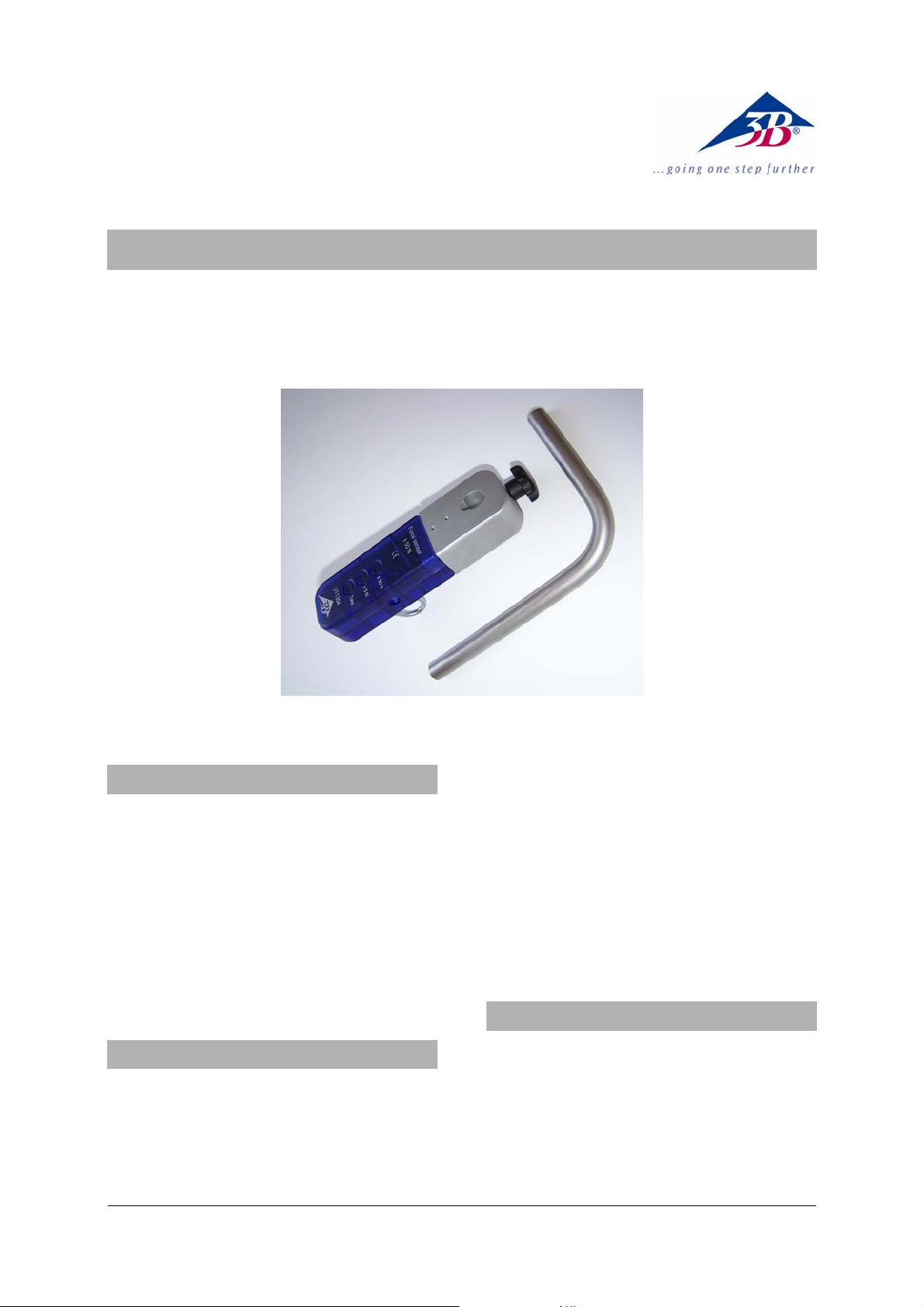
Kraftsensor ± 50 N U11354
Bedienungsanleitung
08/08 Hh
1. Sicherheitshinweise
• Um dauerhafte Beschädigungen der eingebau-
ten Wägezelle zu vermeiden, ein maximale
Krafteinwirkung von ± 150 N nicht überschreiten!
• Das Sensorelement aus keiner größeren Höhe
als maximal 1 m auf einen harten Untergrund
fallen lassen!
• Den Kraftsensor ± 50 N nur für Ausbildungs-
zwecke einsetzen!
Der Kraftsensor ± 50 N ist nicht für Sicherheitsrelevate Anwendungen geeignet!
2. Beschreibung
Sensorbox mit eingebauter Wägezelle und einem
Kraftaufnehmer nach dem Dehnungsmessstreifen
(DMS)-Verfahren.
Auswahl der beiden Messbereiche ± 5 N und ± 50
N mittels Drucktasten.
Signalisierung des gewählten Messbereichs durch
eine Leuchtdiode neben der Taste.
Zusätzliche Tara-Funktion (Kompensation) in beiden Messbereichen.
Beigefügte gewinkelte Stativstange ermöglicht
rechtwinklig versetzte Sensorboxmontagen.
Beigefügter Schraubhaken mit M4-Gewinde gegen
andere M4-Verschraubungen austaschbar.
Die Sensorbox besitzt eine automatische Erkennung
durch das 3B NETlog
1 Kraftsensor ± 50 N
1 Winkel-Stativstange 90 °,
l
= 150 mm, l2 = 95 mm, d = 12 mm
1
1 Schraubhaken M4, d
1 miniDIN-Anschlusskabel 8-pin, 60 cm lang
1 Bedienungsanleitung
TM
.
3. Lieferumfang
= 20 mm
Öse
1
Page 2

4. Technische Daten
7. Versuchsbeispiel
Messbereiche: 0 ... ±5 N,
0 ... ± 50 N
Sensortyp: Wägezelle mit Deh-
nungsmessstreifen (DMS)
Nichtlinearität: typ. ± 0,04 % vom ge-
samten Messbereich
Auflösung: 0,01 N im 5 N-Bereich,
0,1 N im 50 N-Bereich
Kompensation (Tara): max. ± 50 N
Max. Frequenz: typ. 20 Hz
Max. verwendbarer
Stativstangendurchmesser: 13 mm
5. Bedienung
• Die Sensorbox in der Nähe des Experiments
platzieren und den erwarteten Kräften entsprechend befestigen; hierzu gfs. die beigefügte Winkel-Stativstange verwenden.
• Gfs. den Schraubhaken einschrauben - oder
ausschrauben und durch eine andere Kraftaufnahme ersetzen.
• Die Sensorbox mit dem beigefügten miniDIN-
Kabel in einem der beiden analogen Eingänge
(A oder B) des 3B NETlog
• Sensorerkennung („Probe Detect“) abwarten.
• Messbereich auswählen.
• Gfs. für eine Kompensation die Tara-Taste
TM
einstecken.
betätigen.
Die Kompensation ist von der Gebrauchslage des
Kraftsensors abhängig und muss für jeden veränderten Aufbau erneut durchgeführt werden!
• Die Kraftmessung durchführen und im Display
des 3B NETlog
TM
den Messwert der Kraft able-
sen.
6. Anwendungen
Messung einfacher harmonischer Schwingungen
Beobachtung von Reibungskräften
Untersuchungen des Hook’schen Gesetzes
Erfassung der Kräfte auf einem Wagen der Rollen-
fahrbahn
Untersuchung der Kräfte in Flaschenzügen
Messung der Beschleunigung in einem gedämpftschwingenden Feder-Masse-System
Benötigte Geräte:
1 3B NETlog
1 3B NETlab
TM
U11300
TM
U11310
1 Kraftsensor ± 50 N U11354
1 Stativfuß U13270
1 Stativstange, 750 mm lang U15003
1 Schraubenfeder 5 N/m U8401010
1 Wägestück 100 g, aus U30016
• Versuchsaufbau gemäß Fig. 1.
• 3B NETlab
TM
-Anwendung (Template) zum Expe-
riment mit dem Kraftsensor ± 50 N öffnen.
• Wägestück in die Schraubenfeder und diese in
den Kraftsensor ± 50 N einhängen. Darauf achten, dass der Schwingungsvorgang im Bewegungsablauf nicht behindert wird.
• Anschlusskabel des Kraftsensor ± 50 N wie in
Fig. 1 gezeigt über den Sensor legen und um
die Stativstange schlingen.
• Wägestück per Hand an der Schraubenfeder
beruhigen.
• Den Messbereich ± 5 N wählen.
• Tara-Taste des Kraftsensor ± 50 N betätigen
und die Null-Anzeige im Display des 3B NET-
TM
log
kontrollieren.
• Wägestück händisch bis zum Niveau des Stativ-
fußes ziehen und loslassen.
• In 3B NETlab
TM
die Messkurvenaufnahme star-
ten (Fig. 2).
• Messkurve auswerten.
2
Page 3
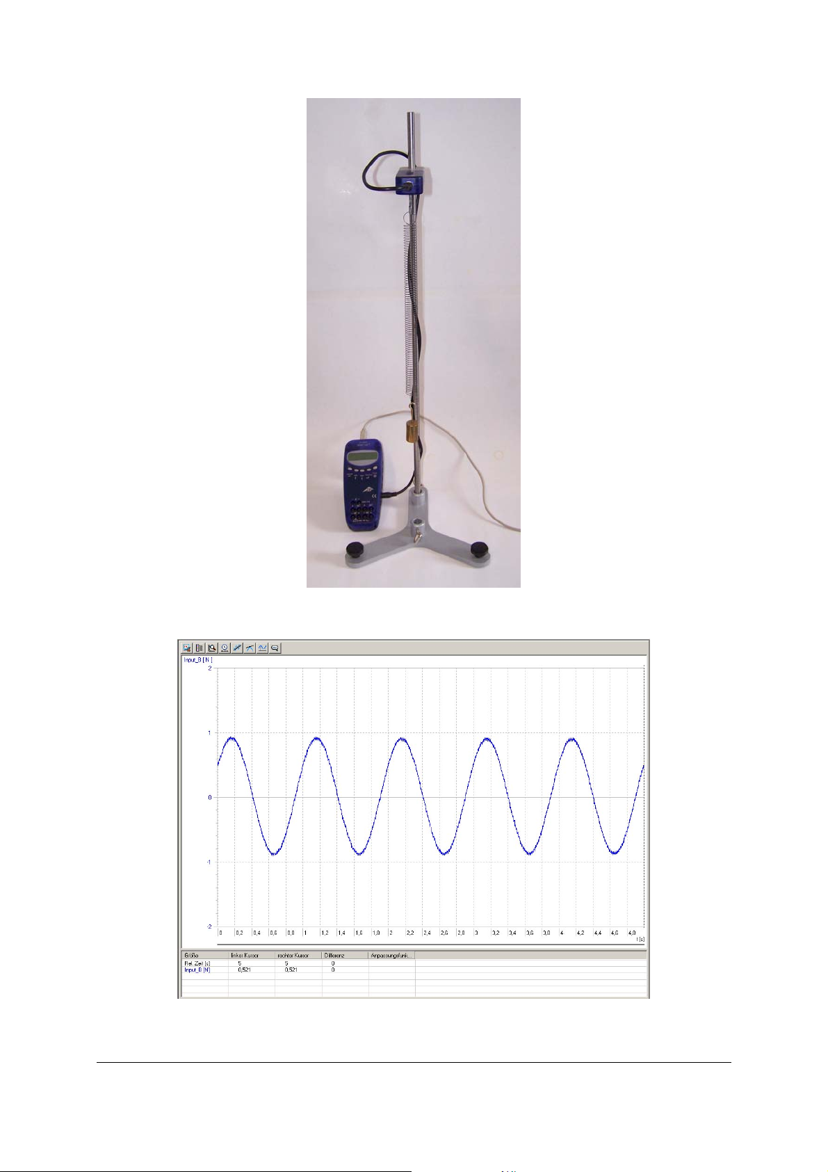
Fig. 1 Messung der Schwingungen in einem schwach gedämpften Feder-Masse-System
Fig. 2 Bildschirmdarstellung einer schwach gedämpften Feder-Masse-Schwingung in 3B NETlabTM (U11310)
3B Scientific GmbH • Rudorffweg 8 • 21031 Hamburg • Deutschland • www.3bscientific.com
Technische Änderungen vorbehalten
© Copyright 2008 3B Scientific GmbH
Page 4

Page 5
3B SCIENTIFIC® PHYSICS
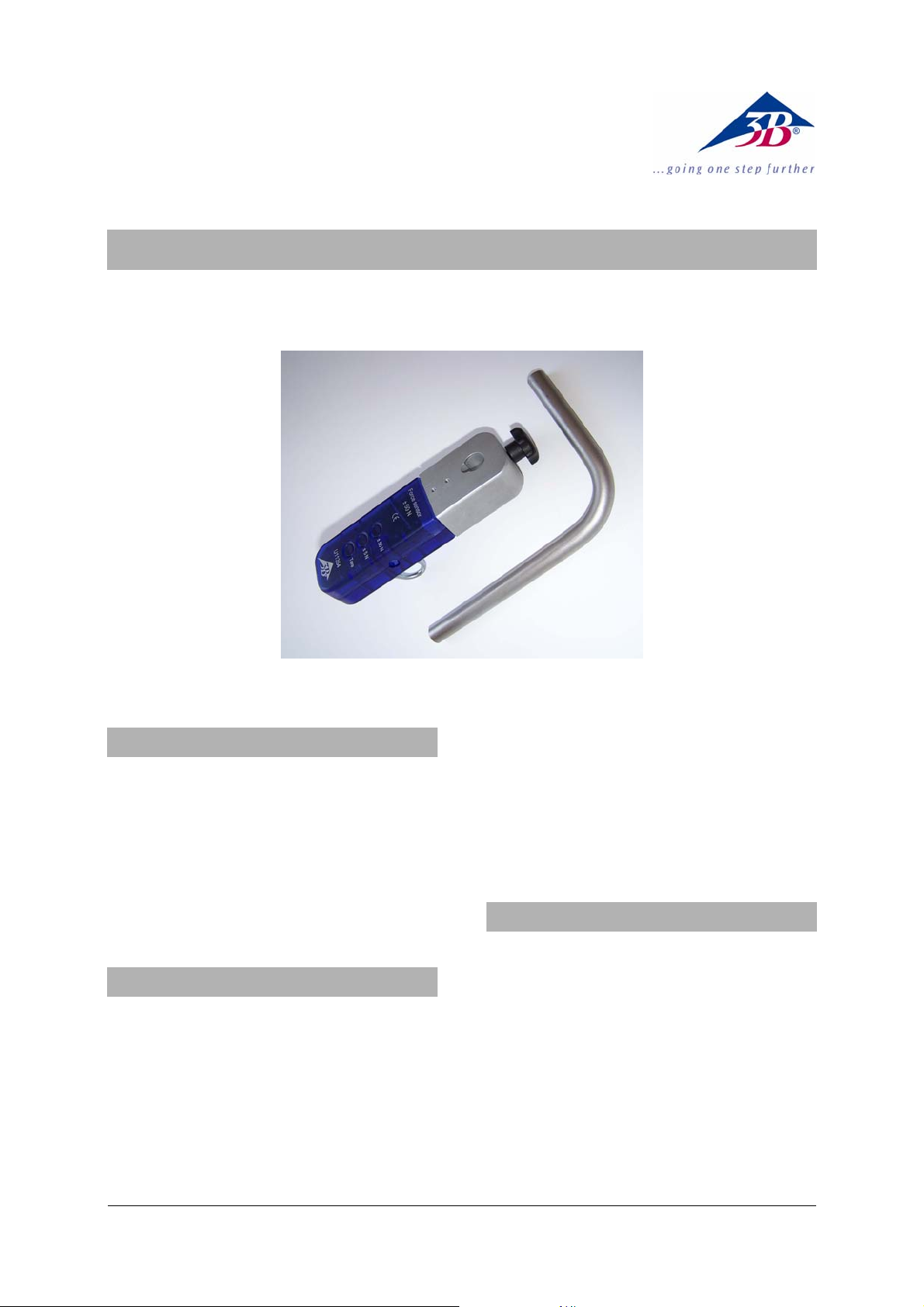
Force Sensor, ± 50 N U11354
Instruction Sheet
08/08 Hh
1. Safety instructions
• To avoid permanent damage to the integrated
load cell, do not exceed the maximum
permitted applied force of ± 150 N!
• Do not allow the sensor unit to fall onto a hard
surface from a height greater than 1 m!
• The ± 150 N force sensor must only be used for
educational purposes!
The ± 150 N force sensor is not suitable for safetyrelated applications!
2. Description
Sensor box incorporating a load cell and a force
sensor working on the foil strain-gauge principle.
Push-buttons allow a choice between two
measurement ranges, ± 5 N and ± 50 N.
The measurement range selected is indicated by an
LED beside the relevant button.
A tare function (compensation of the no-load
reading) is provided for both measurement ranges.
The bent clamping rod that is provided allows the
sensor box to be mounted at 90°.
The screw hook with M4 thread that is provided
can be replaced by any other attachment with an
M4 thread.
The sensor box is designed to be recognised
automatically by the 3B NETlog
3. Equipment supplied
1 Force sensor, ± 50 N
1 Clamping rod with 90° bend,
l
= 150 mm, l2 = 95 mm, d = 12 mm
1
1 Screw hook with M4 thread, eye diameter
20 mm
1 8-pin mini-DIN connecting cable, length 60 cm
1 Instruction sheet
TM
.
1
Page 6

4. Technical data
7. Sample experiments
Measurement ranges: 0 ... ± 5 N,
0 ... ± 50 N
Sensor type: load cell with foil strain-
gauge
Non-linearity: typically ± 0.04% of total
measurement range
Resolution: 0.01 N in 5 N range
0.1 N in 50 N range
Tare compensation: max. ± 50 N
Max. frequency: typically 20 Hz
Max. diameter of
supporting rod: 13 mm
5. Operation
• Place the sensor box near the experiment and
connect it to the point that will apply the
forces; if necessary use the bent clamping rod.
• Screw in the threaded hook if appropriate, or
alternatively replace it by another attachment
for applying force.
• Connect the sensor box to one of the two
analogue inputs (A or B) of the 3B NETlog
TM
using the mini-DIN cable provided.
• Wait for the sensor recognition message
(“Probe Detect”).
• Choose the appropriate measurement range.
• If necessary, press the tare button to apply
compensation.
The tare compensation depends on the position in
which the force sensor is used, and it must be reset
for each new experimental set-up!
• Carry out the force measurement and read the
force value in the display of the 3B NETlog
TM
.
6. Applications
Measurements on simple harmonic oscillations.
Observation of frictional forces.
Investigations of Hooke’s Law.
Measuring the forces on a truck on a track.
Investigation of the forces in pulley systems.
Measuring the acceleration in a damped massand-spring oscillating system
Equipment needed:
1 3B NETlog
1 3B NETlab
TM
U11300
TM
U11310
1 Force sensor, ± 50 N U11354
1 Tripod stand U13270
1 Stainless steel rod, 750 mm U15003
1 Helical spring, 5 N/m U8401010
1 100 g weight, from set of weights U30016
• Set up the experiment as shown in fig. 1.
• On the 3B NETlab
TM
, open the application
(template) for the experiment with the ± 50 N
force sensor.
• Attach the weight to the helical spring and
hang the spring on the force sensor. Ensure
that there is nothing hindering the oscillation
motion.
• Pass the connecting cable of the force sensor
over the sensor and coil it around the stand as
shown in Figure 1.
• Steady the weight by hand so that it is
motionless on the helical spring.
• Select the ± 5 N measurement range.
• Press the tare button of the force sensor and
set the pointer to zero in the display of the
3B NETlog
• Pull the weight down manually to the level of
TM
.
the stand base and release it.
• Start the recording of the force curve on the
3B NETlab
• Interpret and evaluate the curve.
TM
(see fig. 2).
2
Page 7
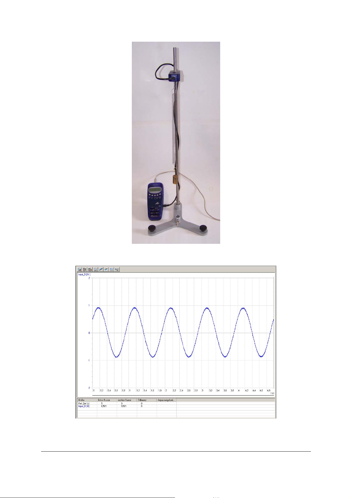
Fig. 1 Measuring the oscillations of a weakly-damped mass-and-spring system
Fig. 2 Oscillations of a weakly-damped mass-and-spring system displayed on the screen of the 3B NETlabTM (U11310)
3B Scientific GmbH • Rudorffweg 8 • 21031 Hamburg • Germany • www.3bscientific.com
Subject to technical amendments.
© Copyright 2007 3B Scientific GmbH
Page 8

Page 9

3B SCIENTIFIC® PHYSICS
Capteur de force ± 50 N U11354
Instructions d'utilisation
08/08 Hh
1. Consignes de sécurité
• Pour éviter un endommagement durable de la
cellule de pesage intégrée, ne dépassez pas
une force de maximale de ± 150 N !
• Ne faites pas tomber la sonde du capteur de
plus de 1 m sur un support dur.
• N'utilisez le capteur de force ± 50 N que pour
les cours de formation.
Le capteur de force ±50 N ne convient pas à des
applications touchant la sécurité !
2. Description
Boîte à capteur à cellule de pesage intégrée et
transducteur de force selon le procédé de jauge
extenso métrique.
Sélection des deux calibres ± 5 N et ± 50 N par
touches de pression.
Signalisation du calibre sélectionné par diode
lumineuse à côté de la touche.
Fonction Tara supplémentaire (compensation) dans
les deux calibres.
La tige statif coudée fournie permet de monter la
boîte décalée en angle droit.
Crochet à vis fourni avec filet M4 remplaçable par
d'autres vissages M4.
La boîte à capteur possède une détection
automatique par le 3B NETlog
3. Matériel fourni
1 capteur de force ±50 N
1 tige statif coudée 90°,
l
= 150 mm, l2 = 95 mm, d = 12 mm
1
1 crochet à vis M4, d
1 câble de connexion mini-DIN à 8 broches, 60 cm
de long
1 instructions d'utilisation
œillet
TM
.
= 20 mm
1
Page 10

4. Caractéristiques techniques
7. Exemple d'expérience
Calibres : 0 ... ±5 N,
0 ... ± 50 N
Type de capteur : cellule de pesage avec
jauge extenso métrique
Non linéarité : typ. ±0,04 % du calibre
Résolution : 0,01 N calibre 5 N,
0,1 N calibre 50 N
Compensation (Tara) : max. ± 50 N
Fréquence max. : typ. 20 Hz
Diamètre max.
utilisable de la
barre de support : 13 mm
5. Manipulation
• Placez la boîte à capteur à proximité de
l'expérience et fixez les forces prévues ; au
besoin, utilisez la tige statif coudée fournie.
• Au besoin, vissez ou dévissez le crochet à vis et
remplacez-le par un autre captage de force.
• Enfichez la boîte à capteur avec le câble
miniDIN fourni dans l'une des deux entrées
analogiques (A ou B) de 3B NETlog
• Attendez la détection du capteur « Probe
TM
.
Detect ».
• Sélectionnez le calibre.
• Au besoin, actionnez la touche Tara pour une
compensation.
La compensation dépend de la position
d'utilisation du capteur de force et doit être
effectuée à chaque modification du montage !
• Mesurez la force et lisez la valeur de la force
dans l'affichage de 3B NETlog
TM
.
6. Applications
Mesure d'oscillations harmoniques simples
Observation de forces de frottement
Études sur la loi de Hooke
Saisie des forces sur un chariot du parcours
roulant.
Étude des forces dans des poulies
Mesure de l'accélération dans un système
amorti-oscillant de ressorts et de poids
Matériel requis :
1 3B NETlog
TM
U11300
1 3B NETlabTM U11310
1 capteur de force ±50 N U11354
1 pied de support U13270
1 tige statif, 750 mm U15003
1 ressort cylindrique 5 N/m U8401010
1 poids de pesage, 100 g, de U30016
• Montez l'expérience comme le montre la figure
1.
• Ouvrez l'application 3B NETlab
TM
(Template)
pour réaliser l'expérience avec le capteur de
force ± 50 N.
• Accrochez le poids de pesage dans le ressort
cylindrique et celui-ci dans le capteur de force
±50 N. Veillez à ce que l'oscillation ne soit pas
gênée dans le déroulement des mouvements.
• Placez le câble de connexion du capteur de
force ±50 N sur le capteur comme le montre la
figure 1 et enveloppez-le autour de la tige
statif.
• Stabilisez le poids de la main sur le ressort
cylindrique.
• Sélectionnez le calibre ± 5 N.
• Actionnez la touche Tara du capteur de force
±50 N et contrôlez l'affichage zéro dans l'écran
de 3B NETlog
• Tirez le poids jusqu'au niveau du pied de
TM
.
support, puis relâchez-le.
• Dans 3B NETlab
TM
, lancez l'enregistrement de la
courbe de mesure (fig. 2).
• Évaluez la courbe de mesure.
2
Page 11

Fig. 1 Mesure des oscillations dans un système faiblement amorti de ressorts et de poids
Fig. 2 Représentation à l'écran d'une oscillation faiblement amortie de ressorts et de poids sous 3B NETlabTM (U11310)
3B Scientific GmbH • Rudorffweg 8 • 21031 Hamburg • Allemagne • www.3bscientific.com
Sous réserve de modifications techniques
© Copyright 20087 3B Scientific GmbH
Page 12

Page 13

3B SCIENTIFIC® PHYSICS
Sensore di forza ± 50 N U11354
Istruzioni per l'uso
08/08 Hh
1. Norme di sicurezza
• Al fine di evitare danni permanenti alla cella
di carico incorporata, non applicare una forza
massima superiore a ± 150 N!
• Non lasciare cadere il sensore su una base
dura da un’altezza maggiore di 1 m max!
• Utilizzare il sensore di forza da ± 50 N solo per
scopi didattici!
Il sensore di forza ± 50 N non è adatto ad
applicazioni importanti per la sicurezza!
2. Descrizione
Scatola del sensore con cella di carico incorporata e
un dinamometro funzionante secondo la
procedura degli estensimetri (DSM)
Selezione dei due range di misura ± 5 N und ± 50
N mediante i pulsanti
Segnalazione del range di misura selezionato
mediante un diodo luminoso accanto al tasto.
Funzione di tara (compensazione) supplementare
in entrambi i range di misura.
L'asta di supporto angolata fornita in dotazione
consente montaggi della scatola del sensore ad
angolo retto.
Ganci a vite con filettatura M4 forniti in dotazione
sostituibili con altri attacchi a vite M4.
La scatola del sensore viene riconosciuta
automaticamente da 3B NETlog
3. Fornitura
1 Sensore di forza ± 50 N
1 Asta di supporto angolata a 90°,
l
= 150 mm, l2 = 95 mm, d = 12 mm
1
1 Gancio a vite M4, d
1 cavo di collegamento miniDIN a 8 pin, lungo 60
cm
1 Istruzioni per l'uso
Occhiello
TM
.
= 20 mm
1
Page 14

4. Dati tecnici
7. Esperimento di esempio
Range di misura: 0 ... ±5 N,
0 ... ± 50 N
Tipo sensore: Cella di carico con
estensimetri (DMS)
Non linearità: solitamente ± 0,04 % del
range di misura totale
Risoluzione: 0,01 N nel range di 5 N,
0,1 N nel range di 50 N,
Compensazione (tara) max. ± 50 N
Frequenza max.: solitamente. 20 Hz
Max. diametro
dell'asta di supporto
utilizzabile: 13 mm
5. Utilizzo
• Collocare la scatola del sensore in prossimità
dell'esperimento e fissare adeguatamente le
forze previste, evt. utilizzando a questo scopo
l'asta di supporto angolata fornita in
dotazione.
• Avvitare evt. i ganci a vite - o svitarli e
sostituirli con un altro alloggiamento per le
forze.
• Inserire la scatola del sensore con i cavi
miniDIN forniti in dotazione in uno die due
ingressi analogici (A o B) di 3B NETlog
• Attendere il rilevamento del sensore (“Probe
TM
Detect”).
• Selezionare il range di misura
• Se necessario azionare il tasto Tara per una
compensazione.
La compensazione dipende dalla posizione di
utilizzo del sensore della forza e deve essere
eseguita ex-novo per ogni cambiamento della
disposizione di montaggio!.
• Eseguire la misuzione della forza e leggere sul
display 3B NETlog
TM
il valore di misura della
forza.
6. Applicazioni
Misurazioni di oscillazioni armoniche semplici
Osservazione di forze di attrito
Analisi della legge di Hook
Rilevamento delle forze su un carrello della rotaia
delle pulegge
Analisi delle forze nei paranchi
Misurazione dell'accelerazione in un sistema
massa - molla oscillante smorzato
Apparecchi necessari:
1 3B NETlog
TM
U11300
1 3B NETlabTM U11310
1 Sensore di forza ± 50 N U11354
1 Base di supporto U13270
1 Asta di supporto, lungh. 750 mm U15003
1 Molla elicoidale 5 N/m U8401010
1 peso da 100 g U30016
• Struttura di prova come da Fig. 1.
• Aprire l'applicazione 3B NETlab
TM
(Template)
per l'esperimento con il sensore di forza ± 50
N.
• Appendere il peso alla molla elicoidale e
questa al sensore di forza ± 50 N Far sì che il
processo di oscillazione non venga ostacolato
durante il movimento.
• Collocare il cavo di collegamento del sensore di
forza ± 50 N sopra il sensore come mostrato
nella figura 1 e avvolgerlo attorno all'asta di
supporto.
• Fermare a mano i pesi sulla molla elicoidale
• Selezionare il range di misura ± 5 N
• Azionare il tasto Tara del sensore di forza ± 50
N e verificare che nel display di 3B NETlog
TM
sia
indicato zero
• Tirare manualmente i pesi fino al livello della
base di supporto e rilasciarli
• Avviare la registrazione della curva di
misurazione in 3B NETlab
• Valutare la curva di misurazione.
TM
(Fig. 2).
2
Page 15

Fig. 1 Misurazione delle oscillazioni in un sistema massa - molla debolmente smorzato
Fig. 2 Rappresentazione della schermata di un'oscillazione massa - molla debolmente smorzata in 3B NETlabTM (U11310)
3B Scientific GmbH • Rudorffweg 8 • 21031 Amburgo • Germania • www.3bscientific.com
Con riserva di modifiche tecniche
© Copyright 2008 3B Scientific GmbH
Page 16

3B SCIENTIFIC® PHYSICS
Sensor de fuerza ± 50 N U11354
Instrucciones de uso
08/08 Hh
1. Advertencias de seguridad
• ¡Para evitar daños permanentes de la célula de
pesado incorporada, no sobrepasar un
impacto de fuerza máximo de ± 150 N!
• ¡No se debe dejar caer el elemento de sensor
sobre una superficie dura desde una altura
mayor que 1 m!
• ¡Utilizar el sensor de fuerzaa ± 50 N sólo para
objetivos didácticos!
¡El sensor de fuerza ± 50 N no es apropiado para
aplicaciones relevantes para la seguridad!
2. Descripción
Caja de sensor con célula de pesado y un captor de
fuerza según el procedimiento de bandas
extensiométricas (DMS).
Selección de los dos posibles alcances de medida ±
5 N y ± 50 N por medio de teclas.
Indicación del alcance de medida seleccionado por
medio de diodo luminoso al lado de la tecla.
Función de tara adicional (compensación) en
ambos alcances de medida.
La varilla soporte acodada que acompaña el
equipo hace posible el desplazamiento en ángulo
recto de montajes de la caja de sensor.
El gancho atornillable con rosca M4 que acompaña
al equipo se puede cambiar por otra unión roscada
M4.
La caja de sensor tiene un reconocimiento
automático por el 3B NETlog
3. Volumen de entrega
1 Sensor de fuerza ± 50 N
1 Varilla soporte acodada 90°,
l
= 150 mm, l2 = 95 mm, d = 12 mm
1
1 Gancho atornillable, d
1 Cable de conexión miniDIN 8-pines, 60 cm de
largo
1 Instrucciones de uso
TM
.
= 20 mm
Öse
1
Page 17

4. Datos técnicos
7. Experimento ejemplar
Alcances de medida: 0 ... ±5 N,
0 ... ± 50 N
Tipo de sensor: Célula de pesado con
bandas extensiométricas
(DMS)
No linealidad: típico ± 0,04 % del
alcance de medida total
Resolución: En alcance 0,01 N 5 N,
En alcance 0,1 N 50 N
Compensación (Tara): max. ± 50 N
Frecuencia max: típica. 20 Hz
Max. diámetro de
varillas soporte
aplicables: 13 mm
5. Manejo
• Se coloca la caja de sensor cerca del
experimento y se fija correspondiendo a las
fuerzas a esperar, para ello, si es necesario se
utiliza la varilla soporte acodada que
acompaña al equipo.
• Si es necesario se atornilla o desatornilla el
gancho de tornillo y se cambia por otro captor
de fuerza.
• La caja de sensor se enchufa en una de las dos
entradas analógicas (A resp. B) del 3B NETlog
TM
,
utilizando el cable miniDIN que acompaña al
equipo.
• Esperar el reconocimiento del sensor („Probe
Detect“).
• Seleccionar el alcance de medida.
• Si es necesario se acciona la tecla-Tara para
realizar una compensación.
¡La compensación depende de la posición de
utilización del sensor de fuerza y se debe realizar
de nuevo para cada variación del montaje de
trabajo!
• Se realiza la medición y se lee el valor de
medida de la fuerza en el display del 3B
TM
NETlog
.
6. Aplicaciones
Medición de oscilaciones armónicas sencillas
Observación de fuerzas de fricción
Estudio de la ley de Hook
Captación de fuerzas sobre un carro en el carril de
ruedas
Estudio de las fuerzas en polipastos y aparejos
Medición de la aceleración en un sistema muelle
– masa de oscilación amortiguada
Aparatos necesarios:
1 3B NETlog
1 3B NETlab
TM
U11300
TM
U11310
1 Sensor de fuerza ± 50 N U11354
1 Pie soporte U13270
1 Varilla soporte, largo 750 mm U15003
1 Muelle helicoidal 5 N/m U8401010
1 Pesa de 100 g, de U30016
• Montaje experimental de acuerdo con la Fig. 1.
• Se abre la aplicación de 3B NETlab
TM
(Templete)
para el experimento con el sensor de fuerza ±
50 N
• La pesa se cuelga del muelle helicoidal y este
último del sensor de fuerza ± 50 N. Tenga en
cuenta de que proceso de oscilación no sea
obstaculizado por al proceso la medición.
• El cable de conexión del sensor de fuerza ± 50
N se enrolla alrededor de la varilla soporte,
como se muestra en la Fig. 1.
• Con la mano se calma la pesa colgada en el
muelle helicoidal.
• Se selecciona el alcance de medida de ± 5 N.
• Se pulsa la tecla del sensor de fuerza ± 50 N y
se controla la indicación ”0”en el display del
3B NETlog
• Con la mano se tira de la pesa hasta el nivel
TM
.
del pie soporte y luego se deja libre.
• Se inicia en el 3B NETlab
TM
el registro de la
curva de medida (Fig. 2).
• Se evalúa la curva de medida.
2
Page 18

Fig. 1 Medición de las oscilaciones levemente amortiguadas de un sistema masa – muelle.
Fig. 2 Representación en la pantalla del 3B NETlabTM (U11310) de una oscilación de masa –muelle levemente amortiguada.
3B Scientific GmbH • Rudorffweg 8 • 21031 Hamburgo • Alemania • www.3bscientific.com
Nos reservamos el derecho a cambios técnicos
© Copyright 2008 3B Scientific GmbH
Page 19

Page 20

3B SCIENTIFIC® FÍSICA
Sensor de força ± 50 N U11354
Instruções de operação
08/08 Hh
1. Indicações de segurança
• Para evitar um dano permanente da célula de
carga instalada, não se deve ultrapassar a ação
de força de ± 150 N!
• Não deixar cair o elemento sensor de uma
altura maior de máximo 1 m sobre una
superfície dura!
• Empregar o sensor de força ± 50 N somente
para fins de instrução!
O sensor de força ± 50 N não é adequado para as
utilizações relativas à segurança!
2. Descrição
Caixa de sensor com célula de carga instalada e um
recipiente de força segundo o processo de
extensômetro (DMS).
Seleção dos dois âmbitos de medição ± 5 N e ± 50
N por meio de teclas de pressão.
Sinalização do âmbito de medição a través de um
díodo luminoso ao lado da tecla.
Função de tara adicional (compensação) em ambos
os âmbitos de medição.
Uma vara de apoio angular incluída permite a
montagem da caixa do sensor deslocada em ângulo
reto.
Um gancho de parafuso com rosca M4 incluído é
intercambiável com outros parafusados M4.
A caixa de sensor tem um reconhecimento
automático a través do 3B NETlog
3. Fornecimento
1 Sensor de força ± 50 N
1 Vara de apoio angular 90 °,
l
= 150 mm, l2 = 95 mm, d = 12 mm
1
1 gancho de parafuso M4, d
1 Cabo de conexão miniDIN- 8-pin, comprimento
de 60 cm
1 Instrução de operação
TM
.
= 20 mm
Öse
1
Page 21

4. Dados técnicos
7. Exemplo de experiência
Âmbitos de medição: 0 ... ± 5 N,
0 ... ± 50 N
Tipo de sensor: Sensor de carga com
extensômetro (DMS)
Não linearidade: típ. ± 0,04 % do âmbito
de medição total
Dissolução: 0,01 N no âmbito 5 N,
0,1 N no âmbito 50 N
Compensação (Tara): máx. ± 50 N
Freqüência máx.: típ. 20 Hz
Diâmetro máx. utilizável
da vara de apoio: 13 mm
5. Operação
• Situar a caixa de sensor na proximidade da
experiência e fixar de acordo as forças
previstas; para isto, eventualmente empregar a
vara de apoio angular incluída..
• No caso enroscar o gancho de parafuso ou
desenroscar e substituí-lo por outro receptivo
de força.
• Conectar a caixa de sensor com o cabo miniDIN
incluído em uma das duas entradas análogas
(A ou B) do 3B NETlog
• Esperar pelo reconhecimento de sensor („Probe
TM
.
Detect“).
• Selecionar o âmbito de medição.
• Eventualmente acionar a tecla-tara para a
compensação.
A compensação é dependente da colocação em uso
do sensor de força e tem que ser feita novamente
para cada montagem diferente!
• Realizar a medição de força e ler no painel de
exibição do 3B NETlog
TM
o valor da força
medido.
6. Aplicação
Medição de vibrações harmônicas simples
Observação de forças de atrito
Exame da lei de Hook
Compreensão das forças sobre um carro da pista de
roldanas
Compreensão das forças em polipasto de roldanas
Medição da aceleração num sistema mola-peso
oscilando baixo.
Aparelhos necessários:
1 3B NETlog
1 3B NETlab
TM
U11300
TM
U11310
1 Sensor de forças ± 50 N U11354
1 Um tripé U13270
1 Vara de apoio, 750 mm comprimento U15003
1 Uma mola helicoidal 5 N/m U8401010
1 Peça de peso 100 g, de U30016
• Montagem da experiência segundo Fig. 1.
• Abrir a aplicação para a experiência com o
sensor de forças ± 50 N (Template) 3B
TM
NETlab
• Pendurar a peça de peso na mola helicoidal e
-.
a esta no sensor de força ± 50 N. Considerar
em isto, que o processo de oscilação não seja
estorvado na evolução do movimento.
• Colocar o cabo de conexão do sensor de força
± 50 N como mostrado na Fig. 1 sobre o sensor
e entrelaçar em volta da vara de apoio.
• Aquietar a peça de peso na mola helicoidal
com a mão.
• Selecionar o âmbito de medição ± 5 N.
• Acionar a tecla-tara do sensor de força ± 50 N
e controlar o indicador Zero no painel de
exibição do 3B NETlog
• Puxar com a mão a peça de peso até o nível do
TM
.
tripé e deixar cair.
• Começar a tomada de curvas de medição no 3B
• Avaliar a curva de medição.
NETlab
TM
(Fig. 2).
2
Page 22

Fig. 1 Medição das oscilações num sistema fraco-baixo de mola-peso
Fig. 2 Representação da tela do 3B NETlabTM (U11310) de uma oscilação de mola-peso fraco-baixas
3B Scientific GmbH • Rudorffweg 8 • 21031 Hamburgo • Alemanha • www.3bscientific.com
Sob reserva de alterações técnicas
© Copyright 2008 3B Scientific GmbH
Page 23

 Loading...