

Page 1
3B SCIENTIFIC
Bedienungsanleitung
07/10 ALF
®
PHYSICS
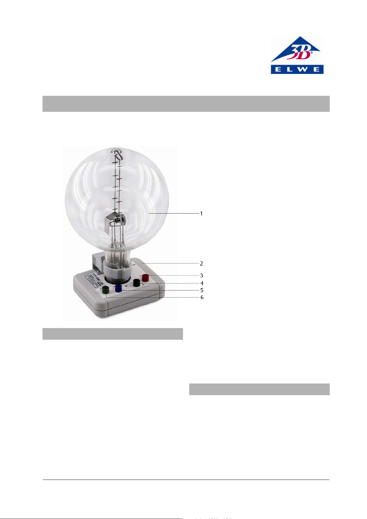
Fadenstrahlröhre U8481430
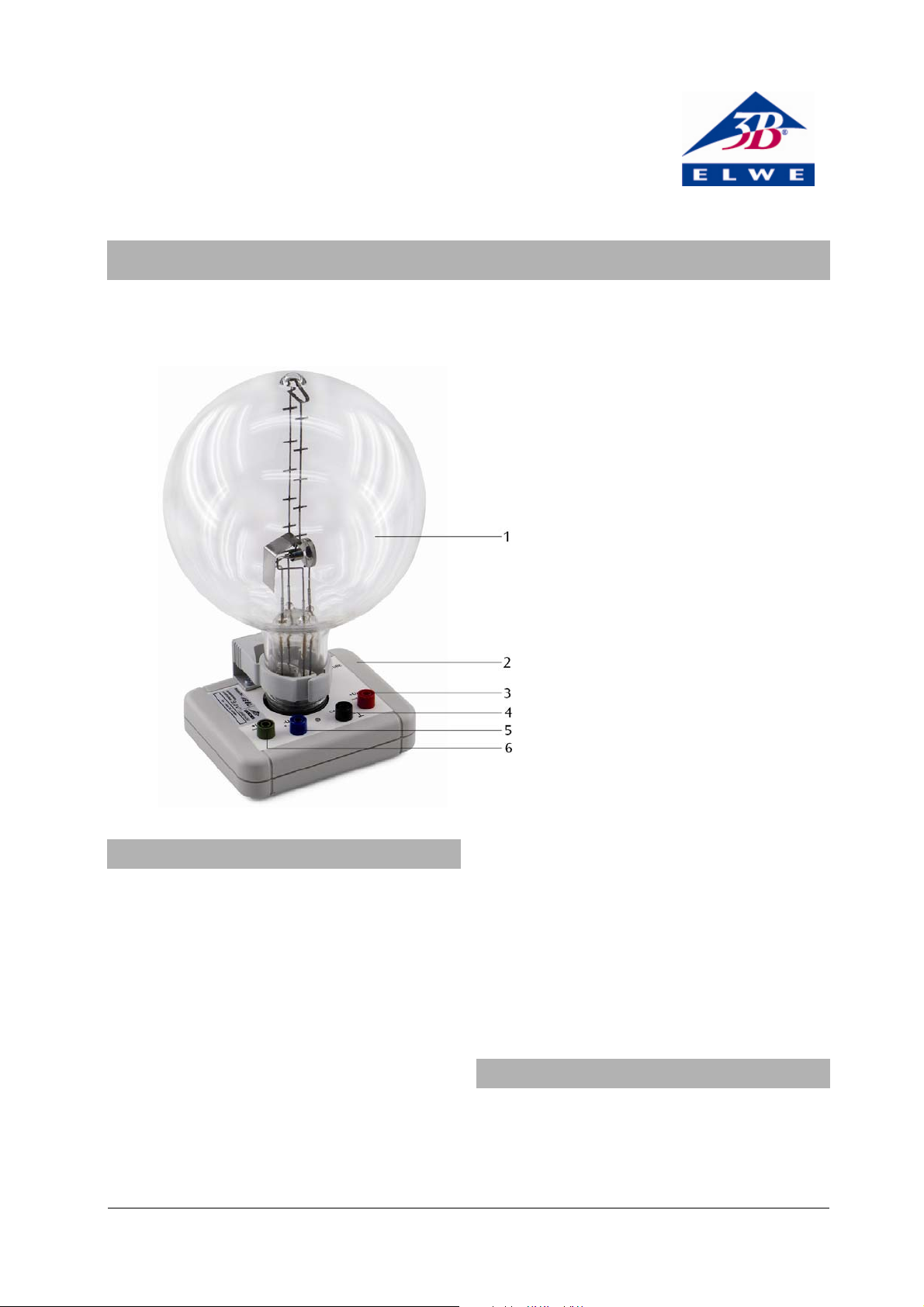
1 Fadenstrahlröhre
2 Anschlusssockel
3 Anschluss für Anode
4 Anschluss für Katode
5 Anschluss für Wehnelt-Zylinder
6 Anschluss für Heizung
1. Sicherheitshinweise
Glühkatodenröhren sind dünnwandige, evakuierte
Glaskolben. Vorsichtig behandeln: Implosionsgefahr!
• Röhre keinen mechanischen Belastungen aus-setzen.
Zu hohe Spannungen, Ströme sowie falsche Katodenheiztemperatur können zur Zerstörung der Röhre
führen.
• Die angegebenen Betriebsparameter einhalten.
Beim Betrieb der Röhre können am Anschlussfeld
berührungsgefährliche Spannungen und Hochspannungen anliegen.
• Für Anschlüsse nur Sicherheits-Experimentier-
kabel verwenden.
• Schaltungen nur bei ausgeschaltetem Versor-
gungsgerät vornehmen.
• Röhre nur bei ausgeschaltetem Versorgungsgerät
ein- und ausbauen.
Im Betrieb erwärmt sich der Röhrenhals.
• Röhre vor dem Wegräumen abkühlen lassen.
Die Einhaltung der EC Richtlinie zur elektromagnetischen Verträglichkeit ist nur mit den empfohlenen
Netzgeräten garantiert.
2. Beschreibung
Die Fadenstrahlröhre dient zur Untersuchung der Ablenkung von Elektrodenstrahlen im homogenen Magnetfeld unter Verwendung des Helmholtzspulenpaars
U8481500 sowie zur quantitativen Bestimmung der
spezifischen Ladung des Elektrons e/m.
In einem Glaskolben befindet sich die Elektronenkanone, bestehend aus einer indirekt geheizten Oxidkatode, einem Wehneltzylinder und einer Lochanode in
einer Neonrestgas-Atmosphäre mit präzise eingestelltem Gasdruck. Die Gasatome werden längs der Elekt-
1
Page 2
ronenflugbahn ionisiert und es entsteht ein leuchten-
r
r
⋅
⋅
=
der, scharf begrenzter Strahl. Eingebaute Messmarken
erlauben die parallaxenfreie Bestimmung des Kreisbahndurchmessers des im Magnetfeld abgelenkten
Strahls.
Die Fadenstrahlröhre ist auf einem Sockel mit farbigen
Anschlussbuchsen montiert. Zum Schutz der Röhre ist
im Sockel eine Schutzschaltung installiert, die die
Spannung oberhalb der auf dem Röhrensockel angegebenen „Cutoff-Voltage“ (Abschaltspannung) abschaltet. Die Schutzschaltung verhindert, dass eine zu hohe
Spannung die Heizung zerstört und sorgt dafür, dass
beim Einschalten die Spannung „weich“ hochfährt.
3. Technische Daten
Gasfüllung: Neon
Gasdruck: 1,3 x 10
-5
bar
Heizspannung: 4 bis 12 V DC (siehe Angabe
„Cutoff-Voltage“ auf dem Röh-
rensockel)
Heizstrom: 300 bis 450 mA
Wehneltspannung: 0 bis -50 V
Anodenspannung: 200 bis 300 V
Anodenstrom: < 0,3 mA
Fadenstrahlkreis: 20 bis 120 mm Ø
Messmarkenabstand: 20 mm
Kolbendurchmesser: 160 mm
Gesamthöhe: 260 mm
Anschlusssockel: 115 x 115 x 35 mm
3
Masse: ca. 820 g
4. Allgemeine Grundlagen
Auf ein Elektron, das sich mit der Geschwindigkeit v
senkrecht zu einem homogenen Magnetfeld B bewegt,
wirkt senkrecht zur Geschwindigkeit und zum Magnetfeld die Lorentz-Kraft
BveF ⋅⋅= (1)
e: Elementarladung
Sie zwingt das Elektron als Zentripetalkraft
2
vm
⋅
F
=
(2)
m: Elektronenmasse
auf eine Kreisbahn mit dem Radius r. Daher ist
vmBe⋅
=⋅
(3)
Die Geschwindigkeit v hängt von der Beschleunigungsspannung U der Elektronenkanone ab:
e
v ⋅⋅= 2 (4)
U
m
Für die spezifische Ladung des Elektrons gilt somit:
2
e
m
U
= (5)
2
()
Br
⋅
Misst man für verschiedene Beschleunigungsspannungen U und verschiedene Magnetfelder B jeweils den
Kreisbahnradius r, so liegen die Messwerte in einem
2B2
r
-2U-Diagramm gemäß Gl. (5) auf einer Ursprungsge-
raden mit der Steigung e/m.
Das Magnetfeld B wird in einem Helmholtz-Spulenpaar
erzeugt und ist proportional zum Strom I
durch eine
H
einzelne Spule. Der Proportionalitätsfaktor k kann aus
dem Spulenradius R = 147,5 mm und der Windungszahl N = 124 je Spule berechnet werden:
3
IkB
H
mit
2
4
⎞
⎛
k =⋅⋅π⋅
=
⎟
⎜
5
⎠
⎝
−
104
N
Vs
7
R
Am
mT
,
7560
A
Damit sind sämtliche Bestimmungsgrößen für die
spezifische Elektronenladung bekannt.
5. Zusätzlich erforderliche Geräte
1 DC-Netzgerät 300 V (230 V, 50/60 Hz) U8521371-230
oder
1 DC-Netzgerät 300 V (115 V, 50/60 Hz) U8521371-115
und
1 DC-Netzgerät 20 V, 5 A (230 V, 50/60 Hz) U33020-230
oder
1 DC-Netzgerät 20 V, 5 A (115 V, 50/60 Hz) U33000-115
oder
1 DC-Netzgerät 500 V (230 V, 50/60 Hz) U33000-230
oder
1 DC-Netzgerät 500 V (115 V, 50/60 Hz) U33000-115
1 Helmholtz-Spulenpaar U8481500
1 bzw. 2 Analog-Multimeter AM50 U17450
Sicherheits-Experimentierkabel
6. Bedienung
6.1 Aufbau
• Fadenstrahlröhre zwischen die Helmholtzspulen
stellen.
• Um den Elektronenstrahl besser beobachten zu
können, das Experiment in einem abgedunkelten
Raum durchgeführen.
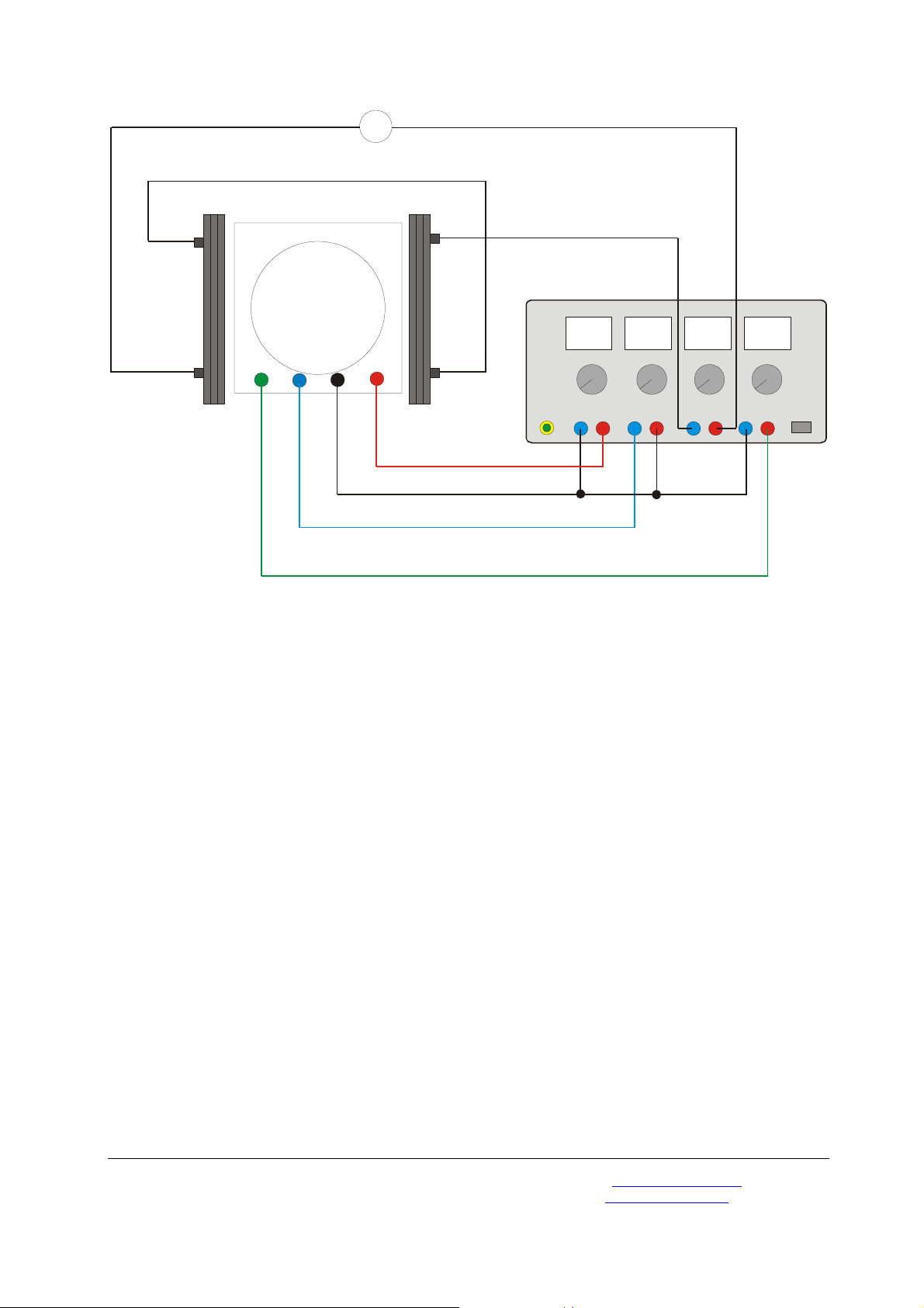
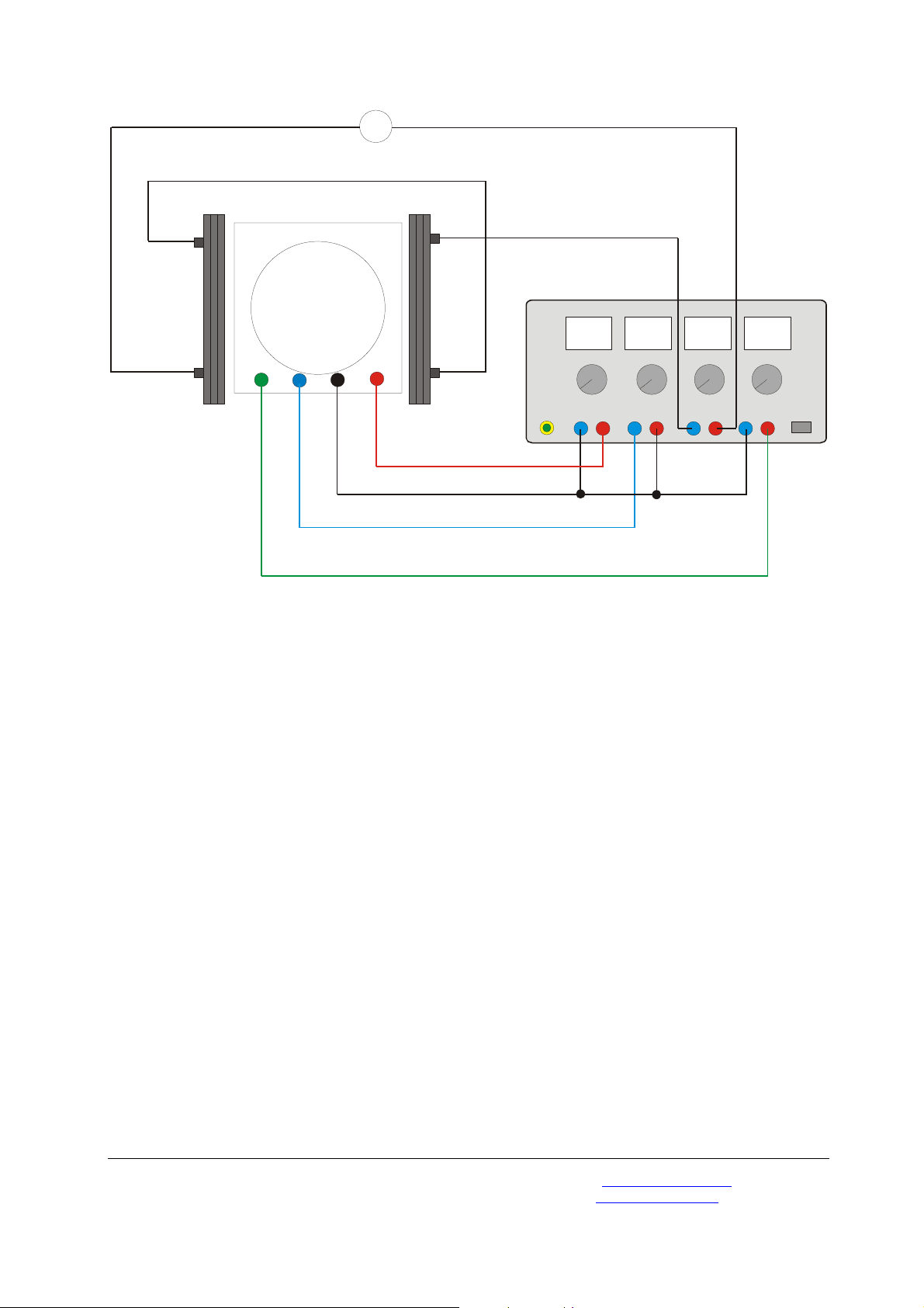
6.1.1 Betrieb mit dem DC-Netzgerät 300 V U8521371
• Beschaltung gemäß Fig. 1 durchführen.
• Volmeter an den 300-V-Ausgang des Netzgerätes
anschließen.
2
Page 3
• Spulen gemäß Fig. 2 in Reihe an das DC-Netzgerät
20 V U33020 anschließen, so dass beide Spulen
gleichsinnig vom Strom durchflossen werden.
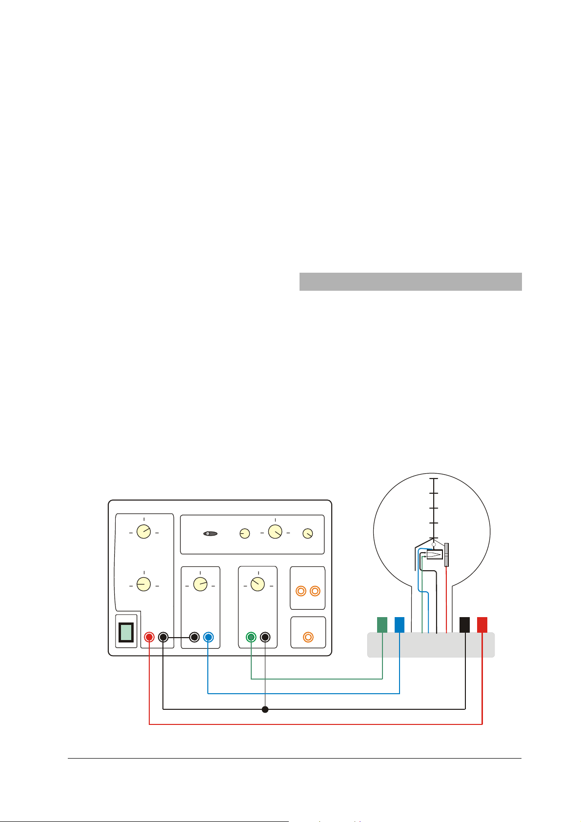
6.1.2 Betrieb mit dem DC-Netzgerät 500 V U33000
• Beschaltung gemäß Fig. 4 durchführen.
6.2 Justierung des Elektronenbündels
• Heizspannung von z.B. 7,5 V anlegen. (Die Heiz-
spannung muss unter der „Cutoff-Voltage“ liegen.)
• Ca. 1 Minute abwarten bis sich die Temperatur der
Heizwendel stabilisiert hat.
• Anodenspannung langsam bis auf max. 300 V
erhöhen (der zunächst waagerechte Elektronenstrahl wird durch ein schwaches, bläuliches Licht
sichtbar).
• Wehnelt-Spannung so wählen, dass ein möglichst
dünnes, scharf begrenztes Strahlenbündel zu sehen ist.
• Schärfe und Helligkeit des Strahlenbündels durch
Variation der Heizspannung optimieren.
• Spulenstrom I
durch die Helmholtz-Spulen erhö-
H
hen und überprüfen, ob der Elektronenstrahl nach
oben gekrümmt wird.
Falls keine Krümmung des Elektronenstrahls zu beobachten ist:
• Eine der Spulen umpolen, so dass der Strom
gleichsinnig durch beide Spulen fließt.
Falls die Krümmung des Elektronenstrahls nicht nach
oben zeigt:
• Zum Umpolen des Magnetfeldes die Anschlusska-
bel am Netzgerät vertauschen.
• Spulenstrom weiter erhöhen und überprüfen, ob
der Elektronenstrahl eine in sich geschlossene
Kreisbahn bildet.
Falls die Kreisbahn nicht geschlossen ist:
• Fadenstrahlrohr samt Sockel etwas um die vertika-
le Achse drehen.
7. Versuchsbeispiel
Bestimmung der spezifischen Ladung des Elektrons
e/m
• Spulenstrom so wählen, dass der Kreisbahnradius
z. B. 5 cm beträgt. Eingestellten Wert notieren.
• Anodenspannung in 20-V-Schritten auf 200 V ver-
kleinern, jeweils den Spulenstrom I
so wählen,
H
dass der Radius konstant bleibt. Diese Werte notieren.
• Weitere Messreihen für die Kreisbahnradien 4 cm
und 3 cm aufnehmen.
• Zur weiteren Auswertung die Messwerte in einem
2B2
r
-2U-Diagramm auftragen (siehe Fig. 3).
Die Steigung der Ursprungsgeraden entspricht e/m.
U8521371
0...300 V 6...12 V0...-50 V
ı
O
Off
On
PE
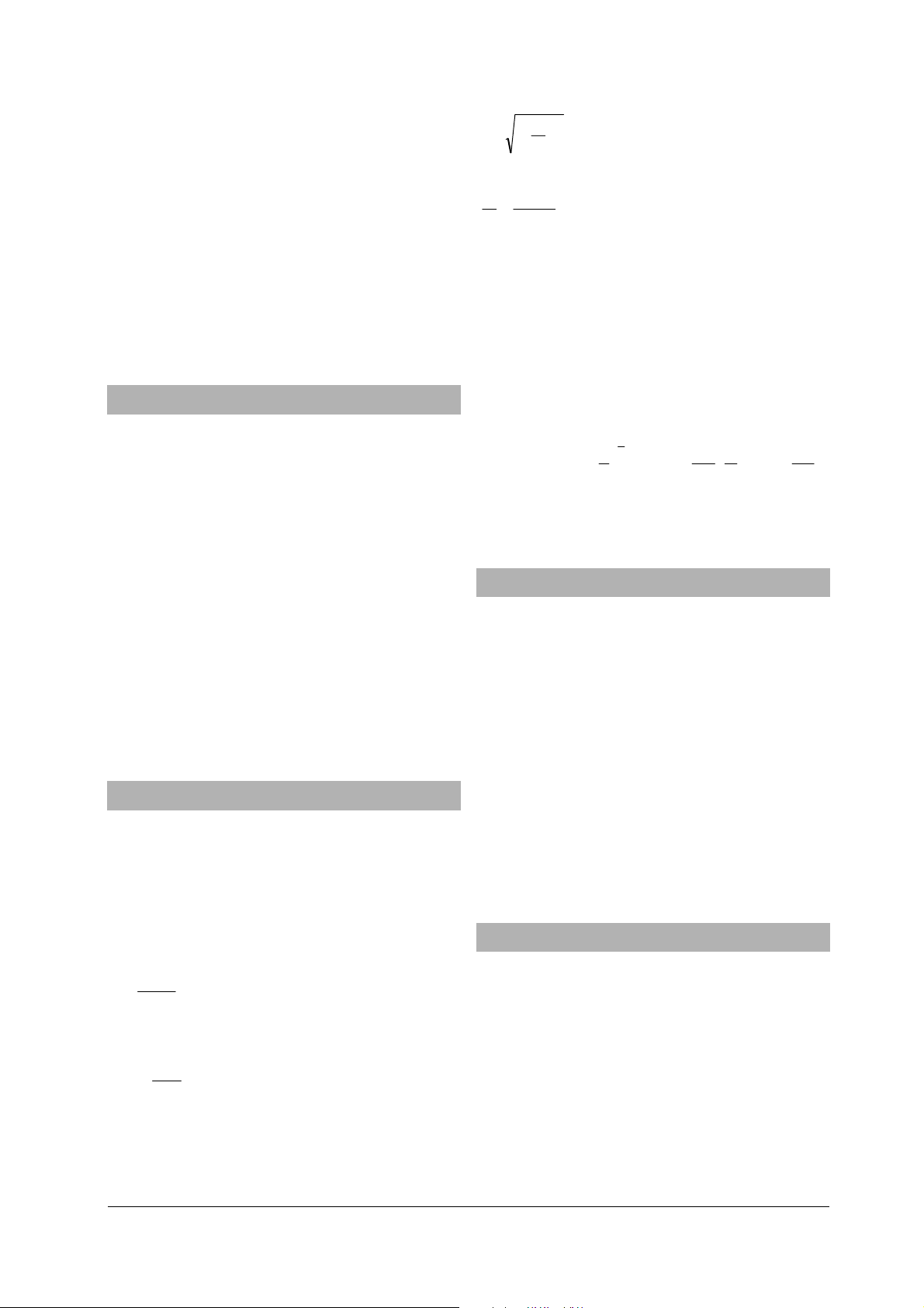
Fig. 1 Anschluss der Fadenstrahlröhre an das DC-Netzgerät 300 V U8521371
3
Page 4
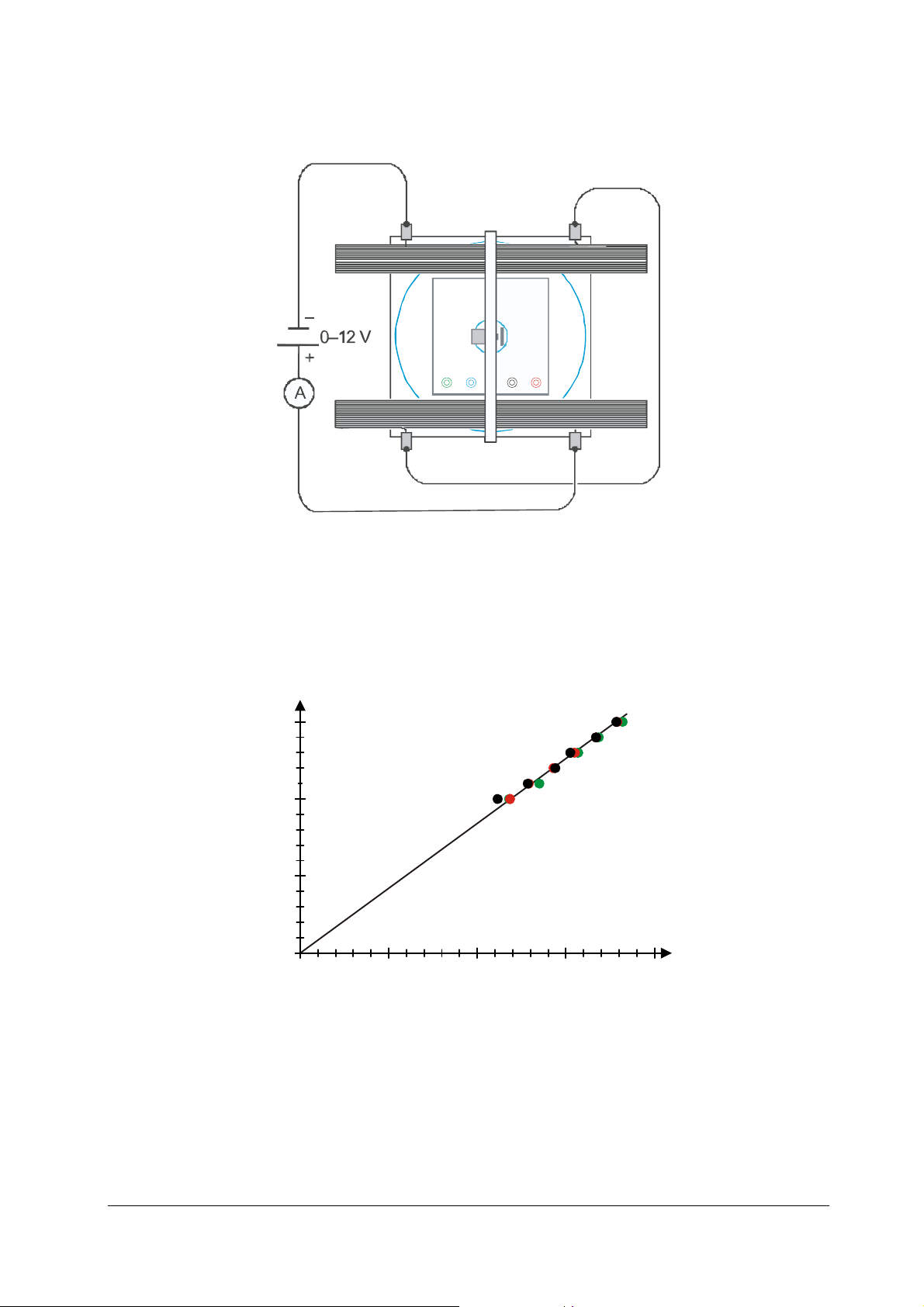
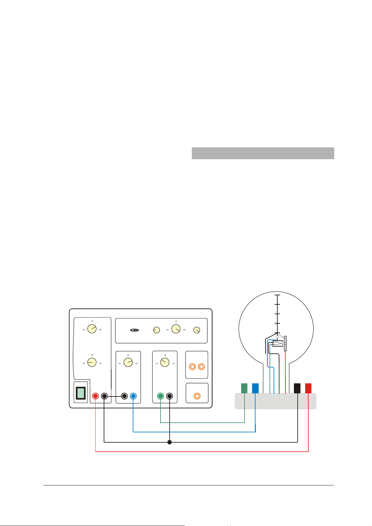
Fig. 2 Beschaltung der Helmholtz-Spulen
2 / V
U
600
400
200
0
100
Fig. 3 r2B2-2U-Diagramm der Messwerte (schwarz: r = 5 cm, rot: r = 4 cm, grün: r = 3 cm)
20 30 40
22 2 2
Br
/ mT cm
4
Page 5
A
U33000
0...500 V 0...50 V 0...8 V 0...12 V
+
-
+
-
Fig. 4 Anschluss der Fadenstrahlröhre an das DC-Netzgerät 500 V U33000
-
+
-
+
Elwe Didactic GmbH • Steinfelsstr. 6 • 08248 Klingenthal • Deutschland • www.elwedidactic.com
3B Scientific GmbH • Rudorffweg 8 • 21031 Hamburg • Deutschland • www.3bscientific.com
Technische Änderungen vorbehalten
© Copyright 2010 3B Scientific GmbH
Page 6

Page 7
3B SCIENTIFIC
Instruction sheet
07/10 ALF
®
PHYSICS
Fine Beam Tube U8481430
1 Fine beam tube
2 Connector base
3 Connection for anode
4 Connection for cathode
5 Connection for Wehnelt cylinder
6 Connection for heater
1. Safety instructions
Hot cathode tubes are thin-walled, highly evacuated
glass tubes. Treat them carefully as there is a risk of
implosion.
• Do not subject the tube to mechanical stresses.
If voltage or current is too high or the cathode is at the
wrong temperature, it can lead to the tube becoming
destroyed.
• Do not exceed the stated operating parameters.
When the tube is in operation, the terminals of the
tube may be at high voltages with which it is dangerous to come into contact.
• Only use safety experiment leads for connecting
circuits.
• Only change circuits with power supply switched
off.
• Set up or dismantle the tubes only when the power
supply unit is switched off.
When the tube is in operation, the stock of the tube
may get hot.
• Allow the tube to cool before putting away the
apparatus.
The compliance with the EC directive on electromagnetic compatibility is only guaranteed when using the
recommended power supplies.
2. Description
The Fine Beam Tube is used for investigating the deflection of cathode rays in a uniform magnetic field
produced by a pair of Helmholtz coils (U8481500). In
addition, it can also be used for quantitative determination of the specific charge of an electron e/m.
1
Page 8

Located inside a glass bulb with a neon residual gas atmos-
r
⋅
⋅
=
phere is an electron gun, which consists of an indirectly
heated oxide cathode, a Wehnelt cylinder and a perforated
anode. The gas atoms are ionised along the path of the
electrons and a narrow, well-defined, luminescent beam is
produced. Incorporated measurement marks facilitate a
parallax-free determination of the diameter of the circular
path of the beam deflected in the magnetic field.
The Fine Beam Tube is mounted on a base with coloured connectors. In order to protect the tube, a protective circuit is built into the base, which shuts off any
voltage in excess of the base’s pre-set cut-off voltage.
The protective circuit prevents excessive voltages from
damaging the heater filament and ensures a “smooth”
switch-on response once the voltage is applied.
3. Technical data
Gas filling: Neon
Gas pressure: 1,3 x 10
-5
bar
Filament voltage: 4 to 12 V DC (see cut-off-
voltage on tube socket)
Filament current: 300 to 450 mA
Wehnelt voltage: 0 bis -50 V
Anode voltage: 200 to 300 V
Anode current: < 0.3 mA
Diameter of fine beam path: 20 to 120 mm
Division spacing: 20 mm
Tube diameter: 160 mm
Total height incl. base: 260 mm
Base plate: 115 x 115 x 35 mm
3
Weight: approx. 820 g
4. Basic principles
An electron moving with velocity v in a direction per-
pendicular to a uniform magnetic field B experiences a
Lorentz force in a direction perpendicular to both the
velocity and the magnetic field
BveF ⋅⋅= (1)
e: elementary charge
This gives rise to a centripetal force on the electron in
a circular path with radius r, where
2
vm
⋅
F
=
and (2)
m is the mass of an electron.
Thus,
vmBe⋅
(3)
=⋅
r
The velocity v depends on the accelerating voltage of
the electron gun:
e
v ⋅⋅= 2 (4)
U
m
Therefore, the specific charge of an electron is given
by:
e
m
U
2
= (5)
2
()
Br
⋅
If we measure the radius of the circular orbit in each
case for different accelerating voltages U and different
magnetic fields B, then, according to equation 5, the
measured values can be plotted in a graph of r
2B2
against 2U as a straight line through the origin with
slope e/m.
The magnetic field B generated in a pair of Helmholtz
coils is proportional to the current I
passing through a
H
single coil. The constant of proportionality k can be
determined from the coil radius R = 147.5 mm and the
number of turns N = 124 per coil:
IkB
where
H
3
2
4
⎞
⎛
k =⋅⋅π⋅
=
⎟
⎜
5
⎠
⎝
Vs
N
7
−
104
Am
R
mT
,
7560
A
Thus, all parameters for the specific charge are known.
5. Additionally required equipment
1 DC power supply 300 V (230 V, 50/60 Hz) U8521371-230
or
1 DC power supply 300 V (115 V, 50/60 Hz) U8521371-115
and
1 DC power supply 20 V, 5 A (230 V, 50/60 Hz) U33020-230
or
1 DC power supply 20 V, 5 A (115 V, 50/60 Hz) U33000-115
or
1 DC power supply 500 V (230 V, 50/60 Hz) U33000-230
or
1 DC power supply 500 V (115 V, 50/60 Hz) U33000-115
1 Pair of Helmholtz coils U8481500
1 resp. 2 Analogue multimeter AM50 U17450
Safety leads
6. Operation
6.1 Set up
• Place the fine beam tube between the Helmholtz
coils.
• To get a clearer view of the electron beam, con-
duct the experiment in a darkened room.
6.1.1 Set up with the DC power supply unit 300 V
U8521371
• Set up the tube as in fig. 1.
2
Page 9
• Connect the voltmeter in parallel to the 300-V
output.
• Connect the coils in series to the DC power supply
20 V U33020, as shown in Fig. 2, so that equal current passes through both coils.
6.1.2 Set up with the DC power supply unit 500 V
U33000
• Set up the tube as in fig. 4.
6.2 Adjusting the electron beam
• Apply a heater voltage of say 7.5 V. (the heater
voltage must be below the cut-off voltage).
• Wait about 1 minute for the heater temperature to
stabilise.
• Slowly increase the anode voltage to 300 V (the
electron beam is initially horizontal and is visible
as a weak, bluish ray).
• Select the Wehnelt voltage so that a very clear and
narrow electron beam is visible.
• Optimise the focus and brightness of the electron
beam by varying the heater voltage.
• Increase the current I
passing through the Helm-
H
holtz coils and check that the electron beam
curves upwards.
• If the electron beam is not deflected at all:
• Reverse the polarity of one of the coils so that
current passes in the same direction through both
coils.
If the electron beam does not curve upwards:
• Swap the connections on the power supply unit to
reverse the polarity of the magnetic field.
• Continue increasing the current passing through
the coils watch until the electron beam forms a
closed circle.
If the path does not form a closed circle:
• Slightly turn the fine beam tube, along with its
base, around its vertical axis.
7. Sample experiment
Determination of the specific charge of an electron
e/m
• Select the current passing through the coils so that
the radius of the circular path is for example 5 cm.
Note the set current value.
• Decrease the anode voltage in steps of 20 V to
200 V. In each case, set the coil current I
so that the
H
radius remains constant. Take down these values.
• Record other series of measured values for radii of
4 cm and 3 cm.
U8521371
0...300 V 6...12 V0...-50 V
ı
O
Off
On
• For further evaluation, plot the measured values in
a graph of r
2B2
against 2U (see Fig. 3).
The slope of the line through the origin corresponds to e/m.
PE
Fig. 1 Electrical connections from the fine beam tube to the DC power supply unit 300 V U8521371
3
Page 10

Fig. 2 Electrical connections to the pair of Helmholtz coils
2 / V
U
600
400
200
0
100
Fig. 3 Graph of r2B2 against 2U for values as measured (black: r = 5 cm, red: r = 4 cm, green: r = 3 cm)
20 30 40
22 2 2
Br
/ mT cm
4
Page 11
A
U33000
0...500 V 0...50 V 0...8 V 0...12 V
+
-
-
Fig. 4 Electrical connections from the fine beam tube to the DC power supply 500 V U33000
+
-
+
-
+
Elwe Didactic GmbH • Steinfelsstr. 6 • 08248 Klingenthal • Germany • www.elwedidactic.com
3B Scientific GmbH • Rudorffweg 8 • 21031 Hamburg • Germany • www.3bscientific.com
Subject to technical amendments
© Copyright 2010 3B Scientific GmbH
Page 12

Page 13

3B SCIENTIFIC
Tube à pinceau étroit U8481430
Instructions d’utilisation
07/10 ALF
®
PHYSICS
1 Tube à pinceau étroit
2 Socle de connexion
3 Connexion pour l’anode
4 Connexion pour la cathode
5 Connexion pour le cylindre de Wehnelt
6 Connexion pour le chauffage
1. Consignes de sécurité
Les tubes thermoioniques sont des cônes en verre à
paroi mince sous vide. Manipulez-les avec précaution :
risque d'implosion !
• N'exposez pas le tube à des charges mécaniques.
Des tensions et des courants trop élevés ainsi que des
températures de chauffage de la cathode mal réglées
peuvent entraîner la destruction du tube.
• Respectez les paramètres de service indiqués.
Des tensions et hautes tensions dangereuses peuvent
apparaître à hauteur du champ de connexion pendant
l'utilisation des tubes.
• Pour les connexions, utilisez uniquement des câ-
bles d'expérimentation de sécurité.
• Ne procédez à des câblages que lorsque les dispo-
sitifs d'alimentation sont éteints.
• Ne montez et ne démontez le tube qu'après avoir
mis l'appareil d'alimentation hors tension.
Pendant l'utilisation du tube, son col chauffe.
• Laisser refroidir le tube avant de le ranger.
Le respect de la directive CE sur la compatibilité électromagnétique est uniquement garanti avec les alimentations recommandées.
2. Description
Le tube à pinceau étroit sert à l'étude de la déviation
de faisceaux électroniques dans un champ magnétique
homogène à l'aide de la paire de bobines Helmholtz
U8481500 ainsi qu'à la détermination quantitative de
la charge spécifique e/m de l'électron.
Un piston en verre renferme les canons électroniques
1
Page 14

constitués d'une cathode d'oxyde à chauffage indirect,
r
r
⋅
⋅
=
d'un cylindre de Wehnelt et d'une anode trouée, en
atmosphère de gaz résiduel au néon avec une pression
gazeuse précise. Les atomes gazeux sont ionisés sur toute
la trajectoire des électrons, formant un faisceau brillant à
coupure nette. Des repères de mesure permettent de
déterminer le diamètre du chemin circulaire du rayon
dévié dans le champ magnétique sans parallaxe.
Le tube est monté sur un socle présentant des douilles
de connexion de couleur. Pour protéger les tubes, un
circuit de protection est installé dans le socle ; celui-ci
coupe toute tension supérieure à celle indiquée sur le
socle de tubes sous « Cutoff-Voltage » (tension de
relâchement). Le circuit de protection empêche qu'une
tension trop élevée dissipe le chauffage et veille à ce
que la tension n'augmente que lentement lors la mise
sous tension.
3. Caractéristiques techniques
Remplissage de gaz : néon
Pression gazeuse : 1,3 x 10
-5
bar
Tension de chauffage : 4 à 12 V CC (cf. indica-
tion « Cutoff-Voltage »
sur le socle de tubes)
Courant de chauffage : 300 à 450 mA
Tension Wehnelt : 0 à -50 V
Tension anodique : 200 à 300 V
Courant anodique : < 0,3 mA
Diamètre du pinceau étroit : 20 à 120 mm
Ecart des repères : 20 mm
Diamètre de piston : 160 mm
Hauteur totale avec socle : 260 mm
Plaque : 115 x 115 x 35 mm
3
Masse : env. 820 g
4. Notions de base generales
Sur un électron se déplaçant à une vitesse v perpendiculairement par rapport à un champ magnétique uniforme B, la force de Lorentz agit perpendiculairement
par rapport à la vitesse et au champ magnétique.
BveF ⋅⋅= (1)
e: charge élémentaire
Elle soumet en tant que force centripète l'électron
2
vm
⋅
F
=
(2)
m: masse de l'électron
sur une trajectoire circulaire au rayon
r. D'où en dé-
coule
vmBe⋅
=⋅
(3)
La vitesse
v dépend de la tension d'accélération U du
canon à électrons:
e
v ⋅⋅= 2 (4)
U
m
Pour la charge spécifique de l'électron, l'équation
susmentionnée s'applique alors :
2
e
m
Si, étant donnés différentes tensions d'accélération
et différents champs magnétiques
les rayons respectifs
valeurs mesurées s'inscrivent alors dans un diagramme
r2B
d'origine dont la pente est
Le champ magnétique
U
= (5)
2
()
Br
⋅
U
B, nous mesurons
r d'une trajectoire circulaire, les
2
-2U conformément à l'équation (5) sur une droite
e / m.
B est généré dans une paire de
bobines de Helmholtz ; sa valeur est proportionnelle
au courant
possible de calculer le facteur de proportionnalité
partir du rayon de la bobine
nombre de spires
IH parcourant une seule bobine. Il sera
R = 147,5 mm et du
N = 124 par bobine :
3
IkB
H
2
4
⎞
⎛
k =⋅⋅π⋅
=
⎟
⎜
5
⎠
⎝
−
104
N
Vs
7
R
Am
k à
mT
,
7560
A
L'ensemble des grandeurs déterminantes étant par là
connues pour cette charge élémentaire spécifique.
5. Accessoires supplémentaires requis
1 Alimentation CC 300 V (230 V, 50/60 Hz) U8521371-230
ou
1 Alimentation CC 300 V (115 V, 50/60 Hz) U8521371-115
et
1 Alimentation CC 20 V, 5 A (230 V, 50/60 Hz) U33020-230
ou
1 Alimentation CC 20 V, 5 A (115 V, 50/60 Hz) U33000-115
ou
1 Alimentation CC 500 V (230 V, 50/60 Hz) U33000-230
ou
1 Alimentation CC 500 V (115 V, 50/60 Hz) U33000-115
1 Paire de bobines de Helmholtz U8481500
1 ou 2 Multimètre analogique AM50 AM50 U17450
Câbles expérimentaux de sécurité
6. Manipulation
6.1 Montage de l'appareillage expérimental
• Placez le tube entre les bobines de Helmholtz.
• Afin de mieux pouvoir observer le rayon d'élec-
trons, l'essai expérimental devrait se dérouler dans
une salle occultée.
2
Page 15

6.1.1 Raccordement du tube à pinceau étroit au bloc
d’alimentation CC 300 V U8521371
• Procédez au câblage du tube comme le montre la fig. 1.
• Raccordez en parallèle le voltmètre à la sortie 300 V.
• Raccordez en série les bobines, conformément à la
2ème illustration, au bloc d'alimentation CC 20 V
U33020 afin que le courant parcoure les deux bobines dans le même sens.
6.1.2 Raccordement du tube à pinceau étroit au bloc
d’alimentation CC 500 V U33000
• Procédez au câblage du tube comme le montre la fig. 4.
6.2 Calibrage du faisceau d'électrons :
• Appliquez une tension de chauffage de 7,5 V par
exemple. (La tension de chauffage doit être inférieure à l'indication de « Cutoff-Voltage ».)
• Patienter pendant env. 1 minute, jusqu'à ce que la
température du filament soit stabilisée.
• Augmenter lentement la tension anodique jusqu'à
max. 300 V (le rayon d'électrons se présentant
d'abord verticalement sera visualisé par une faible
lumière bleutée).
• La tension Wehnelt devra être choisie de manière
à pouvoir visualiser un faisceau de rayons aussi
mince et aussi nettement limité que possible.
• Optimisez la définition et la luminosité du faisceau
de rayons en variant la tension de chauffage.
• Augmentez l'intensité du courant I
de la bobine qui
H
parcourt les bobines de Helmholtz et vérifiez si le
rayon d'électrons présente une courbure vers le haut.
Au cas où aucune courbure du rayon d'électrons ne se
laisse observer :
• Inversez le sens du courant dans l'une des bobines,
ce dernier pouvant alors parcourir les deux bobines dans le même sens.
Au cas où la courbure du rayon d'électrons ne s’oriente
pas vers le haut :
• Pour l'inversion du champ magnétique, intervertir
le câble de connexion de l’alimentation.
• Continuez à augmenter l'intensité du courant dans
la bobine et vérifiez si le rayon d'électrons forme
une trajectoire circulaire fermée sur elle-même.
Au cas où la trajectoire circulaire n'est pas fermée :
• Tournez légèrement le tube à faisceau électroni-
que filiforme et son socle autour de l'axe vertical.
7. Exemple d’expérience
Détermination de la charge spécifique e/m de l'électron
• Choisir le courant de bobine de sorte que le rayon
du chemin circulaire soit par exemple de 5 cm, puis notez la valeur réglée.
• Réduisez (en incréments de 20 V) la tension de
l'anode à 200 V, en choisissant chaque fois l'intensité de l'intensité du courant
I
de la bobine afin
H
que le rayon reste constant, puis notez ces valeurs.
• Enregistrez d'autres séries de mesure pour des
rayons d'une trajectoire circulaire aux valeurs de
4 cm et de 3 cm.
• Pour évaluer les mesures, reportez les valeurs dans
un diagramme
la droite d'origine correspond à
2
r2B
-2U (voir la fig. 3). La rampe de
e/m.
3
Page 16

U8521371
Off
On
0...300 V 6...12 V0...-50 V
ı
O
PE
Fig. 1 Raccordement du tube à pinceau étroit au bloc d’alimentation CC 300 V U8521371
Fig. 2 Raccordement électrique de la paire de bobines de Helmholtz
2
Page 17

2 / V
U
600
400
200
0
100
Fig. 3 Diagramme r2B2-2U des valeurs mesurées (noir : r = 5 cm, rouge : r = 4 cm, vert : r = 3 cm)
20 30 40
22 2 2
Br
/ mT cm
A
U33000
0...500 V 0...50 V 0...8 V 0...12 V
+
-
-
Fig. 4 Raccordement du tube à pinceau étroit au bloc d’alimentation CC 500 V U33000
Elwe Didactic GmbH ▪ Steinfelsstr. 6 ▪ 08248 Klingenthal ▪ Allemagne ▪ www.elwedidactic.com
3B Scientific GmbH ▪ Rudorffweg 8 ▪ 21031 Hambourg ▪ Allemagne ▪ www.3bscientific.com
Sous réserve de modifications techniques
© Copyright 2010 3B Scientific GmbH
+
-
+
-
+
Page 18

Page 19

3B SCIENTIFIC
Tubo a fascio filiforme U8481430
Istruzioni per l’uso
07/10 ALF
®
PHYSICS
1 Tubo a fascio filiforme
2 Zoccolo di collegamento
3 Jack di raccordo per anodo
4 Jack di raccordo per catodo
5 Jack di raccordo per cilindro di Wehnelt
6 Jack di raccordo per spirale riscaldante
1. Norme di sicurezza
I tubi catodici incandescenti sono bulbi in vetro a pareti sottili, sotto vuoto. Maneggiare con cura: rischio di
implosione!
• Non esporre i tubi a sollecitazioni meccaniche.
Tensioni e correnti eccessive e temperature catodiche
non idonee possono distruggere i tubi.
• Rispettare i parametri di funzionamento indicati.
Durante il funzionamento dei tubi, possono essere
presenti tensioni e alte tensioni che rendono pericoloso il contatto.
• Per i collegamenti utilizzare esclusivamente cavi di
sperimentazione di sicurezza.
• Eseguire i collegamenti soltanto con gli apparecchi
di alimentazione disinseriti.
• Montare e smontare il tubo soltanto con l'alimen-
tatore disinserito.
Durante il funzionamento il collo del tubo si riscalda.
• Lasciare raffreddare il tubo prima di rimuoverlo.
Il rispetto della Direttiva CE per la compatibilità elettromagnetica è garantito solo con gli alimentatori
consigliati.
2. Descrizione
Il tubo a fascio filiforme serve per l’analisi della deflessione dei fasci di elettroni nel campo magnetico omogeneo mediante l’utilizzo della coppia di bobine di
Helmholtz U8481500, così come per la determinazione
quantitativa della carica specifica dell’elettrone e/m.
In un’ampolla è presente un cannone elettronico, composto da un catodo di ossido riscaldato indirettamente,
un cilindro di Wehnelt e un anodo vuoto in un’atmosfera
con gas residuo al neon con pressione del gas regolata in
modo preciso. Gli atomi di gas vengono ionizzati lungo
1
Page 20

la traiettoria di volo degli elettroni e si forma un fascio
r
⋅
⋅
=
visibile, luminoso e delimitato in modo nitido. Le tacche di misurazione incorporate consentono la determinazione priva si parallasse del diametro della guida circolare
del raggio deviato nel campo magnetico.
Il tubo a fascio filiforme è montato su una base con
jack di raccordo colorati. Per la protezione del tubo,
nello zoccolo è installato un circuito di sicurezza che
spegne la tensione al di sopra della tensione di interdizione (cutoff voltage) indicata sullo zoccolo del tubo. Il
circuito di sicurezza impedisce che una tensione troppo alta distrugga il riscaldamento e fa sì che al momento dell’accensione la tensione salga lentamente.
3. Dati tecnici
Gas di riempimento: neon
Pressione gas: 1,3x10
-5
bar
Tensione di riscaldamento: da 4 a 12 V (vedi indicazio-
ne „cutoff voltage“ sullo
zoccolo del tubo)
Corrente di riscaldamento: da 300 a 450 mA
Tensione di Wehnelt: da 0 a -50 V
Tensione anodica: da 200 a 300 V
Corrente anodica: < 0,3 mA
Diametro del circuito del
fascio elettronico: da 20 a 120 mm
Distanza tra le tacche di
misurazione: 20 mm
Diametro pistone: 160 mm
Altezza totale con base: 260 mm
Piastra della base: 115 x 115 x 35 mm
3
Peso: circa 820 g
4. Basi generali
Su un elettrone che si sposta verticalmente rispetto ad
un campo magnetico omogeneo B alla velocità v, ortogonalmente rispetto alla velocità e al campo magnetico agisce la forza di Lorentz
BveF ⋅⋅= (1)
e: carica fondamentale
Spinge l’elettrone come forza centripeta
2
vm
⋅
F
=
(2)
m: massa elettronica
su una guida circolare con il raggio
vmBe⋅
(3)
=⋅
r
La velocità
v dipende dalla tensione di accelerazione U
r. Pertanto, si ha
del cannone elettronico:
e
v ⋅⋅= 2 (4)
U
m
Per la carica specifica dell’elettrone vale quindi:
e
m
Se per tensioni di accelerazione diverse
magnetici diversi
della guida circolare
gramma
una retta di origine con incremento
Il campo magnetico
U
2
= (5)
2
()
Br
⋅
U e per campi
B si misura rispettivamente il raggio
2
r2B
-2U secondo l'equazione (5) si trovano su
r, i valori di misura in un dia-
e/m.
B viene generato in una coppia di
bobine di Helmholtz ed è proporzionale alla corrente
IH attraverso una singola bobina. Il fattore di propor-
zionalità
della bobina
k può essere calcolato sulla base del raggio
R = 147,5 mm e del numero di spire N =
124 per bobina:
3
IkB
H
mit
2
4
⎞
⎛
k =⋅⋅π⋅
=
⎟
⎜
5
⎠
⎝
Vs
N
7
−
104
Am
R
mT
,
7560
A
Pertanto, tutte le grandezze di determinazione per la
carica elettronica specifica sono note.
5. Dotazione supplementare necessaria
1 Alimentatore CC 300 V (230 V, 50/60 Hz) U8521371-230
oppure
1 Alimentatore CC 300 V (115 V, 50/60 Hz) U8521371-115
e
1 Alimentatore CC 20 V, 5 A (230 V, 50/60 Hz) U33020-230
oppure
1 Alimentatore CC 20 V, 5 A (115 V, 50/60 Hz) U33000-115
oppure
1 Alimentatore CC 500 V (230 V, 50/60 Hz) U33000-230
oppure
1 Alimentatore CC 500 V (115 V, 50/60 Hz) U33000-115
1 Coppia di bobine di Helmholtz U8481500
1 oppure 2 Multimetro analogico AM50 U17450
Cavi di sicurezza per esperimenti
6. Comandi
6.1 Montaggio
• Posizionare il tubo a fascio filiforme tra le bobine
di Helmholtz.
• Per poter osservare meglio il fascio elettronico,
l'esperimento dovrebbe essere eseguito in una
stanza con poca luce.
6.1.1 Collegamento del tubo a fascio filiforme all'alimentatore CC 300 V U8521371
• Cablare il tubo come indicato nella fig. 1.
• Collegare il voltmetro in parallelo all'uscita da
300 V.
2
Page 21

• Collegare le bobine in serie all'alimentatore CC
20 V U33020, come indicato nella fig. 2, in modo
che la corrente attraversi entrambe le bobine nella
stessa direzione.
6.1.2 Collegamento del tubo a fascio filiforme all'alimentatore CC 500 V U33000
• Cablare il tubo come indicato nella fig. 4.
6.2 Regolazione del fascio elettronico
• Applicare la tensione di riscaldamento, ad esem-
pio a 7,5 V. (La tensione di riscaldamento deve essere inferiore al “cutoff voltage”.)
• Attendere ca. 1 minuto finché si stabilizza la tem-
peratura della spirale di riscaldamento.
• Aumentare lentamente la tensione anodica fino a
massimo 300 V (il fascio elettronico inizialmente orizzontale viene reso visibile da una debole luce blu).
• Selezionare la tensione di Wehnelt in modo che si
possa vedere un sottilissimo fascio di raggi dai
contorni nitidi.
• Ottimizzare la nitidezza e la luminosità del fascio
di raggi modificando la tensione di riscaldamento.
• Aumentare la corrente di bobina I
agendo sulle
H
bobine di Helmholtz e controllare se il fascio elettronico si incurva verso l'alto.
Qualora non si denoti alcuna curvatura del fascio elettronico:
Invertire la polarità di una delle bobine, in modo che
la corrente attraversi entrambe le bobine nella stessa
direzione.
Se il fascio elettronico non mostra una curvatura verso
l'alto:
• Per invertire la polarità del campo magnetico
scambiare i cavi di collegamento dell’alimentatore.
• Aumentare ulteriormente la corrente di bobina e
controllare se il fascio elettronico genera una guida circolare chiusa in se stessa.
Se la guida circolare non è chiusa:
• Ruotare il tubo a fascio filiforme con tutta la base
attorno all'asse verticale.
7. Esempi di esperimenti
Determinazione della carica specifica e/m dell'elettrone
• Impostare la corrente di bobina in modo che il
raggio della guida circolare sia di 5 cm e annotare
il valore impostato.
• Ridurre la tensione anodica in fasi da 20 V fino a 200
V, quindi impostare la corrente di bobina
I
in modo
H
che il raggio rimanga costante e annotare questi valori.
• Registrare ulteriori serie di misurazioni per i raggi
da 4 cm e 3 cm della guida circolare.
• Per un'ulteriore analisi, riportare i valori di misura
in un diagramma
L’incremento delle rette di origine corrisponde a
2
r2B
-2U (ved. Fig. 3).
e/m.
U8521371
Off
On
0...300 V 6...12 V0...-50 V
ı
O
Fig. 1 Collegamento del tubo a fascio elettronico all'a-limentatore CC 300 V U8521371
PE
3
Page 22

Fig. 2 Collegamento elettrico della coppia di bobine di Helmholtz
2 / V
U
600
400
200
0
100
Fig. 3 Diagramma r2B2-2U dei valori di misura (nero: r = 5 cm, rosso: r = 4 cm, verde: r = 3 cm)
20 30 40
22 2 2
Br
/ mT cm
4
Page 23

A
U33000
0...500 V 0...50 V 0...8 V 0...12 V
+
-
-
Fig. 4 Collegamento del tubo a fascio filiforme all'a-limentatore CC 500 V U33000
+
-
+
-
+
Elwe Didactic GmbH ▪ Steinfelsstr. 6 ▪ 08248 Klingenthal ▪ Germania ▪ www.elwedidactic.com
3B Scientific GmbH ▪ Rudorffweg 8 ▪ 21031 Amburgo ▪ Germania ▪ www.3bscientific.com
Con riserva di modifiche technici
© Copyright 20103B Scientific GmbH
Page 24

Page 25

3B SCIENTIFIC
Instrucciones de uso
07/10 ALF
®
PHYSICS
Tubo de haz fino U8481430
1 Tubo de haz fino
2 Zócalo de connexion
3 Contacto para ánodo
4 Contacto para cátodo
5 Contacto para cilindro de Wehnelt
6 Contacto para caldeo
1. Advertencias de seguridad
Los tubos catódicos incandescentes son ampollas de
vidrio, al vacío y de paredes finas. Manipular con
cuidado: ¡Riesgo de implosión!
• No someter los tubos a ningún tipo de esfuerzos
físicos.
Las tensiones excesivamente altas y las corrientes o
temperaturas de cátodo erróneas pueden conducir a la
destrucción de los tubos.
• Respetar los parámetros operacionales indicados.
Durante el funcionamiento de los tubos, pueden
presentarse tensiones peligrosas al contacto y altas
tensiones en el campo de conexión.
• Para las conexiones sólo deben emplearse cables
de experimentación de seguridad.
• Solamente efectuar las conexiones de los circuitos
con los dispositivos de alimentación eléctrica
desconectados.
• El montaje y desmontaje del tubo solamente se debe
realizar si los equipos de alimentación están apagados.
Durante el funcionamiento, el cuello del tubo se calienta.
• Se debe dejar enfriar el tubo antes de guardarlo.
El cumplimiento con las directrices referentes a la
conformidad electromagnética de la UE se puede
garantizar sólo con las fuentes de alimentación
recomendadas.
2. Descripción
El tubo de haz fino sirve para el estudio de la desviación
de rayos de electrones en un campo magnético
homogéneo utilizando un par de bobinas conectadas en
la configuración de Helmholtz (U8481500) así como para
la determinación de la carga específica del electrón e/m.
En una ampolla de vidrio, con atmosfera de gas residual
de Ne de presión ajustada con precisión, se encuentra el
cañón de electrones, que se compone de un cátodo de
óxido de caldeo indirecto, un cilindro de Wehnelt y un
ánodo con orificio central. Los átomos del gas son ionizados por choques con los electrones a lo largo de
trayectoria de vuelo y así se origina un rayo luminoso
1
Page 26

bien definido. Unas marcas de medida incorporadas en
r
r
⋅
⋅
=
al ampolla de vidrio permiten la medición sin paralaje
del diámetro de la circunferencia formada por el rayo el
campo magnético.
El tubo de de haz fino se encuentra montado en un
zócalo con casquillos de conexión de diferentes colores. Para la protección del tubo se ha instalado en el
zócalo un circuito de protección, el cual desconecta la
tensión por encima del “Cutoff voltage” (tensión de
desconexión) indicada en el zócalo del tubo. El circuito
de protección evita que una tensión muy alta destruya
la calefacción y hace posible que al conectarla la
tensión suba “suavemente”.
3. Datos técnicos
Contenido de gas: Neón
Presión de gas: 1,3 x 10
-5
bar
Tensión de calentamiento: 4 a 12 V CC (ver la
indicación del “Cutoffvoltage” en el zócalo del
tubo)
Corriente de caldeo: 300 a 450 mA
Tensión de Wehnelt: 0 a -50 V
Tensión de ánodos: 200 a 300 V
Corriente de ánodos: < 0,3 mA
Diámetro de órbita de haz
fino de radiación: 20 a 120 mm
Distancia entre marcas
de medición: 20 mm
Diámetro del émbolo: 160 mm
Altura total con zócalo: 260 mm
Base del zócalo: 115 x 115 x 35 mm
3
Peso: aprox. 820 g
4. Fundamentos generales
Sobre un electrón que se mueve con una velocidad v
en dirección perpendicular al campo magnético uniforme B actúa la fuerza de Lorentz en sentido perpendicular a la velocidad y al campo
BveF ⋅⋅= (1)
e: carga elemental
Como fuerza centrípeta
2
vm
⋅
F
=
(2)
m: masa del electrón
obliga al electrón a adoptar una órbita con el radio r.
Por tanto
vmBe⋅
=⋅
(3)
La velocidad v depende de la tensión de aceleración U
del cañón de electrones:
e
v ⋅⋅= 2 (4)
U
m
Por tanto, para la carga específica del electrón es
válido:
2
e
m
U
= (5)
2
()
Br
⋅
Si se mide el radio r de la órbita, con diferentes tensiones
de aceleración U y diferentes campos magnéticos B, los
valores de medición, registrados en un diagrama r
2B2
en
función de 2U, de acuerdo con la ecuación (5), se encuentran en una recta de origen con la pendiente e/m.
El campo magnético B se genera en el par de bobinas
de Helmholtz y es proporcional a la corriente I
que
H
circula a través de una sola bobina. El factor de
proporcionalidad k se puede calcular a partir del radio
de la bobina R = 147,5 mm y el número de espiras N =
124 por bobina:
3
IkB
H
mit
2
4
⎞
⎛
k =⋅⋅π⋅
=
⎟
⎜
5
⎠
⎝
−
104
N
Vs
7
R
Am
mT
,
7560
A
De esta manera se conocen todas las magnitudes necesarias para determinar la carga específica del electron.
5. Aparatos requeridos adicionalmente
1 Fuente de alimentación de CC 300 V (230 V, 50/60 Hz)
U8521371-230
o
1 Fuente de alimentación de CC 300 V (115 V, 50/60 Hz)
U8521371-115
y
1 Fuente de alimentación de CC 20 V, 5 A (230 V, 50/60 Hz)
U33020-230
o
1 Fuente de alimentación de CC 20 V, 5 A (115 V, 50/60 Hz)
U33000-115
o
1 Fuente de alimentación de CC 500 V (230 V, 50/60 Hz)
U33000-230
o
1 Fuente de alimentación de CC 500 V (115 V, 50/60 Hz)
U33000-115
1 Par de bobinas de Helmholtz U8481500
1 o 2 Multímetro analogico AM50 U17450
Cables de experimentación de seguridad
6. Manejo
6.1 Montaje
• Se coloca el tubo de haz fino entre las bobinas de
Helmholtz.
• Para poder observar mejor el haz de electrones, se
debe realizar el experimento en un cuarto oscuro.
2
Page 27

6.1.1 Conexión del tubo de haz fino a la fuente de
alimentación de CC 300 V U8521371
• Realice el cableado del tubo con la fig. 1.
• Conecte el voltímetro, en paralelo, a la salida de 300 V.
• Conecte las bobinas en serie a la fuente de
alimentación de CC 20 V U33020, como se muestra
en la Fig. 2, de tal manera que en ambas bobinas
circule la corriente en el mismo sentido.
6.1.2 Conexión del tubo de haz fino a la fuente de
alimentación de CC 500 V U33000
• Realice el cableado del tubo con la fig. 4.
6.2 Ajuste del haz de electrones
• Aplique una tensión de calefacción de, por
ejemplo, 7,5 V. (La tensión de calefacción debe de
estar por debajo de la tensión “Cutoff-Voltage”.)
• Se espera aprox. 1 minuto hasta que la
temperatura del filamento de calentamiento se
estabilice.
• Se aumenta lentamente la tensión de ánodo hasta
max. 300 V. (el haz de electrones es inicialmente
horizontal y se hace visible en forma de una luz azul
tenue).
• Elija la tensión de Wehnelt de manera que, en lo
posible, se vea un haz de rayos delgado y
nítidamente limitado.
• Optime la nitidez y la claridad del haz de rayos
variando la tensión de calefacción.
• Eleve la corriente I
que circula por las bobinas de
H
Helmholtz y compruebe si el haz de electrones se
curva hacia arriba.
Si no se observa ninguna curvatura del haz de electrones:
• Invierta la polaridad de una de las bobinas de
manera que la corriente fluya en el mismo sentido
a través de ambas bobinas.
Si la curvatura del haz de electrones no se dirige hacia
arriba:
• Para invertir la polaridad del campo magnético se
cambian entre sí los cables de conexión en la
fuente de alimentación.
• Siga elevando la corriente de la bobina y com-
pruebe si el haz de electrones forma una órbita
circular cerrada en sí misma.
Si la órbita circular no se cierra:
• Gire un poco el tubo de haz fino de radiación,
junto con su soporte, sobre su eje vertical.
7. Ejemplo de experimento
Determinación de la carga específica e/m del electrón
• Se ajusta la corriente de bobinas hasta que el radio
de la órbita quede en p.ej. 5 cm. Anote los valores
de ajuste.
• Disminuya la tensión anódica, en pasos de 20 V,
hasta llegar a 200 V; en cada caso, seleccione la
corriente de la bobina I
de manera que el radio se
H
mantenga constante y anote estos valores.
• Realice más series de mediciones para los radios
de órbita circular de 4 cm y 3 cm.
• Para la evaluación ulterior se llevan los valores de
medida a un diagrama r
2B2
-2U (ver Fig. 3) La
pendiente de la recta que pasa por el origen de
coordenadas corresponde a e/m.
U8521371
Off
On
0...300 V 6...12 V0...-50 V
ı
O
Fig. 1 Conexión del tubo de haz fino a la fuente de alimentación de CC 300 V U8521371
PE
3
Page 28

Fig. 2 Conexión eléctrica del par de bobinas de Helmholtz
2 / V
U
600
400
200
0
100
Fig. 3 Diagrama r2B2 / 2U de los valores de medición (negro: r = 5 cm, rojo: r = 4 cm, verde: r = 3 cm)
20 30 40
22 2 2
Br
/ mT cm
4
Page 29

A
U33000
0...500 V 0...50 V 0...8 V 0...12 V
+
-
-
Fig. 4 Conexión del tubo de haz fino a la fuente de alimentación de CC 500 V U33000
+
-
+
-
+
Elwe Didactic GmbH • Steinfelsstr. 6 • 08248 Klingenthal • Alemania • www.elwedidactic.com
3B Scientific GmbH • Rudorffweg 8 • 21031 Hamburgo • Alemania • www.3bscientific.com
Nos reservamos el derecho a cambios técnicos
© Copyright 2010 3B Scientific GmbH
Page 30

Page 31

3B SCIENTIFIC
Tubo de feixe estreito U8481430
Instruções para o uso
07/10 ALF
®
PHYSICS
1 Tubo de feixe estreito
2 Base de conexão
3 Conexão para ânodo
4 Conexão para cátodo
5 Conexão para cilindro de Wehnelt
6 Conexão para espiral de aquecimento
1. Indicações de segurança
Tubos catódicos incandescentes são ampolas de vidro
evacuadas de paredes finas, manusear com cuidado:
risco de implosão!
• Não sujeitar os tubos a qualquer tipo de esforço físico.
Tensões excessivamente altas, correntes ou
temperaturas de cátodo errôneas, podem levar à
destruição dos tubos.
• Respeitar os parâmetros operacionais indicados.
Durante a operação dos tubos podem ocorrer tensões
perigosas ao contato e altas tensões no campo da conexão.
• Só utilizar cabos para ensaios de segurança para as
conexões.
• Somente efetuar conexões nos circuitos com os
elementos de alimentação elétrica desconectados.
• Somente montar ou desmontar o tubo com os
aparelhos de alimentação elétrica desligados.
1
Durante o funcionamento, o gargalo do tubo se
aquece.
• Deixar esfriar o tubo antes guardar-lo.
O cumprimento das diretivas EC para compatibilidade
eletromagnética só está garantido com a utilização dos
aparelhos de alimentação elétrica recomendados.
2. Descrição
O tubo de raios de feixe estreito serve para a pesquisa do
desvio de feixes de elétrons em campos magnéticos
homogêneos utilizando-se o par de bobinas de Helmholtz
U8481500, assim como para a determinação quantitativa
da carga específica do elétron e/m.
O canhão de elétrons se encontra numa ampola de vidro e
é feito de um cátodo óxido aquecido, um cilindro de
Wehnelt e um ânodo de orifício numa atmosfera de
resíduos de néon com pressão do gás ajustada com
Page 32

precisão. Os átomos de gás são ionizados ao longo do
r
⋅
⋅
=
percurso de vôo dos elétrons e surge assim um feixe
v ⋅⋅= 2 (4)
luminoso, de limites nítidos. Marcas de medição
integradas permitem uma determinação do diâmetro
da órbita do raio desviado no campo magnético sem
paralaxe.
O tubo de raios de feixe estreito encontra-se montado
sobre uma base com tomadas de conexão coloridas.
Para a proteção do tubo existe na tomada um circuito
de proteção, que desliga a tensão acima do “CutoffVoltage“(Tensão de desligamento) indicado na base do
tubo. O circuito de proteção evita, que uma tensão
demasiado alta destrua o aquecedor e cuida para que
ao ligar, a tensão suba de maneira “suave”.
3. Dados técnicos
Para a carga específica do elétron é válido:
e
m
Se for medido a cada vez o raio de órbita
diversas tensões de aceleração
magnéticos
num diagrama
origem com a inclinação
O campo magnético
Helmholtz e é proporcional à corrente
uma só bobina. O fator de proporcionalidade
ser calculado a partir do raio de bobina
e do número de espiras
Preenchimento gasoso: néon
Pressão do gás: 1,3 x 10
Tensão de aquecimento: 4 a 12 V DC (ver a
indicação “Cutoff-Voltage“
sobre a base do tubo)
Corrente de aquecimento: 300 a 450 mA
Tensão de Wehnelt: 0 a -50 V
-5
bar
Com isto, todas as grandezas determinantes para a
carga específica do elétron são conhecidas.
Tensão anódica: 200 a 300 V
Corrente anódica: < 0,3 mA
Diâmetro circular do feixe: 20 a 120 mm
Afastamento das marcas
1 Fonte de alimentação DC 300 V (230 V, 50/60 Hz)
ou
1 Fonte de alimentação DC 300 V (115 V, 50/60 Hz)
de medição: 20 mm
Diâmetro das ampolas: 160 mm
Altura total com a base: 260 mm
Placa base: 115 x 115 x 35 mm
Massa: aprox. 820 g
3
e
1 Fonte de alimentação DC 20 V, 5 A (230 V, 50/60 Hz)
ou
1 Fonte de alimentação DC 20 V, 5 A (115 V, 50/60 Hz)
4. Fundamentos gerais
Sobre um elétron que se move com velocidade v
perpendicularmente a um campo magnético B, age a
força de Lorentz perpendicularmente à velocidade do
campo magnético
BveF ⋅⋅= (1)
e: carga elementar
Ele impele o elétron como força centrípeta
2
vm
⋅
F
=
(2)
m: massa de elétrons
numa órbita de raio
vmBe⋅
(3)
=⋅
r
A velocidade
r. Por isso é
v depende da tensão de aceleração U do
ou
1 Fonte de alimentação DC 500 V (230 V, 50/60 Hz)
ou
1 Fonte de alimentação DC 500 V (115 V, 50/60 Hz)
1 Par de bobinas de Helmholtz U8481500
1 ou 2 Multímetro analógico AM50 U17450
Cabos para experiências de segurança
6.1 Montagem
• Colocar o tubo de raios de feixe estreito entre as
• Para poder observar melhor o feixe de elétrons, a
e
U
m
U
2
= (5)
2
()
Br
⋅
B, assim os valores medidos se encontram
2
r2B
-2U conforme Gl. (5) numa reta de
e / m.
B é criado num par de bobinas de
N = 124 por bobina:
3
2
4
⎞
⎛
k =⋅⋅π⋅
IkB
H
com
=
⎟
⎜
5
⎠
⎝
5. Exigência de aparelhos complementares
U8521371-230
U8521371-115
U33020-230
U33000-115
U33000-230
U33000-115
6. Utilização
duas bobinas de Helmholtz.
experiência deve ser realizada num local obscurecido.
canhão de elétrons:
r para
U e diferentes campos
IH através de
k pode
R = 147,5 mm
N
Vs
7
−
104
Am
,
7560
R
mT
A
2
Page 33

6.1.1 Conexão do tubo de feixe estreito com o fonte de
alimentação DC 300 V U8521371
• Efetuar a conexão do tubo conforme a fig. 1.
• Conectar o voltímetro paralelo a isso na saída de 300 V.
• Conectar as bobinas em série com a fonte de
alimentação DC 20 V U33020 conforme a fig. 2, de
modo que ambas as bobinas sejam percorridas
pela corrente no mesmo sentido.
6.1.2 Conexão do tubo de feixe estreito com o fonte de
alimentação DC 500 V U33000
• Efetuar a conexão do tubo conforme a fig. 4.
6.2 Ajuste do feixe de elétrons
• Aplicar uma tensão de aquecimento de, por
exemplo, 7,5 V. (a tensão de aquecimento tem que
situar-se abaixo do “Cutoff-Voltage“.)
• Esperar aprox. 1 minuto antes de ligar, até que a
temperatura da espiral de aquecimento se
estabilize.
• Aumentar devagar a tensão anódica até máx.
300 V (o feixe primeiramente horizontal torna-se
visível por uma luz tênue azulada).
• Selecionar a tensão de Wehnelt de modo que seja
visível um feixe o mais fino, definido, possível.
• Aperfeiçoar a definição e a claridade do feixe
através da variação da tensão de aquecimento.
• Elevar a corrente de bobina I
através das bobinas
H
de Helmholtz e verificar se o feixe de elétrons está
curvado para cima.
• Caso não se observe uma curvatura do feixe de
elétrons:
• Inverter a polaridade das bobinas de modo que a
corrente percorra ambas as bobinas no mesmo
sentido.
Caso a curvatura do feixe de elétrons não aponte para
cima:
• Para inverter a polaridade do campo magnético,
intercambiar os cabos de conexão na fonte de
alimentação.
• Elevar mais a corrente da bobina e verificar se o
feixe forma um percurso circular fechado em si.
Caso o círculo não se feche:
• Girar o tubo de feixe estreito junto com a sua base
no eixo vertical.
7. Exemplo de experiência
Determinação da carga específica e / m do elétron
• Selecionar a corrente de bobina de tal maneira,
que o raio da órbita seja de, por exemplo, 5 cm, e
anotar o valor ajustado.
• Reduzir a tensão anódica a passos de 20 V a 200 V,
selecionar a corrente de bobina
I
a cada vez de modo
H
que o raio continue constante e anotar esses valores.
• Registrar séries de experiências adicionais para
raios orbitais de 4 cm e de 3 cm.
• Para uma análise mais detalhada, inserir dos valores
de medição num diagrama
aumento dos dados originais corresponde a
2
r2B
-2U (veja fig. 3). O
e/m.
U8521371
Off
On
0...300 V 6...12 V0...-50 V
ı
O
Fig. 1: Conexão do tubo de feixe estreito com o fonte de alimentação DC 300 V U8521371
PE
3
Page 34

Fig. 2: Conexão elétrica do par de bobinas de Helmholtz
2 / V
U
600
400
200
0
100
Fig. 3: Diagrama r2B2-2U dos valores de medição (preto: r = 5 cm, vermelho: r = 4 cm, verde: r = 3 cm)
20 30 40
22 2 2
Br
/ mT cm
4
Page 35

A
U33000
0...500 V 0...50 V 0...8 V 0...12 V
+
-
-
Fig. 4: Conexão do tubo de feixe estreito com o fonte de alimentação DC 500 V U33000
+
-
+
-
+
Elwe Didactic GmbH ▪ Steinfelsstr. 6 ▪ 08248 Klingenthal ▪ Alemanha ▪ www.elwedidactic.com
3B Scientific GmbH ▪ Rudorffweg 8 ▪ 21031 Hamburgo ▪ Alemanha ▪ www.3bscientific.com
Sob reserva de alterações técnicas
© Copyright 2010 3B Scientific GmbH
Page 36

 Loading...