

Page 1
3B SCIENTIFIC
Multimeter Escola 10 1006810
Instruction sheet
01/13 ALF
®
PHYSICS
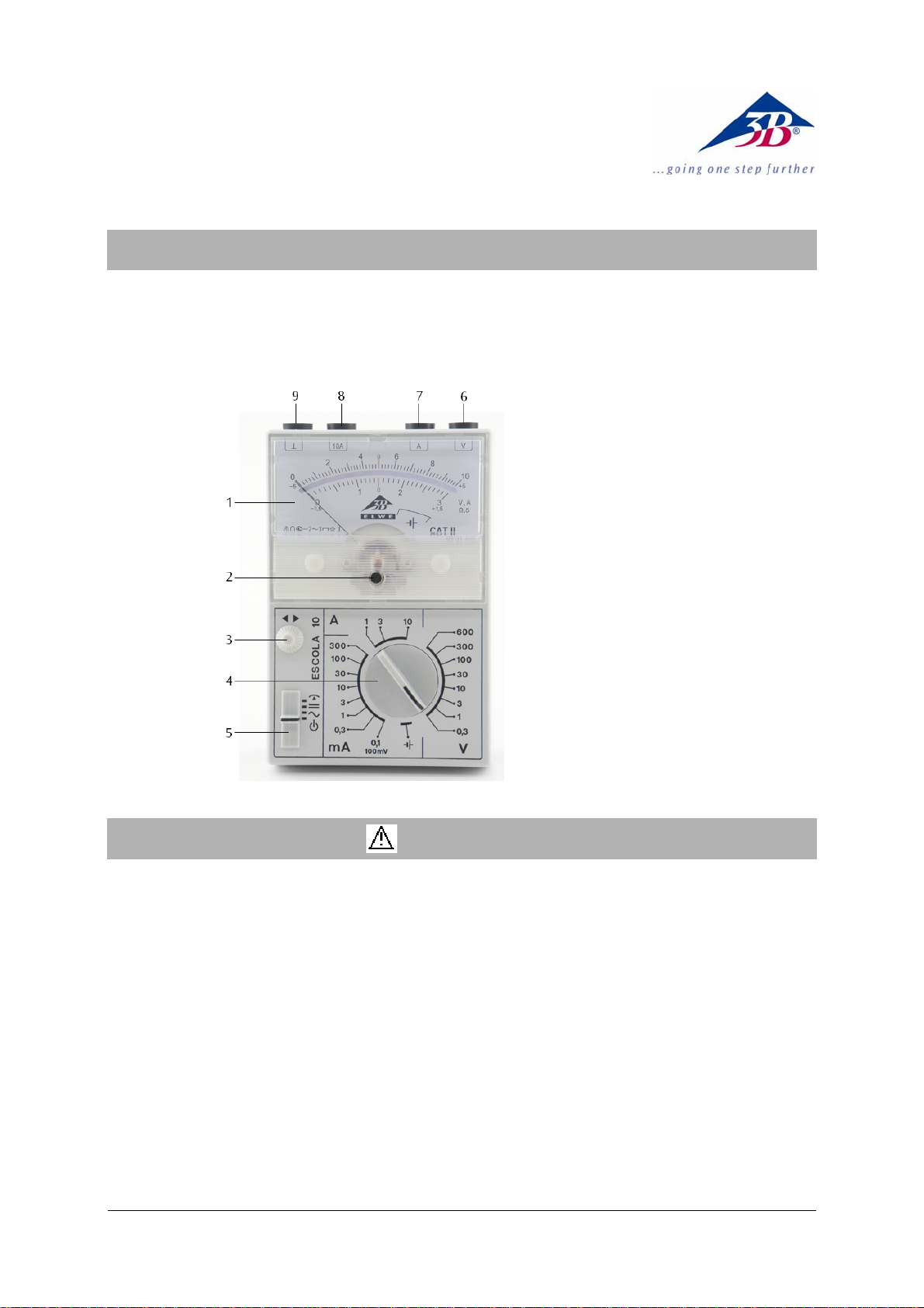
1 Meter display with mirror
scale
2 Slotted screw for zero
calibration
3 Adjustment knob for zero
calibration
4 Measurement range dial
5 Operating mode switch
6 Voltage measurement
socket
7 Current measurement
socket for up to 3 A
8 Current measurement
socket for up to 10 A
9 Safety ground socket
1. Safety instructions
The Escola 10 multimeter conforms to the safety
requirements for electrical equipment for measurement, control and laboratory use in DIN EN
61010 part 1. Safe operation of the apparatus is
guaranteed with correct handling. However, safety
is not guaranteed if the apparatus is handled improperly or carelessly.
• Read this manual carefully before using the
multimeter and follow the instructions!
The multimeter may only be used by people who
are aware of the dangers of electric shock and are
able to take the necessary safety pürecautions.
• Whenever measurements are being made,
in which there is a danger of electric shock,
a second person should always be informed.
• Before using the meter, check the case and
test leads for any damage. In the event of any
malfunction/operational defect or visible damage, do not use the meter. Pay particular attention to the insulation surrounding the
measurement sockets.
• Use with caution when working above 30 V
AC rms, or 60 V DC. Such voltages pose a
shock hazard.
• The limit of the measurement range must
not be exceeded. If the values of the measurand are unknown, always switch from a
higher measurement range to a lower one.
• Do not conduct measurements in a humid
environment. Work area, hands, shoes and
floor must be dry.
• When measuring current, turn off circuit
power before connecting the meter in the
circuit.
1
Page 2
• Connect the common test lead before you
connect the live test lead. When you disconnect test leads, disconnect the live test lead
first.
• Before the case is opened, the meter has to
be switched off and the leads must be disconnected from the meter.
• When disposing empty batteries follow the
local regulations. Never dispose of them in
the regular household garbage.
2. Symbol legend
Read instruction sheet
V Voltage
A Current
Moving coil galvanometer
Apparatus with electronic amplifier
DC quantities accuracy class 2
AC quantities accuracy class 3
Use in horizontal position
2
Test voltage
Use in vertical position
DC quantities
AC quantities
Needle position zero centre
“OFF” position
CAT II Measuring category II is intended for mak-
ing measurements on circuits directly
connected to low-voltage üpwer supplies
(EN 61010-1)
3. Description
The ESCOLA 10 multimeter enables precision
measurements by analogue means in education,
training and practical applications. It measures
AC and DC voltage or current and provides for
measurements with the needle centred on the
dial for DC quantities. Resistance (R) and conductance (G) or impedance (Z) aund admittance
(Y) can be obtained by division.
All measurement ranges are selected by means of
a rotary dial. Two linearised mirror scales, graded in
a 1:3 ratio, guarantee easy readability of the measured values.
The trimmer for setting the zero point in the
centre allows the zero point to be set precisely
when it drifts electrically.
Isolation of the sockets for voltage and current
measurement allow both to be measured in
succession simply by turning the range selector
switch, without any need for reconnecting or
changing the measuring leads.
Use of a robust core-magnet measuring instrument
set-up and an impact resistant casing allows the
instrument to withstand rough handling in awkward
conditions.
The ESCOLA 10 is protected in such a way that
over-loads in the selectable current ranges
automatically cause the power to be limited.
4. Technical data
Measuring category CAT II
Voltage ranges: 0.1; 0.3, 1; 3; 10; 30,
100, 300, 600 V; AC/DC
Current ranges: 0.1; 0.3; 1; 3; 10; 30;
100; 300 mA; 1; 3; 10 A
AC/DC
Input resistance: 1
MΩ AC/DC
Voltage drop for current
measurements: 100 mV AC/DC approx.
Accuracy: DC class 2; AC class 3
Electrical zero
calibration: For all DC ranges
Accuracy for zero
centre: Class 5
Frequency ranges:
1 V – 600 V: 20 Hz…50 Hz
0.3 V: 20 Hz…50 Hz
…20 kHz
…9 kHz
Current ranges: 20 Hz…50 Hz…43 kHz
Scale length: 80 mm
Power supply: 1x 1.5 V, IEC R6 with
test function
Voltage overload ranges: 600 V load in those
voltage ranges for a
lengthy period
Current overload protection ranges (except for
10 A range):
Integral limiting load: 450 A
Surge current limit I
FMS
: 300 A
2
s
Long-term current
limit I
Dimensions: 98 x 148 x 49 mm
: 35 A
FAV
3
Weight: 300 g approx.
2
Page 3

5. Operation
• Switch the device on by select the desired
operating mode,
• To turn off the multimeter, set the mode
switch to the off position
• To test the battery, set the measurement
range dial to the position .
5.1 Current measurement
• Before making any current measurements, set
the mode switch to
ate.
• Connect the terminal at the lower potential
to the earth socket.
• Currents of less than 3 A can be measured
between the earth socket and measuring
socket "A".
• Currents of less than 3 A can be measured
between the earth socket and measuring
socket "A".Currents higher than 3 A should
be measured between the earth socket and
measuring socket "10A".
• Set the switch to
desired measuring range. lf the current to be
measured is unknown beforehand, set the
measurement range dial to the highest
range and work down.
The fact that measurements can be made without disconnecting the instrument and using
overload protection without fuses means that
converters may also be connected into the circuit.
Fig. 1 Current measurement
5.2 Voltage measurement
• Before making any voltage measurements, set
the mode switch to
ate.
• Use the "V" socket on the right for voltage
measurements.
• Set the switch to
desired measuring range. lf the voltage to be
measured is unknown beforehand, set the
, or .
.
or as appropri-
mode and select the
A
A10A
or as appropri-
mode and select the
V
V
measurement range dial to the highest
range and work down.The 100 mV voltage
range is associated with a current range of
0.1 mA.
A10A
Fig. 2 Voltage measurement
5.3 Simultaneous current and voltage
measurement
Isolated current and voltage sockets allow
measure-ments of both current and voltage to
be made in sequence without disconnecting the
measuring leads. That means that in both AC
and DC modes, resistance, conductance, impedance and admittance can all be calculated
forming the appropriate quotients.
A10A
Fig. 3 Simultaneous current and voltage measurement
5.4 Resistance and conductance
According to the defining equation for a linear
resistance, R = U/I, or conductance G = I/U, the
Escola 10 can be connected in circuit as in Fig.
3 so that current and voltage can be measured
one after the other, allowing for resistance
measurements to be made over a range from
mΩ up to several MΩ.
´Therefore conductances in a range from under1
µS up to 30 S can be measured by taking the
reciprocal of the resistance.
One very key advantage of the Escola 10 is that
the instrument, when connected as in Fig. 3, can
measure both current and voltage ranges without having to disconnect it.
5.5 Impedance and admittance
If the circuit in Fig. 3 is powered by a sinusoidal
AC voltage source instead of a DC source, us-
V
V
3
Page 4

ing the definitions for impedance Z = U/I and
admittance Y = I/U means that AC measure-
ments can also be measured in a variety of
ranges in a similar way to the DC quantities in
5.4.
The Escola 10 is particularly useful in this re-
spect because it allows for measurements to be
made not only at 50 Hz, but right across the lowfrequency range.
5.6 Measurements with the zero point of the
needle centred
This kind of measurement can only be made in
DC ranges.
• To make a measurement with the zero point
in the centre, push the mode switch to
• Before measuring the external quantity,
.
calibrate the zero point using the trimmer to
set the point in the direct centre of the scale.
The full extent of the measuring remains available so there is no separate labelling for the
range selector switch.
For a range 0 V ... 10 V, for example, the limits
now become -5 V ... 0 V ... +5 V absolute or 0 V
... ±5 V. Positive values of voltage at the V
socket or current at the A socket cause the needle to move to the right while negative values
cause it to move to the left. The scales are labelled accordingly (smaller auxiliary numbering).
5.7 Changing the battery
5.7.1 General information
• From time to time, check the state of the
battery.
• Remove discharged or corroded bat-
teries from the apparatus.
• During prolonged periods of disuse,
also remove the battery from the apparatus.
• Do not dispose of the battery in the regular
household garbage. Follow the local regulations (In Germany: BattG; EU: 2006/66/EG).
5.7.2 Changing the battery
• Unscrew the back of the chassis.
• Place the negative pole of the battery on the
spring.
The polarity is also marked on the board with
plus and minus symbols. Additionally, a mechanical clip on the positive side prevents battery contact when polarity is reversed.
• Close chassis again.
Fig. 4 Changing the battery
6. Maintenance
• This apparatus does not require special
maintenance.
• For cleaning, use a soft cloth, slightly mois-
tened with alcohol, or a brush.
• In order to remove a potential electrostatic
charge from the meter display window,
which can easily influence measurements,
follow the instructions above.
Dirt or moisture in the measurement sockets can
affect readings.
• Shake out any dirt that may be in the meas-
urement sockets.
• Soak a new swab with isopropyl alcohol and
work around the inside of each measurement socket.
3B Scientific GmbH ▪ Rudorffweg 8 ▪ 21031 Hamburg ▪ Germany ▪ www.3bscientific.com
Subject to technical amendments
© Copyright 2013 3B Scientific GmbH
 Loading...