

Page 1
3B SCIENTIFIC
Electron Diffraction Tube D 1013885
Instruction sheet
07/13 ALF
®
PHYSICS
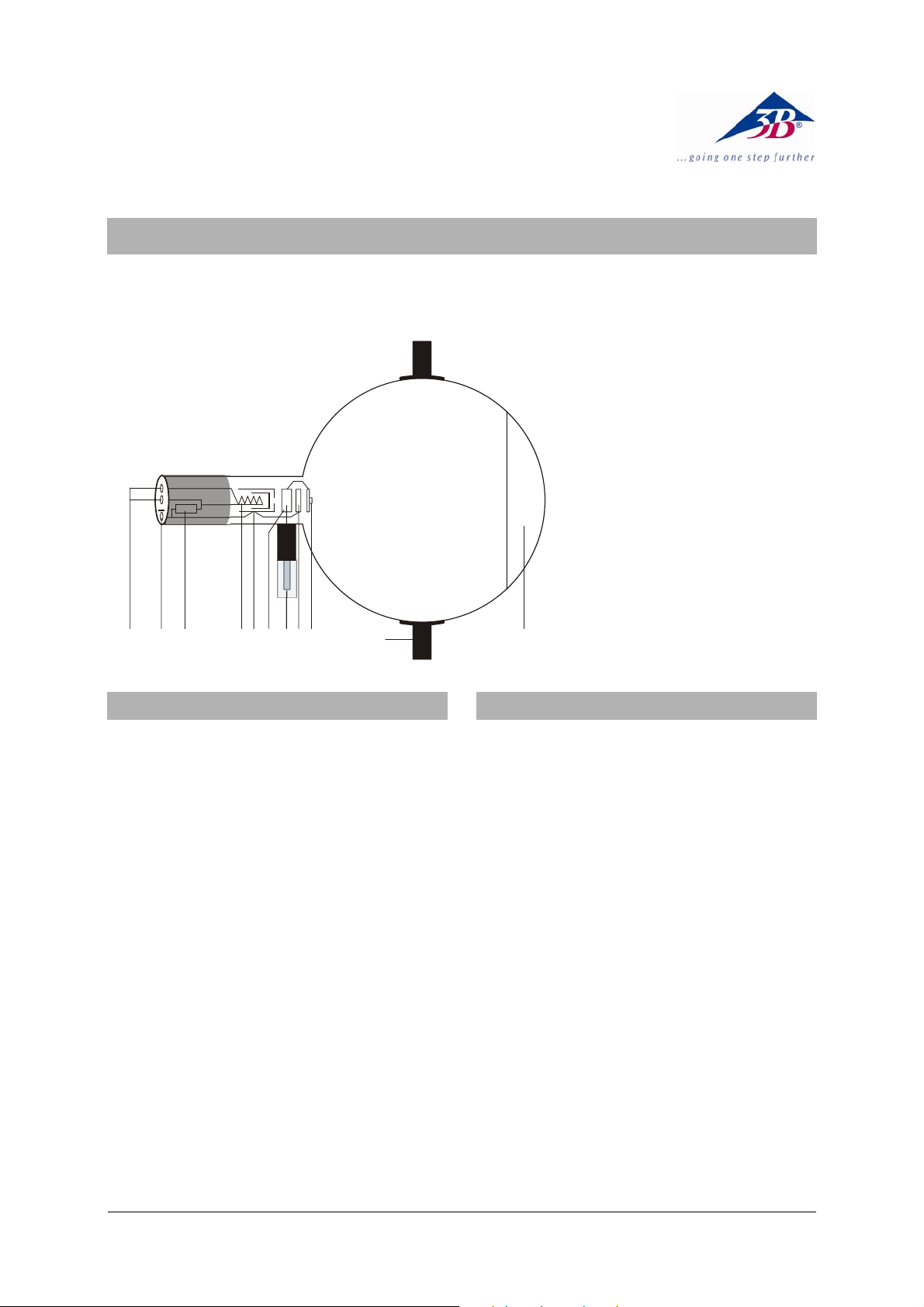
1 4-mm sockets for connecting
heater supply
2 2-mm socket for connecting
cathode
3 Internal resistor
4 Filament
5 Cathode
6 Anode
7 4-mm plug for connecting
anode
8 Focussing electrode
9 Polycrystalline graphite
grating
10 Boss
11 Fluorescent screen
1547
1. Safety instructions
Hot cathode tubes are thin-walled, highly
evacuated glass tubes. Treat them carefully as
there is a risk of implosion.
• Do not subject the tube to mechanical
stresses.
• Do not subject the connection leads to any
tension.
• The tube may only be used with tube holder
D (1008507).
If voltage or current is too high or the cathode is
at the wrong temperature, it can lead to the tube
becoming destroyed.
• Do not exceed the stated operating parame-
ters.
• Only change circuit with power supply
equipment switched off.
• Only exchange tubes with power supply
equipment switched off.
When the tube is in operation, the stock of the
tube may get hot.
• If necessary, allow the tube to cool before
dismantling.
The compliance with the EC directive on electromagnetic compatibility is only guaranteed
when using the recommended power supplies.
62R3
89
10
11
2. Description
The electron diffraction tube illustrates the wave
nature of electrons by allowing observation of
interference caused by a beam of electrons
passing through a polycrystalline graphite target
on a fluorescent screen (Debye-Scherrer diffraction). The wavelength of the electrons can be
calculated for various anode voltages from the
radius of the diffracted rings and the distance
between the crystal layers in the graphite. The
tube also confirms the de Broglie hypothesis.
The electron diffraction tube is a highly evacuated tube with an electron gun consisting of a
pure tungsten heater filament and a cylindrical
anode all contained in a clear glass bulb. The
electrons emitted by the heated cathode are
constrained to a narrow beam by an aperture
and are then focussed by means of an electronoptical system. The resulting tight, monochromatic beam then passes through a micro-mesh
nickel grating situated at the aperture of the gun.
Onto this grid, a thin layer of polycrystalline
graphitised carbon has been deposited by vaporisation. This layer affects the electrons in the
beam much like a diffraction grating. The result
of this diffraction is seen in the form of an image
comprising two concentric rings that become
visible on the fluorescent screen. A spot resulting from the undeflected electron beam continues to be visible at the centre of the rings.
1
Page 2

=
λ
⋅
⋅
A magnet is also supplied with the tube. This
allows the direction of the electron beam to be
changed, which may be necessary if the graphite target has slight damage as a result of the
manufacturing process or due to later overheating.
3. Technical data
Filament voltage: ≤ 7.0 V AC/DC
Anode voltage: 0 – 5000 V DC
Anode current: typ. 0.15 mA
at 4000 V DC
Lattice constant of graphite:
d
d
= 0.213 nm
10
= 0.123 nm
11
Distance from graphite target
to fluorescent screen: 125 ± 2 mm approx.
Fluorescent screen: 100 mm dia. approx.
Glass bulb: 130 mm dia. approx.
Total length: 260 mm dia. approx.
4. Operation
To perform experiments using the electron diffraction tube, the following equipment is also
required:
1 Tube holder D 1008507
1 High voltage power supply 5 kV (115 V, 50/60 Hz)
1003309
or
1 High voltage power supply 5 kV (230 V, 50/60 Hz)
1003310
2 Pair of Experiment Leads, 75 cm 1002850
1 Experiment Lead, Plug and Socket 1002838
Additionally recommended:
1 Protective Adapter, 3-Pole 1009960
2 Pair of Safety Experiment Leads, 75 cm 1002849
1 Experiment Lead, Safety Plug/Socket 1002839
4.1 Setting up the tube in the tube holder
• The tube should not be mounted or removed
unless all power supplies are disconnected.
• Push the jaw clamp sliders on the stanchion
of the tube holder right back so that the jaws
open.
• Push the bosses of the tube into the jaws.
• Push the jaw clamps forward on the stan-
chions to secure the tube within the jaws.
• If necessary plug the protective adapter onto
the connector sockets for the tube.
4.3 General instructions
The graphite foil on the diffraction grating is only
a few layers of molecules thick and any current
greater 0.2 mA can cause its destruction.
The internal resistor is there to prevent damage
to the graphite foil.
The graphite target itself should be monitored
throughout the experiment. If the graphite target
starts to glow, the anode must immediately be
disconnected from its power supply
If the diffraction rings are not satisfactorily visible, the electron beam can be redirected by a
magnet so that it passes through an undamaged
region of the target.
5. Example experiment
• Set u the experiment as in Fig. 2. Connect
the negative pole of the anode supply via
the 2-mm socket.
• Apply the heater voltage and wait about 1
minute for the heater temperature to achieve
thermal stability
• Apply an anode voltage of 4 kV.
• Determine the diameter D of the diffraction
rings.
Two diffraction rings appear on the fluorescent
screen centred on the undeflected beam in the
middle. The two rings correspond to Bragg reflections from atoms in the layers of the graphite
crystal lattice.
Changing the anode voltage causes the rings to
change in diameter. Reducing the voltage
makes the rings wider. This supports de
Broglie's postulate that the wavelength increases as momentum is reduced.
a) Bragg equation:
λ = wavelength of the electrones
ϑ = glancing angle of the diffraction ring
d = lattice plane spacing in graphite
L = distance between sample and screen
D = diameter D of the diffraction ring
R = radius of the diffraction ring
D
=ϑ22tan
L
b) de-Broglie equation:
h = Planck’s constant
p = momentum of the electrones
2
p
2
m
=⋅
Ue
m = electron mas, e = electron charge
4.2 Removing tube from the tube holder
• To remove the tube, push the jaw clamps
right back again and take the tube out of the
jaws.
ϑ⋅⋅
sin2 d
R
d ⋅=λ
L
h
=λ
p
h
Uem
⋅⋅⋅=λ2
2
Page 3

D
Fig. 1 Schematic representation to Debye-Scherrer diffraction
L
DC POWER SUPPLY 0 ... 5 kV
3
2
4
1
0
R
KV
U
F
U
5
0 ... 5 kV
A
2 mm
Fig. 2 Circuit of the diffraction tube D
Fig. 3 Circuit of the diffraction tube D with protective adapter, 3-pole (1009960)
A TELTRON Product from UK3B Scientific Ltd. ▪ Suite 1 Formal House, Oldmixon Crescent ▪ Weston-super-Mare
Somerset BS24 9AY ▪ Tel 0044 (0)1934 425333 ▪ Fax 0044 (0)1934 425334 ▪ e-mail uk3bs@3bscientific.com
Technical amendments are possible
© Copyright 2013 3B Scientific GmbH
Page 4

 Loading...