

Page 1
3B SCIENTIFIC® PHYSICS
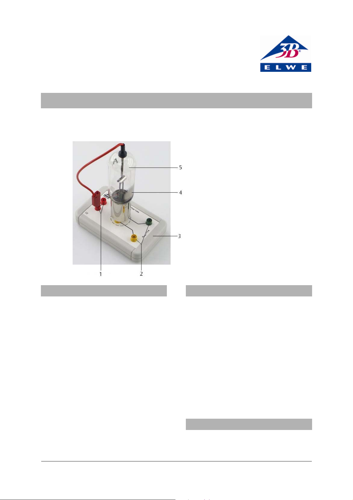
Dual Pole Tube U8482360
Instruction Sheet
10/10 LT/ALF
1 Anode terminal
2 Sockets for heater voltage
3 Base
4 Getter
5 Dual pole tube
1. Safety Instructions
When the instrument is used in accordance with the
instructions and regulations, safe operation is ensured.
However, safety is not guaranteed if the instrument has
been treated inappropriately or carelessly.
If there is reason to believe that safe operation is
no longer possible (e.g., if there is visible damage),
the instrument must not be used, or if in use it
must be taken out of service immediately.
Excessive voltages or currents or an incorrect
cathode temperature can damage the tube
irreparably.
• Keep within the specified operating
parameters.
• Do not apply a heater voltage greater than 5 V.
When the tube is being operated, there may be
dangerously high voltages in the area of the connections.
• Only use safety experiment leads for the
connections.
• Only make connections when the voltage
supply is switched off.
The instrument is not suitable for student experiments.
2. Description
The dual pole tube is used for demonstrating the
Edison effect, for confirming the Richardson
equation, and for measuring the current/voltage
characteristic (I
curve) of a diode.
A/UA
The electrode system, consisting of a tungsten
cathode and a cylindrical anode of sheet nickel, is
housed in an evacuated glass bulb. The heating
current for the tungsten cathode can be varied
within the electron-emitting range. The anode
connection is safe to handle and is mechanically
fixed to the glass bulb.
The tube also incorporates another system (the
getter), which serves to generate a high vacuum
during the manufacture of the tube, and is not
relevant to the functioning of the instrument.
3. Equipment supplied
1 Dual pole tube
1 Tube base with safety connection sockets
1 Instruction sheet
1
Page 2
4. Technical data
Cathode area: approx. 32 mm²
Max. anode voltage: 400 V
Heater voltage: 1.5 – 5 V
Heater current: 2 – 5 A
Tube dimensions: approx. 120×45 mm²
Overall dimensions: approx. 170x105x230mm³
Weight: approx. 370 g
5. Operation
• Carefully push the tube into the two middle
sockets of the base and connect the anode lead
Fig. 1b Circuit connection of the 500 V DC power
to one of the two red sockets, which are
connected together internally.
The remaining socket (1) allows an external
connection to the anode of the tube.
6. Sample experiments
For carrying out the experiments, the following
additional equipment is needed:
1 DC power supply, 500 V (230 V, 50/60 Hz)
U33000-230
or
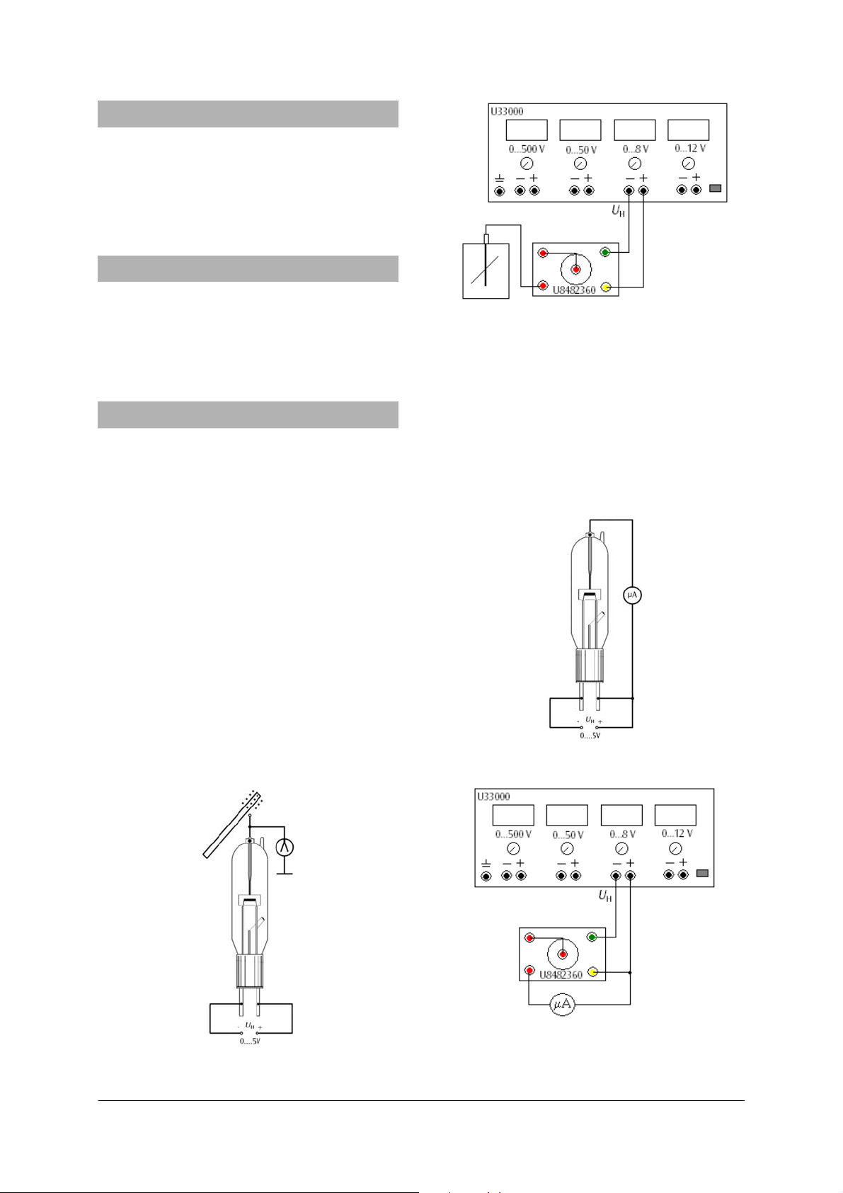
In a second experiment the effect is demonstrated
using a multimeter.
• Connect the circuit as shown in Fig. 2a/b.
The multimeter shows a current of about 85 µA (the
“Edison current”), as the tungsten filament at a high
temperature emits electrons. Between the negative end
of the heater coil and the anode there is a difference of
+3 V, producing an electric field which accelerates the
electrons so that they reach the anode.
1 DC power supply, 500 V (115 V, 50/60 Hz)
U33000-115
1 Digital multimeter U118091
1 Electroscope U85321301
6.1 Demonstration of the Edison effect
In this reproduction of a historic experiment, the
Edison effect is observed by means of an
electroscope connected to the anode.
• Connect the circuit as shown in Fig. 1a/b.
• Transfer the positive charge of a rubbed glass
rod to the anode and electroscope.
The charge remains present until the cathode of
the tube is activated by heating. The electron
deficit is then neutralised by the electrons emitted
from the cathode. The anode becomes discharged.
Fig. 2a Circuit set-up for demonstrating the Edison
supply (U33000)
effect using a multimeter
Fig. 1a Circuit set-up for demonstrating the Edison
effect using an electroscope
Fig. 2b Circuit connection of the 500 V DC power
supply (U33000)
2
Page 3

6.2 Measuring the current/voltage characteristic
(I
curve) of a diode
A/UA
Figure 5 shows the different regions of a typical
curve, which can be measured using two circuits.
The cutoff region (Sp) and the current onset region
(A) are measured by applying a negative anode
voltage, which is progressively reduced up to the
beginning of the space-charge region (R). This part
of the measurement ends with U
• For the latter regions, connect the circuit as
= 0 V.
A
shown in Figures 3a/b.
• Determine how the anode current I
on the anode voltage U
by decreasing the
A
depends
A
anode voltage step by step from -8 V to 0 V.
• Plot the values of I
and UA on a graph.
A
Fig. 4a Circuit set-up for measuring the space-charge
and saturation regions
Fig. 3a Circuit set-up for measuring the current onset
region
Fig. 3b Circuit connection of the 500 V DC power
supply (U33000)
The space-charge region (R) and the saturation
region (S) of the curve are measured by applying a
positive anode voltage that is varied over the range
0…250 V.
• Connect the circuit as shown in Figures 4a/b.
• Determine how the anode current I
on the anode voltage U
by raising the anode
A
depends
A
voltage step by step from 0 V to 250 V.
• Plot the values of I
and UA on a graph.
A
Fig. 4b Circuit connection of the 500 V DC power
supply (U33000))
Fig. 5 Current/voltage characteristic of a diode
Elwe Didactic GmbH • Steinfelsstr. 6 • 08248 Klingenthal • Germany • www.elwedidactic.com
3B Scientific GmbH • Rudorffweg 8 • 21031 Hamburg • Germany • www.3bscientific.com
Technical amendments are possible
© Copyright 2010 3B Scientific GmbH
Page 4

 Loading...