

Page 1
3B SCIENTIFIC® PHYSICS
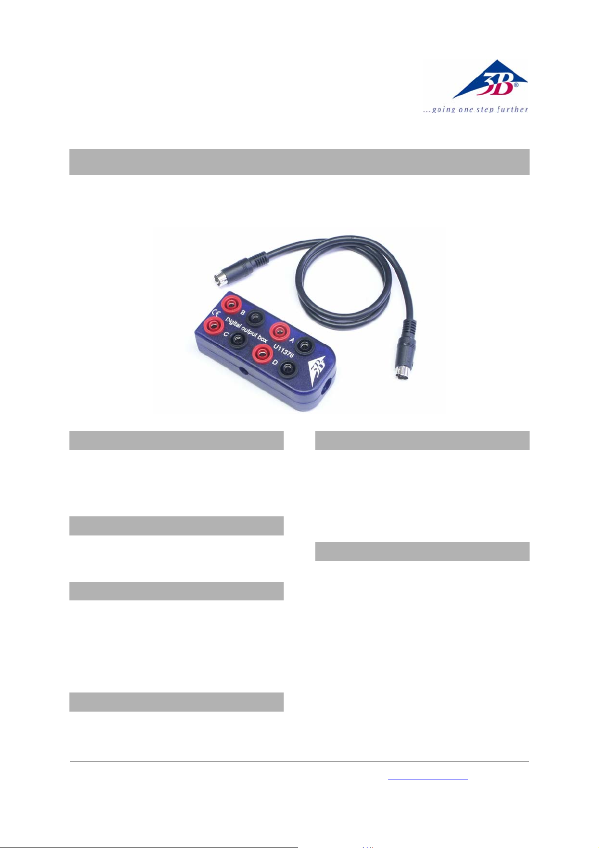
Digitale Ausgangsbox U11376
Bedienungsanleitung
08/10 Hh
1. Sicherheitshinweise
• Die Digitale Ausgangsbox nur an der
3B NETlog
TM
-Buchse „Digital Outputs“ verwenden! Für eine Verwendung an den digitalen
Eingängen ist sie nicht korrekt beschaltet!
2. Lieferumfang
1 Digitale Ausgangsbox
1 miniDIN-Anschlusskabel 8-pin, 60 cm lang
3. Beschreibung
Die digitale Ausgangsbox dient zur Auffächerung
der vier digitalen 3B NETlog
TM
-Interfaceausgänge A /
B / C / D auf acht 4 mm-Sicherheitsbuchsen.
An den roten Buchsen kann das Digitalsignal im
TTL-Pegel entnommen werden; Die blauen Buchsen sind am Masse-Bezugspotenzial angeschlossen.
4. Technische Daten
Ausgangssignal: 5 V-TTL-Pegel, kurzschlussfest
Fan out
(Auffächerung eines Ausgangs): 2 x TTL-Eingang
5. Bedienung
• Digitale Ausgangsbox mit dem beigefügten
miniDIN-Kabel an der Buchse „Digital Outputs“
des 3B NETlog
Das Digitalsignal kann mit verschiedenen Ereignissen in der 3B NETlab
TM
anstecken.
TM
-Software verknüpft oder
auch entsprechend direkt ausgewählt werden.
6. Versuchsbeispiel
Übersteuerungs- / Untersteuerungssignal in Abhängigkeit von den Vergleichsspannungen an den
beiden Analogeingängen A und / oder B aufgrund
eines wählbaren Schwellenwertes
Aufbau eines diskreten Digital- / Analog-Wandlers
(DAC) mit gestuften Widerständen nach dem R / 2RVerfahren
Programmierte Ablaufsteuerungen im Sinne einer
4 Bit-Speicherprogrammierbaren Steuerung (SPS,
PLC), z.B. für einen Schrittmotor
3B Scientific GmbH • Rudorffweg 8 • 21031 Hamburg • Deutschland • www.3bscientific.com
Technische Änderungen vorbehalten
© Copyright 2010 3B Scientific GmbH
Page 2

Page 3

3B SCIENTIFIC® PHYSICS
Digital output box U11376
Instruction sheet
08/10 Hh
1. Safety instructions
• Connect the digital output box to the
3B NETlog
TM
“Digital Outputs” socket only. The
wiring is not suitable for connection to the
digital inputs.
2. Scope of delivery
1 Digital output box
1 Mini DIN connecting lead 8-pin, 60 cm length
3. Description
The digital output box fans out the four
3B NETlog
TM
digital interface outputs A/B/C/D to
eight 4-mm safety sockets.
The digital signal can be read from the red sockets
as a TTL output. The blue sockets are connected to
ground.
4. Technical data
Output signal: 5 V TTL level, short-circuit-protected
Each digital output is fanned out to 2 x TTL inputs
on the digital output box
5. Operation
• Connect the digital output box to the “Digital
Outputs” socket of the 3B NETlog
TM
equipment
using the included mini DIN lead.
The digital signal can be linked to various events in
the 3B NETlab
TM
software, or it can be selected
directly.
6. Sample experiment
High and low control signals relative to voltage
levels at analog inputs A and B that are adjusted to
provide an arbitrary comparator threshold.
Construction of a binary weighted digital-toanalogue converter (DAC) with an R-2R ladder resistor ladder.
Programmable logic control using 4-bit programmable logic (PLC), e.g. for a stepper motor
3B Scientific GmbH • Rudorffweg 8 • 21031 Hamburg • Germany • www.3bscientific.com
Subject to technical amendments
© Copyright 2010 3B Scientific GmbH
Page 4

Page 5

3B SCIENTIFIC® PHYSICS
Boîte de sortie numérique U11376
Instructions d’utilisation
08/10 Hh
1. Consignes de sécurité
• N'utilisez la boîte de sortie numérique qu'avec
la douille « Digital Outputs » du 3B NETlog
TM
!
Son câblage ne permet pas un emploi aux entrées numériques !
2. Matériel fourni
1 boîte de sortie numérique
1 câble de connexion mini-Din à 8 broches, 60 cm
de long
3. Description
La boîte de sortie numérique permet de répartir les
quatre sorties d'interface numériques 3B NETlog
TM
A /
B / C / D sur quatre douilles de sécurité de 4 mm.
Le signal numérique au niveau TTL peut être préle-
vé sur les douilles rouges. Les douilles bleues sont
connectées au potentiel de référence de la masse.
4. Caractéristiques techniques
Signal de sortie : niveau TTL 5 V, résistant aux
courts-circuits
Fan out (répartition d'une sortie) : 2 entrées TTL
5. Manipulation
• Branchez la boîte de sortie numérique avec le
câble mini-Din fourni à la douille « Digital
Outputs » du 3B NETlog
Le signal numérique peut être corrélé à différents
événements dans le logiciel 3B NETlab
TM
.
TM
ou sélec-
tionné directement.
6. Exemples d'expérience
Signal de surréglage / sous-réglage en fonction des
tensions de comparaison aux deux entrées analogiques A et / ou B sur la base d'une valeur seuil
réglable.
Montage d'un convertisseur numérique / analogique (CNA) discret avec résistances étagées selon le
procédé R / 2R.
Traitements séquentiels programmés dans le sens
d'un automate programmable à 4 bits (API, PLC),
par ex. pour un moteur pas à pas.
3B Scientific GmbH • Rudorffweg 8 • 21031 Hamburg • Allemagne • www.3bscientific.com
Sous réserve de modifications techniques
© Copyright 2010 3B Scientific GmbH
Page 6

Page 7

3B SCIENTIFIC® PHYSICS
Scatola di uscita digitale U11376
Istruzioni per l'uso
08/10 Hh
1. Norme di sicurezza
• Utilizzare la scatola di uscita digitale solo sulla
presa 3B NETlog
TM
"Digital Outputs"! Essa non è
cablata in modo corretto per l'utilizzo sugli
ingressi digitali!
2. Fornitura
1 scatola di uscita digitale
1 cavo di collegamento miniDIN da 8 pin, lungh. 60 cm
3. Descrizione
La scatola di uscita digitale serve per il fan-out
delle quattro uscite digitali A/B/C/D dell'interfaccia
3B NETlog
TM
su otto jack di sicurezza da 4 mm.
Sulle prese rosse è possibile prelevare il segnale
digitale nel livello TTL, mentre le prese blu sono
collegate al potenziale di massa di riferimento.
4. Dati tecnici
5. Comandi
• Collegare la scatola di uscita alla presa "Digital
Outputs" di 3B NETlog
TM
con il cavo miniDIN
fornito in dotazione.
Il segnale di uscita può essere collegato a diversi
eventi nel software 3B NETlab
TM
oppure anche
essere selezionato direttamente.
6. Esempi di esperimenti
Segnale di sovramodulazione/sottomodulazione in
funzione delle tensioni comparative su entrambi
gli ingressi analogici A e/o B in base ad un valore
soglia selezionabile.
Struttura di un trasduttore digitale/analogico
discreto (DAC) con resistenze a gradini secondo il
procedimento R/2R.
Controlli sequenziali programmati tramite
controller a 4 bit a logica programmabile (PLC), ad
es. per un motore passo-passo.
Segnale di uscita: livello TTL 5 V, resistente
a cortocircuito
Fan-out
(carico elettrico di un'uscita): 2 x ingresso TTL
3B Scientific GmbH • Rudorffweg 8 • 21031 Amburgo• Germania• www.3bscientific.com
Con riserva di modifiche tecniche
© Copyright 2010 3B Scientific GmbH
Page 8

Page 9

3B SCIENTIFIC® PHYSICS
Caja de salidas digitales U11376
Instrucciones de uso
08/10 Hh
1. Advertencias de seguridad
• ¡La caja de salidas digitales se debe utilizar sólo
en el casquillo "Digital Outputs“ del 3B NETlog
TM
!
La caja no tiene un cableado adecuado para la
utilización en las entradas digitales!!
2. Volumen de entrega
1 Caja de salidas digitales
1 Cable de conexión miniDIN de 8 pines, 60 cm de largo
3. Descripción
La caja de salidas digitales sirve para repartir las
cuatro salidas de interface A / B / C / D digitales del
3B NETlog
TM
en ocho casquillos de seguridad de 4
mm.
En los casquillos rojos se pueden tomar señales
digitales de nivel TTL; los azules están conectados
al potencial de referencia de masa.
4. Datos técnicos
Señal de salida: Nivel TTL de 5 V, protegido
contra cortocircuito.
Fan out
(Repartición de una salida): 2 x Entradas TTL
5. Manejo
• Se enchufa la caja de salidas digitales en la
salida “Digital Outputs“ del 3B NETlog
TM
utilizando en cable miniDIN que acompaña a
la unidad.
La señal digital se puede correlacionar con
diferentes eventos en el software del 3B NETlab
TM
o
también seleccionar directamente.
6. Experimento ejemplar
Señal de sobreexcitación resp. de excitación
insuficiente en dependencia con las tensiones de
comparación en ambas entradas analógicas A y/o B
en base a un valor de umbral que se puede
seleccionar.
Montaje de un convertidor Analógico/Digital
discreto con resistencias escalonadas según el
procedimiento R / 2R
Controles secuenciales programables según un
control lógico programable de 4 Bits para un motor
de paso paso (PLC).
3B Scientific GmbH • Rudorffweg 8 • 21031 Hamburgo •Alemania • www.3bscientific.com
Nos reservamos el derecho a cambios técnicos
© Copyright 2010 3B Scientific GmbH
Page 10

Page 11

3B SCIENTIFIC® PHYSICS
Caixa de saída digital U11376
Instruções para o uso
08/10 Hh
1. Indicações de segurança
• A caixa de saída digital só deve ser utilizada no
conector " Digital Outputs " do 3B NETlog
TM
! Ela
não está corretamente conectada para uma
utilização nas entradas digitais!
2. Fornecimento
1 caixa de saída digital
1 cabo miniDIN de 8 pin, 60 cm de comp.
3. Descrição
A caixa de saída digital serve para a distribuição
das quatro saídas de interface digitais A / B / C / D
do 3B NETlog™ para oito conectores de segurança
de 4 mm.
Nos conectores vermelhos pode ser recebido o sinal
digital no nível TTL; os conectores azuis estão
ligados ao potencial de referência de massa.
4. Dados técnicos
5. Utilização
• Ligar a caixa de saída digital com o cabo
miniDIN incluído no fornecimento no conector
„Digital Outputs“ do 3B NETlog
O sinal digital pode ser interligado com diferentes
eventos no software da 3B NETlab
TM
.
TM
ou estes
podem ser diretamente selecionados.
6. Exemplos de experiências
Sinal de sobrecontrole/subcontrole em função das
tensões de comparação em ambas entradas
analógicas A e / ou B por causa de um valor limite
selecionável.
Montagem de um transmutador discreto
digital/analógico (DAC) com resistências com
patamares conforme o procedimento R / 2R.
Controle programado de processo no sentido de
um controle programável por memória de 4 Bit
(SPS, PLC), por exemplo, para um motor de passo.
Sinal de saída: 5 V - nível TTL, anti-curto
Fan out
(distribuição de uma saída): 2 x entrada TTL
3B Scientific GmbH • Rudorffweg 8 • 21031 Hamburgo • Alemanha • www.3bscientific.com
Sob reserva de alterações técnicas
© Copyright 2010 3B Scientific GmbH
Page 12

 Loading...