

Page 1
3B SCIENTIFIC® PHYSICS
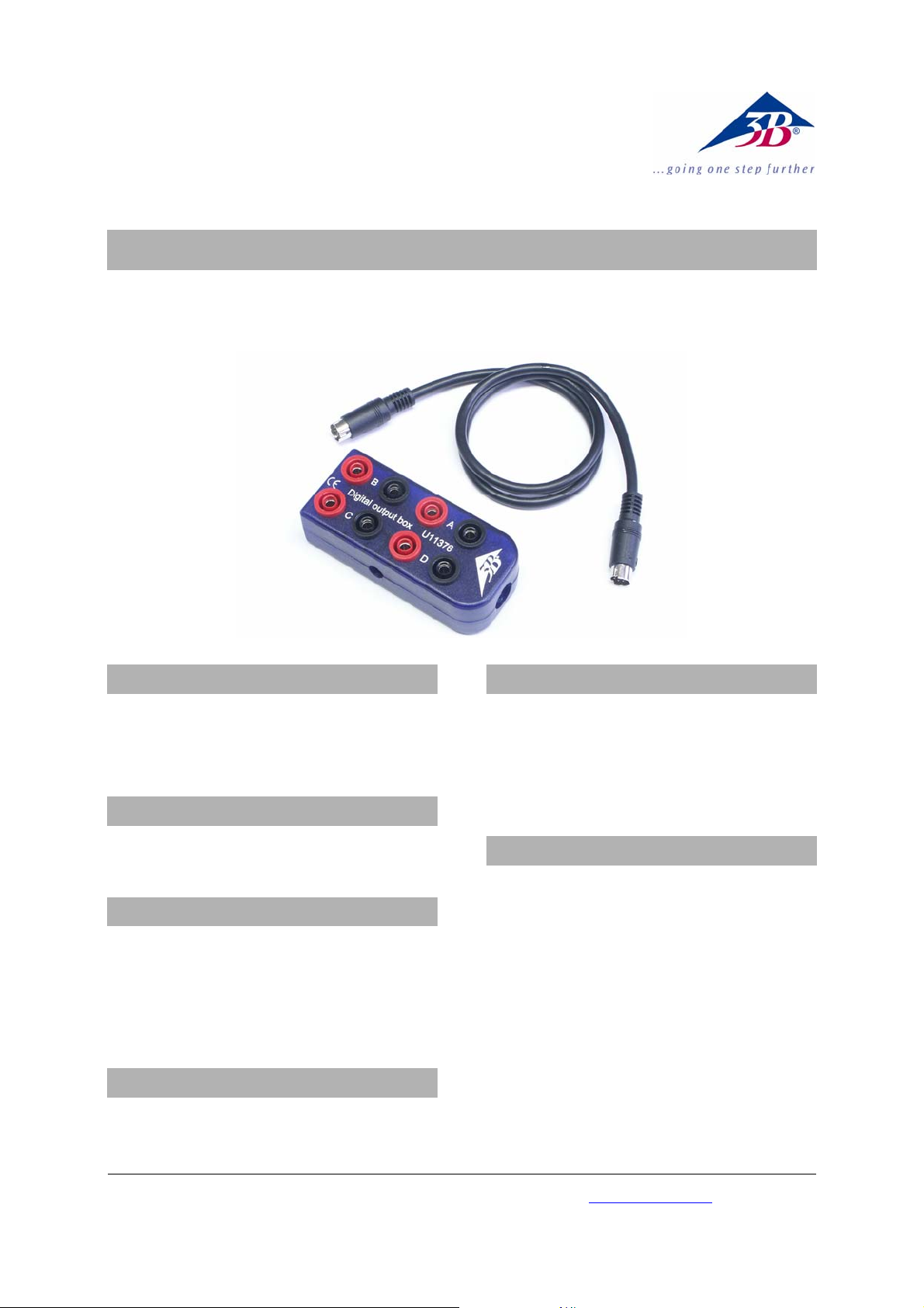
Digital output box U11376
Instruction sheet
08/10 Hh
1. Safety instructions
• Connect the digital output box to the
3B NETlog
TM
“Digital Outputs” socket only. The
wiring is not suitable for connection to the
digital inputs.
2. Scope of delivery
1 Digital output box
1 Mini DIN connecting lead 8-pin, 60 cm length
3. Description
The digital output box fans out the four
3B NETlog
TM
digital interface outputs A/B/C/D to
eight 4-mm safety sockets.
The digital signal can be read from the red sockets
as a TTL output. The blue sockets are connected to
ground.
4. Technical data
Output signal: 5 V TTL level, short-circuit-protected
Each digital output is fanned out to 2 x TTL inputs
on the digital output box
5. Operation
• Connect the digital output box to the “Digital
Outputs” socket of the 3B NETlog
TM
equipment
using the included mini DIN lead.
The digital signal can be linked to various events in
the 3B NETlab
TM
software, or it can be selected
directly.
6. Sample experiment
High and low control signals relative to voltage
levels at analog inputs A and B that are adjusted to
provide an arbitrary comparator threshold.
Construction of a binary weighted digital-toanalogue converter (DAC) with an R-2R ladder resistor ladder.
Programmable logic control using 4-bit programmable logic (PLC), e.g. for a stepper motor
3B Scientific GmbH • Rudorffweg 8 • 21031 Hamburg • Germany • www.3bscientific.com
Subject to technical amendments
© Copyright 2010 3B Scientific GmbH
Page 2

 Loading...