

Page 1
3B SCIENTIFIC
Digital Multimeter E 1006809
Instruction sheet
05/12 ALF
®
PHYSICS
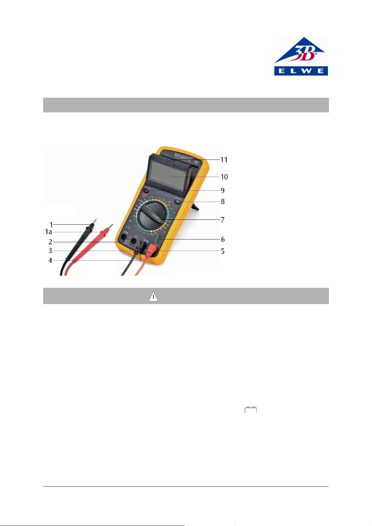
1 Measuring probe
1a Finger guards
2 Measurement socket “20 A“for
current measurement 20 A
range (plus)
3 Measurement socket “A” for
current measurement for up to
2 A (plus)
4 Measurement socket “COM“
(minus)
5 Measurement socket “V/Ω“ for
voltage and resistance meas-
urement (plus)
6 Transistor test socket
7 Measurement range dial
8 Button Hold function
9 On/Off switch
10 Display
11 Unlock button
!
1. Safety instructions
The Digital Multimeter E conforms to the safety
requirements for electrical equipment for measurement, control and laboratory use in DIN EN
61010 part 1. Safe operation of the apparatus is
guaranteed with correct handling. However,
safety is not guaranteed if the apparatus is handled improperly or carelessly.
• Read this manual carefully before using the
digital multimeter and follow the instructions!
• Before using the meter, check the case and
test leads for any damage. In the event of
any malfunction/operational defect or visible
damage, do not use the meter. Pay particular attention to the insulation surrounding the
measurement sockets.
• Use with caution when working above 30 V
ACrms, or 60 V DC. Such voltages pose a
shock hazard.
• The limit of the measurement range must
not be exceeded. If the values of the measurand are unknown, always switch from a
higher measurement range to a lower one.
• When measuring current, turn off circuit
power before connecting the meter in the
circuit.
• Connect the common test lead before you
connect the live test lead. When you disconnect test leads, disconnect the live test lead
first.
• When using the measuring probes, keep
your fingers behind the finger guards on the
probes.
• Do not operate the meter around explosive
gas, vapour, or dust.
• Do not conduct measurements in a humid
environment. Work area, hands, shoes and
floor must be dry.
• To avoid false readings, which could lead to
possible electric shock or personal injury,
replace the batteries as soon as the low bat-
tery indicator (
• Before the case is opened, the meter has to
be switched off and the leads must be disconnected from the meter.
• Never use the meter when the case is open.
• When disposing empty batteries follow the
local regulations. Never dispose of them in
the regular household garbage.
+ -
) appears.
1
Page 2
2. Symbol legend
!
Read instruction sheet
Dangerous voltages
V DC voltage
A DC current
V AC voltage
A AC current
Diode and continuity test
hFE Current amplifying factor of a transistor
Ω Resistance
+ -
Empty battery
3. Description
The Digital Multimeter E is a robust, battery
operated multimeter with a 3½-digit LCD display
for measuring voltage, current and resistance as
well as for diode and hFE gain testing.
All measurement ranges are selected by means
of a rotary dial. All measurement ranges are
protected against overload except the 20 A
range.
The meter is equipped with a hold function,
negative polarity indication, over range indication, low battery indication and automatic switch
off after 15 minutes. After the power is automatically switched off it needs to be turned off and
turned on again to continue the power.
The digital display is folding for ease of reading
and on the backside there is a fold out prop for
standing the device on a table.
4. Equipment supplied
1 Digital multimeter
1 Pair of measuring probes
1 Battery
1 Instruction manual
5. Technical data
General specifications
Display: 3½- display LCD,
24 mm, max. 1999
Operating voltage: 9 V battery 6F22
Fuse: F2A/250 V
Measurement rate: 2 - 3 / sec
Operating temperature: 0°C - 40°C, 0 - 75%
R.H.
Storage temperature: -10°C - 50°C, 0 - 75%
R.H.
Safety classification: CAT II
Dimensions: 85x185x35 mm
3
approx.
Weight: 310 g approx. (including
battery)
Electrical specifications
V
Measuring range Accuracy
200 mV ±0.5 % ± 3 digits
2 V, 20 V, 200 V ±0.8 % ± 2 digits
1000 V ±1.0 % ± 2 digits
DC voltage
Input impedance: 10 MΩ
V
Measuring range Accuracy
200 mV ±1.2 % ± 5 digits
2 V, 20 V, 200 V ±1.0 % ± 5 digits
750 V ±1.2 % ± 5 digits
AC voltage
Input impedance: 10 MΩ
Frequency range: 40 – 400 Hz
A
Measuring range Accuracy
20 µA ±1.8 % ± 2 digits
200 µA, 2 mA, 2 mA
20 mA, 200 mA
2 A, 20 A ±2.0 % ± 10 digits
DC current
Measuring voltage drop: 200 mV
±2.0 % ± 2 digits
2
Page 3

!
!
!
A
Measuring range Accuracy
20 µA, 200 µA, 2 mA
20 mA
±2.0 % ± 3 digits
200 mA ±2.0 % ± 5 digits
2 A, 20 A ±2.5 % ± 10 digits
AC current
Measuring voltage drop: 200 mV
Frequency range: 40 – 400 Hz
Ω
Measuring range Accuracy
200 Ω ±1.0 % ± 10 digits
2 kΩ, 20 KΩ, 200 kΩ
2 MΩ
20 MΩ ±1.0 % ± 10 digits
Accuracy is given for 1 year after calibration at
23°C ±5°C, RH<75%.
6.1 Method of measurement
Warning! Dangerous voltages may be
present at the Input terminals and may not be
displayed.
6.1.1 Voltage measurement
• Set the measurement range dial at the re-
quired position
• Connect the black test lead to the meas-
urement socket "COM" and the red test lead
to the "V/Ω" socket. The meter is connected
parallel to the measuring point. The polarity
of the red lead connection will be indicated
at the same time as the voltage.
Note
• lf the voltage to be tested is unknown be-
forehand, set the measurement range dial to
the highest range and work down.
• When only the figure "1" is displayed, over
range is being indicated and the measurement range dial has be set to a higher
range.
• Never measure voltages higher than 1000 V.
6.1.2 Current measurement
• Set the measurement range dial at the re-
quired position
• Connect the black test lead to the meas-
urement socket "COM" and the red test lead
to the "A" socket for measurements up to
±1.0 % ± 4 digits
6. Operation
or .
or .
2 A. For measurements over 2 A connect it
to the socket “20A”. The meter is connected
in series to the measuring object. The polarity of the red lead connection will be indicated at the same time as the current.
Note
• lf the current to be tested is unknown be-
forehand, set the measurement range dial to
the highest range and work down.
• When only the figure "1" is displayed, over
range is being indicated and the measurement range dial has be set to a higher
range.
• Limit measurements inthe 20A range to
max. 15 s.
6.1.3 Resistance measurement
Warning! To avoid electrical shock or
damage to the meter when measuring resistance in a circuit, make sure the power to the
circuit is turned off and all capacitors are discharged.
• Set the measurement range dial to the Ω
range.
• Connect the black test lead to the meas-
urement socket "COM" and the red test lead
to the "V/Ω" socket. Measurement is done
parallel to the resistor
Note
• lf the resistance to be tested is unknown
beforehand, set the measurement range dial
to the highest range and work down.
• When only the figure "1" is displayed, over
range is being indicated and the measurement range dial has be set to a higher
range.
When the input is not connected, i.e. at open
circuit, the figure "1" will be displayed for the
over range conditlon.
6.1.4 Diode test
• Set the measurement range dial to .
• Connect the black test lead to the meas-
urement socket "COM" and to the cathode of
the diode. Connect the red test lead to the
"V/Ω" socket and the anode of the diode.
Note
When the input is not connected, i.e. at open
circuit, the figure "1" will be displayed
The meter displays the forward voltage drop and
displays figure "1" for overload when the diode
is reversed.
6.1.5 Continuity test
Warning! To avoid electrical shock or
damage to the meter when measuring continuity
in a circuit, make sure the power to the circuit is
turned off and all capacitors are discharged.
• Set the measurement range dial to .
3
Page 4

•
Connect the black test lead to the measurement socket "COM" and the red test lead
to the "V/Ω" socket.
A built-In buzzer sounds if the resistance is less
than 30 ± 10 Ω.
6.1.6 Transistor hFE test
• Set the measurement range dial to hFE.
• Make sure the transistor is "NPN" or "PNP"
type. Insert the transistor correctly into the
corresponding transistor test socket.
Display reading is approx. transistor hFE value.
Base current approx. 10 µA, V
approx.2.8 V.
CE
6.2 LCD Display panel angle selection
LCD display panel is locked in lie down position
in normal operating condition and storage.
• To change the display panel angle, push
down the button which is above the top
case, and release lock.
• Rotate the display panel to the best angle.
6.3 Battery and fuse replacement
• Battery and fuse replacement should only be
done after the test leads have been disconnected and power is off.
• Loosen screws with suitable screwdriver and
remove case bottom.
• Replace the battery resp. the fuse.
• Replace the case bottom and reinstall the
three screws. Never operate the meter
unless the case bottom is fully closed.
7. Maintenance
Beyond replacing batteries and fuses, do not
attempt to repair or service your meter unless
you are qualified to do so and have the relevant
calibration, performance test, and service instructions.
• Turn off the meter and remove the test leads
before you service or clean the device.
• Periodically wipe the case with a damp cloth
and mild detergent.
• Do not use abrasives or solvents.
Dirt or moisture in the measurement sockets can
affect readings.
• Shake out any dirt that may be in the meas-
urement sockets.
• Soak a new swab with isopropyl alcohol and
work around the inside of each measurement socket.
8. Disposal
• The packaging should be disposed of at
local recycling points.
• Do not dispose of the battery in the regular
household garbage. Follow the local regulations.
• Should you need to dispose of the equip-
ment itself, never throw it away in normal
domestic waste. Local regulations for the
disposal of electrical equipment will apply.
Elwe Didactic GmbH ▪ Steinfelsstr. 5 ▪ 08248 Klingenthal ▪ Germany ▪ www.elwedidactic.com
3B Scientific GmbH ▪ Rudorffweg 8 ▪ 21031 Hamburg ▪ Germany ▪ www.3bscientific.com
Subject to technical amendments
© Copyright 2012 3B Scientific GmbH
 Loading...