

Page 1
3B SCIENTIFIC® PHYSICS
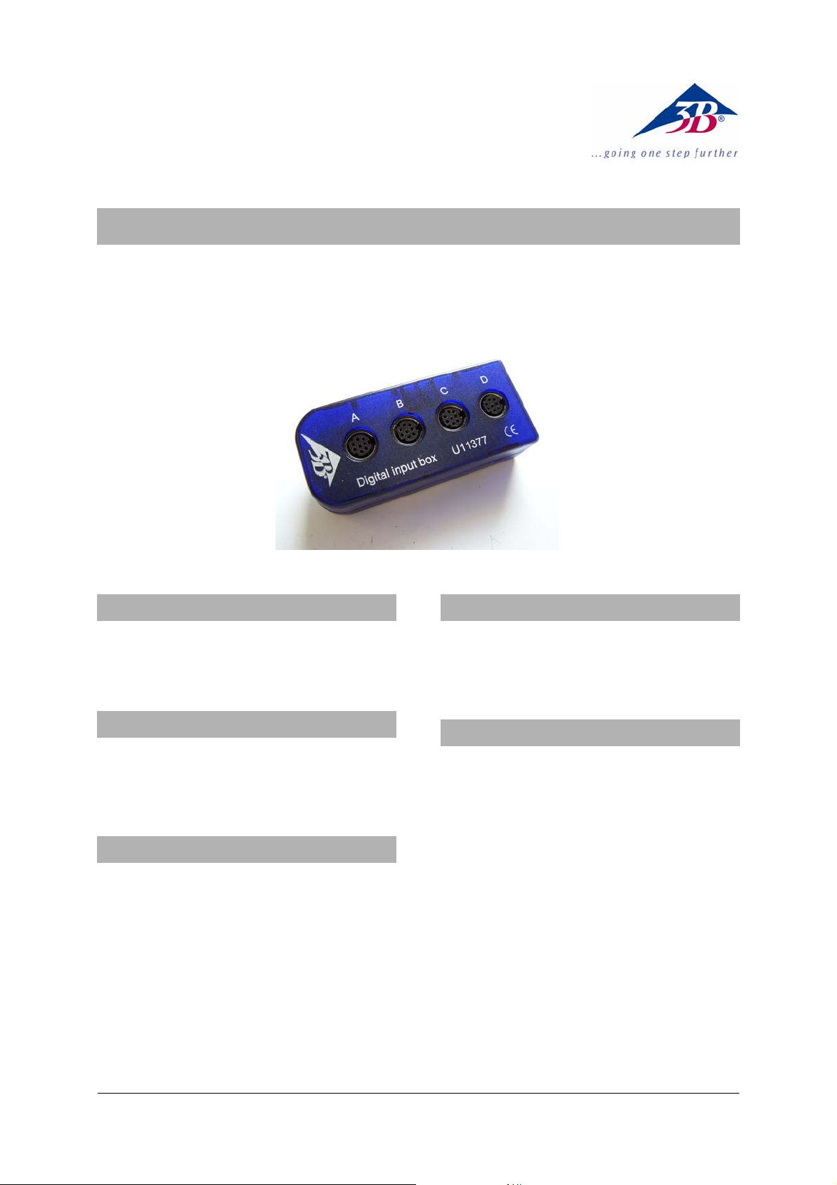
Digital Input Box U11377
Instruction sheet
09/08 Hh
1. Safety instructions
• The digital input box must be connected solely
to the “Digital Inputs” socket of a 3B NETlog
TM
unit.
2. Equipment supplied
1 Digital input box
1 8-pin miniDIN connecting cable, length 600 mm
1 Instruction sheet for U11377
3. Description
The digital input box is used for distributing digital
input channels A, B, C and D of a 3B NETlog
TM
(U11300) unit to four 8-pin miniDIN input sockets.
It allows for digital output signals from up to four
sensor boxes (e.g., photo gate U11365, laser
reflection sensor U8533380, and Geiger-Müller box
U11391) to be connected to the 3B NETlog
TM
unit at
the same time.
It is also possible to perform logical operations
using digital inputs A and B via the 3B NETlab
TM
(U11310) software
4. Technical data
Input signals: TTL level
Output signals: TTL level
Connections: 8-pin miniDIN sockets
5. Operation
• Place the digital input box near the
experiment. Example: an air track (e.g.,
U40400 or U40405).
• Position two photo gates (e.g., U11365)
alongside the air track and connect them via
their miniDIN cables to the input sockets A and
B of the digital input box.
• Connect the digital input box via miniDIN
cable to the 3B NETlog
• Configure the two digital inputs A and B to be
linked using 3B NETlab
TM
unit.
TM
(input mode for
“Digital inputs A+B”) and evaluate the results
from the experimental data.
1
Page 2
6. Applications
Measuring the position, velocity and acceleration of
moving bodies using multiple photo gates.
7. Sample experiment
Measuring the velocity of a body on an air track
Apparatus needed:
TM
1 3B NETlog
U11300
1 Digital input box U11377
2 Photo gates U11365
1 Air track, 1.6 m U40405
1 Set of 4 velocity flags U40426
1 Air flow generator (230 V, 50/60 Hz)
U15425-230
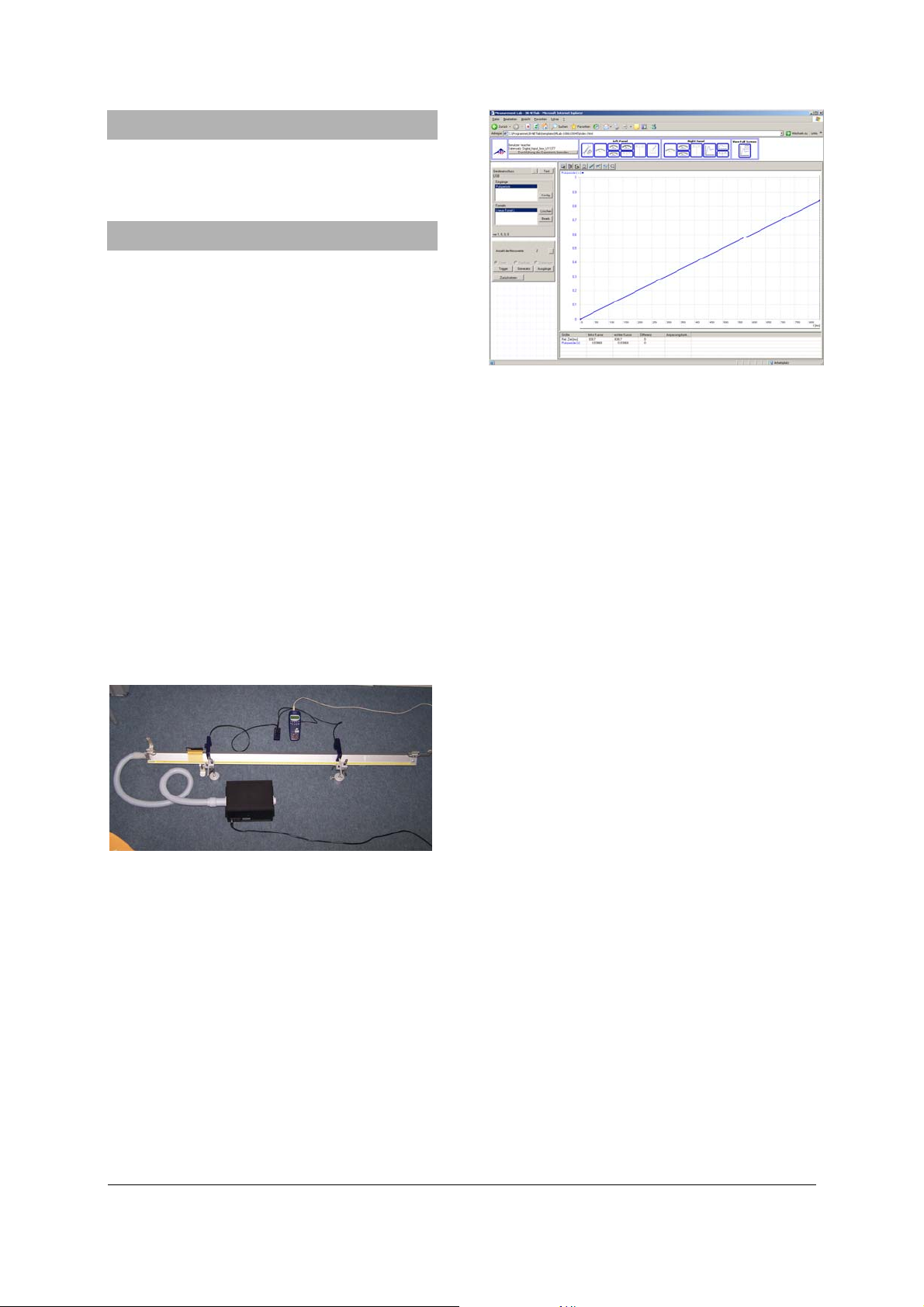
Fig. 2: Measurements of the time interval (number of
timer pulses) for the rider to travel between two points
on the air track
or
1 Air flow generator (115 V, 50/60 Hz)
U15425-115
2 Stand base, 1 kg U13265
2 Stand rods, 100 mm U15000
2 Universal clamps U13255
• Assemble stands by inserting stand rods into
two bases and attach the two photo gates to
them at the desired positions on the air track
(Fig. 1).
Fig. 1: Measuring the velocity of a glider over a given
distance on the air track
• On the 3B NETlog
mode, and in the software of the 3B NETlab
TM
, select the digital input
TM
select the experiment template for measuring
the velocity of a glider on the air track. The
software contains all the necessary instructions
for setting up the calculation.
• Carry out the experiment and evaluate the
result.
3B Scientific GmbH • Rudorffweg 8 • 21031 Hamburg • Germany • www.3bscientific.com
Subject to technical amendments
© Copyright 2008 3B Scientific GmbH
 Loading...