

Page 1

3B SCIENTIFIC® PHYSICS
Digitale Eingangsbox U11377
Bedienungsanleitung
09/08 Hh
1. Sicherheitshinweise
• Die Digitale Eingangsbox ausschließlich an der
Buchse „Digital Inputs“ des 3B NETlog
TM
an-
schließen.
2. Lieferumfang
1 Digitale Eingangsbox
1 miniDIN-Anschlusskabel 8-pin, 600 mm lang
1 Bedienungsanleitung für U11377
3. Beschreibung
Eingangsbox zur Auffächerung der digitalen Eingänge A, B, C und D des 3B NETlog
TM
(U11300) auf
vier miniDIN8-Buchsen.
Verwendbar für den gleichzeitigen Anschluss von
Sensorboxen mit digitalen Ausgangssignalen, z. B.
der Lichtschranke U11365, des Laser-Reflexsensors
U8533380 und der Geiger-Müller-Box U11391.
Logische Verknüpfungsmöglichkeit der digitalen
Eingänge A und B in der Software 3B NETlab
TM
(U11310).
4. Technische Daten
Eingangssignale: TTL-Pegel
Ausgangssignale: TTL-Pegel
Anschlüsse: 8pin-miniDIN-Buchsen
5. Bedienung
• Die Digitale Eingangsbox in der Nähe des Expe-
rimentes platzieren, z. B. an einer Luftkissenfahrbahn (z. B. U40400, U40405).
• Zwei Lichtschranken (z. B. U11365) an der
Fahrbahn aufstellen und mit den miniDINKabeln an den Eingangsbuchsen A und B der
Digitalen Eingangsbox anschließen.
• Die Digitale Eingangsbox mit dem miniDIN-
Kabel am 3B NETlog
• In 3B NETlab
TM
TM
anschließen.
in der Konfiguration des Eingangs die beiden digitalen Eingänge A und B
verknüpfen (Eingangsmodus "Digitaleingänge
A+B") und die gemessenen Daten auswerten.
1
Page 2

6. Anwendungen
Messung von Ort, Geschwindigkeit und Beschleunigung von bewegten Körpern mit mehreren Lichtschranken.
7. Versuchsbeispiel
Geschwindigkeitsmessung eines Körpers auf der
Luftkissenfahrbahn
Benötigte Geräte:
1 3B NETlog
TM
U11300
1 Digitale Eingangsbox U11377
2 Lichtschranken U11365
1 Luftkissenfahrbahn, 1,6 m U40405
1 Satz 4 Unterbrecherfahnen U40426
1 Luftstromerzeuger (230 V, 50/60 Hz)
U15425-230
oder
1 Luftstromerzeuger (115 V, 50/60 Hz)
U15425-115
2 Tonnenfüße, 1 kg U13265
2 Stativstangen, 100 mm lang U15000
2 Universalmuffen U13255
• Lichtschranken mit Hilfe der Tonnenfüße und
des Stativmaterials an den gewünschten Positionen der Luftkissenfahrbahn aufstellen (Fig. 1).
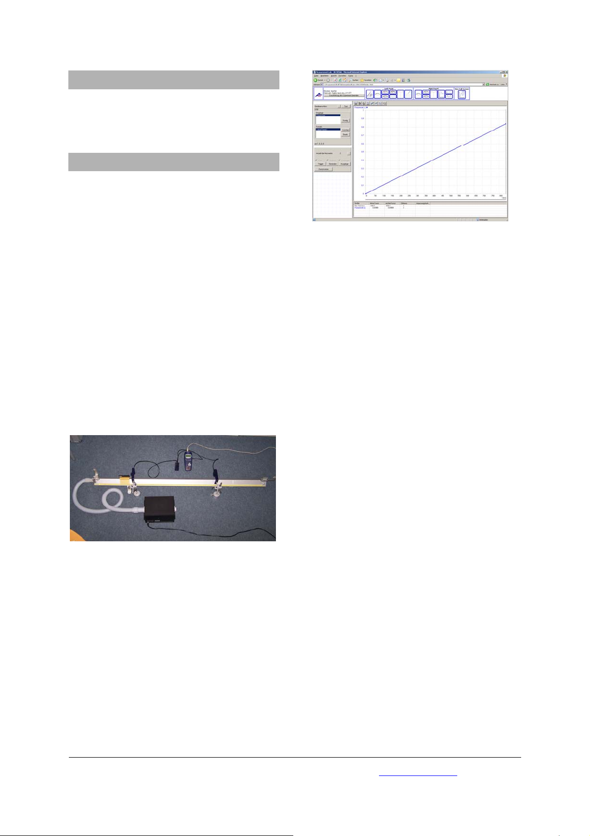
Fig. 2: Messung der Zeitspanne (Pulsperiode) zwischen
zwei Passagen des Gleiters auf der Luftkissenfahrbahn
Fig. 1: Messung der Geschwindigkeit eines Gleiters auf
der Luftkissenfahrbahn bei vorgegebener Distanz der
Lichtschranken
• Am 3B NETlog
und in der Software 3B NETlab
TM
die Digitaleingänge wählen
TM
das Experiment (Template) für die Messung der Geschwindigkeit eines Gleiters auf der Luftkissenbahn wählen; hier befinden sich alle erforderlichen Auswerteeinstellungen.
• Das Experiment durchführen und auswerten:
3B Scientific GmbH • Rudorffweg 8 • 21031 Hamburg • Deutschland • www.3bscientific.com
Technische Änderungen vorbehalten
© Copyright 2008 3B Scientific GmbH
Page 3

3B SCIENTIFIC® PHYSICS
Digital Input Box U11377
Instruction sheet
09/08 Hh
1. Safety instructions
• The digital input box must be connected solely
to the “Digital Inputs” socket of a 3B NETlog
TM
unit.
2. Equipment supplied
1 Digital input box
1 8-pin miniDIN connecting cable, length 600 mm
1 Instruction sheet for U11377
3. Description
The digital input box is used for distributing digital
input channels A, B, C and D of a 3B NETlog
TM
(U11300) unit to four 8-pin miniDIN input sockets.
It allows for digital output signals from up to four
sensor boxes (e.g., photo gate U11365, laser
reflection sensor U8533380, and Geiger-Müller box
U11391) to be connected to the 3B NETlog
TM
unit at
the same time.
It is also possible to perform logical operations
using digital inputs A and B via the 3B NETlab
TM
(U11310) software
4. Technical data
Input signals: TTL level
Output signals: TTL level
Connections: 8-pin miniDIN sockets
5. Operation
• Place the digital input box near the
experiment. Example: an air track (e.g.,
U40400 or U40405).
• Position two photo gates (e.g., U11365)
alongside the air track and connect them via
their miniDIN cables to the input sockets A and
B of the digital input box.
• Connect the digital input box via miniDIN
cable to the 3B NETlog
• Configure the two digital inputs A and B to be
linked using 3B NETlab
TM
unit.
TM
(input mode for
“Digital inputs A+B”) and evaluate the results
from the experimental data.
1
Page 4

6. Applications
Measuring the position, velocity and acceleration of
moving bodies using multiple photo gates.
7. Sample experiment
Measuring the velocity of a body on an air track
Apparatus needed:
TM
1 3B NETlog
U11300
1 Digital input box U11377
2 Photo gates U11365
1 Air track, 1.6 m U40405
1 Set of 4 velocity flags U40426
1 Air flow generator (230 V, 50/60 Hz)
U15425-230
Fig. 2: Measurements of the time interval (number of
timer pulses) for the rider to travel between two points
on the air track
or
1 Air flow generator (115 V, 50/60 Hz)
U15425-115
2 Stand base, 1 kg U13265
2 Stand rods, 100 mm U15000
2 Universal clamps U13255
• Assemble stands by inserting stand rods into
two bases and attach the two photo gates to
them at the desired positions on the air track
(Fig. 1).
Fig. 1: Measuring the velocity of a glider over a given
distance on the air track
• On the 3B NETlog
mode, and in the software of the 3B NETlab
TM
, select the digital input
TM
select the experiment template for measuring
the velocity of a glider on the air track. The
software contains all the necessary instructions
for setting up the calculation.
• Carry out the experiment and evaluate the
result.
3B Scientific GmbH • Rudorffweg 8 • 21031 Hamburg • Germany • www.3bscientific.com
Subject to technical amendments
© Copyright 2008 3B Scientific GmbH
Page 5

3B SCIENTIFIC® PHYSICS
Boîte d'entrée numérique U11377
Instructions d’utilisation
09/08 Hh
1. Consignes de sécurité
• Raccordez la boîte d'entrée numérique exclusi-
vement à la douille « Digital Inputs » du 3B
TM
NETlog
.
2. Étendue de la livraison
1 boîte d'entrée numérique
1 câble de raccordement mini-DIN, 8 broches,
d'une longueur de 60 cm
1 Instructions d’utilisation pour U11377
3. Description
Boîte d'entrée permettant la segmentation des
entrées numériques A, B, C et D du 3B NETlog
TM
(U11300) sur quatre douilles mini-DIN 8 broches.
Utilisable pour le raccordement simultané de boî-
tiers avec des signaux de sortie numériques, par
exemple la barrière photoélectrique (U11365), le
capteur réflectif à laser (U8533380) et la boîte Geiger-Müller (U11391).
Possibilité d'une liaison logique des entrées numériques A et B au logiciel 3B NETlab
TM
(U11310).
4. Caractéristiques techniques
Signaux d'entrée : Niveau TTL
Signaux de sortie : Niveau TTL
Raccordements : Douilles mini-
DIN, 8 broches
5. Manipulation
• Placez la boîte d'entrée numérique à proximité
de l'essai expérimental, par exemple sur une
piste à coussin d’air (U40400, U40405, etc.).
• Placez deux barrières photoélectriques (par
exemple U11365) sur la piste à coussin d’air ;
puis raccordez-les avec les câbles mini-DIN aux
douilles d'entrée A et B de la boîte d'entrée
numérique.
• Raccordez la boîte d'entrée numérique au
câble mini-DIN du 3B NETlog
• Sur 3B NETlab
TM
, reliez les deux entrées numé-
TM
.
riques A et B (mode d'entrée : « Entrées numériques A+B ») dans la configuration de l'entrée,
puis évaluez les données mesurées.
1
Page 6

6. Applications
Mesure de la position, de la vitesse et de l'accélération de corps en mouvement avec plusieurs barrières photoélectriques.
7. Exemple d’expérience
Mesure de la vitesse d'un corps sur la piste à
coussin d’air
Dispositifs nécessaires :
1 3B NETlog
1 boîte d'entrée numérique U11377
2 barrières photoélectriques U11365
1 piste à coussin d’air, 1,6 m U40405
TM
U11300
Fig. 2 : Mesure de l'intervalle de temps (période d'impulsion) entre deux passages du patin sur la piste à coussin
d’air
1 jeu de 4 drapeaux de coupure U40426
1 générateur de courant d'air (230 volts, 50 - 60 Hz)
U15425-230
ou
1 générateur de courant d'air (115 volts, 50 - 60 Hz)
U15425-115
2 pieds coniques à tige, 1 kg U13265
2 tiges de statif, longueur 100 mm U15000
2 noix universelles U13255
• À l'aide des pieds coniques à tige et des tiges
de statif, placez les barrières photoélectriques
dans les positions désirées sur la piste à coussin d’air (Fig. 1).
Fig. 1 : Mesure de la vitesse d'un patin sur la piste à
coussin d’air pour une distance prédéfinie des barrières
photoélectriques
• Sélectionnez les entrées numériques sur
3B NETlog
3B NETlab
TM
, puis sélectionnez dans le logiciel
TM
l'essai expérimental (modèle) pour
la mesure de la vitesse d'un patin sur la piste à
coussin d’air ; tous les paramétrages d'analyse
nécessaires s'y trouvent.
• Réalisez l'essai expérimental, puis analysez-le :
3B Scientific GmbH • Rudorffweg 8 • 21031 Hamburg • Allemagne • www.3bscientific.com
Sous réserve de modifications techniques
© Copyright 2008 3B Scientific GmbH
Page 7

3B SCIENTIFIC® PHYSICS
Box di ingresso digitale U11377
Istruzioni per l'uso
09/08 Hh
1. Norme di sicurezza
• Collegare il box di ingresso digitale
esclusivamente al jack „Digital Inputs“ di 3B
TM
NETlog
.
2. Fornitura
1 Box di ingresso digitale
1 Cavo di collegamento miniDIN da 8 pin,
lungh. 600 mm
1 Manuale d'istruzioni per U11377
3. Descrizione
Box di ingresso per il fan out degli ingressi digitali
A, B, C e D di 3B NETlog
TM
(U11300) su quattro prese
mini DIN8.
Utilizzabile per il collegamento contemporaneo di
box del sensore con segnali di uscita digitali, ad
esempio della fotocellula U11365, del sensore di
riflessione laser U8533380 e della scatola di GeigerMüller U11391.
Possibilità di operazioni logiche degli ingressi
digitali A e B nel software 3B NETlab
TM
(U11310).
4. Dati tecnici
Segnali di ingresso: Livello TTL
Segnali di uscita: Livello TTL
Collegamenti: Prese mini DIN a 8 pin
5. Utilizzo
• Collocare il box di ingresso digitale in
prossimità dell'esperimento, ad esempio su
una rotaia a cuscino d'aria (ad esempio
U40400, U40405).
• Disporre due fotocellule (ad esempio U11365)
sulla rotaia e collegarle con il cavo mini DIN ai
jack di ingresso A e B del box di ingresso
digitale.
• Collegare il box di ingresso digitale con il cavo
mini DIN a 3B NETlog
• In 3B NETlab
TM
TM
.
correlare i due ingressi digitali
A e B nella configurazione dell'ingresso
(modalità ingresso "Ingressi digitali A+B) e
analizzare i dati misurati.
1
Page 8

6. Applicazioni
Misurazione di posizione, velocità e accelerazione
di corpi in movimento con più fotocellule.
7. Esperimento di esempio
Misurazione della velocità di un corpo sulla
rotaia a cuscino d'aria
Apparecchi necessari:
1 3B NETlog
TM
U11300
1 Box di ingresso digitale U11377
2 Fotocellule U11365
1 Rotaia a cuscino d'aria, 1,6 m U40405
1 Set di 4 bandierine U40426
1 Generatore di corrente d'aria (230 V, 50/60 Hz)
U15425-230
o
1 Generatore di corrente d'aria (115 V, 50/60 Hz)
U15425-115
2 Piedi a barilotto, 1 kg U13265
2 Aste di supporto, lungh. 100 mm U15000
2 Manicotti universali U13255
• Disporre le fotocellule nelle posizioni
desiderate della rotaia a cuscino d'aria
mediante i piedi a barilotto del materiale di
supporto (fig. 1).
Fig. 2: Misurazione dell'intervallo di tempo (periodo
impulso) tra due passaggi del carrello sulla rotaia a
cuscino d'aria
Fig. 1: Misurazione della velocità di un carrello sulla
rotaia a cuscino d'aria in caso di distanza predefinita
delle fotocellule.
• Selezionare su 3B NETlog
attivare nel software 3B NETlab
TM
gli ingressi digitali e
TM
l’esperimento
(Template) per la misurazione della velocità di
un carrello sulla rotaia a cuscino d'aria; qui
sono presenti tutte le impostazioni necessarie
per la valutazione.
• Eseguire l’esperimento e procedere alla
valutazione:
3B Scientific GmbH • Rudorffweg 8 • 21031 Amburgo • Germania • www.3bscientific.com
Con riserva di modifiche tecniche
© Copyright 2008 3B Scientific GmbH
Page 9

3B SCIENTIFIC® PHYSICS
Caja de entradas digitales U11377
Instrucciones de uso
09/08 Hh
1. Advertencias de seguridad
• La caja de entradas digitales se conecta
exclusivamente en el casquillo “Digital imputs“
del 3B NETlog
TM
.
2. Volumen de entrega
1 Caja de entradas digitales
1 Cable de conexión miniDIN de 8 pines, 600 mm
de largo
1 Instrucciones de uso para U11377
3. Descripción
Caja de entrada para la ramificación de las
entradas digitales A, B, C y D del 3B NETlog
TM
(U11300) sobre cuatro casquillos miniDIN8.
Utilizable para conexión simutánea de cajas de
sensores con señales de salida digitales, p. ej. la
puerta fotoeléctrica U11365, el sensosor de
reflexión de Láser U8533380, la caja del GeigerMüller U11391 U11365.
Posibilidad de la combinación lógica de las
entradas A y B en el Software del 3B NETlab
TM
(U11310).
4.Datos técnicos
Señales de entrada: Nivel TTL
Señales de salida: Nivel TTL
Puntos de conexión: Casquillos miniDIN
de 8 pi pines
5.Manejo
• La caja de entradas digitales se coloca cerca del
experimento p. ej. de un carril de cojín
neumático (ya sea. U40400, U40405).
• Se colocan dos puertas fotoeléctricas (p. ej.
U11365) al lado del carril y, con un cable
miniDIN, se conectan con los casquillos A y B
de la caja de entradas digitales.
• La caja de entradas digitales se conecta con el
3B NETlog
TM
(U11300), utilizando un cable
miniDIN.
• En el 3B NETlab
TM
, en la configuración de la
entrada. se conbinan las entradas digitales A y
B, (modo de entrada: "Digitaleingänge A+B") y
se evalúan los datos medidos.
1
Page 10
6. Aplicaciones
Medición de la posición, la velocidad y la
aceleración de cuerpos en movimiento utilizando
varias puestas fotoeléctricas.
7. Ejemplo de experimentación
Medición de la velocidad de un cuerpo en un
carril de cojín neumático
Aparatos requeridos:
1 3B NETlog
TM
U11300
1 Caja de entradas digitales U11377
2 Puertas fotoeléctricas U11365
1Carril neumático, 1,6 m U40405
1 Juego de 4 banderolas U40426
1 Soplador (230 V, 50/60 Hz) U15425-230
alternativamente
1 Soplador (115 V, 50/60 Hz) U15425-115
2 Pies cónicos, 1 kg U13265
2 Varillas soporte, l = 100 mm U15000
2 Mangos universales U13255
• Con los pies soporte y el material de montaje
se colocan las puertas fotoeléctricas en las
posiciones deseadas en la cercanía del carril
neumático (Fig. 1).
Fig. 2: Medición del intervalo de tiempo (período del
pulso) entre dos pasos del deslizador en el cojín
neumático.
Fig. 1: Medición de la velocidad de un deslizador en el
carril neumático con una distancia prefijada entre las
puertas fotoeléctricas
• En el 3B NETlog
digitales y en el Software 3B NETlab
TM
se seleccionan las entradas
TM
se elige
el experimento (templete) para la medición de
la velocidad de un deslizador en el carril de
cojín neumáticodie; alli se encuentran los
ajustes necesarios para la evaluación.
• Se realiza y se evalúa el experimento:
3B Scientific GmbH • Rudorffweg 8 • 21031 Hamburgo ▪ Alemania • www.3bscientific.com
Nos reservamos el derecho a cambios técnicos
© Copyright 2008 3B Scientific GmbH
Page 11

3B SCIENTIFIC® FÍSICA
Caixa Digital de Entrada U11377
Instruções de operação
09/08 Hh
1. Indicações de Segurança
• Conectar a Caixa Digital de Entrada
exclusivamente na tomada “Digital Inputs“ do
3B NETlog
TM
.
2. Fornecimento
1 Caixa Digital de Entrada
1 Cabo ‘miniDIN’ de conexão 8-PT, 600 mm
de comprimento.
1 Instrução de operação para U11377
3. Descrição
Uma Caixa Digital de Entrada com ordem
incremental das entradas A, B, C e D do 3B NETlog
TM
(U11300) sobre quatro tomadas miniDIN8.
Para ser usado para a conexão simultânea de
caixas de sensores com sinais digitais de saída, por
exemplo, da barreira de luz U11365, do sensor de
reflexo Laser U8533380 e da caixa Geiger-Müller
U11391.
Possibilidade de enlace lógico das entradas digitais
A e B no Software do 3B NETlab
TM
(U11310).
4. Dados técnicos
Sinais de entrada: TTL-Nível
Sinais de saída: TTL-Nível
Ligações: Tomadas
8 pinos-miniDIN
5. Operação
• Colocar a Caixa Digital de Entrada nas
proximidades da experiência, por exemplo, um
trilho de colchão de ar (por exemplo, U40400,
U40405).
• Montar duas barreiras de luz (por exemplo,
U11365) no trilho e conectar com os cabos
miniDIN nas tomadas de entrada A e B da
Caixa Digital de Entrada.
• Conectar a Caixa de Entrada Digital com o cabo
miniDINl no 3B NETlog
• No 3B NETlab
TM
TM
.
, na configuração de entrada,
enlaçar as duas entradas digitais A e B (Modo
de entrada "Digitaleingänge A+B") e analisar
os dados medidos.
1
Page 12

6. Utilizações
Medição de lugar, velocidade e aceleração de
corpos movimentados com várias barreiras de luz.
7. Exemplo de experiência
Medição de velocidade de um corpo sobre o
trilho de colchão de ar
Aparelhos necessários:
1 3B NETlog
TM
U11300
1 Caixa Digital de Entrada U11377
2 Barreiras de luz U11365
1 Trilho de colchão de ar 1,6 m U40405
1 Conjunto de 4 bandeiras de interrupção U40426
1 Gerador de corrente de ar (230 V, 50/60 Hz)
U15425-230
ou
1 Gerador de corrente de ar (115 V, 50/60 Hz)
U15425-115
2 Bases em tonel, 1 kg U13265
2 Varas de apoio, 100 mm de comprimento
U15000
2 Mangas universais U13255
• Montar as barreiras de luz com ajuda dos pesos
de barril e o material de suporte nas posições
desejadas no trilho de colchão de ar (Fig. 1).
Fig. 2: Medição do intervalo de tempo (período de pulso)
entre duas passagens do deslizador sobre o trilho de
colchão de ar
Fig. 1: Medição da velocidade de um deslizador sobre o
trilho de colchão de ar numa distância de Barreiras de
luz preestabelecida
• Selecionar no 3B NETlog
no Software 3B NETlab
TM
as entradas digitais e
TM
selecionar a
experiência (predefinida) para a medição de
velocidade de um deslizador sobre o trilho de
colchão de ar; aqui se encontram todas as
colocações de análise necessárias.
• Executar a experiência e analisar:
3B Scientific GmbH • Rudorffweg 8 • 21031 Hamburgo • Alemanha • www.3bscientific.com
Sob reserva de alterações técnicas
© Copyright 2008 3B Scientific GmbH
 Loading...