

Page 1
3B SCIENTIFIC® PHYSICS
Digital Binocular Microscope with Built-in Camera
1013153
Instruction Manual
08/13 ALF
1. Safety notes
• For power supply use only electrical sockets
with ground contact.
Caution! The Stirling engine becomes hot during
use. Risk of burns!
• Do not touch the lamp during or immediately
after use.
2. Description, technical data
The digital binocular microscope with built-in
camera allows two-dimensional viewing of objects (thin sections of plant or animal specimen)
in 40x to 1000x magnification. It also allows
photographic or video-recording documentation
of images.
As well as real-time video playback, single images, sequences and video recording, the ScopeImage software provides a wide range of
functions for the presentation, processing and
evaluation of images.
The installation CD contains a detailed description of the software in English, and additional
advice and assistance is available in the help
files of the software.
Stand: All-metal stand, arm firmly connected
with base, pinion knobs attached on both sides
of the stand for coarse and fine focusing
Tube: Binocular inclined 45°, head rotation 360°
Eyepiece: Pair of wide field eyepieces WF 10x
18 mm
Objectives: Revolving nosepiece with 4 achro-
matic objectives 4x / 0.10, 10x / 0.25, 40x / 0.65,
100x / 1.25 (oil)
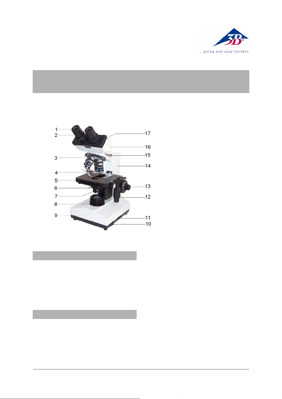
1 Eyepiece
2 Tube
3 Revolver with objectives
4 Object guide
5 Object stage
6 Condenser with iris dia-
phragm and filter holder
7 Condenser control
8 Lamp housing
9 Base
10 Mains switch
11 Illumination control
12 Coaxial movement control
for the specimen stage
13 Coarse and fine movement
controls with holding brake
14 Stand
15 Head lock screw
16 Camera
17 USB connection
1
Page 2

Magnification: 40x, 100x, 400x, 1000x
Object stage: x-y mechanical stage, 140 mm x
140 mm, with object guide, adjustment range 75
mm x 50 mm
Illumination: Adjustable 6 V, 20 W halogen lamp
integrated in base. Universal 100 V to 240 V,
50/60 Hz power supply
Condenser: Abbe condenser N.A.1.25 with iris
diaphragm , filter holder and filter, focussed via
rack and pinion drive
Camera sensor: 1/3” CMOS, 1.3 Mpixel, colour
prints
Power supply: via USB 2.0
System requirements: WIN2000, WINXP,
Vista, WIN7 and WIN8
Dimensions: 220 x 180 x 390 mm³ approx.
Weight: 8.5 kg approx.
3. Unpacking and assembly
The microscope is packed in a molded styrofoam container.
• Take the container out of the carton remove
the tape and carefully lift the top half off the
container. Be careful not to let the optical
items (objectives and eyepieces) drop down.
• To avoid condensation on the optical com-
ponents, leave the microscope in the original
packing to allow it to adjust to room temperature.
• Using both hands (one around the pillar and
one around the base), lift the microscope
from the container and put it on a stable
desk.
• The objectives will be found within individual
protective vials. Install the objectives into the
microscope nosepiece from the lowest
magnification to the highest, in a clockwise
direction from the rear.
• Put the head onto the top of the stand and
tighten the head-lock-screw. Insert the eyepieces into the tube.
4. Operation
4.1 General information
• Set the microscope on a level table.
• Place the object to be observed in the center
of the object plate. Use the clips to fasten it
into place. Make certain that the specimen is
centered over the opening in the stage.
• Connect the mains cable to the net and turn
on the switch to get the object illuminated.
• Adjust the interpupillary distance so that one
circle of light can be seen.
• Make the necessary eyepiece dioptre ad-
justments to suit your eyes.
• To obtain a high contrast, adjust the back-
ground illumination by means of the iris diaphragm and the variable illumination control.
• Rotate the nosepiece until the objective with
the lowest magnification is pointed at the
specimen. There is a definite “click” when
each objective is lined up properly.
NOTE: It is best to begin with the lowest power
objective. This is important to reveal general
structural details with the largest field of view
first. Than you may increase the magnification
as needed to reveal small details. When 100x
(oil) objective is chosen, objective oil must be
dripped onto the slide.
To determine the magnification at which you are
viewing a specimen, multiply the power of the
eyepiece by the power of the objective.
• Adjust the coarse-focusing-knob which
moves the stage up until the specimen is focused. Be careful that the objective does not
make contact with the slide at any time. This
may cause damage to the objective and/or
crack your slide.
• Adjust the fine-focusing-knob to get the im-
age more sharp and more clear.
• Colour filters may be inserted into the filter
holder for definition of specimen parts.
Swing the filter holder out and insert colour
filters.
• Use the knobs of the mechanical stage to
move the slide side-, back- and forwards.
The vernier provides acc urate loc ation of the
specimen area.
• Always turn off the light immediately after
use.
• Be careful not to spill any liquids on the mi-
croscope.
• Do not mishandle or impose unnecessary
force on the microscope.
• Do not wipe the optics with your hands.
• Do not attempt to service the microscope
yourself.
4.2 Installation of the software
• Insert the installation CD into the computer’s
CD drive.
• Follow the installation instructions (see also
the description of the software on the installation CD).
4.3 Displaying images on the computer
• Connect the microscope to the computer
using the USB cable.
• Start up the software.
2
Page 3

After clicking on the camera icon in the tool-
•
bar, the image of the specimen will appear
on the computer screen.
• If necessary, re-adjust the brightness and
contrast using the iris diaphragm and the variable illumination control.
• Adjust the sharpness of the image by means
of the focusing knobs of the microscope.
• If necessary, adjust the settings of the ca-
mera in the video window according to the
particular requirements.
• For further work using the software, see the
instructions for the software that are on the
installation CD and the help files in the software.
4.4 Changing the lamp and fuse
4.4.1 Changing the lamp
• Turn off the power switch, unplug the mains
plug and let the lamp cool down to avoid being burnt.
• For safety reasons, remove the eyepiece.
• To change the lamp lay the microscope on
its back to reach the lid on the bottom side.
• Loosen screw A and open the cover.
• To remove the halogen lamp, use a cloth or
similar material. Do not touch the bulb with
the bare hand.
• Lift out the halogen lamp and replace it with
a new one.
• Close the cover and secure it with the
screw.
D
C
B
4.4.2 Changing the fuse
• Turn off the power switch and unplug the
mains plug.
• Lay the microscope on its side.
• Unscrew the fuse holder D.
• Replace the fuse and reinsert the holder in
its socket.
4.5 Using the polarisation equipment
• Screw the mirror onto the rim aperture of the
light source.
5. Storage, cleaning and disposal
• Keep the microscope in a clean, dry and
dust free place.
• When not in use always cover the micro-
scope with the dust cover.
• Do not expose it to temperatures below 0°C
and above 40°C and a max. relative humidity of over 85%.
• Always unplug the mains plug before clean-
ing or maintenance.
• Do not clean the unit with volatile solvents or
abrasive cleaners.
• Do not disassemble objective or eyepieces
to attempt to clean them.
• Use a soft linen cloth and some ethanol to
clean the microscope.
• Use a soft lens tissue to clean the optics.
• The packaging should
be disposed of at local
recycling points.
• Should you need to
dispose of the equipment itself, never throw
it away in normal domestic waste. Local
regulations for the disposal of electrical
equipment will apply.
A
Fig. 1 Lamp socket cover: A - knurled screw, B - ventilation slot, C - securing screws of lamp-holder, D fuse holder
3B Scientific GmbH • Rudorffweg 8 • 21031 Hamburg • Germany • www.3bscientific.com
Subject to technical amendments
© Copyright 2013 3B Scientific GmbH
Page 4

 Loading...