


 Loading...
2N® Lift8
Communicator for lifts
User manual
Firmware |
1.6.0 |
|
Version |
1.6.0 |
www.2n.cz |
The 2N TELEKOMUNIKACE a.s. is a Czech manufacturer and supplier of telecommunications equipment.
The product family developed by 2N TELEKOMUNIKACE a.s. includes GSM gateways, private branch exchanges (PBX), and door and lift communicators. 2N TELEKOMUNIKACE a.s. has been ranked among the Czech top companies for years and represented a symbol of stability and prosperity on the telecommunications market for almost two decades. At present, we export our products into over 120 countries worldwide and have exclusive distributors on all continents.
2N® is a registered trademark of 2N TELEKOMUNIKACE a.s. Any product and/or other names mentioned herein are registered trademarks and/or trademarks or brands protected by law.
2N TELEKOMUNIKACE a.s. administers the FAQ database to help you quickly find information and to answer your questions about 2N products and services. On www.faq.2n.cz you can find information regarding products adjustment and instructions for optimum use and procedures „What to do if...“.
2N TELEKOMUNIKACE a.s. hereby declares that the 2N® Lift8 product complies with all basic requirements and other relevant provisions of the 1999/5/EC directive. For the full wording of the Declaration of Conformity see the CD-ROM (if enclosed) or our website at www.2n.cz.
The 2N TELEKOMUNIKACE a.s. is the holder of the ISO 9001:2009 certificate. All development, production and distribution processes of the company are managed by this standard and guarantee a high quality, technical level and professional aspect of all our products.
Content
1. Product Introduction . . . . . . . . . . . . . . . . . . . . . . . . . . . . . . . . 5
1.1 |
Product Description . . . . . . . . . . . . . . . . . . . . . . . . . . . . . . . . . . . . . . . . . . . . . . |
6 |
1.2 |
Components and Associated Products . . . . . . . . . . . . . . . . . . . . . . . . . . . . . . . |
8 |
1.3 |
Upgrade . . . . . . . . . . . . . . . . . . . . . . . . . . . . . . . . . . . . . . . . . . . . . . . . . . . . . . . |
21 |
1.4 |
Terms and Symbols Used . . . . . . . . . . . . . . . . . . . . . . . . . . . . . . . . . . . . . . . . . |
22 |
2. Description and Installation . . . . . . . . . . . . . . . . . . . . . . . . . . |
23 |
|
2.1 |
PSTN/GSM/UMTS/VoIP Central Unit . . . . . . . . . . . . . . . . . . . . . . . . . . . . . . . . . |
24 |
2.2 |
Splitter . . . . . . . . . . . . . . . . . . . . . . . . . . . . . . . . . . . . . . . . . . . . . . . . . . . . . . . . |
37 |
2.3 |
Audio Unit – Cabin Universal . . . . . . . . . . . . . . . . . . . . . . . . . . . . . . . . . . . . . . . |
43 |
2.4 |
Audio Unit – Machine Room . . . . . . . . . . . . . . . . . . . . . . . . . . . . . . . . . . . . . . . . |
55 |
2.5 |
Audio Unit – Shaft . . . . . . . . . . . . . . . . . . . . . . . . . . . . . . . . . . . . . . . . . . . . . . . . |
60 |
2.6 |
Audio Unit – Compact . . . . . . . . . . . . . . . . . . . . . . . . . . . . . . . . . . . . . . . . . . . . . |
64 |
2.7 PSTN Module . . . . . . . . . . . . . . . . . . . . . . . . . . . . . . . . . . . . . . . . . . . . . . . . . . . |
75 |
|
2.8 GSM/UMTS Module . . . . . . . . . . . . . . . . . . . . . . . . . . . . . . . . . . . . . . . . . . . . . . |
77 |
|
2.9 |
VoIP Module . . . . . . . . . . . . . . . . . . . . . . . . . . . . . . . . . . . . . . . . . . . . . . . . . . . . |
79 |
2.10 Audio Unit – Fireman . . . . . . . . . . . . . . . . . . . . . . . . . . . . . . . . . . . . . . . . . . . . |
81 |
|
2.11 I/O Module . . . . . . . . . . . . . . . . . . . . . . . . . . . . . . . . . . . . . . . . . . . . . . . . . . . . |
103 |
|
3. System Configuration . . . . . . . . . . . . . . . . . . . . . . . . . . . . . . . |
109 |
|
3.1 |
2N® Lift8 Programming . . . . . . . . . . . . . . . . . . . . . . . . . . . . . . . . . . . . . . . . . . . |
110 |
3.2 |
Table of Parameters (FW 1.6.0) . . . . . . . . . . . . . . . . . . . . . . . . . . . . . . . . . . . . . |
113 |
4. Function and Use . . . . . . . . . . . . . . . . . . . . . . . . . . . . . . . . . . |
126 |
|
4.1 |
User Instructions . . . . . . . . . . . . . . . . . . . . . . . . . . . . . . . . . . . . . . . . . . . . . . . . . |
127 |
4.2 |
Control Centre Instructions . . . . . . . . . . . . . . . . . . . . . . . . . . . . . . . . . . . . . . . . . |
129 |
4.3 |
Function Description (for Advanced Users) . . . . . . . . . . . . . . . . . . . . . . . . . . . . |
131 |
4.4 |
Call Confirmation Types . . . . . . . . . . . . . . . . . . . . . . . . . . . . . . . . . . . . . . . . . . . |
135 |
4.5 |
Lift Blocking Function . . . . . . . . . . . . . . . . . . . . . . . . . . . . . . . . . . . . . . . . . . . . . |
138 |
4.6 |
Four-Lift Version . . . . . . . . . . . . . . . . . . . . . . . . . . . . . . . . . . . . . . . . . . . . . . . . . |
139 |
4.7 |
Intercom Function . . . . . . . . . . . . . . . . . . . . . . . . . . . . . . . . . . . . . . . . . . . . . . . . |
141 |
5. Service Tool . . . . . . . . . . . . . . . . . . . . . . . . . . . . . . . . . . . . . . . 144
5.1 |
Installation and Login . . . . . . . . . . . . . . . . . . . . . . . . . . . . . . . . . . . . . . . . . . . . . |
145 |
5.2 |
Introduction to Application . . . . . . . . . . . . . . . . . . . . . . . . . . . . . . . . . . . . . . . . . |
148 |
5.3 |
Use . . . . . . . . . . . . . . . . . . . . . . . . . . . . . . . . . . . . . . . . . . . . . . . . . . . . . . . . . . . |
155 |
6. Server . . . . . . . . . . . . . . . . . . . . . . . . . . . . . . . . . . . . . . . . . . . . 166
6.1 Installation and Licensing . . . . . . . . . . . . . . . . . . . . . . . . . . . . . . . . . . . . . . . . . . 167
6.2 Use . . . . . . . . . . . . . . . . . . . . . . . . . . . . . . . . . . . . . . . . . . . . . . . . . . . . . . . . . . . 170
7. Control Panel . . . . . . . . . . . . . . . . . . . . . . . . . . . . . . . . . . . . . . 174
7.1 |
Installation and Login . . . . . . . . . . . . . . . . . . . . . . . . . . . . . . . . . . . . . . . . . . . . . |
175 |
7.2 |
Introduction to Application . . . . . . . . . . . . . . . . . . . . . . . . . . . . . . . . . . . . . . . . . |
178 |
7.3 |
Use . . . . . . . . . . . . . . . . . . . . . . . . . . . . . . . . . . . . . . . . . . . . . . . . . . . . . . . . . . . |
183 |
8. Communicator . . . . . . . . . . . . . . . . . . . . . . . . . . . . . . . . . . . . . |
216 |
|
8.1 |
Installation and Login . . . . . . . . . . . . . . . . . . . . . . . . . . . . . . . . . . . . . . . . . . . . . |
217 |
8.2 |
Introduction to Application . . . . . . . . . . . . . . . . . . . . . . . . . . . . . . . . . . . . . . . . . |
220 |
8.3 |
Use . . . . . . . . . . . . . . . . . . . . . . . . . . . . . . . . . . . . . . . . . . . . . . . . . . . . . . . . . . . |
224 |
9. Maintenance . . . . . . . . . . . . . . . . . . . . . . . . . . . . . . . . . . . . . . |
234 |
|
9.1 |
Operation Interruption and Battery Replacement . . . . . . . . . . . . . . . . . . . . . . . . |
235 |
9.2 |
Firmware Upgrade . . . . . . . . . . . . . . . . . . . . . . . . . . . . . . . . . . . . . . . . . . . . . . . |
237 |
10. Technical Parameters . . . . . . . . . . . . . . . . . . . . . . . . . . . . . . 238
11. Supplementary Information . . . . . . . . . . . . . . . . . . . . . . . . . 241
11.1 |
Troubleshooting . . . . . . . . . . . . . . . . . . . . . . . . . . . . . . . . . . . . . . . . . . . . . . . . |
242 |
11.2 |
List of Abbreviations . . . . . . . . . . . . . . . . . . . . . . . . . . . . . . . . . . . . . . . . . . . . . |
243 |
11.3 |
Regulations . . . . . . . . . . . . . . . . . . . . . . . . . . . . . . . . . . . . . . . . . . . . . . . . . . . . |
244 |
11.4 |
General Instructions and Cautions . . . . . . . . . . . . . . . . . . . . . . . . . . . . . . . . . . |
245 |

1. Product Introduction
In this section, we introduce the 2N® Lift8 product, outline its application options and highlight the advantages following from its use.
Here is what you can find in this section:
 1.1 Product Description
 1.2 Components and Associated Products
 1.3 Upgrade
 1.4 Terms and Symbols Used
2N® TELEKOMUNIKACE a.s., www.2n.cz |
5 |

1.1 Product Description
Basic Features
 Up to 8-lift connectivity
 Lift cabin, shaft and machine room voice audio units
 Optimum acoustic properties
 Rechargeable built-in backup battery
 Easy control and configuration – voice response system
 Check Call function
 Lift blocking during connection failure
 Internal communication – Triphony
 Telephone/PC-based configuration (via USB or Internet)
 USB interface
 User message recording option
 Local control centre (Intercom)
 Fireman function
Basic Description
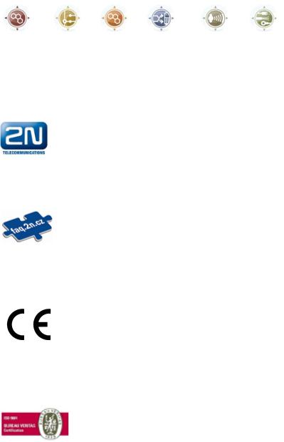
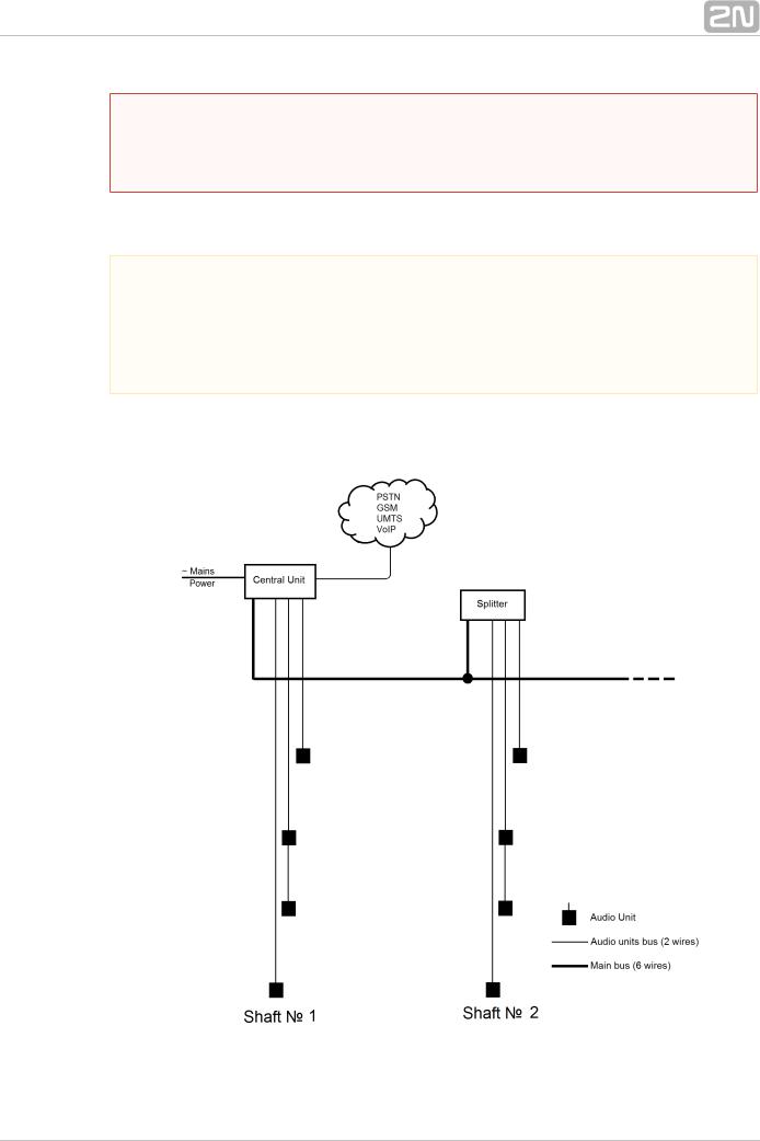
2N® Lift8 (L8) is a communication system with a function similar to an intercom. The system voice audio units are linked to a common bus (pair of wires), connected to a splitter. The splitter is always connected to a central unit (CU), which controls the system operation and provides connection with the control centre. It is possible to connect up to 40 audio units to the bus. The CU contains an internal splitter.
Each splitter is uniquely identified: by lift number 1 to 8. The audio units are connected to the splitters and located on the shaft bottom, in the cabin interior, on the cabin roof and in the machine room. The machine room audio unit can be shared by multiple lifts.
The CU contains an easily replaceable backup battery pack (lead rechargeable battery). The CU is responsible for battery charging and status monitoring. It indicates the charging state, signal strength, telephone line state, bus state core state via five colour LEDs. It is also equipped with a USB interface for comfortable configuration, voice message recording and software upgrade.
The CU can be connected via: GSM, UMTS, PSTN or VoIP.
2N® TELEKOMUNIKACE a.s., www.2n.cz |
6 |
System Diagram
Figure: Example of 2N® Lift8 Central Unit, Splitter and audio unit Connection
Main bus
Audio unit bus
2N® TELEKOMUNIKACE a.s., www.2n.cz |
7 |
1.2 Components and Associated Products
2N® Lift8 System Components
 Notification
 The components of the 2N® Lift8 system cannot be used outside this system.
 The audio units cannot be connected to a telephone line without the CU!
  When shared by multiple shafts, the audio units cannot be connected without the CU and splitters.
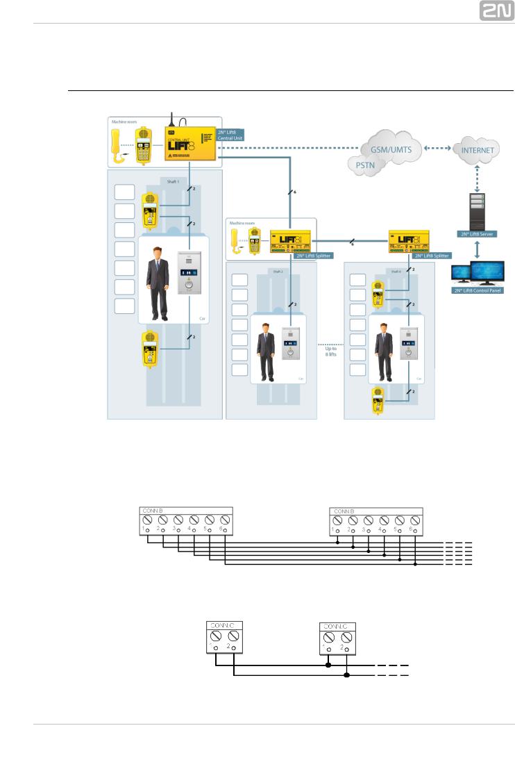
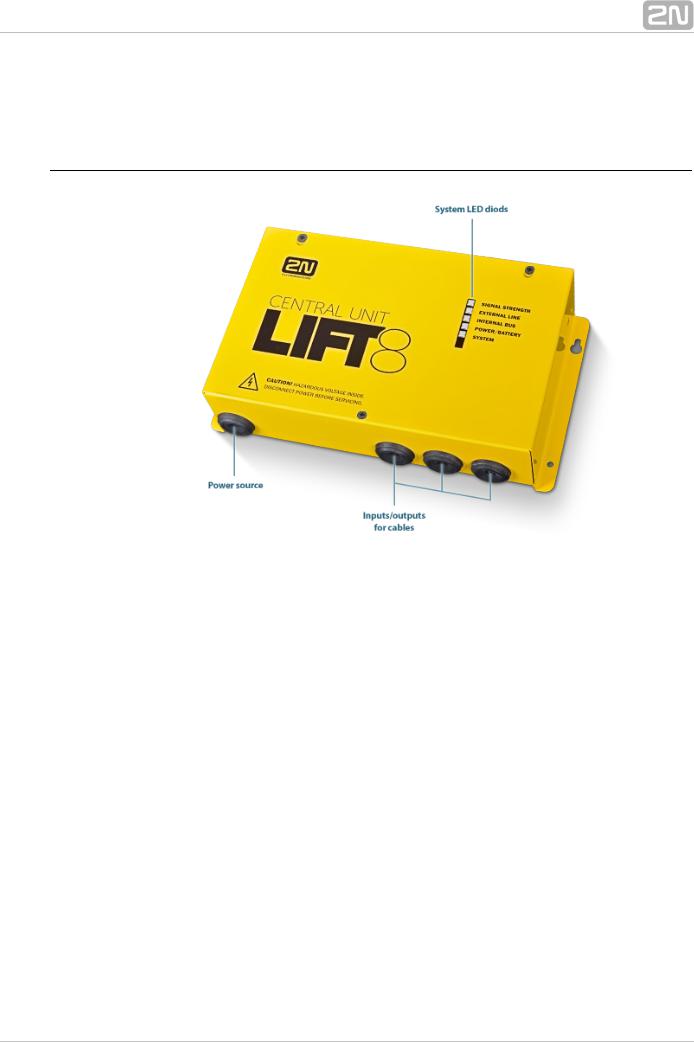
918600 2N® Lift8 Central Unit
Figure: 2N® Lift8 Central Unit
For connection of up to 8 lifts to a GSM/UMTS/PSTN line. Including a power EURO cable and rechargeable battery. USB interface for configuration.
2N® TELEKOMUNIKACE a.s., www.2n.cz |
8 |
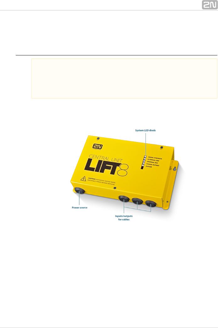
918620E 2N® Lift8 Splitter
Figure: 2N® Lift8 Splitter
For CU – lift audio unit interconnection.
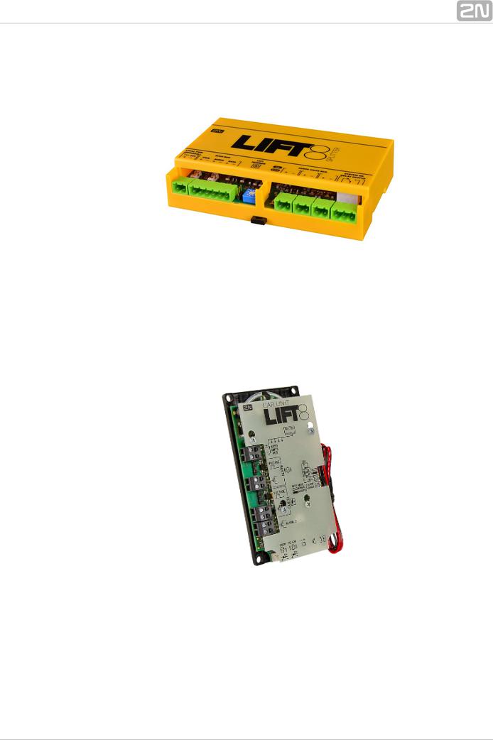
918610E 2N® Lift8 Audio Unit – Cabin Universal
(Normal version)
Figure: 2N® Lift8 Audio Unit – Cabin Universal
Audio unit electronics for lift cabin buiiding in. Including speaker and microphone (HandsFree). Connection terminals for all prescribed elements and door opening signal input (optional).
2N® TELEKOMUNIKACE a.s., www.2n.cz |
9 |
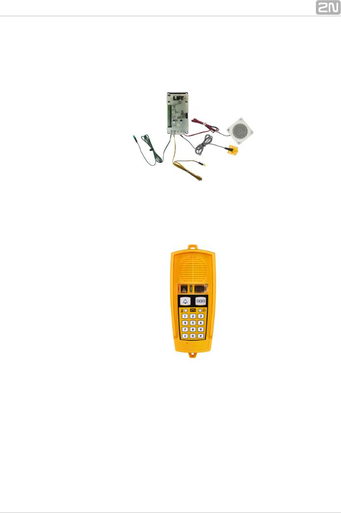
918610EX 2N® Lift8 Audio Unit – Cabin Universal – Cable Version
Contains LED, microphone and speaker connected to cables.
Figure: 2N® Lift8 Audio Unit – Cabin Universal – Cable Version
918611E 2N® Lift8 Audio Unit – Machine Room/Control Centre
Figure: 2N® Lift8 Audio Unit – Machine Room/Control Centre
Audio unit for the machine room/control centre. Contains receiver (optional) and keypad for easy control. Makes it possible to communicate with other system audio units and configure the CU without a PC. Equipped with an external siren connector. Can be shared by multiple lifts (shafts). Robust yellow cover.
2N® TELEKOMUNIKACE a.s., www.2n.cz |
10 |
918612E 2N® Lift8 Audio Unit – Shaft
Figure: 2N® Lift8 Audio Unit – Shaft
Audio unit for cabin roof and shaft or cabin bottom. Robust yellow cover. HandsFree mode, ALARM button and Triphony, LED indicators. Not intended for use in the cabin.
918613E 2N® Lift8 Audio Unit – Compact
Figure: 2N® Lift8 Audio Unit – Compact
Robust, heavy-duty design. Standard-sized ALARM button including signage for the blind and backlit pictograms (hardened glass). Easy cabin wall mounting. Easy 2-wire connection.
2N® TELEKOMUNIKACE a.s., www.2n.cz |
11 |
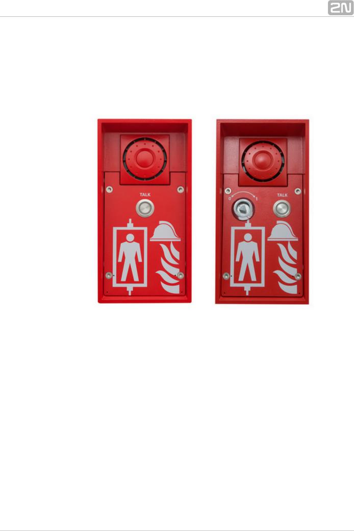
918615ZK 2N® Lift8 Audio Unit – Fireman (1 button)
918615E 2N® Lift8 Audio Unit – Fireman (knob + 1 push-to-talk button)
Figure: 2N® Lift8 Audio Unit – Fireman
Used for fire fighting operations. Activates top priority calls.
918610FZK 2N® Lift8 Audio Unit – Fireman DPS (1 button)
918619E 2N® Lift8 Audio Unit – Fireman DPS (knob + 1 push-to-talk button)
2N® TELEKOMUNIKACE a.s., www.2n.cz |
12 |
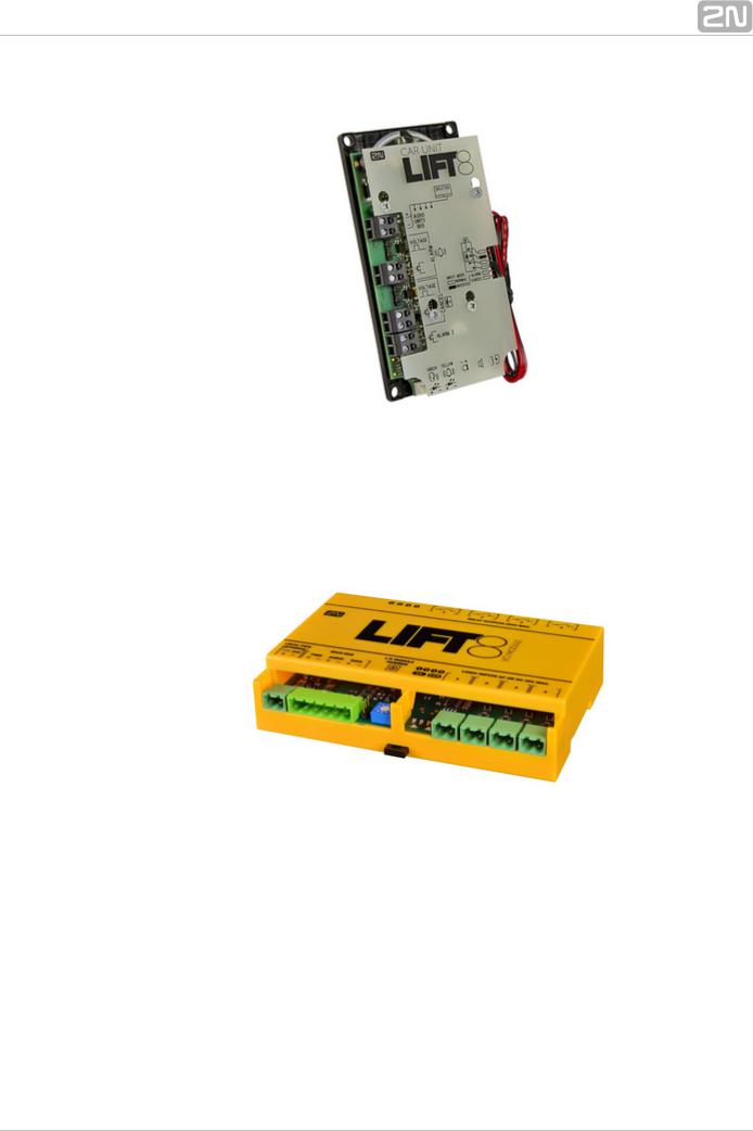
Figure: 2N® Lift8 Audio Unit – Fireman DPS
Used by fire fighting operations. Activates top priority calls.
918620E 2N® Lift8 I/O Module
Figure: 2N® Lift8 I/O Module
Contains logical inputs and switch relays.
2N® TELEKOMUNIKACE a.s., www.2n.cz |
13 |
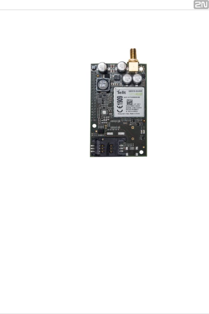
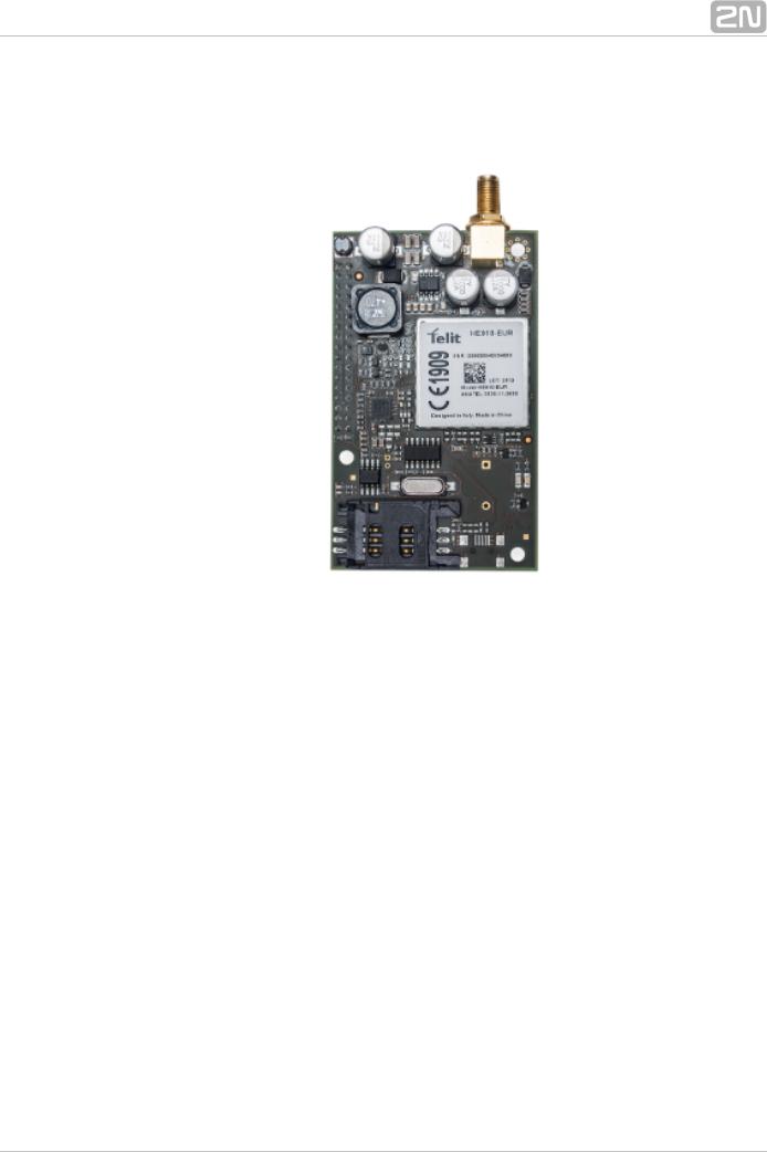
918650E 2N® Lift8 GSM Module
Figure: 2N® Lift8 GSM Module
For central unit connection via a mobile network. Optional data connection for remote system configuration.
2N® TELEKOMUNIKACE a.s., www.2n.cz |
14 |
918651E 2N® Lift8 UMTS Module
Figure: 2N® Lift8 UMTS Module
For central unit connection via a mobile network. Optional data connection for remote system configuration.
2N® TELEKOMUNIKACE a.s., www.2n.cz |
15 |
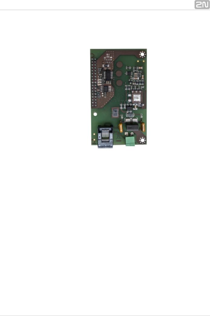
918652E 2N® Lift8 PSTN Module
Figure: 2N® Lift8 PSTN Module
For central unit connection via an analogue line.
2N® TELEKOMUNIKACE a.s., www.2n.cz |
16 |
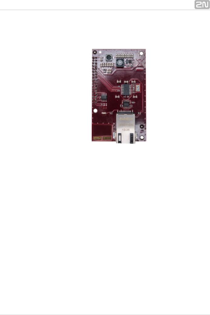
918653E 2N® Lift8 VoIP Module
Figure: 2N® Lift8 VoIP Module
For central unit connection via a VoIP line.
2N® TELEKOMUNIKACE a.s., www.2n.cz |
17 |
Cooperating 2N® Applications
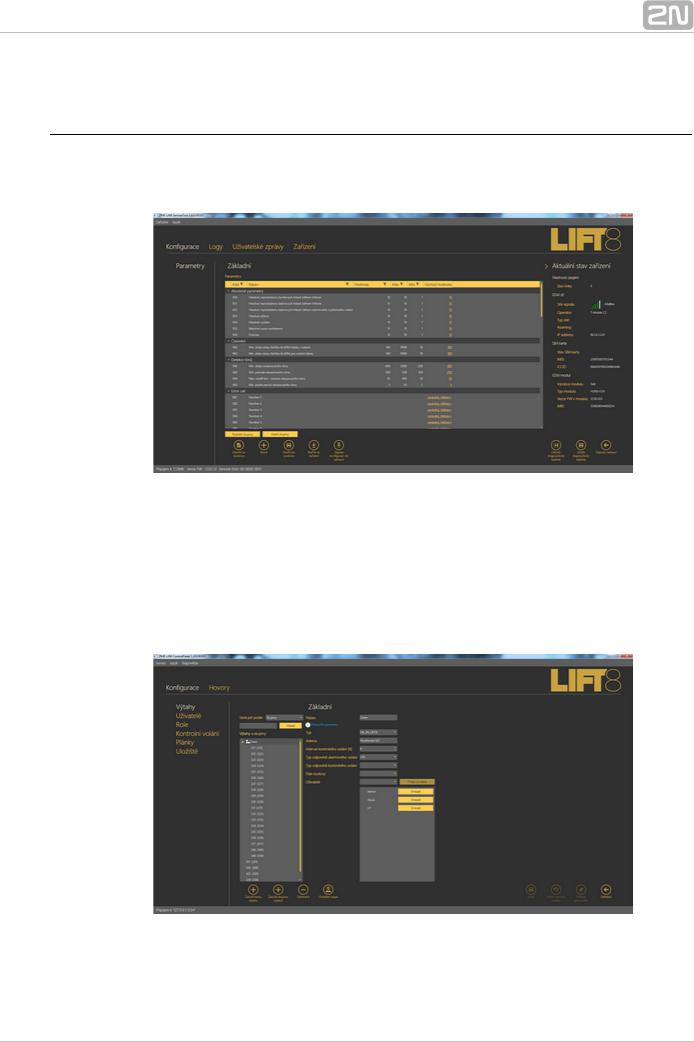
918700E 2N® Lift8 Service Tool
Figure: 2N® Lift8 Service Tool
The 2N® Lift8 Service Tool application is intended for remote supervision and configuration of the 2N® Lift8 communicators.
918700E 2N® Lift8 Control Panel
Figure: 2N® Lift8 Control Panel
The 2N® Lift8 Control Panel application is intended for administration of users, lifts
2N® TELEKOMUNIKACE a.s., www.2n.cz |
18 |
and authorisations.
918700E 2N® Lift8 Communicator
Figure: 2N® Lift8 Communicator
The 2N® Lift8 Communicator application is intended for receiving alarm calls by the dispatcher.
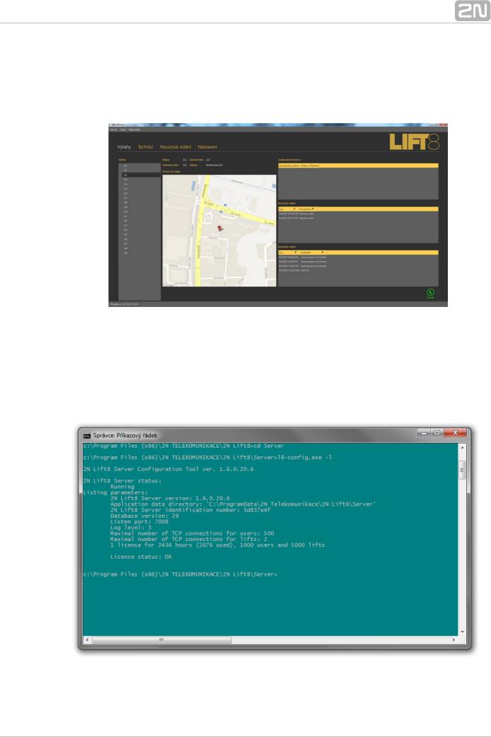
918700E 2N® Lift8 Server
Figure: 2N® Lift8 Server
2N® TELEKOMUNIKACE a.s., www.2n.cz |
19 |

The 2N® Lift8 Server application processes check calls and mediates communication between the CUs and PC applications.
Associated 2N® Products
918655E – 2N® Lift8 External Pictograms Driver
Figure: 2N® Lift8 External Pictograms Driver
Transforms the 2N® Lift8 cabin LED outputs into universal pilot lamps.
2N® TELEKOMUNIKACE a.s., www.2n.cz |
20 |
1.3 Upgrade
The table below sums up the User Manual upgrade changes made so far.
Manual
Description of changes
version
Firmware 1.0.0
1.0.0
 Basic version Firmware 1.5.0
 VoIP parameters added
1.5.0 Internal splitter four-lift configuration option
(up to four cabin units can be connected to one internal splitter with lift 1-4 identification)
Firmware 1.6.0
 Fireman
 I/O modules (inputs only)
 Configurable rechargeable battery capacity
1.6.0 New alarm call protocols added (shaft/announcer identification)
 Dial-in option (for PSTN modules with non-standard tones)
 CZ, EN, RU language support
 Important warnings - Upgrade Server Database from ver. 1.5.x to ver. 1.6.x
 Surveillance mode in the Control Panel
 Improvements in applications
2N® TELEKOMUNIKACE a.s., www.2n.cz |
21 |

1.4 Terms and Symbols Used
Symbols Used
The following symbols and pictograms are used in the manual:
 Safety
 Always abide by this information to prevent persons from injury.
 Warning
 Always abide by this information to prevent damage to the device.
 Caution
 Important information for system functionality.
 Tip
Tip
 Useful information for quick and efficient functionality.
 Note
Note
 Routines or advice for efficient use of the device.
Future Functions, New Features
The grey-marked text in this document designates the functions and features that are under preparation or development at present.
2N® TELEKOMUNIKACE a.s., www.2n.cz |
22 |

2. Description and Installation
The section is divided according to system components into the following subsections:
 2.1 PSTN/GSM/UMTS/VoIP Central Unit
 2.2 Splitter
 2.3 Audio Unit – Cabin Universal
 2.4 Audio Unit – Machine Room
 2.5 Audio Unit – Shaft
 2.6 Audio Unit – Compact
 2.7 PSTN Module
 2.8 GSM/UMTS Module
 2.9 VoIP Module
 2.10 Audio Unit – Fireman
 2.11 I/O Module
Each subsection includes:
 Description of Components
 Before You Start
 Fitting
 Electrical Wiring
2N® TELEKOMUNIKACE a.s., www.2n.cz |
23 |
2.1 PSTN/GSM/UMTS/VoIP Central Unit
Description
Figure: Central Unit
2N® TELEKOMUNIKACE a.s., www.2n.cz |
24 |

Figure: Central Unit Indication Elements
2N® TELEKOMUNIKACE a.s., www.2n.cz |
25 |
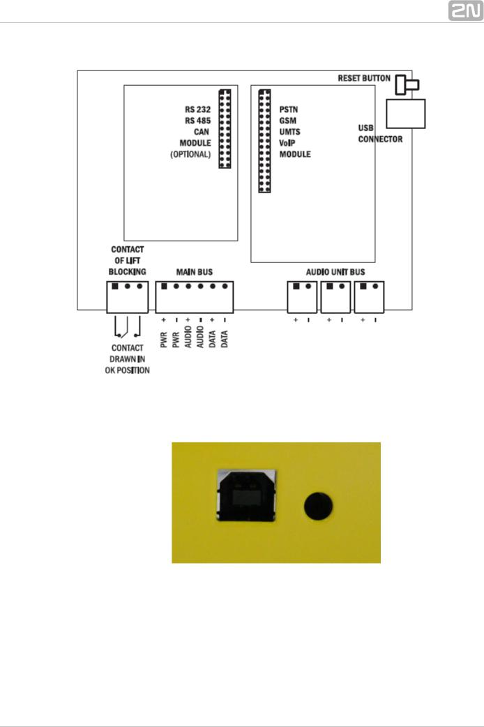
Figure: Central Unit Connectors
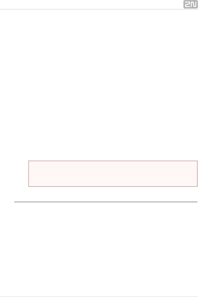
There are a USB connector and reset button to the right of the CU (see the figure below).
Figure: USB Connector and Reset Button
2N® TELEKOMUNIKACE a.s., www.2n.cz |
26 |
Reset button function
 Reset equipment – press the button quickly.
 Restore factory values – press and hold the button until all the LEDs turn red. Then release the button and wait until the SYSTEM LED flashes yellow. Now press the button quickly to delete all the user settings.
 Zero backup rechargeable battery life counter – press and hold the button until all the LEDs turn red. Then release the button and wait until the POWER/BATTERY LED flashes yellow. Now press the button quickly. Perform this function after replacing the backup rechargeable batteries with new ones only!
 Check system completeness – press and hold the button until all the LEDs turn red. Then release the button and wait until the INTERNAL BUS LED flashes yellow. Now press the button quickly to make the system supervise all the installed equipment (splitters, Audio Units etc.) for proper connection and function.
 Delete central unit software completely – press and hold the button until all the LEDs turn red. Then release the button and wait until the SYSTEM LED flashes red. Now press the button quickly. CAUTION: after performing this function you can only restore the normal function of the device using a PC!
USB Port Connection
Recommendation
 Do not keep your PC connected for a long time unless necessary to reduce the computer damage due voltage surge from the telephone line during storms, for example.
 Warning
 Do not open the CU during the warranty period.
 Open the CU only to replace the rechargeable batteries after the warranty period.
Before You Start
CU installation conditions
 The Central Unit (hereinafter referred to as CU) is not intended for outdoor use.
 Do not install the CU onto vibration-producing machines.
 Install the CU vertically to allow air flow for cooling purposes (never cover the CU with any cloth or install it in another closed box).
 You may install the CU into the lift switchboard unless the temperature exceeds the acceptable limit. Remember that a higher ambient temperature reduces the life of backup rechargeable batteries in the CU.
 It is recommended that the CU should be operated in the upright position with the cable openings at the bottom. Such mounting position ensures the lowest temperatures and thus the longest life of the rechargeable batteries. Horizontal mounting is also possible. The upright position with the cable openings at the top (upside down) is forbidden!
 After mounting the CU check that the equipment is firmly fixed in place and cannot come loose and drop down into the shaft.
2N® TELEKOMUNIKACE a.s., www.2n.cz |
27 |

Product Completeness Check
Check whether the product package is complete before installation:
 1 central unit
 1 main bus terminal
 4 bus connection terminals
 4 wall plugs
 4 wall plug screws
 8 cable ties
 1 battery connecting cables
 1 brief manual
 1 warranty sheet
  drilling template
CU Mounting
It is recommended to install the CU in a room that is secured against unauthorised persons, such as the lift machine room, switching station etc. On an easily accessible place there is a risk of telephone line misuse or SIM card misappropriation .
The CU is mounted on a wall with the included wall plugs and screws.
CU Electrical Installation
Putting in operation
1.Keep the CU disconnected from the mains.
2.Loosen the three screws on the upper cover of the CU.
3.Move the upper cover of the CU in such a way that you can remove it.
4.When removing the cover, proceed with caution, be careful about the earth wire connecting the cover with the CU bottom part. Do not disconnect the wire unless there is a reason to do so!
5.Using the slide-on terminals supplied with the device, connect the Audio Units, splitters (if there are 2 and more lift shafts) and other components of the system with the CU. Adhere to polarity!
6.Install a PSTN, GSM or UMTS module unless installed on the CU. Abide by the instructions given in the Instructions for Use of the given module (refer to Subs. 2.7 or 2.8).
7.Connect an analogue telephone line to the PSTN module if used (use a telephone connector or the terminal board on the module). Do not forget to connect an antenna to the GSM/UMTS module is used and insert a SIM card!
8.Connect the rechargeable battery jumper link (see the next subsection – Rechargeable Battery State Check) to activate the rechargeable battery function.
9.Replace the upper cover on the CU and tighten the cover fitting screws. Doing so make sure that the earthing wire is connected to the cover!
10.Connect the CU power cable to a 230V socket.
 Caution
 If you connect one lift shaft only, it is not necessary to connect the splitters. Use the splitters only if you want to connect 2 or more lift shafts.
2N® TELEKOMUNIKACE a.s., www.2n.cz |
28 |
Power supply
 The CU is powered by 100–240V mains power.
 Warning
 Never connect an AC source or unstabilised DC source to avoid CU damage.
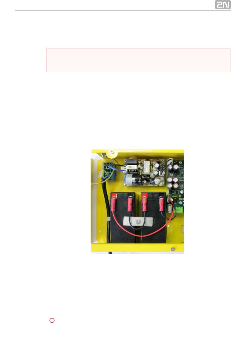
Rechargeable Battery Connection and State Check
Procedure:
1.Keep the CU disconnected from the mains.
2.Loosen the three screws on the upper cover of the CU.
3.Move the upper cover of the CU in such a way that you can remove it.
4.When removing the cover, proceed with caution, be careful about the earth wire connecting the cover with the CU bottom part. Do not disconnect the wire unless there is a reason to do so!
5.Interconnect the rechargeable batteries and connect them with the motherboard using a FASTON cable (see the figure below). Mind the polarity.
6.Replace the upper cover on the CU and tighten the cover fitting screws. Doing so make sure that the earthing wire is connected to the cover!
7.Connect the CU power cable to a 230V socket.
After plugging the CU into the socket the LED (Power/battery) should start to flash (charging). The CU charges the rechargeable batteries until fully charged. After some time the flashing green LED (charging) should change to a permanently illuminated green LED (battery charged).
2N® TELEKOMUNIKACE a.s., www.2n.cz |
29 |
 Warning
 Adhere to the polarity of the rechargeable batteries! When the polarity of the batteries is reversed, there is a danger of fire or explosion or damage to the CU electronics.
Rechargeable Batteries
 Caution
 If backup rechargeable batteries are used for the 2N® Lift8 power supply, the required backup of up to 1 h is guaranteed only if up to 20 audio units are connected in the system.
 The required 1h backup is not guaranteed if more than 20 audio units are installed.
Splitter – CU Bus Connection
Interconnect the CU and splitter using a 6-wire main bus (power + - , audio + - , data + - ). Mind the polarity.
2N® TELEKOMUNIKACE a.s., www.2n.cz |
30 |
Loading...