


ST.TM.E10100.1
Issue 1
ENGLISH (UK)
INSTRUCTION MANUAL
TT1260
Standard Definition
Professional Receiver/Decoder
Software Version 2.1 (and later)
TT1260/DIRBAS and Options
Typical TT1260 Satellite Receiver or Decoder

Preliminary Pages
ENGLISH (UK)
READ THIS FIRST!
If you do not understand the contents of this manual
DO NOT OPERATE THIS EQUIPMENT.
Also, translation into any EC official language of this manual can be made available, at your cost.
ITALIANO
LEGGERE QUESTO AVVISO PER PRIMO!
Se non si capisce il contenuto del presente manuale
NON UTILIZZARE L’APPARECCHIATURA.
È anche disponibile la versione italiana di questo manuale, ma il costo è a carico dell’utente.
SVENSKA
LÄS DETTA FÖRST!
Om Ni inte förstår informationen i denna handbok
ARBETA DÅ INTE MED DENNA UTRUSTNING.
En översättning till detta språk av denna handbok kan också anskaffas, på Er bekostnad.
NEDERLANDS
LEES DIT EERST!
Als u de inhoud van deze handleiding niet begrijpt STEL DEZE APPARATUUR DAN NIET IN WERKING.
U kunt tevens, op eigen kosten, een vertaling van deze handleiding krijgen.
PORTUGUÊS |
SUOMI |
LEIA O TEXTO ABAIXO ANTES DE MAIS NADA! |
LUE ENNEN KÄYTTÖÄ! |
Se não compreende o texto deste manual
NÃO UTILIZE O EQUIPAMENTO.
O utilizador poderá também obter uma tradução do manual para o português à própria custa.
Jos et ymmärrä käsikirjan sisältöä ÄLÄ KÄYTÄ LAITETTA.
Käsikirja voidaan myös suomentaa asiakkaan kustannuksella.
FRANÇAIS
AVANT TOUT, LISEZ CE QUI SUIT!
Si vous ne comprenez pas les instructions contenues dans ce manuel NE FAITES PAS FONCTIONNER CET APPAREIL.
En outre, nous pouvons vous proposer, à vos frais, une version française de ce manuel.
DANSK
LÆS DETTE FØRST!
Udstyret må ikke betjenes
MEDMINDRE DE TIL FULDE FORSTÅR INDHOLDET AF DENNE
HÅNDBOG.
Vi kan også for Deres regning levere en dansk oversættelse af denne håndbog.
DEUTSCH
LESEN SIE ZUERST DIESEN HINWEIS!
Sollte Ihnen der Inhalf dieses Handbuches nicht klar verständlich sein, dann
BEDIENEN SIE DIESE GERÄTE NICHT!
Eine Übersetzung des Handbuches in diese Sprache ist gegen Berechnung lieferbar.
ΕΛΛΗΝΙΚΑ
ÄΙΑΒΑΣΤΕ ΠΡÙΤΑ ΑΥΤΟ!
Αν δεν καταλÜβετε το περιεχüìενο αυτοý του βοηθÞìατοò/εγχειριδßου ΜΗΝ ΛΕΙΤΟΥΡΓΗΣΕΤΕ ΑΥΤΟΝ ΤΟΝ ΕΞΟΠΛΙΣΜΟ.
Επßσηò, αυτü το εγχειρßδιο εßναι διαθÝσιìο σε ìετÜφραση σε αυτÞ τη γλþσσα και ìπορεßτε να το αγορÜσετε.
ESPAÑOL
LEA ESTE AVISO PRIMERO!
Si no entiende el contenido de este manual
NO OPERE ESTE EQUIPO.
Podemos asimismo suministrarle una traducción de este manual al (idioma) previo pago de una cantidad adicional que deberá abonar usted mismo.
This document and the information contained in it is the property of TANDBERG Television Ltd and may be the subject of patents pending and granted. It must not be used for commercial purposes nor copied, disclosed, reproduced, stored in a retrieval system or transmitted in any form or by any means (electronic, mechanical, photocopying, recording or otherwise), whether in whole or in part, without TANDBERG Television’s prior written agreement.
2002 TANDBERG Television Ltd. All rights reserved.
Issue 1 first published in 2002 by:
TANDBERG TELEVISION LTD
REGISTERED ADDRESS:
UNIT 2 STRATEGIC PARK, COMINES WAY,
HEDGE END, SOUTHAMPTON,
HAMPSHIRE,
SO30 4DA
UNITED KINGDOM
Registered Company Number 03695535
Page ii |
Instruction Manual: TT1260 Standard Definition Professional Receiver/Decoder |
|
ST.TM.E10100.1 |

Preliminary Pages
List of Contents
Chapter 1: Introduction
This chapter identifies the equipment versions covered by this manual; describes the purpose of the equipment in a typical system; provides a summary of its main features; identifies the controls, indicators and connectors in a guided tour of the front and rear panels; and lists the available options.
Chapter 2: Installing the Equipment
This chapter provides a guide to the suitability of an installation; gives detailed procedures for the preparation, installation and configuration of the equipment including important safety information; provides pin-out details of the external connectors; and details the power-up/-down procedures.
Chapter 3: Operating the Equipment Locally
This chapter provides a guide to using the Front Panel LCD interface and details the setting-up, configuration and operating procedures.
Chapter 4: Alarms
This chapter provides a guide to configuring the alarm interface.
Chapter 5: Options
This chapter describes the available hardware and software options for the TT1260.
Chapter 6: Preventive Maintenance and Fault-finding
This chapter details routine maintenance tasks to be performed; provides general servicing advice, and information regarding warranty and maintenance; lists the error messages that may occur, and any appropriate Operator action to be taken; provides general fault-finding information for other types of problem which may be encountered.
Annex A: Glossary
Annex B: Technical Specification
Annex C: Menus
Annex D: Using the TT1260 with the TANDBERG Director System
Annex E: Language Abbreviations
Annex F: Factory Defaults
Annex G: Quick Reference Guide
Instruction Manual: TT1260 Standard Definition Professional Receiver/Decoder |
Page iii |
ST.TM.E10100.1 |
|

Preliminary Pages
Index
Forms
Service/Repair Order Form
Page iv |
Instruction Manual: TT1260 Standard Definition Professional Receiver/Decoder |
|
ST.TM.E10100.1 |

Preliminary Pages
About this Manual
This manual provides instructions and information for the installation and operation of the TT1260 1U digital integrated Receiver/Decoder (IRD). It should be kept in a safe place for reference during the life of the equipment. Further copies of this manual can be ordered from the address shown on page vii. If passing the equipment to a third party, pass on the relevant documentation also.
Issues of this Manual
Issues of this manual are listed below:
Issue |
Date |
Software Version |
Comments |
|
|
|
|
1 |
March 2002 |
2.1 |
Initial release. |
|
|
|
|
The following associated manual is also available:
ST.QR.E10100: Quick Reference Guide
Acknowledgements
General
All best endeavours have been made to acknowledge registered trademarks and trademarks used throughout this manual. Any notified omissions will be rectified in the next issue of this manual.
Some trademarks may be registered in some countries but not in others. In general, the situation in the UK will prevail throughout TANDBERG Television Limited manuals.
Registered trademarks and trademarks used are acknowledged below and marked with their respective symbols. However, they are not marked within the text of this manual.
Trademarks
Alteia™ is a trademark of TANDBERG Television Limited.
Registered Trademarks
VideoGuard® is a registered trademark of NDS Limited.
Dolby Digital® and AC-3® are registered trademarks of Dolby Laboratories Licensing Corporation.
Instruction Manual: TT1260 Standard Definition Professional Receiver/Decoder |
Page v |
ST.TM.E10100.1 |
|

Preliminary Pages
Warnings, Cautions and Notes
Heed Warnings
All warnings on the product and in the operating instructions should be adhered to. The manufacturer can not be held responsible for injuries or damage where warnings and cautions have been ignored or taken lightly.
Read Instructions
All the safety and operating instructions should be read before this product is operated.
Follow Instructions
All operating and use instructions should be followed.
Retain Instructions
The safety and operating instructions should be retained for future reference.
WARNINGS...
WARNINGS GIVE INFORMATION WHICH, IF STRICTLY OBSERVED, WILL PREVENT PERSONAL INJURY OR DEATH, OR DAMAGE TO PERSONAL PROPERTY OR THE ENVIRONMENT. THEY ARE BOXED AND SHADED FOR EMPHASIS, AS IN THIS EXAMPLE, AND ARE PLACED IMMEDIATELY PRECEDING THE POINT AT WHICH THE READER REQUIRES THEM.
CAUTIONS...
Cautions give information that if strictly followed, will prevent damage to equipment or other goods. They are boxed for emphasis, as in this example, and are placed immediately preceding the point at which the reader requires them.
NOTES...
Notes provide supplementary information. They are highlighted for emphasis, as in this example, and are placed immediately after the relevant text.
EMC Compliance
This equipment is certified to the EMC requirements detailed in Annex B, Technical Specification. To maintain this certification, only use the leads supplied or if in doubt contact TANDBERG Customer Services.
Page vi |
Instruction Manual: TT1260 Standard Definition Professional Receiver/Decoder |
|
ST.TM.E10100.1 |

Preliminary Pages
Contact Information
TANDBERG Television Customer Services
Support Services
Our primary objective is to provide first class customer care that is tailored to your specific business and operational requirements. All levels are supported by one or more service performance reviews to ensure the perfect partnership between TANDBERG Television and your business.
Levels of Support
We offer a number of support service levels so you can choose the one most appropriate to your business requirements.
For the initial 12 months, Bronze Level Support is provided free on this product. An extended time period can be purchased for this level.
Silver Level Support extends the coverage to include on-site support, preventive maintenance and discount on predesigned training.
The Gold Level Support gives an enhanced support package. It builds on the Silver Level by including advanced repair exchange, an account focused engineer, version migration support and further discount on predesigned training.
Where to Find Us
Europe, Middle East |
+44 |
(0) 23 8048 4455 |
and Africa: |
Fax: +44 (0) 23 8048 4467 |
|
|
fieldservice@tandbergtv.com |
|
Norway: |
+47 |
6711 6200 |
Americas: |
+1 (321) 308 0470 |
|
|
fieldservice-americas@tandbergtv.com |
|
China: |
+86 |
10 6539 1109 (Beijing) |
|
+ 852 2899 7000 (Hong Kong) |
|
|
fieldservice-asia@tandbergtv.com |
|
Australia/NZ: |
+61 |
2 9356 8599 |
|
fieldservice-australia@tandbergtv.com |
|
Germany: |
+49 |
8996 999 870 |
Poland: |
+48 |
58 3000 940 |
Internet Address: |
http://www.tandbergtv.com |
|
Instruction Manual: TT1260 Standard Definition Professional Receiver/Decoder |
Page vii |
ST.TM.E10100.1 |
|

Preliminary Pages
Technical Training
Training Courses
TANDBERG Television provides a wide range of training courses on the operation and maintenance of our products and on their supporting technologies. TANDBERG can provide both regularly scheduled courses and training tailored to individual needs. Courses can be run either at your premises or at one of our dedicated training facilities.
Where to Find Us
For further information on TANDBERG Television's training programme please contact us:
International Telephone: |
+44 23 8048 4229 |
International Facsimile |
+44 23 8048 4467 |
E-mail Address: |
training@tandbergtv.com |
Internet Address |
http://www.tandbergtv.com |
Customer Services and Technical Training Postal Address
Tandberg Television
Unit 2
Strategic Park
Comines Way
Hedge End
Southampton
Hampshire
SO30 4DA
United Kingdom
Return of Equipment
If you need to return equipment for repair, please contact the Customer Services Helpdesk on +44 (0) 23 8048 4455. A Returns Authorisation Number (RAN) will be issued and full details of the unit will be logged.
Technical Publications
If you need to contact TANDBERG Television Technical Publications regarding this publication, e-mail: techpubs@tandbergtv.com.
Page viii |
Instruction Manual: TT1260 Standard Definition Professional Receiver/Decoder |
|
ST.TM.E10100.1 |

Contents
1.1 Scope of this Manual................................................. |
1-3 |
||
|
1.1.1 Who Should Use this Manual ....................... |
1-3 |
|
|
1.1.2 What this Manual Describes ......................... |
1-3 |
|
|
|
Identifying the Equipment ............................. |
1-3 |
|
|
Marketing Codes........................................... |
1-4 |
|
|
Software Versions......................................... |
1-4 |
1.2 |
Summary of Features................................................ |
1-6 |
|
|
1.2.1 |
Main Features............................................... |
1-6 |
|
1.2.2 |
Inputs............................................................ |
1-8 |
|
|
ASI Inputs (Decoders) .................................. |
1-8 |
|
|
L-Band Inputs ............................................... |
1-8 |
|
|
Remote Control............................................. |
1-8 |
|
|
Frame Synchronisation................................. |
1-8 |
|
1.2.3 |
Outputs ......................................................... |
1-8 |
|
|
Transport Stream Outputs ............................ |
1-8 |
|
|
Video Outputs............................................... |
1-8 |
|
|
Audio Outputs............................................... |
1-8 |
|
|
Data Output .................................................. |
1-8 |
|
|
Alarm Output................................................. |
1-8 |
|
1.2.4 Conditional Access and Scrambling ............. |
1-9 |
|
1.3 |
The Satellite Receiver ............................................. |
1-10 |
|
|
1.3.1 |
Typical Satellite System.............................. |
1-10 |
|
1.3.2 |
Input Connections....................................... |
1-11 |
|
1.3.3 What the Satellite Receiver Does ............... |
1-11 |
|
1.3.4Over-air Software Download
|
(TANDBERG Director Systems) ................. |
1-12 |
1.4 The Decoder ........................................................... |
1-13 |
|
1.4.1 |
Typical Decoder System............................. |
1-13 |
1.4.2 |
Input Connections....................................... |
1-14 |
1.4.3 What the Decoder Does ............................. |
1-14 |
|
Chapter 1
Introduction
1.5 |
TT1260 Control Modes............................................ |
1-14 |
|
|
1.5.1 |
Introduction ................................................. |
1-14 |
|
1.5.2 Front Panel (Local) Modes.......................... |
1-15 |
|
|
1.5.3 Serial Remote Control Mode....................... |
1-15 |
|
|
1.5.4 TANDBERG Director NCP Control Mode.... |
1-15 |
|
1.6 |
Guided Tour............................................................. |
1-16 |
|
|
1.6.1 |
Construction ................................................ |
1-16 |
|
1.6.2 |
Front Panel Controls ................................... |
1-16 |
|
1.6.3 |
Front Panel LEDs........................................ |
1-16 |
|
1.6.4 Bit Error Ratio Measurement....................... |
1-16 |
|
|
1.6.5 Conditional Access and Scrambling |
|
|
|
|
Options........................................................ |
1-17 |
|
|
VideoGuard Director.................................... |
1-17 |
|
|
Remote Authorisation System (RAS 1) ....... |
1-17 |
|
|
Basic Interoperable Scrambling System |
|
|
|
(BISS).......................................................... |
1-17 |
|
1.6.6 |
Rear Panel .................................................. |
1-17 |
List of Figures |
|
||
Figure 1.1: Front View of a TT1260 Satellite Receiver.................. |
1-3 |
||
Figure 1.2: Make-up of TT1260 Marketing Numbers..................... |
1-3 |
||
Figure 1.3: Typical Satellite Compression System ...................... |
1-10 |
||
Figure 1.4: What the Satellite Receiver Does.............................. |
1-11 |
||
Figure 1.5: Typical Download Transmission System.................. |
1-12 |
||
Figure 1.6: Typical Compression System.................................... |
1-13 |
||
Figure 1.7: Role of the Decoder................................................... |
1-14 |
||
Figure 1.8: Front Panel States..................................................... |
1-15 |
||
Figure 1.9: Front Panel Controls.................................................. |
1-16 |
||
Figure 1.10: TT1260 Decoder Rear Panel................................... |
1-17 |
||
Instruction Manual: TT1260 Standard Definition Professional Receiver/Decoder |
Page 1-1 |
ST.TM.E10100.1 |
|

Introduction
List of Tables |
|
Table 1.3: Main Features of the Decoder Range........................... |
1-5 |
Table 1.1: Hardware Marketing Codes........................................... |
1-4 |
Table 1.4: Main Features of the Satellite Receiver Range ............ |
1-5 |
Table 1.2: Software Key Marketing Codes..................................... |
1-4 |
|
|
Page 1-2 |
Instruction Manual: TT1260 Standard Definition Professional Receiver/Decoder |
|
ST.TM.E10100.1 |
Introduction
1.1Scope of this Manual
1.1.1Who Should Use this Manual
This manual is written for operators/users of the TT1260 Professional Receivers and Decoders. It describes the unit’s functions and operation. The manual is written to assist in the installation and day-to-day care and operation of the unit. Maintenance information requiring the covers to be removed is not included.
CAUTION...
Removing the covers of this equipment may invalidate the warranty.
1.1.2What this Manual Describes
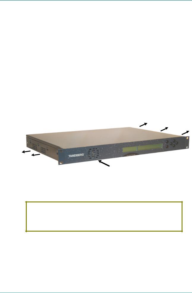
Identifying the Equipment
The Receivers and Decoders are designated by the marketing numbers shown in Table 1.1.
Figure 1.1: Front View of a TT1260 Satellite Receiver
The Marketing Number and fitted options are defined by the following:
HWO: Hardware Option
SWO: Software Option
HDC: Hardware Daughter Card
See Table 1.1 for a description of each option
TT1260/xxx/xxxx
Figure 1.2: Make-up of TT1260 Marketing Numbers
Instruction Manual: TT1260 Standard Definition Professional Receiver/Decoder |
Page 1-3 |
ST.TM.E10100.1 |
|

Introduction
Marketing Codes
Table 1.1 gives a description of each hardware Marketing Code and Table 1.2 gives a description of each software key Marketing Code.
Table 1.1: Hardware Marketing Codes
Option |
Marketing Codes |
Engineering |
Description |
Number |
|
Number |
|
|
|
|
|
|
TT1260/DIRBAS |
E10100 |
TT1260 Base unit with Director Smart Card reader |
|
|
|
hardware, chassis |
|
TT1260/HDC/ALRM |
S12316 |
Alarm Relay Card |
|
|
|
|
3 |
TT1260/HWO/ASI |
S12495 |
ASI Input Card, chassis backplate for ASI Input Card |
|
|
|
|
4 |
TT1260/HWO/QPSK |
S12496 |
QPSK Input Card, chassis backplate for QPSK Card |
|
|
|
|
5 |
TT1260/HWO/HM |
S12501 |
8PSK/16QAM Input Card, QPSK, 8PSK and 16QAM |
|
|
|
DVB-S capable, chassis backplate |
6 |
TT1260/HWO/HSDATA |
S12595 |
High Speed RS-422 Data Enabler Card |
|
|
|
|
|
TT1260/CABLE/XLR |
S12667 |
Cable for 9-pin D-type to XLR stereo pair |
|
|
||
Table 1.2: Software Key Marketing Codes |
|
||
Option |
Marketing Codes |
Engineering |
Description |
Number |
|
Number |
|
|
|
|
|
|
TT1260/SWO/16QAM |
S12666 |
Software key for TT1260/HWO/HM, enabling QPSK, 8PSK, |
|
|
|
16QAM |
|
TT1260/SWO/8PSK |
S12666 |
Software key for TT1260/HWO/HM, enabling QPSK and |
|
|
|
8PSK |
|
TT1260/SWO/SP |
S12666 |
Software key for Signal Protection CA |
|
|
|
|
|
TT1260/SWO/RAS |
S12666 |
Software key for RAS Mode-1 CA |
|
|
|
|
|
TT1260/SWO/DIR |
S12666 |
Software key for VideoGuard Director CA/TANDBERG |
|
|
|
Director NCP |
|
TT1260/SWO/BISS |
S12666 |
Software key for BISS-1/BISS-E |
|
|
|
|
Software Versions
This manual has been written to cover the functions of software versions 2.1 and later. To verify the installed version access the Systems Menu (#6). The menus are described in Annex C, Menus.
Page 1-4 |
Instruction Manual: TT1260 Standard Definition Professional Receiver/Decoder |
|
ST.TM.E10100.1 |

Introduction
Table 1.3: Main Features of the Decoder Range
Marketing |
|
Inputs |
|
Input Data-rate |
Coding |
Digital |
|
Code |
|
|
|
|
|
|
Outputs |
|
|
|
|
|
|
||
TT1260/HWO/ASI |
2 x ASI |
|
0.350-160 Mbit/s |
|
|
||
|
|
|
|
||||
Table 1.4: Main Features of the Satellite Receiver Range |
|
|
|
||||
|
|
|
|
|
|
|
|
|
Marketing |
Inputs |
Input Frequency |
Input Symbol rate |
FEC Rates |
Digital |
|
|
Code |
|
|
|
|
|
Outputs |
|
|
|
|
|
|
|
|
Satellite |
TT1260/HWO/HM |
2 x 8PSK |
950 – 2150 MHz |
1 – 44.5 Msymbols/s |
QPSK: |
|
|
8PSK |
TT1260/HWO/8PSK |
|
|
|
1/2, 2/3, 3/4, |
|
|
|
|
|
|
|
|||
|
|
|
|
|
|
5/6, 7/8 |
|
|
|
|
|
|
|
8PSK: |
|
|
|
|
|
|
|
2/3, 5/6, 8/9 |
|
|
|
|
|
|
|
|
|
Satellite |
TT1260/HWO/HM |
2 x |
950 – 2150 MHz |
1 – 44.5 Msymbols/s |
QPSK: |
|
|
8PSK |
TT1260/SWO/16QAM |
8PSK/16QAM |
|
|
1/2, 2/3, 3/4, |
|
|
16QAM |
|
|
|
|
|
5/6, 7/8 |
|
|
|
|
|
|
|
|
|
|
|
|
|
|
|
8PSK: |
|
|
|
|
|
|
|
2/3, 5/6, 8/9 |
|
|
|
|
|
|
|
16QAM: |
|
|
|
|
|
|
|
3/4, 7/8 |
|
|
|
|
|
|
|
|
|
Satellite |
TT1260/HWO/QPSK |
2 x QPSK |
950 – 2150 MHz |
1 – 44.5 Msymbols/s |
QPSK: |
|
|
QPSK |
|
|
|
|
|
1/2, 2/3, 3/4, |
|
|
|
|
|
|
|
|
|
|
|
|
|
|
|
5/6, 7/8 |
|
|
|
|
|
|
|
|
|
NOTE…
All models have analogue outputs as standard.
Instruction Manual: TT1260 Standard Definition Professional Receiver/Decoder |
Page 1-5 |
ST.TM.E10100.1 |
|

Introduction
1.2Summary of Features
1.2.1Main Features
The TT1260 is fully compliant with the appropriate sections of the MPEG-21, DVB-S2 and DSNG3 specifications and offers the following features:
Front Panel Controls and Indications:
A vertical split two line x 40 character back-lit dot matrix LCD display with pushbuttons for Up, Down, Left, Right, Edit, and Save to provide information and operator choice entry
LEDs to indicate lock and general alarm conditions
Service Selection:
Chosen from a menu list of available services carried in the currently received transport stream
Up to 40 pre-selected choices can be stored within the unit
Multiple Inputs (Satellite Receivers)
L-band Satellite Receivers have two inputs (either QPSK or QPSK, 8PSK and 16QAM)
Video Decoding:
4:2:0 mode support video resolutions up to 720 pixels x 576 active lines (25 frame/s) or 720 pixels x 480 active lines (30 frame/s)
4:2:2 mode support video resolutions up to 720 pixels x 608 active lines (25 frame/s) or 720 pixels x 512 active lines (30 frame/s)
Support for PAL- I, B, G, D, PAL- N, PAL- M, and NTSC-M (with pedestal or without) composite video output via two 75Ω BNC connectors
Audio Decoding:
Sampling rates 32, 44.1, 48 kHz
All MPEG-1 data rates
All Dolby Digital AC-3 data rates, decoded as a Dolby Stereo downmix
Linear uncompressed audio, data rates as defined by SMPTE 302M
Data:
Low Speed Data: RS-232 asynchronous (up to 38.4 kbit/s)
High Speed Data: RS-422 synchronous (up to 2.048 Mbit/s) (option)
Transport Stream Output:
ASI transport stream output with maximum data rate 160 Mbit/s
1Moving Pictures Expert Group: MPEG-2 specification ISO 13818.
2European Digital Video Broadcasting (DVB) Project. EN 300 421 Digital broadcasting systems for television, sound and data services: Framing structure, channel coding and modulation for the 11/12 GHz satellite service.
3European Digital Video Broadcasting (DVB) Project : EN 301 210 Digital broadcasting systems for television, sound and data services: Framing structure, channel coding and modulation for digital satellite news gathering (DSNG) and other contribution applications by satellite.
Page 1-6 |
Instruction Manual: TT1260 Standard Definition Professional Receiver/Decoder |
|
ST.TM.E10100.1 |

Introduction
Conditional Access/Scrambling:
Remote Authorisation System (RAS) version I
EBU Basic Interoperable Scrambling System (BISS) Mode-E
EBU Basic Interoperable Scrambling System (BISS) Mode-1
VideoGuard Director
TANDBERG Television Signal Protection
TANDBERG Director system:
Over-air remote control is available if the TT1260 is used as part of a TANDBERG Director system (Over-air software downloading, Re-start, Tuning and Retuning etc.)
NOTES…
1.The TANDBERG Director system GUI counts the inputs from zero (i.e. 0, 1).
2.TANDBERG Director versions 4 and onward allow selection of the L-band (RF) input.
Remote Control:
RS-232 or RS-485
NCP Over-the-Air remote control via VideoGuard Director
When the remote control is active, front panel control is disabled but status information is still available (protocol is available from TANDBERG Television Limited)
Clock/Calendar:
Available to co-ordinate universal and local time
Constantly updated when locked to a valid transport stream
Transport Stream Demultiplexing:
Maximum capability is 160 Mbit/s, depending on CA in use and input front end
Video Decoding:
Maximum Video Demultiplexing capability of 50 Mbit/s
Audio:
Audio embedding in the digital video output
Vertical Blanking Interval (VBI) signalling support:
World System Teletext (WST)
Support for Closed Captions and VITS/ITS/VITC
Inverted Teletext
Video Programming System (VPS)/Programme Delivery Control (PDC)
Neilson Coding AMOL 1 and AMOL 2
Vertical Interval Time Code (VITC)
Video Index
Video Test Pattern Generator
Error Data Handling (EDH):
EDH is supported on the SDI (digital video) output
Frame Synchronisation of digital video output to analogue input
Instruction Manual: TT1260 Standard Definition Professional Receiver/Decoder |
Page 1-7 |
ST.TM.E10100.1 |
|

Introduction
Control Methods:
Front Panel User Interface
Asynchronous serial remote control
Over-air remote control (TANDBERG Director system) (optional)
1.2.2Inputs
ASI Inputs (Decoders)
Two BNC connectors support both byte-mode and single packet burst mode.
L-Band Inputs
Two F-type connectors connect the L-band output of a suitable LNB either directly or via a suitable attenuator giving lightning and surge protection.
Remote Control
A 9-way D-type, male connector used to connect to a PC and can be switched between the RS-232 and RS-485 input standards.
Frame Synchronisation
A BNC connector accepts a composite video input to which the video output timing can be synchronised.
1.2.3Outputs
Transport Stream Outputs
Two BNC connectors output ASI transport streams with a maximum data rate of 160 Mbit/s.
Video Outputs
Two analogue composite video outputs carried on BNC connectors.
Two digital video outputs carried on BNC connectors.
Audio Outputs
Two 9-way D-type, female connectors decode two PES streams of audio from the transport stream. The audio outputs simultaneous analogue and digital. The digital mode can be changed via the user interface.
Data Output
RS-232 asynchronous low-speed data output carried on a 9-way, D-type, female connector.
RS-422 synchronous high-speed data output carried on a 9-way, D-type, female connector.
Alarm Output
A 9-way D-type connector for alarm and failure monitoring is carried out within the equipment. This produces a summary alarm signal that lights the general front-panel ALARM LED.
Page 1-8 |
Instruction Manual: TT1260 Standard Definition Professional Receiver/Decoder |
|
ST.TM.E10100.1 |

Introduction
There is a 25-way D-type connector on the optional Alarm Relay Card (TT1260/HDC/ALRM) with six relays for failure monitoring for NCP over-air. The operator can define (using the Alarm Menu pages) which alarm conditions that drive the relays and also the general front-panel ALARM
LED. This is described in Chapter 4, Alarms and Annex C, Menus.
1.2.4Conditional Access and Scrambling
The transport stream received by the IRD may be encrypted. The CA system is used to decrypt the required components of the transport stream so that they can be decoded.
The following Conditional Access and Scrambling options are available for the TT1260 range of Satellite Receivers and Decoders:
No Conditional Access
Basic Interoperable Scrambling System (BISS) Mode-1 and Mode-E only.
VideoGuard Director and BISS
Remote Authorisation System (RAS) and BISS
VideoGuard Director, RAS and BISS
Signal Protection
When the CA system uses a Smart Card, access by the user is via the back panel of the IRD.
Instruction Manual: TT1260 Standard Definition Professional Receiver/Decoder |
Page 1-9 |
ST.TM.E10100.1 |
|
Introduction
1.3The Satellite Receiver
1.3.1Typical Satellite System
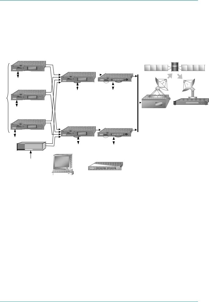
The TT1260 Satellite Receiver is a component of the MPEG-2/DVB compliant range of TANDBERG Television equipment. It is designed for use by broadcasters and distributors of video, audio and data services over satellite.
evolution 5000 Encoder (1)
1 |
2 |
3 |
4 |
5 |
6 |
7 |
8 |
9 |
0 |
* |
|
Ethernet
evolution 5000
Encoder (2)
Local |
0 |
* |
|
|
1 |
2 |
3 |
|
4 |
5 |
6 |
|
7 |
8 |
9 |
Inputs |
|
|
|
Ethernet
evolution 5000
Encoder (n)
1 |
2 |
3 |
4 |
5 |
6 |
7 |
8 |
9 |
0 |
* |
|
evolution 5000 |
|
|
evolution 5000 |
||
Multiplexer (Main) |
|
|
Modulator (Main) |
||
|
|
|
|
|
|
|
|
|
|
|
|
1 |
2 |
3 |
4 |
5 |
6 |
7 |
8 |
9 |
0 |
* |
|
|
|
|
|
|
|
|
|
|
|
|
|
|
|
|
|
|
|
|
|
|
|
|
|
|
|
|
|
|
|
|
|
|
|
|
|
|
|
|
|
|
|
|
|
|
|
|
|
|
|
|
|
|
|
|
|
|
|
|
|
|
|
|
|
|
|
|
|
|
|
|
|
|
|
|
|
|
|
|
|
|
|
|
|
|
|
|
|
|
|
|
|
|
|
|
|
|
|
|
|
|
|
|
|
|
|
|
|
|
|
|
|
|
|
|
|
|
|
|
|
|
|
|
|
|
|
|
|
|
|
|
|
|
|
|
|
|
|
|
|
|
|
|
|
|
|
|
|
|
|
|
|
|
|
|
|
|
|
|
|
|
|
Ethernet |
|
Ethernet |
|
|
|
|
|
|||||||||||||||||||
|
Control |
|
Control |
|
|
|
|
|
|
|
|
|
|
|
|
|
||||||||||
|
|
|
|
|
|
|
|
|
|
|
|
|
|
|||||||||||||
|
|
|
||||||||||||||||||||||||
|
|
|
|
|
|
|
|
|
|
|
|
|
|
|
|
|
|
|
|
|
|
|
|
|
|
|
|
|
|
|
|
|
|
|
|
|
|
|
|
|
|
|
|
|
|
|
|
|
|
|
|
|
|
|
|
|
|
|
|
|
|
|
|
|
|
|
|
|
Up-converter |
|
|
|||||||||
|
evolution 5000 |
|
|
|
|
|
|
|
|
|
|
|
and HPA |
|
|
|||||||||||
|
|
evolution 5000 |
|
|
||||||||||||||||||||||
Multiplexer (Standby) |
|
|
|
|||||||||||||||||||||||
|
Modulator (Standby) |
|
|
|||||||||||||||||||||||
|
|
|
|
|
|
|
||||||||||||||||||||
|
|
|
|
|
|
|
|
|
|
|
|
|
|
|
|
|
|
|
|
|
|
|
|
|
|
|
Ethernet
Transport Stream |
Processor |
MPEG-2
Transport
Stream
1 |
2 |
3 |
4 |
5 |
6 |
7 |
8 |
9 |
0 |
* |
|
|
|
|
|
|
|
|
|
|
|
|
|
|
|
|
|
|
|
|
|
|
|
|
|
Ethernet |
Ethernet |
||||
Control |
Control |
||||
10BaseT


 Ethernet
Control
 Ethernet Hub evolution 5000
Multiplex Element Manager
TANDBERG |
TT1260 |
Figure 1.3: Typical Satellite Compression System
Page 1-10 |
Instruction Manual: TT1260 Standard Definition Professional Receiver/Decoder |
|
ST.TM.E10100.1 |
Introduction
1.3.2Input Connections
The Satellite Receiver interfaces directly to Low-Noise Block (LNB) and accepts an intermediate frequency (IF) input in the band 950 - 2150 MHz (L-band) for operation in the specified symbol-rate range (see
Annex B, Technical Specification). The unit can provide dc power and polarisation switching to the LNB.
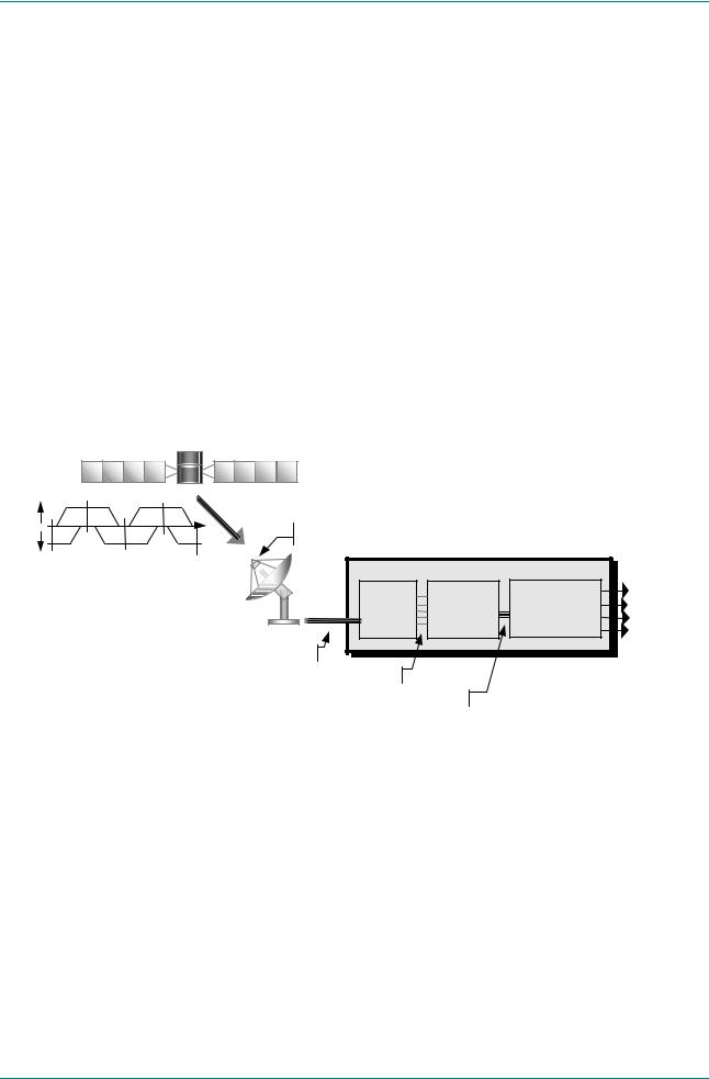
1.3.3What the Satellite Receiver Does
The Receiver can be tuned to a specified satellite channel frequency and polarisation. The input is down-converted via a Low-Noise Block (LNB) to provide an L-band input to the Receiver. The front-end tuning is microprocessor controlled with a frequency synthesised local oscillator. A software tuning and acquisition algorithm resolves translation errors (mainly due to the LNB).
The signal is then passed to a demodulator that recovers the signal using soft-decision decoding. The resulting stream is Reed-Solomon decoded and descrambled to provide inputs to the Decoder circuit. The received channel may contain multiple services, therefore the Receiver’s demultiplexer is configured to select a single video service and other audio/data components and present them at the output.
horizontal |
fn+1 |
SHF |
fn+3 |
|
|
|
|
|
|
|
|
|
|
|
|
polarisation |
|
|
Low-Noise Block |
|
|
|
|
vertical |
|
|
|
|
|
||
|
|
|
|
|
|
|
|
polarisation |
fn |
fn+2 |
fn+4 |
|
TT1260 Satellite Receiver |
|
|
|
|
|
|
|
|
||
|
|
|
|
Tune to a |
Select a |
Select the |
Video |
|
|
|
L-band |
satellite |
service from |
components from |
Audio |
|
|
|
channel |
the satellite |
the chosen service |
Data |
|
|
|
|
|
||||
|
|
|
|
|
channel |
|
Transport Stream |
|
|
|
Multiple satellite channels |
|
|
|
|
|
|
|
Multiple services on the tuned satellite channel |
|
|
|
|
|
|
|
Multiple components on the selected service |
|
|
||
Figure 1.4: What the Satellite Receiver Does
Instruction Manual: TT1260 Standard Definition Professional Receiver/Decoder |
Page 1-11 |
ST.TM.E10100.1 |
|
Introduction
1.3.4Over-air Software Download (TANDBERG Director Systems)
The TT1260 Satellite Receiver is shipped with the appropriate software installed, but it is designed to allow replacement of this code by new versions of software transmitted over-air. The new code is downloaded as a background task in the same transport stream as used for the normal transmission of services.
Figure 1.5 shows the system required for this function. The existing software continues to function during the download process. Once all the new code has been received, installed and validated, it is loaded into the active memory and becomes the operating software for the Receiver.
FMMs
Access Control |
Computer |
MPEG-2
Streams 
Software Download
Download Service
Controller
Control
70/140 MHz IF |
1 |
2 |
3 |
4 |
5 |
6 |
7 |
8 |
9 |
0 |
* |
|
evolution 5000 |
evolution 5000 |
Up-converter |
Multiplexer |
Modulator |
and HPA |
TANDBERG |
TT1260 Receiver
evolution 5000 Multiplex Element Manager
Figure 1.5: Typical Download Transmission System
Page 1-12 |
Instruction Manual: TT1260 Standard Definition Professional Receiver/Decoder |
|
ST.TM.E10100.1 |

Introduction
1.4The Decoder
1.4.1Typical Decoder System
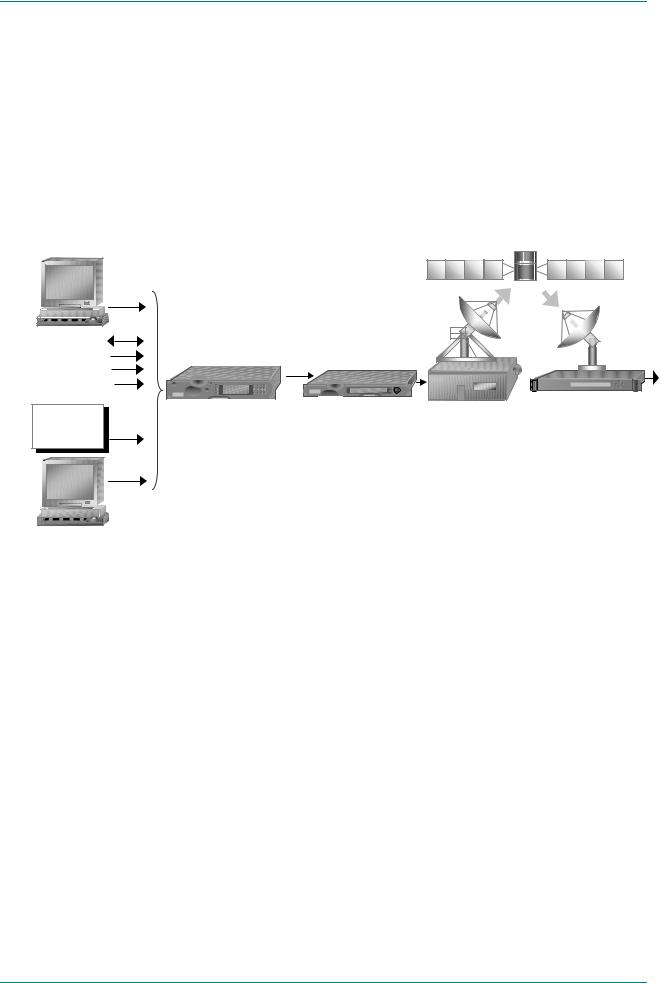
The Decoder is a component of TANDBERG Television’s range of equipment. It is designed for use by broadcasters and distributors of video and audio services. It can be used as a transport stream monitor or to decode signals received over a telecommunications network.
evolution 5000 Encoder (1)
1 |
2 |
3 |
4 |
5 |
6 |
7 |
8 |
9 |
0 |
* |
|
Ethernet
evolution 5000
Encoder (2)
Local |
0 |
* |
|
|
1 |
2 |
3 |
|
4 |
5 |
6 |
|
7 |
8 |
9 |
Inputs |
|
|
|
Ethernet
evolution 5000
Encoder (n)
1 |
2 |
3 |
4 |
5 |
6 |
7 |
8 |
9 |
0 |
* |
|
Ethernet
Transport Stream |
Processor |
evolution 5000 |
evolution 5000 |
Multiplexer (Main) |
Modulator (Main) |
1 2 3
4 |
5 |
6 |
7 |
8 |
9 |
0 |
* |
|
|
|
|
|
|
|
|
|
|
|
|
|
|
|
|
|
|
|
|
|
|
|
|
|
|
|
|
|
|
|
|
|
|
|
|
|
|
|
|
|
|
|
|
|
|
|
|
|
Ethernet |
Ethernet |
||||||
|
Control |
Control |
|||||
Network
Adapter Unit
evolution 5000 |
evolution 5000 |
|
Multiplexer (Standby) |
||
Modulator (Standby) |
||
|
1 |
2 |
3 |
4 |
5 |
6 |
7 |
8 |
9 |
0 |
* |
|
|
|
|
|
|
|
|
|
|
|
|
|
|
|
|
|
|
|
|
|
Ethernet |
Ethernet |
|
|
|
|||||
|
|
Network |
|||||||
Control |
Control |
|
|
||||||
|
Adapter Unit |
||||||||
|
|
|
|
|
|
|
|
||
MPEG-2 |
10BaseT |
|
Transport |
Ethernet |
|
Control |
||
Stream |
||
Ethernet Hub |
||
|
||
|
evolution 5000 |
|
|
Multiplex Element Manager |
Telecommunications
Network
TANDBERG |
TT1260 Decoder
Figure 1.6: Typical Compression System
Instruction Manual: TT1260 Standard Definition Professional Receiver/Decoder |
Page 1-13 |
ST.TM.E10100.1 |
|
Introduction
1.4.2Input Connections
The Decoder has the following inputs:
Two ASI copper interfaces for operation up to 160 Mbit/s for 188 byte packets and 160 Mbit/s for 204 byte packets.
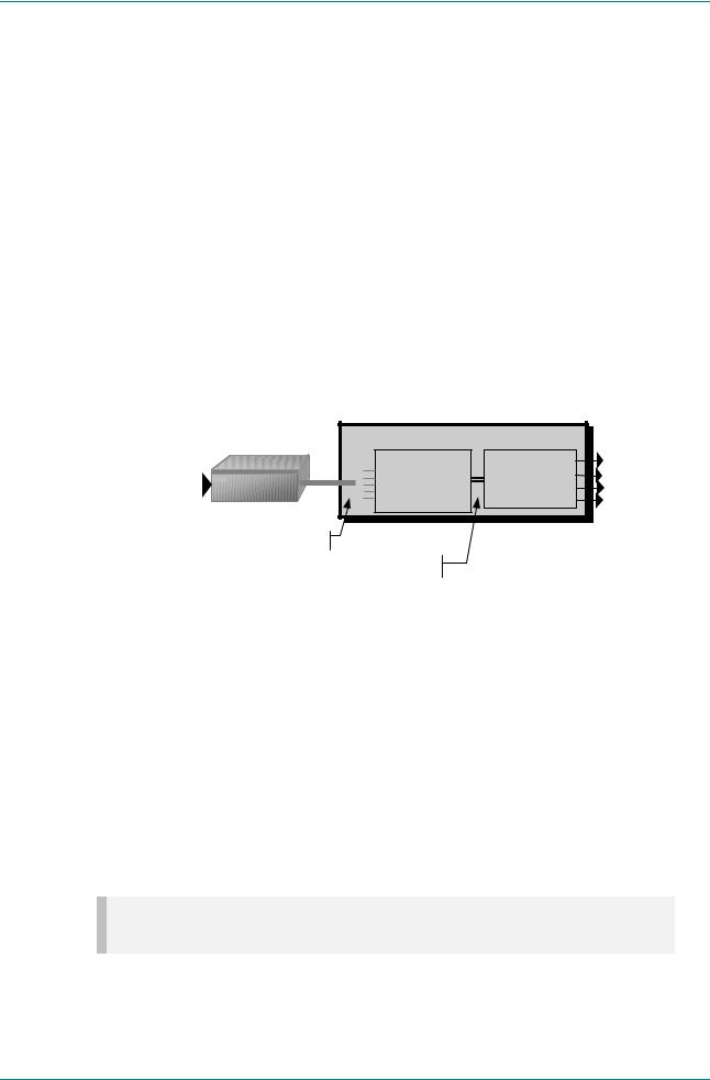
1.4.3What the Decoder Does
The ASI interfaces are used to present the transport stream in the format required by the internal Decoder circuitry. At this point, the operation of the unit is the same as the Satellite Receiver.
The Decoder can be used to receive an input signal from a Public Telecom Network via a Network Adapter Unit (NAU). No error correction is supported at the input of the unit so a level of Quality of Service should be negotiated with the Telecom Network Provider.
The Decoder is configured to select a single video service and other audio/data components from the multiple services on the incoming transport stream and present them at the output.
Network
Adapter Unit
Incoming Transport Stream carried over a 
telecommunications network
TT1260 Decoder |
|
|
Select a service |
Select the |
Video |
from the incoming |
components from |
Audio |
transport stream |
the selected |
Data |
|
i |
Transport Stream |
Multiple services on the incoming transport stream
Multiple components on the selected service
Figure 1.7: Role of the Decoder
1.5TT1260 Control Modes
1.5.1Introduction
The TT1260 is designed for unattended operation. Once set-up, the unit requires no further attention except to ensure the fan is working. There are up to three control modes associated with the Receiver (dependent upon options fitted). The unit remains in the chosen control mode until another mode is requested.
NOTE…
Local (Front Panel) Control is the factory default if TANDBERG Director is not installed.
Page 1-14 |
Instruction Manual: TT1260 Standard Definition Professional Receiver/Decoder |
|
ST.TM.E10100.1 |

Introduction
1.5.2Front Panel (Local) Modes
Operating the IRD from the Front Panel is via two main operating modes:
Navigate and Edit. See Section 3.3, Front Panel Operating Modes.
Timeout (5 minutes)
EDIT Off
EDIT |
NAVIGATE |
EDIT On
SAVE
Figure 1.8: Front Panel States
1.5.3Serial Remote Control Mode
The unit enters this state when the RS232/RS485 REMOTE port receives a configuration change command or the Remote control mode is selected in the System Menu (#6); see Section C.9, System Menu. During this state, local commands are ignored. When a modem is connected to the connector at the rear panel, it must be set to run at 9600 baud.
1.5.4TANDBERG Director NCP Control Mode
With the VideoGuard Conditional Access software installed and a valid Smart Card inserted, a TT1260 Satellite Receiver can be put into Director NCP control mode.
NOTE…
Front Panel mode is the factory default for Receivers used in a TANDBERG Director system. To switch to Director NCP mode refer to Section 3.8, Setting Up a System.
All Front Panel and Serial Remote commands are ignored except the operating mode. The TT1260 can be put into a local lockout condition. When in this condition, there are two ways to recover control:
Cancelling the local lockout using an over-air command.
Entering a PIN number via the Conditional Access menu in Menu #4.3.6 (see Section C.7.3, Director Menu).
Either of these actions will put the Receiver out of local lockout mode.
Instruction Manual: TT1260 Standard Definition Professional Receiver/Decoder |
Page 1-15 |
ST.TM.E10100.1 |
|

Introduction
1.6Guided Tour
1.6.1Construction
The TT1260 is constructed using a screened self-ventilated modular system; all operational inputs and outputs are via rear-panel connectors. The unit may be operated freestanding or mounted in a 19-inch rack.
1.6.2Front Panel Controls
The physical interface for the Front Panel consists of an alphanumeric LCD display, pushbuttons, and status LEDs that are used to set up and monitor the unit. The general layout is shown in Figure 1.9. Information on the use of these controls is given in Chapter 3, Operating the Equipment Locally.
User input is via six pushbuttons comprising four cursor pushbuttons: LEFT, RIGHT, UP, and DOWN; and two edit control pushbuttons: EDIT and SAVE.
Each pushbutton has an integral green LED except SAVE, which has an integral red LED. When lit these LEDs indicate to the user which pushbutton is currently active.
Automatic repeat following an initial delay period is implemented for the LEFT, RIGHT, UP and DOWN pushbuttons in software.
Alarm LED |
LCD display |
Edit Left Up |
|
|
|
|
|
|
Lock LED |
Save |
|
|
Right |
|
Down |
|||||
Figure 1.9: Front Panel Controls
1.6.3Front Panel LEDs
Figure 1.9 shows the location of the LEDs on the front panel. The LEDs indicate the equipment status as follows:
The red ALARM LED is used to indicate an IRD fault condition, e.g. a missing or faulty input signal. It should be off for correct operation, although it may be lit briefly during power-up.
The green LOCK LED is used to indicate that the IRD is locked to a transport stream when lit, and indicates correct conditions and correct system functioning.
1.6.4Bit Error Ratio Measurement
Bit Error Ratio (BER) measurement is done by an LCD display representation. See the QPSK Satellite menu (Section C.5, Input Status Menu).
Page 1-16 |
Instruction Manual: TT1260 Standard Definition Professional Receiver/Decoder |
|
ST.TM.E10100.1 |

Introduction
1.6.5Conditional Access and Scrambling Options
VideoGuard Director
There is a slot on the rear panel to allow the insertion of a Conditional Access (CA) card for the VideoGuard Director CA system.
Remote Authorisation System (RAS 1)
With the appropriate configuration, the TT1260 fully descrambles Remote Authorisation System (RAS) input transport stream. The ability to decrypt all the components in any other transport stream is a function of the specific CA system decryption.
Basic Interoperable Scrambling System (BISS)
With the appropriate configuration, the TT1260 fully descrambles the BISS mode-1 or mode-E input transport stream. This system has been developed by the European Broadcasting Union (EBU) as an open scrambling system.
BISS has five main levels of operation: Mode 0, Mode 1, Mode 2, Mode 3 and Mode-E
BISS Mode 0 corresponds to no scrambling.
BISS Mode 1 operation uses a fixed value for the control word to scramble the services in the transport stream from the Encoder. To descramble the transmission, the TT1260 needs to have the matching control word value.
BISS Mode E operation uses a fixed value for the control word to scramble the services in the transport stream from the Encoder. To descramble the transmission, the TT1260 needs to have the matching control word value.
BISS Modes 2 and 3 are not supported at this release.
1.6.6Rear Panel
Inputs and outputs to the unit are taken via the rear panel. Figure 1.10 shows a typical Decoder rear panel.
Figure 1.10: TT1260 Decoder Rear Panel
Connector descriptions are given in Chapter 2, Installing the Equipment and Chapter 5, Options.
Instruction Manual: TT1260 Standard Definition Professional Receiver/Decoder |
Page 1-17 |
ST.TM.E10100.1 |
|

Introduction
BLANK
Page 1-18 |
Instruction Manual: TT1260 Standard Definition Professional Receiver/Decoder |
|
ST.TM.E10100.1 |

Chapter 2
Installing the Equipment
Contents
2.1 |
Read This First!......................................................... |
2-3 |
|
|
2.1.1 |
Handling........................................................ |
2-3 |
|
2.1.2 |
Installing the Equipment ............................... |
2-3 |
|
2.1.3 |
Lifting ............................................................ |
2-3 |
2.2 |
Preliminary Checks ................................................... |
2-3 |
|
|
2.2.1 |
Mechanical Inspection .................................. |
2-3 |
|
2.2.2 Moving the Equipment Safely ....................... |
2-3 |
|
2.3 |
Installing the Equipment............................................ |
2-4 |
|
|
2.3.1 |
Fixing ............................................................ |
2-4 |
|
2.3.2 |
Ventilation..................................................... |
2-4 |
|
|
Openings in the Covers ................................ |
2-4 |
|
|
Care in Positioning........................................ |
2-4 |
|
|
Protection from Moisture............................... |
2-5 |
|
2.3.3 |
Installing Cables - Safety .............................. |
2-5 |
2.4 |
EMC Compliance Statements ................................... |
2-5 |
|
|
2.4.1 |
EN 55022/AS/NZS 3548............................... |
2-5 |
|
2.4.2 |
FCC .............................................................. |
2-5 |
2.5 |
AC Supply Operating Voltage and Fusing - Safety |
|
|
|
Information ................................................................ |
2-5 |
|
|
2.5.1 |
AC Power Supply.......................................... |
2-5 |
|
2.5.2 AC Power Supply Cord................................. |
2-6 |
|
|
|
General......................................................... |
2-6 |
|
|
Wire Colours................................................. |
2-6 |
|
2.5.3 Connecting the Equipment to the AC |
|
|
|
|
Power Supply................................................ |
2-7 |
2.6 |
Technical Earth Connection ...................................... |
2-7 |
|
2.7 |
Signal Connections ................................................... |
2-8 |
|
|
2.7.1 |
General......................................................... |
2-8 |
|
2.7.2 TT1260 Base Unit (TT1260/DIRBAS)......... |
2-10 |
|
|
|
Rear Panel View ......................................... |
2-10 |
ASI Out........................................................ |
2-10 |
Audio Outputs ............................................. |
2-10 |
Analogue Video Output ............................... |
2-11 |
Digital Video Output .................................... |
2-11 |
Frame Synchronisation ............................... |
2-12 |
Ethernet....................................................... |
2-12 |
Remote Control........................................... |
2-13 |
Alarm Connector and Relay ........................ |
2-13 |
RS-232 Low-speed Asynchronous Data |
|
Output ......................................................... |
2-14 |
2.7.3 Alarm Relay Card (TT1260/HDC/ALRM) .... |
2-14 |
General ....................................................... |
2-14 |
Rear Panel View ......................................... |
2-14 |
Connector Details........................................ |
2-15 |
Alarm Option ............................................... |
2-15 |
2.8 Option Card Connectors.......................................... |
2-16 |
Instruction Manual: TT1260 Standard Definition Professional Receiver/Decoder |
Page 2-1 |
ST.TM.E10100.1 |
|

Installing the Equipment
List of Figures
Figure 2.1: Air flow Through the Equipment................................... |
2-4 |
Figure 2.2: AC Power Inlet Assembly............................................. |
2-6 |
Figure 2.3: Location of the Technical Earth.................................... |
2-8 |
Figure 2.4: Typical Decoder Rear Panel ........................................ |
2-8 |
Figure 2.5: TT1260 Signal Connections......................................... |
2-9 |
Figure 2.6: Typical Decoder Rear Panel, with ASI Input and |
|
Alarm Option Fitted ..................................................... |
2-10 |
Figure 2.7: Alarm Relay Card Rear Panel .................................... |
2-14 |
List of Tables
Table 2.1: Fuse Information........................................................... |
2-6 |
Table 2.2: Supply Cord Wiring Colours ......................................... |
2-7 |
Table 2.3: Non Standard Supply Cord Wire Colours..................... |
2-7 |
Table 2.4: ASI Out Connector (2 Off) .......................................... |
2-10 |
Table 2.5: Audio Decoding Pin-outs............................................ |
2-11 |
Table 2.6: Analogue Output Connector (2 Off)............................ |
2-11 |
Table 2.7: Digital Output Connector (2 Off)................................. |
2-11 |
Table 2.8: Frame Sync Hi-Z Connector....................................... |
2-12 |
Table 2.9: Ethernet Pin-outs........................................................ |
2-12 |
Table 2.10: Remote Control Connector....................................... |
2-13 |
Table 2.11: Alarm Connector....................................................... |
2-13 |
Table 2.12: RS-232 Low-speed Data Connector......................... |
2-14 |
Table 2.13: Relay Alarm Output Specification............................. |
2-15 |
Page 2-2 |
Instruction Manual: TT1260 Standard Definition Professional Receiver/Decoder |
|
ST.TM.E10100.1 |

Installing the Equipment
2.1Read This First!
2.1.1Handling
The TT1260 must be handled and installed carefully and thoughtfully to prevent safety hazards and damage.
2.1.2Installing the Equipment
Ensure the personnel designated to fit the unit have the appropriate skills and knowledge. If in any doubt, contact TANDBERG Television Customer Services (see Preliminary Pages for contact details).
Installation of the product should follow these instructions, and should only use installation accessories recommended by the manufacturers. When rack mounted, this equipment must have shelf supports as well as being fixed at the front panel.
Do not use this product as a support for any other equipment.
2.1.3Lifting
Although this product only weighs approximately 4 kg (8.8 lb), in some circumstances it might be awkward to lift. In which case, do not attempt to lift or move it without proper assistance or equipment. If in doubt, seek assistance.
2.2Preliminary Checks
2.2.1Mechanical Inspection
WARNING…
REMOVING THE COVERS OF THIS EQUIPMENT MAY INVALIDATE ANY WARRANTIES, CAUSE A SAFETY HAZARD OR/AND AFFECT THE EMC PERFORMANCE. CHECK WITH TANDBERG TELEVISION CUSTOMER SERVICES.
Inspect the equipment for damage-in-transit. If in doubt, please contact TANDBERG Television Customer Services (see Preliminary Pages).
2.2.2Moving the Equipment Safely
Do not place this product on an unstable cart, stand, bracket, or table. The product may fall, causing serious injury and serious damage to the product. Use only with a cart, stand, bracket or table recommended by TANDBERG Television Ltd.
An appliance and cart combination should be moved with care. Quick stops, excessive force, and uneven surfaces may cause the appliance and cart combination to overturn. Do not move or carry the equipment whilst it is still connected to the supply or other leads, is live, or is in operation.
Instruction Manual: TT1260 Standard Definition Professional Receiver/Decoder |
Page 2-3 |
ST.TM.E10100.1 |
|
Installing the Equipment
2.3Installing the Equipment
2.3.1Fixing
The TT1260 is designed for fixed use only and has been shipped with fixing brackets suitable for a standard 19 inch rack. When installed in a rack, it should be secured using the fixing brackets. In addition, support shelves must be used to reduce the weight on the brackets. Ensure it is firmly and safely located and it has an adequate flow of free-air.
A freestanding unit should be installed on a secure horizontal surface where it is unlikely to be knocked or its connectors and leads disturbed.
2.3.2Ventilation
Openings in the Covers
Side openings in the cabinet, as well as a front-mounted cooling fan, are provided for ventilation. They ensure reliable operation of the product and protect it from overheating. The openings or the fan must not be blocked or covered.
Air is released through vents at both sides of the unit.
Air is drawn into the interior by a front-mounted cooling fan.
Figure 2.1: Air flow Through the Equipment
Care in Positioning
CAUTIONS...
1.The fan contained within this unit is not fitted with a dust/insect filter. Pay attention to the environment in which it is to be used.
2.Do not install units so that the air intake of one aligns with the outlet on another. Provide baffles and adequate spacing.
The TT1260 should never be placed near or over a radiator or other source of heat. It should not be placed in a built-in installation such as a rack unless proper ventilation is provided and the instructions have been adhered to.
Allow at least 40 mm free air-space at each side of the equipment to ensure adequate cooling. Racks containing stacked equipment may need to be forced air-cooled to reduce the ambient temperature within the rack.
Page 2-4 |
Instruction Manual: TT1260 Standard Definition Professional Receiver/Decoder |
|
ST.TM.E10100.1 |
 Loading...