


RETURN TO MAIN MENU |
IM917-A |
|
POWER WAVE®405M |
||
June, 2009 |
For use with machines Code 11379, 11491
Safety Depends on You
Lincoln arc welding and cutting equipment is designed and built with safety in mind. However, your overall safety can be increased by proper installation ... and thoughtful operation on your part. DO NOT INSTALL, OPERATE OR REPAIR THIS EQUIPMENT WITHOUT READING THIS MANUAL AND THE SAFETY PRECAUTIONS CONTAINED THROUGHOUT. And, most importantly, think before you act and be careful.
! |
W |
|
|
|
! |
|
|
||
W |
|
A |
|
|
|
R |
NI |
|
|
A |
R |
|
|
|
|
NI |
N |
G |
|
|
|
N |
G |
|
! |
AT |
|
|
|
||
! |
|
|
|
|
||
P AV |
IS |
TE |
|
|
||
R |
E |
O |
N |
TI |
||
|
|
CA |
DE |
ON |
||
|
|
|
UCI |
|
||
|
|
|
|
O |
N |
|
|
|
|
|
4 |
0 |
5 |
|
|
|
|
|
|
|
|
|
A |
V |
E |
|
|
|
|
|
|
|
||
|
|
W |
|
|
|
|
|
O |
WER |
|
|
|
|
P |
|
|
|
|
|
|
|
|
|
|
|
|
OPERATOR’S MANUAL
Copyright © Lincoln Global Inc.
•World's Leader in Welding and Cutting Products •
•Sales and Service through Subsidiaries and Distributors Worldwide •
Cleveland, Ohio 44117-1199 U.S.A. TEL: 216.481.8100 FAX: 216.486.1751 WEB SITE: www.lincolnelectric.com
i
SAFETY
i
 WARNING
CALIFORNIA PROPOSITION 65 WARNINGS
Diesel engine exhaust and some of its constituents are known to the State of California to cause cancer, birth defects, and other reproductive harm.
The Above For Diesel Engines
The engine exhaust from this product contains chemicals known to the State of California to cause cancer, birth defects, or other reproductive harm.
The Above For Gasoline Engines
ARC WELDING CAN BE HAZARDOUS. PROTECT YOURSELF AND OTHERS FROM POSSIBLE SERIOUS INJURY OR DEATH. KEEP CHILDREN AWAY. PACEMAKER WEARERS SHOULD CONSULT WITH THEIR DOCTOR BEFORE OPERATING.
Read and understand the following safety highlights. For additional safety information, it is strongly recommended that you purchase a copy of “Safety in Welding & Cutting - ANSI Standard Z49.1” from the American Welding Society, P.O. Box 351040, Miami, Florida 33135 or CSA Standard W117.2-1974. A Free copy of “Arc Welding Safety” booklet E205 is available from the Lincoln Electric Company, 22801 St. Clair Avenue, Cleveland, Ohio 44117-1199.
BE SURE THAT ALL INSTALLATION, OPERATION, MAINTENANCE AND REPAIR PROCEDURES ARE PERFORMED ONLY BY QUALIFIED INDIVIDUALS.
FOR ENGINE powered equipment.
1.a. Turn the engine off before troubleshooting and maintenance work unless the maintenance work requires it to be running.
____________________________________________________
1.b. Operate engines in open, well-ventilated areas or vent the engine exhaust fumes outdoors.
____________________________________________________
1.c. Do not add the fuel near an open flame welding arc or when the engine is running.
Stop the engine and allow it to cool before refueling to prevent spilled fuel from vaporizing on contact with hot engine parts and igniting. Do not spill fuel when filling tank. If fuel is spilled, wipe it up and do not start engine until fumes have been eliminated.
____________________________________________________
1.d. Keep all equipment safety guards, covers and devices in position and in good repair.Keep hands, hair, clothing and tools away from V-belts, gears, fans and all other moving parts when starting, operating or repairing equipment.
____________________________________________________
1.e. In some cases it may be necessary to remove safety guards to perform required maintenance. Remove guards only when necessary and replace them when the maintenance requiring their removal is complete. Always use the greatest care when working near moving parts.
___________________________________________________
1.f. Do not put your hands near the engine fan. Do not attempt to override the governor or idler by pushing on the throttle control rods
while the engine is running.
___________________________________________________
1.g. To prevent accidentally starting gasoline engines while turning the engine or welding generator during maintenance work, disconnect the spark plug wires, distributor cap or magneto wire as appropriate.
1.h. To avoid scalding, do not remove the radiator pressure cap when the engine is hot.
ELECTRIC AND MAGNETIC FIELDS may be dangerous
2.a. Electric current flowing through any conductor causes localized Electric and Magnetic Fields (EMF). Welding current creates EMF fields around welding cables and welding machines
2.b. EMF fields may interfere with some pacemakers, and welders having a pacemaker should consult their physician before welding.
2.c. Exposure to EMF fields in welding may have other health effects which are now not known.
2.d. All welders should use the following procedures in order to minimize exposure to EMF fields from the welding circuit:
2.d.1. Route the electrode and work cables together - Secure them with tape when possible.
2.d.2. Never coil the electrode lead around your body.
2.d.3. Do not place your body between the electrode and work cables. If the electrode cable is on your right side, the work cable should also be on your right side.
2.d.4. Connect the work cable to the workpiece as close as possible to the area being welded.
2.d.5. Do not work next to welding power source.
Mar ‘95
ii |
|
SAFETY |
|
ii |
|
|
|
|
|
|
|
|
|
|
ELECTRIC SHOCK can
kill.
3.a. The electrode and work (or ground) circuits are electrically “hot” when the welder is on. Do not touch these “hot” parts with your bare skin or wet clothing. Wear dry, hole-free
gloves to insulate hands.
3.b. Insulate yourself from work and ground using dry insulation. Make certain the insulation is large enough to cover your full area of physical contact with work and ground.
In addition to the normal safety precautions, if welding must be performed under electrically hazardous conditions (in damp locations or while wearing wet clothing; on metal structures such as floors, gratings or scaffolds; when in cramped positions such as sitting, kneeling or lying, if there is a high risk of unavoidable or accidental contact with the workpiece or ground) use the following equipment:
•Semiautomatic DC Constant Voltage (Wire) Welder.
•DC Manual (Stick) Welder.
•AC Welder with Reduced Voltage Control.
3.c. In semiautomatic or automatic wire welding, the electrode, electrode reel, welding head, nozzle or semiautomatic welding gun are also electrically “hot”.
3.d. Always be sure the work cable makes a good electrical connection with the metal being welded. The connection should be as close as possible to the area being welded.
3.e. Ground the work or metal to be welded to a good electrical (earth) ground.
3.f. Maintain the electrode holder, work clamp, welding cable and welding machine in good, safe operating condition. Replace damaged insulation.
3.g. Never dip the electrode in water for cooling.
3.h. Never simultaneously touch electrically “hot” parts of electrode holders connected to two welders because voltage between the two can be the total of the open circuit voltage of both welders.
3.i. When working above floor level, use a safety belt to protect yourself from a fall should you get a shock.
3.j. Also see Items 6.c. and 8.
ARC RAYS can burn.
4.a. Use a shield with the proper filter and cover plates to protect your eyes from sparks and the rays of the arc when welding or observing open arc welding. Headshield and filter lens should conform to ANSI Z87. I standards.
4.b. Use suitable clothing made from durable flame-resistant material to protect your skin and that of your helpers from the arc rays.
4.c. Protect other nearby personnel with suitable, non-flammable screening and/or warn them not to watch the arc nor expose themselves to the arc rays or to hot spatter or metal.
FUMES AND GASES
can be dangerous.
5.a. Welding may produce fumes and gases
hazardous to health. Avoid breathing these fumes and gases. When welding, keep your head out of the fume. Use enough ventilation and/or exhaust at the arc to keep
fumes and gases away from the breathing zone. When welding with electrodes which require special ventilation such as stainless or hard facing (see instructions on container or MSDS) or on lead or cadmium plated steel and other metals or coatings which produce highly toxic fumes, keep exposure as low as possible and within applicable OSHA PEL and ACGIH TLV limits using local exhaust or mechanical ventilation. In confined spaces or in some circumstances, outdoors, a respirator may be required. Additional precautions are also required when welding on galvanized steel.
5.b. The operation of welding fume control equipment is affected by various factors including proper use and positioning of the equipment, maintenance of the equipment and the specific welding procedure and application involved. Worker exposure level should be checked upon installation and periodically thereafter to be certain it is within applicable OSHA PEL and ACGIH TLV limits.
5.c. Do not weld in locations near chlorinated hydrocarbon vapors coming from degreasing, cleaning or spraying operations. The heat and rays of the arc can react with solvent vapors to form phosgene, a highly toxic gas, and other irritating products.
5.d. Shielding gases used for arc welding can displace air and cause injury or death. Always use enough ventilation, especially in confined areas, to insure breathing air is safe.
5.e. Read and understand the manufacturer’s instructions for this equipment and the consumables to be used, including the material safety data sheet (MSDS) and follow your employer’s safety practices. MSDS forms are available from your welding distributor or from the manufacturer.
5.f. Also see item 1.b.
Jan ‘09
iii
SAFETY
iii


 WELDING and CUTTING

 SPARKS can
cause fire or explosion.
6.a. Remove fire hazards from the welding area. If this is not possible, cover them to prevent the welding sparks from starting a fire.
Remember that welding sparks and hot materials from welding can easily go through small cracks and openings to adjacent areas. Avoid welding near hydraulic lines. Have a fire extinguisher readily available.
6.b. Where compressed gases are to be used at the job site, special precautions should be used to prevent hazardous situations. Refer to “Safety in Welding and Cutting” (ANSI Standard Z49.1) and the operating information for the equipment being used.
6.c. When not welding, make certain no part of the electrode circuit is touching the work or ground. Accidental contact can cause overheating and create a fire hazard.
6.d. Do not heat, cut or weld tanks, drums or containers until the proper steps have been taken to insure that such procedures will not cause flammable or toxic vapors from substances inside. They can cause an explosion even though they have been “cleaned”. For information, purchase “Recommended Safe Practices for the Preparation for Welding and Cutting of Containers and Piping That Have Held Hazardous
Substances”, AWS F4.1 from the American Welding Society
(see address above).
6.e. Vent hollow castings or containers before heating, cutting or welding. They may explode.
6.f. Sparks and spatter are thrown from the welding arc. Wear oil free protective garments such as leather gloves, heavy shirt, cuffless trousers, high shoes and a cap over your hair. Wear ear plugs when welding out of position or in confined places. Always wear safety glasses with side shields when in a welding area.
6.g. Connect the work cable to the work as close to the welding area as practical. Work cables connected to the building framework or other locations away from the welding area increase the possibility of the welding current passing through lifting chains, crane cables or other alternate circuits. This can create fire hazards or overheat lifting chains or cables until they fail.
6.h. Also see item 1.c.
6.I. Read and follow NFPA 51B “ Standard for Fire Prevention During Welding, Cutting and Other Hot Work”, available from NFPA, 1 Batterymarch Park, PO box 9101, Quincy, Ma 022690-9101.
6.j. Do not use a welding power source for pipe thawing.
CYLINDER may explode


 if damaged.
7.a. Use only compressed gas cylinders
containing the correct shielding gas for the process used and properly operating regulators designed for the gas and
pressure used. All hoses, fittings, etc. should be suitable for the application and maintained in good condition.
7.b. Always keep cylinders in an upright position securely chained to an undercarriage or fixed support.
7.c. Cylinders should be located:
•Away from areas where they may be struck or subjected to physical damage.
•A safe distance from arc welding or cutting operations and any other source of heat, sparks, or flame.
7.d. Never allow the electrode, electrode holder or any other electrically “hot” parts to touch a cylinder.
7.e. Keep your head and face away from the cylinder valve outlet when opening the cylinder valve.
7.f. Valve protection caps should always be in place and hand tight except when the cylinder is in use or connected for use.
7.g. Read and follow the instructions on compressed gas cylinders, associated equipment, and CGA publication P-l,
“Precautions for Safe Handling of Compressed Gases in Cylinders,” available from the Compressed Gas Association 1235 Jefferson Davis Highway, Arlington, VA 22202.
FOR ELECTRICALLY powered equipment.
8.a. Turn off input power using the disconnect switch at the fuse box before working on the equipment.
8.b. Install equipment in accordance with the U.S. National Electrical Code, all local codes and the manufacturer’s recommendations.
8.c. Ground the equipment in accordance with the U.S. National
Electrical Code and the manufacturer’s recommendations.
Refer to http://www.lincolnelectric.com/safety for additional safety information.
Jan ‘09

iv
SAFETY
iv
PRÉCAUTIONS DE SÛRETÉ
Pour votre propre protection lire et observer toutes les instructions et les précautions de sûreté specifiques qui parraissent dans ce manuel aussi bien que les précautions de sûreté générales suivantes:
Sûreté Pour Soudage A L’Arc
1.Protegez-vous contre la secousse électrique:
a.Les circuits à l’électrode et à la piéce sont sous tension quand la machine à souder est en marche. Eviter toujours tout contact entre les parties sous tension et la peau nue ou les vétements mouillés. Porter des gants secs et sans trous pour isoler les mains.
b.Faire trés attention de bien s’isoler de la masse quand on soude dans des endroits humides, ou sur un plancher metallique ou des grilles metalliques, principalement dans les positions assis ou couché pour lesquelles une grande partie du corps peut être en contact avec la masse.
c.Maintenir le porte-électrode, la pince de masse, le câble de soudage et la machine à souder en bon et sûr état defonctionnement.
d.Ne jamais plonger le porte-électrode dans l’eau pour le refroidir.
e.Ne jamais toucher simultanément les parties sous tension des porte-électrodes connectés à deux machines à souder parce que la tension entre les deux pinces peut être le total de la tension à vide des deux machines.
f.Si on utilise la machine à souder comme une source de courant pour soudage semi-automatique, ces precautions pour le porte-électrode s’applicuent aussi au pistolet de soudage.
2.Dans le cas de travail au dessus du niveau du sol, se protéger contre les chutes dans le cas ou on recoit un choc. Ne jamais enrouler le câble-électrode autour de n’importe quelle partie du corps.
3.Un coup d’arc peut être plus sévère qu’un coup de soliel, donc:
a.Utiliser un bon masque avec un verre filtrant approprié ainsi qu’un verre blanc afin de se protéger les yeux du rayonnement de l’arc et des projections quand on soude ou quand on regarde l’arc.
b.Porter des vêtements convenables afin de protéger la peau de soudeur et des aides contre le rayonnement de l‘arc.
c.Protéger l’autre personnel travaillant à proximité au soudage à l’aide d’écrans appropriés et non-inflammables.
4.Des gouttes de laitier en fusion sont émises de l’arc de soudage. Se protéger avec des vêtements de protection libres de l’huile, tels que les gants en cuir, chemise épaisse, pantalons sans revers, et chaussures montantes.
5.Toujours porter des lunettes de sécurité dans la zone de soudage. Utiliser des lunettes avec écrans lateraux dans les zones où l’on pique le laitier.
6.Eloigner les matériaux inflammables ou les recouvrir afin de prévenir tout risque d’incendie dû aux étincelles.
7.Quand on ne soude pas, poser la pince à une endroit isolé de la masse. Un court-circuit accidental peut provoquer un échauffement et un risque d’incendie.
8.S’assurer que la masse est connectée le plus prés possible de la zone de travail qu’il est pratique de le faire. Si on place la masse sur la charpente de la construction ou d’autres endroits éloignés de la zone de travail, on augmente le risque de voir passer le courant de soudage par les chaines de levage, câbles de grue, ou autres circuits. Cela peut provoquer des risques d’incendie ou d’echauffement des chaines et des câbles jusqu’à ce qu’ils se rompent.
9.Assurer une ventilation suffisante dans la zone de soudage. Ceci est particuliérement important pour le soudage de tôles galvanisées plombées, ou cadmiées ou tout autre métal qui produit des fumeés toxiques.
10.Ne pas souder en présence de vapeurs de chlore provenant d’opérations de dégraissage, nettoyage ou pistolage. La chaleur ou les rayons de l’arc peuvent réagir avec les vapeurs du solvant pour produire du phosgéne (gas fortement toxique) ou autres produits irritants.
11.Pour obtenir de plus amples renseignements sur la sûreté, voir le code “Code for safety in welding and cutting” CSA Standard W 117.2-1974.
PRÉCAUTIONS DE SÛRETÉ POUR LES MACHINES À SOUDER À TRANSFORMATEUR ET À REDRESSEUR
1.Relier à la terre le chassis du poste conformement au code de l’électricité et aux recommendations du fabricant. Le dispositif de montage ou la piece à souder doit être branché à une bonne mise à la terre.
2.Autant que possible, I’installation et l’entretien du poste seront effectués par un électricien qualifié.
3.Avant de faires des travaux à l’interieur de poste, la debrancher à l’interrupteur à la boite de fusibles.
4.Garder tous les couvercles et dispositifs de sûreté à leur place.
Mar. ‘93

v |
SAFETY |
v |
|
|
|
Electromagnetic Compatibility (EMC)
Conformance
Products displaying the CE mark are in conformity with European Community Council Directive of 3 May 1989 on the approximation of the laws of the Member States relating to electromagnetic compatibility (89/336/EEC). It was manufactured in conformity with a national standard that implements a harmonized standard: EN 60974-10 Electromagnetic Compatibility (EMC) Product Standard for Arc Welding Equipment. It is for use with other Lincoln Electric equipment. It is designed for industrial and professional use.
Introduction
All electrical equipment generates small amounts of electromagnetic emission. Electrical emission may be transmitted through power lines or radiated through space, similar to a radio transmitter. When emissions are received by other equipment, electrical interference may result. Electrical emissions may affect many kinds of electrical equipment; other nearby welding equipment, radio and TV reception, numerical controlled machines, telephone systems, computers, etc. Be aware that interference may result and extra precautions may be required when a welding power source is used in a domestic establishment.
Installation and Use
The user is responsible for installing and using the welding equipment according to the manufacturer’s instructions. If electromagnetic disturbances are detected then it shall be the responsibility of the user of the welding equipment to resolve the situation with the technical assistance of the manufacturer. In some cases this remedial action may be as simple as earthing (grounding) the welding circuit, see Note. In other cases it could involve construction of an electromagnetic screen enclosing the power source and the work complete with associated input filters. In all cases electromagnetic disturbances must be reduced to the point where they are no longer troublesome.
Note: The welding circuit may or may not be earthed for safety reasons according to national codes. Changing the earthing arrangements should only be authorized by a person who is competent to access whether the changes will increase the risk of injury, e.g., by allowing parallel welding current return paths which may damage the earth circuits of other equipment.
Assessment of Area
Before installing welding equipment the user shall make an assessment of potential electromagnetic problems in the surrounding area. The following shall be taken into account:
a)other supply cables, control cables, signaling and telephone cables; above, below and adjacent to the welding equipment;
b)radio and television transmitters and receivers;
c)computer and other control equipment;
d)safety critical equipment, e.g., guarding of industrial equipment;
e)the health of the people around, e.g., the use of pacemakers and hearing aids;
f)equipment used for calibration or measurement
g)the immunity of other equipment in the environment. The user shall ensure that other equipment being used in the environment is compatible. This may require additional protection measures;
h)the time of day that welding or other activities are to be carried out.
L10093 3-1-96H

vi |
SAFETY |
vi |
|
|
|
Electromagnetic Compatibility (EMC)
The size of the surrounding area to be considered will depend on the structure of the building and other activities that are taking place. The surrounding area may extend beyond the boundaries of the premises.
Methods of Reducing Emissions
Mains Supply
Welding equipment should be connected to the mains supply according to the manufacturer’s recommendations. If interference occurs, it may be necessary to take additional precautions such as filtering of the mains supply. Consideration should be given to shielding the supply cable of permanently installed welding equipment, in metallic conduit or equivalent. Shielding should be electrically continuous throughout its length. The shielding should be connected to the welding power source so that good electrical contact is maintained between the conduit and the welding power source enclosure.
Maintenance of the Welding Equipment
The welding equipment should be routinely maintained according to the manufacturer’s recommendations. All access and service doors and covers should be closed and properly fastened when the welding equipment is in operation. The welding equipment should not be modified in any way except for those changes and adjustments covered in the manufacturers instructions. In particular, the spark gaps of arc striking and stabilizing devices should be adjusted and maintained according to the manufacturer’s recommendations.
Welding Cables
The welding cables should be kept as short as possible and should be positioned close together, running at or close to floor level.
Equipotential Bonding
Bonding of all metallic components in the welding installation and adjacent to it should be considered. However, metallic components bonded to the work piece will increase the risk that the operator could receive a shock by touching these metallic components and the electrode at the same time. The operator should be insulated from all such bonded metallic components.
Earthing of the Workpiece
Where the workpiece is not bonded to earth for electrical safety, not connected to earth because of its size and position, e.g., ships hull or building steelwork, a connection bonding the workpiece to earth may reduce emissions in some, but not all instances. Care should be taken to prevent the earthing of the workpiece increasing the risk of injury to users, or damage to other electrical equipment. Where necessary, the connection of the workpiece to earth should be made by a direct connection to the workpiece, but in some countries where direct connection is not permitted, the bonding should be achieved by suitable capacitance, selected according to national regulations.
Screening and Shielding
Selective screening and shielding of other cables and equipment in the surrounding area may alleviate problems of interference. Screening of the entire welding installation may be considered for special applications. 1
_________________________
1Portions of the preceding text are contained in EN 60974-10: “Electromagnetic Compatibility (EMC) product standard for arc welding equipment.”
L10093 3-1-96H

vii
Thank You
vii
for selecting a QUALITY product by Lincoln Electric. We want you to take pride in operating this Lincoln Electric Company product
••• as much pride as we have in bringing this product to you!
CUSTOMER ASSISTANCE POLICY
The business of The Lincoln Electric Company is manufacturing and selling high quality welding equipment, consumables, and cutting equipment. Our challenge is to meet the needs of our customers and to exceed their expectations. On occasion, purchasers may ask Lincoln Electric for advice or information about their use of our products. We respond to our customers based on the best information in our possession at that time. Lincoln Electric is not in a position to warrant or guarantee such advice, and assumes no liability, with respect to such information or advice. We expressly disclaim any warranty of any kind, including any warranty of fitness for any customer’s particular purpose, with respect to such information or advice. As a matter of practical consideration, we also cannot assume any responsibility for updating or correcting any such information or advice once it has been given, nor does the provision of information or advice create, expand or alter any warranty with respect to the sale of our products.
Lincoln Electric is a responsive manufacturer, but the selection and use of specific products sold by Lincoln Electric is solely within the control of, and remains the sole responsibility of the customer. Many variables beyond the control of Lincoln Electric affect the results obtained in applying these types of fabrication methods and service requirements.
Subject to Change – This information is accurate to the best of our knowledge at the time of printing. Please refer to www.lincolnelectric.com for any updated information.
Please Examine Carton and Equipment For Damage Immediately
When this equipment is shipped, title passes to the purchaser upon receipt by the carrier. Consequently, Claims for material damaged in shipment must be made by the purchaser against the transportation company at the time the shipment is received.
Please record your equipment identification information below for future reference. This information can be found on your machine nameplate.
Product _________________________________________________________________________________
Model Number ___________________________________________________________________________
Code Number or Date Code_________________________________________________________________
Serial Number____________________________________________________________________________
Date Purchased___________________________________________________________________________
Where Purchased_________________________________________________________________________
Whenever you request replacement parts or information on this equipment, always supply the information you have recorded above. The code number is especially important when identifying the correct replacement parts.
On-Line Product Registration
-Register your machine with Lincoln Electric either via fax or over the Internet.
•For faxing: Complete the form on the back of the warranty statement included in the literature packet
accompanying this machine and fax the form per the instructions printed on it.
• For On-Line Registration: Go to our WEB SITE at www.lincolnelectric.com. Choose “Quick Links” and then “Product Registration”. Please complete the form and submit your registration.
Read this Operators Manual completely before attempting to use this equipment. Save this manual and keep it handy for quick reference. Pay particular attention to the safety instructions we have provided for your protection. The level of seriousness to be applied to each is explained below:
 WARNING
This statement appears where the information must be followed exactly to avoid serious personal injury or loss of life.
 CAUTION
This statement appears where the information must be followed to avoid minor personal injury or damage to this equipment.
viii |
TABLE OF CONTENTS |
viii |
|
|
Page |
|
Installation ....................................................................................................... |
Section A |
|
Technical Specifications - POWER WAVE® 405M .............................................. |
A-1 |
|
Safety Precautions................................................................................................. |
A-2 |
|
Select Suitable Location ........................................................................................ |
A-2 |
|
Stacking .......................................................................................................... |
A-2 |
|
Tilting............................................................................................................... |
A-2 |
|
Input and Grounding Connections .................................................................. |
A-2 |
|
Power Cord Connection .................................................................................. |
A-2 |
|
Undercarriage Mountings................................................................................ |
A-2 |
|
Output Cables, Connections and Limitations......................................................... |
A-3 |
|
Negative Electrode Polarity ................................................................................... |
A-3 |
|
Voltage Sensing ................................................................................................... |
A-4 |
|
POWER WAVE® to Semi-automatic Power Feed Wire Feeder Interconnections A-5 |
|
|
System Description................................................................................................ |
A-5 |
|
System Set-Up............................................................................................... |
A-6, A-7 |
|
Welding with Multiple POWER WAVE®s .............................................................. |
A-8 |
|
Control Cable Specifications.................................................................................. |
A-8 |
|
Multiple Arc Unsynchronized sense and work leads ............................................. |
A-9 |
|
I / O Receptacle Specifications............................................................................ |
A-10 |
|
Dip Switch Settings and Locations............................................................... |
A-10 |
|
Control Board Dip Switch .............................................................................. |
A-10 |
|
________________________________________________________________________ |
|
|
Operation ......................................................................................................... |
Section B |
|
Safety Precautions................................................................................................. |
B-1 |
|
General Description............................................................................................... |
B-1 |
|
Recommended Processes and Equipment ........................................................... |
B-1 |
|
Recommended Processes .............................................................................. |
B-1 |
|
Required Equipment ....................................................................................... |
B-2 |
|
Limitations ....................................................................................................... |
B-2 |
|
Duty Cycle and Time Period ........................................................................... |
B-2 |
|
Case Front Controls ........................................................................................ |
B-2 |
|
Nominal Procedures........................................................................................ |
B-3 |
|
Fringe Procedures........................................................................................... |
B-3 |
|
Making a Weld ................................................................................................ |
B-3 |
|
Welding Adjustment ........................................................................................ |
B-3 |
|
Constant Voltage Welding............................................................................... |
B-4 |
|
Pulse Welding ................................................................................................. |
B-5 |
|
TIG GTAW, SMAW, and Arc Gouging ............................................................ |
B-6 |
|
Power Mode and Recommended Welding Procedures .................................. |
B-7 |
|
________________________________________________________________________ |
|
|
Accessories ..................................................................................................... |
Section C |
|
Optional Equipment............................................................................................... |
C-1 |
|
Factory Installed.............................................................................................. |
C-1 |
|
Field Installed.................................................................................................. |
C-1 |
|
Compatible Lincoln Equipment |
|
|
________________________________________________________________________ |
|
|
Maintenance .................................................................................................... |
Section D |
|
Safety Precautions ................................................................................................ |
D-1 |
|
Capacitor Discharge Procedure ............................................................................ |
D-1 |
|
Routine Maintenance............................................................................................. |
D-1 |
|
Periodic Maintenance............................................................................................ |
D-1 |
|
Calibration Specification........................................................................................ |
D-1 |
|
________________________________________________________________________ |
|
|
Troubleshooting .............................................................................................. |
Section E |
|
How to use Troubleshooting Guide ....................................................................... |
E-1 |
|
Using the Status LED to Troubleshoot System Problems ..................................... |
E-2 |
|
Troubleshooting Guide............................................................................. |
E-3 thru E-7 |
|
________________________________________________________________________ |
|
|
Wiring Diagram ............................................................................................ |
Section F-1 |
|
Connection Diagram .................................................................................... |
Section F-2 |
|
Dimension Print............................................................................................ |
Section F-3 |
|
________________________________________________________________________ |
|
|
Parts Lists............................................................................................................... |
P-551 |
|
________________________________________________________________________ |
|

|
A-1 |
|
|
|
|
|
|
|
|
|
INSTALLATION |
|
|
|
|
|
|
A-1 |
|
|||||
|
|
|
|
|
|
|
|
|
|
|
|
|
|
|
|
|
|
|
|
|
|
|
|
|
TECHNICAL SPECIFICATIONS - POWER WAVE® 405M |
|
|
|
|
|
|
|
|
||||||||||||||||
|
|
|
|
|
|
|
|
|
|
|
|
|
|
|
|
|
|
|
|
|
|
|||
|
|
|
|
|
|
|
|
INPUT AC VOLTAGE & DC OUTPUT |
|
|
|
|
||||||||||||
|
Product |
|
Ordering |
Input AC |
|
Rated DC Output |
|
|
Output |
|
Weight |
|
Dimensions |
|
||||||||||
|
Name |
Information |
Voltage |
|
Amps/Volts/Duty Cycle |
|
|
Range |
|
with Cord |
|
HxWxD |
|
|
||||||||||
|
|
|
|
|
|
|
|
50/60 Hz |
|
(continuous) |
|
|
|
|
|
|
|
|
|
|||||
|
|
|
|
|
|
|
|
|
|
|
|
|
|
|
|
|
|
|
|
|
|
|
||
|
|
|
|
|
|
|
|
350A / 34V / 60% |
|
|
|
|
|
|
|
|
14.7”x12.5”x |
|
||||||
|
Power |
|
|
200-220/ |
|
|
3 Phase |
|
|
|
|
|
|
|
|
27.8”* |
|
|
||||||
|
Wave |
|
K 2369-2 |
380-400/ |
320A / 33V / 60% |
|
|
AMPS |
|
86.5lbs |
|
(373x318x |
|
|||||||||||
|
405M |
|
|
415 |
|
|
1 Phase |
|
5-425 |
|
(37.4 kg) |
|
706*)mm |
|
||||||||||
|
|
|
|
|
50/60 Hz |
|
|
|
|
|
|
|
|
|
|
|
|
|
|
|
|
|
|
|
|
|
|
|
|
|
275A / 31V /100% |
|
|
|
|
|
|
|
|
|
|
|
|
|
|||||
|
|
|
|
|
|
|
|
|
|
|
|
|
|
|
|
|
|
|
|
|||||
|
|
|
|
|
|
|
|
1 Phase |
|
|
|
|
|
|
|
|
|
|
|
|
||||
|
|
|
|
|
|
|
|
300A / 32V / 100% |
|
|
|
|
|
|
|
|
* Includes |
|
|
|||||
|
|
|
|
|
|
|
|
3 Phase |
|
|
|
|
|
|
|
|
handles |
|
|
|||||
|
|
|
|
|
|
|
|
|
|
|
|
|
|
|
|
|
|
|
|
|
||||
|
* Overall Length Including Handle, 21.6” (549mm) without handle. |
|
|
|
|
|
|
|
|
|||||||||||||||
|
Insulation Class 180 (H) |
|
|
|
|
|
|
|
|
|
|
|
|
|
|
|
|
|
|
|||||
|
|
|
|
|
|
|
|
|
|
|
|
|
|
|
|
|||||||||
|
|
|
|
|
|
POWER WAVE® 405M INPUT CURRENT |
|
|
|
|
||||||||||||||
|
Recommended Fuse Sizes Based On The U.S. National Electrical Code And Maximum Machine Outputs |
|
||||||||||||||||||||||
|
Input 50/60 Hz |
|
|
|
Output |
|
Recommended |
|
|
Notes |
|
|||||||||||||
|
Voltage |
|
Phases |
|
300Amps@ |
|
|
350Amps@ |
|
Line Cord |
|
|
Size Fuse Size |
|
|
|||||||||
|
|
|
|
|
|
32Volts(100%) |
|
|
34Volts(60%) |
|
AWG SIZES |
|
|
|
|
|
||||||||
|
200 |
|
|
3 |
|
|
41 |
|
48 |
|
|
|
6 |
|
|
|
80A |
|
|
Note 2 |
|
|||
|
220 |
|
|
3 |
|
|
37 |
|
48 |
|
|
|
6 |
|
|
|
80A |
|
|
Note 2 |
|
|||
|
380 |
|
|
3 |
|
|
23 |
|
28 |
|
|
|
8 |
|
|
|
50A |
|
|
|
|
|||
|
400 |
|
|
3 |
|
|
22 |
|
27 |
|
|
|
8 |
|
|
|
50A |
|
|
|
|
|||
|
415 |
|
|
3 |
|
|
22 |
|
26 |
|
|
|
8 |
|
|
|
50A |
|
|
|
|
|||
|
|
|
|
|
|
|
|
|
|
|
|
|
|
|
|
|
||||||||
|
Voltage |
|
Phases |
|
275Amps@ |
|
|
320Amps@ |
|
Line Cord |
|
|
Size Fuse Size |
|
Notes |
|
||||||||
|
|
|
|
|
|
31Volts(100%) |
|
33Volts(60%) |
|
|
|
|
|
|
|
|
|
|
|
|||||
200 |
|
|
1 |
|
|
---- |
|
|
---- |
|
|
|
--- |
|
|
----- |
|
|
Note 1 |
|
||||
220 |
|
|
1 |
|
|
64 |
|
|
82 |
|
|
|
4 |
|
|
|
125A |
|
Note 2 |
|
||||
380 |
|
|
1 |
|
|
44 |
|
|
55 |
|
|
|
6 |
|
|
|
80A |
|
|
Note 2 |
|
|||
400 |
|
|
1 |
|
|
40 |
|
|
50 |
|
|
|
8 |
|
|
|
80A |
|
|
|
|
|||
415 |
|
|
1 |
|
|
38 |
|
|
48 |
|
|
|
8 |
|
|
|
80A |
|
|
|
|
|||
|
|
|
|
|
|
|
|
|
|
|
|
|
|
|
|
|
|
|
|
|
|
|
|
|
1.Not rated is indicated by 4-x's in the box on the rating plate
2.When operating on these inputs, the line cord should be changed to an input conductor of 6 AWG or larger.
OUTPUT CABLES, CONNECTIONS AND LIMITATIONS
Select the output cable size based upon the following chart.
Cable sizes for Combined Length of Electrode and Work Cable (Copper) 75°C rated:
|
DUTY CYCLE |
CURRENT |
LENGTH UP 61m (200 FT) |
61-76m (200-250 FT) |
|
|
100% |
275 |
1/0 |
1/0 |
|
|
60% |
350 |
1/0 |
2/0 |
|
POWER WAVE® 405M
A-2 |
INSTALLATION |
A-2 |
|
|
|
SAFETY PRECAUTIONS
 WARNING
ELECTRIC SHOCK can kill.
•Turn the input power off at the disconnect switch before attempting to connect or disconnect input power lines, output cables or control cables.
•Only qualified personnel should perform this installation.
•Connect the green or green/yellow lead of the power cord to ground per U.S.National Electrical Code.
----------------------------------------------------------------------
SELECT SUITABLE LOCATION
The Invertec POWER WAVE® 405M will operate in harsh environments. Even so, it is important that simple preventative measures are followed in order to assure long life and reliable operation.
•The machine must be located where there is free circulation of clean air such that air movement in the back, out the sides and bottom will not be restricted.
•Dirt and dust that can be drawn into the machine should be kept to a minimum. Failure to observe these precautions can result in excessive operating temperatures and nuisance shutdown.
•Keep machine dry. Shelter from rain and snow. Do not place on wet ground or in puddles.
•DO NOT MOUNT OVER COMBUSTIBLE SURFACES.
 CAUTION
Where there is a combustible surface directly under stationary or fixed electrical equipment, that surface shall be covered with a steel plate at least .06”(1.6mm) thick, which shall extend not less than 5.90”(150mm) beyond the equipment on all sides.
----------------------------------------------------------------------
STACKING
POWER WAVE® 405M cannot be stacked.
TILTING
Place the machine directly on a secure, level surface or on a recommended undercarriage. The machine may topple over if this procedure is not followed.
INPUT AND GROUNDING CONNECTIONS
•Only a qualified electrician should connect the Invertec POWER WAVE® 405M. Installation should be made in accordance with the appropriate National Electrical Code, all local codes and the information detailed below.
•When received directly from the factory, multiple voltage machines are internally connected for 400VAC. If 400VAC is the desired input, then the machine may be connected to the power system without any setup required inside the machine.
•Initial 200VAC - 230VAC operation will require an Input voltage panel setup.
•Open the access panel on the rear of the machine.
•For 200 or 230: Position the large switch to 200230.
•For higher voltages: Position the large switch to greater than 380.
•Move the "A" lead to the appropriate terminal.
POWER CORD CONNECTION
A 10ft.(3.5m) power cord is provided and wired into the machine. Follow the power cord connection instructions.
 CAUTION
•Incorrect connection may result in equipment damage.
---------------------------------------------------------------------- |
||||
|
|
|
|
BLACK |
|
|
|
|
GREEN / YELLOW |
|
|
|
|
BLUE |
|
|
|
|
BROWN |
|
|
|
|
5 5 |
|
|
|
E 3 |
|
|
|
A V |
|
|
|
|
R W |
|
|
|
W E |
|
|
|
P O |
|
|
|
|
Single Phase Input
Connect green/yellow lead to ground per National Electrical Code.
Connect blue and brown leads to power.
Wrap blue lead with tape to provide 600V insulation.
Three Phase Input
Connect green/yellow lead to ground per National Electric Code.
Connect black, blue and brown leads to power.
UNDERCARRIAGE MOUNTINGS
MOUNTING HOLE LOCATIONS
NOTE: MOUNTING SCREWS CAN NOT PROTRUDE MORE THAN 0.5 INCHES INSIDE THE MACHINE.
3.50 |
 1/4-20 NUT (4 PLACES) 5.50
10.00
11.84 |
|
10/01 |
|
M19527
POWER WAVE® 405M
A-3 |
INSTALLATION |
A-3 |
|
|
|
OUTPUT CABLES, CONNECTIONS AND LIMITATIONS
Connect a work lead of sufficient size and length (per table A.1) between the proper output terminal on the power source and the work. Be sure the connection to the work makes tight metal-to-metal electrical contact. To avoid interference problems with other equipment and to achieve the best possible operation, route all cables directly to the work or wire feeder. Avoid excessive lengths and do not coil excess cable.
CAUTION
When using an inverter type power source like the POWER WAVE®s, use the largest welding (electrode and work) cables that are practical. At least 2/0 copper wire - even if the average output current would not normally require it. When pulsing, the pulse current can reach very high levels. Voltage drops can become excessive, leading to poor welding characteristics, if undersized welding cables are used.
----------------------------------------------------------------------
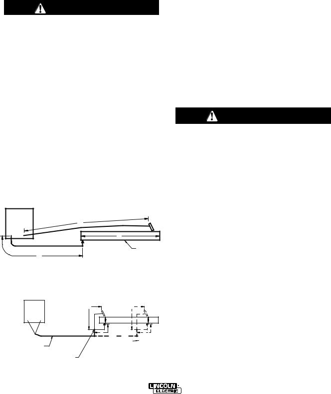
CABLE INDUCTANCE, AND ITS EFFECTS ON PULSE WELDING
For Pulse Welding processes, cable inductance will cause the welding performance to degrade. For the total welding loop length less than 50 ft.(15.24m), traditional welding cables may be used without any effects on welding performance. For the total welding loop length greater than 50 ft.(15.24m)), the K1796 Coaxial Welding Cables are recommended. The welding loop length is defined as the total of electrode cable length
(A) + work cable length (B) + work length (C) (See Figure A.3).
|
|
FIGURE A.3 |
POWER |
|
|
WAVE |
|
A |
|
|
|
|
|
C |
|
B |
WORK |
|
|
For long work piece lengths, a sliding ground should be considered to keep the total welding loop length less than 50 ft.(15.24m). (See Figure A.4.)
|
FIGURE A.4 |
|
|
|
POWER |
|
A |
|
A |
WAVE |
|
|
||
|
|
|
|
|
|
|
C |
WORK |
C |
K1796 COAXIAL CABLE |
|
BSLIDING WORK |
B |
|
|
|
|
|
|
MEASURE FROM END |
|
|
|
|
OF OUTER JACKET OF |
|
|
|
|
CABLE |
|
|
|
|
Output connections on some POWER WAVE®s are made via 1/2-13 threaded output studs located beneath the spring loaded output cover at the bottom of the case front.
Most welding applications run with the electrode being positive (+). For those applications, connect the electrode cable between the wire feeder and the positive
(+) output Twist-Mate terminal on the power source. Connect the other end of the electrode cable to the wire drive feed plate. The electrode cable lug must be against the feed plate. Be sure the connection to the feed plate makes tight metal-to-metal electrical contact. The electrode cable should be sized according to the specifications given in the output cable connections section. Connect a work lead from the negative (-) power source output Twist-Mate terminal to the work piece. The work piece connection must be firm and secure, especially if pulse welding is planned.
For additional Safety information regarding the electrode and work cable set-up, See the standard "SAFETY INFORMATION" located in the front of the Instruction Manuals.
CAUTION
Excessive voltage drops caused by poor work piece connections often result in unsatisfactory welding performance.
----------------------------------------------------------------------
NEGATIVE ELECTRODE POLARITY
When negative electrode polarity is required, such as in some Innershield applications, reverse the output connections at the power source (electrode cable to the negative (-) Twist-Mate terminal, and work cable to the positive (+) Twist-Mate terminal.
When operating with electrode polarity negative the "Electrode Sense Polarity" DIP switch must be set to the "Negative" position on the Wire Drive Feed Head PC Board. The default setting of the switch is positive electrode polarity. Consult the Power Feed instruction manual for further details.
POWER WAVE® 405M

A-4 |
INSTALLATION |
A-4 |
|
|
|
VOLTAGE SENSING
The best arc performance occurs when the PowerWaves have accurate data about the arc conditions. Depending upon the process, inductance within the electrode and work lead cables can influence the voltage apparent at the studs of the welder. Voltage sense leads improve the accuracy of the arc conditions and can have a dramatic effect on performance. Sense Lead Kits (K940-10, -25 or -50) are available for this purpose.
CAUTION
If the voltage sensing is enabled but the sense leads are missing, improperly connected, or if the electrode polarity switch is improperly configured, extremely high welding outputs may occur.
----------------------------------------------------------------------
The ELECTRODE sense lead (67) is built into the control cable, and is automatically enabled for all semi-automatic processes. The WORK sense lead (21) connects to the POWER WAVE® at the four pin connector. By default the WORK voltage is monitored at the output stud in the POWER WAVE® 405M. For more information on the WORK sense lead (21), see "Work Voltage Sensing” in the following paragraph.
Enable the voltage sense leads as follows:
TABLE A.1
Process |
Electrode Voltage |
Work Voltage |
|
Sensing 67 lead * |
Sensing 21 lead |
GMAW |
67 lead required |
21 lead optional |
GMAW-P |
67 lead required |
21 lead optional |
FCAW |
67 lead required |
21 lead optional |
GTAW |
Voltage sense at studs |
Voltage sense at studs |
GMAW |
Voltage sense at studs |
Voltage sense at studs |
SAW |
67 lead required |
21 lead optional |
CAC-C |
Voltage sense at studs |
Voltage sense at studs |
|
|
|
*The electrode voltage 67 sense lead is integral to the control cable to the wire feeder.
Work Voltage Sensing
The standard POWER WAVE® 405M’s default to the work stud (work sense lead disabled)
For processes requiring work voltage sensing, connect the (21) work voltage sense lead (K940) from the POWER WAVE® work sense lead receptacle to the work piece. Attach the sense lead to the work piece as close to the weld as practical, but not in the return current path. Enable the work voltage sensing in the POWER WAVE®. (See Dip Switch Settings and Locations in Installation Section of this manual.)
ELECTRODE VOLTAGE SENSING
Enabling or disabling electrode voltage sensing is automatically configured through software. The 67 electrode sense lead is internal to the cable to the wire feeder and always connected when a wire feeder is present.
CAUTION
Important: The electrode polarity must be configured at the feed head for all semi-automatic processes. Failure to do so may result in extremely high welding outputs.
----------------------------------------------------------------------
POWER WAVE® 405M

A-5 |
INSTALLATION |
A-5 |
|
|
|
POWER WAVE® TO SEMI-AUTOMATIC
POWER FEED WIRE FEEDER INTERCON-
NECTIONS
The POWER WAVE® 405M and semi-automatic Power Feed family communicate via a 5 conductor control cable (K1543). The control cable consists of two power leads, one twisted pair for digital communication, and one lead for voltage sensing. The cables are designed to be connected end to end for ease of extension. The output receptacle on the POWER WAVE® 405M is on the case front. The input receptacle on the Power Feed is typically located at the back of the feeder, or on the bottom of the user interface.
Due to the flexibility of the platform the configuration may vary. The following is a general description of the system. For specific configuration information, consult the semi-automatic Power Feed instruction manual.
SYSTEM DESCRIPTION
The POWER WAVE® 405M and Power Feed M family of products utilize a digital communication system called ArcLink. Simply put, ArcLink allows large amounts of information to be passed at very high speeds between components (nodes) in the system. The system requires only two wires for communication, and because of its bus-like structure, the components may be connected to the network in any order, thus simplifying the system setup.
Each "system" must contain only one power source. The number of wire feeders is determined by the type of wire feeder. Refer to the wire feeder instruction manual for details
POWER WAVE® 405M
 Loading...