


 Loading...
Kurzweil Music Systems K2661, K2600X, K2600R, K2600, K2500X Reference Manual
...FXAlgs #724-6, 728: Distortion
FXAlgs #724-6, 728: Distortion
FXAlg #724 — Mono Distortion
FXAlg #725 — MonoDistort + Cab
FXAlg #726 — MonoDistort + EQ
FXAlg #728 — StereoDistort+EQ
Small distortion algorithms
Allocation Units: 1 for Mono Distortion; 2 for MonoDistort + Cab; 2 for MonoDistort + EQ; 3 for StereoDistort + EQ
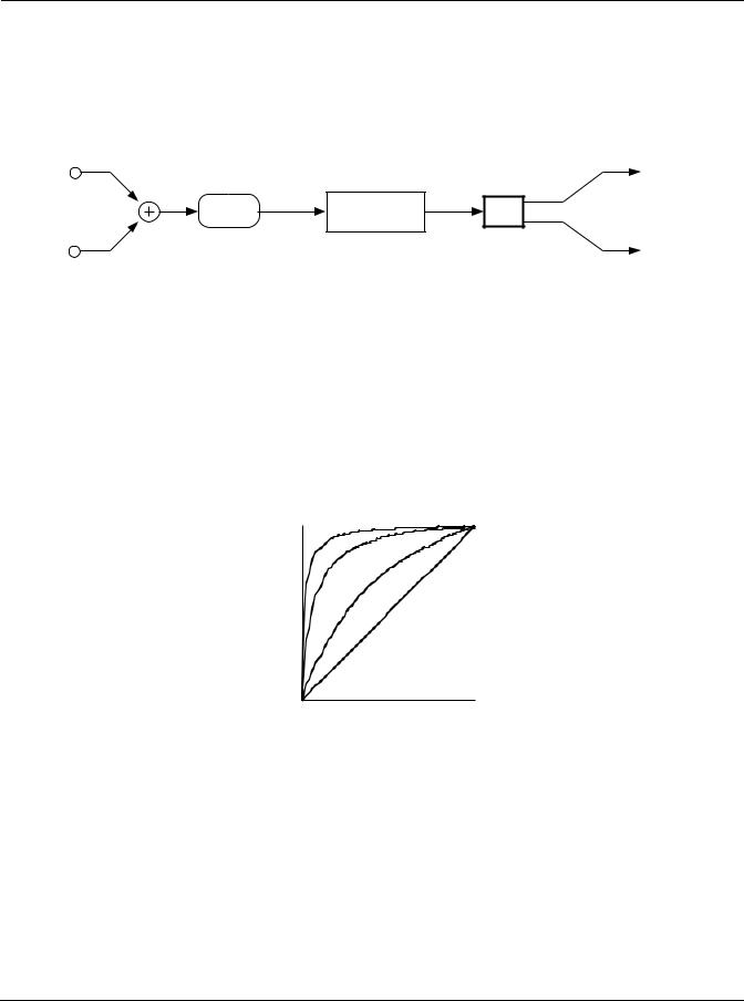
Mono Distortion sums its stereo input to mono, performs distortion followed by a hipass filter and sends the result as centered stereo.
L Input |
L Output |
|
Distortion |
R Input |
R Output |
Block diagram of Mono Distortion
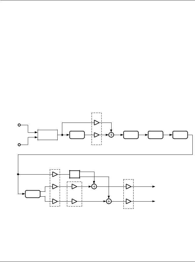
MonoDistort + EQ is similar to Mono Distortion except the single hipass filter is replaced with a pair of second-order hipass/lowpass filters to provide rudimentary speaker cabinet modeling. The hipass and lowpass filters are then followed by an EQ section with bass and treble shelf filters and two parametric mid filters.
L Input |
Cabinet |
L Output |
Distortion |
|
EQ |
R Input |
|
R Output |
Block diagram of MonoDistort + EQ
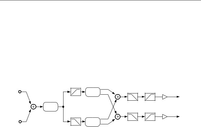
StereoDistort + EQ processes the left and right channels separately, though there is only one set of parameters for both channels. The stereo distortion has only one parametric mid filter.
L Input |
Distortion |
EQ |
L Output |
R Input |
Distortion |
EQ |
R Output |
|
Block diagram of StereoDistort+EQ |
|
|
Algorithm Reference-94
FXAlgs #724-6, 728: Distortion
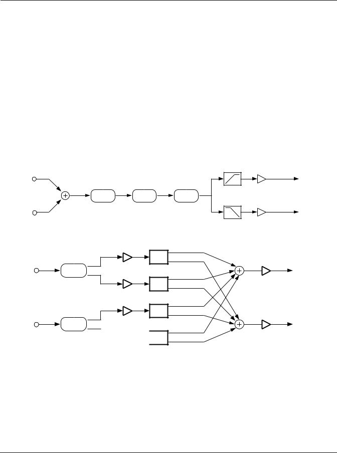
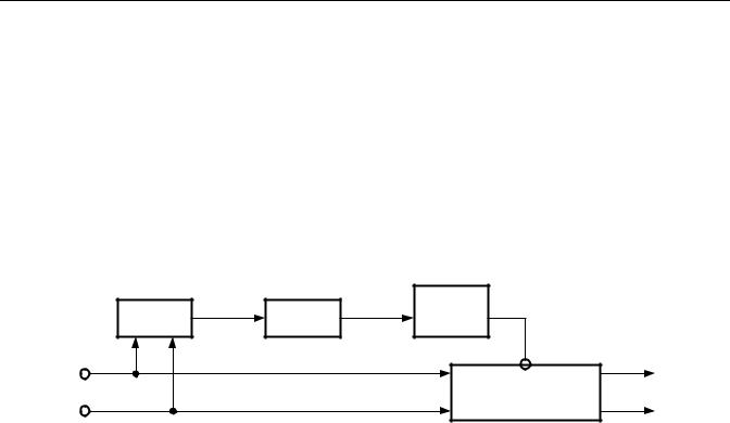
MonoDistort + Cab is also similar to Mono Distortion except the hipass is replaced by a full speaker cabinet model. There is also a panner to route the mono signal between left and right outputs. In MonoDistort + Cab, the distortion is followed by a model of a guitar amplifier cabinet. The model can be bypassed, or there are eight presets which were derived from measurements of real cabinets. (See descriptions of FXAlgs #729-732 in this book for more information.)
L Input |
|
L Output |
|
Distortion |
Cabinet |
Pan |
|
Filter |
|||
|
|
||
R Input |
|
R Output |
Block diagram of MonoDistort + Cab
The distortion algorithm will soft clip the input signal. The amount of soft clipping depends on how high the distortion drive parameter is set. Soft clipping means that there is a smooth transition from linear gain to saturated overdrive. Higher distortion drive settings cause the transition to become progressively sharper or “harder”. The distortion never produces hard or digital clipping, but it does approach it at high drive settings. When you increase the distortion drive parameter you are increasing the gain of the algorithm until the signal reaches saturation. You will have to compensate for increases in drive gain by reducing the output gain. These algorithms will not digitally clip unless the output gain is over-driven.
Output |
Input |
Input/Output Transfer Characteristic of Soft Clipping at Various Drive Settings
Signals which are symmetric in amplitude (they have the same shape if they are inverted, positive for negative) will usually produce odd harmonic distortion. For example, a pure sine wave will produce smaller copies of itself at 3, 5, 7, etc. times the original frequency of the sine wave. In the MonoDistort + EQ, a dc offset may be added to the signal to break the amplitude symmetry and will cause the distortion to produce even harmonics. This can add a “brassy” character to the distorted sound. The dc offset added prior to distortion gets removed at a later point in the algorithm.
Algorithm Reference-95

FXAlgs #724-6, 728: Distortion
Parameters - Mono Distortion:
PAGE 1
Wet/Dry |
0 to 100%wet |
Out Gain |
Off, -79.0 to 24.0 dB |
|
|
|
|
Dist Drive |
0 to 96 dB |
|
|
|
|
|
|
Warmth |
16 to 25088 Hz |
|
|
|
|
|
|
Highpass |
16 to 25088 Hz |
|
|
|
|
|
|
MonoDistort + Cab:
PAGE 1
Wet/Dry |
0 to 100%wet |
Out Gain |
Off, -79.0 to 24.0 dB |
|
|
|
|
Dist Drive |
0 to 96 dB |
|
|
|
|
|
|
Warmth |
16 to 25088 Hz |
Cab Bypass |
In or Out |
|
|
|
|
|
|
Cab Preset |
Basic |
|
|
|
|
MonoDistort + EQ:
PAGE 1
|
Wet/Dry |
0 to 100%wet |
Out Gain |
Off, -79.0 to 24.0 dB |
|
|
|
|
|
|
Dist Drive |
0 to 96 dB |
|
|
|
|
|
|
|
|
Warmth |
16 to 25088 Hz |
dc Offset |
-100 to 100% |
|
|
|
|
|
|
Cabinet HP |
16 to 25088 Hz |
Cabinet LP |
16 to 25088 Hz |
|
|
|
|
|
PAGE 2 |
|
|
|
|
|
|
|
|
|
|
Bass Gain |
-79.0 to 24.0 dB |
Treb Gain |
-79.0 to 24.0 dB |
|
|
|
|
|
|
Bass Freq |
16 to 25088 Hz |
Treb Freq |
16 to 25088 Hz |
|
|
|
|
|
|
Mid1 Gain |
-79.0 to 24.0 dB |
Mid2 Gain |
-79.0 to 24.0 dB |
|
|
|
|
|
|
Mid1 Freq |
16 to 25088 Hz |
Mid2 Freq |
16 to 25088 Hz |
|
|
|
|
|
|
Mid1 Width |
0.010 to 5.000 oct |
Mid2 Width |
0.010 to 5.000 oct |
|
|
|
|
|
StereoDistort+EQ: |
|
|
||
PAGE 1 |
|
|
|
|
|
|
|
|
|
|
Wet/Dry |
0 to 100%wet |
Out Gain |
Off, -79.0 to 24.0 dB |
|
|
|
|
|
|
Dist Drive |
0 to 96 dB |
|
|
|
|
|
|
|
|
Warmth |
16 to 25088 Hz |
|
|
|
|
|
|
|
|
Cabinet HP |
16 to 25088 Hz |
Cabinet LP |
16 to 25088 Hz |
|
|
|
|
|
Algorithm Reference-96

|
|
|
|
FXAlgs #724-6, 728: Distortion |
|
PAGE 2 |
|
|
|
|
|
|
|
|
|
|
|
|
Bass Gain |
-79.0 to 24.0 dB |
Treb Gain |
-79.0 to 24.0 dB |
|
|
|
|
|
|
|
|
Bass Freq |
16 to 25088 Hz |
Treb Freq |
16 to 25088 Hz |
|
|
|
|
|
|
|
|
Mid Gain |
-79.0 to 24.0 dB |
|
|
|
|
|
|
|
|
|
|
Mid Freq |
16 to 25088 Hz |
|
|
|
|
|
|
|
|
|
|
Mid Width |
0.010 to 5.000 oct |
|
|
|
|
|
|
|
|
|
Wet/Dry |
The amount of distorted (wet) signal relative to unaffected (dry) signal. |
Out Gain |
The overall gain or amplitude at the output of the effect. For distortion, it is often |
|
necessary to turn the output gain down as the distortion drive is turned up. |
Dist Drive |
Applies a boost to the input signal to overdrive the distortion algorithm. When |
|
overdriven, the distortion algorithm will soft-clip the signal. Since distortion drive will |
|
make your signal very loud, you may have to reduce the Out Gain as the drive is |
|
increased. |
Warmth |
A lowpass filter in the distortion control path. This filter may be used to reduce some of |
|
the harshness of some distortion settings without reducing the bandwidth of the signal. |
Cab Bypass |
The guitar amplifier cabinet simulation may be bypassed. When set to “In”, the cabinet |
|
simulation is active; when set to “Out”, there is no cabinet filtering. [MonoDistort + Cab] |
Cab Preset |
Eight preset cabinets have been created based on measurements of real guitar amplifier |
|
cabinets. The presets are Basic, Lead 12, 2x12, Open 12, Open 10, 4x12, Hot 2x12, and Hot |
|
12. See description of FX Algs #729-732 for more information. [MonoDistort + Cab] |
Highpass |
Allows you to reduce the bass content of the distortion content. If you need more |
|
filtering to better simulate a speaker cabinet, you will have to choose a larger distortion |
|
algorithm. [Mono Distortion] |
MonoDistort + EQ and StereoDistort+EQ |
|
Cabinet HP |
A hipass filter which controls the low-frequency limit of a simulated loudspeaker |
|
cabinet. |
Cabinet LP |
A lowpass filter which controls the high-frequency limit of a simulated cabinet. |
Bass Gain |
The amount of boost or cut that the bass shelving filter should apply to the low |
|
frequency signals in dB. Every increase of 6 dB approximately doubles the amplitude of |
|
the signal. Positive values boost the bass signal below the specified frequency. Negative |
|
values cut the bass signal below the specified frequency. |
Bass Freq |
The center frequency of the bass shelving filter in intervals of one semitone. |
Treb Gain |
The amount of boost or cut that the treble shelving filter should apply to the high |
|
frequency signals in dB. Every increase of 6 dB approximately doubles the amplitude of |
|
the signal. Positive values boost the treble signal above the specified frequency. Negative |
|
values cut the treble signal above the specified frequency. |
Treb Freq |
The center frequency of the treble shelving filter in intervals of one semitone. |
Mid Gain |
The amount of boost or cut that the mid parametric filter should apply in dB. Every |
|
increase of 6 dB approximately doubles the amplitude of the signal. Positive values |
|
boost the signal at the specified frequency. Negative values cut the signal at the |
|
specified frequency. |
Mid Freq |
The center frequency of the mid parametric filter in intervals of one semitone. The boost |
|
or cut will be at a maximum at this frequency. |
Mid Wid |
The bandwidth of the mid parametric filter may be adjusted. You specify the bandwidth |
|
in octaves. Small values result in a very narrow filter response. Large values result in a |
|
very broad response. |
Algorithm Reference-97

FXAlg #727: PolyDistort + EQ
FXAlg #727: PolyDistort + EQ
Eight-stage distortion followed by equalization
Allocation Units: 2
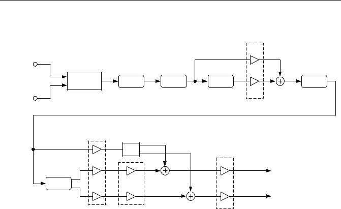
PolyDistort + EQ is a distortion algorithm followed by equalization. The algorithm consists of an input gain stage, and then eight cascaded distortion stages. Each stage is followed by a one-pole LP filter. There is also a one pole LP in front of the first stage. After the distortion there is a 4-band EQ section: Bass, Treble, and two Parametric Mids.
L Input |
|
|
|
Dry |
|
|
|
|
|
Dist Drive |
|
|
|
|
R Input |
LP0 |
|
|
|
|
|
|
|
|
Distort |
|
Distort |
|
|
Curve 1 |
|
Curve 2 |
|
|
|
LP1 |
|
LP2 |
|
Distort |
|
Distort |
|
|
Curve 3 |
|
Curve 4 |
|
|
|
LP3 |
|
LP4 |
|
Distort |
|
Distort |
|
|
Curve 5 |
|
Curve 6 |
|
|
|
LP5 |
|
LP6 |
|
Distort |
|
Distort |
|
|
Curve 7 |
|
Curve 8 |
|
|
|
LP7 |
|
LP8 |
|
|
|
Parametric |
L Output |
|
|
|
|
||
Bass |
Treble |
Mid1 |
Mid2 |
Wet |
R Output |
||||
|
|
|
|
Dry |
Block diagram of PolyDistort + EQ
Algorithm Reference-98

FXAlg #727: PolyDistort + EQ
PolyDistort is an unusual distortion algorithm which provides a great number of parameters to build a distortion sound from the ground up. The eight distortion stages each add a small amount of distortion to the sound. Taken together, they can produce a very harsh heavy metal sound. Between each distortion stage is a lopass filter. The lopass filters work with the distortion stages to help mellow out the sound. Without any lopass filters the distortion will get very harsh and raspy.
Stages of distortion can be removed by setting the Curve parameter to 0. You can then do a 6, 4, or 2 stage distortion algorithm. The corresponding lopasses should be turned off if there is no distortion in a section. More than 4 stages seem necessary for lead guitar sounds. For a cleaner sound, you may want to limit yourself to only 4 stages.
Once you have set up a distorted sound you are satisfied with, the Dist Drive parameter controls the input gain to the distortion, providing a single parameter for controlling distortion amount. You will probably find that you will have to cut back on the output gain as you drive the distortion louder.
Post-distortion EQ is definitely needed to make things sound right. This should be something like a guitar speaker cabinet simulator, although not exactly, since we are already doing a lot of lopass filtering inside the distortion itself. Possible EQ settings you can try are Treble -20 dB at 5 kHz, Bass -6 dB at 100 Hz, Mid1, wide, +6 dB at 2 kHz, Mid2, wide, +3 dB at 200 Hz, but of course you should certainly experiment to get your sound. The Treble is helping to remove raspiness, the Bass is removing the extreme low end like an open-back guitar cabinet (not that guitar speakers have that much low end anyway), Mid1 adds enough highs so that things can sound bright even in the presence of all the HF roll-off, and Mid2 adds some warmth. Your favorite settings will probably be different. Boosting the Treble may not be a good idea.
Pre-distortion EQ, available on the KDFX Studio INPUT pages, is also useful for shaping the sound. EQ done in front of the distortion will not be heard as simple EQ, because the distortion section makes an adjustment in one frequency range felt over a much wider range due to action of the distortion. Simple post-EQ is a bit too obvious for the ear, and it can get tiring after a while.
Parameters:
PAGE 1
|
Wet/Dry |
0 to 100%wet |
Out Gain |
Off, -79.0 to 24.0 dB |
|
|
|
|
|
|
Dist Drive |
Off, -79.0 to 48.0 dB |
|
|
|
|
|
|
|
PAGE 2 |
|
|
|
|
|
|
|
|
|
|
Curve 1 |
0 to 127% |
Curve 5 |
0 to 127% |
|
|
|
|
|
|
Curve 2 |
0 to 127% |
Curve 6 |
0 to 127% |
|
|
|
|
|
|
Curve 3 |
0 to 127% |
Curve 7 |
0 to 127% |
|
|
|
|
|
|
Curve 4 |
0 to 127% |
Curve 8 |
0 to 127% |
|
|
|
|
|
PAGE 2 |
|
|
|
|
|
|
|
|
|
|
LP0 Freq |
16 to 25088 Hz |
|
|
|
|
|
|
|
|
LP1 Freq |
16 to 25088 Hz |
LP5 Freq |
16 to 25088 Hz |
|
|
|
|
|
|
LP2 Freq |
16 to 25088 Hz |
LP6 Freq |
16 to 25088 Hz |
|
|
|
|
|
|
LP3 Freq |
16 to 25088 Hz |
LP7 Freq |
16 to 25088 Hz |
|
|
|
|
|
|
LP4 Freq |
16 to 25088 Hz |
LP8 Freq |
16 to 25088 Hz |
|
|
|
|
|
Algorithm Reference-99

FXAlg #727: PolyDistort + EQ
PAGE 4
Bass Gain |
-79.0 to 24.0 dB |
Treb Gain |
-79.0 to 24.0 dB |
|
|
|
|
Bass Freq |
16 to 25088 Hz |
Treb Freq |
16 to 25088 Hz |
|
|
|
|
Mid1 Gain |
-79.0 to 24.0 dB |
Mid2 Gain |
-79.0 to 24.0 dB |
|
|
|
|
Mid1 Freq |
16 to 25088 Hz |
Mid2 Freq |
16 to 25088 Hz |
|
|
|
|
Mid1 Width |
0.010 to 5.000 oct |
Mid2 Width |
0.010 to 5.000 oct |
|
|
|
|
Wet/Dry |
This is a simple mix of the distorted signal relative to the dry undistorted input signal. |
Out Gain |
The overall gain or amplitude at the output of the effect. For distortion, it is often |
|
necessary to turn the output gain down as the distortion drive is turned up. |
Dist Drive |
Applies gain to the input prior to distortion. It is the basic “distortion drive” control. |
|
Anything over 0 dB could clip. Normally clipping would be bad, but the distortion |
|
algorithm tends to smooth things out. Still, considering that for some settings of the |
|
other parameters you would have to back off the gain to -48 dB in order to get a not very |
|
distorted sound for full scale input, you should go easy on this amount. |
Curve n |
The curvature of the individual distortion stages. 0% is no curvature (no distortion at |
|
all). At 100%, the curve bends over smoothly and becomes perfectly flat right before it |
|
goes into clipping. |
LP n Freq |
These are the one-pole lopass controls. LP0 Freq handles the initial lopass prior to the |
|
first distortion stage. The other lopass controls follow their respective distortion stages. |
|
With all lopasses out of the circuit (set to the highest frequency), the sound tends to be |
|
too bright and raspy. With less distortion drive, less filtering is needed. If you turn off a |
|
distortion stage (set to 0%), you should turn of the lopass filter by setting it to the highest |
|
frequency. |
Bass Gain |
The amount of boost or cut that the bass-shelving filter should apply to the low- |
|
frequency signals in dB. Every increase of 6 dB approximately doubles the amplitude of |
|
the signal. Positive values boost the bass signal below the specified frequency. Negative |
|
values cut the bass signal below the specified frequency. |
Bass Freq |
The center frequency of the bass shelving filter in intervals of one semitone. |
Treb Gain |
The amount of boost or cut that the treble-shelving filter should apply to the high- |
|
frequency signals in dB. Every increase of 6 dB approximately doubles the amplitude of |
|
the signal. Positive values boost the treble signal above the specified frequency. Negative |
|
values cut the treble signal above the specified frequency. |
Treb Freq |
The center frequency of the treble shelving filter in intervals of one semitone. |
Mid Gain |
The amount of boost or cut that the mid parametric filter should apply in dB. Every |
|
increase of 6 dB approximately doubles the amplitude of the signal. Positive values |
|
boost the signal at the specified frequency. Negative values cut the signal at the |
|
specified frequency. |
Mid Freq |
The center frequency of the mid parametric filter in intervals of one semitone. The boost |
|
or cut will be at a maximum at this frequency. |
Mid Wid |
The bandwidth of the mid parametric filter may be adjusted. The bandwidth is specified |
|
in octaves. Small values result in a very narrow filter response. Large values result in a |
|
very broad response. |
Algorithm Reference-100

Tube Amp/Distortion/Delay Combinations
Tube Amp/Distortion/Delay Combinations
FXAlg #729: TubeAmp<>MD>Chor
FXAlg #730: TubeAmp<>MD>Flan
FXAlg #731: PolyAmp<>MD>Chor
FXAlg #732: PolyAmp<>MD>Flan
Mono distortion circuits in combination with moving delays, and a stereo chorus or stereo flange
Allocation Units:3 each
Each of these four algorithms offer a flexible chain of effects designed primarily for guitar processing. Each chain offers a different combination of a 3-band tone control, tube-amp distortion drive, poly-amp distortion drive, cabinet simulation, chorus, flange, and a generic moving delay. The entire algorithm is monaural with the exception of the final chorus or flange at the end of each chain, which have one input and a stereo output.
At the beginning of each chain is a 3-band tone control authentically re-creating the response in many guitar preamps based on real measurements collected by Kurzweil engineers. It is adjusted with the Bass Tone, Mid Tone, and Treb Tone controls with values ranging from 0 to 10 commonly found on many guitar amps. The flattest frequency response is obtained by setting Mid Tone to 10.0, and both Bass and Treb Tone controls to 0.0.
The tone controls are integrated with one of two types of preamp drive circuits: TubeAmp and PolyAmp. The TubeAmp faithfully models the response and smooth distortion caused by overloading a vacuum tube circuit. PolyAmp is closely related to the PolyDistort algorithm offering a brighter sound quality with more sustain. The amount of distortion is controlled by adjusting the Tube Drive or Poly Drive parameter. High frequency energy caused by distortion can be rolled off by using the Warmth parameter.
Following the distortion drive element is a cabinet simulator. The cabinet simulator models the responses of various types of mic’d guitar cabinets. The preset can be selected using the Cab Preset parameter. The following is the list of cabinet presets and their descriptions:
Basic |
Flat response from 100 Hz to 4 kHz with 4th order roll-offs (24dB/oct) on each end |
Lead 12 |
Open back hard American type with one 12” driver |
2x12 |
Closed back classic American type with two 12” drivers |
Open 12 |
Open back classic American type with one 12” driver |
Open 10 |
Open back classic American type with one 10” driver |
4x12 |
Closed back British type with four 12” drivers |
Hot 2x12 |
Closed back hot rod type with two 12” drivers |
Hot 12 |
Open back hot rod type with one 12” driver |
Algorithm Reference-101
Tube Amp/Distortion/Delay Combinations
The cabinet can by switched on or off with the Cab In/Out parameter. The Cab Pan parameter adjusts the final pan position of the cabinet at the output of the algorithm, but this does not affect the cabinet signal fed into the final stereo flange or chorus. If Ch Wet/Dry or Fl Wet/Dry is set to 100%, this pan control will not have any audible affect since the entire output of the cabinet is fed into the flange or chorus instead of the algorithm output.
At the end of the chain is either a chorus or a flange controlled by parameters beginning with “Ch” or “Fl” respectively. The chorus and flange have mono inputs and stereo outputs. Each is a standard KDFX single tap dual channel chorus (see FXAlg #150) or flange (see FXAlg#154) with independent controls for left and right channels found in many other 1-PAU combination algorithms. The Ch Wet/Dry or Fl Wet/Dry control determines the final output mix of the algorithm. When set at 0%, only the cabinet simulator output is fed to the output of the algorithm. At 100%, only the output of the chorus or flange is heard. Left/right balance specifically for the chorus or flange can be adjusted with the Out Bal control.
In addition, there is a generic monaural moving delay segment. Its parameters begin with the letters “MD”. The moving delay is flexible enough that it can serve as a chorus, flange, or straight delay. For more detailed information, refer to the section describing the Dual MovDelay and Quad MovDelay algorithms (FXAlgs #715-716). As implemented in these four algorithms, it can be inserted either before the tone controls (PreDist), or after the distortion drive (PostDist), or bypassed altogether. This is selected with the MD Insert parameter. Also provided is the MD Wet/Dry parameter that mixes the output of the moving delay circuit with its own input to be fed into the next effect in the chain.
|
|
|
MD Wet/Dry |
|
|
L Input |
Input Bal |
|
|
|
|
|
|
|
|
|
|
|
Blend |
Moving |
Tone |
Tube |
Cab |
|
Delay |
Amp |
Simulator |
||
|
|
|
|||
R Input |
|
|
|
|
|
|
Ch Wet/Dry |
|
|
|
|
|
|
Pan |
|
|
|
|
|
|
|
|
L Output |
|
Chorus |
|
|
|
|
|
|
|
|
|
R Output |
|
|
Ch Out Bal |
Out Gain |
|
|
|
|
|
|
|
TubeAmp<>MD>Chor with moving delay inserted PreDist
Algorithm Reference-102
Tube Amp/Distortion/Delay Combinations
|
|
|
|
|
MD Wet/Dry |
L Input |
Input Bal |
|
|
|
|
|
|
|
|
|
|
|
Blend |
Tone |
Tube |
Moving |
Cab |
|
Amp |
Delay |
Simulator |
||
|
|
|
|||
R Input |
|
|
|
|
|
|
Ch Wet/Dry |
|
|
|
|
|
|
Pan |
|
|
|
|
|
|
|
|
L Output |
|
Chorus |
|
|
|
|
R Output
Ch Out Bal
Out Gain
TubeAmp<>MD>Chor with moving delay inserted PostDist
Parameters:
PAGE 1
|
In/Out |
In or Out |
Out Gain |
Off; -79.0 to 24.0 dB |
|
|
|
|
|
|
|
|
Input Bal |
-100 to 100% |
|
|
|
|
|
|
|
|
|
PAGE 2 (TubeAmp algs) |
|
|
|
||
|
|
|
|
|
|
|
|
|
Tube Drive |
Off; -79.0 to 60.0 dB |
|
|
|
|
|
|
|
|
|
|
Warmth |
16 to 25088 Hz |
|
|
|
|
|
|
|
|
Bass Tone |
0.0 to 10.0 |
|
|
|
|
|
|
|
|
|
|
Mid Tone |
0.0 to 10.0 |
Cab In/Out |
In or Out |
|
|
|
|
|
|
|
|
Treb Tone |
0.0 to 10.0 |
Cab Preset |
Open 12, ... |
|
|
|
|
|
|
|
|
|
|
Cab Pan |
-100 to 100% |
|
|
|
|
|
|
|
PAGE 2 (PolyAmp algs) |
|
|
|
||
|
|
|
|
|
|
|
|
|
Poly Drive |
0.0 to 60.0 dB |
|
|
|
|
|
|
|
|
|
|
Warmth |
16 to 25088 Hz |
|
|
|
|
|
|
|
|
Bass Tone |
0.0 to 10.0 |
|
|
|
|
|
|
|
|
|
|
Mid Tone |
0.0 to 10.0 |
Cab In/Out |
In or Out |
|
|
|
|
|
|
|
|
Treb Tone |
0.0 to 10.0 |
Cab Preset |
Open 12, ... |
|
|
|
|
|
|
|
|
|
|
Cab Pan |
-100 to 100% |
|
|
|
|
|
|
|
|
|
|
|
|
|
Algorithm Reference-103
Tube Amp/Distortion/Delay Combinations
PAGE 3
|
MD Insert |
Post Dist, ... |
MD Delay |
0.0 to 1000.0 ms |
|
|
|
|
|
|
MD Wet/Dry |
0 to 100% |
MD LFOMode |
Flange, ... |
|
|
|
|
|
|
|
|
MD LFORate |
0.00 to 10.00 Hz |
|
|
|
|
|
|
|
|
MD LFODpth |
0.0 to 200.0% |
|
|
|
|
|
|
|
|
MD Fdbk |
-100 to 100% |
|
|
|
|
|
PAGE 4 (Chorus algs) |
|
|
||
|
|
|
|
|
|
Ch Rate L |
0.01 to 10.00 Hz |
Ch Rate R |
0.01 to 10.00 Hz |
|
|
|
|
|
|
Ch Depth L |
0.0 to 100.0 cts |
Ch Depth R |
0.0 to 100.0 cts |
|
|
|
|
|
|
Ch Delay L |
0 to 720 ms |
Ch Delay R |
0 to 720 ms |
|
|
|
|
|
|
Ch Fdbk L |
-100 to 100% |
Ch Fdbk R |
-100 to 100% |
|
|
|
|
|
|
Ch PtchEnv |
Triangle or Trapzoid |
|
|
|
|
|
|
|
|
ChWet/Dry |
0 to 100% |
Ch Out Bal |
-100 to 100% |
|
|
|
|
|
PAGE 4 (Flange algs) |
|
|
||
|
|
|
|
|
|
Fl Rate |
0 to 32 bts |
Fl Tempo |
System; 1 to 255 BPM |
|
|
|
|
|
|
Fl Xcurs L |
0 to 230 ms |
Fl Xcurs R |
0 to 230 ms |
|
|
|
|
|
|
Fl Delay L |
0 to 230 ms |
Fl Delay R |
0 to 230 ms |
|
|
|
|
|
|
Fl Fdbk L |
-100 to 100% |
Fl Fdbk R |
-100 to 100% |
|
|
|
|
|
|
Fl Phase L |
0 to 360 deg |
Fl Phase R |
0 to 360 deg |
|
|
|
|
|
|
Fl Wet/Dry |
0 to 100% |
Fl Out Bal |
-100 to 100% |
|
|
|
|
|
In/Out |
Toggles the entire effect on or off. When off, the input signal is passed. |
Input Bal |
Adjusts the ratio of left and right algorithm inputs to be summed into the monaural |
|
signal that is processed by the effect. 0% blends equal amount of left and right. Negative |
|
values blend increasing amounts of left, while positive values blend increasing amounts |
|
of right. |
Out Gain |
The overall gain or amplitude at the output of the effect. |
Bass Tone, Mid Tone, Treb Tone Adjusts the 3 bands of the tone control integrated with the distortion drive circuit.
|
Flattest response is obtained by setting Mid Tone to 10.0, and both Bass Tone and Treb |
|
Tone to 0.0. |
Tube Drive, Poly Drive |
Adjusts the gain into each distortion circuit. Higher values produce more distortion. |
Warmth |
Adjusts a 1-pole (6dB/oct) lopass filter applied after distortion. |
Cab In/Out |
Turns the cabinet simulator on or off. |
Cab Preset |
Selects the preset cabinet type. |
Cab Pan |
Adjusts the output pan position of the cabinet simulator signal that is mixed at the |
|
output of the algorithm. Note that when Ch Wet/Dry or Fl Wet/Dry is set to 100%, no |
|
signal from the cabinet is mixed directly to the output, so this parameter has no affect. |
MD Insert |
Selects where in the signal chain the moving delay is to be. PreDist places it before the |
|
distortion and tone circuit. PostDist places it between the distortion circuit and cabinet |
|
simulator, and Bypass takes it completely out of the path. |
MD Wet/Dry |
Adjusts the ratio of the moving delay output mixed with its own input to be fed to the |
|
next effect in the chain. |
|
|
Algorithm Reference-104

|
Tube Amp/Distortion/Delay Combinations |
MD Delay |
Adjusts the delay time for the moving delay circuit, which is the center of LFO |
|
excursion. |
MD LFOMode |
Adjusts the LFO excursion type. In Flange mode, the LFO is optimized for flange effects |
|
and LFO Dpth adjusts the excursion amount. In ChorTri and ChorTrap modes, the LFO |
|
is optimized for triangle and trapezoidal pitch envelopes respectively, and LFO Dpth |
|
adjusts the amount of chorus detuning. In Delay mode, the LFO is turned off leaving a |
|
basic delay. LFO Rate and LFO Dpth in Delay mode are disabled. |
MD LFORate |
Adjusts the LFO speed for the moving delay circuit. |
MD LFODpth |
In Flange LFO mode, this adjusts an arbitrary LFO excursion amount. In ChorTri and |
|
ChorTrap modes, this controls the chorus detune amount. In delay mode, this is |
|
disabled. |
MD Fdbk |
Adjusts the level of the moving delay circuit output signal fed back into its own input. |
|
Negative values polarity-invert the feedback signal. |
Ch Wet/Dry, Fl Wet/Dry |
Adjusts the ratio of flange or chorus signal and the cabinet simulator signal fed to |
|
the output of the algorithm. 0% feeds only the cabinet simulator to the output bypassing |
|
the final chorus or flange. 100% feeds only the flange or chorus to the output. |
Ch Out Bal, Fl Out Bal |
Adjusts the left/right output balance of the chorus or flange signal. Negative values |
|
balance toward the left while positive values balance toward the right. |
Algorithm Reference-105
FXAlg #733: VibChor+Rotor 2 • FXAlg #734: VibChor+Rotor 4
FXAlg #733: VibChor+Rotor 2 •
FXAlg #734: VibChor+Rotor 4
Vibrato/chorus, through optional distortion, into rotating speaker
Allocation Units: 2 for VibChor+Rotor 2; 4 for VibChor+Rotor 4
The VibChor+Rotor algorithms contain multiple effects designed for the Hammond B3® emulation (KB3 mode). These effects are the Hammond® vibrato/chorus, amplifier distortion, and rotating speaker (Leslie®). Each of these effects may be turned off or bypassed, or the entire algorithm may be bypassed.
L Input |
|
Pan |
Cabinet |
L Output |
|
|
Rotator |
|
|
|
|
Pan |
|
|
Vibrato/ |
Distortion |
Mic Levels |
|
Out Gain |
Chorus |
(Optional) |
|
||
|
|
|
||
|
|
Pan |
Cabinet |
|
|
|
Rotator |
|
|
R Output |
|
Pan |
|
R Output |
Block diagram of VibChor+Rotor
The first effect in the chain is the Hammond vibrato/chorus algorithm. The vibrato/chorus has six settings which are the same as those used in the Hammond B3: three vibrato (V1, V2, V3) and three chorus (C1, C2, C3) settings. In VibChor+Rotor 4, the vibrato chorus has been carefully modeled after the electro-mechanical vibrato/chorus in the B3. The vibrato/chorus in VibChor+Rotor 2 uses a conventional design, which has been set to match the B3 sound as closely as possible, but does not quite have the same character as the VibChor+Rotor 4 vibrato/chorus.
In VibChor+Rotor 4 an amplifier distortion algorithm follows the vibrato/chorus. See the section in this book on FXAlg #724 for more information about the distortion algorithm.
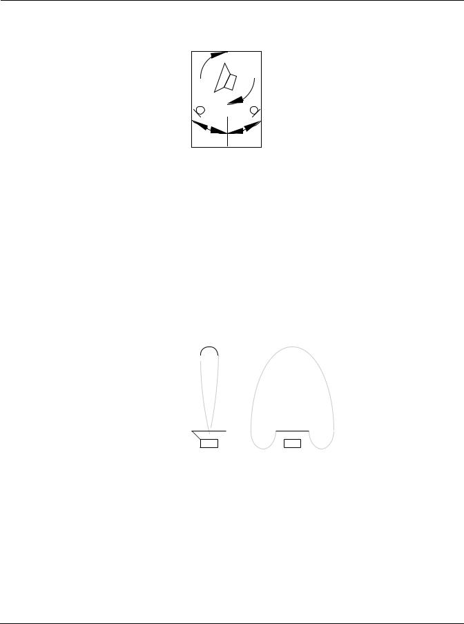
Finally, the signal passes through a rotating speaker routine. The rotating speaker has separately controllable tweeter and woofer drivers. The signal is split into high and low frequency bands and the two bands are run through separate rotors. The upper and lower rotors each have a pair of virtual microphones which can be positioned at varying positions (angles) around the rotors. An angle of 0° is loosely defined as the front. You can also control the levels and left-right panning of each virtual microphone. The signal is then passed through a final lowpass filter to simulate the band-limiting effect of the speaker cabinet.
Algorithm Reference-106
FXAlg #733: VibChor+Rotor 2 • FXAlg #734: VibChor+Rotor 4
positive angles |
negative angles |
Rotating speaker with virtual microphones
For the rotating speakers, you can control the crossover frequency of the high and low frequency bands (the frequency where the high and low frequencies get separated). The rotating speakers for the high and low frequencies have their own controls. For both, the rotation rate, the effective driver size and tremolo can be set. The rotation rate sets how fast the rotating speaker is spinning. The effective driver size is the radius of the path followed by the speaker relative to its center of rotation. This parameter is used to calculate the resulting Doppler shift of the moving speaker. Doppler shift is the pitch shift that occurs when a sound source moves toward or away from you the listener. In a rotating speaker, the Doppler shift will sound like vibrato. As well as Doppler shift, there will be some acoustic shadowing as the speaker is alternately pointed away from you and toward you. The shadowing is simulated with a tremolo over which you can control the tremolo depth and “width”. The high-frequency driver (rotating horn) will have a narrower acoustic beam width (dispersion) than the low-frequency driver, and the widths of both may be adjusted. Note that it can take up to one full speaker rotation before you hear changes to tremolo when parameter values are changed. Negative microphone angles take a longer time to respond to tremolo changes than positive microphone angles.
(i) |
(ii) |
Acoustic beams for (i) low frequency driver and (ii) high frequency driver.
You can control resonant modes within the rotating speaker cabinet with the Lo and Hi Resonate parameters. For a realistic rotating speaker, the resonance level and delay excursion should be set quite low. High levels will give wild pitch shifting.
Algorithm Reference-107

FXAlg #733: VibChor+Rotor 2 • FXAlg #734: VibChor+Rotor 4
Parameters:
PAGE 1
|
In/Out |
In or Out |
Out Gain |
Off, -79.0 to 24.0 dB |
|
|
|
|
|
|
VibChInOut |
In or Out |
Dist Drive |
0 to 96 dB |
|
|
|
|
|
|
Vib/Chor |
V1 |
DistWarmth |
16 to 25088 Hz |
|
|
|
|
|
|
Roto InOut |
In or Out |
Cabinet LP |
16 to 25088 Hz |
|
|
|
|
|
PAGE 2 |
|
|
|
|
|
|
|
|
|
|
Xover |
16 to 25088 Hz |
|
|
|
|
|
|
|
|
Lo Gain |
Off, -79.0 to 24.0 dB |
Hi Gain |
Off, -79.0 to 24.0 dB |
|
|
|
|
|
|
Lo Rate |
-10.00 to 10.00 Hz |
Hi Rate |
-10.00 to 10.00 Hz |
|
|
|
|
|
|
Lo Size |
0 to 250 mm |
Hi Size |
0 to 250 mm |
|
|
|
|
|
|
Lo Trem |
0 to 100% |
Hi Trem |
0 to 100% |
|
|
|
|
|
|
Lo Beam W |
45.0 to 360.0 deg |
Hi Beam W |
45.0 to 360.0 deg |
|
|
|
|
|
PAGE 3 |
|
|
|
|
|
|
|
|
|
|
LoMicA Pos |
-180.0 to 180.0 deg |
LoMicB Pos |
-180.0 to 180.0 deg |
|
|
|
|
|
|
LoMicA Lvl |
0 to 100% |
LoMicB Lvl |
0 to 100% |
|
|
|
|
|
|
LoMicA Pan |
-100 to 100% |
LoMicB Pan |
-100 to 100% |
|
|
|
|
|
|
HiMicA Pos |
-180.0 to 180.0 deg |
HiMicB Pos |
-180.0 to 180.0 deg |
|
|
|
|
|
|
HiMicA Lvl |
0 to 100% |
HiMicB Lvl |
0 to 100% |
|
|
|
|
|
|
HiMicA Pan |
-100 to 100% |
HiMicB Pan |
-100 to 100% |
|
|
|
|
|
PAGE 4 |
|
|
|
|
|
|
|
|
|
|
LoResonate |
0 to 100% |
HiResonate |
0 to 100% |
|
|
|
|
|
|
Lo Res Dly |
10 to 2550 samp |
Hi Res Dly |
10 to 2550 samp |
|
|
|
|
|
|
LoResXcurs |
0 to 510 samp |
HiResXcurs |
0 to 510 samp |
|
|
|
|
|
|
ResH/LPhase |
0.0 to 360.0 deg |
|
|
|
|
|
|
|
In/Out |
When set to “In”, the algorithm is active; when set to “Out” the algorithm is bypassed. |
Out Gain |
The overall gain or amplitude at the output of the effect. For distortion, it is often |
|
necessary to turn the output gain down as the distortion drive is turned up. |
VibChInOut |
When set to “In” the vibrato/chorus is active; when set to “Out” the vibrato/chorus is |
|
bypassed. |
Vib/Chor |
This control sets the Hammond B3® vibrato/chorus. There are six settings for this effect: |
|
three vibratos “V1”, “V2”, “V3”, and three choruses “C1”, “C2”, “C3” |
Roto InOut |
When set to “In” the rotary speaker is active; when set to “Out” the rotary speaker is |
|
bypassed. |
Dist Drive |
Applies a boost to the input signal to overdrive the distortion algorithm. When |
|
overdriven, the distortion algorithm will soft-clip the signal. Since distortion drive will |
|
make your signal very loud, you may have to reduce the Out Gain as the drive is |
|
increased. [VibChor+Rotor 4 only] |
Algorithm Reference-108

|
FXAlg #733: VibChor+Rotor 2 • FXAlg #734: VibChor+Rotor 4 |
DistWarmth |
A lowpass filter in the distortion control path. This filter may be used to reduce some of |
|
the harshness of some distortion settings without reducing the bandwidth of the signal. |
|
[VibChor+Rotor 4 only] |
Cabinet LP |
A lowpass filter to simulate the band-limiting of a speaker cabinet. The filter controls the |
|
upper frequency limit of the output. |
Xover |
The frequency at which high and low frequency bands are split and sent to separate |
|
rotating drivers. |
Lo Gain |
The gain or amplitude of the signal passing through the rotating woofer (low-frequency |
|
driver. |
Lo Rate |
The rotation rate of the rotating woofer (low-frequency driver). The woofer can rotate |
|
clockwise or counter-clockwise. The direction of rotation depends on the sign of the rate |
|
parameter. Assuming microphone angles are set toward the front (between -90° and 90°) |
|
and microphones at positive angles are panned to the right (positive pan values), then |
|
positive rates correspond to clockwise rotation when viewed from the top. |
Lo Size |
The effective size (radius of rotation) of the rotating woofer in millimeters. Affects the |
|
amount of Doppler shift or vibrato of the low frequency signal. |
Lo Trem |
Controls the depth of tremolo of the low frequency signal. Expressed as a percentage of |
|
full scale tremolo. |
Lo Beam W |
The rotating speaker effect attempts to model a rotating woofer for the low frequency |
|
driver. The acoustic radiation pattern of a woofer tends to range from omnidirectional |
|
(radiates in directions in equal amounts) to a wide beam. You may adjust the beam |
|
width from 45° to 360°. If you imagine looking down on the rotating speaker, the beam |
|
angle is the angle between the -6 dB levels of the beam. At 360°, the woofer is |
|
omnidirectional. |
Hi Gain |
The gain or amplitude of the signal passing through the rotating tweeter (high- |
|
frequency driver. |
Hi Rate |
The rotation rate of the rotating tweeter (high-frequency driver). The tweeter can rotate |
|
clockwise or counter-clockwise. The direction of rotation depends on the sign of the rate |
|
parameter. Assuming microphone angles are set toward the front (between -90° and 90°) |
|
and microphones at positive angles are panned to the right (positive pan values), then |
|
positive rates correspond to clockwise rotation when viewed from the top. |
Hi Size |
The effective size (radius of rotation) of the rotating tweeter in millimeters. Affects the |
|
amount of Doppler shift or vibrato of the high frequency signal. |
Hi Trem |
Controls the depth of tremolo of the high frequency signal. Expressed as a percentage of |
|
full scale tremolo. |
Hi Beam W |
The rotating speaker effect attempts to model a rotating horn for the high frequency |
|
driver. The acoustic radiation pattern of a horn tends to be a narrow beam. You may |
|
adjust the beam width from 45° to 360°. If you imagine looking down on the rotating |
|
speaker, the beam angle is the angle between the -6 dB levels of the beam. At 360°, the |
|
horn is omnidirectional (radiates in all directions equally). |
Mic Pos |
The angle of the virtual microphones in degrees from the “front” of the rotating speaker. |
|
This parameter is not well suited to modulation because adjustments to it will result in |
|
large sample skips (audible as clicks when signal is passing through the effect). There are |
|
four of these parameters to include 2 pairs (A and B) for high and low frequency drivers. |
Mic Lvl |
The level of the virtual microphone signal being sent to the output. There are four of |
|
these parameters to include 2 pairs (A and B) for high and low frequency drivers. |
Mic Pan |
Left-right panning of the virtual microphone signals. A setting of -100% is panned fully |
|
left, and 100% is panned fully right. There are four of these parameters to include two |
|
pairs (A and B) for high and low frequency drivers. |
Algorithm Reference-109

FXAlg #733: VibChor+Rotor 2 • FXAlg #734: VibChor+Rotor 4
LoResonate |
A simulation of cabinet resonant modes express as a percentage. For realism, you should |
|
use very low settings. This is for the low frequency signal path. |
Lo Res Dly |
The number of samples of delay in the resonator circuit in addition to the rotation |
|
excursion delay. This is for the low frequency signal path. |
LoResXcurs |
The number of samples of delay to sweep through the resonator at the rotation rate of |
|
the rotating speaker. This is for the low frequency signal path. |
HiResonate |
A simulation of cabinet resonant modes expressed as a percentage. For realism, you |
|
should use very low settings. This is for the high frequency signal path. |
Hi Res Dly |
The number of samples of delay in the resonator circuit in addition to the rotation |
|
excursion delay. This is for the high frequency signal path. |
HiResXcurs |
The number of samples of delay to sweep through the resonator at the rotation rate of |
|
the rotating speaker. This is for the high frequency signal path. |
ResH/LPhs |
This parameter sets the relative phases of the high and low resonators. The angle value |
|
in degrees is somewhat arbitrary and you can expect the effect of this parameter to be |
|
rather subtle. |
Algorithm Reference-110
FXAlg #734: Distort + Rotary
FXAlg #734: Distort + Rotary
Small distortion followed by rotary speaker effect
Allocation Units: 2
Distort + Rotary models an amplifier distortion followed by a rotating speaker. The rotating speaker has separately controllable tweeter and woofer drivers. The algorithm has three main sections. First, the input stereo signal is summed to mono and may be distorted by a tube amplifier simulation. The signal is then passed into the rotator section where it is split into high and low frequency bands and the two bands are run through separate rotators. The two bands are recombined and measured at two positions, spaced by a controllable relative angle (microphone simulation) to obtain a stereo signal again. Finally the signal is passed through a speaker cabinet simulation.
L Input |
Rotator |
|
|
|
L Output |
Distortion |
Cabinet |
Out Gain |
|
|
R Output |
R Input |
Rotator |
|
Block diagram of Distort + Rotary
The first part of Distort + Rotary is a distortion algorithm. See the section of this book on FXAlg #723 for details.
Next the signal passes through a rotating speaker routine. See the section of this book on FXAlg #733 for details.
Parameters:
PAGE 1
|
In/Out |
In or Out |
Out Gain |
Off, -79.0 to 24.0 dB |
|
|
|
|
|
|
|
|
Cabinet HP |
16 to 25088 Hz |
Dist Drive |
0 to 96 dB |
|
|
|
|
|
|
|
|
Cabinet LP |
16 to 25088 Hz |
DistWarmth |
16 to 25088 Hz |
|
|
|
|
|
|
|
PAGE 2 |
|
|
|
|
|
|
|
|
|
|
|
|
Xover |
16 to 25088 Hz |
Mic Angle |
0.0 to 360.0 deg |
|
|
|
|
|
|
|
|
Lo Gain |
Off, -79.0 to 24.0 dB |
Hi Gain |
Off, -79.0 to 24.0 dB |
|
|
|
|
|
|
|
|
Lo Rate |
-10.00 to 10.00 Hz |
Hi Rate |
-10.00 to 10.00 Hz |
|
|
|
|
|
|
|
|
Lo Size |
0 to 250 mm |
Hi Size |
0 to 250 mm |
|
|
|
|
|
|
|
|
Lo Trem |
0 to 100% |
Hi Trem |
0 to 100% |
|
|
|
|
|
|
|
PAGE 3 |
|
|
|
|
|
|
|
|
|
|
|
|
|
|
ResH/LPhs |
0.0 to 360.0 deg |
|
|
|
|
|
|
|
|
LoResonate |
0 to 100% |
HiResonate |
0 to 100% |
|
|
|
|
|
|
|
|
Lo Res Dly |
10 to 2550 samp |
Hi Res Dly |
10 to 2550 samp |
|
|
|
|
|
|
|
|
LoResXcurs |
0 to 510 samp |
HiResXcurs |
0 to 510 samp |
|
|
|
|
|
|
|
Algorithm Reference-111

FXAlg #734: Distort + Rotary
In/Out |
When set to “In”, the algorithm is active; when set to “Off” the algorithm is bypassed. |
Out Gain |
The overall gain or amplitude at the output of the effect. For distortion, it is often |
|
necessary to turn the output gain down as the distortion drive is turned up. |
Dist Drive |
Applies a boost to the input signal to overdrive the distortion algorithm. When |
|
overdriven, the distortion algorithm will soft-clip the signal. Since distortion drive will |
|
make your signal very loud, you may have to reduce the Out Gain as the drive is |
|
increased. |
DistWarmth |
A lowpass filter in the distortion control path. This filter may be used to reduce some of |
|
the harshness of some distortion settings without reducing the bandwidth of the signal. |
Cabinet HP |
A hipass filter to simulate the band-limiting of a speaker cabinet. The filter controls the |
|
lower frequency limit of the output. |
Cabinet LP |
A lowpass filter to simulate the band-limiting of a speaker cabinet. The filter controls the |
|
upper frequency limit of the output. |
Xover |
The frequency at which high and low frequency bands are split and sent to separate |
|
rotating drivers. |
For details on the rest of the parameters see the previous section (FXAlg #733) of this book.
Algorithm Reference-112
FXAlg #735/6: KB3 FX
FXAlg #735/6: KB3 FX
Vibrato/chorus into distortion into rotating speaker into cabinet
Allocation Units: 7 for full working effect (4 for KB3 FXBus, 3 for KB3 AuxFX)
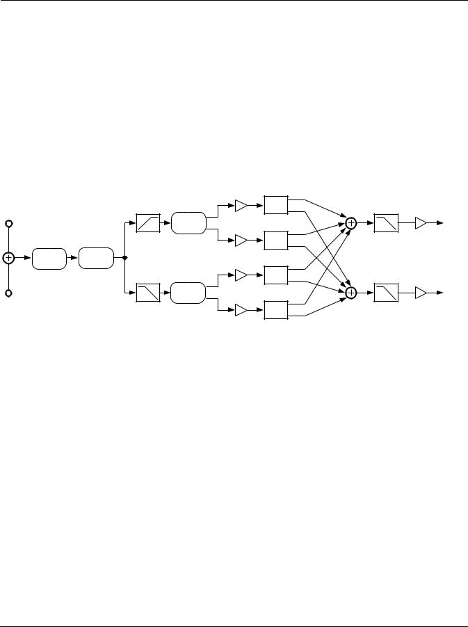
The KB3 FXBus and KB3 AuxFX algorithms contain multiple effects designed for the Hammond B3 emulation (KB3 mode). For correct operation, both effects must be running at the same time, with the output of KB3 FXBus feeding the input of KB3 AuxFX. The two algorithms work as one algorithm which use all the available KDFX resources.
While the input to KB3 FXBus is stereo (which gets summed to mono) and the output from KB3 AuxFX is stereo, the signals between the two algorithms are the low frequency (left) and high frequency (right) signal bands used to drive the lower and upper rotary speakers. It is possible to run these two algorithms as independent effects, but it is recommended.
These effects are the Hammond vibrato/chorus, amplifier distortion, and rotating speaker (Leslie) emulations. Each of these effects may be turned off or bypassed, or the entire algorithm may be bypassed. To bypass the rotary, the switches in both KB3 FXBus and KB3 AuxFX must be set to “Out”.
|
|
|
|
Hi Gain |
L Input |
|
|
|
L Output |
|
Vibrato/ |
Distortion |
Cabinet |
|
|
Chorus |
Filter |
Lo Gain |
|
|
|
|||
R Input |
|
|
|
R Output |
|
|
Block diagram of KB3 FXBus |
|
|
|
|
Pan |
|
|
L Input |
Rotator |
|
|
L Output |
|
|
Pan |
|
|
|
Mic Levels |
|
Out Gain |
|
|
|
Pan |
|
|
R Input |
Rotator |
|
|
R Output |


 Pan
Pan
Block diagram of KB3 AuxFX
The first effect in the chain is the Hammond vibrato/chorus algorithm. The vibrato/chorus has six settings which are the same as those used in the Hammond B3: three vibrato (V1, V2, V3) and three chorus (C1, C2, C3) settings. The vibrato chorus has been carefully modeled after the electro-mechanical vibrato/chorus in the B3.
An amplifier distortion algorithm follows the vibrato/chorus. For details, see the section in this book on FXAlg #723.
The distorted signal is next passed to a cabinet emulation filter and a pair of crossover filters for band splitting. The measurements of a real Leslie® speaker was used in the design of these filters. Default parameter values reflect these measurements, but you may alter them if you like. The Lo HP parameter controls a hipass filter which defines the lowest frequency to pass through the speaker. Likewise the Hi LP parameter is a lowpass filter controlling the
Algorithm Reference-113
FXAlg #735/6: KB3 FX
highest frequency. The crossover filters for the lower and upper drivers may be set independently. A small amount of overlap seems to work well. The gains of the high and low band signals may also be separately controlled.
At this point KB3 FXBus has finished its processing and passes the high and low signals to the KB3 AuxFX algorithm which contains the rotating-speaker routine. See the section in this book on FXAlg #733 for details.
Parameters (KB3 FXBus):
PAGE 1
|
In/Out |
In or Out |
Out Gain |
Off, -79.0 to 24.0 dB |
|
|
|
|
|
|
VibChInOut |
In or Out |
Dist Drive |
0 to 96 dB |
|
|
|
|
|
|
Vib/Chor |
V1 |
DistWarmth |
16 to 25088 Hz |
|
|
|
|
|
PAGE 2 |
|
|
|
|
|
|
|
|
|
|
RotoInOut |
In or Out |
|
|
|
|
|
|
|
|
Lo Gain |
Off, -79.0 to 24.0 dB |
Hi Gain |
Off, -79.0 to 24.0 dB |
|
|
|
|
|
|
Lo Xover |
16 to 25088 Hz |
Hi Xover |
16 to 25088 Hz |
|
|
|
|
|
|
Lo HP |
16 to 25088 Hz |
Hi LP |
16 to 25088 Hz |
|
|
|
|
|
In/Out |
When set to “In”, the algorithm is active; when set to “Out” the algorithm is bypassed. |
|
For the entire algorithm to be active, KB3 AuxFX must also be active. |
Out Gain |
The overall gain or amplitude at the output of the effect. For distortion, it is often |
|
necessary to turn the output gain down as the distortion drive is turned up. |
VibChInOut |
When set to “In” the vibrato/chorus is active; when set to “Out” the vibrato/chorus is |
|
bypassed. |
Vib/Chor |
This control sets the Hammond B3® vibrato/chorus. There are six settings for this effect: |
|
three vibratos “V1”, “V2”, “V3”, and three choruses “C1”, “C2”, “C3” |
Roto InOut |
When set to “In” the rotary speaker is active; when set to “Out” the rotary speaker is |
|
bypassed. By bypassing the rotary effect in KB3 FXBus, only the crossover filters are |
|
bypassed. You must also bypass KB3 AuxFX to completely bypass the rotary speakers. |
|
Likewise, for the entire rotary to be active, KB3 AuxFX must also be active. |
Dist Drive |
Applies a boost to the input signal to overdrive the distortion algorithm. When |
|
overdriven, the distortion algorithm will soft-clip the signal. Since distortion drive will |
|
make your signal very loud, you may have to reduce the Out Gain as the drive is |
|
increased. |
Warmth |
A lowpass filter in the distortion control path. This filter may be used to reduce some of |
|
the harshness of some distortion settings without reducing the bandwidth of the signal. |
Lo Gain |
The gain or amplitude of the signal passing through the rotating woofer (low frequency |
|
driver. The control is also available in KB3 AuxFX. |
Lo Xover |
The crossover frequency for the low frequency driver. Lo Xover controls a lowpass filter. |
Lo HP |
A hipass filter to simulate the band-limiting of a speaker cabinet. The filter controls the |
|
lower frequency limit of the output. |
Hi Gain |
The gain or amplitude of the signal passing through the rotating tweeter (high frequency |
|
driver. The control is also available in KB3 AuxFX. |
Hi Xover |
The crossover frequency for the high frequency driver. Hi Xover controls a hipass filter. |
Hi LP |
A lowpass filter to simulate the band-limiting of a speaker cabinet. The filter controls the |
|
upper frequency limit of the output. |
|
|
Algorithm Reference-114

FXAlg #735/6: KB3 FX
Parameters (KB3 AuxFX):
PAGE 1
|
In/Out |
In or Out |
Out Gain |
Off, -79.0 to 24.0 dB |
|
|
|
|
|
PAGE 2 |
|
|
|
|
|
|
|
|
|
|
Lo Gain |
Off, -79.0 to 24.0 dB |
Hi Gain |
Off, -79.0 to 24.0 dB |
|
|
|
|
|
|
Lo Rate |
-10.00 to 10.00 Hz |
Hi Rate |
-10.00 to 10.00 Hz |
|
|
|
|
|
|
Lo Size |
0 to 250 mm |
Hi Size |
0 to 250 mm |
|
|
|
|
|
|
Lo Trem |
0 to 100% |
Hi Trem |
0 to 100% |
|
|
|
|
|
|
Lo Beam W |
45.0 to 360.0 deg |
Hi Beam W |
45.0 to 360.0 deg |
|
|
|
|
|
PAGE 3 |
|
|
|
|
|
|
|
|
|
|
LoMicA Pos |
-180.0 to 180.0 deg |
LoMicB Pos |
-180.0 to 180.0 deg |
|
|
|
|
|
|
LoMicA Lvl |
0 to 100% |
LoMicB Lvl |
0 to 100% |
|
|
|
|
|
|
LoMicA Pan |
-100 to 100% |
LoMicB Pan |
-100 to 100% |
|
|
|
|
|
|
HiMicA Pos |
-180.0 to 180.0 deg |
HiMicB Pos |
-180.0 to 180.0 deg |
|
|
|
|
|
|
HiMicA Lvl |
0 to 100% |
HiMicB Lvl |
0 to 100% |
|
|
|
|
|
|
HiMicA Pan |
-100 to 100% |
HiMicB Pan |
-100 to 100% |
|
|
|
|
|
PAGE 4 |
|
|
|
|
|
|
|
|
|
|
LoResonate |
0 to 100% |
HiResonate |
0 to 100% |
|
|
|
|
|
|
Lo Res Dly |
10 to 2550 samp |
Hi Res Dly |
10 to 2550 samp |
|
|
|
|
|
|
LoResXcurs |
0 to 510 samp |
HiResXcurs |
0 to 510 samp |
|
|
|
|
|
|
ResH/LPhs |
0.0 to 360.0 deg |
|
|
|
|
|
|
|
In/Out |
When set to “In”, the algorithm is active; when set to “Off” the algorithm is bypassed. |
|
For the entire algorithm to be active, KB3 FXBus must also be active with its Roto InOut |
|
parameter set to “In”. To completely bypass the rotary, one or both of the In/Out or Roto |
|
InOut parameters in KB3 FXBus must also be bypassed. |
Out Gain |
The overall gain or amplitude at the output of the effect. |
Lo Gain |
The gain or amplitude of the signal passing through the rotating woofer (low frequency |
|
driver. The control is also available in KB3 FXBus. |
Hi Gain |
The gain or amplitude of the signal passing through the rotating tweeter (high frequency |
|
driver. The control is also available in KB3 FXBus. |
For details on the rest of the parameters see the section of this book on FXAlg #733.
Algorithm Reference-115
FXAlg #900: Env Follow Filt
FXAlg #900: Env Follow Filt
Envelope-following stereo 2-pole resonant filter
Allocation Units: 2
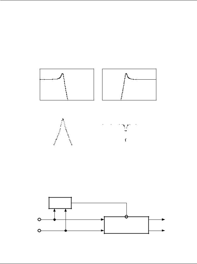
The envelope-following filter is a stereo resonant filter with the resonant frequency controlled by the envelope of the input signal (the maximum of left or right). The filter type is selectable and may be one of low pass (i), highpass (ii), band pass (iii), or notch (iv).
|
|
|
|
|
|
|
|
|
|
|
|
|
|
|
|
|
|
|
|
|
|
|
|
|
(i) |
|
|
|
|
|
|
|
|
|
|
|
|
(ii) |
|||||||||||||||||||||
|
|
|
|
|
|
|
|
|
|
|
|
|
|
|
|
|
|
|
|
|
|
|
|
|
|
|
|
|
|
|
|
|
|
|
|
|
|
|
|
|
|
|
|
|
|
|
|
|
|
|
|
|
|
|
|
|
|
|
|
|
|
|
|
|
|
|
|
|
|
|
|
|
|
|
|
|
|
|
|
|
|
|
|
|
|
|
|
|
|
|
|
|
|
|
|
|
|
|
|
|
|
|
|
|
|
|
|
|
|
|
|
|
|
|
|
|
|
|
|
(iii) |
(iv) |
Resonant Filter Types: (i) lowpass, (ii) highpass, (iii) bandpass, and (iv) notch.
The resonant frequency of the filter will remain at the minimum frequency (Min Freq) as long as the signal envelope is below the Threshold. The Freq Sweep parameter controls how much the frequency will change with changes in envelope amplitude. The frequency range is 0 to 8372 Hz, though the minimum setting for Min Freq is 16 Hz. Note that the term minimum frequency is a reference to the resonant frequency at the minimum envelope level; with a negative Freq Sweep, the filter frequency will sweep below the Min Freq. A meter is provided to show the current resonance frequency of the filter.
|
Envelope |
|
Follower |
L Input |
L Input |
|
Resonant Filter |
R Input |
R Input |
Block diagram of envelope-following filter
The filter Resonance level may be adjusted. The resonance is expressed in decibels (dB) of gain at the resonant frequency. Since 50 dB of gain is available, you will have to be careful with your gain stages to avoid clipping.
Algorithm Reference-116

FXAlg #900: Env Follow Filt
The attack and release rates of the envelope follower are adjustable. The rates are expressed in decibels per second (dB/s). The envelope may be smoothed by a lopass filter which can extend the attack and release times of the envelope follower. A level meter with a threshold marker is provided.
Parameters:
PAGE 1
|
Wet/Dry |
|
0 to 100%wet |
Out Gain |
|
Off, -79.0 to 24.0 dB |
|
|
|
|
|
|
|
|
|
||
|
FilterType |
Lowpass |
Min Freq |
|
16 to 8372 Hz |
|
||
|
|
|
|
|
|
|
|
|
|
F |
|
|
|
Freq Sweep |
|
-100 to 100% |
|
|
|
|
|
|
|
|
|
|
|
0Hz |
2k |
4k |
6k |
Resonance |
|
0 to 50 dB |
|
|
|
|
|
|
|
|
|
|
PAGE 2 |
|
|
|
|
|
|
|
|
|
|
|
|
|
|
|||
|
Threshold |
-79.0 to 0.0 dB |
Atk Rate |
|
0.0 to 300.0 dB/s |
|
||
|
|
|
|
|
|
|
|
|
|
|
|
|
|
Rel Rate |
|
0.0 to 300.0 dB/s |
|
|
|
|
|
|
|
|
|
|
|
|
|
|
|
Smth Rate |
|
0.0 to 300.0 dB/s |
|
|
|
|
|
|
|
|
|
|
|
|
|
|
|
E |
|
|
|
|
|
|
|
|
|
|
|
|
|
|
|
|
-dB 60 |
40 * 16 * 8 |
4 0 |
|
|
|
|
|
|
|
|
|||
Wet/Dry |
|
|
The amount of modulated (wet) signal relative to unaffected (dry) signal as a percent. |
|||||
Out Gain |
|
|
The overall gain or amplitude at the output of the effect. |
|||||
FilterType |
|
|
The type of resonant filter to be used. May be one of “Lowpass”, “Highpass”, |
|||||
|
|
|
|
“Bandpass”, or “Notch”. |
|
|
|
|
Min Freq |
|
|
The base frequency of the resonant filter. The filter resonant frequency is set to the Min |
|||||
|
|
|
|
Freq while the signal envelope is at its minimum level or below the threshold. |
||||
Freq Sweep |
|
How far the filter frequency can change from the Min Freq setting as the envelope |
||||||
|
|
|
|
amplitude changes. Freq Sweep may be positive or negative so the filter frequency can |
||||
|
|
|
|
rise above or fall below the Min Freq setting. |
||||
Resonance |
|
|
The resonance level of the resonant filter. Resonance sets the level of the resonant peak. |
|||||
|
|
|
|
In the notch filter, this sets the amount of cut, so 0 dB provides the highest, widest notch, |
||||
|
|
|
|
and higher levels make the notch increasingly narrower and shallower. |
||||
Threshold |
|
|
Represents the level above which signal envelope must rise before the filter begins to |
|||||
|
|
|
|
follow the envelope. Below the threshold, the filter resonant frequency will remain at the |
||||
|
|
|
|
Min frequency. |
|
|
|
|
Atk Rate |
|
|
Adjusts the upward slew rate of the envelope detector. |
|||||
Rel Rate |
|
|
Adjusts the downward slew rate of the envelope detector. |
|||||
Smth Rate |
|
|
Smooths the output of the envelope follower. Smoothing slows down the envelope |
|||||
|
|
|
|
follower and can dominate the attack and release rates if set to a lower rate than either of |
||||
|
|
|
|
these parameters. |
|
|
|
|
Algorithm Reference-117
FXAlg #901: TrigEnvelopeFilt
FXAlg #901: TrigEnvelopeFilt
Triggered envelope-following stereo 2-pole resonant filter
Allocation Units: 2
The triggered envelope-following filter is used to produce a filter sweep when the input rises above a trigger level. The triggered envelope-following filter is a stereo resonant filter with the resonant frequency controlled by a triggered envelope follower. The filter type is selectable and may be one of low pass (i), high pass (ii), band pass (iii), or notch (iv). See the previous section of this book, FXAlg #900, for diagrams of the filter actions.
|
|
Triggered |
Envelope |
Trigger |
Envelope |
Follower |
Generator |
Generator |
L Input |
|
L Input |
|
|
Resonant Filter |
R Input |
|
R Input |
Block diagram of Triggered Envelope Filter
The resonant frequency of the filter will remain at the minimum frequency (Min Freq) prior to being triggered. On a trigger, the resonant frequency will sweep to the maximum frequency (Max Freq). The minimum and maximum frequencies may be set to any combination of frequencies between 16 and 8372 Hz. Note that the terms minimum and maximum frequency are a reference to the resonant frequencies at the minimum and maximum envelope levels; you may set either of the frequencies to be larger than the other. A meter is provided to show the current resonance frequency of the filter.
The filter Resonance level may be adjusted. The resonance is expressed in decibels (dB) of gain at the resonant frequency. Since 50 dB of gain is available, you will have to be careful with your gain stages to avoid clipping.
When the input signal envelope rises above the trigger level, an envelope generator is started which has an instant attack and exponential decay. The generated attack may be lengthened with the smoothing parameter. The smoothing parameter can also lengthen the generated decay if the smoothing rate is lower than the decay. The generated envelope is then used to control the resonant frequency of the filter.
The time constant of the envelope follower may be set (Env Rate) as well as the decay rate of the generated envelope (Rel Rate). After the detected envelope rises above the Trigger level, a trigger event cannot occur again until the signal drops below the Retrigger level. In general, Retrigger should be set lower than the Trigger level. A level meter with a trigger marker is provided.
Parameters:
PAGE 1
|
Wet/Dry |
0 to 100%wet |
Out Gain |
Off, -79.0 to 24.0 dB |
|
|||
|
|
|
|
|
|
|
||
|
FilterType |
Lowpass |
Min Freq |
16 |
to 8372 Hz |
|
||
|
|
|
|
|
|
|
|
|
|
F |
|
|
|
Max Freq |
16 |
to 8372 Hz |
|
|
|
|
|
|
|
|
|
|
|
0Hz |
2k |
4k |
6k |
Resonance |
0 to 50 dB |
|
|
|
|
|
|
|
|
|
|
|
|
|
|
|
|
|
|
|
|
Algorithm Reference-118

|
|
|
|
|
FXAlg #901: TrigEnvelopeFilt |
|
PAGE 2 |
|
|
|
|
|
|
|
|
|
|
|
|
|
|
Trigger |
-79.0 to 0.0 dB |
Env Rate |
|
0.0 to 300.0 dB/s |
|
|
|
|
|
|
|
|
|
Retrigger |
-79.0 to 0.0 dB |
Rel Rate |
|
0.0 to 300.0 dB/s |
|
|
|
|
|
|
|
|
|
|
|
Smth Rate |
|
0.0 to 300.0 dB/s |
|
|
|
|
|
|
|
|
|
|
|
E |
|
|
|
|
|
|
|
|
|
|
|
|
-dB 60 |
40 * 16 * |
8 4 0 |
|
|
|
|
|
|
|
|
|
Wet/Dry |
The amount of modulated (wet) signal relative to unaffected (dry) signal as a percent. |
|||||
Out Gain |
The overall gain or amplitude at the output of the effect. |
|||||
FilterType |
The type of resonant filter to be used. May be one of “Lowpass”, “Highpass”, |
|||||
|
|
“Bandpass”, or “Notch”. |
|
|
|
|
Min Freq |
The base frequency of the resonant filter. The filter resonant frequency is set to the base |
|||||
|
|
frequency while the signal envelope is below the threshold. |
||||
Max Freq |
The frequency of the resonant filter that can be reached when the envelope follower |
|||||
|
|
output reaches full-scale. The resonant frequency will sweep with the envelope from the |
||||
|
|
base frequency, approaching the limit frequency with rising amplitudes. |
||||
Resonance |
The resonance level of the resonant filter. Resonance sets the level of the resonant peak. |
|||||
|
|
In the notch filter, this sets the amount of cut, so 0 dB provides the highest, widest notch, |
||||
|
|
and higher levels make the notch increasingly narrower and shallower. |
||||
Trigger |
The threshold at which the envelope detector triggers in fractions of full scale where 0dB |
|||||
|
|
is full scale. |
|
|
|
|
Retrigger |
The threshold at which the envelope detector resets such that it can trigger again in |
|||||
|
|
fractions of full scale where 0dB is full scale. This value is only useful when it is below |
||||
|
|
the value of Trigger. |
|
|
|
|
Env Rate |
The envelope detector decay rate which can be used to prevent false triggering. When |
|||||
|
|
the signal envelope falls below the retrigger level, the filter can be triggered again when |
||||
|
|
the signal rises above the trigger level. Since the input signal can fluctuate rapidly, it is |
||||
|
|
necessary to adjust the rate at which the signal envelope can fall to the retrigger level. |
||||
|
|
The rate is provided in decibels per second (dB/s). |
||||
Rel Rate |
The downward slew rate of the triggered envelope generator. The rate is provided in |
|||||
|
|
decibels per second (dB/s). |
|
|
|
|
Smth Rate |
Smooths the output of the envelope generator. Smoothing slows down the envelope |
|||||
|
|
follower and can dominate the release rate if set lower rate than this parameter. You can |
||||
|
|
use the smoothing rate to lengthen the attack of the generated envelope which would |
||||
|
|
otherwise have an instant attack. The rate is provided in decibels per second (dB/s) |
||||
Algorithm Reference-119
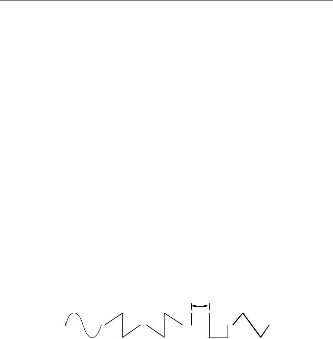
FXAlg #902: LFO Sweep Filter
FXAlg #902: LFO Sweep Filter
LFO-following stereo 2-pole resonant filter
Allocation Units: 2
The LFO following filter is a stereo resonant filter with the resonant frequency controlled by an LFO (low-frequency oscillator). The filter type is selectable and may be one of low pass (i), high pass (ii), band pass (iii), or notch (iv). See the section of this book on FXAlg #900 for diagrams of the filter actions.
The resonant frequency of the filter will sweep between the minimum frequency (Min Freq) and the maximum frequency (Max Freq). The minimum and maximum frequencies may be set to any combination of frequencies between 16 and 8372 Hz. Note that the terms minimum and maximum frequency are a reference to the resonant frequencies at the minimum and maximum envelope levels; you may set either of the frequencies to be larger than the other, though doing so will just invert the direction of the LFO. Meters are provided to show the current resonance frequencies of the left and right channel filters.
The filter Resonance level may be adjusted. The resonance is expressed in decibels (dB) of gain at the resonant frequency. Since 50 dB of gain is available, you will have to be careful with your gain stages to avoid clipping.
You can set the frequency of the LFO using the LFO Tempo and LFO Period controls. You can explicitly set the tempo or use the system tempo from the sequencer (or MIDI clock). The LFO Period control sets the period of the LFO (the time for one complete oscillation) in terms of the number of tempo beats per LFO period.
The LFO may be configured to one of a variety of wave shapes. Available shapes are Sine, Saw+, Saw-, Pulse and Tri. Sine is simply a sinusoid waveform. Tri produces a triangular waveform, and Pulse produces a series of square pulses where the pulse width can be adjusted with the “LFO PlsWid” parameter. When pulse width is 50%, the signal is a square wave. The “LFO PlsWid” parameter is only active when the Pulse waveform is selected. Saw+ and Sawproduce rising and falling sawtooth waveforms. The Pulse and Saw waveforms have abrupt, discontinuous changes in amplitude which can be smoothed. The pulse wave is implemented as a hard clipped sine wave, and, at 50% width, it turns into a sine wave when set to 100% smoothing. The sudden change in amplitude of the sawtooths develops a more gradual slope with smoothing, ending up as triangle waves when set to 100% smoothing.
PulseWidth
Sine |
Saw+ |
Saw- |
Pulse |
Tri |
Configurable Wave Shapes
Parameters:
PAGE 1
|
Wet/Dry |
0 to 100%wet |
Out Gain |
Off, -79.0 to 24.0 dB |
|
|
|
|
|
|
|
|
LFO Tempo |
System, 1 to 255 BPM |
LFO Shape |
Sine |
|
|
|
|
|
|
|
|
LFO Period |
1/24 to 32 bts |
LFO PlsWid |
0 to 100% |
|
|
|
|
|
|
|
|
|
|
LFO Smooth |
0 to 100% |
|
|
|
|
|
|
|
Algorithm Reference-120
Loading...