


Doc. No.
78-3816-01 Rev. A0
Catalyst 1800 Token Ring Switch Cable Kit Guide
This guide provides configuration and connection instructions for the EIA/TIA-232 console/modem
cable and the adapters used when connecting a PC, a VT series terminal, or a modem to the Catalyst
1800TokenRingswitch to access out-of-band management via theEIA/TIA-232 DB-9male console
port.
Note EIA/TIA-232 was known as recommended standard RS-232 before its acceptance as a
standard by the Electronic Industries Association (EIA) and Telecommunications Industry
Association (TIA).
Corporate Headquarters
Cisco Systems, Inc.
170 West Tasman Drive
San Jose, CA 95134-1706
USA
Copyright © 1996
Cisco Systems, Inc.
All rights reserved.
Cisco documentation and additional literature are available in a CD-ROM package. The
Documentation CD-ROM, a member of the Cisco Connection Family, is updated monthly.
Therefore, it might be more up to date than printed documentation. To order copies of the
Documentation CD-ROM, contact your local sales representative or call customer service. The
CD-ROMpackage is availableas a single package or as an annual subscription. Youcan also access
Cisco documentation on the World Wide Web at http://www.cisco.com,
http://www-china.cisco.com, or http://www-europe.cisco.com.
Management terminal and modem requirements are as follows:
• VT 320/420-series terminal or VT-type terminal running emulation programs for the VT series
• IBM or compatible PC running a VT-series emulation software package
• Hayes-compatible modem
This guide also provides the following pin assignments:
• DB-9 console port connector on the Catalyst 1800 chassis
• DB-9 PC connector
1

Connecting to a VT-Series Terminal
• DB-25 VT-series connector
• DB-25 modem connector
The Catalyst 1800 console cable kit (part number 78-1188-01) includes
• One 6-foot (1.8-meter) length of unshielded twisted pair (UTP) EIA/TIA-232 cable with RJ-45
connectors at each end
• One RJ-45 to DB-9 female adapter (for console port connection)
• One RJ-45 to DB-9 female adapter (for PC connection)
• One RJ-45 to DB-25 female adapter (for VT terminal connection)
• One RJ-45 to DB-25 male adapter (for modem connection)
Connecting to a VT-Series Terminal
Follow these steps to connect a VT 320/420-series terminal to a Catalyst 1800 Token Ring switch
(see Figure 1):
Step 1 Plug either end of the EIA/TIA-232 cable intothe RJ-45-to-DB-9 female adapter labelled
“Console port.”
Step 2 Connect the console port female adapter to the male DB-9 console port on the front of the
Catalyst 1800 chassis.
Step 3 Plug the RJ-45 connector at the other end of the EIA/TIA-232 cable into the
RJ-45-to-DB-25 female adapter labelled “VT series.”
Step 4 Connect the VT-series DB-25 female adapter to the DB-25 male adapter on the cable
extending from the VT terminal’s COMM port.
Step 5 Turnon the terminal and access the setup directory. Set the followingparameters on your
terminal:
Transmit 9600
Bits per character (BPC) 8
Parity None
Stop bit 1
Flow control Off
After these parameters are set, you can access out-of-band management. Refer to the Catalyst 1800
Token Ring Switch User Guide for instructions on using the console interface.
2 Catalyst 1800 Token Ring Switch Cable Kit Guide
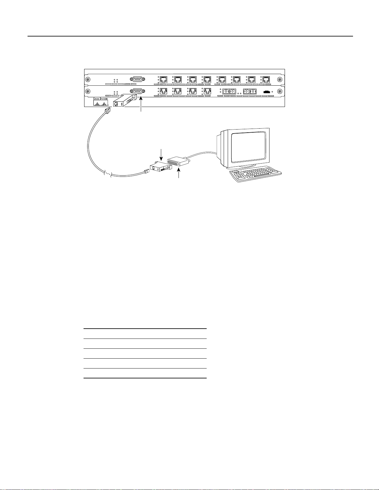
Connecting to an IBM PC or Compatible
Figure 1 Connecting a VT-Series Terminal to a Catalyst 1800 Switch
8
7
6
5
4
3
2
1
8 TOKEN RING
Pwr A
Sys Status
Pwr B
Failure
4TR + FDDI
Pwr A
Sys Status
Pwr B
Failure
connector/port interface
Ring Status
Port Activity
16 Mbps
1
Ring Status
Port Activity
16 Mbps
DB-9 console
2
Status
Activity
Wrap
A
B
Catalyst 1800
4
3
Bypass
H8710
RS-232 cable
VT series adapter
DB-25 male adapter
to VT terminal VT 320/340 series terminal
Connecting to an IBM PC or Compatible
Follow these steps to connect an IBM PC or compatible to a Catalyst 1800 switch (see Figure 2).
Note that the PC must be running a VT terminal emulation program.
Step 1 Plug either end of the EIA/TIA-232 cable intothe RJ-45-to-DB-9 female adapter labelled
“Console port.”
Step 2 Connect the console port female adapter to the male DB-9 console port on the front of the
Catalyst 1800 chassis.
Step 3 Plug the RJ-45 connector at the other end of the EIA/TIA-232 cable into the
RJ-45-to-DB-9 female adapter labelled “PC.”
Step 4 Connect the DB-9 female adapter to the appropriate male communications port on the
PC.
Step 5 Turn on the PC and configure its VT emulation package with following parameters:
Transmit 9600
Bits per character (BPC) 8
Parity None
Stop bit 1
Flow control Off
After these parameters are set, you can access out-of-band management. Refer to the Catalyst 1800
Token Ring Switch User Guide for instructions on using the console interface.
Catalyst 1800 Token Ring Switch Cable Kit Guide 3

Connecting to a Modem
Figure 2 Connecting an IBM PC or Compatible to a Catalyst 1800 Switch
8 TOKEN RING
Pwr A
Sys Status
Pwr B
Failure
4TR + FDDI
Pwr A
Sys Status
Pwr B
Failure
connector/port interface
RS-232 cable
Ring Status
Port Activity
16 Mbps
Ring Status
Port Activity
16 Mbps
DB-9 console
RJ-45 port
connectors
1
1
8
7
6
5
4
3
2
4
3
2
Status
Activity
Wrap
A
B
Catalyst 1800
Bypass
H8711
Port status
LEDs
Connecting to a Modem
Follow these steps to connect an IBM PC or compatible to a Catalyst 1800 switch (see Figure 3).
Note that the PC must be running a VT terminal emulation program.
Step 1 Plug either end of the EIA/TIA-232 cable intothe RJ-45-to-DB-9 female adapter labelled
“Console port.”
Step 2 Connect the console port female adapter to the male DB-9 console port on the front of the
Catalyst 1800 chassis.
Step 3 Plug the RJ-45 connector at the other end of the EIA/TIA-232 cable into the
RJ-45-to-DB-25 male adapter labelled “Modem.”
Step 4 Connect the DB-25 male adapter to the appropriate female communications port on the
modem.
Step 5 Turnon the modem and configure its VT emulation package with following parameters:
Transmit 9600
Bits per character (BPC) 8
Parity None
Stop bit 1
Flow control Off
PC adapter
PC or compatible
After these parameters are set, you can access out-of-band management. Refer to the Catalyst 1800
Token Ring Switch User Guide for instructions on using the console interface.
4 Catalyst 1800 Token Ring Switch Cable Kit Guide

Wiring and Signal Assignment Specifications
Figure 3 Connecting a Modem to a Catalyst 1800 Switch
RJ-45 port
connectors
6
5
4
3
2
1
8 TOKEN RING
Pwr A
Sys Status
Pwr B
Failure
4TR + FDDI
Pwr A
Sys Status
Pwr B
Failure
connector/port interface
RS-232 cable
Ring Status
Port Activity
16 Mbps
Ring Status
Port Activity
16 Mbps
DB-9 console
2
1
Modem adapter
3
Port status
LEDs
4
Status
Activity
7
Wrap
A
B
Catalyst 1800
8
Bypass
H9224
Modem
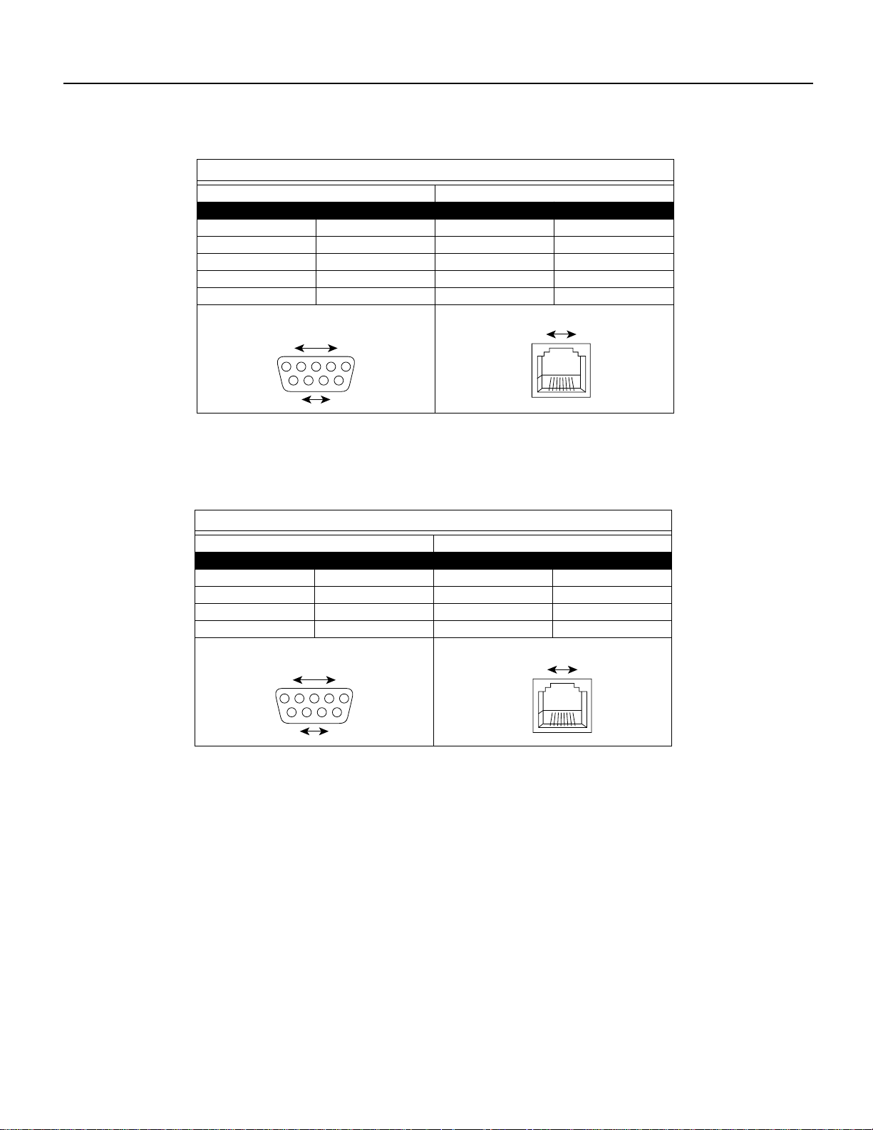
Wiring and Signal Assignment Specifications
Diagrams in this section provide wiring and signal information for the cable and adapters in the
Catalyst 1800 console cable kit.
RJ-45 cable wiring diagram
End 1
Pin
1
2
3
4
5
6
7
8
RJ-45 connector
end 1
Pins
1
Conductor
White/Orange
Orange/White
White/Green
Blue/White
White/Blue
Green/White
White/Brown
Brown/White
8
Male
Pin
Pin
1
1
2
2
3
3
4
4
5
5
6
6
7
7
8
8
RJ-45 connector
end 2
Pins
End 2
1
Conductor
White/Orange
Orange/White
White/Green
Blue/White
White/Blue
Green/White
White/Brown
Brown/White
8
Male
H8712
Catalyst 1800 Token Ring Switch Cable Kit Guide 5
Wiring and Signal Assignment Specifications
Console port adapter wiring & signal diagram
DB-9
Pin
2
3
4
5
7
DB-9 connector
Female
Signal
RD
TD
DTR
GND
RTS
Pins
5
96
RJ-45
Pin
4
1
8
5
6
RJ-45 port
Pins
8
Conductor
Red
Blue
White
Green
Yellow
1
1
Female
H8713
Pin
1
2
3
5
DB-9 connector
Female
PC adapter wiring & signal diagram
DB-9
Signal
DCD
RD
TD
GND
Pins
5
1
96
Pin
6
1
4
5
RJ-45 port
Female
RJ-45
Pins
8
Conductor
Yellow
Blue
Red
Green
1
H8714
6 Catalyst 1800 Token Ring Switch Cable Kit Guide
20
2
3
4
7
Pin
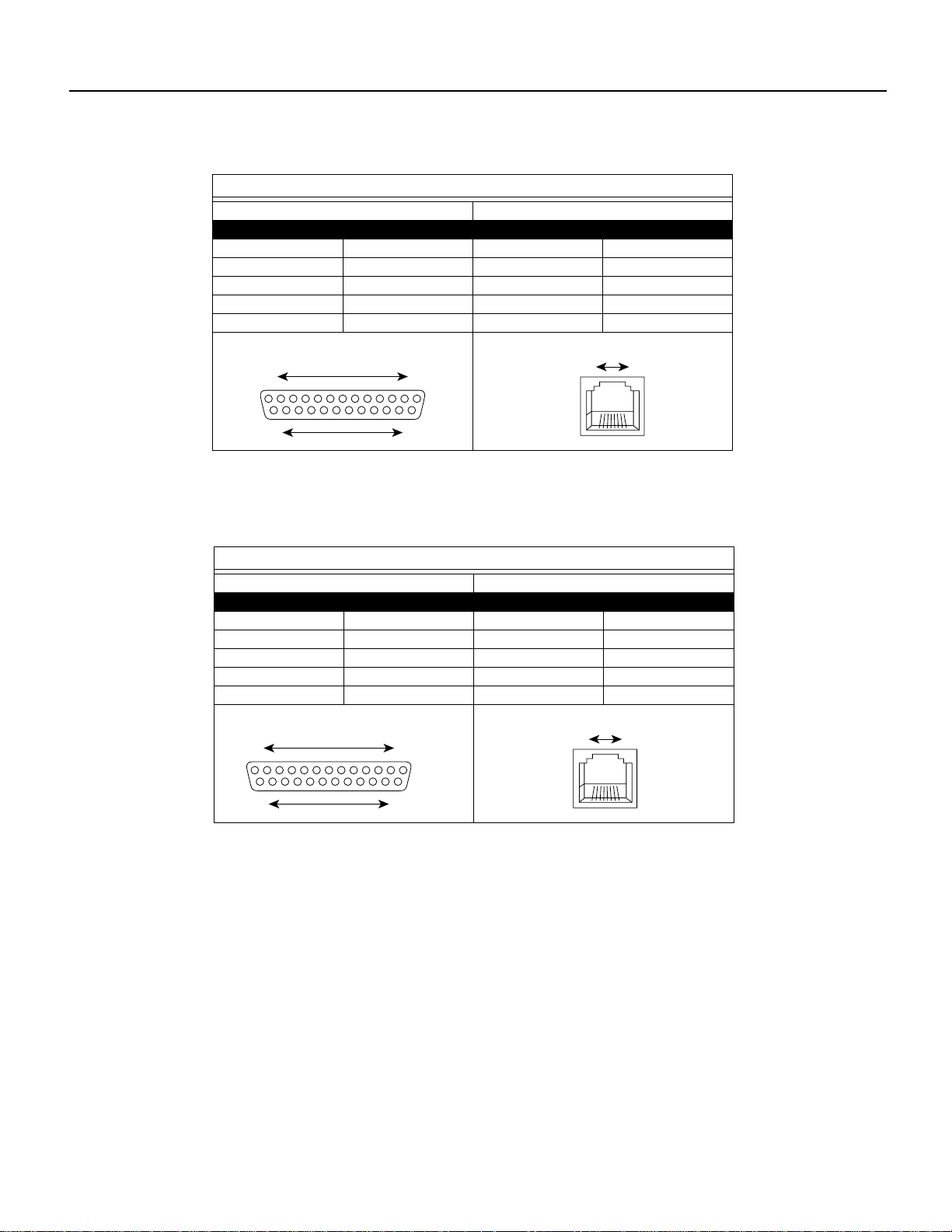
Modem adapter wiring & signal diagram
DB-25
Signal
TD
RD
RTS
GND
DTR
Pin
4
1
8
5
6
Cisco Connection Online
RJ-45
DB-25 connector
1 13
14 25
Pin
2
3
4
7
20
DB-25 connector
Pins
Pins
Male
VT series adapter wiring & signal diagram
DB-25
Signal
TD
RD
CTS
GND
DTR
113
Female
1425
RJ-45 port
Pin
4
1
8
5
6
RJ-45 port
Female
Female
Pins
8
RJ-45
Pins
8
1
H8715
Conductor
Red
Blue
Yellow
Green
White
1
H8716
Cisco Connection Online
CiscoConnection Online (CCO) is CiscoSystems’ primary,real-timesupport channel. Maintenance
customers and partners can self-register on CCO to obtain additional information and services.
Available 24 hours a day, 7 days a week, CCO provides a wealth of standard and value-added
services to Cisco’scustomers andbusiness partners.CCO services includeproduct information, user
documentation, software updates, release notes, technical tips, the Bug Navigator, configuration
notes, brochures, descriptions of service offerings, and download access to public and authorized
files.
CCO serves a wide variety of users through two interfaces that are updated and enhanced
simultaneously: a character-based version and a multimedia version that resides on the WorldWide
Web (WWW). The character-based CCO supports Zmodem, Kermit, Xmodem, FTP, and Internet
Catalyst 1800 Token Ring Switch Cable Kit Guide 7

Cisco Connection Online
e-mail,and it isexcellent forquick access to information overlowerbandwidths. The WWWversion
of CCO provides richly formatted documents with photographs,figures, graphics, and video,as well
as hyperlinks to related information.
You can access CCO in the following ways:
• WWW: http://www.cisco.com
• WWW: http://www-europe.cisco.com
• WWW: http://www-china.cisco.com
• Telnet: cco.cisco.com
• Modem: From North America, 408 526-8070; from Europe, 33 1 64 46 40 82. Use the
For a copy of CCO’s Frequently Asked Questions (FAQ), contact cco-help@cisco.com. For
additional information, contact cco-team@cisco.com.
Note If you are a network administrator and need personal technical assistance with a Cisco
product that is under warranty or covered by a maintenance contract, contact Cisco’s Technical
Assistance Center (TAC) at 800 553-2447, 408 526-7209, or tac@cisco.com. To obtain general
information about Cisco Systems, Cisco products, or upgrades, contact 800 553-6387,
408 526-7208, or cs-rep@cisco.com.
following terminal settings: VT100 emulation; databits: 8; parity: none; stop bits: 1; and
connection rates up to 28.8 kbps.
This document is to be used in conjunction with the Catalyst 1800 Token Ring Switch User Guide publication.
AtmDirector, AutoConnect, AutoRoute, AXIS, BPX, Catalyst, CD-PAC, CiscoAdvantage, CiscoFusion, Cisco IOS, the Cisco IOS logo, CiscoLink, CiscoPro, the CiscoPro logo,
CiscoRemote, the CiscoRemote logo, CiscoSecure, Cisco Systems, CiscoView, CiscoVision, CiscoWorks, ClickStart, ControlStream, EdgeConnect, EtherChannel, FairShare, FastCell,
FastForward, FastManager, FastMate, FastPADlmp, FastPADmicro, FastPADmp, FragmentFree, FrameClass, Fulcrum INS, IGX, Impact, InternetJunction, JumpStart, LAN
Enterprise, LAN
StrataSphere, StrataSphere BILLder,StrataSphereConnection Manager,StrataSphereModeler,StrataSphereOptimizer,Stratm,StrataView Plus, StreamView,SwitchProbe,SwitchVision,
SwitchWare, SynchroniCD,The Cell, The FastPacket Company, TokenSwitch, TrafficDirector, Virtual EtherSwitch, VirtualStream, VlanDirector, Web Clusters, WNIC, Workgroup
Director, Workgroup Stack, and XCI are trademarks; Access by Cisco, Bringing the Power of Internetworking to Everyone, Enter the Net with MultiNet, and The Network Works.
No Excuses. are service marks; and Cisco, the Cisco Systems logo, CollisionFree, Combinet, EtherSwitch, FastHub, FastLink, FastNIC, FastPacket, FastPAD, FastSwitch, ForeSight,
Grand, Grand Junction, Grand Junction Networks, the Grand Junction Networks logo, HSSI, IGRP, IPX, Kalpana, the Kalpana logo, LightStream, MultiNet, MultiWare, OptiClass,
Personal Ethernet, Phase/IP, RPS, StrataCom, TGV, the TGV logo, and UniverCD are registered trademarks of Cisco Systems, Inc. All other trademarks, service marks, registered
trademarks, or registered service marks mentioned in this document are the property of their respective owners.
Copyright © 1996, Cisco Systems, Inc.
All rights reserved. Printed in USA.
969R
8 Catalyst 1800 Token Ring Switch Cable Kit Guide
2
LAN Remote Office, LightSwitch, NetBeyond, NetFlow,Newport Systems Solutions, Packet, PIX, Point and Click Internetworking,RouteStream,Secure/IP,SMARTnet,
2
LAN
 Loading...