

Page 1

P-320W v3
802.11g Wireless Firewall Router
Default Login Details
IP Address http://192.168.1.1
Password 1234
Firmware Version 1.0
Edition 1, 3/2009
www.zyxel.com
www.zyxel.com
Copyright © 2009
ZyXEL Communications Corporation
Page 2

Page 3

About This User's Guide
About This User's Guide
Intended Audience
This manual is intended for people who want to configure the P-320W v3 using the
web configurator. You should have at least a basic knowledge of TCP/IP
networking concepts and topology.
Related Documentation
•Quick Start Guide
The Quick Start Guide is designed to help you get up and running right away. It
contains information on setting up your network and configuring for Internet
access.
• Supporting Disc
Refer to the included CD for support documents.
• ZyXEL Web Site
Please refer to www.zyxel.com
product certifications.
for additional support documentation and
User Guide Feedback
Help us help you. Send all User Guide-related comments, questions or suggestions
for improvement to the following address, or use e-mail instead. Thank you!
The Technical Writing Team,
ZyXEL Communications Corp.,
6 Innovation Road II,
Science-Based Industrial Park,
Hsinchu, 300, Taiwan.
E-mail: techwriters@zyxel.com.tw
P-320W v3 User’s Guide
3
Page 4

About This User's Guide
Customer Support
In the event of problems that cannot be solved by using this manual, you should
contact your vendor. If you cannot contact your vendor, then contact a ZyXEL
office for the region in which you bought the device. See http://www.zyxel.com/
web/contact_us.php for contact information. Please have the following information
ready when you contact an office.
• Product model and serial number.
•Warranty Information.
• Date that you received your device.
Brief description of the problem and the steps you took to solve it.
4
P-320W v3 User’s Guide
Page 5

Document Conventions
Document Conventions
Warnings and Notes
These are how warnings and notes are shown in this User’s Guide.
Warnings tell you about things that could harm you or your device.
Note: Notes tell you other important information (for example, other things you may
need to configure or helpful tips) or recommendations.
Syntax Conventions
• The P-320W v3 may be referred to as the “P-320W v3”, the “device”, the
“product” or the “system” in this User’s Guide.
• Product labels, screen names, field labels and field choices are all in bold font.
• A key stroke is denoted by square brackets and uppercase text, for example,
[ENTER] means the “enter” or “return” key on your keyboard.
• “Enter” means for you to type one or more characters and then press the
[ENTER] key. “Select” or “choose” means for you to use one of the predefined
choices.
• A right angle bracket ( > ) within a screen name denotes a mouse click. For
example, Maintenance > Log > Log Setting means you first click
Maintenance in the navigation panel, then the Log sub menu and finally the
Log Setting tab to get to that screen.
• Units of measurement may denote the “metric” value or the “scientific” value.
For example, “k” for kilo may denote “1000” or “1024”, “M” for mega may
denote “1000000” or “1048576” and so on.
• “e.g.,” is a shorthand for “for instance”, and “i.e.,” means “that is” or “in other
words”.
P-320W v3 User’s Guide
5
Page 6
Document Conventions
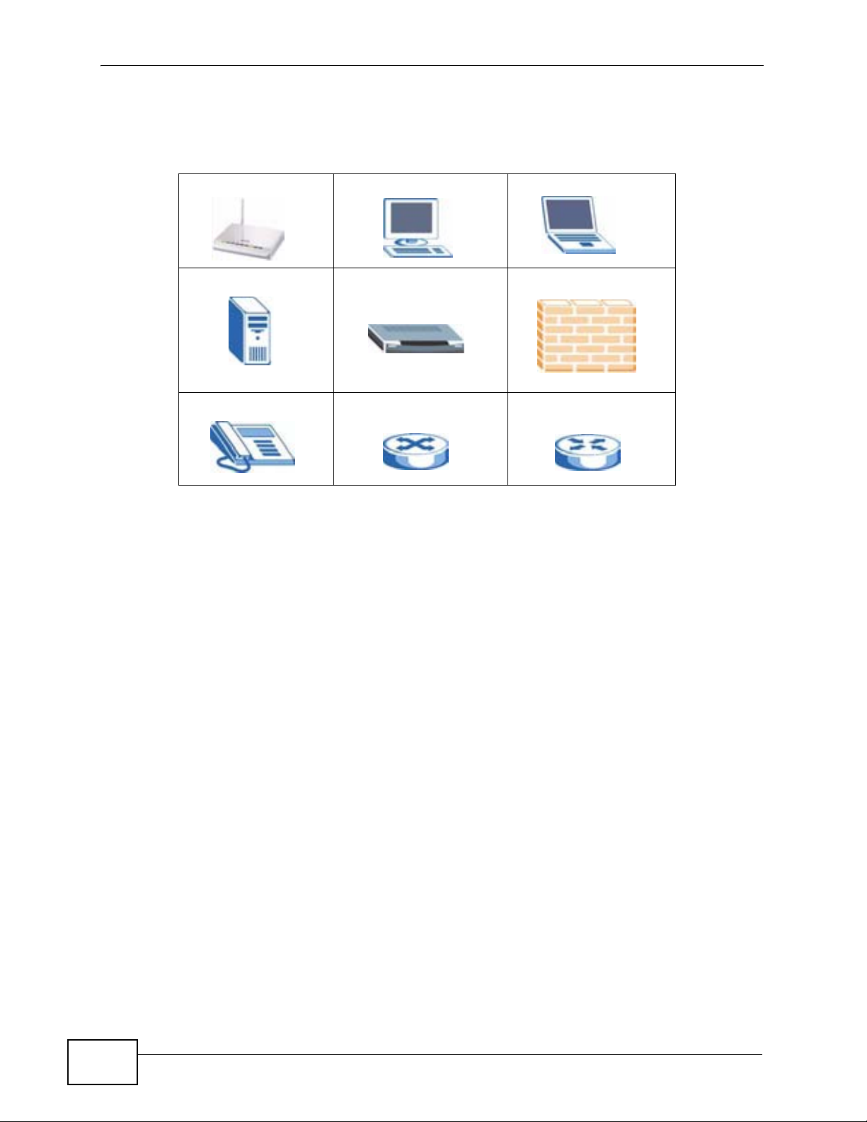
Icons Used in Figures
Figures in this User’s Guide may use the following generic icons.
P-320W v3 Computer Notebook computer
Server Modem Firewall
Tele p ho n e Switch Router
6
P-320W v3 User’s Guide
Page 7

Safety Warnings
Safety Warnings
• Do NOT use this product near water, for example, in a wet basement or near a swimming
pool.
• Do NOT expose your device to dampness, dust or corrosive liquids.
• Do NOT store things on the device.
• Do NOT install, use, or service this device during a thunderstorm. There is a remote risk
of electric shock from lightning.
• Connect ONLY suitable accessories to the device.
• Do NOT open the device or unit. Opening or removing covers can expose you to
dangerous high voltage points or other risks. ONLY qualified service personnel should
service or disassemble this device. Please contact your vendor for further information.
• Make sure to connect the cables to the correct ports.
• Place connecting cables carefully so that no one will step on them or stumble over them.
• Always disconnect all cables from this device before servicing or disassembling.
• Use ONLY an appropriate power adaptor or cord for your device.
• Connect the power adaptor or cord to the right supply voltage (for example, 110V AC in
North America or 230V AC in Europe).
• Do NOT allow anything to rest on the power adaptor or cord and do NOT place the
product where anyone can walk on the power adaptor or cord.
• Do NOT use the device if the power adaptor or cord is damaged as it might cause
electrocution.
• If the power adaptor or cord is damaged, remove it from the power outlet.
• Do NOT attempt to repair the power adaptor or cord. Contact your local vendor to order a
new one.
• Do not use the device outside, and make sure all the connections are indoors. There is a
remote risk of electric shock from lightning.
• Do NOT obstruct the device ventilation slots, as insufficient airflow may harm your
device.
• Antenna Warning! This device meets ETSI and FCC certification requirements when using
the included antenna(s). Only use the included antenna(s).
• If you wall mount your device, make sure that no electrical lines, gas or water pipes will
be damaged.
Your product is marked with this symbol, which is known as the WEEE mark. WEEE
stands for Waste Electronics and Electrical Equipment. It means that used electrical
and electronic products should not be mixed with general waste. Used electrical and
electronic equipment should be treated separately.
P-320W v3 User’s Guide
7
Page 8

Safety Warnings
8
P-320W v3 User’s Guide
Page 9

Contents Overview
Contents Overview
Introduction ............................................................................................................................ 19
Getting to Know Your P-320W v3 .............................................................................................. 21
Introducing the Web Configurator .............................................................................................. 25
Connection Wizard .................................................................................................................... 37
Network ................................................................................................................................... 53
Wireless LAN ............................................................................................................................. 55
Wireless Client Mode ................................................................................................................. 73
Wireless Tutorial ........................................................................................................................ 77
LAN ............................................................................................................................................ 85
DHCP Server ............................................................................................................................. 89
Network Address Translation (NAT) .......................................................................................... 93
VLAN ....................................................................................................................................... 101
Security ................................................................................................................................. 105
WAN ........................................................................................................................................ 107
Firewall .....................................................................................................................................117
Content Filtering ...................................................................................................................... 125
Management ......................................................................................................................... 129
Static Route ............................................................................................................................. 131
Remote Management ..............................................................................................................135
Universal Plug-and-Play (UPnP) ............................................................................................. 141
Maintenance and Troubleshooting .....................................................................................155
System ..................................................................................................................................... 157
Logs ......................................................................................................................................... 163
Tools ........................................................................................................................................ 179
Troubleshooting ....................................................................................................................... 185
Product Specifications ............................................................................................................. 193
Appendices and Index ......................................................................................................... 197
P-320W v3 User’s Guide
9
Page 10

Contents Overview
10
P-320W v3 User’s Guide
Page 11

Table of Contents
Table of Contents
About This User's Guide ..........................................................................................................3
Document Conventions............................................................................................................5
Safety Warnings........................................................................................................................ 7
Contents Overview ...................................................................................................................9
Table of Contents.................................................................................................................... 11
Part I: Introduction................................................................................. 19
Chapter 1
Getting to Know Your P-320W v3 .......................................................................................... 21
1.1 Overview .............................................................................................................................. 21
1.2 Ways to Manage the P-320W v3 ......................................................................................... 22
1.3 Good Habits for Managing the P-320W v3 .......................................................................... 22
1.4 LEDs .................................................................................................................................... 23
Chapter 2
Introducing the Web Configurator ........................................................................................ 25
2.1 Web Configurator Overview ................................................................................................. 25
2.2 Accessing the Web Configurator ......................................................................................... 25
2.3 Resetting the P-320W v3 ..................................................................................................... 27
2.3.1 Procedure to Use the Reset Button ........................................................................... 27
2.4 Navigating the Web Configurator ...................................................................................... 27
2.4.1 Navigation Panel ........................................................................................................ 30
2.4.2 Summary: DHCP Table ............................................................................................ 32
2.4.3 Summary: Association List ...................................................................................... 33
2.4.4 Summary: Statistics ................................................................................................. 33
2.4.5 Summary: Active Session ...................................................................................... 34
2.4.6 Summary: Routing Table ............................................................................................ 35
Chapter 3
Connection Wizard .................................................................................................................37
3.1 Wizard Setup ....................................................................................................................... 37
3.2 Connection Wizard: STEP 1: System Information ............................................................... 38
3.2.1 System Name ............................................................................................................. 38
P-320W v3 User’s Guide
11
Page 12

Table of Contents
3.2.2 Domain Name ............................................................................................................ 38
3.3 Connection Wizard: STEP 2: Wireless LAN ........................................................................ 40
3.3.1 Basic(WEP) Security .................................................................................................. 42
3.3.2 Extend (WPA-PSK) Security ...................................................................................... 43
3.4 Connection Wizard: STEP 3: Internet Configuration ........................................................... 43
3.4.1 Ethernet Connection .................................................................................................. 44
3.4.2 PPPoE Connection .................................................................................................... 44
3.4.3 PPTP Connection ....................................................................................................... 46
3.4.4 Your IP Address ......................................................................................................... 47
3.4.5 WAN IP Address Assignment ..................................................................................... 48
3.4.6 IP Address and Subnet Mask ..................................................................................... 48
3.4.7 DNS Server Address Assignment .............................................................................. 49
3.4.8 WAN IP and DNS Server Address Assignment ......................................................... 50
3.4.9 WAN MAC Address .................................................................................................... 51
3.5 Connection Wizard Complete .............................................................................................. 52
Part II: Network....................................................................................... 53
Chapter 4
Wireless LAN...........................................................................................................................55
4.1 Overview .............................................................................................................................. 55
4.2 What You Can Do ................................................................................................................ 56
4.3 What You Need To Know ..................................................................................................... 56
4.3.1 SSID ........................................................................................................................... 56
4.3.2 MAC Address Filter .................................................................................................... 57
4.3.3 User Authentication .................................................................................................... 57
4.3.4 Encryption .................................................................................................................. 58
4.3.5 WiFi Protected Setup ................................................................................................. 60
4.4 General Wireless LAN Screen ............................................................................................ 60
4.4.1 No Security ................................................................................................................. 62
4.4.2 WEP Encryption ......................................................................................................... 63
4.4.3 WPA-PSK ................................................................................................................... 64
4.4.4 WPA ........................................................................................................................... 65
4.4.5 802.1x + Dynamic WEP ............................................................................................. 66
4.4.6 WPA-PSK/WPA2-PSK (Mixed) ................................................................................... 67
4.5 MAC Filter ............................................................................................................................ 68
4.6 WPS Screen ........................................................................................................................ 69
4.7 WPS Station Screen ............................................................................................................ 70
4.8 Wireless LAN Advanced Screen ......................................................................................... 70
Chapter 5
Wireless Client Mode.............................................................................................................. 73
12
P-320W v3 User’s Guide
Page 13

Table of Contents
5.1 Overview .............................................................................................................................. 73
5.2 What You Can Do ................................................................................................................ 73
5.3 Wireless Client Mode Screen .............................................................................................. 74
Chapter 6
Wireless Tutorial .....................................................................................................................77
6.1 How to Connect to the Internet from an AP ......................................................................... 77
6.2 Configure Wireless Security Using WPS on both your P-320W v3 and Wireless Client ..... 77
6.2.1 Push Button Configuration (PBC) .............................................................................. 78
6.2.2 PIN Configuration ....................................................................................................... 79
6.3 Enable and Configure Wireless Security without WPS on your P-320W v3 ........................ 81
6.4 Configure Your Notebook ....................................................................................................82
Chapter 7
LAN........................................................................................................................................... 85
7.1 Overview .............................................................................................................................. 85
7.2 What You Can Do ................................................................................................................ 85
7.3 What You Need to Know ......................................................................................................85
7.3.1 IP Pool Setup ............................................................................................................. 86
7.3.2 System DNS Servers ................................................................................................. 86
7.3.3 LAN TCP/IP ................................................................................................................ 86
7.3.4 Factory LAN Defaults ................................................................................................. 86
7.3.5 IP Address and Subnet Mask ..................................................................................... 86
7.4 LAN IP Screen ..................................................................................................................... 87
Chapter 8
DHCP Server............................................................................................................................89
8.1 Overview .............................................................................................................................. 89
8.2 What You Can Do ................................................................................................................ 89
8.3 DHCP Server General Screen ............................................................................................. 89
8.4 Static DHCP Screen ......................................................................................................... 91
8.5 Client List Screen ................................................................................................................ 91
Chapter 9
Network Address Translation (NAT)......................................................................................93
9.1 Overview ........................................................................................................................... 93
9.2 What You Can Do ................................................................................................................ 93
9.3 What You Need to Know ......................................................................................................93
9.3.1 Port Forwarding: Services and Port Numbers ............................................................ 94
9.3.2 Trigger Port Forwarding ............................................................................................. 95
9.3.3 Two Points To Remember About Trigger Ports .......................................................... 96
9.4 General NAT Screen ............................................................................................................ 96
9.5 Port Forwarding Screen ..................................................................................................... 97
P-320W v3 User’s Guide
13
Page 14

Table of Contents
9.5.1 Rule Setup Screen ..................................................................................................... 98
9.6 Trigger Port Screen ............................................................................................................. 99
9.7 Technical Reference .......................................................................................................... 100
9.7.1 Game List Example .................................................................................................. 100
Chapter 10
VLAN ......................................................................................................................................101
10.1 Overview ..................................................................................................................... 101
10.2 What You Can Do ............................................................................................................ 101
10.3 What You Need to Know .................................................................................................. 102
10.3.1 How VLAN Works .................................................................................................. 102
10.3.2 VLAN Tag ............................................................................................................... 102
10.4 VLAN Screen ................................................................................................................... 102
Part III: Security.................................................................................... 105
Chapter 11
WAN........................................................................................................................................107
11.1 Overview .......................................................................................................................... 107
11.2 What You Can Do ............................................................................................................ 107
11.3 Internet Connection Screen ............................................................................................. 108
11.3.1 Ethernet Encapsulation .......................................................................................... 108
11.3.2 PPPoE Encapsulation ............................................................................................ 109
11.3.3 PPTP Encapsulation ................................................................................................ 111
11.4 Advanced Screen ..............................................................................................................114
11.5 Traffic Redirect Screen .....................................................................................................114
Chapter 12
Firewall................................................................................................................................... 117
12.1 Overview .........................................................................................................................117
12.2 What You Can Do .............................................................................................................117
12.3 What You Need to Know ...................................................................................................117
12.3.1 About the P-320W v3 Firewall .................................................................................118
12.3.2 Security Parameter Index (SPI) ..............................................................................118
12.4 General Firewall Screen ................................................................................................119
12.5 Services Screen ...............................................................................................................119
12.6 Technical Reference ........................................................................................................ 121
12.6.1 Guidelines For Enhancing Security With Your Firewall .......................................... 121
12.6.2 Services ................................................................................................................. 122
Chapter 13
Content Filtering ...................................................................................................................125
14
P-320W v3 User’s Guide
Page 15

Table of Contents
13.1 Overview .......................................................................................................................... 125
13.2 What You Can Do ............................................................................................................ 125
13.3 Filter Screen .................................................................................................................... 125
13.4 Technical Reference ........................................................................................................ 127
13.4.1 Domain Name or IP Address URL Checking ......................................................... 127
13.4.2 Full Path URL Checking ......................................................................................... 127
13.4.3 File Name URL Checking ....................................................................................... 128
Part IV: Management............................................................................ 129
Chapter 14
Static Route ...........................................................................................................................131
14.1 Overview .......................................................................................................................... 131
14.2 What You Can Do ............................................................................................................ 132
14.3 IP Static Route Screen ....................................................................................................132
14.3.1 Static Route Setup Screen ................................................................................... 133
Chapter 15
Remote Management............................................................................................................ 135
15.1 Overview .......................................................................................................................... 135
15.2 What You Can Do ............................................................................................................ 136
15.3 What You Need to Know .................................................................................................. 136
15.3.1 Remote Management Limitations .......................................................................... 136
15.3.2 Remote Management and NAT .............................................................................. 136
15.3.3 System Timeout .................................................................................................... 136
15.4 WWW Screen ................................................................................................................ 137
15.5 The SNMP Screen ...........................................................................................................138
15.6 Security Screen ............................................................................................................. 139
Chapter 16
Universal Plug-and-Play (UPnP).......................................................................................... 141
16.1 Overview .......................................................................................................................... 141
16.2 What You Can Do ............................................................................................................ 141
16.3 What You Need to Know .................................................................................................. 141
16.3.1 How do I know if I'm using UPnP? ......................................................................... 141
16.3.2 NAT Traversal ........................................................................................................ 142
16.3.3 Cautions with UPnP ............................................................................................... 142
16.3.4 UPnP and ZyXEL ................................................................................................... 142
16.4 UPnP Screen ................................................................................................................... 143
16.5 Technical Reference ........................................................................................................ 143
16.5.1 Installing UPnP in Windows Example .................................................................... 143
P-320W v3 User’s Guide
15
Page 16

Table of Contents
Part V: Maintenance and Troubleshooting ........................................ 155
Chapter 17
System ...................................................................................................................................157
17.1 Overview .......................................................................................................................... 157
17.2 What You Can Do ............................................................................................................ 157
17.3 What You Need to Know .................................................................................................. 157
17.3.1 Dynamic DNS Introduction .................................................................................... 157
17.3.2 DynDNS Wildcard .................................................................................................. 158
17.4 System General Screen ................................................................................................. 158
17.5 Dynamic DNS Screen .................................................................................................... 160
17.6 Time Setting Screen ........................................................................................................ 161
Chapter 18
Logs .......................................................................................................................................163
18.1 Overview .......................................................................................................................... 163
18.2 What You Can Do ............................................................................................................ 163
18.3 What You Need to Know .................................................................................................. 163
18.4 View Log Screen .............................................................................................................. 164
18.5 Log Settings Screen ........................................................................................................ 165
18.6 Technical Reference ........................................................................................................ 166
18.6.1 Log Descriptions .................................................................................................... 166
Chapter 19
Tools....................................................................................................................................... 179
19.1 Overview .......................................................................................................................... 179
19.2 What You Can Do ............................................................................................................ 179
19.3 Firmware Upload Screen ................................................................................................. 179
19.4 Configuration Screen ....................................................................................................... 181
19.4.1 Backup Configuration ............................................................................................. 181
19.4.2 Restore Configuration ............................................................................................ 182
19.4.3 Back to Factory Defaults ........................................................................................ 183
19.5 Restart Screen ................................................................................................................. 183
Chapter 20
Troubleshooting ....................................................................................................................185
20.1 Power, Hardware Connections, and LEDs ...................................................................... 185
20.2 P-320W v3 Access and Login ......................................................................................... 186
20.3 Internet Access ................................................................................................................ 188
20.4 Resetting the P-320W v3 to Its Factory Defaults ............................................................. 189
20.5 Wireless Router Troubleshooting .................................................................................... 190
20.6 Advanced Features .........................................................................................................191
16
P-320W v3 User’s Guide
Page 17

Table of Contents
Chapter 21
Product Specifications.........................................................................................................193
Part VI: Appendices and Index ........................................................... 197
Appendix A Pop-up Windows, JavaScripts and Java Permissions ...................................... 199
Appendix B IP Addresses and Subnetting ........................................................................... 207
Appendix C Setting up Your Computer’s IP Address ........................................................... 217
21.0.1 Verifying Settings ................................................................................................... 234
Appendix D Wireless LANs ..................................................................................................235
21.0.2 WPA(2)-PSK Application Example ......................................................................... 245
21.0.3 WPA(2) with RADIUS Application Example ........................................................... 245
Appendix E Services ............................................................................................................ 247
Appendix F Legal Information .............................................................................................. 251
Index....................................................................................................................................... 255
P-320W v3 User’s Guide
17
Page 18

Table of Contents
18
P-320W v3 User’s Guide
Page 19

PART I
Introduction
Getting to Know Your P-320W v3 (21)
Introducing the Web Configurator (25)
Connection Wizard (37)
19
Page 20

20
Page 21
CHAPTER 1
Getting to Know Your P-320W v3
1.1 Overview
This chapter introduces the main features and applications of the P-320W v3.
The P-320W v3 extends the range of your existing wired network without
additional wiring, providing easy network access to mobile users.
It acts as a secure broadband router for all data passing between the Internet and
your local network. You can set up a wireless network with other IEEE 802.11b/g
compatible devices.
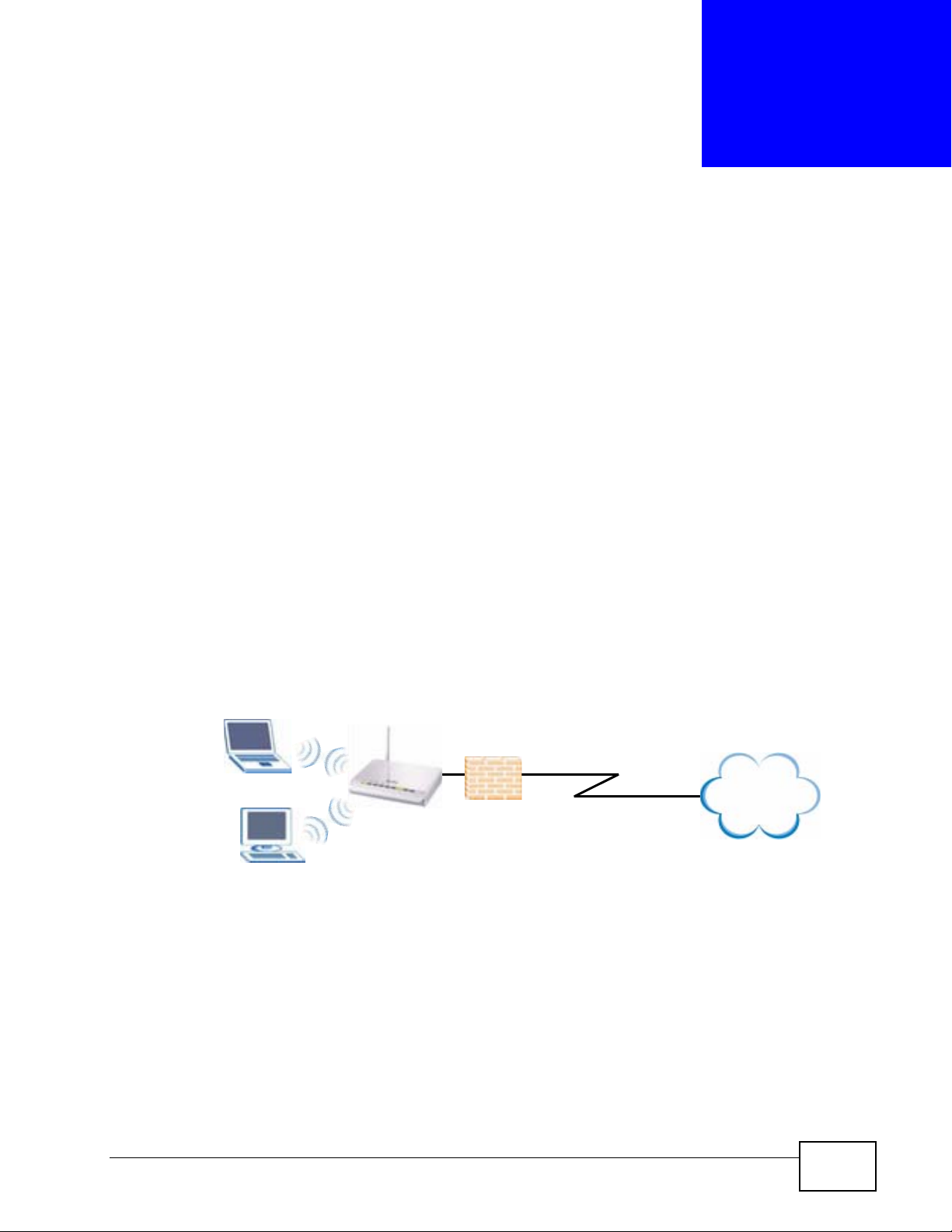
The following figure shows computers in a WLAN connecting to the P-320W v3
(A), which has a DSL connection to the Internet. The P-320W v3 has a built-in
firewall (B) to protect the network. It also has the Network Address Translation
(NAT) feature enabled by default.
Figure 1 Secure Wireless Internet Access in Router Mode
WLAN
A
The P-320W v3 can also serve as a wireless client enabling network devices to
connect to an existing wired or wireless network. Features, such as firewall and
NAT, are available. Networking devices cannot connect wirelessly to the P-320W
v3 when it is acting as a wireless client.
B
DSL
Internet
P-320W v3 User’s Guide
21
Page 22
Chapter 1 Getting to Know Your P-320W v3
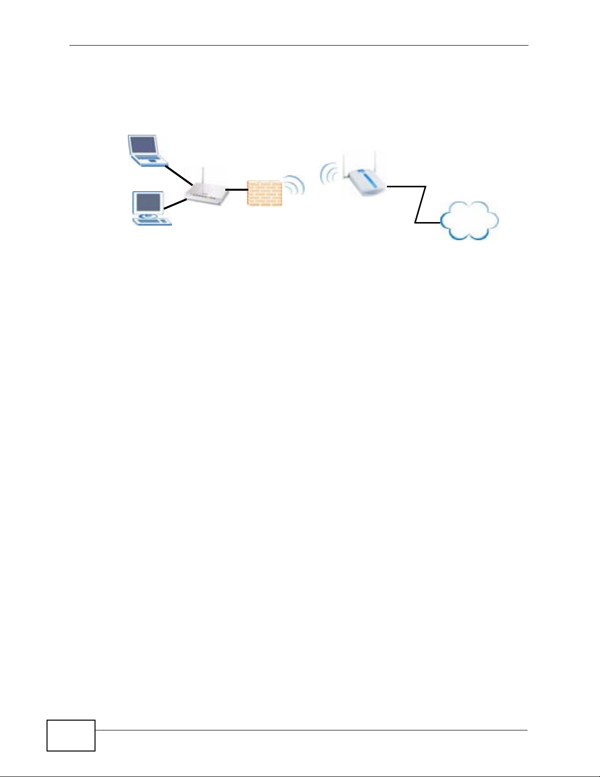
In the following figure, the P-320W v3 (A) enables the wired computers to connect
to the access point (B) and gain access to LAN/Internet.
Figure 2 Using the P-320W v3 as a Wireless Client
Firewall
ISP
DSL
A
B
Internet
1.2 Ways to Manage the P-320W v3
Use any of the following methods to manage the P-320W v3.
• Web Configurator. This is recommended for everyday management of the P-
320W v3 using a (supported) web browser.
• SNMP. Simple Network Management Protocol is a communication protocol for
collecting information from devices on the network.
1.3 Good Habits for Managing the P-320W v3
Do the following things regularly to make the P-320W v3 more secure and to
manage the P-320W v3 more effectively.
22
• Change the password. Use a password that’s not easy to guess and that consists
of different types of characters, such as numbers and letters.
• Write down the password and put it in a safe place.
• Back up the configuration (and make sure you know how to restore it).
Restoring an earlier working configuration may be useful if the device becomes
unstable or even crashes. If you forget your password, you will have to reset the
P-320W v3 to its factory default settings. If you backed up an earlier
configuration file, you would not have to totally re-configure the P-320W v3. You
could simply restore your last configuration.
P-320W v3 User’s Guide
Page 23
1.4 LEDs
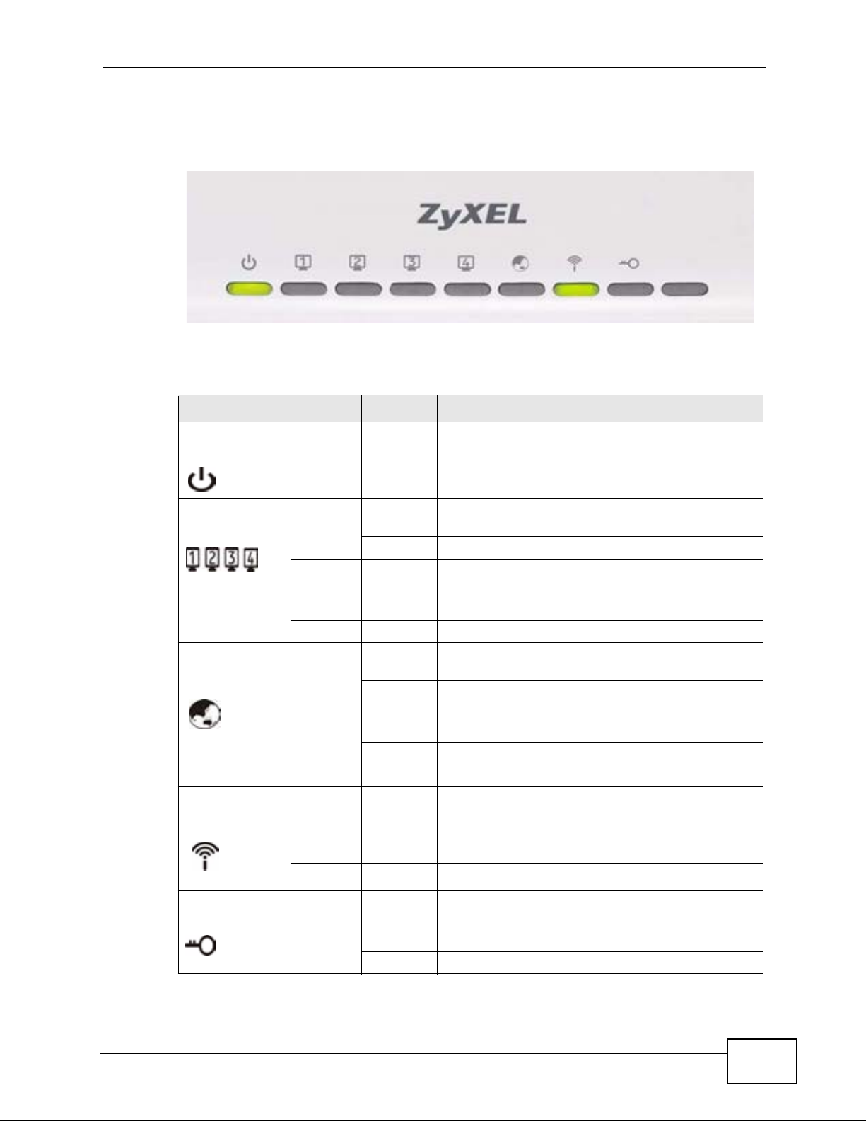
Figure 3 Front Panel
The following table describes the LEDs.
Table 1 Front Panel LEDs
LED COLOR STATUS DESCRIPTION
POWER Green On The P-320W v3 is receiving power and
Chapter 1 Getting to Know Your P-320W v3
functioning properly.
Off The P-320W v3 is not receiving power.
LAN 1-4 Green On The P-320W v3 has a successful 10MB Ethernet
connection.
Blinking The P-320W v3 is sending/receiving data.
Amber On The P-320W v3 has a successful 100MB Ethernet
connection.
Blinking The P-320W v3 is sending/receiving data.
Off The LAN is not connected.
WAN Green On The P-320W v3 has a successful 10MB WAN
connection.
Blinking The P-320W v3 is sending/receiving data.
Amber On The P-320W v3 has a successful 100MB Ethernet
connection.
Blinking The P-320W v3 is sending/receiving data.
Off The WAN connection is not ready, or has failed.
WLAN Green On The P-320W v3 is ready, but is not sending/
receiving data through the wireless LAN.
Blinking The P-320W v3 is sending/receiving data
through the wireless LAN.
Off The wireless LAN is not ready or has failed.
WPS Green On WPS (WiFi Protected Setp) is configurered on
your device.
Blinking The P-320W v3 is negotiating WPS.
Off WPS is disabled on your device.
P-320W v3 User’s Guide
23
Page 24

Chapter 1 Getting to Know Your P-320W v3
24
P-320W v3 User’s Guide
Page 25

CHAPTER 2
Introducing the Web
Configurator
This chapter describes how to access the P-320W v3 web configurator and
provides an overview of its screens.
2.1 Web Configurator Overview
The web configurator is an HTML-based management interface that allows easy
setup and management of the P-320W v3 via Internet browser. Use Internet
Explorer 6.0 and later or Netscape Navigator 7.0 and later versions or Safari 2.0
or later versions. The recommended screen resolution is 1024 by 768 pixels.
In order to use the web configurator you need to allow:
• Web browser pop-up windows from your device. Web pop-up blocking is enabled
by default in Windows XP SP (Service Pack) 2.
• JavaScripts (enabled by default).
• Java permissions (enabled by default).
Refer to the Troubleshooting chapter to see how to make sure these functions are
allowed in Internet Explorer.
2.2 Accessing the Web Configurator
1 Make sure your P-320W v3 hardware is properly connected and prepare your
computer or computer network to connect to the P-320W v3 (refer to the Quick
Start Guide).
2 Launch your web browser.
3 Type "http://192.168.1.1" as the website address.
P-320W v3 User’s Guide
25
Page 26
Chapter 2 Introducing the Web Configurator
Your computer must be in the same subnet in order to access this website
address.
Note: Enable the DHCP Server. The P-320W v3 assigns your computer an IP address
on the same subnet.
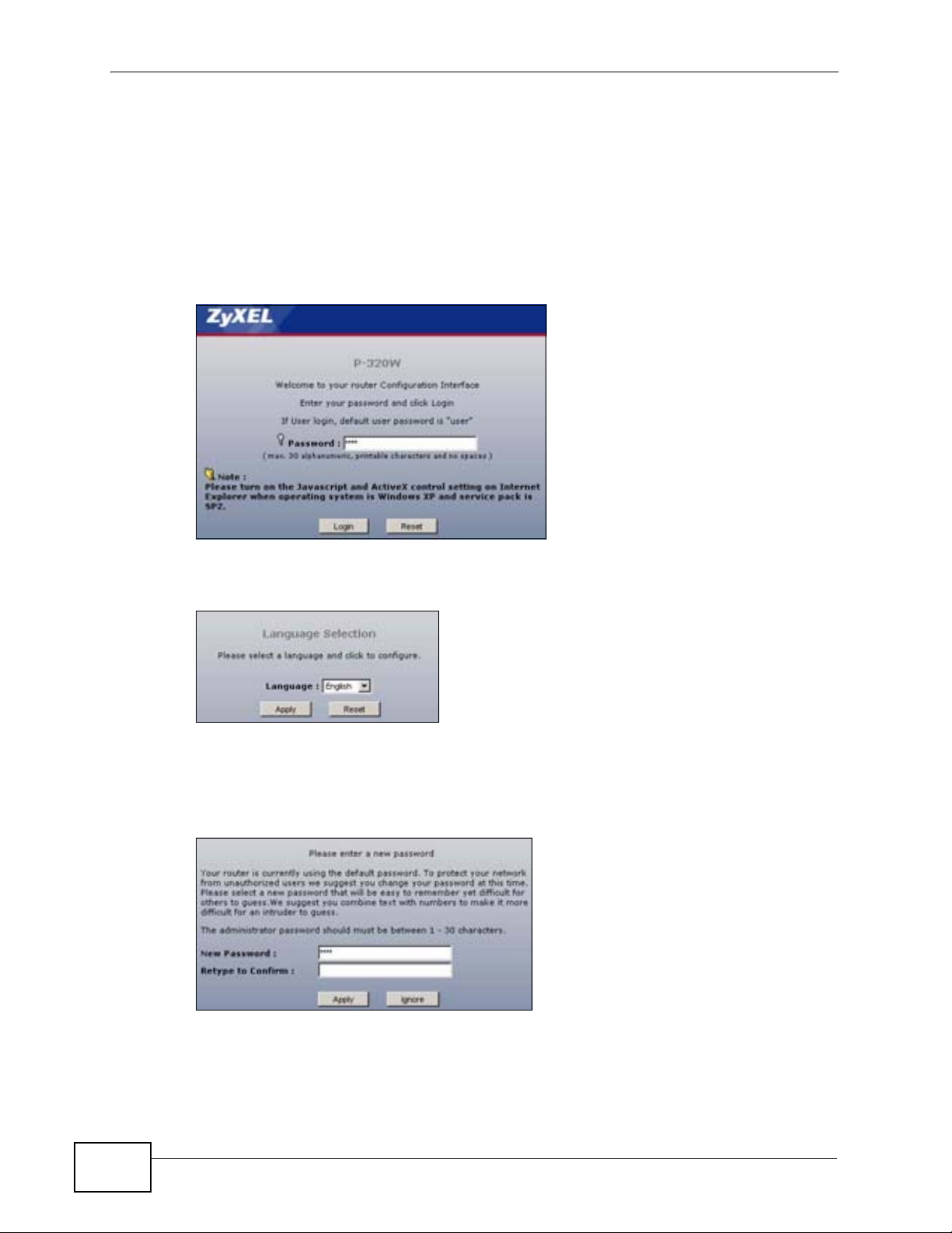
4 Type "1234" (default) as the password and click Login. In some versions, the
default password appears automatically - if this is the case, click Login.
Figure 4 Change Password Screen
5 Select your language in the screen that follows and click Apply or click Reset.
Figure 5 Language Selection
6 You should see a screen asking you to change your password (highly
recommended) as shown next. Type a new password (and retype it to confirm)
and click Apply or click Ignore.
Figure 6 Change Password Screen
26
7 Click Go to Wizard Setup to use the Configuration Wizard for basic Internet and
Wireless setup.
P-320W v3 User’s Guide
Page 27
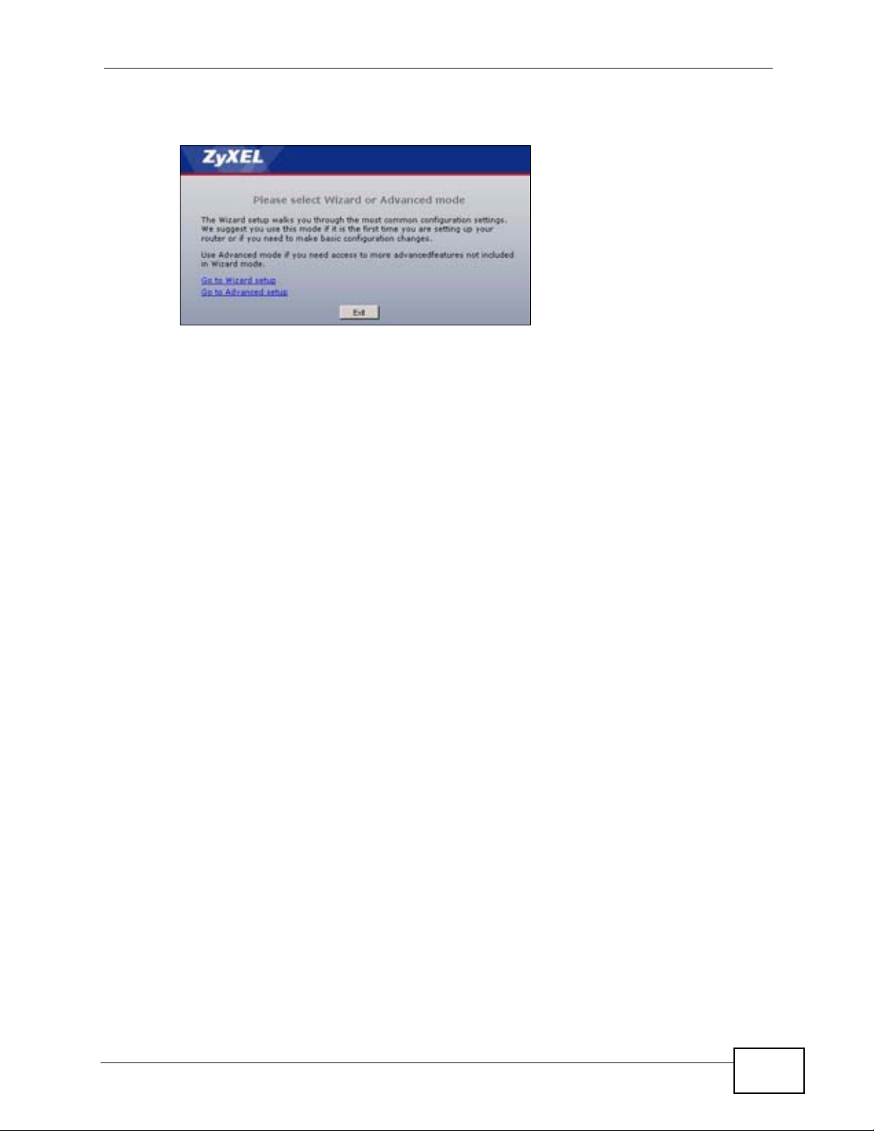
8 Click Go to Advanced Setup to view and configure all the P-320W v3’s settings.
Figure 7 Choose Your Setup Mode.
Note: The management session automatically times out when the time period set in
the Administrator Inactivity Timer field expires (default five minutes). Simply
log back into the P-320W v3 if this happens.
2.3 Resetting the P-320W v3
Chapter 2 Introducing the Web Configurator
If you forget your password or IP address, or you cannot access the web
configurator, you will need to use the RESET button at the back of the P-320W v3
to reload the factory-default configuration file. This means that you will lose all
configurations that you had previously saved, the password will be reset to “1234”
and the IP address will be reset to “192.168.1.1”.
2.3.1 Procedure to Use the Reset Button
1 Make sure the power LED is on.
2 Press the RESET button for longer than 1 second to restart/reboot the P-320W v3.
3 Press the RESET button for longer than five seconds to set the P-320W v3 back to
its factory-default configurations.
2.4 Navigating the Web Configurator
The following summarizes how to navigate the web configurator from the Status
screen.
P-320W v3 User’s Guide
27
Page 28
Chapter 2 Introducing the Web Configurator
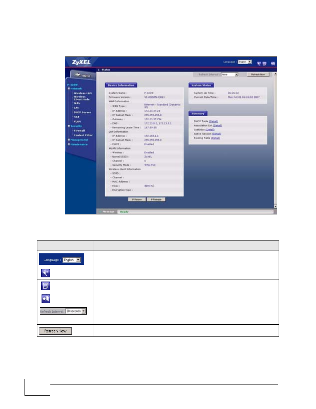
Click on Status. The screen below shows the status screen.
Figure 8 Web Configurator Status Screen
The following table describes the icons shown in the Status screen.
Table 2 Status Screen Icon Key
ICON DESCRIPTION
Select a language from the drop-down list box to have the web configurator
display in that language.
Click this icon to open the setup wizard.
Click this icon to view copyright and a link for related product information.
Click this icon at any time to exit the web configurator.
Select a number of seconds or None from the drop-down list box to refresh
all screen statistics automatically at the end of every time interval or to not
refresh the screen statistics.
Click this button to refresh the status screen statistics.
28
P-320W v3 User’s Guide
Page 29

Chapter 2 Introducing the Web Configurator
The following table describes the labels shown in the Status screen.
Table 3 Web Configurator Status Screen
LABEL DESCRIPTION
Device Information
System Name This is the System Name you enter in the Maintenance > System >
General screen. It is for identification purposes.
Firmware Version This is the firmware version and the date created.
WAN Information
WAN Type This shows the P-320W v3’s WAN type or how it acquires its WAN IP
address.
- IP Address This shows the WAN port’s IP address.
- IP Subnet Mask This shows the WAN port’s subnet mask.
- Gateway This shows the gateway address of the WAN connection.
- DNS This shows the Domain Name System (DNS) addresses of the WAN
connection.
- Remaining Lease
Time
LAN Information
- IP Address This shows the LAN port’s IP address.
- IP Subnet Mask This shows the LAN port’s subnet mask.
- DHCP This shows the LAN port’s DHCP is enabled.
WLAN Information
- Wireless This shows if the wireless LAN is enabled.
- Name(SSID) This shows a descriptive name used to identify the P-320W v3 in the
- Channel This shows the channel number which you select manually.
This shows how long the P-320W v3 can use the current WAN IP address.
wireless LAN.
Note: To comply with US FCC regulation, the country selection
function has been completely removed from all US models. The
above function is for non-US models only.
- Security Mode This shows the level of wireless security the P-320W v3 is using.
Wireless client Information
- SSID This shows a descriptive name used to identify the P-320W v3 in the guest
WLAN network.
- Channel This shows the channel number which you select manually.
Note: To comply with US FCC regulation, the country selection
function has been completely removed from all US models. The
above function is for non-US models only.
- MAC Address This shows the wireless adapter MAC Address of guest WLAN on your
device.
- RSSI This shows the IP address for guest WLAN network.
- Encryption Type This shows the subnet mask for guest WLAN network.
P-320W v3 User’s Guide
29
Page 30

Chapter 2 Introducing the Web Configurator
Table 3 Web Configurator Status Screen (continued)
LABEL DESCRIPTION
System Status
- System Up Time This is the total time the P-320W v3 has been on.
- Current Date/Time This field displays your P-320W v3’s present date and time.
Summary
- DHCP Table Use this screen to view current DHCP client information.
- Association List Use this screen to view the a list of devices the P-320W v3 is currently
associated with.
- Statistics Use this screen to view port status and packet specific statistics.
- Active Session Use this screen to view a list of wireless clients currently connected to the
P-320W v3.
- Routing Table Use this screen to view a list of the traffic routes used by the P-320W v3.
IP Renew Click this to renew the P-320W v3’s IP address.
IP Release Click this to release the P-320W v3’s IP address.
2.4.1 Navigation Panel
Use the sub-menus on the navigation panel to configure P-320W v3 features.
The following table describes the sub-menus.
Table 4 Sub-menus
LINK TAB FUNCTION
Status This screen shows the P-320W v3’s general device, system
and interface status information. Use this screen to access
the wizard, and summary statistics tables.
Network
Wireless
LAN
Wireless
Client Mode
WAN Internet
General Use this screen to configure wireless LAN.
MAC Filter Use the MAC filter screen to configure the P-320W v3 to
block access to devices or block the devices from
accessing the P-320W v3.
WPS Use this screen to configure WPS.
WPS
Station
Advanced This screen allows you to configure advanced wireless
Connection
Advanced Use this screen to configure other advanced properties.
Traffic
Redirect
Use this screen to add stations to the wireless network via
the Push Button.
settings.
This screen allows you to use your P-320W v3 as a
wireless client and connect to a wireless access point.
This screen allows you to configure ISP parameters, WAN
IP address assignment, DNS servers and the WAN MAC
address.
Use this screen to enable a backup gateway IP address for
the P-320W v3.
30
P-320W v3 User’s Guide
Page 31

Chapter 2 Introducing the Web Configurator
Table 4 Sub-menus
LINK TAB FUNCTION
LAN IP Use this screen to configure LAN IP address and subnet
mask.
DHCP
Server
NAT General Use this screen to enable NAT.
VLAN VLAN Setup Use this screen to assign VLAN IDs to the physical ports of
Security
Firewall General Use this screen to activate/deactivate the firewall.
Content
Filter
Management
IP Static
Route
Remote
MGMT
UPnP General Use this screen to enable UPnP on the P-320W v3.
Maintenance
System General Use this screen to view and change administrative settings
Logs View Log Use this screen to view the logs for the categories that you
General Use this screen to enable the P-320W v3’s DHCP server.
Static DHCP Use this screen to assign permanent IP addresses to
specific devices.
Client List Use this screen to view current DHCP client information
and to always assign an IP address to a MAC address (and
host name).
Port
Forwarding
Trigger Port Use this screen to change your P-320W v3’s port
Services This screen shows a summary of the firewall rules, and
Filter Use this screen to block certain web features and sites
IP Static
Route
WWW Use this screen to configure through which interface(s)
SNMP Use this screen to configure SNMP in your P-320W v3.
Security Use this screen to set your P-320W v3 to not respond to
Dynamic
DNS
Time
Setting
Log
Settings
Use this screen to configure servers behind the P-320W
v3.
triggering settings.
the P-320W v3.
allows you to edit/add a firewall rule.
containing certain keywords in the URL.
Use this screen to configure IP static routes.
and from which IP address(es) users can use HTTP to
manage the P-320W v3.
ping from WAN.
such as system and domain names, password and
inactivity timer.
Use this screen to enable dynamic DNS.
Use this screen to change your P-320W v3’s time and
date.
selected.
Use this screen to change your P-320W v3’s log settings.
P-320W v3 User’s Guide
31
Page 32

Chapter 2 Introducing the Web Configurator
Table 4 Sub-menus
LINK TAB FUNCTION
Tools Firmware Use this screen to upload firmware to your P-320W v3.
ConfigurationUse this screen to backup and restore the configuration or
reset the factory defaults to your P-320W v3.
Restart This screen allows you to reboot the P-320W v3 without
turning the power off.
2.4.2 Summary: DHCP Table
DHCP (Dynamic Host Configuration Protocol, RFC 2131 and RFC 2132) allows
individual clients to obtain TCP/IP configuration at start-up from a server. You can
configure the P-320W v3’s LAN and/or Guest WLAN as DHCP server(s) or disable
them. When configured as a server, the P-320W v3 provides the TCP/IP
configuration for the clients. If DHCP service is disabled, you must have another
DHCP server on that network, or else the computer must be manually configured.
Click the DHCP Table (Details...) hyperlink in the Status screen. Read-only
information here relates to your DHCP status. The DHCP table shows current
DHCP client information (including IP Address, Host Name and MAC Address)
of all network clients using the P-320W v3’s DHCP server.
Figure 9 Summary: DHCP Table
The following table describes the labels in this screen.
Table 5 Summary: DHCP Table
LABEL DESCRIPTION
# This is the index number of the client.
IP Address This field displays the IP address relative to the # field listed above.
Host Name This field displays the computer host name.
MAC Address This field shows the MAC address of the computer with the name in the
Host Name field.
Every Ethernet device has a unique MAC (Media Access Control) address
which uniquely identifies a device. The MAC address is assigned at the
factory and consists of six pairs of hexadecimal characters, for example,
00:A0:C5:00:00:02.
Refresh Click Refresh to renew the screen.
32
P-320W v3 User’s Guide
Page 33

2.4.3 Summary: Association List
Click the Association List (Details...) hyperlink in the Status screen. Read-only
information here includes the MAC address of a device and its time of association
with the P-320W v3. Association means that a wireless client (for example, your
network or computer with a wireless network card) has connected successfully to
the AP (or wireless router) using the same SSID, channel and security settings.
Figure 10 Summary: Association List
The following table describes the labels in this screen.
Table 6 Summary: Association List
LABEL DESCRIPTION
# This is the index number of the client.
MAC Address This shows the MAC address of the device associated with the P-320W v3.
Association
Time
Refresh Click Refresh to renew the screen.
This shows the date and time when the association with a device is made.
Chapter 2 Introducing the Web Configurator
2.4.4 Summary: Statistics
Click the Statistics (Details...) hyperlink in the Status screen. Read-only
information here includes port status, packet specific statistics and the "system up
time". The Poll Interval(s) field is configurable and is used for refreshing the
screen.
Figure 11 Summary: Statistics
P-320W v3 User’s Guide
33
Page 34

Chapter 2 Introducing the Web Configurator
The following table describes the labels in this screen.
Table 7 Summary: Statistics
LABEL DESCRIPTION
Port This is the P-320W v3’s port type.
TxPkts This is the number of transmitted packets on this port.
RxPkts This is the number of received packets on this port.
System Up Time This is the total time the P-320W v3 has been on.
Poll Interval(s) Enter the time interval for refreshing statistics in this field.
Set Interval Click this button to apply the new poll interval you entered in the Poll
Interval(s) field.
Stop Click Stop to stop refreshing statistics.
2.4.5 Summary: Active Session
Click the Active Session (Details...) hyperlink in the Status screen. View a list
of devices that are currently associated to the P-320W v3 and read-only
information such as internal/external IP addresses and Time-out.
Figure 12 Summary: Active Session
The following table describes the labels in this screen.
Table 8 Summary: Active Sessiont
LABEL DESCRIPTION
# This is the index number of the active session.
Internal This is the internal IP address of the device.
Protocol This is the transfer protocol used.
External This is the external IP address of the device.
NAT This is the numerical tag for the NAT entry.
Time out This is the time out value (in minutes) of the NAT entry.
34
P-320W v3 User’s Guide
Page 35

Table 8 Summary: Active Sessiont
LABEL DESCRIPTION
Page... (Active
Session Number)
Previous Click this to go to the previous page.
Next Click this to go to the next page.
First Page Click this to go to the first page.
Last Page Click this to go to the last page.
Refresh Click Refresh to renew the screen.
This shows the current page you are looking at as well as the total
number of pages of the association list.
2.4.6 Summary: Routing Table
Click the Routing Table (Details...) hyperlink in the Status screen. View a list of
the static routes configured in the P-320W v3.
Figure 13 Summary: Routing Table
Chapter 2 Introducing the Web Configurator
The following table describes the labels in this screen.
Table 9 Summary: Routing Table
LABEL DESCRIPTION
# This is the index number of the routing entry.
Destination IP
Address
IP Subnet Mask This is teh IP subnet mask of the traffic.
Gateway IP
Address
Metric This is the numerical tag for the routing entry.
Refresh Click Refresh to renew the screen.
This is the destination IP address of the outgoing traffic.
This is the gateway IP address of the host computer.
P-320W v3 User’s Guide
35
Page 36

Chapter 2 Introducing the Web Configurator
36
P-320W v3 User’s Guide
Page 37

CHAPTER 3
Connection Wizard
This chapter provides information on the wizard setup screens in the web
configurator.
3.1 Wizard Setup
The web configurator’s wizard setup helps you configure your device to access the
Internet. Refer to your ISP (Internet Service Provider) checklist in the Quick Start
Guide to know what to enter in each field. Leave a field blank if you don’t have
that information.
1 After you access the P-320W v3 web configurator, click the Go to Wizard setup
hyperlink.
You can click the Go to Advanced setup hyperlink to skip this wizard setup and
configure advanced features accordingly.
Figure 14 Select Wizard or Advanced Mode
P-320W v3 User’s Guide
37
Page 38

Chapter 3 Connection Wizard
2 Read the on-screen information and click Next.
Figure 15 Welcome to the Connection Wizard
3.2 Connection Wizard: STEP 1: System
Information
System Information contains administrative and system-related information.
3.2.1 System Name
System Name is for identification purposes. However, because some ISPs check
this name you should enter your computer's "Computer Name".
• In Windows 95/98 click Start, Settings, Control Panel, Network. Click the
Identification tab, note the entry for the Computer Name field and enter it as
the System Name.
• In Windows 2000, click Start, Settings and Control Panel and then doubleclick System. Click the Network Identification tab and then the Properties
button. Note the entry for the Computer name field and enter it as the
System Name.
• In Windows XP, click Start, My Computer, View system information and
then click the Computer Name tab. Note the entry in the Full computer
name field and enter it as the P-320W v3 System Name.
3.2.2 Domain Name
The Domain Name entry is what is propagated to the DHCP clients on the LAN. If
you leave this blank, the domain name obtained by DHCP from the ISP is used.
While you must enter the host name (System Name) on each individual computer,
the domain name can be assigned from the P-320W v3 via DHCP.
38
P-320W v3 User’s Guide
Page 39

Chapter 3 Connection Wizard
Click Next to configure the P-320W v3 for Internet access.
Figure 16 Wizard Step 1: System Information
The following table describes the labels in this screen.
Table 10 Wizard Step 1: System Information
LABEL DESCRIPTION
System
Name
Domain
Name
Back Click Back to display the previous screen.
Next Click Next to proceed to the next screen.
Exit Click Exit to close the wizard screen without saving.
System Name is a unique name to identify the P-320W v3 in an Ethernet
network. Enter a descriptive name. This name can be up to 30
alphanumeric characters long. Spaces are not allowed, but dashes "-" and
underscores "_" are accepted.
Type the domain name (if you know it) here. If you leave this field blank,
the ISP may assign a domain name via DHCP. The domain name entered
by you is given priority over the ISP assigned domain name.
P-320W v3 User’s Guide
39
Page 40

Chapter 3 Connection Wizard
3.3 Connection Wizard: STEP 2: Wireless LAN
Set up your wireless LAN using the following screen.
Figure 17 Wizard Step 2: Wireless LAN
The following table describes the labels in this screen.
Table 11 Wizard Step 2: Wireless LAN
LABEL DESCRIPTION
Name
(SSID)
Channel
Selection
Enter a descriptive name (up to 32 printable 7-bit ASCII characters) for the
wireless LAN.
If you change this field on the P-320W v3, make sure all wireless stations
use the same SSID in order to access the network.
The range of radio frequencies used by IEEE 802.11b/g wireless devices is
called a channel.
Select a channel that is not used by any nearby devices.
Note: To comply with US FCC regulation, the country selection
function has been completely removed from all US models. The
above function is for non-US models only.
40
P-320W v3 User’s Guide
Page 41

Chapter 3 Connection Wizard
Table 11 Wizard Step 2: Wireless LAN
LABEL DESCRIPTION
Security Select a Security level from the drop-down list box.
Choose Auto (WPA-PSK with self-generated key) to have the P-320W
v3 generate a pre-shared key automatically. A screen pops up displaying
the generated pre-shared key after you click Next. Write down the key for
use later when connecting other wireless devices to your network. Click OK
to continue.
Choose None to have no wireless LAN security configured. If you do not
enable any wireless security on your P-320W v3, your network is accessible
to any wireless networking device that is within range. If you choose this
option, skip directly to Section 3.4 on page 43.
Choose Basic (WEP) security if you want to configure WEP Encryption
parameters. If you choose this option, go directly to Section 3.3.1 on page
42. Basic (WEP) is only available when WPS (WiFi Protected Setup) is
disabled. See Section 4.3.5 on page 60 for more information about WPS.
Choose Extend (WPA-PSK with customized key) security to configure a
Pre-Shared Key. Choose this option only if your wireless clients support
WPA-PSK. If you choose this option, skip directly to Section 3.3.2 on page
43.
Back Click Back to display the previous screen.
Next Click Next to proceed to the next screen.
Exit Click Exit to close the wizard screen without saving.
Note: The wireless stations and P-320W v3 must use the same SSID, channel ID and
WEP encryption key (if WEP is enabled), WPA-PSK (if WPA-PSK is enabled) or
WPA2-PSK (if WPA2-PSK is enabled) for wireless communication.
P-320W v3 User’s Guide
41
Page 42

Chapter 3 Connection Wizard
3.3.1 Basic(WEP) Security
Choose Basic(WEP) to setup WEP Encryption parameters.
Figure 18 Wizard Step 2: Basic (WEP) Security
The following table describes the labels in this screen.
Table 12 Wizard Step 2: Basic (WEP) Security
LABEL DESCRIPTION
Passphrase Type a Passphrase (up to 32 printable characters) and click Generate. The
P-320W v3 automatically generates a WEP key.
Click Clear to make this field blank.
WEP
Encryption
ASCII Select this option in order to enter ASCII characters as the WEP keys.
HEX Select this option to enter hexadecimal characters as the WEP keys.
Key 1 to Key 4The WEP keys are used to encrypt data. Both the P-320W v3 and the
Back Click Back to display the previous screen.
Next Click Next to proceed to the next screen.
Exit Click Exit to close the wizard screen without saving.
Select 64-bit WEP or 128-bit WEP to allow data encryption.
The preceding “0x” is entered automatically.
wireless stations must use the same WEP key for data transmission.
If you chose 64-bit WEP, then enter any 5 ASCII characters or 10
hexadecimal characters ("0-9", "A-F").
If you chose 128-bit WEP, then enter 13 ASCII characters or 26
hexadecimal characters ("0-9", "A-F").
You must configure at least one key, only one key can be activated at any
one time. The default key is key 1.
42
P-320W v3 User’s Guide
Page 43

3.3.2 Extend (WPA-PSK) Security
Choose Extend (WPA-PSK) security in the Wireless LAN setup screen to set up a
Pre-Shared Key.
Figure 19 Wizard Step 2: Extend (WPA-PSK) Security
The following table describes the labels in this screen.
Table 13 Wizard Step 2: Extend (WPA-PSK) Security
LABEL DESCRIPTION
Pre-Shared
Key
Back Click Back to display the previous screen.
Next Click Next to proceed to the next screen.
Exit Click Exit to close the wizard screen without saving.
Type from 8 to 63 case-sensitive ASCII characters. You can set up the most
secure wireless connection by configuring WPA in the wireless LAN screens.
You need to configure an authentication server to do this.
Chapter 3 Connection Wizard
3.4 Connection Wizard: STEP 3: Internet
Configuration
The P-320W v3 offers three Internet connection types. They are Ethernet, PPP
over Ethernet or PPTP. The wizard attempts to detect which WAN connection
type you are using. If the wizard does not detect a connection type, you must
select one from the drop-down list box. Check with your ISP to make sure you use
the correct type.
P-320W v3 User’s Guide
43
Page 44

Chapter 3 Connection Wizard
This wizard screen varies according to the connection type that you select.
Figure 20 Wizard Step 3: ISP Parameters.
The following table describes the labels in this screen,
Table 14 Wizard Step 3: ISP Parameters
CONNECTION
TYPE
Ethernet Select the Ethernet option when the WAN port is used as a regular
PPPoE Select the PPP over Ethernet option for a dial-up connection. If
PPTP Select the PPTP option for a dial-up connection.
DESCRIPTION
Ethernet.
your ISP gave you an IP address and/or subnet mask, then select
PPTP.
3.4.1 Ethernet Connection
Choose Ethernet when the WAN port is used as a regular Ethernet.
Figure 21 Wizard Step 3: Ethernet Connection
3.4.2 PPPoE Connection
Point-to-Point Protocol over Ethernet (PPPoE) functions as a dial-up connection.
PPPoE is an IETF (Internet Engineering Task Force) standard specifying how a host
44
P-320W v3 User’s Guide
Page 45

Chapter 3 Connection Wizard
personal computer interacts with a broadband modem (for example DSL, cable,
wireless, etc.) to achieve access to high-speed data networks.
For the service provider, PPPoE offers an access and authentication method that
works with existing access control systems (for instance, RADIUS).
One of the benefits of PPPoE is the ability to let end users access one of multiple
network services, a function known as dynamic service selection. This enables the
service provider to easily create and offer new IP services for specific users.
Operationally, PPPoE saves significant effort for both the subscriber and the ISP/
carrier, as it requires no specific configuration of the broadband modem at the
subscriber’s site.
By implementing PPPoE directly on the P-320W v3 (rather than individual
computers), the computers on the LAN do not need PPPoE software installed,
since the P-320W v3 does that part of the task. Furthermore, with NAT, all of the
LAN's computers will have Internet access.
Refer to the appendix for more information on PPPoE.
Figure 22 Wizard Step 3: PPPoE Connection
The following table describes the labels in this screen.
Table 15 Wizard Step 3: PPPoE Connection
LABEL DESCRIPTION
ISP Parameter for Internet Access
Connection
Type
Service Name Type the name of your service provider.
User Name Type the user name given to you by your ISP.
Password Type the password associated with the user name above.
Back Click Back to return to the previous screen.
Select the PPP over Ethernet option for a dial-up connection.
P-320W v3 User’s Guide
45
Page 46

Chapter 3 Connection Wizard
Table 15 Wizard Step 3: PPPoE Connection
LABEL DESCRIPTION
Next Click Next to continue.
Exit Click Exit to close the wizard screen without saving.
3.4.3 PPTP Connection
Point-to-Point Tunneling Protocol (PPTP) is a network protocol that enables
transfers of data from a remote client to a private server, creating a Virtual Private
Network (VPN) using TCP/IP-based networks.
PPTP supports on-demand, multi-protocol, and virtual private networking over
public networks, such as the Internet.
Refer to the appendix for more information on PPTP.
Note: The P-320W v3 supports one PPTP server connection at any given time.
Figure 23 Wizard Step 3: PPTP Connection
46
P-320W v3 User’s Guide
Page 47

Chapter 3 Connection Wizard
The following table describes the fields in this screen
Table 16 Wizard Step 3: PPTP Connection
LABEL DESCRIPTION
ISP Parameters for Internet Access
Connection Type Select PPTP from the drop-down list box. To configure a PPTP client,
you must configure the User Name and Password fields for a PPP
connection and the PPTP parameters for a PPTP connection.
User Name Type the user name given to you by your ISP.
Password Type the password associated with the User Name above.
PPTP Configuration
Get
automatically
from ISP
Use fixed IP
address
My IP
Address
My IP Subnet
Mask
Server IP
Address
Connection ID/
Name
Select this radio button if your ISP did not assign you a fixed IP
address.
Select this radio button, provided by your ISP to give the P-320W v3 a
fixed, unique IP address.
Type the (static) IP address assigned to you by your ISP.
Type the subnet mask assigned to you by your ISP (if given).
Type the IP address of the PPTP server.
Enter the connection ID or connection name in this field. It must follow
the "c:id" and "n:name" format. For example, C:12 or N:My ISP.
This field is optional and depends on the requirements of your ISP.
Back Click Back to return to the previous screen.
Next Click Next to continue.
Exit Click Exit to close the wizard screen without saving.
3.4.4 Your IP Address
The following wizard screen allows you to assign a fixed IP address or give the P320W v3 an automatically assigned IP address depending on your ISP.
Figure 24 Wizard Step 3: Your IP Address
P-320W v3 User’s Guide
47
Page 48

Chapter 3 Connection Wizard
The following table describes the labels in this screen
Table 17 Wizard Step 3: Your IP Address
LABEL DESCRIPTION
Get automatically from
your ISP
Use fixed IP address
provided by your ISP
Back Click Back to return to the previous screen.
Next Click Next to continue.
Exit Click Exit to close the wizard screen without saving.
Select this option If your ISP did not assign you a fixed IP
address. This is the default selection. If you choose this option,
skip directly to section Section 3.4.9 on page 51.
Select this option if you were given IP address and/or DNS server
settings by the ISP. The fixed IP address should be in the same
subnet as your broadband modem or router.
3.4.5 WAN IP Address Assignment
Every computer on the Internet must have a unique IP address. If your networks
are isolated from the Internet, for instance, only between your two branch offices,
you can assign any IP addresses to the hosts without problems. However, the
Internet Assigned Numbers Authority (IANA) has reserved the following three
blocks of IP addresses specifically for private networks.
Table 18 Private IP Address Ranges
10.0.0.0 - 10.255.255.255
172.16.0.0 - 172.31.255.255
192.168.0.0 - 192.168.255.255
You can obtain your IP address from the IANA, from an ISP or have it assigned by
a private network. If you belong to a small organization and your Internet access
is through an ISP, the ISP can provide you with the Internet addresses for your
local networks. On the other hand, if you are part of a much larger organization,
you should consult your network administrator for the appropriate IP addresses.
Note: Regardless of your particular situation, do not create an arbitrary IP address;
always follow the guidelines above. For more information on address
assignment, please refer to RFC 1597, Address Allocation for Private Internets
and RFC 1466, Guidelines for Management of IP Address Space.
3.4.6 IP Address and Subnet Mask
Similar to the way houses on a street share a common street name, so too do
computers on a LAN share one common network number.
48
Where you obtain your network number depends on your particular situation. If
the ISP or your network administrator assigns you a block of registered IP
P-320W v3 User’s Guide
Page 49

Chapter 3 Connection Wizard
addresses, follow their instructions in selecting the IP addresses and the subnet
mask.
If the ISP did not explicitly give you an IP network number, then most likely you
have a single user account and the ISP will assign you a dynamic IP address when
the connection is established. The Internet Assigned Number Authority (IANA)
reserved this block of addresses specifically for private use; please do not use any
other number unless you are told otherwise. Let's say you select 192.168.1.0 as
the network number; which covers 254 individual addresses, from 192.168.1.1 to
192.168.1.254 (zero and 255 are reserved). In other words, the first three
numbers specify the network number while the last number identifies an individual
computer on that network.
Once you have decided on the network number, pick an IP address that is easy to
remember, for instance, 192.168.1.1, for your P-320W v3, but make sure that no
other device on your network is using that IP address.
The subnet mask specifies the network number portion of an IP address. Your P320W v3 will compute the subnet mask automatically based on the IP address
that you entered. You don't need to change the subnet mask computed by the P320W v3 unless you are instructed to do otherwise.
3.4.7 DNS Server Address Assignment
Use DNS (Domain Name System) to map a domain name to its corresponding IP
address and vice versa, for instance, the IP address of www.zyxel.com is
204.217.0.2. The DNS server is extremely important because without it, you must
know the IP address of a computer before you can access it.
The P-320W v3 can get the DNS server addresses in the following ways.
1 The ISP tells you the DNS server addresses, usually in the form of an information
sheet, when you sign up. If your ISP gives you DNS server addresses, enter them
in the DNS Server fields in the Wizard and/or WAN > Internet Connection
screen.
2 If the ISP did not give you DNS server information, leave the DNS Server fields
set to 0.0.0.0 in the Wizard screen and/or set to From ISP in the WAN >
Internet Connection screen for the ISP to dynamically assign the DNS server IP
addresses.
P-320W v3 User’s Guide
49
Page 50

Chapter 3 Connection Wizard
3.4.8 WAN IP and DNS Server Address Assignment
The following wizard screen allows you to assign a fixed WAN IP address and DNS
server addresses.
Figure 25 Wizard Step 3: WAN IP and DNS Server Addresses
The following table describes the labels in this screen
Table 19 Wizard Step 3: WAN IP and DNS Server Addresses
LABEL DESCRIPTION
WAN IP Address Assignment
My WAN IP Address Enter your WAN IP address in this field. The WAN IP address
should be in the same subnet as your DSL/Cable modem or
router.
My WAN IP Subnet
Mask
Gateway IP Address Enter the gateway IP address in this field.
System DNS Server Address Assignment (if applicable)
DNS (Domain Name System) is for mapping a domain name to its corresponding IP
address and vice versa. The DNS server is extremely important because without it, you
must know the IP address of a computer before you can access it. The P-320W v3 uses a
system DNS server (in the order you specify here) to resolve domain names for DDNS and
the time server.
First DNS Server
Second DNS Server
Third DNS Server
Back Click Back to return to the previous screen.
Next Click Next to continue.
Exit Click Exit to close the wizard screen without saving.
Enter the IP subnet mask in this field.
Enter the DNS server's IP address in the fields provided.
If you do not configure a system DNS server, you must use IP
addresses when configuring DDNS and the time server.
50
P-320W v3 User’s Guide
Page 51

3.4.9 WAN MAC Address
Every Ethernet device has a unique MAC (Media Access Control) address. The MAC
address is assigned at the factory and consists of six pairs of hexadecimal
characters, for example, 00:A0:C5:00:00:02.
Table 20 Example of Network Properties for LAN Servers with Fixed IP Addresses
Choose an IP address 192.168.1.2-192.168.1.32; 192.168.1.65-192.168.1.254.
Subnet mask 255.255.255.0
Gateway (or default route) 192.168.1.1(P-320W v3 LAN IP)
This screen allows users to configure the WAN port's MAC address by either using
the P-320W v3’s MAC address, copying the MAC address from a computer on your
LAN or manually entering a MAC address. Once it is successfully configured, the
address will be copied to the "rom" file (ZyNOS configuration file). It will not
change unless you change the setting or upload a different "rom" file. It is
advisable to clone the MAC address from a computer on your LAN even if your ISP
does not presently require MAC address authentication.
Chapter 3 Connection Wizard
Figure 26 Wizard Step 3: WAN MAC Address
The following table describes the fields in this screen.
Table 21 Wizard Step 3: WAN MAC Address
LABEL DESCRIPTION
Factory Default Select Factory Default to use the factory assigned default MAC
address.
Spoof the
computer’s MAC
address
Back Click Back to return to the previous screen.
Next Click Next to continue.
Exit Click Exit to close the wizard screen without saving.
Select this option, enter the IP address of the computer on the LAN
whose MAC you are cloning and click Clone MAC.
It is advisable to clone the MAC address from a computer on your LAN
even if your ISP does not presently require MAC address
authentication.
P-320W v3 User’s Guide
51
Page 52

Chapter 3 Connection Wizard
3.5 Connection Wizard Complete
Click Apply to save your configuration.
Figure 27 Connection Wizard Save
Follow the on-screen instructions and click Finish to complete the wizard setup.
Figure 28 Connection Wizard Complete
Well done! You have successfully set up your P-320W v3 to operate on your
network and access the Internet.
52
P-320W v3 User’s Guide
Page 53

Wireless LAN (55)
Wireless Tutorial (77)
WAN (107)
LAN (85)
Guest WLAN (117)
DHCP Server (89)
PART II
Network
Network Address Translation (NAT) (93)
Dynamic DNS (123)
53
Page 54

54
Page 55

CHAPTER 4
Wireless LAN
4.1 Overview
This chapter discusses how to configure the wireless network settings in your P320W v3. See the appendices for more detailed information about wireless
networks.
The following figure provides an example of a wireless network.
Figure 29 Example of a Wireless Network
The wireless network is the part in the blue circle. In this wireless network,
devices A and B are called wireless clients. The wireless clients use the access
point (AP) to interact with other devices (such as the printer) or with the Internet.
Your P-320W v3 is the AP.
Every wireless network must follow these basic guidelines.
• Every wireless client in the same wireless network must use the same SSID.
The SSID is the name of the wireless network. It stands for Service Set IDentity.
P-320W v3 User’s Guide
55
Page 56

Chapter 4 Wireless LAN
• If two wireless networks overlap, they should use different channels.
Like radio stations or television channels, each wireless network uses a specific
channel, or frequency, to send and receive information.
• Every wireless client in the same wireless network must use security compatible
with the AP.
Security stops unauthorized devices from using the wireless network. It can also
protect the information that is sent in the wireless network.
4.2 What You Can Do
•Use the General Wireless screen (Section 4.4 on page 60) configure your P-
320W v3 as a wireless router or access point (AP).
•Use the MAC Filter screen (Section 4.5 on page 68) to configure the P-320W v3
to give or deny access to up to 32 devices.
•Use the WPS screen (Section 4.6 on page 69) to enable/disable WPS, view or
generate a new PIN number and check current WPS status.
•Use the WPS Station screen (Section 4.7 on page 70) to add a wireless station
using WPS.
•Use the Wireless LAN Advanced screen (Section 4.8 on page 70) to configure
your P-320W v3’s advanced wireless setup.
4.3 What You Need To Know
The following sections provide information that can help you set up your wireless
network. It also introduces different types of wireless security you can set up in
the wireless network.
4.3.1 SSID
Normally, the AP acts like a beacon and regularly broadcasts the SSID in the area.
You can hide the SSID instead, in which case the AP does not broadcast the SSID.
In addition, you should change the default SSID to something that is difficult to
guess.
This type of security is fairly weak, however, because there are ways for
unauthorized devices to get the SSID. In addition, unauthorized devices can still
see the information that is sent in the wireless network.
56
P-320W v3 User’s Guide
Page 57

4.3.2 MAC Address Filter
Chapter 4 Wireless LAN
Every wireless client has a unique identification number, called a MAC address.1 A
MAC address is usually written using twelve hexadecimal characters
example, 00A0C5000002 or 00:A0:C5:00:00:02. To get the MAC address for each
wireless client, see the appropriate User’s Guide or other documentation.
You can use the MAC address filter to tell the AP which wireless clients are allowed
or not allowed to use the wireless network. If a wireless client is allowed to use the
wireless network, it still has to have the correct settings (SSID, channel, and
security). If a wireless client is not allowed to use the wireless network, it does not
matter if it has the correct settings.
This type of security does not protect the information that is sent in the wireless
network. Furthermore, there are ways for unauthorized devices to get the MAC
address of an authorized wireless client. Then, they can use that MAC address to
use the wireless network.
4.3.3 User Authentication
You can make every user log in to the wireless network before they can use it.
This is called user authentication. However, every wireless client in the wireless
network has to support IEEE 802.1x to do this.
2
; for
For wireless networks, there are two typical places to store the user names and
passwords for each user.
• In the AP: this feature is called a local user database or a local database.
• In a RADIUS server: this is a server used in businesses more than in homes.
If your AP does not provide a local user database and if you do not have a RADIUS
server, you cannot set up user names and passwords for your users.
Unauthorized devices can still see the information that is sent in the wireless
network, even if they cannot use the wireless network. Furthermore, there are
ways for unauthorized wireless users to get a valid user name and password.
Then, they can use that user name and password to use the wireless network.
Local user databases also have an additional limitation that is explained in the
next section.
1. Some wireless devices, such as scanners, can detect wireless networks but cannot use wireless networks.
These kinds of wireless devices might not have MAC addresses.
2. Hexadecimal characters are 0, 1, 2, 3, 4, 5, 6, 7, 8, 9, A, B, C, D, E, and F.
P-320W v3 User’s Guide
57
Page 58

Chapter 4 Wireless LAN
4.3.4 Encryption
Wireless networks can use encryption to protect the information that is sent in the
wireless network. Encryption is like a secret code. If you do not know the secret
code, you cannot understand the message.
The types of encryption you can choose depend on the type of user
authentication. (See Section 4.3.3 on page 57 for information about this.)
Table 22 Types of Encryption for Each Type of Authentication
Weakest No Security WPA
Strongest WPA2-PSK WPA2
For example, if the wireless network has a RADIUS server, you can choose WPA
or WPA2. If users do not log in to the wireless network, you can choose no
encryption, Static WEP, WPA-PSK, or WPA2-PSK.
NO AUTHENTICATION RADIUS SERVER
Static WEP
WPA-PSK
Usually, you should set up the strongest encryption that every wireless client in
the wireless network supports. For example, suppose the AP does not have a local
user database, and you do not have a RADIUS server. Therefore, there is no user
authentication. Suppose the wireless network has two wireless clients. Device A
only supports WEP, and device B supports WEP and WPA. Therefore, you should
set up Static WEP in the wireless network.
Note: It is recommended that wireless networks use WPA-PSK, WPA, or stronger
encryption. IEEE 802.1x and WEP encryption are better than none at all, but it
is still possible for unauthorized devices to figure out the original information
pretty quickly.
Note: It is not possible to use WPA-PSK, WPA or stronger encryption with a local user
database. In this case, it is better to set up stronger encryption with no
authentication than to set up weaker encryption with the local user database.
When you select WPA2 or WPA2-PSK in your P-320W v3, you can also select an
option (WPA Compatible) to support WPA as well. In this case, if some wireless
clients support WPA and some support WPA2, you should set up WPA2-PSK or
WPA2 (depending on the type of wireless network login) and select the WPA
Compatible option in the P-320W v3.
58
Many types of encryption use a key to protect the information in the wireless
network. The longer the key, the stronger the encryption. Every wireless client in
the wireless network must have the same key.
P-320W v3 User’s Guide
Page 59

4.3.4.1 WPA-PSK Application Example
A WPA-PSK application looks as follows.
1 First enter identical passwords into the AP and all wireless clients. The Pre-Shared
Key (PSK) must consist of between 8 and 63 ASCII characters or 64 hexadecimal
characters (including spaces and symbols).
2 The AP checks each wireless client's password and allows it to join the network
only if the password matches.
3 The AP and wireless clients generate a common PMK (Pairwise Master Key). The
key itself is not sent over the network, but is derived from the PSK and the SSID.
4 The AP and wireless clients use the TKIP or AES encryption process, the PMK and
information exchanged in a handshake to create temporal encryption keys. They
use these keys to encrypt data exchanged between them.
Figure 30 WPA-PSK Authentication
Chapter 4 Wireless LAN
4.3.4.2 WPA with RADIUS Application Example
To set up WPA, you need the IP address of the RADIUS server, its port number
(default is 1812), and the RADIUS shared secret. A WPA application example with
an external RADIUS server looks as follows. "A" is the RADIUS server. "DS" is the
distribution system.
1 The AP passes the wireless client's authentication request to the RADIUS server.
2 The RADIUS server then checks the user's identification against its database and
grants or denies network access accordingly.
3 A 256-bit Pairwise Master Key (PMK) is derived from the authentication process by
the RADIUS server and the client.
P-320W v3 User’s Guide
59
Page 60

Chapter 4 Wireless LAN
4 The RADIUS server distributes the PMK to the AP. The AP then sets up a key
hierarchy and management system, using the PMK to dynamically generate
unique data encryption keys. The keys are used to encrypt every data packet that
is wirelessly communicated between the AP and the wireless clients.
Figure 31 WPA with RADIUS Application Example
4.3.5 WiFi Protected Setup
WiFi Protected Setup (WPS) is an industry standard specification, defined by the
WiFi Alliance. WPS allows you to quickly set up a wireless network with strong
security, without having to configure security settings manually. Depending on the
devices in your network, you can either press a button (on the device itself, or in
its configuration utility) or enter a PIN (Personal Identification Number) in the
devices. Then, they connect and set up a secure network by themselves. See how
to set up a secure wireless network using WPS in the Section 6.2 on page 77.
4.4 General Wireless LAN Screen
Use this screen to configure your P-320W v3 as a wireless router or access point
(AP).
The P-320W v3 can broadcast up to four wireless profiles at the same time. This
means that users can connect to the P-320W v3 using different SSIDs.
You can only secure the connection on one SSID profile (AP1). Clients connecting
to the P-320W v3 using different SSIDs are in the same subnet but cannot
communicate with each other.
60
P-320W v3 User’s Guide
Page 61

Chapter 4 Wireless LAN
Note: If you are configuring the P-320W v3 from a computer connected to the wireless
LAN and you change the P-320W v3’s SSID, channel or security settings, you
will lose your wireless connection when you press Apply to confirm. You must
then change the wireless settings of your computer to match the P-320W v3’s
new settings.
Click Network > Wireless LAN to open the General screen.
Figure 32 Network > Wireless LAN > General
The following table describes the general wireless LAN labels in this screen.
Table 23 Network > Wireless LAN > General
LABEL DESCRIPTION
Wireless Setup
Switch AP Select the AP profile you want to configure.
You can enable up to 4 AP profiles with your P-320W v3.
Enable
Wireless LAN
Name(SSID) (Service Set IDentity) The SSID identifies the Service Set with which a
Hide SSID Select this check box to hide the SSID in the outgoing beacon frame so a
Channel
Selection
Click the check box to activate wireless LAN.
wireless station is associated. Wireless stations associating to the access
point (AP) must have the same SSID. Enter a descriptive name (up to 32
printable 7-bit ASCII characters) for the wireless LAN.
station cannot obtain the SSID through scanning using a site survey tool.
Set the operating frequency/channel depending on your particular region.
Select a channel from the drop-down list box. The options vary depending
on whether you are using B/G frequency band and the country you are in.
Refer to the Connection Wizard chapter for more information on channels.
Note: To comply with US FCC regulation, the country selection
function has been completely removed from all US models.
The above function is for non-US models only.
Security
P-320W v3 User’s Guide
61
Page 62
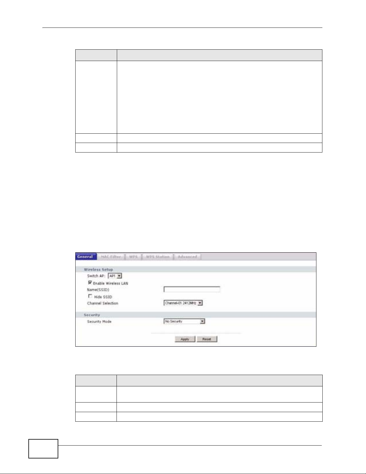
Chapter 4 Wireless LAN
Table 23 Network > Wireless LAN > General
LABEL DESCRIPTION
Security
Mode
Apply Click Apply to save your changes back to the P-320W v3.
Reset Click Reset to reload the previous configuration for this screen.
See the rest of this chapter for information on the other labels in this screen.
4.4.1 No Security
Select Static-WEP, WPA-PSK, WPA, 802.1x + Dynamic WEP or
WPA-PSK/WPA2-PSK (Mixed) to add security on this wireless
network. The wireless clients which want to associate to this network
must have same wireless security settings as this device. After you select
to use a security, additional options appears in this screen. See 4.4.2,
4.4.3, 4.4.4 sections. Or you can select No Security to allow any client to
associate this network without authentication.
Note: If you enable the WPS function, only No Security and WPA-
PSK are available in this option.
Select No Security to allow wireless stations to communicate with the access
points without any data encryption.
Note: If you do not enable any wireless security on your P-320W v3, your network is
accessible to any wireless networking device that is within range.
Figure 33 Network > Wireless LAN > General: No Security
The following table describes the labels in this screen.
Table 24 Wireless No Security
LABEL DESCRIPTION
Security
Mode
Apply Click Apply to save your changes back to the P-320W v3.
Reset Click Reset to reload the previous configuration for this screen.
Choose No Security from the drop-down list box.
62
P-320W v3 User’s Guide
Page 63

4.4.2 WEP Encryption
WEP encryption scrambles the data transmitted between the wireless stations and
the access points to keep network communications private. It encrypts unicast
and multicast communications in a network. Both the wireless stations and the
access points must use the same WEP key.
Your P-320W v3 allows you to configure up to four 64-bit or 128-bit WEP keys but
only one key can be enabled at any one time.
In order to configure and enable WEP encryption; click Network > Wireless LAN
to display the General screen. Select Static WEP from the Security Mode list.
Figure 34 Network > Wireless LAN > General: Static WEP
Chapter 4 Wireless LAN
The following table describes the wireless LAN security labels in this screen.
Table 25 Network > Wireless LAN > General: Static WEP
LABEL DESCRIPTION
Passphrase Enter a passphrase (password phrase) of up to 32 printable characters and
WEP
Encryption
Authenticatio
n Method
P-320W v3 User’s Guide
click Generate. The P-320W v3 automatically generates four different
WEP keys and displays them in the Key fields below.
Select 64-bit WEP or 128-bit WEP to enable data encryption.
This field is activated when you select 64-bit WEP or 128-bit WEP in the
WEP Encryption field.
Select Auto or Shared Key from the drop-down list box.
63
Page 64

Chapter 4 Wireless LAN
Table 25 Network > Wireless LAN > General: Static WEP
LABEL DESCRIPTION
ASCII Select this option in order to enter ASCII characters as WEP key.
Hex Select this option in order to enter hexadecimal characters as a WEP key.
Key 1 to Key 4The WEP keys are used to encrypt data. Both the P-320W v3 and the
Apply Click Apply to save your changes back to the P-320W v3.
Reset Click Reset to reload the previous configuration for this screen.
The preceding "0x", that identifies a hexadecimal key, is entered
automatically.
wireless stations must use the same WEP key for data transmission.
If you chose 64-bit WEP, then enter any 5 ASCII characters or 10
hexadecimal characters ("0-9", "A-F").
If you chose 128-bit WEP, then enter 13 ASCII characters or 26
hexadecimal characters ("0-9", "A-F").
You must configure at least one key, only one key can be activated at any
one time. The default key is key 1.
4.4.3 WPA-PSK
Click Network > Wireless LAN to display the General screen. Select WPA-PSK
from the Security Mode list.
Figure 35 Network > Wireless LAN > General: WPA-PSK
64
P-320W v3 User’s Guide
Page 65

The following table describes the labels in this screen.
Table 26 Network > Wireless LAN > General: WPA-PSK
LABEL DESCRIPTION
Pre-Shared Key The encryption mechanisms used for WPA and WPA-PSK are the
Apply Click Apply to save your changes back to the P-320W v3.
Reset Click Reset to reload the previous configuration for this screen.
4.4.4 WPA
Click Network > Wireless LAN to display the General screen. Select WPA from
the Security Mode list.
Figure 36 Network > Wireless LAN > General: WPA
Chapter 4 Wireless LAN
same. The only difference between the two is that WPA-PSK uses a
simple common password, instead of user-specific credentials.
Type a pre-shared key from 8 to 63 case-sensitive ASCII characters
(including spaces and symbols).
The following table describes the labels in this screen.
Table 27 Network > Wireless LAN > General: WPA/WPA2
LABEL DESCRIPTION
Authentication Server
IP Address Enter the IP address of the external authentication server in dotted
Port Number Enter the port number of the external authentication server. The
P-320W v3 User’s Guide
decimal notation.
default port number is 1812.
You need not change this value unless your network administrator
instructs you to do so with additional information.
65
Page 66

Chapter 4 Wireless LAN
Table 27 Network > Wireless LAN > General: WPA/WPA2
LABEL DESCRIPTION
Shared Secret Enter a password (up to 31 alphanumeric characters) as the key to be
shared between the external authentication server and the P-320W
v3.
The key must be the same on the external authentication server and
your P-320W v3. The key is not sent over the network.
Apply Click Apply to save your changes back to the P-320W v3.
Reset Click Reset to reload the previous configuration for this screen.
4.4.5 802.1x + Dynamic WEP
Click Network > Wireless LAN to display the General screen. Select 802.1x +
Dynamic WEP from the Security Mode list.
Figure 37 Network > Wireless LAN > General: 802.1x + Dynamic WEP
66
The following table describes the labels in this screen..
Table 28 Network > Wireless LAN > General: 802.1x + Dynamic WEP
LABEL DESCRIPTION
Dynamic WEP
Key Exchange
Security
The WEP keys are used to encrypt data. Both the P-320W v3 and the
wireless stations must use the same WEP key for data transmission.
If you chose 64-bit WEP, then enter any 5 ASCII characters or 10
hexadecimal characters ("0-9", "A-F").
If you chose 128-bit WEP, then enter 13 ASCII characters or 26
hexadecimal characters ("0-9", "A-F").
You must configure at least one key, only one key can be activated at
any one time. The default key is key 1.
P-320W v3 User’s Guide
Page 67

Table 28 Network > Wireless LAN > General: 802.1x + Dynamic WEP
LABEL DESCRIPTION
IP Address Enter the IP address of the external authentication server in dotted
decimal notation.
Port Number Enter the port number of the external authentication server. The
default port number is 1812.
You need not change this value unless your network administrator
instructs you to do so with additional information.
Shared Secret Enter a password (up to 31 alphanumeric characters) as the key to be
shared between the external authentication server and the P-320W
v3.
The key must be the same on the external authentication server and
your P-320W v3. The key is not sent over the network.
Apply Click Apply to save your changes back to the P-320W v3.
Reset Click Reset to reload the previous configuration for this screen.
4.4.6 WPA-PSK/WPA2-PSK (Mixed)
Chapter 4 Wireless LAN
Click Network > Wireless LAN to display the General screen. Select WPAPSK/WPA2-PSK (Mixed) from the Security Mode list.
Figure 38 Network > Wireless LAN > General: WPA-PSK/WPA2-PSK (Mixed)
The following table describes the labels in this screen.
Table 29 Network > Wireless LAN > General: WPA-PSK
LABEL DESCRIPTION
Pre-Shared Key The encryption mechanisms used for WPA and WPA-PSK are the
same. The only difference between the two is that WPA-PSK uses a
simple common password, instead of user-specific credentials.
Apply Click Apply to save your changes back to the P-320W v3.
Reset Click Reset to reload the previous configuration for this screen.
P-320W v3 User’s Guide
Type a pre-shared key from 8 to 63 case-sensitive ASCII characters
(including spaces and symbols).
67
Page 68

Chapter 4 Wireless LAN
4.5 MAC Filter
The MAC filter screen allows you to configure the P-320W v3 to give exclusive
access to up to 32 devices (Allow) or exclude up to 32 devices from accessing the
P-320W v3 (Deny). Every Ethernet device has a unique MAC (Media Access
Control) address. The MAC address is assigned at the factory and consists of six
pairs of hexadecimal characters, for example, 00:A0:C5:00:00:02. You need to
know the MAC address of the devices to configure this screen.
To change your P-320W v3’s MAC filter settings, click Network > Wireless LAN
> MAC Filter. The screen appears as shown.
Figure 39 Network > Wireless LAN > MAC Filter
The following table describes the labels in this menu.
Table 30 Network > Wireless LAN > MAC Filter
LABEL DESCRIPTION
Active Select Yes from the drop down list box to enable MAC address filtering.
Filter Action Define the filter action for the list of MAC addresses in the MAC Address
table.
Select Deny to block access to the P-320W v3, MAC addresses not listed
will be allowed to access the P-320W v3
Select Allow to permit access to the P-320W v3, MAC addresses not listed
will be denied access to the P-320W v3.
Set This is the index number of the MAC address.
MAC
Address
Apply Click Apply to save your changes back to the P-320W v3.
Reset Click Reset to reload the previous configuration for this screen.
Enter the MAC addresses of the wireless station that are allowed or denied
access to the P-320W v3 in these address fields. Enter the MAC addresses
in a valid MAC address format, that is, six hexadecimal character pairs, for
example, 12:34:56:78:9a:bc.
68
P-320W v3 User’s Guide
Page 69

4.6 WPS Screen
Use this screen to enable/disable WPS, view or generate a new PIN number and
check current WPS status. To open this screen, click Network > Wireless LAN >
WPS tab.
Figure 40 WPS
Chapter 4 Wireless LAN
The following table describes the labels in this screen.
Table 31 WPS
LABEL DESCRIPTION
Wi-Fi Protected Setup
Enable Select this to enable the WPS feature.
PIN Number This displays a PIN number last time system generated. Click Generate
to generate a new PIN number.
WPS Status
Status This displays Configured when the P-320W v3 has connected to a
wireless network using WPS or Enable WPS is selected and wireless or
wireless security settings have been changed. The current wireless and
wireless security settings also appear in the screen.
This displays Unconfigured if WPS is disabled and there is no wireless
or wireless security changes on the P-320W v3 or you click
Release_Configuration to remove the configured wireless and
wireless security settings.
Release_Config
uration
Apply Click Apply to save your changes back to the P-320W v3.
Refresh Click Refresh to get this screen information afresh.
This button is available when the WPS status is Configured.
Click this button to remove all configured wireless and wireless security
settings for WPS connections on the P-320W v3.
P-320W v3 User’s Guide
69
Page 70

Chapter 4 Wireless LAN
4.7 WPS Station Screen
Use this screen when you want to add a wireless station using WPS. To open this
screen, click Network > Wireless LAN > WPS Station tab.
Note: Note: After you click Push Button on this screen, you have to press a similar
button in the wireless station utility within 2 minutes. To add the second wireless
station, you have to press these buttons on both device and the wireless station
again after the first 2 minutes.
Figure 41 WPS Station
The following table describes the labels in this screen.
Table 32 WPS Station
LABEL DESCRIPTION
Push Button Use this button when you use the PBC (Push Button Configuration)
method to configure wireless stations’s wireless settings. See Section
6.2.1 on page 78.
Click this to start WPS-aware wireless station scanning and the wireless
security information synchronization.
Or input
station’s PIN
number
Use this button when you use the PIN Configuration method to
configure wireless station’s wireless settings. See Section 6.2.2 on page
79.
Type the same PIN number generated in the wireless station’s utility.
Then click Start to associate to each other and perform the wireless
security information synchronization.
4.8 Wireless LAN Advanced Screen
Use this screen to configure your P-320W v3’s advanced wireless setup.
70
P-320W v3 User’s Guide
Page 71

Chapter 4 Wireless LAN
Click Network > Wireless LAN > Advanced. The screen appears as shown.
Figure 42 Network > Wireless LAN > Advanced
The following table describes the labels in this screen.
Table 33 Network > Wireless LAN > Advanced
LABEL DESCRIPTION
Wireless Advanced Setup
RTS/CTS
Threshold
Data with its frame size larger than this value will perform the RTS
(Request To Send)/CTS (Clear To Send) handshake.
If the RTS/CTS value is greater than the Fragmentation Threshold
value, then the RTS/CTS handshake will never occur as data frames will be
fragmented before they reach RTS/CTS size.
Enter a value between 0 and 2432.
Fragmentatio
n Threshold
Preamble Preamble is used to signal that data is coming to the receiver. Short and
802.11 Mode Select 802.11b to allow only IEEE 802.11b compliant WLAN devices to
Apply Click Apply to save your changes back to the P-320W v3.
Reset Click Reset to reload the previous configuration for this screen.
It is the maximum data fragment size that can be sent. Enter a value
between 256 and 2432.
Long refer to the length of the synchronization field in a packet.
Select Long preamble if you are unsure what preamble mode the wireless
adapters support, and to provide more reliable communications in busy
wireless networks.
Select Short preamble if you are sure the wireless adapters support it,
and to provide more efficient communications.
associate with the P-320W v3.
Select 802.11g to allow only IEEE 802.11g compliant WLAN devices to
associate with the P-320W v3.
Select Mixed to allow either IEEE802.11b or IEEE802.11g compliant
WLAN devices to associate with the P-320W v3. The transmission rate of
your P-320W v3 might be reduced.
P-320W v3 User’s Guide
71
Page 72

Chapter 4 Wireless LAN
72
P-320W v3 User’s Guide
Page 73

CHAPTER 5
Wireless Client Mode
5.1 Overview
Your P-320W v3 can act as a wireless client. In wireless client mode, it can
connect to an existing network via an access point.
In the example below, one P-320W v3 (A) is configured as a wireless client and
another is used as an access point (B). The wireless client has two clients that
need to connect to the Internet. The P-320W v3 wirelessly connects to the
available access point (B).
Figure 43 Wireless Client Mode
Firewall
A
After the P-320W v3 and the access point connect, the P-320W v3 acquires its
WAN IP address from the access point. The clients of the P-320W v3 can now surf
the Internet.
5.2 What You Can Do
Use the Wireless Client Mode screen (Section 5.3 on page 74) to use your P320W v3 as a wireless client and connect to an existing AP.
ISP
B
DSL
Internet
P-320W v3 User’s Guide
73
Page 74

Chapter 5 Wireless Client Mode
5.3 Wireless Client Mode Screen
Use this screen to use your P-320W v3 as a wireless client and connect to an
existing AP.
Click Wireless Client Mode to open the following screen.
Figure 44 Wireless Client Mode
74
P-320W v3 User’s Guide
Page 75

Chapter 5 Wireless Client Mode
The following table describes the labels in this screen.
Table 34 Summary: DHCP Table
LABEL DESCRIPTION
Client AP
Function
SSID Enter the name of the access point to which you are connecting.
Channel Select the channel of the access point to which you are connecting.
Select Enable to use your P-320W v3 as a wireless client and connect to
an existing AP.
Select Disable to use your P-320W v3 as a router or an access point if the
network to which you are connecting already has a router. Your P-320W v3
is configured as a router/access point by default.
You can also copy the SSID of the access point to which you want to
connect by clicking copy in the list of access points that appears when you
click Scan AP.
Note: To comply with US FCC regulation, the country selection
function has been completely removed from all US models. The
above function is for non-US models only.
MAC Address Enter the MAC address of the access point to which you are connecting.
Roaming
Threshold
Select the signal strength threshold between the wireless client and the
access point.
When the signal strength between the two devices goes below the value
you set in this field, the wireless client searches for and connects to
another access point within the roaming threshold.
Encryption
type
WEP key
length
WEP Key
Mode
WEP Key 1 to 4This field appears when you select WEP as the security type.
Scan AP Click this to view a list of available access points to which you can connect.
SSID This is the SSID of the access point.
Channel This is the channel of the access point.
MAC Address This is the MAC Address of the access point.
RSSI This is the RSSI or signal strength of the access point.
Encryption
type
copy Click this to copy the SSID of the access point to the SSID field.
Apply Click Apply to save your changes back to the P-320W v3.
Reset Click Reset to reload the previous configuration for this screen.
Select WEP if you want to secure the wireless connection.Otherwise,
select No Security.
This field appears when you select WEP as the security type.
Select either 64 bit or 128 bit as the key length for your WEP key.
This field appears when you select WEP as the security type.
Select either HEX or ASCII as the key length for your WEP key.
Select which WEP key you want to use for your wireless connection. By
default, the P-320W v3 uses WEP key 1.
This is the encryption type of the access point.
P-320W v3 User’s Guide
75
Page 76

Chapter 5 Wireless Client Mode
76
P-320W v3 User’s Guide
Page 77
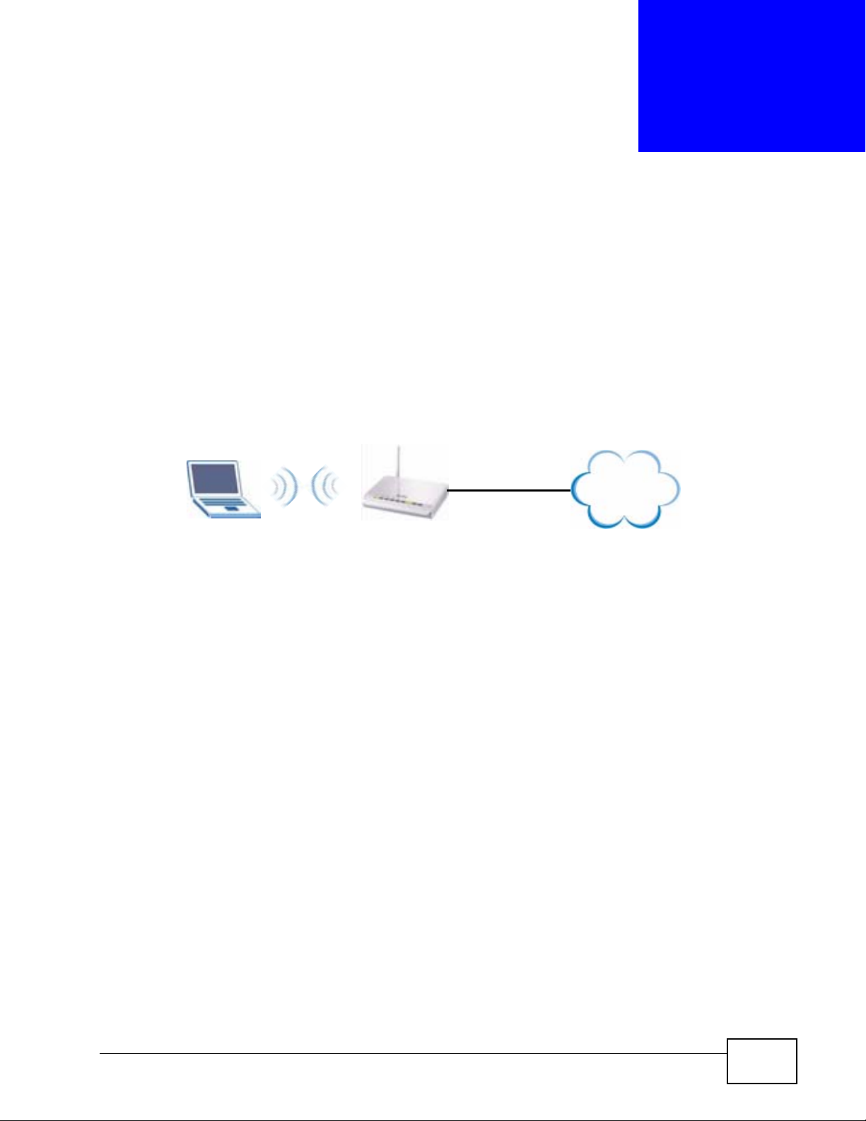
CHAPTER 6
Wireless Tutorial
6.1 How to Connect to the Internet from an AP
This section gives you an example of how to set up an access point (AP) and
wireless client (a notebook (B), in this example) for wireless communication. B
can access the Internet through the AP wirelessly.
Figure 45 Wireless AP Connection to the Internet
B
AP
Internet
6.2 Configure Wireless Security Using WPS on
both your P-320W v3 and Wireless Client
This section gives you an example of how to set up wireless network using WPS.
This example uses the P-320W v3 as the AP and NWD210N as the wireless client
which connects to a notebook.
Note: The wireless client must be a WPS-aware device (for example, a WPS USB
adapter or PCI card).
There are two WPS methods for creating a secure connection. This tutorial shows
you how to do both.
• Push Button Configuration (PBC) - create a secure wireless network simply
by pressing a button. See Section 6.2.1 on page 78.This is the easier method.
• PIN Configuration - create a secure wireless network simply by entering a
wireless client's PIN (Personal Identification Number) in the P-320W v3’s
interface. See Section 6.2.2 on page 79. This is the more secure method, since
one device can authenticate the other.
P-320W v3 User’s Guide
77
Page 78

Chapter 6 Wireless Tutorial
6.2.1 Push Button Configuration (PBC)
1 Make sure that your P-320W v3 is turned on and that it is within range of your
computer.
2 Make sure that you have installed the wireless client (this example uses the
NWD210N) driver and utility in your notebook.
3 In the wireless client utility, find the WPS settings. Enable WPS and press the WPS
button (Start or WPS button)
4 Log into P-320W v3’s web configurator and press the Push Button button in the
Network > Wireless Client > WPS Station screen.
Note: Your P-320W v3 has a WPS button located on its panel, as well as a WPS
button in its configuration utility. Both buttons have exactly the same function;
you can use one or the other.
Note: It doesn’t matter which button is pressed first. You must press the second
button within two minutes of pressing the first one.
The P-320W v3 sends the proper configuration settings to the wireless client. This
may take up to two minutes. Then the wireless client is able to communicate with
the P-320W v3 securely.
78
P-320W v3 User’s Guide
Page 79

Chapter 6 Wireless Tutorial
The following figure shows you an example to set up wireless network and security
by pressing a button on both P-320W v3 and wireless client (the NWD210N in this
example).
Figure 46 Example WPS Process: PBC Method
Wireless Client
SECURITY INFO
COMMUNICATION
P-320W V3
WITHIN 2 MINUTES
6.2.2 PIN Configuration
When you use the PIN configuration method, you need to use both P-320W v3’s
configuration interface and the client’s utilities.
1 Launch your wireless client’s configuration utility. go to the WPS settings and
select the PIN method to get a PIN number.
2 Enter the PIN number to the PIN field in the Network > Wireless LAN > WPS
Station screen on the P-320W v3.
3 Click Start buttons (or button next to the PIN field) on both the wireless client
utility screen and the P-320W v3’s WPS Station screen within two minutes.
The P-320W v3 authenticates the wireless client and sends the proper
configuration settings to the wireless client. This may take up to two minutes.
Then the wireless client is able to communicate with the P-320W v3 securely.
P-320W v3 User’s Guide
79
Page 80

Chapter 6 Wireless Tutorial
The following figure shows you the example to set up wireless network and
security on P-320W v3 and wireless client (ex. NWD210N in this example) by
using PIN method.
Figure 47 Example WPS Process: PIN Method
Wireless Client
P-320W v3
WITHIN 2 MINUTES
80
Authentication by PIN
SECURITY INFO
COMMUNICATION
P-320W v3 User’s Guide
Page 81

Chapter 6 Wireless Tutorial
6.3 Enable and Configure Wireless Security
without WPS on your P-320W v3
This example shows you how to configure wireless security settings with the
following parameters on your P-320W v3.
SSID SSID_Example3
Channel 6
Security WPA-PSK
(Pre-Shared Key: ThisismyWPA-PSKpre-sharedkey)
Follow the steps below to configure the wireless settings on your P-320W v3.
The instructions require that your hardware is connected (see the Quick Start
Guide) and you are logged into the web configurator through your LAN connection
(see Section 2.2 on page 25).
1 Open the Wireless LAN > General screen in the AP’s web configurator.
2 Make sure the Enable Wireless LAN check box is selected.
3 Enter SSID_Example3 as the SSID and select a channel.
Note: To comply with US FCC regulation, the country selection function has been
completely removed from all US models. The above function is for non-US
models only.
4 Set security mode to WPA-PSK and enter ThisismyWPA-PSKpre-sharedkey in
the Pre-Shared Key field. Click Apply.
Figure 48 Network > Wireless LAN > General
P-320W v3 User’s Guide
81
Page 82

Chapter 6 Wireless Tutorial
5 Open the Status screen. Verify your wireless and wireless security settings under
Device Information.
Figure 49 Status: AP Mode
6.4 Configure Your Notebook
Note: We use the ZyXEL M-302 wireless adapter utility screens as an example for the
wireless client. The screens may vary for different models.
1 The P-320W v3 supports IEEE 802.11b and IEEE 802.11g wireless clients. Make
sure that your notebook or computer’s wireless adapter supports one of these
standards.
2 Wireless adapters come with software sometimes called a “utility” that you install
on your computer. See your wireless adapter’s User’s Guide for information on
how to do that.
3 After you’ve installed the utility, open it. If you cannot see your utility’s icon on
your screen, go to Start > Programs and click on your utility in the list of
programs that appears. The utility displays a list of APs within range, as shown in
the example screen below.
82
P-320W v3 User’s Guide
Page 83

Chapter 6 Wireless Tutorial
4 Select SSID_Example3 and click Connect.
Figure 50 Connecting a Wireless Client to a Wireless Network t
5 Select WPA-PSK and type the security key in the following screen. Click Next.
Figure 51 Security Settings
6 The Confirm Save window appears. Check your settings and click Save to
continue.
Figure 52 Confirm Save
P-320W v3 User’s Guide
83
Page 84

Chapter 6 Wireless Tutorial
7 Check the status of your wireless connection in the screen below. If your wireless
connection is weak or you have no connection, see the Troubleshooting section of
this User’s Guide.
Figure 53 Link Status
8 If your connection is successful, open your Internet browser and enter http://
www.zyxel.com or the URL of any other web site in the address bar. If you are able
to access the web site, your wireless connection is successfully configured.
84
P-320W v3 User’s Guide
Page 85

CHAPTER 7
LAN
7.1 Overview
This chapter describes how to configure LAN settings.
A Local Area Network (LAN) is a shared communication system to which many
computers are attached. A LAN is a computer network limited to the immediate
area, usually the same building or floor of a building. The LAN screen can help you
identify your local network.
Figure 54 Local Area Network
LAN
7.2 What You Can Do
Use the LAN IP screen (Section 7.4 on page 87) to change your basic LAN
settings.
7.3 What You Need to Know
DSL
Internet
The following sections provide information that you may need when configuring
the LAN IP screen.
P-320W v3 User’s Guide
85
Page 86

Chapter 7 LAN
7.3.1 IP Pool Setup
The P-320W v3 is pre-configured with a pool of 32 IP addresses starting from
192.168.1.33 to 192.168.1.64. This configuration leaves 31 IP addresses
(excluding the P-320W v3 itself) in the lower range (192.168.1.2 to
192.168.1.32) for other server computers, for instance, servers for mail, FTP,
TFTP, web, etc., that you may have.
7.3.2 System DNS Servers
Refer to Section 3.4.6 on page 48 in the Connection Wizard chapter.
7.3.3 LAN TCP/IP
The P-320W v3 has built-in DHCP server capability that assigns IP addresses and
DNS servers to systems that support DHCP client capability.
7.3.4 Factory LAN Defaults
The LAN parameters of the P-320W v3 are preset in the factory with the following
values:
• IP address of 192.168.1.1 with subnet mask of 255.255.255.0 (24 bits)
• DHCP server enabled with 32 client IP addresses starting from 192.168.1.33.
These parameters should work for the majority of installations. If your ISP gives
you explicit DNS server address(es), read the embedded web configurator help
regarding what fields need to be configured.
7.3.5 IP Address and Subnet Mask
Refer to the IP address and subnet mask section in the Connection Wizard
chapter for this information.
86
P-320W v3 User’s Guide
Page 87

7.4 LAN IP Screen
Use this screen to change your basic LAN settings. Click Network > LAN.
Figure 55 Network > LAN > IP
The following table describes the labels in this screen.
Table 35 Network > LAN > IP
LABEL DESCRIPTION
IP Address Type the IP address of your P-320W v3 in dotted decimal notation
192.168.1.1 (factory default).
IP Subnet Mask The subnet mask specifies the network number portion of an IP
address. Your P-320W v3 will automatically calculate the subnet mask
based on the IP address that you assign. Unless you are implementing
subnetting, use the subnet mask computed by the P-320W v3.
Apply Click Apply to save your changes back to the P-320W v3.
Reset Click Reset to begin configuring this screen afresh.
Chapter 7 LAN
P-320W v3 User’s Guide
87
Page 88

Chapter 7 LAN
88
P-320W v3 User’s Guide
Page 89

CHAPTER 8
DHCP Server
8.1 Overview
DHCP (Dynamic Host Configuration Protocol, RFC 2131 and RFC 2132) allows
individual clients to obtain TCP/IP configuration at start-up from a server. You can
configure the P-320W v3’s DHCP server(s) or disable it.
When configured as a server, the P-320W v3 provides the TCP/IP configuration for
the clients. If DHCP service is disabled, you must have another DHCP server on
your LAN or Guest WLAN, or else the computer must be manually configured.
8.2 What You Can Do
•Use the DHCP Server General screen (Section 8.3 on page 89) to enable and
configure your DHCP server.
•Use the Static DHCP screen (Section 8.4 on page 91) to change your P-320W
v3’s Static DHCP settings.
•Use the Client List screen (Section 8.5 on page 91) to view a list of current
DHCP client information.
8.3 DHCP Server General Screen
Use this screen to enable and configure your DHCP server.
P-320W v3 User’s Guide
89
Page 90

Chapter 8 DHCP Server
Click Network > DHCP Server. The following screen displays.
Figure 56 Network > DHCP Server > General
The following table describes the labels in this screen.
Table 36 Network > DHCP Server > General
LABEL DESCRIPTION
Enable DHCP
Server
Leave the check box selected unless your ISP instructs you to do
otherwise. Clear it to disable the P-320W v3 acting as a DHCP
server.
When configured as a server, the P-320W v3 provides TCP/IP
configuration for the clients. If not, DHCP service is disabled and
you must have another DHCP server on your LAN, or else the
computers must be manually configured.
IP Pool Starting
Address
Pool Size This field specifies the size, or count of the IP address pool.
Lease Time Select how long a computer can lease its IP address in the network.
DNS Servers
The P-320W v3 passes a DNS (Domain Name System) server IP address (in the order you
specify here) to the DHCP clients. The P-320W v3 only passes this information to the LAN
DHCP clients when you select the Enable DHCP Server check box. When you clear the
Enable DHCP Server check box, DHCP service is disabled and you must have another
DHCP sever on your LAN, or else the computers must have their DNS server addresses
manually configured.
First DNS Server
Second DNS Server
Apply Click Apply to save your changes back to the P-320W v3.
Reset Click Reset to begin configuring this screen afresh.
This field specifies the first of the contiguous addresses in the IP
address pool.
You can select from 1 HOUR (default) to as long as Forever
(unlimited time).
Enter the IP address(es) of the DNS server(s). If you do not
configure a DNS server, you must know the IP address of a
computer in order to access it.
90
P-320W v3 User’s Guide
Page 91

8.4 Static DHCP Screen
This table allows you to assign IP addresses on the LAN to specific individual
computers based on their MAC addresses.
Every Ethernet device has a unique MAC (Media Access Control) address. The MAC
address is assigned at the factory and consists of six pairs of hexadecimal
characters, for example, 00-A0-C5-00-00-02.
To change your P-320W v3’s Static DHCP settings, click the DHCP Server link
under Network and the Static DHCP tab. The following screen displays.
Figure 57 Network > DHCP Server > Advanced
Chapter 8 DHCP Server
The following table describes the labels in this screen.
Table 37 Network > DHCP Server > Advanced
LABEL DESCRIPTION
# This is the index number of the static IP table entry (row).
MAC Address Type the MAC address (with colons) of a computer on your LAN.
IP Address Type the LAN IP address of a computer on your LAN.
Apply Click Apply to save your changes back to the P-320W v3.
Reset Click Reset to begin configuring this screen afresh.
8.5 Client List Screen
The DHCP table shows current DHCP client information (including IP Address,
Host Name and MAC Address) of LAN or Guest WLAN network clients using the
P-320W v3’s DHCP servers.
P-320W v3 User’s Guide
91
Page 92

Chapter 8 DHCP Server
Configure this screen to always assign an IP address to a MAC address (and host
name). Click Network > DHCP Server > Client List.
Note: You can also view a read-only client list by clicking the DHCP Table (Details...)
hyperlink in the Status screen.
The following screen displays.
Figure 58 Network > DHCP Server > Client List
The following table describes the labels in this screen.
Table 38 Network > DHCP Server > Client List
LABEL DESCRIPTION
# This is the index number of the host computer.
IP Address This field displays the IP address relative to the # field listed above.
Host Name This field displays the computer host name.
MAC Address The MAC (Media Access Control) or Ethernet address on a LAN
(Local Area Network) is unique to your computer (six pairs of
hexadecimal notation).
A network interface card such as an Ethernet adapter has a
hardwired address that is assigned at the factory. This address
follows an industry standard that ensures no other adapter has a
similar address.
Reserve Select this check box in the LAN DHCP Setup or Guest WLAN
DHCP Setup section to have the P-320W v3 always assign the IP
address(es) to the MAC address(es) (and host name(s)). After you
click Apply, the MAC address and IP address also display in the
Advanced screen (where you can edit them).
Apply Click Apply to save your settings.
Refresh Click Refresh to reload the DHCP table.
92
P-320W v3 User’s Guide
Page 93

CHAPTER 9
Network Address Translation
(NAT)
9.1 Overview
This chapter discusses how to configure NAT on the P-320W v3.
NAT (Network Address Translation - NAT, RFC 1631) is the translation of the IP
address of a host in a packet. For example, the source address of an outgoing
packet, used within one network is changed to a different IP address known within
another network.
9.2 What You Can Do
•Use the General NAT screen (Section 9.4 on page 96) to enable NAT on your P320W v3.
•Use the Port Forwarding screen (Section 9.5 on page 97) to define the local
servers to which the incoming services will be forwarded.
•Use the Trigger Port screen (Section 9.3.2 on page 95) change your P-320W
v3’s trigger port settings.
9.3 What You Need to Know
The following section provides information on how you can properly configure NAT.
Note: You must create a firewall rule in addition to setting up NAT, to allow traffic from
the WAN to be forwarded through the P-320W v3.
9.3.1 Port Forwarding: Services and Port Numbers
A port forwarding set is a list of inside (behind NAT on the LAN) servers, for
example, web or FTP, that you can make accessible to the outside world even
P-320W v3 User’s Guide
93
Page 94

Chapter 9 Network Address Translation (NAT)
though NAT makes your whole inside network appear as a single machine to the
outside world.
Use the Application screen to forward incoming service requests to the server(s)
on your local network. You may enter a single port number or a range of port
numbers to be forwarded, and the local IP address of the desired server. The port
number identifies a service; for example, web service is on port 80 and FTP on
port 21. In some cases, such as for unknown services or where one server can
support more than one service (for example both FTP and web service), it might
be better to specify a range of port numbers.
In addition to the servers for specified services, NAT supports a default server. A
service request that does not have a server explicitly designated for it is forwarded
to the default server. If the default is not defined, the service request is simply
discarded.
Note: Many residential broadband ISP accounts do not allow you to run any server
processes (such as a Web or FTP server) from your location. Your ISP may
periodically check for servers and may suspend your account if it discovers any
active services at your location. If you are unsure, refer to your ISP.
9.3.1.1 Configuring Servers Behind Port Forwarding Example
Let's say you want to assign ports 21-25 to one FTP, Telnet and SMTP server (A in
the example), port 80 to another (B in the example) and assign a default server IP
address of 192.168.1.35 to a third (C in the example). You assign the LAN IP
addresses and the ISP assigns the WAN IP address. The NAT network appears as a
single host on the Internet
Figure 59 Multiple Servers Behind NAT Example
WAN
A=192.168.1.33
B=192.168.1.34
LAN
192.168.1.1
Internet
C=192.168.1.35
192.168.1.36
9.3.2 Trigger Port Forwarding
Some services use a dedicated range of ports on the client side and a dedicated
range of ports on the server side. With regular port forwarding you set a
forwarding port in NAT to forward a service (coming in from the server on the
94
P-320W v3 User’s Guide
Page 95

Chapter 9 Network Address Translation (NAT)
WAN) to the IP address of a computer on the client side (LAN). The problem is
that port forwarding only forwards a service to a single LAN IP address. In order to
use the same service on a different LAN computer, you have to manually replace
the LAN computer's IP address in the forwarding port with another LAN
computer's IP address.
Trigger port forwarding solves this problem by allowing computers on the LAN to
dynamically take turns using the service. The P-320W v3 records the IP address of
a LAN computer that sends traffic to the WAN to request a service with a specific
port number and protocol (a "trigger" port). When the P-320W v3's WAN port
receives a response with a specific port number and protocol ("incoming" port),
the P-320W v3 forwards the traffic to the LAN IP address of the computer that
sent the request. After that computer’s connection for that service closes, another
computer on the LAN can use the service in the same manner. This way you do not
need to configure a new IP address each time you want a different LAN computer
to use the application.
9.3.2.1 Trigger Port Forwarding Example
The following is an example of trigger port forwarding.
Figure 60 Trigger Port Forwarding Process: Example
Jane’s computer
Real Audio Server
Port 7070
Internet
1 Jane requests a file from the Real Audio server (port 7070).
2 Port 7070 is a “trigger” port and causes the P-320W v3 to record Jane’s computer
IP address. The P-320W v3 associates Jane's computer IP address with the
"incoming" port range of 6970-7170.
3 The Real Audio server responds using a port number ranging between 6970-7170.
4 The P-320W v3 forwards the traffic to Jane’s computer IP address.
5 Only Jane can connect to the Real Audio server until the connection is closed or
times out. The P-320W v3 times out in three minutes with UDP (User Datagram
Protocol), or two hours with TCP/IP (Transfer Control Protocol/Internet Protocol).
P-320W v3 User’s Guide
95
Page 96

Chapter 9 Network Address Translation (NAT)
9.3.3 Two Points To Remember About Trigger Ports
1 Trigger events only happen on data that is going coming from inside the P-320W
v3 and going to the outside.
2 If an application needs a continuous data stream, that port (range) will be tied up
so that another computer on the LAN can’t trigger it.
9.4 General NAT Screen
Use this screen to enable NAT on your P-320W v3.
Click Network > NAT to open the General screen.
Figure 61 Network > NAT > General
The following table describes the labels in this screen.
Table 39 Network > NAT > General
LABEL DESCRIPTION
Enable Network
Address
Translation
Apply Click Apply to save your changes back to the P-320W v3.
Reset Click Reset to begin configuring this screen afresh.
Network Address Translation (NAT) allows the translation of an Internet
protocol address used within one network (for example a private IP
address used in a local network) to a different IP address known within
another network (for example a public IP address used on the Internet).
Select the check box to enable NAT.
9.5 Port Forwarding Screen
Port forwarding allows you to define the local servers to which the incoming
services will be forwarded. To change your P-320W v3’s port forwarding settings,
click Network > NAT > Application. The screen appears as shown.
96
P-320W v3 User’s Guide
Page 97

Chapter 9 Network Address Translation (NAT)
Note: If you do not assign a Default Server IP address in the NAT > General screen,
the P-320W v3 discards all packets received for ports that are not specified in
this screen or remote management.
Refer to Appendix E on page 247 for port numbers commonly used for particular
services.
Figure 62 Network > NAT > Application
The following table describes the labels in this screen.
Table 40 NAT Application
LABEL DESCRIPTION
Default Server Setup
Default Server Type the inside IP address of the server that receives packets from the
port(s) that are not specified in the Port field.
Port Forwarding
# This is the number of an individual port forwarding server entry.
Active This icon is turned on when the rule is enabled.
Name This field displays a name to identify this rule.
Start Port This field displays a start port number.
End Port This field displays an end port number. If the same port number as the
Start Port is displayed then a single port is forwarded. If a different
number to the Start Port number is displayed then a range of ports are
forwarded.
Server IP
Address
This field displays the inside IP address of the server.
P-320W v3 User’s Guide
97
Page 98

Chapter 9 Network Address Translation (NAT)
Table 40 NAT Application (continued)
LABEL DESCRIPTION
Modify Click the Edit icon to display and modify an existing rule setting in the
fields under Add Application Rule.
Click the Remove icon to delete a rule.
Apply Click Apply to save your changes to the Application Rules Summary
table.
Reset Click Reset to not save and return your new changes in the Service
Name and Port fields to the previous one.
9.5.1 Rule Setup Screen
To edit a port forwarding rule, click the edit icon under Modify. The following
screen displays.
Figure 63 NAT: Port Forwarding: Rule Setup
The following table describes the labels in this screen.
Table 41 Network > NAT > General
LABEL DESCRIPTION
Active Select the check box to enable this port forwarding entry.
Clear the checkbox to disallow forwarding of these ports to an inside
server without having to delete the entry.
Service Name Type a Service Name to identify this port-forwarding rule.
Start Port Type a start port number. To forward only one port, enter it again in the
End Port field. To specify a range of ports, enter the last port to be
forwarded in the End Port field.
End Port Type an end port number.
Server IP
Address
Apply Click Apply to save your changes back to the P-320W v3.
Reset Click Reset to begin configuring this screen afresh.
Type the inside IP address of the server.
98
P-320W v3 User’s Guide
Page 99

9.6 Trigger Port Screen
To change your P-320W v3’s trigger port settings, click Network > NAT >
Advanced. The screen appears as shown.
Note: Only one LAN computer can use a trigger port (range) at a time.
Figure 64 Network > NAT > Advanced
Chapter 9 Network Address Translation (NAT)
The following table describes the labels in this screen.
Table 42 Network > NAT > Advanced
LABEL DESCRIPTION
# This is the rule index number (read-only).
Name Type a unique name (up to 15 characters) for identification purposes. All
characters are permitted - including spaces.
Incoming Incoming is a port (or a range of ports) that a server on the WAN uses
when it sends out a particular service. The P-320W v3 forwards the
traffic with this port (or range of ports) to the client computer on the
LAN that requested the service.
Start Port Type a port number or the starting port number in a range of port
numbers.
End Port Type a port number or the ending port number in a range of port
numbers.
Trigg e r The trigger port is a port (or a range of ports) that causes (or triggers)
the P-320W v3 to record the IP address of the LAN computer that sent
the traffic to a server on the WAN.
Start Port Type a port number or the starting port number in a range of port
numbers.
P-320W v3 User’s Guide
99
Page 100

Chapter 9 Network Address Translation (NAT)
Table 42 Network > NAT > Advanced
LABEL DESCRIPTION
End Port Type a port number or the ending port number in a range of port
numbers.
Apply Click Apply to save your changes back to the P-320W v3.
Reset Click Reset to begin configuring this screen afresh.
9.7 Technical Reference
This section provides some technical information about the topics covered in this
chapter.
9.7.1 Game List Example
Here is an example game list text file. The index number, service name and
associated port(s) are specified by semi-colons (no spaces). Use the name=xxx
(where xxx is the service name) to create a new service. Port range can be
separated with a hyphen (-) (no spaces). Multiple (non-consecutive) ports can be
separated by commas.
Figure 65 Game List Example
version=1
1;name=Battlefield 1942;port=14567,22000,23000-23009,27900,28900
2;name=Call of Duty;port=28960
3;name=Civilization IV;port=2056
4;name=Diablo I and II;port=6112-6119,4000
5;name=Doom 3;port=27666
6;name=F.E.A.R;port=27888
7;name=Final Fantasy XI;port=25,80,110,443,50000-65535
8;name=Guild Wars;port=6112,80
9;name=Half Life;port=6003,7002,27005,27010,27011,27015
10;name=Jedi Knight III: Jedi Academy;port=28060-28062,28070-28081
11;name=Need for Speed: Hot Pursuit 2;port=1230,8511-
8512,27900,28900,61200-61230
12;name=Neverwinter Nights;port=5120-5300,6500,27900,28900
13;name=Quake 2;port=27910
14;name=Quake 3;port=27660,27960
15;name=Rainbow Six 3: Raven Shield;port=7777-7787,8777-8787
16;name=Serious Sam II;port=25600-25605
17;name=Silent Hunter III;port=17997-18003
18;name=Soldier of Fortune II;port=20100-20112
19;name=Starcraft;port=6112-6119,4000
20;name=Star Trek: Elite Force II;port=29250,29256
21;name=SWAT 4;port=10480-10483
22;name=Warcraft II and III;port=6112-6119,4000
23;name=World of Warcraft;port=3724
100
P-320W v3 User’s Guide
 Loading...