

Chapter 15 Certificates
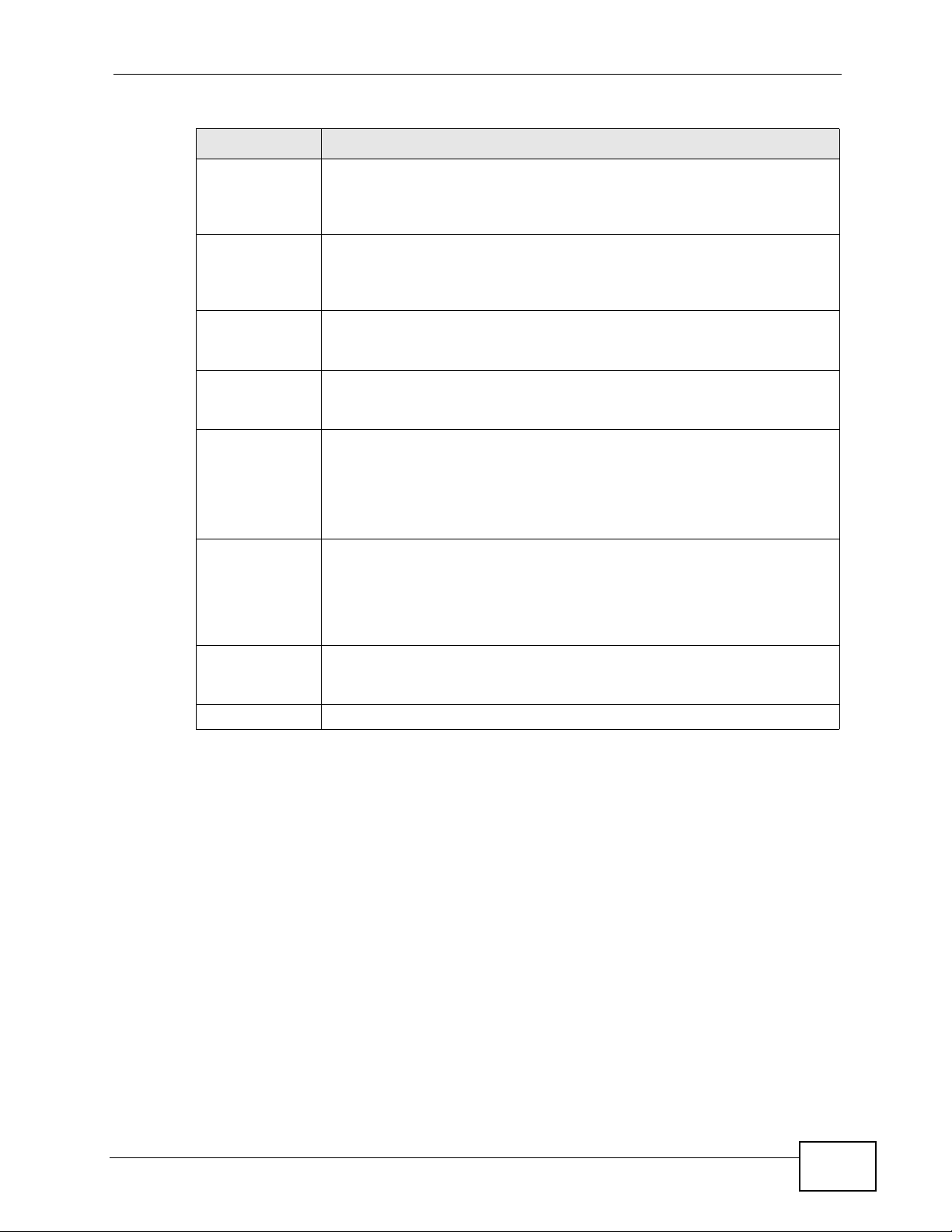
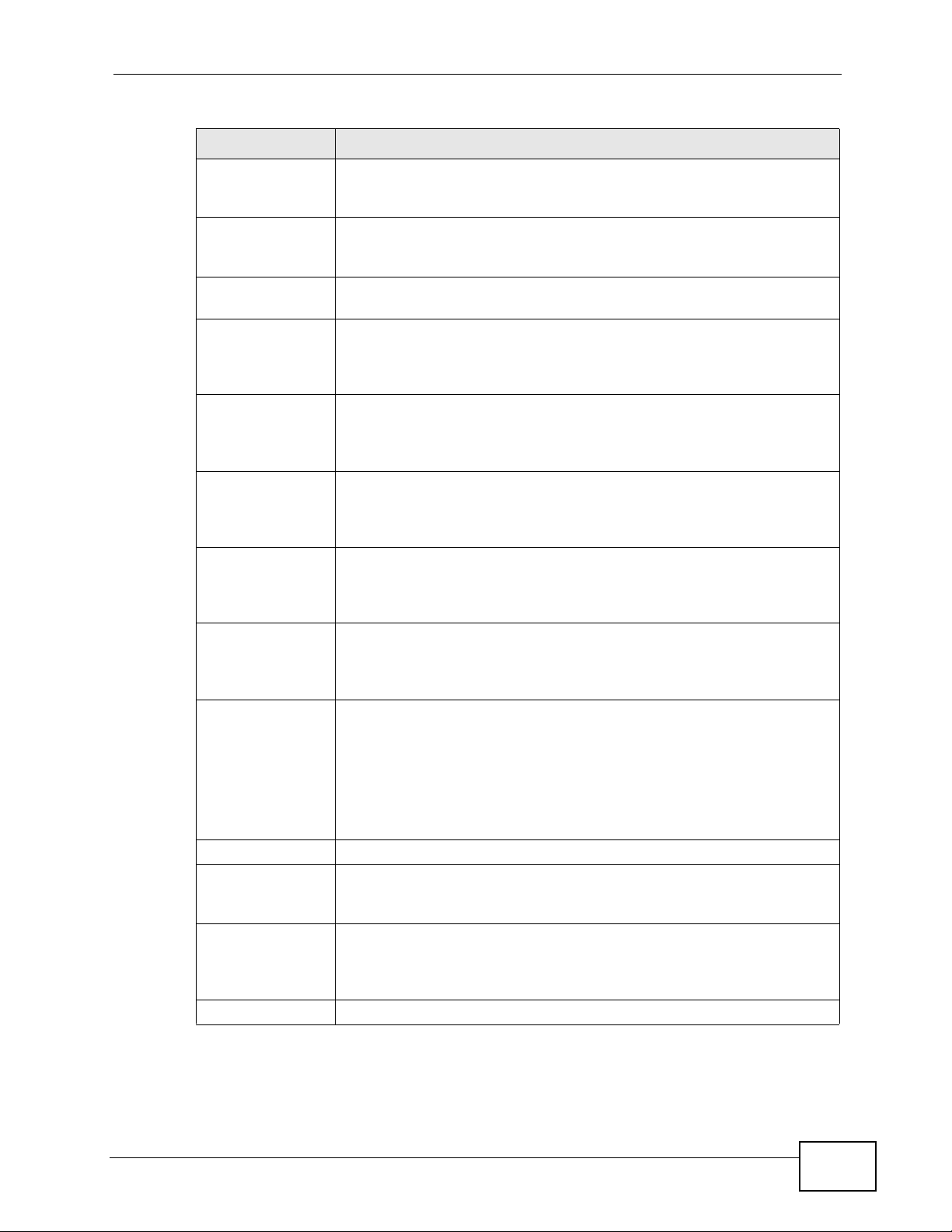
Table 96 Security > Certificates > Trusted CAs (continued)
LABEL DESCRIPTION
Subject This field displays identifying information about the certificate’s owner,
such as CN (Common Name), OU (Organizational Unit or department),
O (Organization or company) and C (Country). It is recommended that
each certificate have unique subject information.
Issuer This field displays identifying information about the certificate’s issuing
certification authority, such as a common name, organizational unit or
department, organization or company and country. With self-signed
certificates, this is the same information as in the Subject field.
Valid From This field displays the date that the certificate becomes applicable. The
text displays in red and includes a Not Yet Valid! message if the
certificate has not yet become applicable.
Valid To This field displays the date that the certificate expires. The text displays
in red and includes an Expiring! or Expired! message if the certificate is
about to expire or has already expired.
CRL Issuer This field displays Yes if the certification authority issues Certificate
Revocation Lists for the certificates that it has issued and you have
selected the Issues certificate revocation lists (CRL) check box in
the certificate’s details screen to have the ZyXEL Device check the CRL
before trusting any certificates issued by the certification authority.
Otherwise the field displays “No”.
Modify Click the Edit icon to open a screen with an in-depth list of information
about the certificate.
Click the Remove icon to remove the certificate. A window displays
asking you to confirm that you want to delete the certificates. Note that
subsequent certificates move up by one when you take this action.
Import Click Import to open a screen where you can save the certificate of a
certification authority that you trust, from your computer to the ZyXEL
Device.
Refresh Click this button to display the current validity status of the certificates.
15.6 Trusted CA Import
Click Security > Certificates > Trusted CAs to open the Trusted CAs screen
and then click Import to open the Trusted CA Import screen. Follow the
instructions in this screen to save a trusted certification authority’s certificate to
the ZyXEL Device.
P-2612HWU-F1 User’s Guide
301
Chapter 15 Certificates
Note: You must remove any spaces from the certificate’s filename before you can
import the certificate.
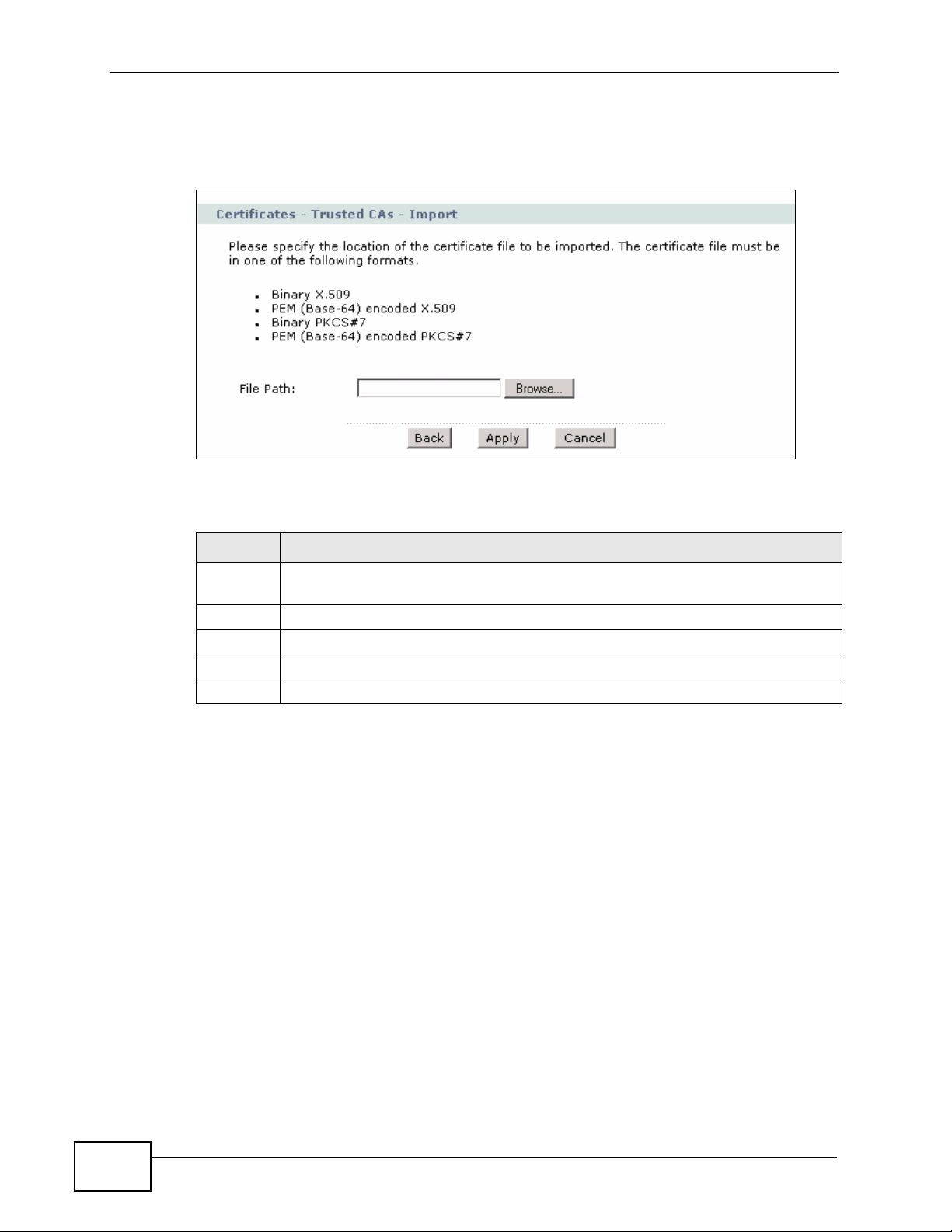
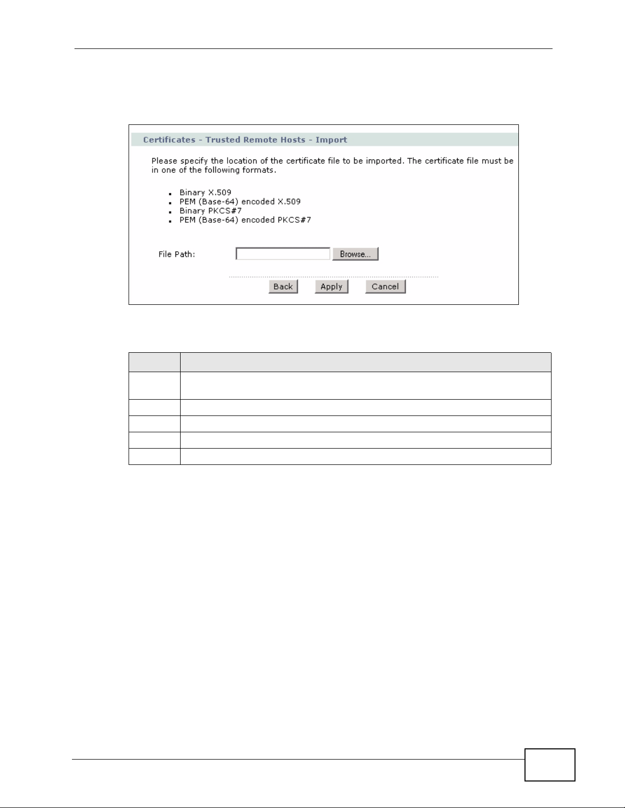
Figure 179 Security > Certificates > Trusted CA > Import
The following table describes the labels in this screen.
Table 97 Security > Certificates > Trusted CA > Import
LABEL DESCRIPTION
File Path Type in the location of the file you want to upload in this field or click Browse
to find it.
Browse Click Browse to find the certificate file you want to upload.
Back Click Back to return to the previous screen.
Apply Click Apply to save the certificate on the ZyXEL Device.
Cancel Click Cancel to quit and return to the Trusted CAs screen.
15.7 Trusted CA Details
Click Security > Certificates > Trusted CAs to open the Trusted CAs screen.
Click the details icon to open the Trusted CA Details screen. Use this screen to
view in-depth information about the certification authority’s cert ificate, change the
certificate’s name and set whether or not you want the ZyXEL Device to check a
302
P-2612HWU-F1 User’s Guide
Chapter 15 Certificates
certification authority’s list of revoked certificates before trusting a certificate
issued by the certification authority.
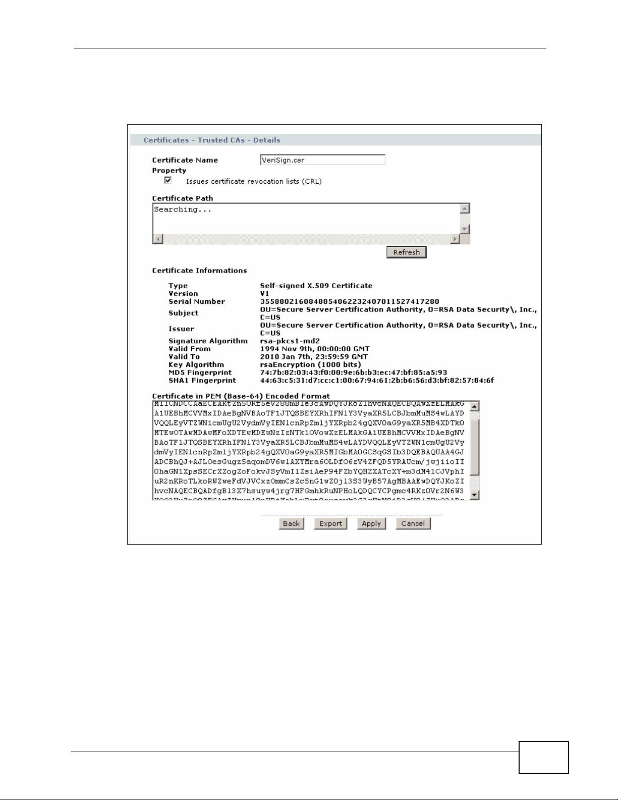
Figure 180 Security > Certificates > Trusted CA > Details
P-2612HWU-F1 User’s Guide
303
Chapter 15 Certificates
The following table describes the labels in this screen.
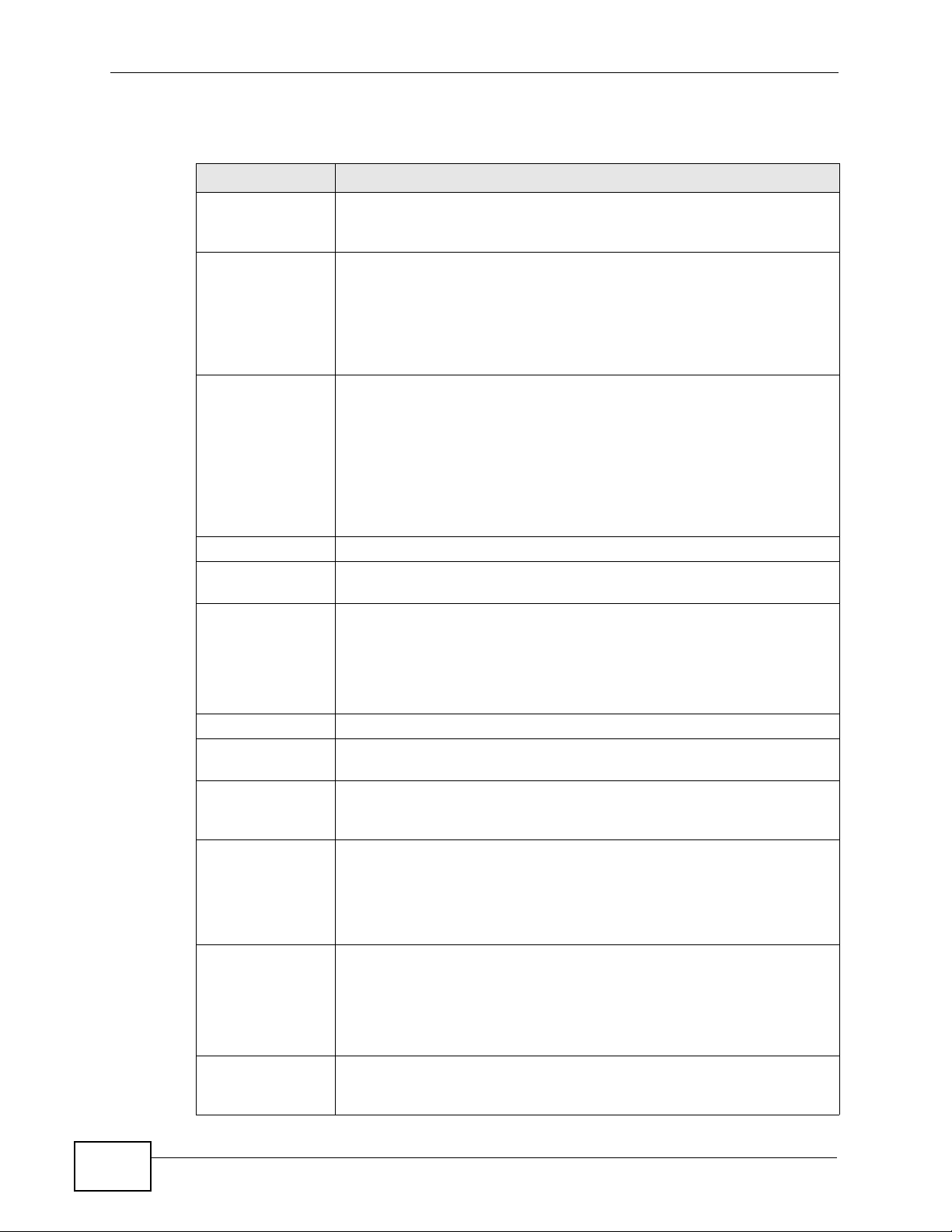
Table 98 Security > Certificates > Trusted CA > Details
LABEL DESCRIPTION
Certificate Name This field displays the identifying name of this certificate. If you want
Property
Issues certificate
revocation lists
(CRLs)
Certificate Path Click the Refresh button to have this read-only text box display the
Refresh Click Refresh to display the certification path.
Certificate
Information
T ype This field displays general information about the certificate. CA-signed
Version This field displays the X.509 version number.
Serial Number This fie ld displays the certificate’s identification number given by the
Subject This field displays information that identifies the owner of the
Issuer This field displays identifying information about the certificate’s
to change the name, type up to 31 characters to identify this key
certificate. You may use any character (not including spaces).
Select this check box to have the ZyXEL Device check incoming
certificates that are issued by this certification authority against a
Certificate Revocation List (CRL).
Clear this check box to have the ZyXEL Device not check incoming
certificates that are issued by this certification authority against a
Certificate Revocation List (CRL).
end entity’s certificate and a list of certification authority certificates
that shows the hierarchy of certification authorities that validate the
end entity’s certificate. If the issuing certification authority is one that
you have imported as a trusted certification authority, it may be the
only certification authority in the list (along with the end entity’s own
certificate). The ZyXEL Device does not trust the end entity’s
certificate and displays “Not trusted” in this field if any certificate on
the path has expired or been revoked.
These read-only fields display detailed information about the
certificate.
means that a Certification Authority signed the certificate. Self-signed
means that the certificate’s owner signed the certificate (not a
certification authority). X.509 means that this certificate was created
and signed according to the ITU-T X.509 recommendation that
defines the formats for public-key certificates.
certification authority.
certificate, such as Common Name (CN), Organizational Unit (OU),
Organization (O) and Country (C).
issuing certification authority , such as Common Name, Organizational
Unit, Organization and Country.
304
With self-signed certificates, this is the same information as in the
Subject Name field.
Signature
Algorithm
Valid From This field displays the date that the certificate becomes applicable.
This field displays the type of algorithm that was used to sign the
certificate. Some certification authorities use rsa-pkcs1-sha1 (RSA
public-private key encryption algorithm and the SHA1 hash
algorithm). Other certification authorities may use rsa-pkcs1-md5
(RSA public-private key encryption algorithm and the MD5 hash
algorithm).
The text displays in red and includes a Not Yet Valid! message if the
certificate has not yet become applicable.
P-2612HWU-F1 User’s Guide
Chapter 15 Certificates
Table 98 Security > Certificates > Trusted CA > Details (continued)
LABEL DESCRIPTION
Valid To This field displays the date that the certificate expires. The text
displays in red and includes an Expiring! or Expired! message if the
certificate is about to expire or has already expired.
Key Algorithm This field displays the type of algorithm that was used to gener ate the
certificate’s key pair (the Z yXEL Device uses RS A encryption) and the
length of the key set in bits (1024 bits for example).
Subject
Alternative Name
Key Usage This field displays for what functions the certificate’s key can be used.
Basic Constraint This field displays general information about the certificate. For
CRL Distribution
Points
MD5 Fingerprint This is the certificate’s message digest that the ZyXEL Device
SHA1 Fingerprint This is the certificate’s message digest that the ZyXEL Device
Certificate in PEM
(Base-64)
Encoded Format
This field displays the certificate’s owner‘s IP address (IP), domain
name (DNS) or e-mail address (EMAIL).
For example, “DigitalSignature” means that the key can be used to
sign certificates and “KeyEncipherment” means that the key can be
used to encrypt text.
example, Subject Type=CA means that this is a certification
authority’s certificate and “Path Length Constraint=1” means that
there can only be one certification authority in the certificate’s path.
This field displays how many directory servers with Lists of revoked
certificates the issuing certification authority of this certificate makes
available. This field also displays the domain names or IP addresses of
the servers.
calculated using the MD5 algorithm. You can use this value to verify
with the certification authority (over the phone for example) that this
is actually their certificate.
calculated using the SHA1 algorithm. You can use this value to verify
with the certification authority (over the phone for example) that this
is actually their certificate.
This read-only text box displays the certificate or certification request
in Privacy Enhanced Mail (PEM) format. PEM uses 64 ASCII characters
to convert the binary certificate into a printable form.
Back Click Back to return to the previous screen.
Export Click this button and then Save in the File Download screen. The
Apply Click Apply to save your changes back to the ZyXEL Device. You can
Cancel Click Cancel to quit and return to the Trusted CAs screen.
P-2612HWU-F1 User’s Guide
You can copy and paste the certificate into an e-mail to send to
friends or colleagues or you can copy and paste the certificate into a
text editor and save the file on a management computer for later
distribution (via floppy disk for example).
Save As screen opens, browse to the location that you want to use
and click Save.
only change the name and/or set whether or not you want the ZyXEL
Device to check the CRL that the certification authority issues before
trusting a certificate issued by the certification authority.
305
Chapter 15 Certificates
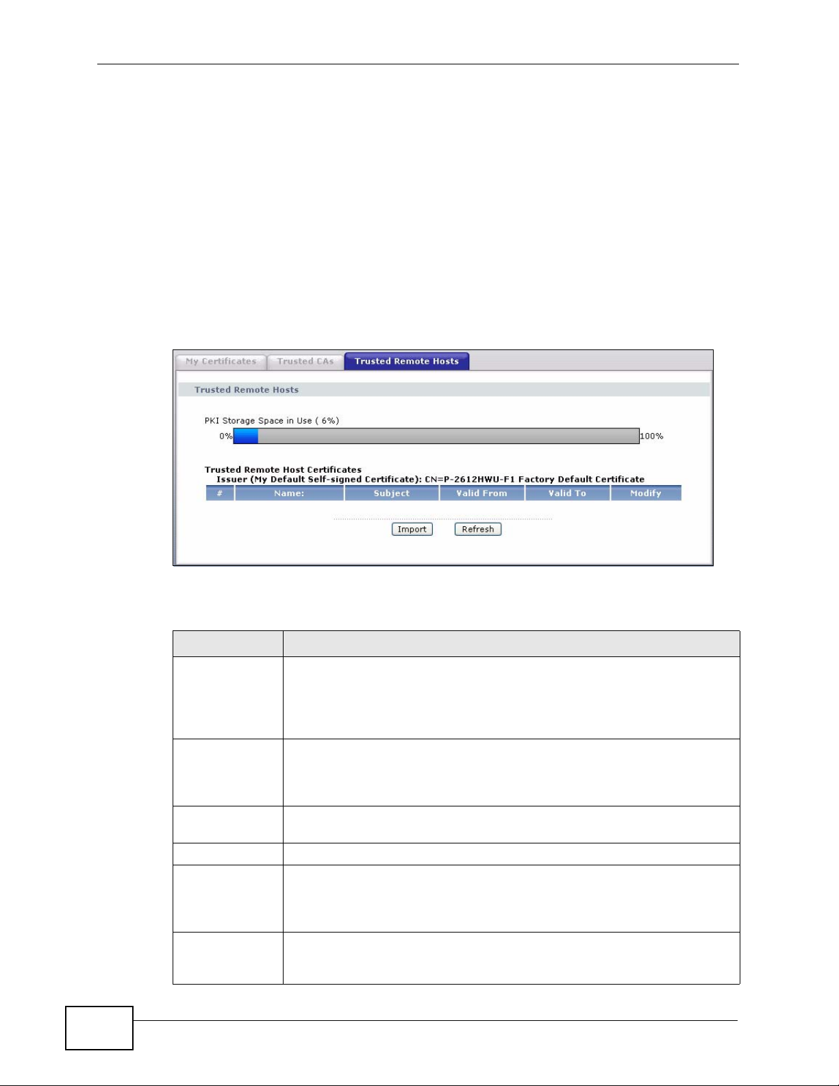
15.8 Trusted Remote Hosts
Click Security > Certificates > Trusted Remote Hosts to open the Trusted
Remote Hosts screen. This screen displays a list of the certificates of peers that
you trust but which are not signed by one of the certification authorities on the
Trusted CAs screen.
You do not need to add any certificate that is signed by one of the certification
authorities on the Trusted CAs screen since the ZyXEL Device automatically
accepts any valid certificate signed by a trusted certification authority as being
trustworthy.
Figure 181 Security > Certificates > Trusted Remote Hosts
The following table describes the labels in this screen.
Table 99 Security > Certificates > Trusted Remote Hosts
LABEL DESCRIPTION
PKI Storage
Space in Use
Issuer (My
Default Selfsigned
Certificate)
# This field displays the certificate index number. The certificates are
Name This field displays the name used to identify this certificate.
Subject This field displays identifying information about the certificate’s owner,
Valid From This field displays the date that the certificate becomes applicable. The
This bar displays the percentage of the ZyXEL Device’s PKI storage
space that is currently in use. The bar turns from green to red when the
maximum is being approached. When the bar is red, you should
consider deleting expired or unnecessary certificates before adding
more certificates.
This field displays identifying information about the default self-signed
certificate on the ZyXEL Device that the ZyXEL Device uses to sign the
trusted remote host certificates.
listed in alphabetical order.
such as CN (Common Name), OU (Organizational Unit or department),
O (Organization or company) and C (Country). It is recommended that
each certificate have unique subject information.
text displays in red and includes a Not Yet Valid! message if the
certificate has not yet become applicable.
306
P-2612HWU-F1 User’s Guide
Chapter 15 Certificates
Table 99 Security > Certificates > Trusted Remote Hosts (continued)
LABEL DESCRIPTION
Valid T o This field displays the date that the certificate expires. The text displays
in red and includes an Expiring! or Expired! message if the certificate is
about to expire or has already expired.
Modify Click the Edit icon to open a screen with an in-depth list of information
about the certificate.
Click the Remove icon to remove the certificate. A window displays
asking you to confirm that you want to delete the certificate. Note that
subsequent certificates move up by one when you take this action.
Import Click Import to open a screen where you can save the certificate of a
remote host (which you trust) from your computer to the ZyXEL Device.
Refresh Click this button to display the current validity status of the certificates.
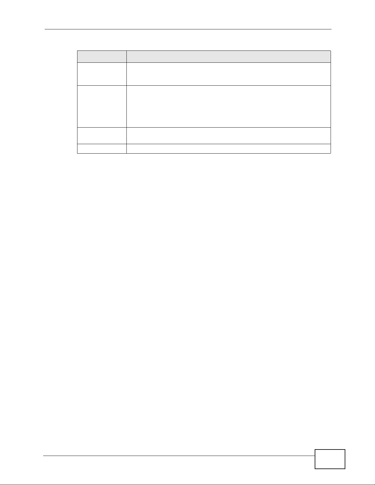
15.9 Trusted Remote Host Certificate Details
Click Security > Certificates > Trusted Remote Hosts to open the Trusted
Remote Hosts screen. Click the details icon to open the Trusted Remote Host
P-2612HWU-F1 User’s Guide
307
Chapter 15 Certificates
Details screen. Use this screen to view in-depth information about the trusted
remote host’s certificate and/or change the certificate’s name.
Figure 182 Security > Certificates > Trusted Remote Hosts > Details
308
The following table describes the labels in this screen.
Table 100 Security > Certificates > Trusted Remote Hosts > Details
LABEL DESCRIPTION
Certificate Name This field displays the identifying name of this certificate. If you want
to change the name, type up to 31 characters to identify this key
certificate. You may use any character (not including spaces).
Certificate Path Click the Refresh button to have this read-only text box display the
end entity’s own certificate and a list of certification authority
certificates in the hierarchy of certification authorities that validate a
certificate’s issuing certification authority. For a trusted host, the list
consists of the end entity’s own certificate and the default self-signed
certificate that the ZyXEL Device uses to sign remote host
certificates.
Refresh Click Refresh to display the certification path.
P-2612HWU-F1 User’s Guide
Chapter 15 Certificates
Table 100 Security > Certificates > Trusted Remote Hosts > Details (continued)
LABEL DESCRIPTION
Certificate Path These read-only fields display detailed information about the
certificate.
Type This field displays general information about the certificate. With
trusted remote host certificates, this field always displays CA-signed.
The ZyXEL Device is the Certification Authority that signed the
certificate. X.509 means that this certificate was created and signed
according to the ITU-T X.509 recommendation that defines the
formats for public-key certificates.
Version This field displays the X.509 version number.
Serial Number This field displays the certificate’s identification number given by the
device that created the certificate.
Subject This field displays information that identifies the owner of the
certificate, such as Common Name (CN), Organizational Unit (OU),
Organization (O) and Country (C).
Issuer This field displays identifying information about the default self-
signed certificate on the ZyXEL Device that the ZyXEL Device uses to
sign the trusted remote host certificates.
Signature
Algorithm
Valid From This field displays the date that the certificate becomes applicable.
Valid To This field displays the date that the certificate expires. The text
Key Algorithm This field displays the type of algorithm that was used to generate
Subject Alternative
Name
Key Usage This field displays for what functions the certificate’s key can be
Basic Constraint This field displays general information about the certificate. For
MD5 Fingerprint This is the certificate’s message digest that the ZyXEL Device
This field displays the type of algorithm that the ZyXEL Device used
to sign the certificate, which is rsa-pkcs1-sha1 (RSA public-private
key encryption algorithm and the SHA1 hash algorithm).
The text displays in red and includes a Not Yet Valid! message if the
certificate has not yet become applicable.
displays in red and includes an Expiring! or Expired! message if the
certificate is about to expire or has already expired.
the certificate’s key pair (the ZyXEL Device uses RSA encryption) and
the length of the key set in bits (1024 bits for example).
This field displays the certificate’s owner‘s IP address (IP), domain
name (DNS) or e-mail address (EMAIL).
used. For example, “Digit al S i gn ature” means that the key can be
used to sign certificates and “KeyEncipherment” means that the key
can be used to encrypt text.
example, Subject Type=CA means that this is a certification
authority’s certificate and “Path Length Constraint=1” means that
there can only be one certification authority in the certificate’s path.
calculated using the MD5 algorithm. You cannot use this value to
verify that this is the remote host’s actual certificate because the
ZyXEL Device has signed the certificate; thus causing this value to
be different from that of the remote hosts actual certificate. See
Section 15.1.3 on page 289 for how to verify a remote host’s
certificate.
P-2612HWU-F1 User’s Guide
309
Chapter 15 Certificates
Table 100 Security > Certificates > Trusted Remote Hosts > Details (continued)
LABEL DESCRIPTION
SHA1 Fingerprint This is the certificate’s message digest that the ZyXEL Device
Certificate in PEM
(Base-64) Encoded
Format
Back Click Back to return to the previous screen.
Export Click this button and then Save in the File Download screen. The
Apply Click Apply to save your changes back to the Z yXEL Device. You can
Cancel Click Cancel to quit configuring this screen and return to the
calculated using the SHA1 algorithm. You cannot use this value to
verify that this is the remote host’s actual certificate because the
ZyXEL Device has signed the certificate; thus causing this value to
be different from that of the remote hosts actual certificate. See
Section 15.1.3 on page 289 for how to verify a remote host’s
certificate.
This read-only text box displays the certificate or certification
request in Privacy Enhanced Mail (PEM) format. PEM uses 64 ASCII
characters to convert the binary certificate into a printable form.
You can copy and paste the certificate into an e-mail to send to
friends or colleagues or you can copy and paste the certificate into a
text editor and save the file on a management computer for later
distribution (via floppy disk for example).
Save As screen opens, browse to the location that you want to use
and click Save.
only change the name of the certificate.
Trusted Remote Hosts screen.
15.10 Trusted Remote Hosts Import
Click Security > Certificates > Trusted Remote Hosts to open the Trusted
Remote Hosts screen and then click Import to open the Trusted Remote Host
Import screen. Follow the instructions in this screen to save a trusted host’s
certificate to the ZyXEL Device.
310
P-2612HWU-F1 User’s Guide
Chapter 15 Certificates
Note: The trusted remote host certificate must be a self-signed certificate; and you
must remove any spaces from its filename before you can import it.
Figure 183 Security > Certificates > Trusted Remote Hosts > Import
The following table describes the labels in this screen.
Table 101 Security > Certificates > Trusted Remote Hosts > Import
LABEL DESCRIPTION
File Path Type in the location of the file you want to upload in this field or click Browse
to find it.
Browse Click Browse to find the certificate file you want to upload.
Back Click Back to return to the previous screen.
Apply Click Apply to save the certificate on the ZyXEL Device.
Cancel Click Cancel to quit and return to the Trusted Remote Hosts screen.
P-2612HWU-F1 User’s Guide
311

Chapter 15 Certificates
312
P-2612HWU-F1 User’s Guide
CHAPTER 16
Static Route
16.1 Overview
The ZyXEL Device usually uses the default gateway to route outbound tr affic from
computers on the LAN to the Internet. To have the ZyXEL Device send data to
devices not reachable through the default gateway, use static routes.
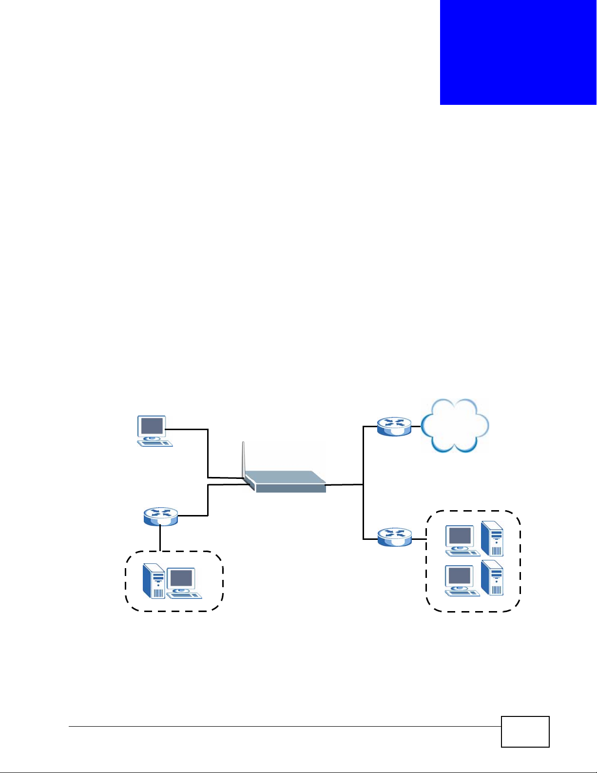
For example, the next figure shows a computer (A) connected to the ZyXEL
Device’s LAN interface. The ZyXEL Device routes most traffic from A to the
Internet through the ZyXEL Device’s default gateway (R1). You create one static
route to connect to services offered by your ISP behind router R2. You create
another static route to communicate with a separate network behind a router R3
connected to the LAN.
Figure 184 Example of Static Routing Topology
A
R3
LAN
WAN
R1
Internet
R2
16.1.1 What You Can Do in the Static Route Screens
Use the Static Route screens (Section 16.2 on page 314) to view and configure
IP static routes on the ZyXEL Device.
P-2612HWU-F1 User’s Guide
313

Chapter 16 Static Route
16.2 Configuring Static Route
Click Advanced > Static Route to open the Static Route screen.
Figure 185 Advanced > Static Route
The following table describes the labels in this screen.
Table 102 Advanced > Static Route
LABEL DESCRIPTION
# This is the number of an individual static route.
Active This field indicates whether the rule is active or not.
Clear the check box to disable the rule. Select the check box to enable it.
Name This is the name that describes or identifies this route.
Destination This parameter specifies the IP network address of the final destination.
Routing is always based on network number.
Netmask This parameter specifies the IP network subnet mask of the final
destination.
Gateway This is the IP address of the gateway. The gateway is a router or switch
on the same network segment as the device's LAN or WAN port. The
gateway helps forward packets to their destinations.
Modify Click the Edit icon to go to the screen where you can set up a static route
on the ZyXEL Device.
Click the Remove icon to remove a static route from the ZyXEL Device. A
window displays asking you to confirm that you want to delete the route.
Apply Click this to apply your changes to the ZyXEL Device.
Cancel Click this to return to the previously saved configuration.
314
P-2612HWU-F1 User’s Guide
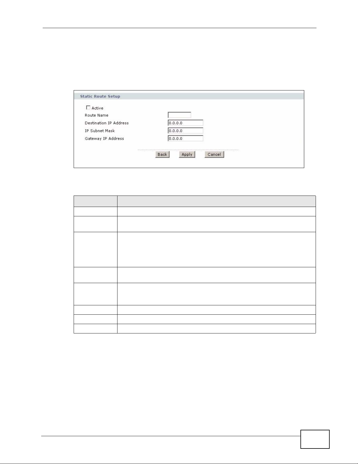
16.2.1 Static Route Edit
Select a static route index number and click Edit. The screen shown next appears.
Use this screen to configure the required information for a static route.
Figure 186 Advanced > Static Route > Edit
The following table describes the labels in this screen.
Table 103 Advanced > Static Route > Edit
LABEL DESCRIPTION
Active This field allows you to activate/deactivate this static route.
Route Name Enter the name of the IP static route. Leave this field blank to delete this
static route.
Destination IP
Address
IP Subnet
Mask
Gateway IP
Address
Back Click Back to return to the previous screen without saving.
Apply Click Apply to save your changes back to the ZyXEL Device.
Cancel Click Cancel to begin configuring this screen afresh.
This parameter specifies the IP network address of the final destination.
Routing is always based on network number. If you need to specify a
route to a single host, use a subnet mask of 255.255.255.255 in the
subnet mask field to force the network number to be identical to the host
ID.
Enter the IP subnet mask here.
Enter the IP address of the gateway. The gateway is a router or switch on
the same network segment as the device's LAN or WAN port. The
gateway helps forward packets to their destinations.
Chapter 16 Static Route
P-2612HWU-F1 User’s Guide
315

Chapter 16 Static Route
316
P-2612HWU-F1 User’s Guide
CHAPTER 17
802.1Q/1P
17.1 Overview
A Virtual Local Area Network (VLAN) allows a physical network to be partitioned
into multiple logical networks. A VLAN group can be treated as an individual
device. Each group can have its own rules about where and how to forward traffic.
You can assign any ports on the ZyXEL Device to a VLAN group and configure the
settings for the group. You may also set the priority level for traffic transmitted
through the ports.
Figure 187 802.1Q/1P
Ports
802.1Q
VLAN Groups
802.1P
Priority Levels
17.1.1 What You Can Do in the 802.1Q/1P Screens
•Use the Group Setting screen (Section 17.2 on page 324) to activate 802.1Q/
1P, specify the management VLAN group, display the VLAN groups and
configure the settings for each VLAN group.
•Use the Port Setting screen (Section 17.3 on page 327) to configure the PVID
and assign traffic priority for each port.
17.1.2 What You Need to Know About 802.1Q/1P
IEEE 802.1P Priority
IEEE 802.1P specifies the user priority field and defines up to eight separate tr affic
types by inserting a tag into a MAC-layer fr ame that contains bits to define class of
service.
P-2612HWU-F1 User’s Guide
317

Chapter 17 802.1Q/1P
IEEE 802.1Q Tagged VLAN
Tagged VLAN uses an explicit tag (VLAN ID) in the MAC header to identify the
VLAN membership of a frame across bridges - they are not confined to the device
on which they were created. The VLA N ID associates a fr ame with a speci fic VLAN
and provides the information that devices need to process the frame across the
network.
PVC
A virtual circuit is a logical point-to-point circuit between customer sites.
Permanent means that the circuit is preprogrammed by the carrier as a path
through the network. It does not need to be set up or torn down for each session.
Forwarding Tagged and Untagged Frames
Each port on the device is capable of passing tagged or untagged frames. To
forward a frame from an 802.1Q VLAN-aware device t o an 802. 1Q VLAN- unaw are
device, the ZyXEL Device first decides where to f orward the frame and then strips
off the VLAN tag. To forward a frame from an 802.1Q VLAN-unaware device to an
802.1Q VLAN-aware switch, the ZyXEL Device first decides where to forward the
frame, and then inserts a VLAN tag reflecting the ingress port's default VID. The
default PVID is VLAN 1 for all ports, but this can be changed.
Whether to tag an outgoing frame depends on the setting of the egress port on a
per-VLAN, per-port basis (recall that a port can belong to multiple VLANs). If the
tagging on the egress port is enabled for the VID of a frame, then the frame is
transmitted as a tagged frame; otherwise, it is transmitted as an untagged frame.
318
P-2612HWU-F1 User’s Guide
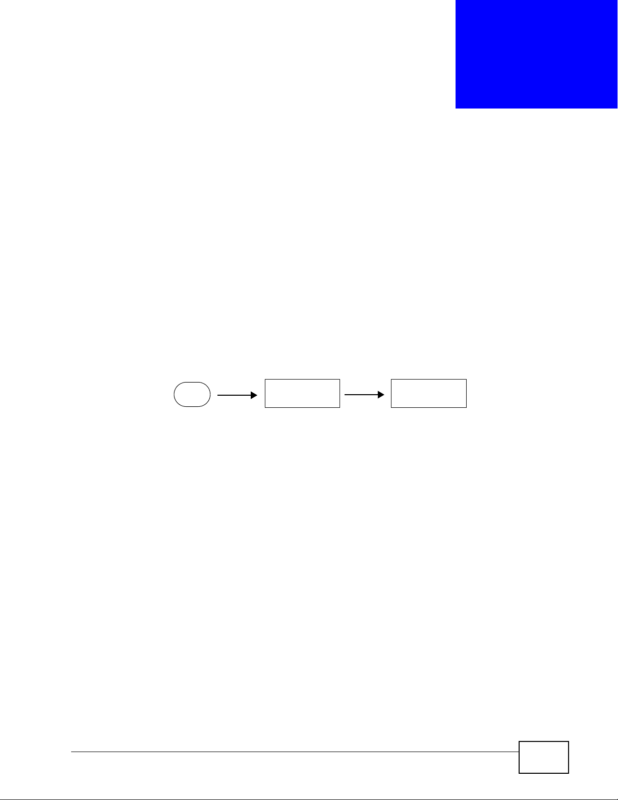
17.1.3 802.1Q/1P Example
This example shows how to configure the 802.1Q/1P settings on the ZyXEL
Device.
Figure 188 802.1Q/1P Example
Chapter 17 802.1Q/1P
ZyXEL Device
1
2
3
4
LAN1 and LAN2 are connected to ATAs (Analog Telephone Adapters) and used for
VoIP tr affic. Y ou w ant to set a high priority for this type of tr affic, so you will group
these ports into one VLAN (VLAN2) and then set them to use a PVC (PVC1) with a
high priority service level. You would start with the following steps.
1
2
3
4
5
6
7
8
VoIP Network
Internet - (PPPoE)
Internet - (PPPoE)
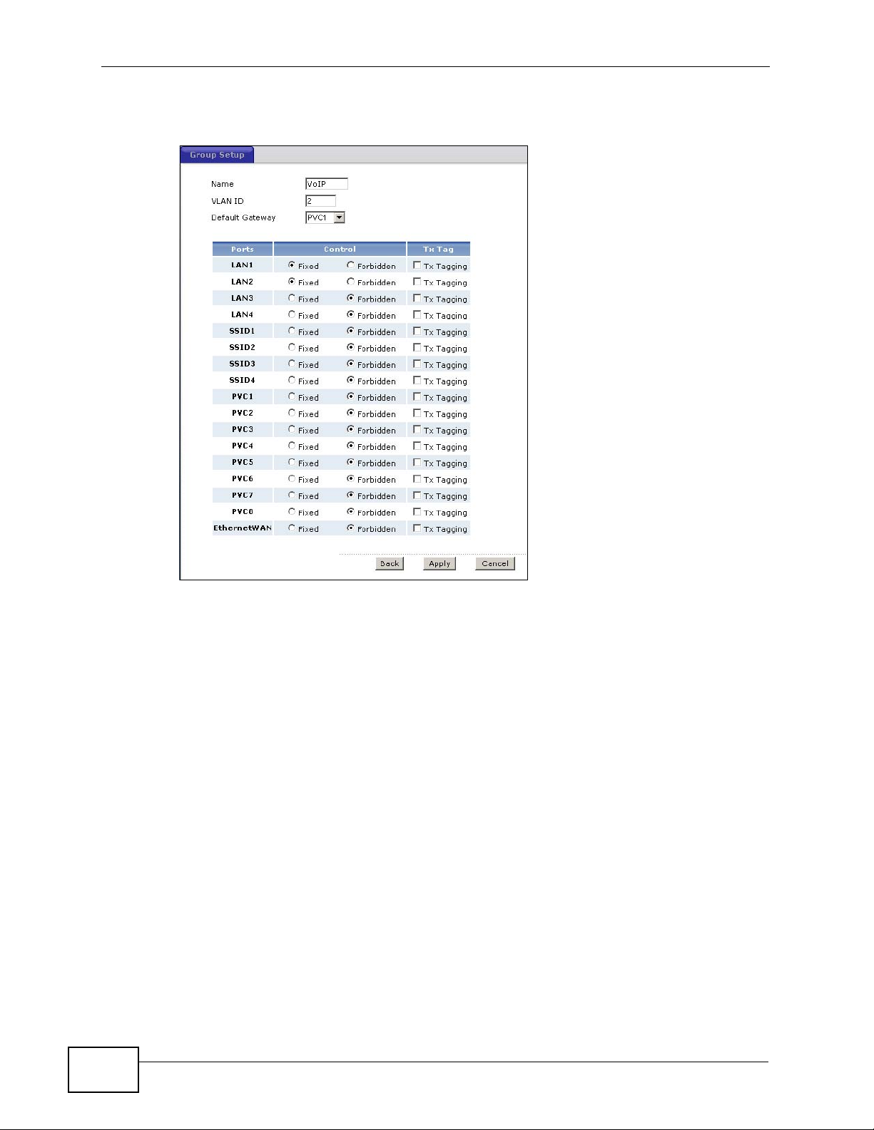
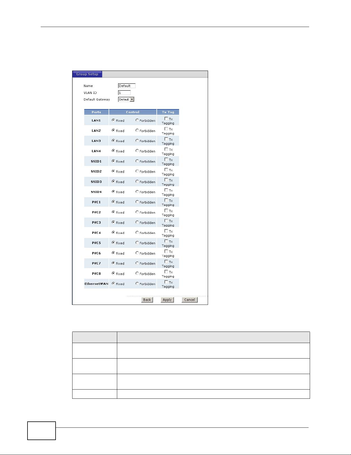
1 Click Advanced > 802.1Q/1P > Group Setting > Edit to display the following
screen.
2 In the Name field type VoIP to identify the group.
3 In the VLAN ID field type in 2 to identify the VLAN grou p.
4 Select PVC1 from the Default Gateway drop-down list box.
5 In the Control field, select Fixed for LAN1, LAN2 and PVC1 to be permanent
members of the VLAN group.
P-2612HWU-F1 User’s Guide
319
Chapter 17 802.1Q/1P
6 Click Apply.
Figure 189 Advanced > 802.1Q/1P > Group Setting > Edit: Example
To set a high priority for VoIP traffic, follow these steps.
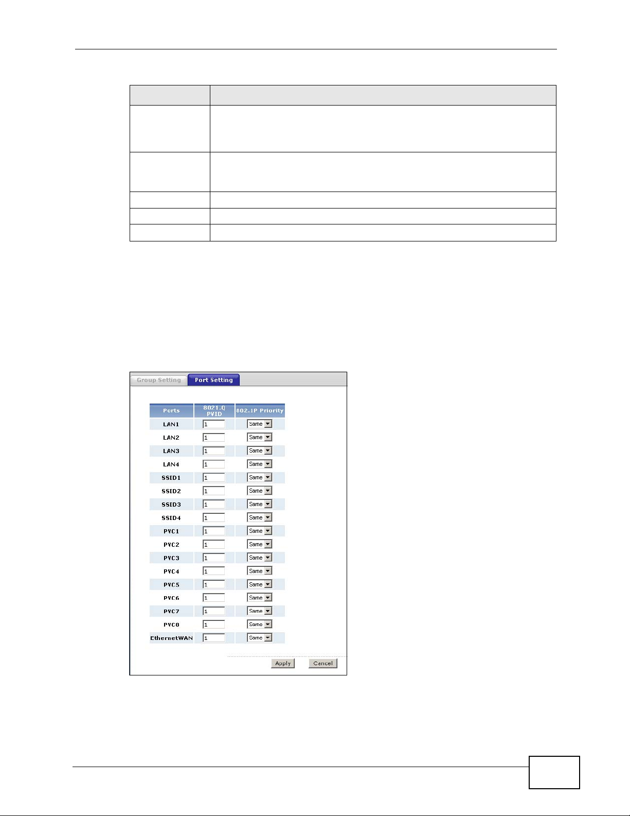
1 Click Advanced > 802.1Q/1P > Port Setting to display the following screen.
2 Type 2 in the 802.1Q PVID column for LAN1, LAN2 and PV C1.
3 Select 7 from the 802.1P Priority drop-down list box for LAN1, LAN2 and PVC1.
320
P-2612HWU-F1 User’s Guide

4 Click Apply.
Figure 190 Advanced > 802.1Q/1P > Port Setting: Example
Chapter 17 802.1Q/1P
Ports 3 and 4 are connected to desktop computers and are used for Internet
traffic. Y ou want to set a l ower priority for this type of tr affic, so you want to group
these ports and PVC2 into one VLAN (VLAN3). PVC2 priority is set to low level of
service.
SSID1 an d SSID2 are two wireless netwo rks. You want to create medium priority
for this type of traffic, so you want to group these ports and PVC3 into one VLAN
(VLAN4). PVC3 priority is set to medium level of service.
P-2612HWU-F1 User’s Guide
321
Chapter 17 802.1Q/1P
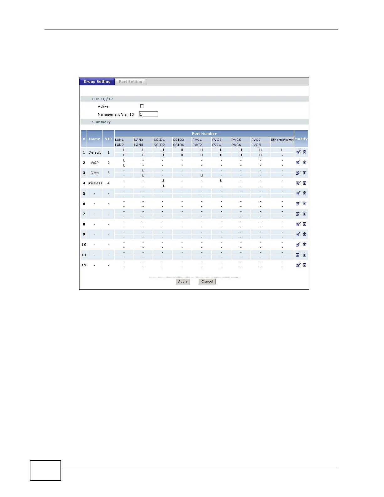
Follow the same steps as in VLAN2 to configure the settings for VLAN3 and VLAN4.
The summary screen should display as follows.
Figure 191 Advanced > 802.1Q/1P > Group Setting: Example
322
P-2612HWU-F1 User’s Guide
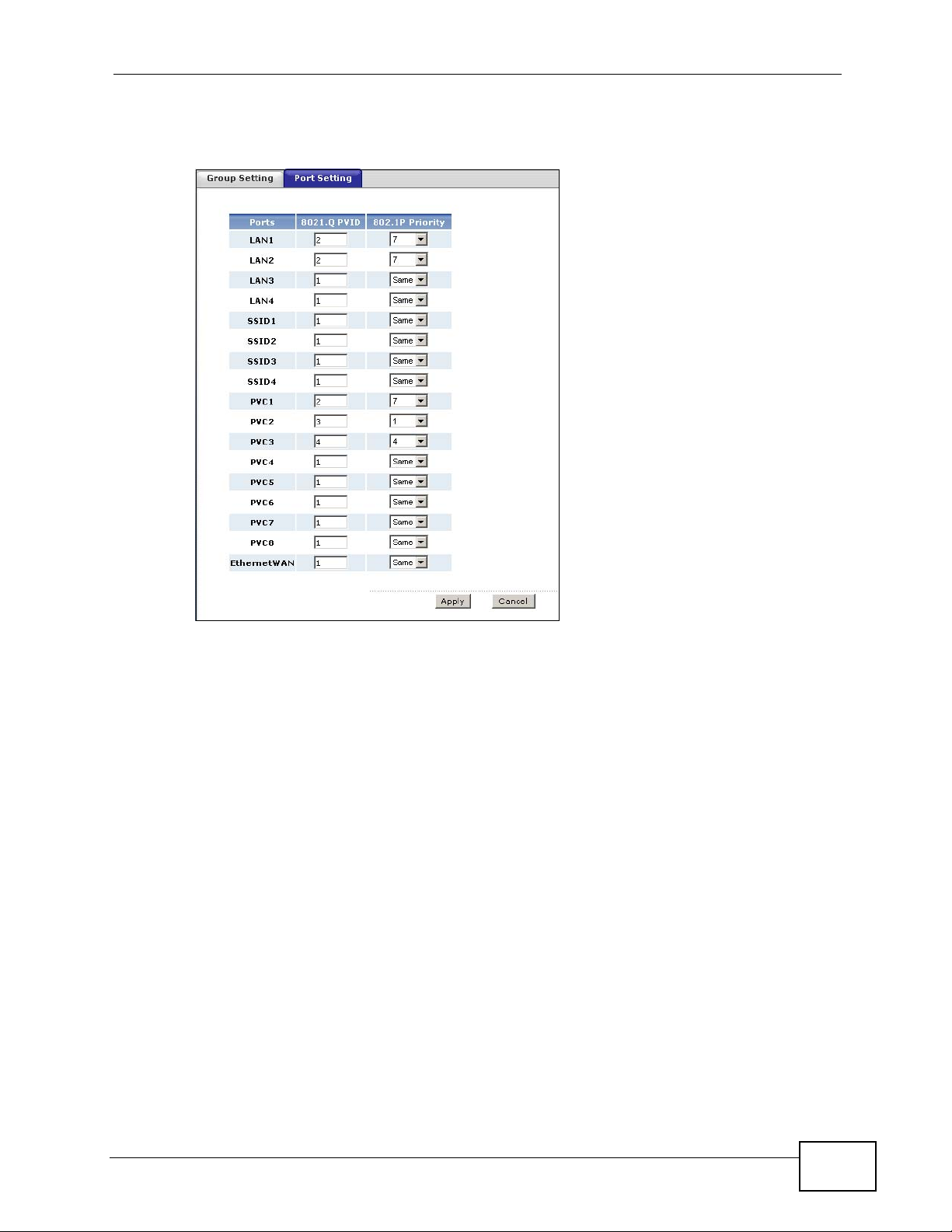
The port screen should look like this.
Figure 192 Advanced > 802.1Q/1P > Port Setting: Example
Chapter 17 802.1Q/1P
This completes the 802.1Q/1P setup.
P-2612HWU-F1 User’s Guide
323
Chapter 17 802.1Q/1P
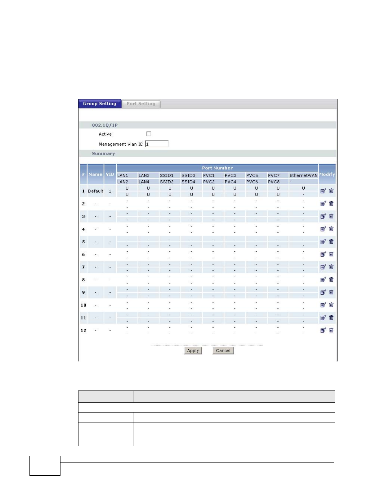
17.2 The 802.1Q/1P Group Setting Screen
Use this screen to activate 802.1Q/1P and display the VLAN groups. Click
Advanced > 802.1Q/1P to display the following screen.
Figure 193 Advanced > 802.1Q/1P > Group Setting
324
The following table describes the labels in this screen.
Table 104 Advanced > 802.1Q/1P > Group Setting
LABEL DESCRIPTION
802.1P/1Q
Active Select this check box to activate the 802.1P/1Q feature.
Management Vlan IDEnter the ID number of a VLAN group. All interfaces (ports, SSIDs and
PVCs) are in the management VLAN by default. If you disable the
management VLAN, you will not be able to access the ZyXEL Device.
P-2612HWU-F1 User’s Guide
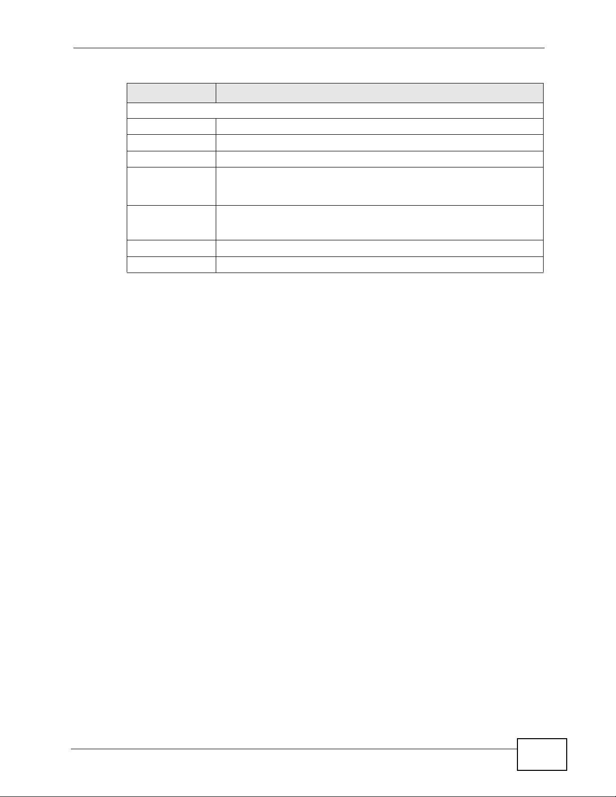
Table 104 Advanced > 802.1Q/1P > Group Setting (continued)
LABEL DESCRIPTION
Summary
# This field displays the index number of the VLAN group.
Name This field displays the name of the VLAN group.
VID This field displays the ID number of the VLAN group.
Port Number These columns display the VLAN’s settings for each port. A tagged
port is marked as T, an untagged port is marked as U and ports not
participating in a VLAN are marked as “–“.
Modify Click the Edit button to configure the ports in the VLAN group.
Click the Remove button to delete the VLAN group.
Apply Click this to save your changes.
Cancel Click this to restore your previously saved settings.
17.2.1 Editing 802.1Q/1P Group Setting
Use this screen to configure the settings for each VLAN group.
Chapter 17 802.1Q/1P
P-2612HWU-F1 User’s Guide
325
Chapter 17 802.1Q/1P
In the 802.1Q/1P screen, click the Edit button from the Modify filed to display
the following screen.
Figure 194 Advanced > 802.1Q/1P > Group Setting > Edit
326
The following table describes the labels in this screen.
Table 105 Advanced > 802.1Q/1P > Group Setting > Edit
LABEL DESCRIPTION
Name Enter a descriptive name for the VLAN group for identification purposes.
The text may consist of up to 8 letters, numerals, “-”, “_” and “@”.
VLAN ID Assign a VLAN ID for the VLAN group. The valid VID range is between 1
and 4094.
Default
Gateway
Ports This field displays the types of ports available to join the VLAN group.
Select the default gateway for the VLAN group.
P-2612HWU-F1 User’s Guide
Chapter 17 802.1Q/1P
Table 105 Advanced > 802.1Q/1P > Group Setting > Edit (continued)
LABEL DESCRIPTION
Control Select Fixed for the port to be a permanent member of the VLAN group.
Select Forbidden if you want to prohibit the port from joining the VLAN
group.
Tx Tag Select Tx Tagging if you want the port to tag all outgoing traffic
transmitted through this VLAN. You select this if you want to create
VLANs across different devices and not just the ZyXEL Device.
Back Click this to return to the previous screen without saving.
Apply Click this to save your changes.
Cancel Click this to restore your previously saved settings.
17.3 The 802.1Q/1P Port Setting Screen
Use this screen to configure the PVID and assign traffic priority for each port. Click
Advanced > 802.1Q/1P > Port Setting to display the following screen.
Figure 195 Advanced > 802.1Q/1P > Port Setting
P-2612HWU-F1 User’s Guide
327
Chapter 17 802.1Q/1P
The following table describes the labels in this screen.
Table 106 Advanced > 802.1Q/1P > Port Setting
LABEL DESCRIPTION
Ports This field displays the types of ports available to join the VLAN group.
802.1Q PVID Assign a VLAN ID for the port. The valid VID range is between 1 and
802.1P Priority Assign a priority for the traffic transmitted through the port, SSID, or
Apply Click this to save your changes.
Cancel Click this to restore your previously saved settings.
4094. The ZyXEL Device assigns the PVID to untagged frames or
priority-tagged frames received on this port, SSID, or PVC.
PVC. Select Same if you do not want to modify the priority. You may
choose a priority level from 0-7, with 0 being the lowest level and 7
being the highest level.
328
P-2612HWU-F1 User’s Guide

CHAPTER 18
Quality of Service (QoS)
This chapter contains information about configuring QoS, editing classifiers and
viewing the ZyXEL Device’s QoS packet statistics.
18.1 Overview
This chapter discusses the ZyXEL Device’s QoS screens. Use these screens to set
up your ZyXEL Device to use QoS for traffic management.
Quality of Service (QoS) refers to both a network’s abilit y to deliver data with
minimum delay, and the networking methods used to control the use of
bandwidth. QoS allows the ZyXEL Device to group and prioritize application tr affic
and fine-tune network performance.
Without QoS, all traffic data is equally likely to be dropped when the network is
congested. This can cause a reduction in network performance and make the
network inadequate for time-critical application such as video-on-demand.
The ZyXEL Device assigns each packet a priority and then queues the packet
accordingly. Packets assigned a high priority are processed more quickly than
those with low priority if there is congestion, allowing time-sensitive applications
to flow more smoothly . T ime-sensitive applications include both those that require
a low level of latency (delay) and a low level of jitter (variations in delay) such as
Voice over IP (VoIP) or Internet gaming, and those for which jitter alone is a
problem such as Internet radio or streaming video.
• See Section 18.5 on page 341 for advanced technical information on SIP.
18.1.1 What You Can Do in the QoS Screens
•Use the General screen (Section 18.2 on page 333) to enable QoS on the
ZyXEL Device, decide allowable bandwidth using QoS and configure priority
mapping settings for traffic that does not match a custom class.
•Use the Class Setup screen (Section 18.3 on page 335) to set up classifiers to
sort traffic into different flows and assign priority and define actions to be
performed for a classified traffic flow.
P-2612HWU-F1 User’s Guide
329

Chapter 18 Quality of Service (QoS)
•Use the Monitor screen (Section 18.4 on page 341) to view the ZyXEL Device’s
QoS-related packet statistics.
18.1.2 What You Need to Know About QoS
QoS versus Cos
QoS is used to prioritize source-to-destination tr affic flows. All packets in the same
flow are given the same priority . CoS ( class of service) is a way of managing tr affic
in a network by grouping similar types of traffic together and treating each t ype as
a class. You can use CoS to give different priorities to different packet types.
CoS technologies include IEEE 802.1p layer 2 tagging and DiffServ (Differentiated
Services or DS). IEEE 802.1p tagging makes use of three bits in the packet
header, while DiffServ is a new protocol and defines a new DS field, which replaces
the eight-bit ToS (Type of Service) field in the IP header.
Tagging and Marking
In a QoS class, you can configure whether to add or change the DSCP (DiffServ
Code Point) value, IEEE 802.1p priority level and VLAN ID number in a matched
packet. When the packet passes through a compatible network, the networking
device, such as a backbone switch, can provide specific treatment or service
based on the tag or marker.
18.1.3 QoS Class Setup Example
In the following figure, your Internet connection has an upstream transmission
speed of 50 Mbps. You configure a classifier to assign the highest priority queue
(6) to VoIP traffic from the LAN interface, so that voice traffic would not get
delayed when there is network congestion. Traffic from the boss’s IP address
(192.168.1.23 for example) is mapped to queue 5. Traffic that does not match
330
P-2612HWU-F1 User’s Guide

Chapter 18 Quality of Service (QoS)
these two classes are assigned priority queue based on the internal QoS mapping
table on the ZyXEL Device.
Figure 196 QoS Example
VoIP: Queue 6
DSL
50 Mbps
Boss: Queue 5
IP=192.168.1.23
Figure 197 QoS Class Example: VoIP -1
Internet
P-2612HWU-F1 User’s Guide
331

Chapter 18 Quality of Service (QoS)
Figure 198 QoS Class Example: VoIP -2
Figure 199 QoS Class Example: Boss -1
332
P-2612HWU-F1 User’s Guide

Figure 200 QoS Class Example: Boss -2
Chapter 18 Quality of Service (QoS)
18.2 The QoS General Screen
Click Advanced > QoS to open the screen as shown next. Use this screen to
enable or disable QoS, and select to have the ZyXEL Device automatically assign
P-2612HWU-F1 User’s Guide
333

Chapter 18 Quality of Service (QoS)
priority to traffic according to the IEEE 802.1p prio rity lev el, IP precedence and/or
packet length.
Figure 201 Advanced > QoS > General
The following table describes the labels in this screen.
Table 107 Advanced > QoS > General
LABEL DESCRIPTION
Active QoS Select the check box to turn on QoS to improve your network performance.
You can give priority to traffic that the ZyXEL Device forwards out through
the WAN interface. Give high priority to voice and video to make them run
more smoothly. Similarly, give low priority to many large file downloads so
that they do not reduce the quality of other applications.
WAN
Managed
Bandwidth
Traffic
priority will
be
automatical
ly assigned
by
Enter the amount of bandwidth for the WAN interface that you want to
allocate using QoS.
The recommendation is to set this speed to match the interface’s actual
transmission speed. For example, set the WAN interface speed to 100000
kbps if your Internet connection has an upstream transmission speed of 100
Mbps.
Setting this number higher than the interface’s actual transmission speed
will stop lower priority traffic from being sent if higher priority traffic uses all
of the actual bandwidth.
If you set this number lower than the interface’s actual transmission speed,
the ZyXEL Device will not use some of the interface’s available bandwidth.
These fields are ignored if traffic matches a class you configured in the
Class Setup screen.
If you select ON and traffic does not match a class configured in the Class
Setup screen, the ZyXEL Device assigns priority to unmatched traffic based
on the IEEE 802.1p priority level, IP precedence and/or packet length. See
Section 18.5.4 on page 343 for more information.
334
If you select OFF, traffic which does not match a class is mapped to queue
two.
P-2612HWU-F1 User’s Guide

Table 107 Advanced > QoS > General
LABEL DESCRIPTION
Apply Click Apply to save your settings back to the ZyXEL Device.
Cancel Click Cancel to begin configuring this screen afresh.
18.3 The Class Setup Screen
Use this screen to add, edit or delete classifiers. A classifier groups traffic into data
flows according to specific criteria such as the source address, destination
address, source port number, destination port number or incoming interface. For
example, you can configure a classifier to select traffic from the same protocol
port (such as Telnet) to form a flow.
Click Advanced > QoS > Class Setup to open the following screen.
Figure 202 Advanced > QoS > Class Setup
Chapter 18 Quality of Service (QoS)
The following table describes the labels in this screen.
Table 108 Advanced > QoS > Class Setup
LABEL DESCRIPTION
Create a new
Class
Order This is the number of each classifier. The ordering of the classifiers is
Active Select the check box to enable this classifier.
Name This is the name of the classifier.
Interface This shows the interface from which traffic of this classifier should
P-2612HWU-F1 User’s Guide
Click Add to create a new classifier.
important as the classifiers are applied in turn.
come.
335

Chapter 18 Quality of Service (QoS)
Table 108 Advanced > QoS > Class Setup (continued)
LABEL DESCRIPTION
Priority This is the priority assigned to traffic of this classifier.
Filter Content This shows criteria specified in this classifier.
Modify Click the Edit icon to go to the screen where you can edit the classifier.
Click the Remove icon to delete an existing classifier.
Apply Click Apply to save your changes back to the ZyXEL Device.
Cancel Click Cancel to begin configuring this screen afresh.
336
P-2612HWU-F1 User’s Guide

18.3.1 The Class Configuration Screen
Click the Add button or the Edit icon in the Modify field to configure a classifier.
Figure 203 Advanced > QoS > Class Setup > Add
Chapter 18 Quality of Service (QoS)
P-2612HWU-F1 User’s Guide
337

Chapter 18 Quality of Service (QoS)
See Appendix E on page 557 for a list of commonly-used services. The following
table describes the labe ls in this screen.
Table 109 Advanced > QoS > Class Setup > Add
LABEL DESCRIPTION
Class
Configuration
Active Select the check box to enable this classifier.
Name Enter a descriptive name of up to 20 printable English keyboard
characters, including spaces.
Interface Select from which interface traffic of this class should come.
Priority Select a priority level (between 0 and 7) or select Auto to have the
ZyXEL Device map the matched traffic to a queue according to the
internal QoS mapping table. See Section 18.5.4 on page 343 for more
information.
"0" is the lowest priority level and "7" is the highest.
Routing Policy Select the next hop to which traffic of this class should be forwarded.
Select By Routing Table to have the ZyXEL Device use the routing
table to find a next hop and forward the matched packets
automatically.
Select To Gateway Address to route the matched packets to the
router or switch you specified in the Gateway Address field.
WAN Index This field in not configurable at the time of writing.
Gateway
Address
Order This shows the ordering number of this classifier. Select an existing
Tag Configuration
DSCP Value Select Same to keep the DSCP fields in the packets.
Enter the IP address of the gateway, which should be a router or
switch on the same segment as the ZyXEL Device’s interface(s), that
can forward the packet to the destination.
number for where you want to put this classifier and click Apply to
move the classifier to the number you selected. For example, if you
select 2, the classifier you are moving becomes number 2 and the
previous classifier 2 gets pushed down one.
Select Auto to map the DSCP value to 802.1 priority level
automatically.
Select Mark to set the DSCP field with the value you configure in the
field provided.
338
P-2612HWU-F1 User’s Guide

Chapter 18 Quality of Service (QoS)
Table 109 Advanced > QoS > Class Setup > Add (continued)
LABEL DESCRIPTION
802.1Q Tag Select Same to keep the priority setting and VLAN ID of the frames.
Select Auto to map the 802.1 priority level to the DSCP value
automatically.
Select Remove to delete the priority queue tag and VLAN ID of the
frames.
Select Mark to replace the 802.1 priority field and VLAN ID with the
value you set in the fields below.
Select Add to treat all matched traffic untagged and add a second
priority queue tag and VLAN.
Ethernet
Priority
VLAN ID Specify a VLAN ID number between 2 and 4094.
Filter
Configuration
Source
Address Select the check box and enter the source IP address in dotted
Subnet
Netmask
Port Select the check box and enter the port number of the source. 0
MAC Select the check box and enter the source MAC address of the packet.
MAC Mask Type the mask for the specified MAC address to determine which bits
Select a priority level (between 0 and 7) from the drop down list box.
Use the following fields to configure the criteria for traffic
classification.
decimal notation. A blank source IP address means any source IP
address.
Enter the source subnet mask. Refer to the appendix for more
information on IP subnetting.
means any source port number. See Appendix E on page 557 for some
common services and port numbers.
a packet’s MAC address should match.
Exclude Select this option to exclude the packets that match the specified
Destination
Address Select the check box and enter the destination IP address in dotted
Subnet
Netmask
Port Select the check box and enter the port number of the destination. 0
MAC Select the check box and enter the destination MAC address of the
P-2612HWU-F1 User’s Guide
Enter “f” for each bit of the specified source MAC address that the
traffic’s MAC address should match. Enter “0” for the bit(s) of the
matched traffic’s MAC address, which can be of any hexadecimal
character(s). For example, if you set the MAC address to
00:13:49:00:00:00 and the mask to ff:ff:ff:00:00:00, a packet with a
MAC address of 00:13:49:12:34:56 matches this criteria.
criteria from this classifier.
decimal notation.
Enter the destination subnet mask. Refer to the appendix for more
information on IP subnetting.
means any source port number. See Appendix E on page 557 for some
common services and port numbers.
packet.
339

Chapter 18 Quality of Service (QoS)
Table 109 Advanced > QoS > Class Setup > Add (continued)
LABEL DESCRIPTION
MAC Mask Type the mask for the specified MAC address to determine which bits
a packet’s MAC address should match.
Enter “f” for each bit of the specified destination MAC address that the
traffic’s MAC address should match. Enter “0” for the bit(s) of the
matched traffic’s MAC address, which can be of any hexadecimal
character(s). For example, if you set the MAC address to
00:13:49:00:00:00 and the mask to ff:ff:ff:00:00:00, a packet with a
MAC address of 00:13:49:12:34:56 matches this criteria.
Exclude Select this option to exclude the packets that match the specified
criteria from this classifier.
Others
Service This field simplifies classifier configuration by allowing you to select a
predefined application. When y ou se lect a predefined application, you
do not configure the rest of the filter fields.
SIP (Session Initiation Protocol) is a signaling protocol used in
Internet telephony, instant messaging and other VoIP (Voice over IP)
applications. Select the check box and select VoIP(SIP) from the
drop-down list box to configure this classifier for traffic that uses SIP.
File Transfer Protocol (FTP) is an Internet file transfer service that
operates on the Internet and over TCP/IP networ ks. A system running
the FTP server accepts commands from a system running an FTP
client. The service allows users to send commands to the server for
uploading and downloading files. Select the check box and select FTP
from the drop-down list box to configure this classifier for FTP traffic.
Protocol Select this option and select the protocol (TCP or UDP) or select User
defined and enter the protocol (service type) number. 0 means any
protocol number.
Pack et L ength Select this option and enter the minimum and maximum packet
length (from 28 to 1500) in the fields provided.
DSCP Select this option and specify a DSCP (DiffServ Code Point) number
between 0 and 63 in the field provided.
Ethernet Priority Select this option and select a priority level (between 0 and 7) from
the drop down list box.
"0" is the lowest priority level and "7" is the highest.
VLAN ID Select this option and specify a VLAN ID number between 2 and 4094.
Physical Port Select this option and select a LAN port.
Exclude Select this option to exclude the packets that match the specified
criteria from this classifier.
TCP ACK Select this option to set this classifier for TCP ACK (acknowledgement)
packets.
Back Click Back to go to the previous screen.
Apply Click Apply to save your changes back to the ZyXEL Device.
Cancel Click Cancel to begin configuring this screen afresh.
340
P-2612HWU-F1 User’s Guide

18.4 The QoS Monitor Screen
To view the ZyXEL Device’s QoS packet statistics, click Advanced > QoS >
Monitor. The screen appears as shown.
Figure 204 Advanced > QoS > Monitor
Chapter 18 Quality of Service (QoS)
The following table describes the labels in this screen.
Table 110 Advanced > QoS > Monitor
LABEL DESCRIPTION
Priority Queue This shows the priority queue number.
Traffic assigned to higher index queues gets through faster while
traffic in lower index queues is dropped if the network is congested.
Pass This shows how many packets mapped to this priority queue are
transmitted successfully.
Drop This shows how many packets mapped to this priority queue are
dropped.
Poll Interval(s) Enter the time interval for refreshing statistics in this field.
Set Interval Click this button to apply the new poll interval you entered in the Poll
Interval(s) field.
Stop Click Stop to stop refreshing statistics.
18.5 QoS Technical Reference
This section provides some technical background information about the topics
covered in this chapter.
P-2612HWU-F1 User’s Guide
341

Chapter 18 Quality of Service (QoS)
18.5.1 IEEE 802.1Q Tag
The IEEE 802.1Q standard defines an explicit VLAN tag in the MAC header to
identify the VLAN membership of a frame across bridges. A VLAN tag includes the
12-bit VLAN ID and 3-bit user priority. The VLAN ID associates a frame with a
specific VLAN and provides the information that devices need to process the fr ame
across the network.
IEEE 802.1p specifies the user priority field and defines up to eight separ ate traffic
types. The following table describes the traffic types defined in the IEEE 802.1d
standard (which incorporates the 802.1p).
Table 111 IEEE 802.1p Priority Level and Traffic Type
PRIORITY
LEVEL
Level 7 Typically used for network control traffic such as router configuration
Level 6 T ypically used for v oice traffic that is especially sensitive to jitter (jitter is the
Level 5 Typically used for video that consumes high bandwidth and is sensitive to
Level 4 Typically used for controlled load, latency-sensitive traffic such as SNA
Level 3 Typically used for “excellent effort” or better than best effort and would
Level 2 This is for “spare bandwidth”.
Level 1 This is typically used for non-critical “background” traffic such as bulk
Level 0 Typically used for best-effort traffic.
TRAFFIC TYPE
messages.
variations in delay).
jitter.
(Systems Network Architecture) transactions.
include important business traffic that can tolerate some delay.
transfers that are allowed but that should not affect other applications and
users.
18.5.2 IP Precedence
Similar to IEEE 802.1p prioritization at layer-2, you can use IP precedence to
prioritize packets in a layer-3 network. IP precedence uses three bits of the eightbit ToS (Type of Service) field in the IP header. There are eight classes of services
(ranging from zero to seven) in IP precedence. Zero is the lowes t priority level and
seven is the highest.
18.5.3 DiffServ
QoS is used to prioritize source-to-destination traffic flows. All packets in the flow
are given the same priority. You can use CoS (class of service) to give different
priorities to different packet types.
342
P-2612HWU-F1 User’s Guide

Chapter 18 Quality of Service (QoS)
DiffServ (Differentiated Services) is a class of service (CoS) model that marks
packets so that they receive specific per-hop treatment at DiffServ-compliant
network devices along the route based on the application types and traffic flow.
Packets are marked with DiffServ Code Points (DSCPs) indicating the level of
service desired. This allows the intermediary DiffServ-compliant network devices
to handle the packets differently depending on the code points without the need to
negotiate paths or remember state information for every flow. In addition,
applications do not have to request a particular service or give adv anced notice of
where the traffic is going.
DSCP and Per-Hop Behavior
DiffServ defines a new DS (Differentiated Services) field to replace the Type of
Service (TOS) field in the IP header. The DS field contains a 2-bit unused field and
a 6-bit DSCP field which can define up to 64 service levels. The following figure
illustrates the DS field.
DSCP is backward compatible with the three precedence bits in the ToS octet so
that non-DiffServ compliant, ToS-enabled network device will not conflict with the
DSCP mapping.
DSCP (6 bits) Unused (2 bits)
The DSCP value determines the forwarding behavior, the PHB (Per-Hop Behavior),
that each packet gets across the DiffServ network. Based on the marking rule,
different kinds of traffic can be marked for different kinds of forw arding. Resources
can then be allocated according to the DSCP v a lues and the configured policies.
18.5.4 Automatic Priority Queue Assignment
If you enable QoS on the ZyXEL Device, the ZyXEL Device can automatically base
on the IEEE 802.1p priority level, IP precedence and/or packet length to assign
priority to traffic which does not match a class.
The following table shows you the internal layer-2 and layer-3 QoS mapping on
the ZyXEL Device. On the ZyXEL Device, traffic assigned to higher priority queues
P-2612HWU-F1 User’s Guide
343

Chapter 18 Quality of Service (QoS)
gets through faster while traffic in lower index queues is dropped if the network is
congested.
Table 112 Internal Layer2 and Layer3 QoS Mapping
LAYER 2 LAYER 3
PRIORITY
QUEUE
IEEE 802.1P
USER PRIORITY
(ETHERNET
TOS (IP
PRECEDENCE)
DSCP
IP PACKET
LENGTH (BYTE)
PRIORITY)
0 1 0 000000
12
2 0 0 000000 >1100
3 3 1 001110
001100
001010
001000
4 4 2 010110
010100
010010
010000
5 5 3 011110
011100
011010
250~1100
<250
011000
6 6 4 100110
100100
100010
100000
5 101110
101000
7 7 6 110000
7
111000
344
P-2612HWU-F1 User’s Guide

CHAPTER 19
Dynamic DNS Setup
This chapter discusses how to configure your ZyXEL Device to use Dynamic DNS.
19.1 Overview
Dynamic DNS allows you to update your current dynamic IP address with one or
many dynamic DNS services so that anyone can contact you (in applications such
as NetMeeting and CU-SeeMe). Y ou can also access your FTP server or W eb site on
your own computer using a domain name (for instance myhost.dhs.org, where
myhost is a name of your choice) that will never change instead of using an IP
address that changes each time you reconnect. Your friends or relatives will
always be able to call you even if they don't know your IP address.
First of all, you need to have registered a dynamic DNS account with
www.dyndns.org. This is for people with a dynamic IP from their ISP or DHCP
server that would still like to have a domain name. The Dynamic DNS service
provider will give you a password or key.
19.1.1 What You Can Do in the DDNS Screen
Use the Dynamic DNS screen (Section 19.2 on page 346) to enable DDNS and
configure the DDNS settings on the ZyXEL Device.
19.1.2 What You Need To Know About DDNS
DYNDNS Wildcard
Enabling the wildcard feature for your host causes *.yourhost.dyndns.org to be
aliased to the same IP address as yourhost.dyndns.org. This feature is useful if
you want to be able to use, for example, www.yourhost.dyndns. org and still reach
your hostname.
If you have a private WAN IP address, t h en you cannot u s e Dynamic DNS .
P-2612HWU-F1 User’s Guide
345

Chapter 19 Dynamic DNS Setup
19.2 Configuring Dynamic DNS
To change your ZyXEL Device’s DDNS, click Advanced > Dynamic DNS. The
screen appears as shown.
See Section 19.1 on page 345 for more information.
Figure 205 Advanced > Dynamic DNS
The following table describes the fields in this screen.
Table 113 Advanced > Dynamic DNS
LABEL DESCRIPTION
Dynamic DNS Setup
Active
Dynamic DNS
Service
Provider
Dynamic DNS
Type
Host Name Type the domain name assigned to your ZyXEL Device by your Dynamic
User Name Type your user name.
Password Type the password assigned to you.
Select this check box to use dynamic DNS.
This is the name of your Dynamic DNS service provider.
Select the type of service that you are registered for from your Dynamic
DNS service provider.
DNS provider.
You can specify up to two host names in the field separ ated by a comma
(",").
346
P-2612HWU-F1 User’s Guide

Chapter 19 Dynamic DNS Setup
Table 113 Advanced > Dynamic DNS (continued)
LABEL DESCRIPTION
Enable
Wildcard
Option
Enable off line
option
IP Address Update Policy
Use WAN IP
Address
Dynamic DNS
server auto
detect IP
Address
Select the check box to enable DynDNS Wildcard.
This option is available when CustomDNS is selected in the DDNS Type
field. Check with your Dynamic DNS service provider to have traffic
redirected to a URL (that you can specify) while you are off line.
Select this option to update the IP address of the host name(s) to the
WAN IP address.
Select this option only when there are one or more NA T routers between
the ZyXEL Device and the DDNS server. This feature has the DDNS
server automatically detect and use the IP address of the NAT router
that has a public IP address.
Note: The DDNS server may not be able to detect the proper IP
address if there is an HTTP proxy server between the ZyXEL
Device and the DDNS server.
Use specified
IP Address
Apply Click Apply to save your changes back to the ZyXEL Device.
Cancel Click Cancel to begin configuring this screen afresh.
Type the IP address of the host name(s). Use this if you have a static IP
address.
P-2612HWU-F1 User’s Guide
347

Chapter 19 Dynamic DNS Setup
348
P-2612HWU-F1 User’s Guide

CHAPTER 20
Remote Management
Configuration
20.1 Overview
Remote management allows you to determine which s ervices/protocols can access
which ZyXEL Device interface (if any) from which computers.The foll owing figure
shows remote management of the ZyXEL Device coming in from the WAN.
Figure 206 Remote Management From the WAN
LAN
Note: When you configure remote management to allow management from the WAN,
you still need to configure a firewall rule to allow access.
You may manage your ZyXEL Device from a remote location via:
•Internet (WAN only)
•ALL (LAN and WAN)
•LAN only,
• Neither (Disable).
WAN
HTTP
Internet
Telnet
Note: When you choose WAN only or LAN & WAN, you still need to configure a
firewall rule to allow access.
To disable remote management of a service, select Disable in the corresponding
Access Status field.
P-2612HWU-F1 User’s Guide
349

Chapter 20 Remote Management Configuration
You ma y only have one remote management session running at a time. The ZyXEL
Device automatically disconnects a remote management session of lower priority
when another remote management session of higher priority starts. The priorities
for the different types of remote management sessions are as follows.
1 Telnet
2 HTTP
20.1.1 What You Can Do in the Remote Management Screens
•Use the WWW screen (Section 20.2 on page 351) to configure through which
interface(s) and from which IP address(es) users can use HTTP to manage the
ZyXEL D evice.
•Use the Telnet screen (Section 20.3 on page 352) to configure through which
interface(s) and from which IP address(es) users can use Telnet to manage the
ZyXEL D evice.
•Use the FTP screen (Section 20.4 on page 353) to configure through which
interface(s) and from which IP address(es) users can use FTP to access the
ZyXEL D evice.
•Use the SNMP screen (Section 20.5 on page 354) to configure your ZyXEL
Device’s settings for Simple Network Management Protocol management.
•Use the DNS screen (Section 20.6 on page 357) to configure through which
interface(s) and from which IP address(es) users can send DNS queries to the
ZyXEL D evice.
•Use the ICMP screen (Section 20.7 on page 358) to set whether or not your
ZyXEL Device will respond to pings and probes for services that you have not
made available.
20.1.2 What You Need to Know About Remote Management
Remote Management Limitations
Remote management does not work when:
• You have not enabled that service on the interface in the corresponding remote
management screen.
• You have disabled that service in one of the remote management screens.
• The IP address in the Secured Client IP field does not match the client IP
address. If it does not match, the ZyXEL Device will disconnect the session
immediately.
350
• There is already another remote management session with an equal or higher
priority running. You may only have one remote management session running
at one time.
• There is a firewall rule that blocks it.
P-2612HWU-F1 User’s Guide

Remote Management and NAT
When NAT is enabled:
• Use the ZyXEL Device’s WAN IP address when configuring from the WAN.
• Use the ZyXEL Device’s LAN IP address when configuring from the LAN.
System Timeout
There is a default system management idle timeout of five minutes (three
hundred seconds). The ZyXEL Device automatically logs you out if the
management session remains idle for longer than this timeout period. The
management session does not time out when a statistics screen is polling.
20.2 The WWW Screen
To change your ZyXEL Device’s World Wide Web settings, click Advanced >
Remote MGMT to display the WWW screen.
Chapter 20 Remote Management Configuration
Figure 207 Advanced > Remote Management > WWW
The following table describes the labels in this screen.
Table 114 Advanced > Remote Management > WWW
LABEL DESCRIPTION
Port You may change the server port number for a service if needed,
however you must use the same port number in order to use that
service for remote management.
Access Status Select the interface(s) through which a computer may access the ZyXEL
Device using this service.
P-2612HWU-F1 User’s Guide
351

Chapter 20 Remote Management Configuration
Table 114 Advanced > Remote Management > WWW
LABEL DESCRIPTION
Secured Client IPA secured client is a “trusted” computer that is allowed to communicate
with the ZyXEL Device using this service.
Select All to allow any computer to access the ZyXEL Device using this
service.
Choose Selected to just allow the computer with the IP address that
you specify to access the ZyXEL Device using this service.
Apply Click Apply to save your settings back to the ZyXEL Device.
Cancel Click Cancel to begin configuring this screen afresh.
20.3 The Telnet Screen
You can use Telnet to access the ZyXEL Device’s command line interface. Specify
which interfaces allow Telnet access and from which IP address the access can
come. Click Advanced > Remote MGMT > Telnet tab to display the screen as
shown.
Figure 208 Advanced > Remote Management > Telnet
The following table describes the labels in this screen.
Table 115 Advanced > Remote Management > Telnet
LABEL DESCRIPTION
Port You may change the server port number for a service if needed, however
you must use the same port number in order to use that service for
remote management.
Access Status Select the interface(s) through which a computer may access the ZyXEL
Device using this service.
352
P-2612HWU-F1 User’s Guide

Table 115 Advanced > Remote Management > Telnet
LABEL DESCRIPTION
Secured Client IPA secured client is a “trusted” computer that is allowed to communicate
with the ZyXEL Device using this service.
Select All to allow any computer to access the ZyXEL Device using this
service.
Choose Selected to just allow the computer with the IP address that you
specify to access the ZyXEL Device using this service.
Apply Click Apply to save your customized settings and exit this screen.
Cancel Click Cancel to begin configuring this screen afresh.
20.4 The FTP Screen
You can use FTP (File Transfer Protocol) to upload and download the ZyXEL
Device’s firmware and configuration files, please see the User’s Guide chapter on
firmware and configuration file maintenance for details. To use this feature, your
computer must have an FTP client.
Chapter 20 Remote Management Configuration
To change your ZyXEL Device’ s FTP settings, click Advanced > Remote MGMT >
FTP. The screen appears as shown. Use this screen to specify which interfaces
allow FTP access and from which IP address the access can come.
Figure 209 Advanced > Remote Management > FTP
The following table describes the labels in this screen.
Table 116 Advanced > Remote Management > FTP
LABEL DESCRIPTION
Port You may change the server port number for a service if needed,
however you must use the same port number in order to use that
service for remote management.
Access Status Select the interface(s) through which a computer may access the ZyXEL
Device using this service.
P-2612HWU-F1 User’s Guide
353

Chapter 20 Remote Management Configuration
Table 116 Advanced > Remote Management > FTP
LABEL DESCRIPTION
Secured Client IPA secured client is a “trusted” computer that is allowed to communicate
with the ZyXEL Device using this service.
Select All to allow any computer to access the ZyXEL Device using this
service.
Choose Selected to just allow the computer with the IP address that
you specify to access the ZyXEL Device using this service.
Apply Click Apply to save your customized settings and exit this screen.
Cancel Click Cancel to begin configuring this screen afresh.
20.5 The SNMP Screen
Simple Network Management Protocol (SNMP) is a protocol used for exchanging
management information between network devices. SNMP is a member of the
TCP/IP protocol suite. Your ZyXEL Device supports SNMP agent functionality,
which allows a manager station to manage and monitor the ZyXEL Device through
the network. The ZyXEL Device supports SNMP version one (SNMPv1) and version
two (SNMPv2). The next figure illustrates an SNMP management operation.
Note: SNMP is only available if TCP/IP is configured.
Figure 210 SNMP Management Model
An SNMP managed network consists of two main types of component: agents and
a manager.
354
P-2612HWU-F1 User’s Guide

Chapter 20 Remote Management Configuration
An agent is a management software module that resides in a managed device (the
ZyXEL Device). An agent translates the local management information from the
managed device into a form compatible with SNMP. The manager is the console
through which network administrators perform network management functions. It
executes applications that control and monitor managed devices.
The managed devices contain object variables/managed objects that define each
piece of information to be collected about a device. Examples of variables include
such as number of packets received and node port status. A Management
Information Base (MIB) is a collection of managed objects. SNMP allows a
manager and agents to communicate for the purpose of accessing these objects.
SNMP itself is a simple request/response protocol based on the manager/agent
model. The manager issues a request and the agent returns responses using the
following protocol operations:
• Get - Allows the manager to retrieve an object variable from the agent.
• GetNext - Allows the manager to retrieve the next object variable from a table
or list within an agent. In SNMPv1, when a manager wants to retrieve all
elements of a table from an agent, it initiates a Get operation, followed by a
series of GetNext operations.
• Set - Allows the manager to set values for object variables within an agent.
• Trap - Used by the agent to inform the manager of some events.
Supported MIBs
The ZyXEL Device supports MIB II, which is defined in RFC-1213 and RFC-1215.
The focus of the MIBs is to let administrators collect statistical data and monitor
status and performance.
SNMP Traps
The ZyXEL Device will send traps to the SNMP manager when any one of the
following events occurs:
Table 117 SNMP Traps
TRAP #
0 coldStart (defined in RFC-
1 warmStart (defined in RFC-
4 authenticationFailure (defined
6 whyReboot (defined in ZYXEL-
TRAP NAME DESCRIPTION
A trap is sent after booting (power on).
1215)
A trap is sent after booting (software reboot).
1215)
A trap is sent to the manager when receiving
in RFC-1215)
MIB)
any SNMP get or set requirements with the
wrong community (password).
A trap is sent with the reason of restart before
rebooting when the system is going to restart
(warm start).
P-2612HWU-F1 User’s Guide
355

Chapter 20 Remote Management Configuration
Table 117 SNMP Traps
TRAP #
6a For intentional reboot: A trap is sent with the message "System reboot
6b For fatal error: A trap is sent with the message of the fatal
TRAP NAME DESCRIPTION
20.5.1 Configuring SNMP
To change your ZyXEL Device’s SNMP settings, cl ick Advanced > Remote MGMT
> SNMP. The screen appears as shown.
Figure 211 Advanced > Remote Management > SNMP
by user!" if reboot is done intentionally, (for
example, download new files, CI command "sys
reboot").
code if the system reboots because of fatal
errors.
356
The following table describes the labels in this screen.
Table 118 Advanced > Remote Management > SNMP
LABEL DESCRIPTION
SNMP
Port You may change the server port number for a service if needed,
however you must use the same port number in order to use that
service for remote management.
Access Status Select the interface(s) through which a computer may access the
ZyXEL Device using this service.
P-2612HWU-F1 User’s Guide

Chapter 20 Remote Management Configuration
Table 118 Advanced > Remote Management > SNMP
LABEL DESCRIPTION
Secured Client IP A secured client is a “trusted” computer that is allowed to
communicate with the ZyXEL Device using this service.
Select All to allow any computer to access the ZyXEL Device using
this service.
Choose Selected to just allow the computer with the IP address that
you specify to access the ZyXEL Device using this service.
SNMP Configuration
Get Community Enter the Get Community, which is the password for the incoming
Get and GetNext requests from the management station. The default
is public and allows all requests.
Set Community Enter the Set community, which is the password for incoming Set
requests from the management station. The default is public and
allows all requests.
Trap
Community Type the trap community, which is the password sent with each trap
to the SNMP manager. The default is public and allows all requests.
Destination Type the IP address of the station to send your SNMP traps to.
Apply Click Apply to save your customized settings and exit this screen.
Cancel Click Cancel to begin configuring this screen afresh.
20.6 The DNS Screen
Use DNS (Domain Name System) to map a domain name to its corresponding IP
address and vice versa. Refer to Chapter 7 on page 117 for background
information.
Click Advanced > Remote MGMT > DNS to change your ZyXEL Device’s DNS
settings. Use this screen to set from which IP address the Z yXEL Device will accept
DNS queries and on which interface it can send them your ZyXEL Device’s DNS
P-2612HWU-F1 User’s Guide
357

Chapter 20 Remote Management Configuration
settings. This feature is not available when the ZyXEL Device is set to bridge
mode.
Figure 212 Remote Management: DNS
The following table describes the labels in this screen.
Table 119 Remote Management: DNS
LABEL DESCRIPTION
Port The DNS service port number is 53 and cannot be changed here.
Access Status Select the interface(s) through which a computer may send DNS queries
to the ZyXEL Device.
Secured Client IPA secured client is a “trusted” computer that is allowed to send DNS
queries to the ZyXEL Device.
Select All to allow any computer to send DNS queries to the ZyXEL
Device.
Choose Selected to just allow the computer with the IP address that
you specify to send DNS queries to the ZyXEL Device.
Apply Click Apply to save your customized settings and exit this screen.
Cancel Click Cancel to begin configuring this screen afresh.
20.7 The ICMP Screen
To change your ZyXEL Device’s security settings, click Advanced > Remote
MGMT > ICMP. The screen appears as shown.
If an outside user attempts to probe an unsupported port on your ZyXEL Device,
an ICMP response packet is automatically returned. T his allows the outside user to
know the ZyXEL Device exists. Your ZyXEL Device supports anti-probing, which
prevents the ICMP response packet from being sent. This keeps outsiders from
discovering your ZyXEL Devi ce when unsupported ports are probed.
358
P-2612HWU-F1 User’s Guide

Chapter 20 Remote Management Configuration
Note: If you want your device to respond to pings and requests for unauthorized
services, you may also need to configure the firewall anti probing settings to
match.
Figure 213 Advanced > Remote Management > ICMP
The following table describes the labels in this screen.
Table 120 Advanced > Remote Management > ICMP
LABEL DESCRIPTION
ICMP Internet Control Message Protocol is a message control and error-
reporting protocol between a host server and a gateway to the Internet.
ICMP uses Internet Protocol (IP) datagrams, but the messages are
processed by the TCP/IP software and directly apparent to the
application user.
Respond to
Ping on
The ZyXEL Device will not respond to any incoming Ping requests when
Disable is selected.
Do not respond
to requests for
unauthorized
services
•Select LAN to reply to incoming LAN Ping requests.
•Select WAN to reply to incoming WAN Ping requests.
•Select LAN & WAN to reply to both incoming LAN and WAN Ping
requests.
•Select WLAN & WAN to reply to both incoming WLAN and WAN Ping
requests.
•Select WLAN & LAN to reply to both incoming WLAN and LAN Ping
requests.
•Select WLAN to reply to incoming WLAN Ping requests.
Select this option to prevent hackers from finding the ZyXEL Device by
probing for unused ports. If you select this option, the Zy XEL Device will
not respond to port request(s) for unused ports, thus leaving the unused
ports and the ZyXEL Device unseen. If this option is not selected, the
ZyXEL Device will reply with an ICMP port unreachable packet for a port
probe on its unused UDP ports and a TCP reset packet for a port probe
on its unused TCP ports.
Note that the probing packets must first traverse the ZyXEL Device's
firewall rule checks before reaching this anti-probing mechanism.
Therefore if a firewall rule stops a probing packet, the ZyXEL Device
reacts based on the firewall rule to either send a TCP reset packet for a
blocked TCP packet (or an ICMP port-unreachable packet for a blocked
UDP packets) or just drop the packets without sending a response
packet.
P-2612HWU-F1 User’s Guide
359

Chapter 20 Remote Management Configuration
Table 120 Advanced > Remote Management > ICMP
LABEL DESCRIPTION
Apply Click Apply to save your customized settings and exit this screen.
Cancel Click Cancel to begin configuring this screen afresh.
360
P-2612HWU-F1 User’s Guide

CHAPTER 21
Universal Plug-and-Play (UPnP)
21.1 Overview
Universal Plug and Play (UPnP) is a distributed, open networking standard that
uses TCP/IP for simple peer-to-peer network connectivity between devices. A
UPnP device can dynamically join a network, obtain an IP address, convey its
capabilities and learn about other devices on the network. In turn, a device can
leave a network smoothly and automatically when it is no longer in use.
21.1.1 What You Can Do in the UPnP Screen
Use the UPnP screen (Section 21.2 on page 363) to enable UPnP on the ZyXEL
Device and allow UPnP-enabled applications to automatically configure the ZyXEL
Device.
21.1.2 What You Need to Know About UPnP
How do I know if I'm using UPnP?
UPnP hardware is identified as an icon in the Network Connections folder
(Windows XP). Each UPnP compatible device installed on your network will appear
as a separate icon. Selecting the icon of a UPnP device will allow you to access the
information and properties of that device.
NAT Traversal
UPnP NAT traversal automates the process of allowing an application to operate
through NAT. UPnP network devices can automatically configure network
addressing, announce their presence in the network to other UPnP devices and
enable exchange of simple product and service descriptions. NAT traversal allows
the following:
• Dynamic port mapping
• Learning public IP addresses
• Assigning lease times to mappings
P-2612HWU-F1 User’s Guide
361

Chapter 21 Universal Plug-and-Play (UPnP)
Windows Messenger is an example of an application that supports NAT traversal
and UPnP.
See the NAT chapter for more information on NAT.
Cautions with UPnP
The automated nature of NAT traversal applications in establishing their own
services and opening firewall ports may present network security issues. Network
information and configuration may also be obt ained and modified by users in some
network environments.
When a UPnP device joins a network, it announces its presence with a multicast
message. For security reasons, the ZyXEL Device allows multicast mes sa ges on
the LAN only.
All UPnP-enabled devices may communicate freely with each other without
additional configuration. Disable UPnP if this is not your intention.
UPnP and ZyXEL
ZyXEL has achieved UPnP certification from the Universal Plug and Play Forum
UPnP™ Implementers Corp. (UIC). ZyXEL's UPnP implementation supports
Internet Gateway Device (IGD) 1.0.
See the following sections for examples of installing and using UPnP.
362
P-2612HWU-F1 User’s Guide

21.2 The UPnP Screen
Click Advanced > UPnP to display the screen shown next. See Section 21.1 on
page 361 for more information.
Figure 214 Advanced > UPnP > General
Chapter 21 Universal Plug-and-Play (UPnP)
The following table describes the fields in this screen.
Table 121 Advanced > UPnP > General
LABEL DESCRIPTION
Active the Universal Plug
and Play (UPnP) Feature
Allow users to make
configuration changes
through UPnP
Apply Click Apply to save the setting to the ZyXEL Device.
Cancel Click Cancel to return to the previously saved settings.
Select this check box to activate UPnP. Be aware that anyone
could use a UPnP application to open the web configurator's
login screen without entering the ZyXEL Device's IP address
(although you must still enter the password to access the web
configurator).
Select this check box to allow UPnP-enabled applications to
automatically configure the ZyXEL Device so that they can
communicate through the ZyXEL Device, for example by using
NAT tr aversal, UPnP applications automatically reserve a NAT
forwarding port in order to communicate with another UPnP
enabled device; this eliminates the need to manually configure
port forwarding for the UPnP enabled application.
21.3 Installing UPnP in Windows Example
This section shows how to install UPnP in Windows Me and Windows XP.
P-2612HWU-F1 User’s Guide
363

Chapter 21 Universal Plug-and-Play (UPnP)
Installing UPnP in Windows Me
Follow the steps below to install the UPnP in Windows Me.
1 Click Start and Control Panel. Double-click Add/Remove Programs.
2 Click the Windows Setup tab and select Communication in the Components
selection box. Click Details.
Figure 215 Add/Remove Programs: Windows Setup: Communication
364
P-2612HWU-F1 User’s Guide

Chapter 21 Universal Plug-and-Play (UPnP)
3 In the Communications window, select the Universal Plug and Play check box
in the Components selection box.
Figure 216 Add/Remove Programs: Windows Setup: Communication: Components
4 Click OK to go back to the Add/Remove Programs Properties window and click
Next.
5 Restart the computer when prompted.
Installing UPnP in Windows XP
Follow the steps below to install the UPnP in Windows XP.
1 Click Start and Control Panel.
2 Double-click Network Connections.
3 In the Network Connections window, click Advanced in the main menu and
select Optional Networking Components ….
Figure 217 Network Connections
P-2612HWU-F1 User’s Guide
365

Chapter 21 Universal Plug-and-Play (UPnP)
4 The Windows Optional Networking Components Wizard window displays.
Select Networking Service in the Components selection box and clic k Details.
Figure 218 Windows Optional Networking Components Wizard
366
P-2612HWU-F1 User’s Guide

Chapter 21 Universal Plug-and-Play (UPnP)
5 In the Networking Services window, select the Universal Plug and Play check
box.
Figure 219 Networking Services
6 Click OK to go back to the Windows Optional Networking Component Wizard
window and click Next.
21.4 Using UPnP in Windows XP Example
This section shows you how to use the UPnP feature in Windows XP. You must
already have UPnP installed in Windows XP and UPnP activated on the ZyXEL
Device.
Make sure the computer is connected to a LAN port of the ZyXEL Device. Turn on
your computer and the ZyXEL Device.
Auto-discover Your UPnP-enabled Network Device
1 Click Start and Control Panel. Double-click Network Connections. An icon
displays under Internet Gateway.
P-2612HWU-F1 User’s Guide
367

Chapter 21 Universal Plug-and-Play (UPnP)
2 Right-click the icon and select Properties.
Figure 220 Network Connections
368
P-2612HWU-F1 User’s Guide

Chapter 21 Universal Plug-and-Play (UPnP)
3 In the Internet Connection Properties window, click Settings to see the port
mappings there were automatically created.
Figure 221 Internet Connection Properties
P-2612HWU-F1 User’s Guide
369

Chapter 21 Universal Plug-and-Play (UPnP)
4 You may edit or delete the port mappings or click Add to manually add port
mappings.
Figure 222 Internet Connection Properties: Advanced Settings
Figure 223 Internet Connection Properties: Advanced Settings: Add
5 When the UPnP-enabled device is disconnected from your computer, all port
mappings will be deleted automatically.
370
P-2612HWU-F1 User’s Guide

Chapter 21 Universal Plug-and-Play (UPnP)
6 Select Show icon in notification area when connected option and click OK.
An icon displays in the system tray.
Figure 224 System Tray Icon
7 Double-click on the icon to display your current Internet connection status.
Figure 225 Internet Connection Status
Web Configurator Easy Access
With UPnP, you can access the web-based configurator on the ZyXEL Device
without finding out the IP address of the ZyXEL Device first. This comes helpful if
you do not know the IP address of the ZyXEL Device.
Follow the steps below to access the web configurator.
1 Click Start and then Control Panel.
2 Double-click Network Connections.
P-2612HWU-F1 User’s Guide
371

Chapter 21 Universal Plug-and-Play (UPnP)
3 Select My Network Places under Other Places.
Figure 226 Network Connections
372
4 An icon with the description for each UPnP-enabled device displays under Local
Network.
P-2612HWU-F1 User’s Guide

Chapter 21 Universal Plug-and-Play (UPnP)
5 Right-click on the icon for your ZyXEL Device and select Invoke. The web
configurator login screen displays.
Figure 227 Network Connections: My Network Places
6 Right-click on the icon for your ZyXEL Device and select Properties. A properties
window displays with basic information about the ZyXEL Device.
Figure 228 Network Connections: My Network Places: Properties: Example
P-2612HWU-F1 User’s Guide
373

Chapter 21 Universal Plug-and-Play (UPnP)
374
P-2612HWU-F1 User’s Guide

CHAPTER 22
File Sharing
22.1 Overview
Share files on a USB memory stick or hard drive connected to your ZyXEL Device
with users on your network.
The following figure is an overview of the ZyXEL Device’s file server feature.
Computers A and B can access files on a USB device (C) which is connected to the
ZyXEL D evice.
Figure 229 File Sharing Overview
B
A
• See Section 22.1.2 on page 376 for an explanation of file-sharing terms.
• See Section 22.1.4 on page 377 for file-sharing examples.
C
22.1.1 What You Can Do in the File-Sharing Screens
•Use the Server Settings screen (Section 22.2 on page 381) to configure your
file-sharing server.
•Use the User Name and Password screen (Section 22.3 on page 383) to set
up and edit a file-sharing account.
•Use the Share Configuration screen (Section 22.4 on page 384) to configure
your the file path of your shares.
P-2612HWU-F1 User’s Guide
375

Chapter 22 File Sharing
22.1.2 What You Need to Know About File-Sharing
User Account
This gives you access to the file-sharing server. It includes your user name and
password.
Workgroup name
This is the name given to a set of computers that are connected on a network and
share resources such as a printer or files. Windows automatically assigns the
workgroup name when you set up a network.
Shares
When settings are set to default, each USB device connected to the ZyXEL Device
is given a folder, called a “share”. If a USB hard drive connected to the ZyXEL
Device has more than one partition, then each partition will be allocated a share.
You can also configure a “share” to be a sub-folder or file on the USB device.
File Systems
A file system is a way of storing and organizing files on your hard drive and
storage device. Often different operating systems such as Windows or Linux have
different file systems. The file-sharing feature on your Z yXEL Device supports Fil e
Allocation Table (FAT) and FAT32 file systems.
Common Internet File System
The ZyXEL Device uses Common Internet File System (CIFS) protocol for its file
sharing functions. CIFS compatible computers can access the USB file storage
devices connected to the ZyXEL Device. CIFS protocol is supported on Microsoft
Windows, Linux Samba and other operating systems (refer to your systems
specifications for CIFS compatibility).
File Transfer Protocol
This is a method of transferring data from one computer to another over a
network such as the Internet.
22.1.3 Before You Begin
376
Make sure the ZyXEL Device is connected to your network and turned on.
P-2612HWU-F1 User’s Guide

1 Connect the USB device to one of the ZyXEL Device’s USB ports. Make sure the
ZyXEL Device is connected to your network.
2 The ZyXEL Device detects the USB device and makes its contents available for
browsing. If you are connecting a USB hard drive that comes with an external
power supply , mak e sure it is connected to an appropriat e power source that is on.
Note: If your USB device cannot be detected by ZyXEL Device, see the
troubleshooting for suggestions.
22.1.4 File-Sharing Examples
In this section you can:
• Set up File-Sharing
• Share Your Files
22.1.4.1 Set Up File-Sharing
Chapter 22 File Sharing
To set up file-sharing you need to set up a user account, enable file-sharing and
set up your share(s).
Set up a User Account
Before you can share files you need a user account.
1 Click Advanced > File Sharing > User Name and Password to display the
following screen. Click Add to set up a user name and password.
Figure 230 Advanced > File-Sharing > User Name and Password Example
P-2612HWU-F1 User’s Guide
377

Chapter 22 File Sharing
2 The following screen appears. Select Active, and enter a user name and password
as shown in the example screen below. Click Apply to save your settings.
Figure 231 Advanced > File-Sharing > User Name and Password: Add Example
3 This sets up your user account, now you are ready to set up file-sharing on your
ZyXEL D evice.
Set up File-Sharing on Your ZyXEL Device
You also need to set up file-sharing on your ZyXEL Device in order to share files.
1 Go to Advanced > File Sharing > Server Setting to enter a workgroup name
and select the type of characters used in your USB device, as shown in the screen
below.
• If you want to use default share names, select Default Share Directory List in
this screen.
• If you want to use your own share names and add, modify or delete shares,
select User-Defined Share Directory List in this screen, as shown in the
example screen below.
2 Click Apply to save your settings.
Figure 232 Advanced > File Sharing > Server Setting Example
378
3 This sets up the file-sharing server.
P-2612HWU-F1 User’s Guide

Chapter 22 File Sharing
• If you have selected Default Share Directory List, you are ready to file-share.
Go to Section 22.1.4.2 on page 380 for an example on sharing your files.
• If you have selected User-Defined Share Directory List, go to the next
section to set up your shares.
Set up Your Share(s)
If you have selected User-Defined Share Directory List when you set up your
file-sharing server, you can add, edit or delete your shares.
1 Go to Advanced > File Sharing > Share Configuration and click Add as
shown in the following screen.
Figure 233 Advanced > File Sharing > Share Configuration Example
2 Set up a file path for the server to find your shares. In the screen that appears,
type the name of your share and a description as shown in the following example
screen. Click Browse.
Figure 234 Advanced > File Sharing > Share Configuration: Add Example
P-2612HWU-F1 User’s Guide
379

Chapter 22 File Sharing
3 Another screen appears, letting you set the file path of your share. Click Apply.
Figure 235 Advanced > File Sharing > Share Configuration: Add: Browse Example
4 Y ou are now ready to file-share. Go to Section 22.1.4.2 on page 380 to share your
files.
22.1.4.2 Access Your Shared Files From a Computer
You can use Windows to access the file storage devices connected to the ZyXEL
Device.
Note: The examples in this User’s Guide show you how to use Microsoft’s Windows
XP to browse your shared files. Refer to your operating system’s
documentation for how to browse your file structure.
Use Windows Explorer to Share Files
Open Windows Explorer to access Bob’s Share using Windows Explorer browser.
380
P-2612HWU-F1 User’s Guide

Chapter 22 File Sharing
1 In Windows Explorer’s Address bar type a do uble backslash “\\” followed by the IP
address of the ZyXEL Device (the default IP address of the ZyXEL Device is
192.168.1.1) and press [ENTER]. A screen asking for password authentication
appears. Type the user name and password and click OK.
Figure 236 File Sharing via Windows Explorer
Note: Once you login to the file “Bob’s Share” via your ZyXEL Device, you do not have
to relogin unless you restart your computer.
22.2 The Server Settings Screen
In the Server Settings screen you need to configure your ZyXEL Device’s
Workgroup Name.
The ZyXEL Device will not be able to join the workgroup if your local area network
has restrictions set up that do not allow devices to join a workgroup. In this case,
contact your network administrator.
P-2612HWU-F1 User’s Guide
381

Chapter 22 File Sharing
Use this screen to set up file sharing via the ZyXEL Device. To access this screen,
click Advanced > File Sharing.
Figure 237 File Sharing > Server Configuration
Each field is described in the following table.
Table 122 File Sharing > Server Configuration
LABEL DESCRIPTION
Enable File
Sharing
Services
Workgroup
Name
System Code
Page
Server
Configuration
Apply
Reset Click this to set every field in this screen to its last-saved value.
Select this to enable file sharing through the ZyXEL Device.
You can add the ZyXEL Device to an existing or a new workgroup on
your network. Enter the name of the workgroup which your ZyXEL
Device automatically joins.
You can set the Z yXEL Device’ s workgroup name to be exactly the same
as the workgroup name to which your computer belongs to.
Select the character set of the files contained on your storage device.
For example, if your files were created on an operating system which
used the Russian alphabet, select cp866 (Russian).
If the file or folder names on your USB storage device appear as
unrecognizable (or jumbled) characters, you should double check this
setting to make sure it is set correctly.
Select Default Share Directory List to use the preset share names.
Select User-Defined Share Directory List to use your own share
names and set access levels.
Click this to save your changes to the ZyXEL Device.
382
P-2612HWU-F1 User’s Guide

Chapter 22 File Sharing
22.3 The User Name and Password Screen
Use this screen to configure a user account. T o access this screen, clic k Advanced
> File Sharing > User Name and Password.
Figure 238 File Sharing > User Name and Password
Each field is described in the following table.
Table 123 File Sharing > User Name and Password
LABEL DESCRIPTION
# This is a read-only index number of the user name on the ZyXEL
Device.
Active This shows whether the user name is active (able to access shares via
the ZyXEL Device) or inactive (unable to access shares via the ZyXEL
Device).
User Name This field shows the list of user names already configured on the ZyXEL
Device.
Modify Click the Edit icon to change the settings of an existing user account.
Add
Click the Remove icon to delete this entry in the list.
Click this button to configure another user name and include it in the
list.
P-2612HWU-F1 User’s Guide
383

Chapter 22 File Sharing
22.3.1 Add or Edit a User Account
Use this screen to add or edit a user account. To access this screen, click
Advanced > File Sharing > User Configuration and click the Edit icon in the
Modify column or the Add button.
Figure 239 File Sharing > User Configuration > Add/Edit
Each field is described in the following table.
Table 124 File Sharing > User Configuration > Add/Edit
LABEL DESCRIPTION
Active Select this to set whether the user name is active (able to access shares
via the ZyXEL Device) or inactive (unable to access shares via the
ZyXEL Devic e).
User Name This field is not configurable if you click the Edit icon in the Modify
column to configure an existing user account.
Enter the user name of the account. The user name can be 31 alpha-
numeric characters long.
Password Enter the password for this account. The password can be 31 alpha-
numeric characters long.
Retype to
Confirm
Back Click this button to return to the previous screen without saving your
Apply
Reset
Retype the password.
settings.
Click this to save your changes to the ZyXEL Device.
Click this to set the fields in this screen to their defaults.
22.4 The Share Configuration Screen
384
T wo possible screens appear depending on your Server Configuration settings in
the Server Setting screen. See Section 22.2 on page 381 for details.
P-2612HWU-F1 User’s Guide

22.4.1 Default Share Directory List
If you selected Default Share Directory List in the Server Settings screen, the
following screen appears when you click Advanced > File Sharing > Share
Configuration.
Figure 240 File Sharing > Share Configuration: Default
Each field is described in the following table.
Table 125 File Sharing > Share Configuration: Default
LABEL DESCRIPTION
Default Share
Directory List
# This is a read-only index number of the default share on the ZyXEL
Share Name This field displays the default share names on the ZyXEL Device.
Share Directory This field displays the share directories (folders) on the ZyXEL Device.
These fields identify the default shares on the ZyXEL Device.
Device. When more than one USB disk (or a USB hard drive with
multiple shares) is connected to the ZyXEL Device this index number
identifies the different disks. The first disk connected is 1, the second 2
and so on.
These are the directories (folders) you can enter when you browse to
your USB storage device.
Chapter 22 File Sharing
22.4.2 User-Defined Share Directory List
If you selected User-Defined Directory List in the Server Settings screen, the
following screen appears when you click Advanced > File Sharing > Share
Configuration.
Figure 241 File Sharing > Share Configuration: User-Defined
P-2612HWU-F1 User’s Guide
385

Chapter 22 File Sharing
Each field is described in the following table.
Table 126 File Sharing > Share Configuration: User-Defined
LABEL DESCRIPTION
User-Defined
Share Directory
List
# This is a read-only index number of the user-defined share on the
Share Name This field displays the user-defined share name on the ZyXEL Device.
Share Directory This field displays the user-defined share directories (folders) on the
Share
Description
Modify Click the Edit icon to change the settings of an existing user-defined
Add
These fields identify the shares you configured on the ZyXEL Device.
ZyXEL Devic e.
ZyXEL Device. These are the directories (folders) you can enter when
you browse to your USB storage device.
This field displays information about the share. You can add share
descriptions to user-defined shares in the Share Configuration Add/
Edit screen.
share.
Click the Remove icon to delete this share in the list.
Click this to set up a new user-defined share on the ZyXEL Device.
22.4.3 Add or Edit a User-Defined Share
Figure 242 File Sharing > Share Configuration: User-Defined > Add/Edit
Each field is described in the following table.
Table 127 File Sharing > Share Configuration: User-Defined > Add/Edit
LABEL DESCRIPTION
Share Name Enter the name you want the user-defined share to have in the
network.
Share Directory Manually enter the file path for the user-defined share, or click the
Browse button.
Browse Click this button to select the file path for the user-defined share
directory. This is the folder that will be visible to a user browsing to the
USB storage device. A user can access any files and sub-folders in this
folder.
386
P-2612HWU-F1 User’s Guide

Table 127 File Sharing > Share Configuration: User-Defined > Add/Edit
LABEL DESCRIPTION
Share
Description
Back Click this button to return to the previous screen without saving your
Apply
Reset
22.4.4 Browse
To select the file path for the user-defined share directory, click Browse in the
Share Configuration Add/Edit screen.
Figure 243 File Sharing > Share Configuration: User-Defined > Browse
Chapter 22 File Sharing
You can either enter a short description of the share, or leave this field
blank.
settings.
Click this button to save your settings.
Click this button to return all fields in this screen to their previous
values.
Each field is described in the following table.
Table 128 File Sharing > Share Configuration: User-Defined > Browse
LABEL DESCRIPTION
File System Use this section to set up the directory path for the share.
Parent
Directory
Current
Directory
Name This displays the name of the folder in the Current Directory of the
Back Click this button to return to the previous screen without saving your
Apply Click this button to save your settings.
P-2612HWU-F1 User’s Guide
Click the Parent Directory icon ( ) to go up one level.
This field displays the file path of the share. This is the folder that will
be visible to a user browsing to the USB storage device. A user can
access any files and sub-folders in this folder.
connected USB storage device. Click on a folder name to add that folder
to the directory path for the share
settings.
387

Chapter 22 File Sharing
388
P-2612HWU-F1 User’s Guide

CHAPTER 23
Sharing a USB Printer
This chapter describes how you can share a USB printer via your ZyXEL Device.
23.1 Overview
The ZyXEL Device allows you to share a USB printer on your LAN. You can do this
by connecting a USB printer to one of the USB ports on the ZyXEL Device and then
configuring a TCP/IP port on the computers connected to your network.
Figure 244 Sharing a USB Printer
23.1.1 What You Need to Know About Printer Sharing
Print Server
This is a computer or other device which manages one or more printers, and
which sends print jobs to each printer from the computer itself or other devices.
Operating System
An operating system (OS) is the interface which helps you manage a computer.
Common examples are Microsoft Windows, Mac OS or Linux.
P-2612HWU-F1 User’s Guide
389

Chapter 23 Sharing a USB Printer
TCP/IP
TCP/IP (Transmission Control Protocol/ Internet Protocol) is a set of
communications protocols that most of the Internet runs on.
Port
A port maps a network service such as http to a process running on your
computer, such as a process run by your web browser. When traffic from the
Internet is received on your computer, the port number is used to identify which
process running on your computer it is intended for.
Line Printer Remote Protocol
The Line Printer Remote (LPR) Protocol is software that provides printer spooling
and print-server features using TCP/IP to connect printers and computers on a
network.
Supported OSs
Your operating system must support TCP/IP ports for printing and be compatible
with the LPR protocol.
The following OSs support ZyXEL Device’s printer sharing feature.
• Microsoft Windows 95, Windows 98 SE (Second Edition), Windows Me, Windows
NT 4.0, Windows 2000, Windows XP or Macintosh OS X.
23.1.2 Before You Begin
To configure the print server you need the following:
• Your ZyXEL Device must be connected to your computer and any other devices
on your network. The USB printer must be connected to your ZyXEL Device.
• A USB printer with the driver already installed on your computer.
• The computers on your network must have the printer software already installed
before they can create a TCP/IP port for printing via the network. Follow your
printer manufacturers instructions on how to install the printer software on your
computer.
Note: Your printer’s installation instructions may ask that you connect the printer to
your computer. Connect your printer to the ZyXEL Device instead.
23.1.3 What You Can Do with Printer Sharing
In this section you can:
390
P-2612HWU-F1 User’s Guide

Chapter 23 Sharing a USB Printer
• Configure a TCP/IP Printer Port
• Add a New Printer Using Windows
• Add a New Printer Using Macintosh OS X
Configure a TCP/IP Printer Port
This example shows how you can configure a TCP/IP printer port. This example is
done using the Windows 2000 Professional operating system. Some menu items
may look different on your operating system. The TCP/IP port must be configured
with the IP address of the ZyXEL Device and must use the LPR protocol to
communicate with the printer. Consult your operating systems documentation for
instructions on how to do this or follo w th e instructions below if you have a
Windows 2000/XP operating system.
1 Click Start > Settings, then right click on Printers and select Open.
Figure 245 Open Printers Window
The Printers folder opens up. First you need to open up the properties windows
for the printer you want to configure a TCP/IP port.
2 Locate your printer.
P-2612HWU-F1 User’s Guide
391

Chapter 23 Sharing a USB Printer
3 Right click on your printer and select Properties.
Figure 246 Open Printer Properties
4 Select the Ports tab and click Add Port...
Figure 247 Printer Properties Window
392
P-2612HWU-F1 User’s Guide

Chapter 23 Sharing a USB Printer
5 A Printer Ports window appears. Select Standard TCP/IP Port and click New
Port...
Figure 248 Add a Port Window
6 Add Standard TCP/IP Printer Port Wizard window opens up. Click Next to
start configuring the printer port.
Figure 249 Add a Port Wizard
7 Enter the IP address of the ZyXEL Device to which the printer is connected in the
Printer Name or IP Address: field. In our example we use the default IP
address of the ZyXEL Device, 192.168.1.1. The Port Name field updates
automatically to reflect the IP address of the port. Click Next.
P-2612HWU-F1 User’s Guide
393

Chapter 23 Sharing a USB Printer
Note: The computer from which you are configuring the TCP/IP printer port must be
on the same LAN in order to use the printer sharing function.
Figure 250 Enter IP Address of the ZyXEL Device
8 Select Custom under Device Type and click Settings.
Figure 251 Custom Port Settings
9 Confirm the IP address of the ZyXEL Device in the IP Address field.
10 Select LPR under Protocol.
11 Type the LPR queue name of your printer model in the Queue Name field and
click OK. Refer to your printer documentation for the LPR queue name. Some
394
P-2612HWU-F1 User’s Guide

Chapter 23 Sharing a USB Printer
printer models accept any name you want to use, in this case you can enter a
short descriptive name for the Queue Name.
Figure 252 Custom Port Settings
12 Continue through the wizard, apply your settings and close the wizard window.
Figure 253 Finish Adding the TCP/IP Port
13 Repeat steps 1 to 12 to add this printer to other computers on your network.
P-2612HWU-F1 User’s Guide
395

Chapter 23 Sharing a USB Printer
Add a New Printer Using Windows
This example shows how to connect a printer to your ZyXEL Device using the
Windows XP Professional operating system. Some menu items may look different
on your operating system.
1 Click Start > Control Panel > Printers and Faxes to open the Printers and
Faxes screen. Click Add a Printer.
Figure 254 Printers Folder
396
2 The Add Printer Wizard screen displays. Click Next.
Figure 255 Add Printer Wizard: Welcome
P-2612HWU-F1 User’s Guide

Chapter 23 Sharing a USB Printer
3 Select Local printer attached to this computer and click Next.
Figure 256 Add Printer Wizard: Local or Network Printer
4 Select Create a new port and Standard TCP/IP Port. Click Next.
Figure 257 Add Printer Wizard: Select the Printer Port
P-2612HWU-F1 User’s Guide
397

Chapter 23 Sharing a USB Printer
5 Add Standard TCP/IP Printer Port Wizard window opens up. Click Next to
start configuring the printer port.
Figure 258 Add a Port Wizard
6 Enter the IP address of the ZyXEL Device to which the printer is connected in the
Printer Name or IP Address: field. In our example we use the default IP
address of the ZyXEL Device, 192.168.1.1. The Port Name field updates
automatically to reflect the IP address of the port. Click Next.
Note: The computer from which you are configuring the TCP/IP printer port must be
on the same LAN in order to use the printer sharing function.
Figure 259 Enter IP Address of the ZyXEL Device
398
P-2612HWU-F1 User’s Guide

Chapter 23 Sharing a USB Printer
7 Select Custom under Device Type and click Settings.
Figure 260 Custom Port Settings
8 Confirm the IP address of the ZyXEL Device in the Printer Name or IP Address
field.
9 Select LPR under Protocol.
10 Type LP1 in the Queue Name field and click OK to go back to the previous screen
and click Next.
Figure 261 Custom Port Settings
P-2612HWU-F1 User’s Guide
399

Chapter 23 Sharing a USB Printer
11 Click Finish to close the wizard window.
Figure 262 Finish Adding the TCP/IP Port
12 Select the make of the printer that you want to connect to the print server in the
Manufacturer list of printers.
13 Select the printer model from the list of Printers.
14 If your printer is not displayed in the list of Printers, you can insert the printer
driver installation CD/disk or download the driver file to your comput er, click Have
Disk… and install the new printer driver.
15 Click Next to continue.
Figure 263 Add Printer Wizard: Printer Driver
400
P-2612HWU-F1 User’s Guide
 Loading...