

Page 1
NWA1100-N
802.11b/g/n PoE Access Point
Default Login Details
IP Address http://192.168.1.2
Password 1234
Firmware Version 1.00
Edition 1, 3/2011
www.zyxel.com
www.zyxel.com
Copyright © 2011
ZyXEL Communications Corporation
Page 2

Page 3

About This User's Guide
About This User's Guide
Intended Audience
This manual is intended for people who want to configure the NWA using the web configurator.
Tips for Reading User’s Guides On-Screen
When reading a ZyXEL User’s Guide On-Screen, keep the following in mind:
• If you don’t already have the latest version of Adobe Reader, you can download it from http://
www.adobe.com.
• Use the PDF’s bookmarks to quickly navigate to the areas that interest you. Adobe Reader’s
bookmarks pane opens by default in all ZyXEL User’s Guide PDFs.
• If you know the page number or know vaguely which page-range you want to view, you can
enter a number in the toolbar in Reader, then press [ENTER] to jump directly to that page.
• Type [CTRL]+[F] to open the Adobe Reader search utility and enter a word or phrase. This can
help you quickly pinpoint the information you require. You can also enter text directly into the
toolbar in Reader.
• To quickly move around within a page, press the [SPACE] bar. This turns your cursor into a
“hand” with which you can grab the page and move it around freely on your screen.
• Embedded hyperlinks are actually cross-references to related text. Click them to jump to the
corresponding section of the User’s Guide PDF.
Related Documentation
•Quick Start Guide
The Quick Start Guide is designed to help you get your NWA up and running right away. It
contains information on setting up your network and configuring for Internet access.
•Support Disc
Refer to the included CD for support documents.
Documentation Feedback
Send your comments, questions or suggestions to: techwriters@zyxel.com.tw
Thank you!
The Technical Writing Team, ZyXEL Communications Corp.,
6 Innovation Road II, Science-Based Industrial Park, Hsinchu, 30099, Taiwan.
NWA1100-N User’s Guide
3
Page 4
About This User's Guide
Need More Help?
More help is available at www.zyxel.com.
• Download Library
Search for the latest product updates and documentation from this link. Read the Tech Doc
Overview to find out how to efficiently use the documentation in order to better understand how
to use your product.
•Knowledge Base
If you have a specific question about your product, the answer may be here. This is a collection
of answers to previously asked questions about ZyXEL products.
•Forum
This contains discussions on ZyXEL products. Learn from others who use ZyXEL products and
share your experiences as well.
Customer Support
Should problems arise that cannot be solved by the methods listed above, you should contact your
vendor. If you cannot contact your vendor, then contact a ZyXEL office for the region in which you
bought the device.
See http://www.zyxel.com/web/contact_us.php for contact information. Please have the following
information ready when you contact an office.
• Product model and serial number.
• Warrant y Information.
• Date that you received your device.
• Brief description of the problem and the steps you took to solve it.
4
NWA1100-N User’s Guide
Page 5

Document Conventions
Document Conventions
Warnings and Notes
These are how warnings and notes are shown in this User’s Guide.
Warnings tell you about things that could harm you or your NWA.
Note: Notes tell you other important information (for example, other things you may
need to configure or helpful tips) or recommendations.
Syntax Conventions
• The NWA1100-N may be referred to as the “NWA”, the “device”, or the “ZyXEL Device” in this
User’s Guide.
• Product labels, screen names, field labels and field choices are all in bold font.
• A key stroke is denoted by square brackets and uppercase text, for example, [ENTER] means the
“enter” or “return” key on your keyboard.
• “Enter” means for you to type one or more characters and then press the [ENTER] key. “Select”
or “choose” means for you to use one of the predefined choices.
• A right angle bracket ( > ) within a screen name denotes a mouse click. For example,
Maintenance > Log > Log Setting means you first click Maintenance in the navigation panel,
then the Log sub menu and finally the Log Setting tab to get to that screen.
• Units of measurement may denote the “metric” value or the “scientific” value. For example, “k”
for kilo may denote “1000” or “1024”, “M” for mega may denote “1000000” or “1048576” and so
on.
• “e.g.,” is a shorthand for “for instance”, and “i.e.,” means “that is” or “in other words”.
Icons Used in Figures
Figures in this User’s Guide use the following generic icons. The NWA icon is not an exact
representation of your NWA.
Graphics in this book may differ slightly from the product due to differences in operating systems,
operating system versions, or if you installed updated firmware/software for your device. Every
effort has been made to ensure that the information in this manual is accurate.
NWA1100-N User’s Guide
5
Page 6
Document Conventions
Ta ble 1 Common Icons
NWA Computer Notebook
Server Printer Firewall
Switch Router Internet Cloud
6
NWA1100-N User’s Guide
Page 7

Safety Warnings
Safety Warnings
• Do NOT use this product near water, for example, in a wet basement or near a swimming pool.
• Do NOT expose your device to dampness, dust or corrosive liquids .
• Do NOT store things on the device.
• Do NOT install, use, or service this device during a thunderstorm. There is a remote risk of electric shock
from lightning.
• Connect ONLY suitable accessories to the device.
• Do NOT open the device or unit. Opening or removing covers can expose you to dangerous high voltage
points or other risks. ONLY qualified service personnel should serv ice or disassemble this device. Please
contact your vendor for further information.
• Make sure to connect the cables to the correct ports.
• Place connecting cables carefully so that no one will step on them or stumble over them.
• Always disconnect all cables from this device before servicing or disassembling.
• Use ONLY an appropriate power adaptor or cord for your device. Connect it to the right supply voltage (for
example, 110V AC in North America or 230V AC in Europe).
• Do NOT remove the plug and connect it to a power outlet by itself; always attach the plug to the power
adaptor first before connecting it to a power outlet.
• Do NOT allow anything to rest on the power adaptor or cord and do NOT place the pro duct where an yone can
walk on the power adaptor or cord.
• Do NOT use the devi ce if the power adaptor or cord is damaged as it might cause electrocution.
• If the power adaptor or cord is damaged, remove it from the device and the power source.
• Do NOT attempt to repair the power adaptor or cord. Contact your local vendor to order a new one.
• Do no t use the device outside, and make sure all the connections are indoors. There i s a remote risk of
electric shock from lightning.
• Do NOT obstruct the devi ce ventilation slots, as insufficient airflow may harm your device.
• Antenna Warning! This device meets ETSI and FCC certification requirements when using the inc luded
antenna(s). Only use the included antenna(s).
• If you wall mount your device, make sure that no electrical lines, gas or water pipes will be damaged.
• The PoE (Power over Ethernet) devices that supply or receive power and their connected Ethernet cables
must all be completely indoors.
• This product is for indoor use only (utilisation intérieure exclusivement).
Your product is marked with this symbol, which is known as the WEEE mark. WEEE stands for Waste
Electronics and Electrical Equipment. It means that used electrical and electronic products should not be
mixed with general waste. Used electrical and electronic equipment should be treated separately.
NWA1100-N User’s Guide
7
Page 8

Safety Warnings
8
NWA1100-N User’s Guide
Page 9

Contents Overview
Contents Overview
User’s Guide ........................................................................................................ ...................17
Introducing the NWA .................................................................................................................. 19
Introducing the Web Configurator .............................................................................................. 29
Status Screens .......................................................................................................................... 33
Tutorial ...................................................... ............................................. .................................... 37
Technical Reference ..............................................................................................................53
System Screens .............................. ............................................. ... ... ... .... ... ... .......................... 55
Wireless Settings Screen ................................ ... ... ... .... ... ... ... .... ................................................ 60
SSID Screen .............................................................................................................................. 79
Wireless Security Screen ............................ .... ... ... ... .... ... ... ... .... ................................................ 85
RADIUS Screen ......................................................................................................................... 99
MAC Filter Screen ...................................................................................................................102
IP Screen ............................... ... ... .... ... ... ... ............................................. .... ... ... ... .... ... ..............105
Remote Management ..............................................................................................................109
Certificate Screen .....................................................................................................................119
Log Screens ............................................................................................................................ 123
Maintenance ............................................................................................................................ 129
Troubleshooting ..................................................... .................................................................. 137
NWA1100-N User’s Guide
9
Page 10

Contents Overview
10
NWA1100-N User’s Guide
Page 11

Table of Contents
Table of Contents
About This User's Guide..........................................................................................................3
Document Conventions............................................................................................................5
Safety Warnings ........................................................................................................................7
Contents Overview ...................................................................................................................9
Table of Contents....................................................................................................................11
Part I: User’s Guide................................................................................ 17
Chapter 1
Introducing the NWA ..............................................................................................................19
1.1 Introducing the NWA ............................................................................................................ 19
1.2 Applications for the NWA ........... ... ... ... ... .... ... ... ... ................................................................. 19
1.2.1 Access Point ....................................... ... ............................................. .... ... ... ... ... .... ... 20
1.2.2 Bridge / Repeater .......................................................................................................20
1.2.2.1 Bridge / Repeater Mode Example .................................................. 21
1.2.3 AP + Bridge ......................... ... ... ... .... ... ... ............................................. .... ... ... ... ... ....... 22
1.2.4 Wireless Client ....................... ... ... .... ... ... ............................................. .... ... ... ... ... .... ... 23
1.2.5 MBSSID ................................. ... ... .............................................. ... ... ... ....................... 24
1.3 Ways to Manage the NWA ................................................................... ... ... ... .... ... ... ... ... .......25
1.4 Configuring Your NWA’s Security Features ......................................................................... 25
1.4.1 Control Access to Your Device ............................................................ ....................... 25
1.4.2 Wireless Security ...................................... .... ... ... ... ....................................................25
1.5 Good Habits for Managing the NWA ................................................................................... 26
1.6 Hardware Connections ........................................................................................................26
1.7 LEDs ......................... .... ............................................. ... ... .... ................................................ 27
Chapter 2
Introducing the Web Configurator ........................................................................................29
2.1 Accessing the Web Configurator ......................................................................................... 29
2.2 Resetting the NWA .......................................... ... .... ............................................. ... ... ... ....... 30
2.2.1 Methods of Restoring Factory-Defaults ............................... .................... ................... 30
2.3 Navigating the Web Configurator ............................................... .......................................... 30
Chapter 3
Status Screens........................................................................................................................33
NWA1100-N User’s Guide
11
Page 12

Table of Contents
3.1 The Status Screen ............................................................................................................... 33
3.1.1 System Statistics Screen .................................................. ... ... .... ... ... ... .... ... ... ............. 35
Chapter 4
Tutorial.....................................................................................................................................37
4.1 How to Configure the Wireless LAN ............................. ... ............................................. .... ... 37
4.1.1 Choosing the Wireless Mode ..................................................................................... 37
4.1.2 Wireless LAN Configuration Overview ....................................................................... 37
4.1.3 Further Reading ......................................................................................................... 38
4.2 How to Configure Multiple Wireless Networks ..................................................................... 39
4.2.1 Configure the SSID Profiles ....................................................................................... 40
4.2.1.1 MBSSID ........ ... ... .... ... ............................................. ... .....................41
4.2.2 Configure the Standard Network ................................................................................42
4.2.3 Configure the VoIP Network ....................................................................................... 43
4.2.4 Configure the Guest Network ..................................................................................... 45
4.2.5 Testing the Wireless Networks ................................................................................... 46
4.3 NWA Setup in AP and Wireless Client Modes .....................................................................47
4.3.1 Scenario ....... ... .... ... ... ... .............................................. ... ... ... ... .... ... ... .......................... 47
4.3.2 Configuring the NWA in Access Point Mode .............................................................. 47
4.3.3 Configuring the NWA in Wireless Client Mode .................................................... ....... 50
4.3.4 MAC Filter Setup .............................. ... ... ... .... ... ... ... ............................................. .... ... 51
4.3.5 Testing the Connection and Troubleshooting ................... ... ... .... ... ... ... .... ... ... ... .......... 52
Part II: Technical Reference.................................................................. 53
Chapter 5
System Screens......................................................................................................................55
5.1 Overview ............. ............................................. ... .... ... ... ... .... ................................................ 55
5.2 What You Can Do in this Chapter ........................................................................................ 55
5.3 What You Need To Know ....... .... ... ... ... ... .... ... ... ... ................................................................. 55
5.4 General Screen ............................... ... ... .... ... ....................................................................... 57
5.4.1 Password Screen ... ... ... .............................................. ... ... ... ... .... ... ............................. 57
5.5 Time Screen ....................................................................................................................... 58
5.6 Technical Reference .................................. ... ... ... .............................................. ... ... ... ... ....... 59
5.6.1 Pre-defined NTP Time Servers List ............................................................................ 59
Chapter 6
Wireless Settings Screen.......................................................................................................60
6.1 Overview ............. ............................................. ... .... ... ... ... .... ................................................ 60
6.2 What You Can Do in this Chapter ........................................................................................ 60
6.3 What You Need To Know ....... .... ... ... ... ... .... ... ... ... ................................................................. 61
12
NWA1100-N User’s Guide
Page 13

Table of Contents
6.4 Wireless Settings Screen .......................... ... ... ... .... ............................................................. 62
6.4.1 Access Point Mode ....................................... ... ............................................. ... ... .... ... 63
6.4.2 Bridge / Repeater Mode ............................................................................................. 65
6.4.3 AP + Bridge Mode ............................ ... ... ... .... ... ... ... .... ... ... .......................................... 69
6.4.4 Wireless Client Mode ....................... ... ... ... .... ... ... ... .... ................................................ 70
6.4.5 MBSSID Mode ................................. ... ... ............................................. .... ... ... ............. 73
6.5 Technical Reference .................................. ... ... ... .............................................. ... ... ... ... ....... 75
6.5.1 WMM QoS ........................ ... ... ............................................. ... .... ... ... ... .... ...................75
6.5.2 Spanning Tree Protocol (STP) ................................................................................... 76
6.5.2.1 Rapid STP .... ... ... .... ... ... ... ... .... ........................................................76
6.5.2.2 STP Terminology ............................. .... ... ... ... .... ... ...........................76
6.5.2.3 How STP Works .............................................................................77
6.5.2.4 STP Port States ...... ... ... ... ............................................. .... ..............77
6.5.3 Additional Wireless Terms .......................................................................................... 77
Chapter 7
SSID Screen.............................................................................................................................79
7.1 Overview ............. ............................................. ... .... ... ... ... .... ................................................ 79
7.1.1 What Yo u Can Do in this Chapter .............................................................................. 79
7.1.2 What You Need To Know .............................................. ............................................. 79
7.2 The SSID Screen ................................................................................................................. 80
7.2.1 Configuring SSID ...................................... .... ... ... ... .... ... ............................................. 81
7.3 Technical Reference .................................. ... ... ... .............................................. ... ... ... ... ....... 82
7.3.1 WMM QoS ........................ ... ... ............................................. ... .... ... ... ... .... ...................82
7.3.1.1 WMM QoS Priorities ..................................... .... ... ... ... ... ..................83
7.3.2 Type Of Service (ToS) ................................................................................................ 83
7.3.2.1 ToS (Type of Service) and WMM QoS ............................................83
Chapter 8
Wireless Security Screen.......................................................................................................85
8.1 Overview ............. ............................................. ... .... ... ... ... .... ................................................ 85
8.2 What You Can Do in this Chapter ........................................................................................ 85
8.3 What You Need To Know ....... .... ... ... ... ... .... ... ... ... ................................................................. 86
8.4 The Security Screen ............................................................................................................ 87
8.4.1 Security: WEP . .... ... ... ... .... ... ............................................. ... ... .... ... ... ... .... ...................89
8.4.2 Security: 802.1x Only ................................................................................................. 90
8.4.2.1 Access Point .............. ... ... ... .... ... ... ............................................. .... . 90
8.4.2.2 Wireless Client ........................................ ........................................ 91
8.4.3 Security: 802.1x Static 64-bit, 802.1x Static 128-bit, 802.1x Static 152-bit ................ 92
8.4.4 Security: WPA . .... ... ............................................. ... .... ... ... ... ... .... ................................93
8.4.4.1 Access Point .............. ... ... ... .... ... ... ............................................. .... . 93
8.4.4.2 Wireless Client ........................................ ........................................ 94
8.4.5 Security: WPA2 or WPA2-MIX .................................................................................... 95
NWA1100-N User’s Guide
13
Page 14

Table of Contents
8.4.5.1 Access Point .............. ... ... ... .... ... ... ............................................. .... . 95
8.4.5.2 Wireless Client ........................................ ........................................ 96
8.4.6 Security: WPA-PSK, WPA2-PSK, WPA2-PSK-MIX .................................................... 97
8.5 Technical Reference .................................. ... ... ... .............................................. ... ... ... ... ....... 98
Chapter 9
RADIUS Screen.......................................................................................................................99
9.1 Overview ............. ............................................. ... .... ... ... ... .... ................................................ 99
9.2 What You Can Do in this Chapter ........................................................................................ 99
9.3 What You Need to Know ..... ... .... ... ... ....................................................................................99
9.4 The RADIUS Screen ............................. .... ... ............................................. ... .... ... ... ... ... .... . 100
Chapter 10
MAC Filter Screen.................................................................................................................102
10.1 Overview .......................................................................................................................... 102
10.2 What You Can Do in this Chapter ..................... .... ... ... ... ................................................. . 102
10.3 What You Need To Know ................................................................................................. 102
10.4 MAC Filter Screen ........................................................................................................... 103
Chapter 11
IP Screen................................................................................................................................105
11.1 Overview ..........................................................................................................................105
11.2 What You Can Do in this Chapter .................................................................................... 105
11.3 What You Need to Know .................................................................................................. 105
11.4 IP Screen ......................................................................................................................... 106
11.5 Technical Reference ........................................................................................................ 107
11.5.1 WAN IP Address Assignment ................................................................................. 107
11.5.2 Spanning Tree Protocol (STP) ................................................................................107
11.5.2.1 Rapid STP ................................................................................... 107
11.5.2.2 STP Terminology .........................................................................107
11.5.2.3 How STP Works .......................................................................... 108
11.5.2.4 STP Port States .......................................................................... 108
Chapter 12
Remote Management............................................................................................................109
12.1 Overview .......................................................................................................................... 109
12.2 What You Can Do in this Chapter ..................... .... ... ... ... ................................................. . 109
12.3 What You Need To Know ..................................................................................................110
12.4 The Telnet Screen ............................................................................................................112
12.5 The FTP Screen ...................................................................... ... ... .... ...............................112
12.6 The WWW Screen ............................................................................................................113
12.7 The SNMP Screen ............................................................................................................115
12.8 Technical Reference .........................................................................................................116
14
NWA1100-N User’s Guide
Page 15

Table of Contents
12.8.1 MIB ..........................................................................................................................116
12.8.2 Supported MIBs ......................................................................................................116
12.8.3 SNMP Traps ............................................................................................................117
Chapter 13
Certificate Screen ................................................................................................................. 119
13.1 Overview ...........................................................................................................................119
13.2 What You Can Do in this Chapter ..................... .... ... ... ... .... ... ... ... ... .... ...............................119
13.3 What You Need To Know ..................................................................................................119
13.4 Certificate Screen ............................................................................................................ 120
13.5 Technical Reference ........................................................................................................ 120
13.5.1 Private-Public Certificates ........................... ........................................................... 120
13.5.2 Certification Authorities .......................................................................................... 121
13.5.3 Checking the Fingerprint of a Certificate on Yo ur Computer .................................. 121
Chapter 14
Log Screens ..........................................................................................................................123
14.1 Overview .......................................................................................................................... 123
14.2 What You Can Do in this Chapter ..................... .... ... ... ... ................................................. . 123
14.3 What You Need To Know ................................................................................................. 124
14.4 View Log Screen ................................................... ........................................................... 124
14.5 Log Settings Screen ........................................................................................................125
Chapter 15
Maintenance..........................................................................................................................129
15.1 Overview .......................................................................................................................... 129
15.2 What You Can Do in this Chapter ..................... .... ... ... ... ................................................. . 129
15.3 What You Need To Know ................................................................................................. 129
15.4 Association List Screen ...................................................................................................129
15.5 Channel Usage Screen ................................................................................................... 130
15.6 F/W Upload Screen .........................................................................................................131
15.7 Configuration File Screen ................................................................................................133
15.7.1 Backup Configuration ........................ ....................................... .............................. 133
15.7.2 Restore Configuration ............................................................................................ 133
15.7.3 Back to Factory Defaults ...... ... ... .... ............................................. ... ... .... ... ... ... ... .....135
15.8 Restart Screen .................................................................................................................135
Chapter 16
Troubleshooting....................................................................................................................137
16.1 Power, Hardware Connections, and LEDs ........................................... ... ... .... ... ... ... ... .....137
16.2 NWA Access and Login ................................................................................................... 138
16.3 Internet Access ................................................................................................................ 139
NWA1100-N User’s Guide
15
Page 16

Table of Contents
Appendix A Product Specifications......................................................................................141
Table 51 Power over Ethernet (PoE) Specifications142
Appendix B Setting Up Your Computer’s IP Address ..........................................................143
Appendix C Pop-up Windows, JavaScript and Java Permissions.......................................171
Appendix D IP Addresses and Subnetting...........................................................................183
Appendix E Wireless LANs..................................................................................................191
Appendix F Text File Based Auto Configuration ..................................................................205
Appendix G Open Software Announcements......................................................................207
Appendix H Legal Information..............................................................................................237
Index.......................................................................................................................................243
16
NWA1100-N User’s Guide
Page 17

PART I
User’s Guide
17
Page 18

18
Page 19

This chapter introduces the main applications and features of the NWA. It also discusses the ways
you can manage your NWA.
1.1 Introducing the NWA
Your NWA extends the range of your existing wired network without additional wiring, providing
easy network access to mobile users.
The NWA controls network access with MAC address filtering and RADIUS server authentication. It
also provides a high level of network traffic security, supporting IEEE 802.1x, Wi-Fi Protected
Access (WPA), WPA2 and WEP data encryption. Its Quality of Service (QoS) features allow you to
prioritize time-sensitive or highly important applications such as VoIP.
CHAPTER 1
Introducing the NWA
Your NWA is easy to install, configure and use. The embedded Web-based configurator enables
simple, straightforward management and maintenance.
See the Quick Start Guide for instructions on how to make hardware connections.
1.2 Applications for the NWA
The NWA can be configured to use the following WLAN operating modes:
1 Access Point
2 Bridge/Repeater
3 AP + Bridge
4 Wireless Client
5 MBSSID
Applications for each operating mode are shown below.
NWA1100-N User’s Guide 19
Page 20
Chapter 1 Introducing the NWA
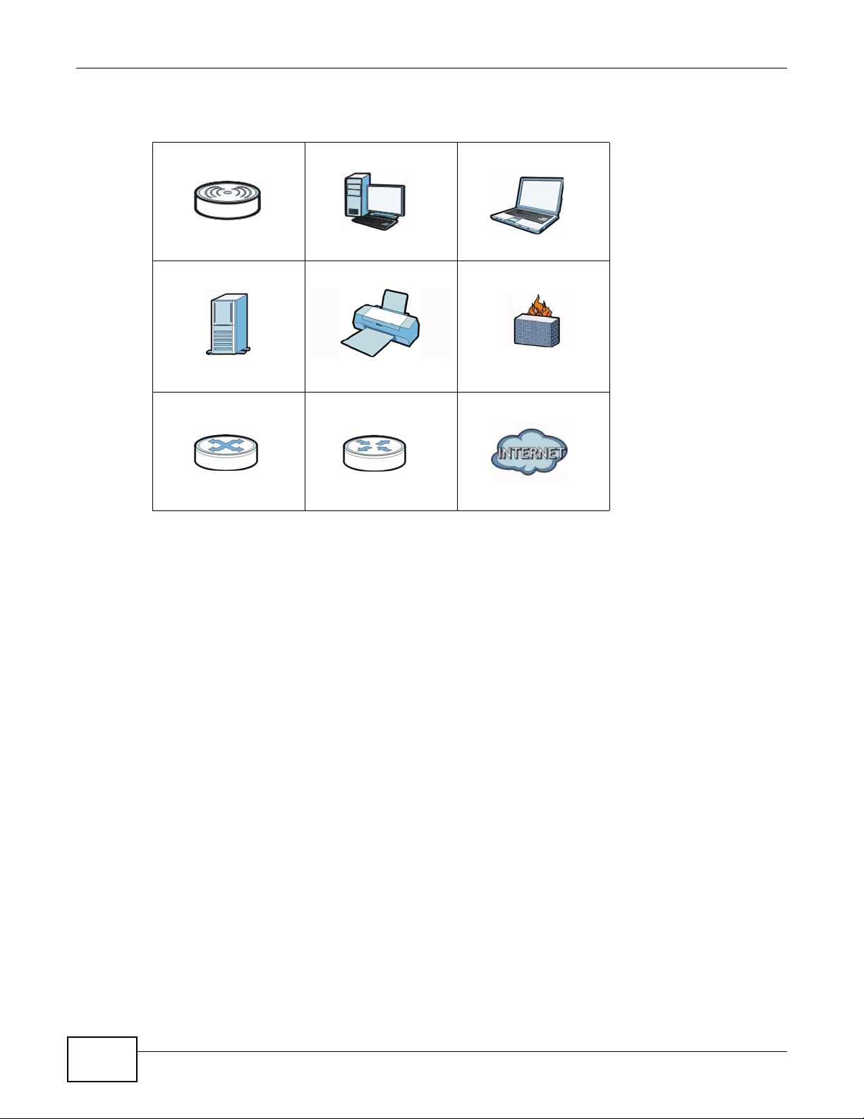
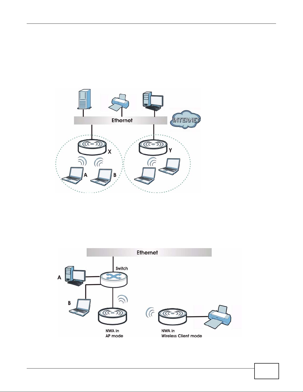
1.2.1 Access Point
The NWA is an ideal access solution for wireless Internet connection. A typical Internet access
application for your NWA is shown as follows. Stations A, B and C can access the wired network
through the NWAs.
Figure 1 Access Point Application
1.2.2 Bridge / Repeater
The NWA can act as a wireless network bridge and establish wireless links with other APs. In the
figure below, the two NWAs (A and B) are connected to independent wired networks and have a
bridge connection (A can communicate with B) at the same time. A NWA in repeater mode (C in
Figure 3) has no Ethernet connection. When the NWA is in bridge mode, you should enable
Spanning Tree Protocol (STP) to prevent bridge loops.
When the NWA is in Bridge / Repeater mode, security between APs (the Wireless Distribution
System or WDS) is independent of the security between the wireless stations and the AP. If you do
not enable WDS security , traffic between APs is not encrypted. When WDS security is enabled, both
APs must use the same pre-shared key. See Section 6.4.2 on page 65 for more details.
Once the security settings of peer sides match one another, the connection between devices is
made.
20
NWA1100-N User’s Guide
Page 21

Chapter 1 Introducing the NWA
At the time of writing, WDS security is compatible with other ZyXEL NWA-series access points only.
Refer to your other access point’s documentation for details.
Figure 2 Bridge Application
Figure 3 Repeater Application
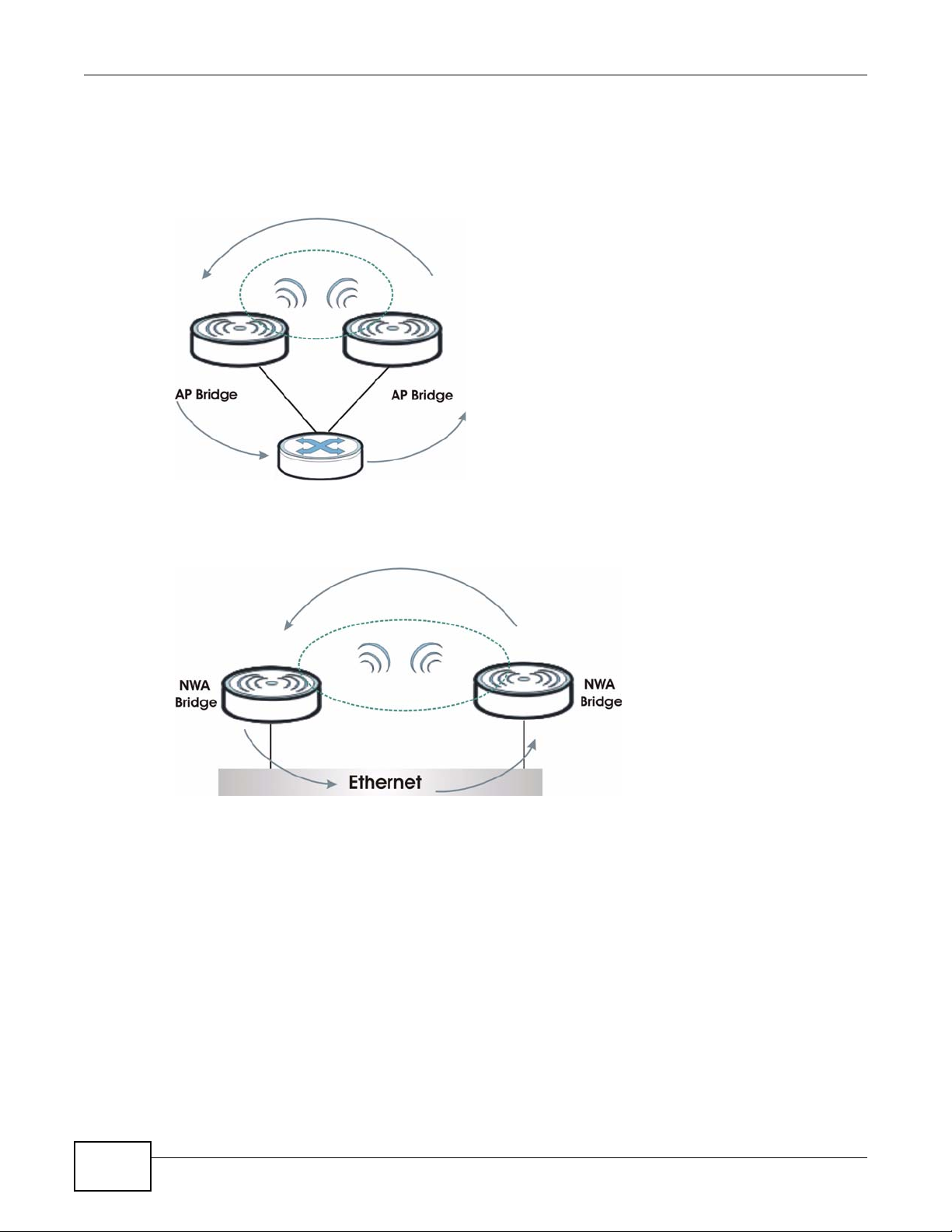
1.2.2.1 Bridge / Repeater Mode Example
In the example below, when both NWAs are in Bridge mode, they form a WDS (Wireless
Distribution System) allowing the computers in LAN 1 to connect to the computers in LAN 2.
Figure 4 Bridging Example
Be careful to avoid bridge loops when you enable bridging in the NWA. Bridge loops cause
broadcast traffic to circle the network endlessly, resulting in possible throughput degradation and
NWA1100-N User’s Guide
21
Page 22
Chapter 1 Introducing the NWA
disruption of communications. The following examples show two network topologies that can lead
to this problem:
• If two or more NWAs (in bridge mode) are connected to the same hub.
Figure 5 Bridge Loop: Two Bridges Connected to Hub
• If your NWA (in Bridge mode) is connected to a wired LAN while communicating with another
wireless bridge that is also connected to the same wired LAN.
Figure 6 Bridge Loop: Bridge Connected to Wired LAN
To prevent bridge loops, ensure that you enable STP in the Wireless screen or your NWA is not set
to bridge mode while connected to both wired and wireless segments of the same LAN.
1.2.3 AP + Bridge
In AP+Bridge mode, the NWA supports both AP and bridge connection at the same time.
In the figure below, A and B use X as an AP to access the wired network, while X and Y
communicate in bridge mode.
Using AP + Bridge mode, your NW A can extend the range of the WLAN. In the figure below , A and
B act as AP + Bridge devices that forward traffic between associated wireless workstations and the
wired LAN.
22
NWA1100-N User’s Guide
Page 23
Chapter 1 Introducing the NWA
When the NWA is in AP+Bridge mode, security between APs (the Wireless Distribution System or
WDS) is independent of the security between the wireless stations and the AP. If you do not enable
WDS security, traffic between APs is not encrypted. When WDS security is enabled, both APs must
use the same pre-shared key. See Section 6.4.3 on page 69 for more details.
Unless specified, the term “security settings” refers to the traffic between the wireless stations and
the NWA.
Figure 7 AP + Bridge Application
1.2.4 Wireless Client
The NWA can be used as a wireless client to communicate with an existing network. In the figure
below, the printer can receive requests from the wired computer clients A and B via the NWA in
Wireless Client mode.
Figure 8 Wireless Client Application
NWA1100-N User’s Guide
23
Page 24
Chapter 1 Introducing the NWA
1.2.5 MBSSID
A Basic Service Set (BSS) is the set of devices forming a single wireless network (usually an access
point and one or more wireless clients). The Service Set IDentifier (SSID) is the name of a BSS. In
Multiple BSS (MBSSID) mode, the NWA provides multiple virtual APs, each forming its own BS S and
using its own individual SSID profile.
You can configure up to eight SSID profiles, and have up to four active at any one time.
You can assign different wireless and security settings to each SSID profile. This allows you to
compartmentalize groups of users, set varying access privileges, and prioritize network traffic to
and from certain BSSs.
To the wireless clients in the network, each SSID appears to be a different access point. As in any
wireless network, clients can associate only with the SSIDs for which they have the correct security
settings.
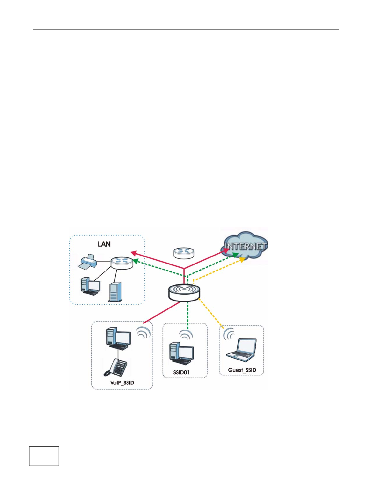
For example, you might want to set up a wireless network in your office where Internet telephony
(VoIP) users have priority. You also want a regular wireless network for standard users, as well as a
‘guest’ wireless network for visitors. In the following figure, VoIP_SSID users have QoS priority,
SSID01 is the wireless network for standard users, and Guest_SSID is the wireless network for
guest users. In this example, the guest user is forbidden access to the wired Land Area Network
(LAN) behind the AP and can access only the Internet.
Figure 9 Multiple BSSs
24
NWA1100-N User’s Guide
Page 25

Chapter 1 Introducing the NWA
1.3 Ways to Manage the NWA
Use any of the following methods to manage the NWA.
• Web Configurator. This is recommended for everyday management of the NWA using a
(supported) web browser.
• Command Line Interface. Line commands are mostly used for troubleshooting by service
engineers.
• FTP (File Transfer Protocol) for firmware upgrades.
• SNMP (Simple Network Management Protocol). The device can be monitored by an SNMP
manager.
1.4 Configuring Yo ur NWA’s Security Features
Your NWA comes with a variety of security features. This section summarizes these features and
provides links to sections in the User’s Guide to configure security settings on your NWA. Follow the
suggestions below to improve security on your NWA and network.
1.4.1 Control Access to Your Device
Ensure only people with permission can access your NWA.
• Control physical access by locating devices in secure areas, such as locked rooms. Most NWAs
have a reset button. If an unauthorized person has access to the reset button, they can then
reset the device’s password to its default password, log in and reconfigure its settings.
• Change any default passwords on the NWA, such as the password used for accessing the NWA’s
web configurator (if it has a web configurator). Use a password with a combination of letters and
numbers and change your password regularly. Write down the password and put it in a safe
place.
• Avoid setting a long timeout period before the NW A’ s web configurator automatically times out. A
short timeout reduces the risk of unauthorized person accessing the web configurator while it is
left idle.
•See Chapter 5 on page 55 for instructions on changing your password and setting the timeout
period.
• Configure remote management to control who can manage your NWA. See Chapter 12 on page
109 for more information. If you enable remote management, ensure you have enabled remote
management only on the IP addresses, services or interfaces you intended and that other remote
management settings are disabled.
1.4.2 Wireless Security
Wireless devices are especially vulnerable to attack. If your NWA has a wireless function, take the
following measures to improve wireless security.
• Enable wireless security on your NWA. Choose the most secure encryption method that all
devices on your network support. See Section 8.4 on page 87 for directions on configuring
encryption. If you have a RADIUS server, enable IEEE 802.1x or WPA(2) user identification on
your network so users must log in. This method is more common in business environments.
NWA1100-N User’s Guide
25
Page 26

Chapter 1 Introducing the NWA
• Hide your wireless network name (SSID). The SSID can be regularly broadcast and unauthorized
users may use this information to access your network. See Section 6.4 on page 62 for directions
on using the web configurator to hide the SSID.
• Enable the MAC filter to allow only trusted users to access your wireless network or deny
unwanted users access based on their MAC address. See Section 10.4 on page 103 for directions
on configuring the MAC filter.
1.5 Good Habits for Managing the NWA
Do the following things regularly to make the NWA more secure and to manage it more effectively.
1.6 Hardware Connections
See your Quick Start Guide for information on making hardware connections.
26
NWA1100-N User’s Guide
Page 27
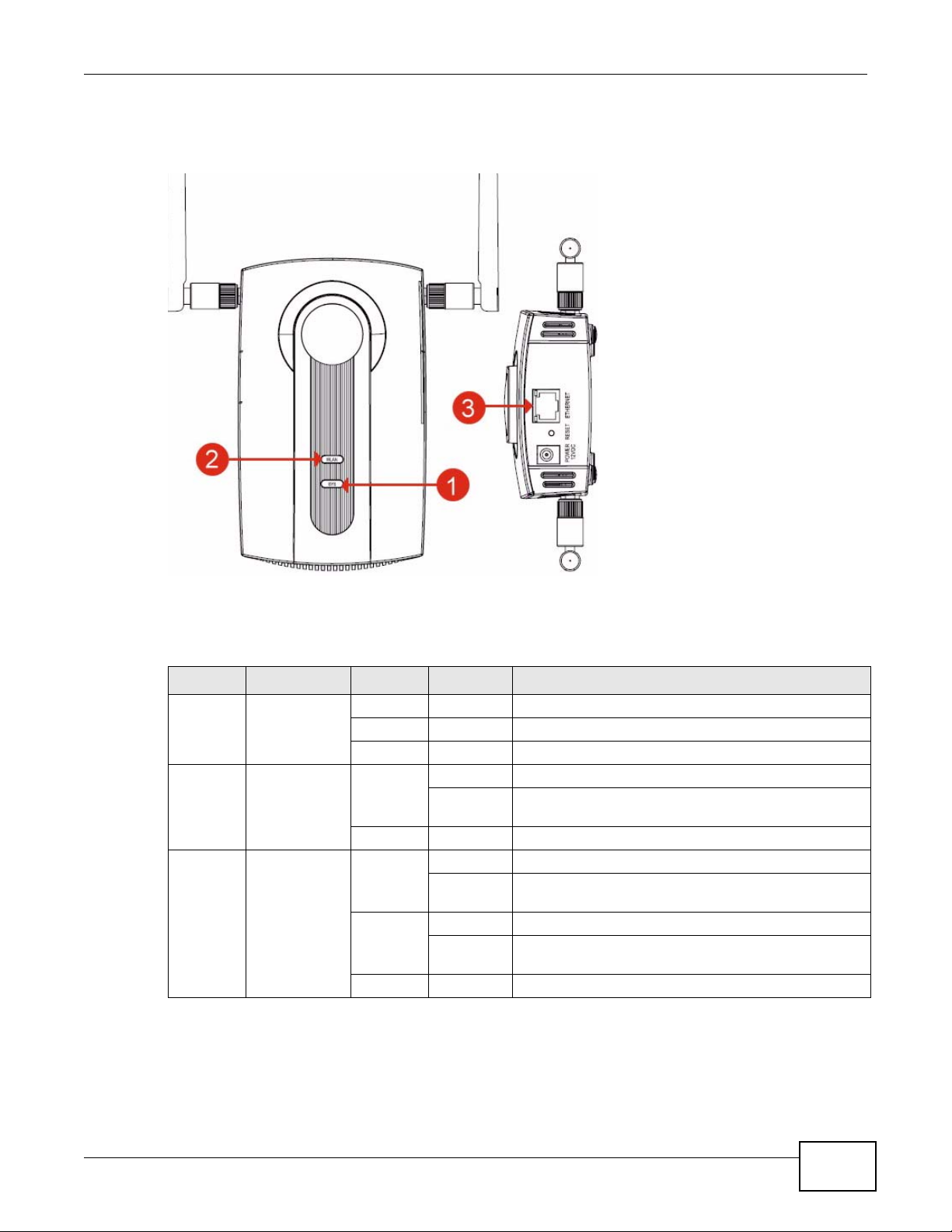
1.7 LEDs
Figure 10 LEDs
Chapter 1 Introducing the NWA
Ta ble 2 LEDs
LABEL LED COLOR STATUS DESCRIPTION
1 SYS Green On The NWA is receiving power and ready for use.
Red Flashing There is system error and the NWA cannot boot up.
Off The NWA is not receiving power.
2 WLAN Green On The wireless adaptor WLAN is active.
Blinking The wireless adaptor WLAN is active, and transmitting
Off The wireless adaptor WLAN is not active.
3 ETHERNET Green On The NWA has a 10/100 Mbps Ethernet connection.
Blinking The NWA has a 10/100 Mbps Ethernet connection and
Yellow On The NWA has a 1000 Mbps Ethernet connection.
Blinking The NWA has a 1000 Mbps Ethernet connection and is
Off The NWA does not have an Ethernet connection.
or receiving data.
is sending or receiving data.
sending/receiving data.
NWA1100-N User’s Guide
27
Page 28

Chapter 1 Introducing the NWA
28
NWA1100-N User’s Guide
Page 29
CHAPTER 2
Introducing the Web Configurator
This chapter describes how to access the NWA’s web configurator and provides an overview of its
screens.
2.1 Accessing the Web Configurator
1 Make sure your hardware is properly connected and prepare your computer or computer network to
connect to the NWA (refer to the Quick Start Guide).
2 Launch your web browser.
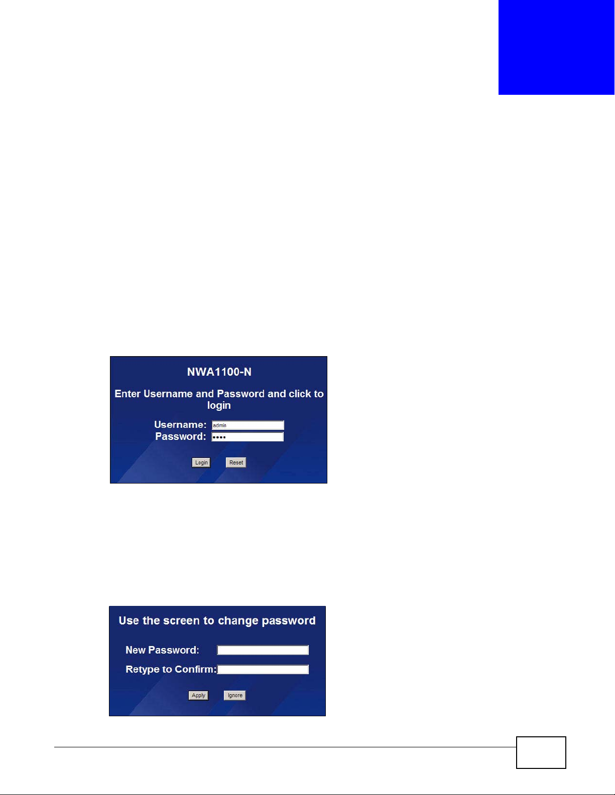
3 Type "192.168.1.2" as the URL (default). The login screen appears.
Figure 11 The Login Screen
4 Type “admin” as the (default) username and “1234” as the (default) password. Click Login.
5 You should see a screen asking you to change your password (highly recommended) as shown
next. Type a new password (and retype it to confirm) then click Apply . Alternatively, click Ignore.
Note: If you do not change the password, the following screen appears every time you
login.
Figure 12 Change Password Screen
NWA1100-N User’s Guide 29
Page 30
Chapter 2 Introducing the Web Configurator
You should now see the Status screen. See Chapter 2 on page 29 for details about the Status
screen.
Note: The management session automatically times out when the time period set in the
Administrator Inactivity Timer field expires (default five minutes). Simply log back
into the NWA if this happens.
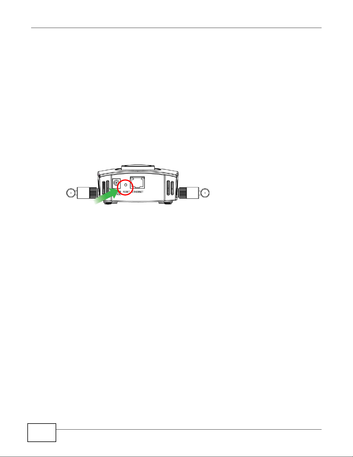
2.2 Resetting the NWA
If you forget your password or cannot access the web configurator, you will need to use the RESET
button at the rear panel of the NWA. This replaces the current configuration file with the factorydefault configuration file. This means that you will lose all the settings you previously configured.
The password will be reset to “1234”.
Figure 13 The RESET Button
2.2.1 Methods of Restoring Factory-Defaults
You can erase the current configuration and restore factory defaults in two ways:
Use the RESET button to upload the default configuration file. Hold this button in for about 10
seconds (the lights will begin to blink). Use this method for cases when the password or IP address
of the NWA is not known.
Use the web configurator to restore defaults (refer to Section 15.7 on page 133).
2.3 Navigating the Web Configurator
The following summarizes how to navigate the web configurator from the Status screen.
30
NWA1100-N User’s Guide
Page 31

Chapter 2 Introducing the Web Configurator
Check the status bar at the bottom of the screen when you click Apply or OK to verify that the
configuration has been updated.
Figure 14 Status Screen of the Web Configurator
• Click the links on the left of the screen to configure advanced features such as SYSTEM (General,
Password and Time), WIRELESS (Wireless Settings, SSID, Security, RADIUS, MAC Filter), IP,
REMOTE MGNT (Telnet, FTP, WWW and SNMP), CERTIFICATES, and LOGS (View Log and Log
Settings).
• Click MAINTENANCE to view information about your NWA or upgrade configuration a nd
firmware files. Maintenance features include Association List, Channel Usage, F/W
(firmware) Upload, Configuration File (Backup, Restore and Default) and Restart.
• Click LOGOUT at any time to exit the web configurator.
NWA1100-N User’s Guide
31
Page 32

Chapter 2 Introducing the Web Configurator
32
NWA1100-N User’s Guide
Page 33

The Status screens display when you log into the NWA, or click Status in the navigation menu.
Use the Status screens to look at the current status of the device, system resources, and
interfaces. The Status screens also provide detailed information about system statistics, associated
wireless clients, and logs.
3.1 The Status Screen
Use this screen to get a quick view of system, Ethernet, WLAN and other information regarding
your NWA.
Click Status. The following screen displays.
CHAPTER 3
Status Screens
Figure 15 The Status Screen
The following table describes the labels in this screen.
Ta ble 3 The Status Screen
LABEL DESCRIPTION
Automatic Refresh
Interval
Refresh Now Click this to update this screen immediately.
System Information
Select how often you want the NWA to update this screen.
NWA1100-N User’s Guide 33
Page 34

Chapter 3 Status Screens
Ta ble 3 The Status Screen (continued)
LABEL DESCRIPTION
Device Name This field displays the NWA system name. It is used for identification. You
WLAN Operation
Mode
Firmware Version This field displays the current version of the firmware inside the device . It
Current Date Time This field displays the date and time configured on the NWA. You can
Ethernet Information
LAN MAC Address This displays the MAC (Media Access Control) address of the NWA on the
IP Address This field displays the current IP address of the NWA on the network.
Subnet Mask Subnet masks determine the maximum number of possible hosts on a
Gateway IP Address This is the IP address of the gateway. The gateway is a router or switch
WLAN Information
SSID This field displays the SSID (Service Set Identifier). This is avai lable only
Channel The channel or frequency used by the NWA to send and receive
Status This shows the current status of the wireless LAN. This is available only
Security Mode This displays the security mode the NWA is using.
System Resources
System Up Time This field displays the elapsed time since the NWA was turned on.
CPU Usage This field displays what percentage of the NWA’s processing ability is
Memory Usage This field displays what percentage of the NWA’s volatile memory is
Interface Status
Interface This column displays each interface of the NWA.
Status This field indicates whether or not the NWA is using the interface.
Channel Click this to see which wireless channels are currently in use in the local
Rate For the LAN port this displays the port speed and duplex setting.
can change this in the System > General screen’s Device Name field.
This field displays the current operating mode of the first wireless module
(Access Point, Bridge/Repeater, AP+Bridge, Wireless Client, or
MBSSID). You can change the operating mode in the Wireless >
Wireless Settings screen.
also shows the date the firmware version was created. You can change
the firmware version by uploading new firmware in Maintenance > F/W
Upload.
change this in the System > Time Setting screen.
LAN. Every network device has a unique MAC address which identifies it
across the network.
network. You can also use subnet masks to divide one network into
multiple sub-networks.
on the same network segment as the device's LAN port. The gateway
helps forward packets to their destinations.
when the WLAN Operation Mode is Wireless Client.
information.
when the WLAN Operation Mode is Wireless Client.
currently being used. The higher the CPU usage, the more likely the NWA
is to slow down.
currently in use. The higher the memory usage, the more likely the NWA
is to slow down. Some memory is required just to start the NWA and to
run the web configurator.
For each interface, this field displays Up when the NWA is using the
interface and Down when the NWA is not using the interface.
area. See Section 15.5 on page 130.
For the WLAN interface, it displays the downstream and upstream
transmission rate or N/A if the interface is not in use.
34
NWA1100-N User’s Guide
Page 35

Ta ble 3 The Status Screen (continued)
LABEL DESCRIPTION
LAN This field displays the number of wireless clients currently associated to
the first wireless module. Each wireless module supports up to 32
concurrent associations.
WLAN This field displays the number of wireless clients currently associated to
the second wireless module. Each wireless module supports up to 32
concurrent associations.
System Status
Statistics Click this link to view port status and packet specific statistics. See
Section 3.1.1 on page 35.
Association List Click this to see a list of wireless clients currently associated to each of
the NWA’s wireless modules. See Section 15.4 on page 129.
View Log Click this to see a list of logs produced by the NWA. See Chapter 14 on
page 123.
3.1.1 System Statistics Screen
Use this screen to view read-only information, including 802.11 Mode, Channel ID, Retry Count and
FCS Error Count. Also provided is the "poll interval". The Poll Interval field is configurable. The
fields in this screen vary according to the current wireless mode of each WLAN adaptor.
Chapter 3 Status Screens
Click Status > Statistics. The following screen pops up.
Figure 16 System Status: Statistics
The following table describes the labels in this screen.
Ta ble 4 System Status: Show Statistics
LABEL DESCRIPTION
Description This is the wireless LAN adaptor.
802.11 Mode This field shows which 802.11 mode the NWA is using.
Channel ID Click this to see which wireless channels are currently in use in the local area.
See Section 15.5 on page 130.
RX PKT This is the number of received packets on this port.
TX PKT This is the number of transmitted packets on this port.
Retry Count This is the total number of retries for transmitted packets (TX).
FCS Error Count This is the ratio percentage showing the total number of checksum error of
received packets (RX) over total RX.
Poll Interval Enter the time interval for refreshi ng statistics.
Set Interval Click this button to apply the new poll interval you entered above.
Stop Click this button to stop refreshing statistics.
NWA1100-N User’s Guide
35
Page 36

Chapter 3 Status Screens
36
NWA1100-N User’s Guide
Page 37

CHAPTER 4
This chapter first provides an overview of how to configure the wireless LAN on your NW A, and then
gives step-by-step guidelines showing how to configure your NWA for some example scenarios.
4.1 How to Configure the Wireless LAN
This section illustrates how to choose which wireless operating mode to use on the NWA and how to
set up the wireless LAN in each wireless mode. See Section 4.1.3 on page 38 for links to more
information on each step.
4.1.1 Choosing the Wireless Mode
•Use Access Point operating mode if you want to allow wireless clients to access your wired
network, all using the same security and Quality of Service (QoS) settings. See Section 1.2.1 on
page 20 for details.
•Use Bridge / Repeater operating mode if you want to use the NWA to communicate with other
access points. See Section 1.2.2 on page 20 for details.
•Use AP + Bridge operating mode if you want to use the NWA as an access point (see above)
while also communicating with other access points. See Section 1.2.3 on page 22 for details.
•Use Wireless Client operating mode if you want to use the NWA to access a wireles s network.
See Section 1.2.4 on page 23 for details.
The NWA is a bridge when other APs access your wired Ethernet network through the NWA.
•Use MBSSID (Multiple Basic Service Set Identifier) operating mode if you want to use the NWA
as an access point with some groups of users having different security or QoS settings from other
groups of users. See Section 1.2.5 on page 24 for details.
Tutorial
4.1.2 Wireless LAN Configuration Overview
The following figure shows the steps you should take to configure the wireless settings according to
the operating mode you select. Use the Web Configurator to set up your NWA’s wireless network
NWA1100-N User’s Guide 37
Page 38

Chapter 4 Tutorial
(see your Quick Start Guide for information on setting up your NWA and accessing the Web
Configurator).
Select the WLAN Adaptor you want to configure.
Select Operation Mode.
Access Point
Select Wireless Mode,
SSID Profile, and
Channel.
Configure RADIUS
authentication (optional).
Configure MAC Filter
(optional).
Bridge / Repeater
Select Wireless Mode,
SSID Profile, and
Channel.
Configure RADIUS
authentication (optional).
AP + Bridge
Select Wireless Mode,
SSID Profile, and
Channel.
Configure RADIUS
authentication (optional).
Configure MAC Filter
(optional).
Check your settings and test.
Wireless Client
Select the AP you
want to connect to.
Configure Security
Settings.
MBSSID
Select Wireless Mode
and SSID Profile.
Configure the selected
SSID Profiles.
Configure Security
Settings.
Configure RADIUS
authentication (optional).
Configure MAC Filter
(optional).
4.1.3 Further Reading
Use these links to find more information on the steps:
•Selecting a WLAN Adaptor: see Section 6.4.1 on page 63.
• Choosing 802.11 Mode: see Section 6.4.1 on page 63.
• Choosing a wireless Channel ID: see Section 6.4.1 on page 63.
• Choosing a Security mode: see Section 8.4.1 on page 89.
• Configuring an external RADIUS server: see Section 9.4 on page 100.
•Configuring MAC Filtering: see Section 10.1 on page 102.
38
NWA1100-N User’s Guide
Page 39

4.2 How to Configure Multiple Wireless Networks
In this example, you have been using your NWA as an access point for your office network (See
your Quick Start Guide for information on how to set up your NWA in Access P oint mode). Now your
network is expanding and you want to make use of the MBSSID feature (see Section 8.2.4 on page
139) to provide multiple wireless networks. Each wireless network will cater to a different type of
user.
You want to make three wireless networks: one standard office wireless network with all the same
settings you already have, another wireless network with high priority QoS settings for Voice over
IP (VoIP) users, and a guest network that allows visitors to access only the Internet and the
network printer.
To do this, you will take the following steps:
1 Edit the SSID profiles.
2 Change the operating mode from Access Point to MBSSID and reactivate the standard network.
3 Configure different security modes for the networks.
Chapter 4 Tutorial
4 Configure a wireless network for standard office use.
5 Configure a wireless network for VoIP users.
6 Configure a wireless network for guests to your office.
The following figure shows the multiple networks you want to set up. Your NWA is marked Z, the
main network router is marked A, and your network printer is marked B.
B
A
Z
NWA1100-N User’s Guide
39
Page 40

Chapter 4 Tutorial
The standard network (SSID01) has access to all resources. The VoIP network (VoIP_SSID) has
access to all resources and a high QoS priority . The guest network (Guest_SSID) has access to the
Internet and the network printer only, and a low QoS priority.
To configure these settings, you need to know the Media Access Control (MAC) addresses of the
devices you want to allow users of the guest network to access. The following table shows the
addresses used in this example.
Ta ble 5 Tutorial: Example Information
Network router (A) MAC address 00:AA:00:AA:00:AA
Network printer (B) MAC address AA:00:AA:00:AA:00
4.2.1 Configure the SSID Profiles
1 Log in to the NWA (see Section 2.2 on page 35). Click Wireless > SSID. The SSID screen
appears.
2 Select the Profile1 check-box and click Edit.
3 Rename the Profile Name as SSID01. Click Save.
4 Repeat Step 2 and 3 to change Profile2 and Profile3 to VoIP_SSID and Guest_SSID.
40
NWA1100-N User’s Guide
Page 41

4.2.1.1 MBSSID
1 Go to Wireless > Wireless Settings. Select MBSSID from the Operating Mode drop-down list
box.
2 SSID01 is the standard network, so select SSID01 as the first profile. It is always active.
3 Select VoIP_SSID as the second profile, and Guest_SSID as the third profile. Select the
corresponding Active check-boxes.
4 Click Apply to save your settings. Now the three SSIDs are activated.
Chapter 4 Tutorial
NWA1100-N User’s Guide
41
Page 42

Chapter 4 Tutorial
4.2.2 Configure the Standard Network
1 Click Wireless > SSID. Select SSID01 and click Edit.
2 Select SecProfile1 as SSID01’s security profile. Select the Hidden SSID checkbox as you want
only authorized company employees to use this netw ork, so there is no need to broadcast the S SID
to wireless clients scanning the area.
Also, the clients on SSID01 might need to access other clients on the same wireless network. Do
not select the Enable Intra-BSS Traffic blocking check-box.
Click Save.
42
NWA1100-N User’s Guide
Page 43

Chapter 4 Tutorial
3 Next, click Wireless > Security. Select SecProfile1 and click Edit.
4 Since SSID01 is the standard network that has access to all resources, assign a more secure
security mode. Select WPA2-PSK-MIX as the Security Mode, and enter the Pre-Shared Key. In
this example, use ThisisSSID01PreSharedKey. Click Apply.
5 You have finished configuring the standard network, SSID01.
4.2.3 Configure the VoIP Network
1 Go to Wireless > SSID. Select VoIP_SSID and click Edit.
NWA1100-N User’s Guide
43
Page 44
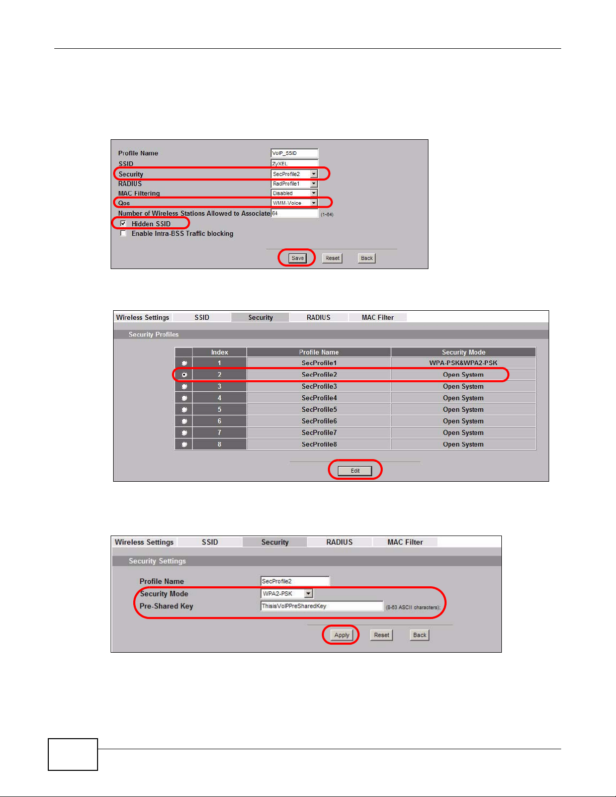
Chapter 4 Tutorial
2 Select SecProfile2 as the Security Profile for the VoIP network. Select the Hidden SSID check-
box.
3 Select WMM-Voice in the QoS field to give VoIP the highest priority in the wireless network. Click
Save.
4 Next, click Wireless > Security. Select SecProfile2 and click Edit.
5 Select WPA2-PSK as the Security Mode, and enter the Pre-Shared Key. In this example, use
ThisisVoIPPreSharedKey. Click Apply.
6 Your VoIP wireless network is now ready to use. Any traffic using the VoIP_SSID profile will be
given the highest priority across the wireless network.
44
NWA1100-N User’s Guide
Page 45

4.2.4 Configure the Guest Network
When you are setting up the wireless network for guests to your office, your primary concern is to
keep your network secure while allowing access to certain resources (such as a network printer, or
the Internet). For this reason, the pre-configured Guest_SSID profile has intra-BSS tr affic blocking
enabled by default. “Intra-BSS traffic blocking” means that the client cannot access other clients on
the same wireless network.
1 Click Wireless > SSID. Select Guest_SSID and click Edit.
Chapter 4 Tutorial
2 Select SecProfile3 in the Security field. Do not select the Hidden SSID check-box so the guests
can easily find the wireless network.
3 Select WMM-best effort in the QoS field to give the guest a lower QoS priority.
4 Select the check-box of Enable Intra-BSS Traffic blocking. Click Save.
NWA1100-N User’s Guide
45
Page 46

Chapter 4 Tutorial
5 Next, click Wireless > Security. Select SecProfile3 and click Edit.
6 Select WPA-PSK in the Security Mode field. WPA-PSK provide s strong security that is supported
by most wireless clients. Even though your Guest_SSID clients do not have access to sensitive
information on the network, you should not leave the network without security. An attacker could
still cause damage to the network or intercept unsecured communications or use your Internet
access for illegal activities.
7 Enter the PSK you want to use in your network in the Pre Shared Key field. In this example, the
PSK is ThisismyGuestWPApre-sharedkey. Click Apply.
8 Your guest wireless network is now ready to use.
4.2.5 Testing the Wireless Networks
To make sure that the three networks are correctly configured, do the following.
• On a computer with a wireless client, scan for access points. You should see the Guest_SSID
network, but not the SSID01 and VoIP_SSID networks. If you can see the SSID01 and
VoIP_SSID networks, go to its SSID Edit screen and make sure to select the Hidden SSID
check-box and click Save.
• Try to access each network using the correct security settings, and then using incorrect security
settings, such as the WPA-PSK for another active network. If the behavior is different from
expected (for example, if you can access the SSID01 or VoIP_SSID wireless network using the
security settings for the Guest_SSID wireless network) check that the SSID profile is set to use
the correct security profile, and that the settings of the security profile are correct.
46
NWA1100-N User’s Guide
Page 47

4.3 NWA Setup in AP and Wireless Client Modes
This example shows you how to restrict wireless access to your NWA.
4.3.1 Scenario
In the figure below, there are two NWAs (A and B) in the network. A is in Access Point (AP) mode
while station B is in Wireless Client mode. Station B is connected to a File Transfer Protocol (FTP)
server. You want only specified wireless clients to be able to access station B. Y ou also w ant to allow
wireless traffic between B and wireless clients connected to A (W, Y and Z). Other wireless devices
(X) must not be able to connect to the FTP server.
Figure 17 FTP Server Connected to a Wireless Client
Chapter 4 Tutorial
4.3.2 Configuring the NWA in Access Point Mode
Before setting up the NWA as a wireless client (B), you need to make sure there is an access point
to connect to. Use the Ethernet port on NWA (A) to configure it via a wired connection.
NWA1100-N User’s Guide
47
Page 48

Chapter 4 Tutorial
Log into the Web Configurator on NWA (A) and go to the Wireless > Wireless Settings screen.
1 Set the Operation Mode to Access Point.
2 Select the Wireless Mode. In this example, select 802.11b/g.
3 Select Profile1 as the SSID Profile.
4 Choose the Channel you want NWA (A) to use.
5 Click Apply.
48
NWA1100-N User’s Guide
Page 49

Chapter 4 Tutorial
6 Go to Wireless > SSID. Select Profile1 and click Edit.
7 Change the SSID to AP-A.
8 Select SecProfile1 in the Security field.
9 Select the check-box for Enable Intra-BSS Traffic blocking so the client cannot access other
clients on the same wireless network.
10 Click Save.
11 Go to Wireless > Security. Select SecProfile1. Click Edit.
NWA1100-N User’s Guide
49
Page 50

Chapter 4 Tutorial
12 Configure WPA-PSK as the Security Mode and enter ThisisMyPreSharedKey in the Pre-
Shared Key field.
13 Click Apply to finish configuration for NWA (A).
4.3.3 Configuring the NWA in Wireless Client Mode
The NWA (B) should have a wired connection before it ca n be set to wireless client oper ating mode.
Connect your NWA to the FTP server. Login to NWA (B)’ s Web Configurator and go to the Wireless
> Wireless Settings screen. Follow these steps to configure station B.
1 Select Wireless Client as Operation Mode. Click Apply.
2 Click on the Site Survey tab. A window should pop up which contains a list of all available wireless
devices within your NWA’s range.
50
NWA1100-N User’s Guide
Page 51

Chapter 4 Tutorial
3 Find and select NWA1100-N-A’s SSID: NWA-1100-A. Click Selected.
4 Go to Wireless > Security to configure the NWA to use the same security mode and Pre-Shared
Key as NWA1100-N-A: WPA-PSK/ThisisMyPreSharedKey. Click Apply.
Figure 18
4.3.4 MAC Filter Setup
One way to ensure that only specified wireless clients can access the FTP server is by enabling MAC
filtering on NWA (B) (See Chapter 10 on page 102 for more information on MAC Filter ).
1 Go to Wireless > MAC Filter. Select MacProfile1 and click Edit.
NWA1100-N User’s Guide
51
Page 52

Chapter 4 Tutorial
2 Select Allow Listed in the Access Control Mode field. Enter the MAC addresses of the wireless
clients (W, Y and Z) you want to associate with the NWA. Click Apply.
Now, only the authorized wireless clients (W, Y and Z) can access the FTP server.
4.3.5 Testing the Connection and Troubleshooting
This section discusses how you can check if you have correctly configured your network setup as
described in this tutorial.
• Try accessing the FTP server from wireless clients W, Y or Z. Test if you can send or retrieve a
file. If you cannot establish a connection with the FTP server, do the following steps.
1 Make sure W, Y and Z use the same wireless security settings as A and can access A.
2 Make sure B uses the same wireless and wireless security settings as A and can access A.
3 Make sure intra-BSS traffic is enabled on A.
• Try accessing the FTP server from X. If you are able to access the FTP server, do the following.
1 Make sure MAC filtering is enabled.
2 Make sure X’s MAC address is not entered in the list of allowed devices.
52
NWA1100-N User’s Guide
Page 53

PART II
Technical Reference
The appendices provide general information. Some details may not apply to your NWA.
53
Page 54

54
Page 55

5.1 Overview
This chapter provides information and instructions on how to identify and manage your NWA over
the network.
Figure 19 NWA Setup
CHAPTER 5
System Screens
In the figure above, the NWA connects to a Domain Name Server (DNS) server to avail of a domain
name. It also connects to an Network Time Protocol (NTP) server to set the time on the device.
5.2 What You Can Do in this Chapter
•Use the System > General screen to specify the System Name and Ethernet Data Rate value
(see Section 5.4 on page 57) .
•Use the System > Password screen to manage the password for your NWA (see Section 5.4.1
on page 57).
•Use the System > Time Setting screen to change your NWA’s time and date. This screen allows
you to configure the NWA’s time based on your local time zone (see Section 5.5 on page 58).
5.3 What You Need To Know
IP Address Assignment
Every computer on the Internet must have a unique IP address. If your networks are isolated from
the Internet, for instance, only between your two branch offices, you can assign any IP addresses
NWA1100-N User’s Guide 55
Page 56

Chapter 5 System Screens
to the hosts without problems. However, the Internet Assigned Numbers Authority (IANA) has
reserved the following three blocks of IP addresses specifically for private networks.
Ta ble 6 Private IP Address Ranges
10.0.0.0 - 10.255.255.255
172.16.0.0 - 172.31.255.255
192.168.0.0 - 192.168.255.255
You can obtain your IP address from the IANA, from an ISP or have it assigned by a private
network. If you belong to a small organization and your Internet access is through an ISP, the ISP
can provide you with the Internet addresses for your local networks. On the other hand, if you are
part of a much larger organization, you should consult your network administrator for the
appropriate IP addresses.
Note: Regardless of your particular situation, do not create an arbitrary IP address;
always follow the guidelines above. For more information on address assignment,
please refer to RFC 1597, Address Allocation for Private Internets and RFC 1466,
Guidelines for Management of IP Address Space.
IP Address and Subnet Mask
Similar to the way houses on a street share a common street name, computers on a LAN share one
common network number.
Where you obtain your network number depends on your particular situation. If the ISP or your
network administrator assigns you a block of registered IP addresses, follow their instructions in
selecting the IP addresses and the subnet mask.
If the ISP did not explicitly give you an IP network number, then most likely you have a single user
account and the ISP will assign you a dynamic IP address when the connection is established. The
Internet Assigned Number Authority (IANA) reserved this block of addresses specifically for private
use; please do not use any other number unless you are told otherwise. Let's say you select
192.168.1.0 as the network number; which covers 254 individual addresses, from 192.168.1.1 to
192.168.1.254 (zero and 255 are reserved). In other words, the first three numbers specify the
network number while the last number identifies an individual computer on that network.
Once you have decided on the network number, pick an IP address that is easy to remember, for
instance, 192.168.1.2, for your device, but make sure that no other device on your network is
using that IP address.
The subnet mask specifies the network number portion of an IP address. Your device will compute
the subnet mask automatically based on the IP address that you entered. Y ou don't need to change
the subnet mask computed by the device unless you are instructed to do otherwise.
56
NWA1100-N User’s Guide
Page 57

5.4 General Screen
Use the General screen to identify your NWA over the network. Click System > General. The
following screen displays.
Figure 20 System > General
The following table describes the labels in this screen.
Chapter 5 System Screens
Ta ble 7 System > General
LABEL DESCRIPTION
System Settings
System Name Type a descriptive name to identify the NWA in the Ethernet network.
Ethernet Data Rate
Ethernet Data Rate Select an Ethernet port speed and duplex mode from the drop-down list.
Apply Click Apply to save your changes.
Cancel Click Cancel to reload the previous configuration for this screen.
5.4.1 Password Screen
Use this screen to control access to your NWA by assigning a password to it. Click System >
Password. The following screen displays.
Figure 21 System > Password
This name can be up to 15 alphanumeric characters long. Spaces are not
allowed, but dashes "-" are accepted.
Select Auto if you would like to hav e th e system configure this automatically.
NWA1100-N User’s Guide
57
Page 58

Chapter 5 System Screens
The following table describes the labels in this screen.
Ta ble 8 System > Pass word
LABEL DESCRIPTIONS
Current Password Type in your existing system password.
New Password Type yo ur new s ystem pas sword (max 19 char acters). Note that as you type
Retype to Confirm Retype your new system password for confirmation.
Apply Click Apply to save your changes.
Reset Click Reset to reload the previous configuration for this screen.
5.5 Time Screen
Use this screen to change your NWA’s time and date, click System > Time. The following screen
displays.
Figure 22 System > Time
a password, the screen displays an asterisk (*) for each character you type.
58
The following table describes the labels in this screen.
Ta ble 9 System > Time
LABEL DESCRIPTION
Current Time and Date
Current Date This field displays the last updated date from the time server.
Current Time This field displays the time of your NWA.
Each time you reload this page, the NWA synchronizes the time with the
time server (if configured).
Time and Date Setup
Enable NTP client
update
NTP server Select an NTP server from the drop-list box.
Select this to have the NWA use the predefined list of Network Time
Protocol (NTP) servers.
NWA1100-N User’s Guide
Page 59

Ta ble 9 System > Time (continued)
LABEL DESCRIPTION
Manual IP Enter the IP address or URL of your time server. Check with your ISP/
network administrator if you are unsure of this information.
Time Zone Setup
Time Zone Choose the time zone of your location. This will set the time difference
between your time zone and Greenwich Mean Time (GMT).
Apply Click Apply to save your changes.
Refresh Click Refresh to reload the previous configuration for this screen.
5.6 Technical Reference
This section provides some technical information about the topics covered in this chapter.
5.6.1 Pre-defined NTP Time Servers List
When you turn on the NWA for the first time, the date and time start at 2000-01-01 00:00:00.
When you select Auto in the System > Time Setting screen, the NWA then attempts to
synchronize with one of the following pre-defined list of NTP time servers.
Chapter 5 System Screens
The NWA continues to use the following pre-defined list of NTP time servers if you do not specify a
time server or it cannot synchronize with the time server you specified.
Table 10 Default Time Servers
ntp1.cs.wisc.edu
ntp1.gbg.netnod.se
ntp2.cs.wisc.edu
tock.usno.navy.mil
ntp3.cs.wisc.edu
ntp.cs.strath.ac.uk
ntp1.sp.se
time1.stupi.se
tick.stdtime.gov.tw
tock.stdtime.gov.tw
time.stdtime.gov.tw
When the NWA uses the pre-defined list of NTP time servers, it randomly selects one server and
tries to synchronize with it. If the synchronization fails, then the NWA goes through the rest of the
list in order from the first one tried until either it is successful or all the pre-defined NTP time
servers have been tried.
NWA1100-N User’s Guide
59
Page 60

6.1 Overview
This chapter discusses the steps to configure the Wireless Settings screen on the NWA. It also
introduces the wireless LAN (WLAN) and some basic scenarios.
Figure 23 Wireless Mode
CHAPTER 6
Wireless Settings Screen
In the figure above, the NWA allows access to another bridge device (A) and a notebook computer
(B) upon verifying their settings and credentials. It denies access to other devices (C and D) with
configurations that do not match those specified in your NWA.
6.2 What You Can Do in this Chapter
Use the Wireless > Wireless Settings screen to configure the NWA’s operation mode (see
Section 6.4 on page 62).
NWA1100-N User’s Guide 60
Page 61

6.3 What You Need To Know
BSS
A Basic Service Set (BSS) exists when all communications between wireless clients or between a
wireless client and a wired network client go through one access point (AP). Intra-BSS traffic is
traffic between wireless clients in the BSS.
ESS
An Extended Service Set (ESS) consists of a series of overlapping BSSs, each containing an access
point, with each access point connected together by a wired network. This wired connection
between APs is called a Distribution System (DS).
Operating Mode
The NWA can run in four operating modes as follows:
• AP (Access Point). The NWA is wireless access point that allows wireless communication
to other devices in the network.
• Bridge/Repeater. The NWA acts as a wireless network bridge and establishes wireless
links with other APs. You need to know the MAC address of the peer device, which also
must be in bridge mode. The NWA can establish up to five wireless links with other APs.
• AP+Bridge. The NWA functions as a bridge and access point simultaneously.
• Wireless Client. The NWA acts as a wireless client to access a wireless network.
• MBSSID Mode. The Multiple Basic Service Set Identifier (MBSSID) mode allows you to use
one access point to provide several BSSs simultaneously.
Chapter 6 Wireless Settings Screen
Refer to Chapter 1 on page 19 for illustrations of these wireless applications.
SSID
The SSID (Service Set IDentifier) identifies the Service Set with which a wireless station is
associated. Wireless stations associating to the access point (AP) must have the same SSID.
Normally, the NWA acts like a beacon and regularly broadcasts the SSID in the area. You can hide
the SSID instead, in which case the NWA does not broadcast the SSID. In addition, you should
change the default SSID to something that is difficult to guess.
This type of security is fairly weak, however, because there are ways for unauthorized wireless
devices to get the SSID. In addition, unauthorized wireless devices can still see the information that
is sent in the wireless network.
Channel
A channel is the radio frequency(ies) used by IEEE 802.11a/b/g wireless devices. Channels
available depend on your geog raphical area. You may have a choice of channels (for your region) so
you should use a different channel than an adjacent AP (access point) to reduce interference.
NWA1100-N User’s Guide
61
Page 62

Chapter 6 Wireless Settings Screen
Wireless Mode
The IEEE 802.1x standard was designed to extend the features of IEEE 802.11 to support extended
authentication as well as providing additional accounting and control features. Your NWA can
support 802.11b/g and 802.11b/g/n.
MBSSID
Traditionally, you needed to use differe nt APs to configure different Basic Service Sets (BSSs). As
well as the cost of buying extra APs, there was also the possibility of channel interference. The
NWA’s MBS SID (Multiple Basic Service Set IDentifier) function allows you to use one access point to
provide several BSSs simultaneously. You can then assign varying levels of privilege to different
SSIDs.
Wireless stations can use different BSSIDs to associate with the same AP.
The following are some notes on multiple BSS.
• A maximum of four BSSs are allowed on one AP simultaneously.
• You must use different WEP keys for different BSSs. If two stations have different BSSIDs (they
are in different BSSs), but have the same WEP keys, they ma y hear each other’s communications
(but not communicate with each other).
• MBSSID should not replace but rather be used in conjunction with 802.1x security.
6.4 Wireless Settings Screen
Use this screen to choose the operating mode for your NWA. Click Wireless > Wireless Settings.
The screen varies depending upon the operating mode you select.
62
NWA1100-N User’s Guide
Page 63

6.4.1 Access Point Mode
Use this screen to use your NWA as an access point. Select Access Point as the Operation Mode.
The following screen displays.
Figure 24 Wireless > Wireless Settings: Access Point
Chapter 6 Wireless Settings Screen
The following table describes the general wireless LAN labels in this screen.
Table 11 Wireless > Wireless Settings: Access Point
LABEL DESCRIPTION
Basic Settings
Operation Mode Select Access Point from the drop-down list.
Wireless Mode Select 802.11b/g to allow both IEEE802.11b and IEEE802.11g compliant WLAN
NWA1100-N User’s Guide
devices to associate with the NWA. The transmission rate of your NWA might be
reduced.
Select 802.11b/g/n to allow IEEE802.11b, IEEE802.11g and IEEE802.11n
compliant WLAN devices to associate wit h the Device. The tr ansmission r ate of the
NWA might be reduced.
63
Page 64

Chapter 6 Wireless Settings Screen
Table 11 Wireless > Wireless Settings: Access Point (continued)
LABEL DESCRIPTION
SSID Profile The SSID (Service Set IDentifier) identifies the Service Set with which a wireless
station is associated. Wireless stations associating to the access point (AP) must
have the same SSID. Select an SSID Profile from the drop-down list box.
Note: If you are configuring the NWA from a computer connected to the wireless
Channel Select the operating frequency/channel depending on your particular region from
the drop-down list box.
Channel Width This field displays only when you select 802.11 b/g/n in the 802.11 Wireless
Mode field.
A standard 20MHz channel offers transfer speeds of up to 150Mbps whereas a
40MHz channel uses two standard channels and offers speeds of up to 300Mbps.
However, not all devices support 40MHz channels.
Select the channel bandwidth you want to use for your wireless network.
It is recommended that you select 20/40 (20/40 MHz). This allows the NWA to
adjust the channel bandwidth depending on network conditions.
LAN and you change the NWA’s SSID or security settings, you will lose your
wireless connection when you press Apply to confirm. You must then
change the wireless settings of your computer to match the NWA’s new
settings.
Select 20 MHz if you want to lessen radio interference with other wirel ess devices
in your neighborhood.
Advanced Settings
Beacon Interval When a wirelessly network device sends a beacon, it includes with it a beacon
interval. This specifies the time period before the device sends the beacon again.
The interval tells receiving devices on the network how long they can wait in
lowpower mode before waking up to handle the beacon. A high value helps save
current consumption of the access point.
DTIM Interval Delivery Traffic Indication Message (DTIM) is the time period after which
broadcast and multicast packets are transmitted to mobile clients in the Active
Power Management mode. A high DTIM value can cause clients to lose
connectivity with the network.
Output Power Set the output power of the NWA in this field. If there is a high density of APs in
an area, decrease the output power of the NWA to reduce interference with other
APs. Select one of the following Full (Full Power), 50%, 25%, 12.5% or Min
(Minimum). See the product speci fications for more information on your NWA’s
output power.
Preamble Type Select Dynamic to have the AP automatically use short preamble when wireless
RTS/CTS
Threshold
Fragmentation The threshold (number of bytes) for the fragmentation boundary for directed
adapters support it, otherwise the AP uses long preamble.
Select Long if you are unsure what preamble mode the wireless adapters support,
and to provide more reliable communications in busy wireless networks.
(Request To Send) The threshold (number of bytes) for enabling RTS/CTS
handshake. Data with its frame size larger than this value will perform the RTS/
CTS handshake. Setting this attribute to be larger than the maximum MSDU (MAC
service data unit) size turns off the RTS/CTS handshake. Setting this attribute to
its smallest value (1) turns on the RTS/CTS handshake.
messages. It is the maximum data fragment size that can be sent.
64
NWA1100-N User’s Guide
Page 65

Chapter 6 Wireless Settings Screen
Table 11 Wireless > Wireless Settings: Access Point (continued)
LABEL DESCRIPTION
Rates
Configuration
MCS Table The MCS Rate table is available only when 802.11 b/g/n is selected in the
Apply Click Apply to save your changes.
Cancel Click Cancel to begin configuring this screen afresh.
This section controls the data rates permitted for clients.
For each Rate, select an option from the Configuration list. The o ptions are:
• Basic (1~11 Mbps only): Clients can always connect to the access point at
this speed.
• Optional: Clients can connect to the access point at this speed, when
permitted to do so by the AP.
• Disable: Clients cannot connect to the access point at this speed.
802.11 Wireless Mode field.
IEEE 802.11n supports many different data rates which are called MCS rates. MCS
stands for Modulation and Coding Scheme. This is an 802.11n feature that
increases the wireless network performance in terms of throughput.
For each MCS Rate (0 -15), select either Enable (default) to have the NWA use the
data rate. Select Disable if you do not want the NWA to use the data rate.
6.4.2 Bridge / Repeater Mode
Use this screen to have the NWA act as a wireless network bridge and establish wireless links with
other APs. You need to know the MAC address of the peer device, which also must be in bridge
mode.
NWA1100-N User’s Guide
65
Page 66

Chapter 6 Wireless Settings Screen
Use this screen to use the NWA as a wireless bridge. Select Bridge/Repeater as the Operation
Mode.
Figure 25 Wireless > Wireless Settings: Bridge/Repeater
66
The following table describes the bridge labels in this screen.
Table 12 Wireless > Wirele ss Settings: Bridge/Repeater
LABEL DESCRIPTIONS
Basic Settings
Operation Mode Select Bridge/Repeater in this field.
Wireless Mode Select 802.11b/g to allow both IEEE802.11b and IEEE802.11g compliant
WLAN devices to associate with the NWA. The transmission rate of your NWA
might be reduced.
Select 802.11b/g/n to allow IEEE802.11b, IEEE802.11g and IEEE802.11n
compliant WLAN devices to associate with the NWA. The transmission rate of
the NWA might be reduced.
NWA1100-N User’s Guide
Page 67

Chapter 6 Wireless Settings Screen
Table 12 Wireless > Wirele ss Settings: Bridge/Repeater (continued)
LABEL DESCRIPTIONS
SSID Profile The SSID (Service Set IDentifier) identifies the Service Set with which a
wireless station is associated. Wireless stations associating to the access
point (AP) must have the same SSID. Select an SSID Profile from the dropdown list box.
Note: If you are configuring the NWA from a computer connected to the
wireless LAN and you change the NWA’s SSID or security settings, you
will lose your wireless connection when you press Apply to confirm.
You must then change the wireless settings of your computer to ma tch
the NWA’s new settings.
Channel Select the operating frequency/channel depending on your particular region
from the drop-down list box.
Channel Width This field displays only when you select 802.11 b/g/n in the 802.11
Wireless Mode field.
A standard 20MHz channel offers transfer speeds of up to 150Mbps whereas
a 40MHz channel uses two standard channels and offers speeds of up to
300Mbps. However, not all devices support 40MHz channels.
Select the channel bandwidth you want to use for your wireless network.
It is recommended that you select 20/40 (20/40 MHz). This allows the NWA
to adjust the channel bandwidth depending on network conditions.
Select 20 MHz if you want to lessen radio interference with other wireless
devices in your neighborhood.
WDS Settings
Local Mac Address
Remote MAC
Address 1 - 4
A Wireless Distribution System is a wireless connection between two or more
APs.
Note: WDS security is independent of the security settings between the NWA
and any wireless clients.
Local MAC Address is the MAC address of your NWA. You can specify up to
4 remote devices’ MAC addresses in this section.
Advanced Settings
Output Power Set the output power of the NWA in this field. If there is a high density of APs
in an area, decrease the output power of the NWA to reduce interference with
other APs. Select one of the following Full (Full Power), 50%, 25%, 12.5%
or Min (Minimum). See the product specifications for more information on
your NWA’s output power.
Preamble Type Select Dynamic to have the AP automatically use short preamble when
wireless adapters support it, otherwise the AP uses long preamble.
Select Long if you are unsure what preamble mode the wireless adapters
support, and to provide more reliable communications in busy wireless
networks.
RTS/CTS Threshold (Request To Send) The threshold (number of bytes) for enabling RTS/CTS
handshake. Data with its frame size larger than this value will perform the
RTS/CTS handshake. Setting this attribute to be larger than the maximum
MSDU (MAC service data unit) size turns off the RT S/CTS handshake. Setting
this attribute to its smallest value (1 ) turns on the RTS/CTS handshake.
Fragmentation The threshold (number of bytes) for the fragmentation boundary for directed
messages. It is the maximum data fragment size that can be sent.
NWA1100-N User’s Guide
67
Page 68

Chapter 6 Wireless Settings Screen
Table 12 Wireless > Wirele ss Settings: Bridge/Repeater (continued)
LABEL DESCRIPTIONS
Rates Configuration This section controls the data rates permitted for clients.
MCS Table The MCS Rate table is available only when 802.11 b/g/n is selected in the
Apply Click Apply to save your changes.
Cancel Click Cancel to begin configuring this screen afresh.
For each Rate, select an option from the Configuration list. The options
are:
• Basic (1~11 Mbps only): Clients can always connect to the access point
at this speed.
• Optional: Clients can connect to the access point at this speed, when
permitted to do so by the AP.
• Disable: Clients cannot connect to the access point at this speed.
802.11 Wireless Mode field.
IEEE 802.11n supports many different data rates which are c alled MCS rat es.
MCS stands for Modulation and Coding Scheme. This is an 802.11n feature
that increases the wireless network performance in terms of throughput.
For each MCS Rate (0-15), select either Enable (default) to have the NWA
use the data rate. Select Disable if you do not want the NWA to use the data
rate.
68
NWA1100-N User’s Guide
Page 69

6.4.3 AP + Bridge Mode
Use this screen to have the NWA function as a bridge and access point simultaneously. Select
AP+Bridge as the Operation Mode. The following screen displays.
Figure 26 Wireless > Wireless Settings: AP+Bridge
Chapter 6 Wireless Settings Screen
See the tables describing the fields in the Access Point and Bridge / Repeater operating modes
for descriptions of the fields in this screen.
NWA1100-N User’s Guide
69
Page 70

Chapter 6 Wireless Settings Screen
6.4.4 Wireless Client Mode
Use this screen to turn your NWA into a wireless client. Select Wireless Client as the Operation
Mode. The following screen displays.
Figure 27 Wireless > Wireless Settings: Wireless Client
The following table describes the general wireless LAN labels in this screen.
Table 13 Wireless > Wirele ss Settings: Wi reless Client
LABEL DESCRIPTION
Basic Settings
Operation Mode Select Wireless Client in this field.
Site Survey Click this to view a list of available wireless access points wi thin t he range. Select
the AP you want to use and click Selected.
Note: After selecting Wireless Client as the Operation Mode in the Basic
Settings section, you must click Apply to be able to select from the AP list.
Wireless Mode Select 802.11b/g to allow both IEEE802.11b and IEEE802.11g compliant WLAN
devices to associate with the NWA. The transmission rate of your NWA might be
reduced.
Select 802.11b/g/n to allow IEEE802.11b, IEEE802.11g and IEEE802.11n
compliant WLAN devices to associate with the NWA. The transmission rate of the
NWA might be reduced.
70
NWA1100-N User’s Guide
Page 71

Chapter 6 Wireless Settings Screen
Table 13 Wireless > Wirele ss Settings: Wi reless Client (continued)
LABEL DESCRIPTION
SSID Profile The SSID (Service Set IDentifier) identifies the Service Set with which a wireless
station is associated. Wireless stations associating to the access point (AP) must
have the same SSID.
In this field, select the SSID of the AP you want to use (click Site Survey button
for a list of available APs). Click Apply. Set the security configuration for this
operating mode in the Wireless > Security screen. Check the Status screen to
check if the settings you set show in the WLAN information.
Note: If you are configuring the NWA from a computer connected to the wireless
LAN and you change the NWA’s SSID or security settings, you will lose your
wireless connection when you press Apply to confirm. You must then
change the wireless settings of your computer to match the NWA’s new
settings.
Channel This shows the operating frequency/channel in use. This field is read-only when
you select Wireless Client as your operation mode.
Channel Width This field displays only when you select 802.11 b/g/n in the 802.11 Wireless
Mode field.
A standard 20MHz channel offers transfer speeds of up to 150Mbps whereas a
40MHz channel uses two standard channels and offers speeds of up to 300Mbps.
However, not all devices support 40MHz channels.
Select the channel bandwidth you want to use for your wireless network.
It is recommended that you select 20/40 (20/40 MHz). This allows the NWA to
adjust the channel bandwidth depending on network conditions.
Select 20 MHz if you want to lessen radio interference with other wirel ess devices
in your neighborhood.
Advanced Settings
MAC Clone Choose Manual to configure the NWA’s MAC address by cloning the MAC address
Output Power Set th e output power of the NWA in this field. If there is a high density of APs in
Preamble Type Select Dynamic to have the NWA automatically use short preamble when the
RTS/CTS
Threshold
Extension
channel
protection mode
from a computer on your LAN. Choose Auto to use the factory default MAC
address of your NWA.
an area, decrease the output power of the NWA to reduce interference with other
APs. Select one of the following Full (Full Power), 50%, 25%, 12.5% or Min
(Minimum). See the product speci fications for more information on your NWA’s
output power.
wireless network your NWA is connected to supports it, otherwise the NWA uses
long preamble.
Select Long preamble if you are unsure what preamble mode the wireless device
your NWA is connected to supports, and to provide more reli able communi cations
in busy wireless networks.
(Request To Send) The threshold (number of bytes) for enabling RTS/CTS
handshake. Data with its frame size larger than this value will perform the RTS/
CTS handshake. Setting this attribute to be larger than the maximum MSDU (MAC
service data unit) size turns off the RTS/CTS handshake. Setting this attribute to
its smallest value (1) turns on the RTS/CTS handshake.
You can use CTS to self or RTS-CTS protection mechanism to reduce conflicts
with other wireless networks or hidden wireless clients. The throughput of RTS-
CTS is much lower than CTS to self. Using this mode may decrease your wireless
performance.
NWA1100-N User’s Guide
71
Page 72

Chapter 6 Wireless Settings Screen
Table 13 Wireless > Wirele ss Settings: Wi reless Client (continued)
LABEL DESCRIPTION
A-MPDU
aggregation
Short GI This field is available only when 802.11 b/g/n is selected as the Wireless
Apply Click Apply to save your changes.
Cancel Click Cancel to begin configuring this screen afresh.
This field is available only when 802.11 b/g/n is selected as the Wireless
Mode. Select Enable to allow the grouping of several A-MSDUs (Aggregate MAC
Service Data Units) into one large A-MPDU (Aggregate MAC Protocol Data Unit).
This function allows faster data transfer rates.
Mode. Select Enable to use Short GI (Guard Interval). The guard interval is the
gap introduced between data transmission from users in order to reduce
interference. Reducing the GI increases data transfer rates but also increases
interference. Increasing the GI reduces data transfer rates but also reduces
interference.
72
NWA1100-N User’s Guide
Page 73

6.4.5 MBSSID Mode
Use this screen to have the NWA function in MBSSID mode. Select MBSSID as the Operating
Mode. The following screen diplays.
Figure 28 Wireless > Wireless Settings: MBSSID
Chapter 6 Wireless Settings Screen
The following table describes the labels in this screen.
Table 14 Wireless > Wirele ss Settings: MBSSID
LABEL DESCRIPTION
Operating Mode Select MBSSID in this field.
802.11 Mode Select 802.11b/g to allow both IEEE802.11b and IEEE802.11g compliant
Channel Select the operating frequency/channel depending on your particular region
NWA1100-N User’s Guide
WLAN devices to associate with the NWA. The transmission rate of your
NWA might be reduced.
Select 802.11b/g/n to allow IEEE802.11b, IEEE802.11g and IEEE802.11n
compliant WLAN devices to associate with the NW A. The transmi ssion rate of
the NWA might be reduced.
from the drop-down list box.
73
Page 74

Chapter 6 Wireless Settings Screen
Table 14 Wireless > Wirele ss Settings: MBSSID (continued)
LABEL DESCRIPTION
Channel Width This field displays only when you sele ct 802.11 b/g/n in the 802.11
Select SSID Profile An SSID profile is the set of parameters relating to one of the NWA’s BSSs.
Index Select the check box to activate an SSID profile.
Active Select the check box to enable the bridge connection. Otherwise, clear the
Profile Select the profile(s) of the SSIDs you want to use in your wireless network.
Advanced Settings
Beacon Interval When a wirelessly networked device sends a beacon, it includes with it a
DTIM Interval Delivery Traffic Indication Message (DTIM) is the time period after which
Output Power Set the output power of the NWA in this field. If there is a high density of
Preamble Type Select Dynamic to have the AP automatically use short preamble when
Wireless Mode field.
A standard 20MHz channel offers transfer speeds of up to 150Mbps whereas
a 40MHz channel uses two standard channels and offers speeds of up to
300Mbps. However, not all devices support 40MHz channels.
Select the channel bandwidth you want to use for your wireless network.
It is recommended that you select 20/40 (20/40 MHz). This allows the NWA
to adjust the channel bandwidth depending on network conditions.
Select 20 MHz if you want to lessen radio interference with other wireless
devices in your neighborhood.
The SSID (Service Set IDentifier) identifies the Service Set with which a
wireless station is associated. Wireless stations associating with the access
point (AP) must have the same SSID.
If you are configuring the NWA from a computer connected to the wireless
LAN and you change the NWA’s SSID or security settings, you will lose your
wireless connection when you press Apply to confirm. You must then change
the wireless settings of your computer to match the NWA’s new settings.
check box to disable it. The first profile is always active.
You can have up to four BSSs running on the NWA simultaneously.
Configure SSID profiles in the SSID screen.
beacon interval. This specifies the time period before the device sends the
beacon again. The interval tells receiving devices on the network how long
they can wait in lowpower mode before waking up to handle the beacon. A
high value helps save current consumption of the access point.
broadcast and multicast packets are transmitted to mobile clients in the
Active Power Management mode. A high DTIM value can cause clients to
lose connectivity with the network.
APs in an area, decrease the output power of the NWA to reduce
interference with other APs. Select one of the following Full (Full Power),
50%, 25%, 12.5% or Min (Minimum). See the product specifications for
more information on your NWA’s output power.
wireless adapters support it, otherwise the AP uses long preamble.
74
Select Long if you are unsure what preamble mode the wireless adapters
support, and to provide more reliable communications in busy wireless
networks.
RTS/CTS Threshold (Request To Send) The threshold (number of bytes) for enabling RTS/CTS
handshake. Data with its frame size larger than this value will perform the
RTS/CTS handshake. Setting this attribute to be larger than the maximum
MSDU (MAC service data unit) size turns off the RTS/CTS handshake.
Setting this attribute to its smallest value (1) turns on the RTS/CTS
handshake.
NWA1100-N User’s Guide
Page 75

Chapter 6 Wireless Settings Screen
Table 14 Wireless > Wirele ss Settings: MBSSID (continued)
LABEL DESCRIPTION
Extension channel
protection mode
A-MPDU aggregation This field is available only when 802.11 b/g/n is selected as the Wireless
Short GI This field is available only when 802.11 b/g/n is selected as the Wireless
Rates Configuration This section controls the data rates permitted for clients.
MCS Table The MCS Rate table is av ailable only when 802.11 b/g/n is selected in the
You can use CTS to self or RTS-CTS protection mechanism to reduce
conflicts with other wireless networks or hidden wireless clients. The
throughput of RTS-CTS is much lower than CTS to self. Using this mode
may decrease your wireless performance.
Mode. Select Enable to allow the grouping of several A-MSDUs (Aggregate
MAC Service Data Units) into one large A-MPDU (Aggregate MAC Protocol
Data Unit). This function allows faster data transfer rates.
Mode. Select Enable to use Short GI (Guard Interval). The guard interval
is the gap introduced between data transmission from users in order to
reduce interference. Reducing the GI increases data transfer rates but also
increases interference. Increasing the GI reduces data transfer rates but
also reduces interference.
For each Rate, select an option from the Configuration list. The options
are:
• Basic (1~11 Mbps only): Clients can always connect to the access point
at this speed.
• Optional: Clients can connect to the access point at this speed, when
permitted to do so by the AP.
• Disable: Clients cannot connect to the access point at this speed.
802.11 Wireless Mode field.
IEEE 802.11n supports many different data rates which are called MCS
rates. MCS stands for Modulation and Coding Scheme. This is an 802.11n
feature that increases the wireless network performance in terms of
throughput.
For each MCS Rate (0-15), select either Enable (default) to have the NWA
use the data rate. Select Disable if you do not want the NWA to use the
data rate.
Apply Click Apply to save your changes.
Cancel Click Cancel to begin configuring this screen afresh.
6.5 Technical Reference
This section provides technical background information about the topics covered in this chapter.
Refer to Appendix E on page 191 for further readings on Wireless LAN.
6.5.1 WMM QoS
WMM (Wi-Fi MultiMedia) QoS (Quality of Service) ensures quality of service in wireless networks. It
controls WLAN transmission priority on packets to be transmitted over the wireless network.
WMM QoS prioritizes wireless traffic according to the delivery requirements of the individual and
applications. WMM QoS is a part of the IEEE 802.11e QoS enhancement to certified Wi-Fi wireless
networks.
NWA1100-N User’s Guide
75
Page 76

Chapter 6 Wireless Settings Screen
On APs without WMM QoS, all traffic streams are given the same access priority to the wireless
network. If the introduction of another traffic stream creates a data transmission demand that
exceeds the current network capacity, then the new traffic stream reduces the throughput of the
other traffic streams.
The NWA uses WMM QoS to prioritize traffic streams according to the IEEE 802.1q or DSCP
information in each packet’s header. The NWA automatically determines the priority to use for an
individual traffic stream. This prevents reductions in data transmission for applications that are
sensitive to latency and jitter (variations in delay).
6.5.2 Spanning Tree Protocol (STP)
STP detects and breaks network loops and provides backup links between switches, bridges or
routers. It allows a bridge to interact with other STP-compliant bridges in your network to ensure
that only one route exists between any two stations on the network.
6.5.2.1 Rapid STP
The NWA uses IEEE 802.1w RSTP (Rapid Spanning Tree Protocol) that allow faster convergence of
the spanning tree (while also being backwards compatible with STP-only aware bridges). Using
RSTP topology change information does not have to propagate to the root bridge and unwanted
learned addresses are flushed from the filtering database. In RSTP, the port states are Discarding,
Learning, and Forwarding.
6.5.2.2 STP Terminology
The root bridge is the base of the spanning tree; it is the bridge with the lowest identifier value
(MAC address).
Path cost is the cost of transmitting a frame onto a LAN through that port. It is assigned according
to the speed of the link to which a port is attached. The slower the media, the higher the cost - see
the following table.
Table 15 STP Path Costs
Path Cost 4Mbps 250 100 to 1000 1 to 65535
Path Cost 10Mbps 100 50 to 600 1 to 65535
Path Cost 16Mbps 62 40 to 400 1 to 65535
Path Cost 100Mbps 19 10 to 60 1 to 65535
Path Cost 1Gbps 4 3 to 10 1 to 65535
Path Cost 10Gbps 2 1 to 5 1 to 65535
On each bridge, the root port is the port through which this bridge communicates with the root. It is
the port on this switch with the lowest path cost to the root (the root path cost). If there is no root
port, then this bridge has been accepted as the root bridge of the spanning tree network.
For each LAN segment, a designated bridge is selected. This bridge has the lowest cost to the root
among the bridges connected to the LAN.
LINK SPEED
RECOMMENDED
VALUE
RECOMMENDED
RANGE
ALLOWED
RANGE
76
NWA1100-N User’s Guide
Page 77

6.5.2.3 How STP Works
After a bridge determines the lowest cost-spanning tree with STP, it enables the root port and the
ports that are the designated ports for connected LANs, and disables all other ports that participate
in STP. Network packets are therefore only forwarded between enabled ports, eliminating any
possible network loops.
STP-aware bridges exchange Bridge Protocol Data Units (BPDUs) periodically. When the bridged
LAN topology changes, a new spanning tree is constructed.
Once a stable network topology has been established, all bridges listen for Hello BPDUs (Bridge
Protocol Data Units) transmitted from the root bridge. If a bridge does not get a Hello BPDU after a
predefined interval (Max Age), the bridge assumes that the link to the root bridge is down. This
bridge then initiates negotiations with other bridges to reconfigure the network to re-establish a
valid network topology.
6.5.2.4 STP Port States
STP assigns five port states (see next table) to eliminate packet looping. A bridge port is not
allowed to go directly from blocking state to forwarding state so as to eliminate transient loops.
Table 16 STP Port States
PORT STATES DESCRIPTIONS
Disabled STP is disabled (default).
Blocking Only configuration and management BPDUs are received and processed.
Listening All BPDUs are received and processed.
Learning All BPDUs are received and processed. Information frames are submitted to the
Forwarding All BPDUs are received and processed. All information frames are received and
Chapter 6 Wireless Settings Screen
learning process but not forwarded.
forwarded.
6.5.3 Additional Wireless Terms
Table 17 Additional Wireless Terms
TERM DESCRIPTION
Intra-BSS Traffic This describes direct communication (not through the NWA) between two
wireless devices within a wireless network. You might disable this kind of
communication to enhance security within your wireless network.
RTS/CTS Threshold In a wireless network which covers a large area, wireless devices are
sometimes not aware of each other’s presence. This may cause th em to
send information to the AP at the same time and result in information
colliding and not getting through.
By setting this value lower than th e default v alue, the wireless devices must
sometimes get permission to send information to the NWA. The lower the
value, the more often the devices must get permission.
If this value is greater than the fragmentation threshold value (see below),
then wireless devices never have to get permission to send information to
the NWA.
Preamble A preamble affects the timing in your wireless netw ork. There are two
preamble modes: long and short. If a device uses a different preamble
mode than the NWA does, it cannot communicate with the NWA.
NWA1100-N User’s Guide
77
Page 78

Chapter 6 Wireless Settings Screen
TERM DESCRIPTION
Fragmentation
Threshold
Roaming If you have two or more NWAs (or other wireless access points) on your
Antenna An antenna couples Radio Frequency (RF) signals onto air. A transmitter
A small fragmentation threshold is recommended for busy networks, while a
larger threshold provides faster performance if the network is not very busy .
wireless network, you can enable this option so that wireless devices can
change locations without having to log in again. This is useful for devices,
such as notebooks, that move around a lot.
within a wireless device sends an RF signal to the antenna, which
propagates the signal through the air. The antenna also operates in reverse
by capturing RF signals from the air.
Positioning the antennas properly increases the range and coverage area of
a wireless LAN.
78
NWA1100-N User’s Guide
Page 79

7.1 Overview
This chapter describes how you can configure Service Set Identifier (SSID) profiles in your NWA.
Figure 29 Sample SSID Profiles
CHAPTER 7
SSID Screen
In the figure above, the NWA has three SSID profiles configured: a standard profile (SSID01), a
profile with high QoS settings for Voice over IP (VoIP) users (VoIP_SSID), and a guest profile that
allows visitors access only the Internet and the network printer (Guest_SSID).
7.1.1 What You Can Do in this Chapter
Use the Wireless > SSID screen to configure up to 16 SSID profiles for your NWA (see Section 7.2
on page 80).
7.1.2 What You Need To Know
The following terms and concepts may help as you read through this chapter.
When the NWA is set to Access Point, AP + Bridge or MBSSID mode, you need to choose the SSID
profile(s) you want to use in your wireless network (see Section 6.4 on page 62 for more
information on operating modes).
NWA1100-N User’s Guide 79
Page 80

Chapter 7 SSID Screen
To configure the settings of your SSID profile, you need to know the Media Access Control (MAC)
addresses of the devices you want to allow access to it.
Each SSID profile references the settings configured in the following screens:
• Wireless > Security (one of the security profiles)
• Wireless > RADIUS (one of the RADIUS profiles)
• Wireless > MAC Filter (the MAC filter list, if activated in the SSID profile)
• Also, use the VLAN screen to set up wireless VLANs based on SSID
Configure the fields in the above screens to use the settings in an SSID profile.
7.2 The SSID Screen
Use this screen to select the SSID profile you want to configure. Click Wireless > SSID to display
the screen as shown.
Figure 30 Wireless > SSID
80
The following table describes the labels in this screen.
Figure 31 Wireless > SSID
LABEL DESCRIPTION
Profile Settings
Index This field displays the index number of each SSID profile.
NWA1100-N User’s Guide
Page 81

Chapter 7 SSID Screen
Figure 31 Wireless > SSID (continued)
LABEL DESCRIPTION
Profile Name This field displays the identification name of each SSID profile on the NWA.
SSID This field displays the name of the wireless profile on the netw ork. When a
wireless client scans for an AP to associate with, this is the name that is
broadcast and seen in the wireless client utility.
Security This field indicates which security profile is currently associated with each
RADIUS This field displays which RADIUS profile is currently associated with each
QoS This field displays the Quality of Service setting for this profile or NONE if
MAC Filter This field displays which MAC filter profile is currently associated with each
Edit Click the radio button next to the profile you want to configure and click Edit
VLAN (802.1Q)
Enable 802.1Q VLAN Select this to enable VLAN tagging.
Management VLAN ID Enter a number from 1 to 4094 to define this VLAN group. At least one
BSSID1~4 VLAN ID Enter a VLAN ID number from 1 to 4094. Packets coming from the WLAN
Save Click Save to save your changes.
Reset Click Reset to begin configuring this screen afresh.
SSID profile. See Section 8.4.1 on page 89 for more information.
SSID profile, if you have a RADIUS server configured.
QoS is not configured on a profile.
SSID profile, or Disable if MAC filtering is not configured on an SSID profile.
to go to the SSID configuration screen.
device in your network must belong to this VLAN group in order to manage
the NWA.
using this BSSID profile are tagged with the VLAN ID number by the NWA.
Different BSSID profiles can use the same or different VLAN IDs. This allows
you to split wireless stations into groups using similar VLAN IDs.
7.2.1 Configuring SSID
Use this screen to configure an SSID profile. In the Wireless > SSID screen, select an SSID profile
and click Edit to display the following screen.
Figure 32 SSID: Edit
NWA1100-N User’s Guide
81
Page 82

Chapter 7 SSID Screen
The following table describes the labels in this screen.
Table 18 SSID: Edit
LABEL DESCRIPTION
Profile Name This is the name that identifying this profile.
SSID When a wireless client scans for an AP to associate with, this is the name
Security Select a security profile to use with this SSID profile. See Section 8.4.1 on
RADIUS Select a RADIUS profile from the drop-down list box, if you have a RADIUS
MAC Filtering
QoS Select the Quality of Service priority for this BSS’s traffic.
that is broadcast and seen in the wireless client utility.
page 89 for more information.
server configured. If you do not need to use RADIUS authentication, ignore
this field. See Section 9.4 on page 100 for more information.
Select a MAC filter profile from the drop-down list box. If you do not want to
use MAC filtering on this profile, select Disable.
•If you select WMM from the QoS list, the priority of a data packet
depends on the packet’s IEEE 802.1q or DSCP header. If a packet has no
WMM value assigned to it, it is assigned the default priority.
•If you select WMM_VOICE, WMM_VIDEO, WMM_BEST_EFFORT or
WMM_BACKGROUND, the NWA applies that QoS setting to all of that
SSID’s traffic.
•If you select NONE, the NWA applies no priority to traffic on this SSID.
Note: When you configure an SSID profile’s QoS settings, the NWA applies
the same QoS setting to all of the profile’s traffic.
Number of Wireless
Stations Allowed to
Associate
Hidden SSID If you do not select the checkbox, the NWA to broadcast this SSID (a
Enable Intra-BSS
Traffic blocking
Save Click Save to save your changes.
Reset Click Reset to begin configuring this screen afresh.
Back Click Back to return to the previous screen.
Use this field to set a maximum number of wireless stations that may
connect to the device.
wireless client scanning for an AP will find this SSID). Alternatively, if you
select the checkbox, the NWA hide this SSID (a wireless client scanning for
an AP will not find this SSID).
Select the checkbox to prevent wireless clients in this profile’s BSS from
communicating with one another.
7.3 Technical Reference
This section provides technical background information about the topics covered in this chapter.
7.3.1 WMM QoS
82
WMM (Wi-Fi MultiMedia) QoS (Quality of Service) ensures quality of service in wireless networks. It
controls WLAN transmission priority on packets to be transmitted over the wireless network.
WMM QoS prioritizes wireless traffic according to the delivery requirements of the individual and
applications. WMM QoS is a part of the IEEE 802.11e QoS enhancement to certified Wi-Fi wireless
networks.
NWA1100-N User’s Guide
Page 83

On APs without WMM QoS, all traffic streams are given the same access priority to the wireless
network. If the introduction of another traffic stream creates a data transmission demand that
exceeds the current network capacity, then the new traffic stream reduces the throughput of the
other traffic streams.
The NWA uses WMM QoS to prioritize traffic streams according to the IEEE 802.1q or DSCP
information in each packet’s header. The NWA automatically determines the priority to use for an
individual traffic stream. This prevents reductions in data transmission for applications that are
sensitive to latency and jitter (variations in delay).
7.3.1.1 WMM QoS Priorities
The following table describes the WMM QoS priority levels that the NWA uses.
Table 19 WMM QoS Priorities
Priority Level description
voice
(WMM_VOICE)
video
(WMM_VIDEO)
best effort
(WMM_BEST_EFFORT)
background
(WMM_BACKGROUND)
Chapter 7 SSID Screen
Typically used for traffic that is especially sensitive to jitter. Use this
priority to reduce latency for improved voice quality.
Typically used for traffic which has some tolerance for jitter but needs to
be prioritized over other data traffic.
Typically used for traffic from applications or devices that lack QoS
capabilities. Use best effort priority for traffic that is less sensitive to
latency, but is affected by long delays, such as Internet surfing.
This is typically used for non-critical traffic such as bulk transfers and
print jobs that are allowed but that should not affect other applications
and users. Use background priority for applications that do not have strict
latency and throughput requirements.
7.3.2 Type Of Service (ToS)
Network traffic can be classified by setting the ToS (Type Of Service) v alues at the data source (for
example, at the NWA) so a server can decide the best method of delivery, that is the least cost,
fastest route and so on.
7.3.2.1 ToS (Type of Service) and WMM QoS
The DSCP value of outgoing packets is between 0 and 255. 0 is the default priority. WM M QoS
checks the DSCP value in the header of data packets. It gives the traffic a priority according to this
number.
In order to control which priority level is given to traffic, the device sending the traffic must set the
DSCP value in the header. If the DSCP value is not specified, then the traffic is treated as besteffort. This means the wireless clients and the devices with which they are communicating must
both set the DSCP value in order to make the best use of WMM QoS. A Voice over IP (VoIP) device
for example may allow you to define the DSCP value.
The following table lists which WMM QoS priority level the NWA uses for specific DSCP values.
Table 20 ToS and IEEE 802.1d to WMM QoS Priority Level Mapping
Dscp Value WMM qos Priority Level
224, 192 voice
160, 128 video
NWA1100-N User’s Guide
83
Page 84

Chapter 7 SSID Screen
Table 20 ToS and IEEE 802.1d to WMM QoS Priority Level Mapping
Dscp Value WMM qos Priority Level
A
96, 0
64, 32 background
A. The NWA also uses best effort for any DSCP value for which another WMM
QoS priority is not specified (255, 158 or 37 for example).
besteffort
84
NWA1100-N User’s Guide
Page 85

8.1 Overview
This chapter describes how to use the Wireless Security screen. This screen allows you to
configure the security mode for your NWA.
Wireless security is vital to your network. It protects communications between wireless stations,
access points and the wired network.
Figure 33 Securing the Wireless Network
CHAPTER 8
Wireless Security Screen
In the figure above, the NWA checks the identity of devices before giving them access to the
network. In this scenario, Computer A is denied access to the network, while Computer B is
granted connectivity.
The NWA secure communications via data encryption, wireless client authentication and MAC
address filtering. It can also hide its identity in the network.
8.2 What You Can Do in this Chapter
Use the Wireless > Security screen to choose the security mode for your NWA (see Section 8.4
on page 87).
NWA1100-N User’s Guide 85
Page 86

Chapter 8 Wireless Security Screen
8.3 What You Need To Know
User Authentication
Authentication is the process of verifying whether a wireless device is allowed to use the wireless
network. You can make every user log in to the wireless network before they can use it. However,
every device in the wireless network has to support IEEE 802.1x to do this.
For wireless networks, you can store the user names and passwords for each user in a RADIUS
server. This is a server used in businesses more than in homes. If you do not have a RADIUS server,
you cannot set up user names and passwords for your users.
Unauthorized wireless devices can still see the information that is sent in the wireless network,
even if they cannot use the wireless network. Furthermore, there are ways for unauthorized
wireless users to get a valid user name and password. Then, they can use that user name and
password to use the wireless network.
The following table shows the relative effectiveness of wireless security methods:.
Table 21 Wireless Security Levels
SECURITY
LEVEL
Least
Secure
Most Secure
SECURITY TYPE
Unique SSID (Default)
Unique SSID with Hide SSID Enabled
MAC Address Filtering
WEP Encryption
IEEE802.1x EAP with RADIUS Server Authentication
Wi-Fi Protected Access (WPA)
WPA2
86
The available security modes in your NWA are as follows:
• None. No data encryption.
• WEP. Wired Equivalent Privacy (WEP) encryption scr am bles the data transmitted between the
wireless stations and the access points to keep network communications private.
• 802.1x-Only. This is a standard that extends the features of IEEE 802.11 to support extended
authentication. It provides additional accounting and control features. This option does not
support data encryption.
• 802.1x-Static64. This provides 802.1x-Only authentication with a static 64bit WEP key and
an authentication server.
• 802.1x-Static128. This provides 802.1x-Only authentication with a static 128bit WEP key
and an authentication server.
• 802.1x-Static152. This provides 802.1x-Only authentication with a static 152bit WEP key
and an authentication server.
• WPA. Wi-Fi Protected Access (WPA) is a subset of the IEEE 802.11i standard.
• WPA2. WPA2 (IEEE 802.11i) is a wireless security standard that defines stronger encryption,
authentication and key management than WPA.
• WPA2-MIX. This commands the NWA to use either WP A2 or WPA depending on which security
mode the wireless client uses.
NWA1100-N User’s Guide
Page 87

Chapter 8 Wireless Security Screen
• WPA2-PSK. This adds a pre-shared key on top of WPA2 standard.
• WPA2-PSK-MIX. This commands the NWA to use either WPA-PSK or WPA2-PSK depending on
which security mode the wireless client uses.
Note: In Bridge/Repeater and AP+Bridge operating modes, the only available security
modes are WEP, WPA-PSK, and WPA2-PSK.
Note: To guarantee 802.11n wireless speed, please only use WPA2 or WP A2-PSK security
mode. Other security modes may degrate th e wireless speed performance to
802.11g.
Passphrase
A passphrase functions like a password. In WEP security mode, it is further converted by the NWA
into a complicated string that is referred to as the “key”. This key is requested from all devices
wishing to connect to a wireless network.
PSK
The Pre-Shared Key (PSK) is a password shared by a wireless access point and a client during a
previous secure connection. The key can then be used to establish a connection between the two
parties.
Encryption
Wireless networks can use encryption to protect the information that is sent in the wireless
network. Encryption is like a secret code. If you do not know the secret code, you cannot
understand the message. Encryption is the process of converting data into unreadable text. This
secures information in network communications. The intended recipient of the data can “unlock” it
with a pre-assigned key, making the information readable only to him. The NWA when used as a
wireless client employs Temporal Key Integrity Protocol (TKIP) data encryption.
EAP
Extensible Authentication Protocol (EAP) is a protocol used by a wireless client, an access point and
an authentication server to negotiate a connection.
The EAP methods employed by the NWA when in Wireless Client operating mode are Transport
Layer Security (TLS), Protected Extensible Authentication Protocol (PEAP), Lightweight Extensible
Authentication Protocol (LEAP) and Tunneled Transport Layer Security (TTLS). The authentication
protocol may either be Microsoft Challenge Handshake Authentication Protocol Version 2
(MSCHAPv2) or Generic Token Card (GTC).
Further information on these terms can be found in Appendix E on page 191.
8.4 The Security Screen
Use this screen to choose the security mode for your NWA.
NWA1100-N User’s Guide
87
Page 88

Chapter 8 Wireless Security Screen
Click Wireless > Security. Select the profile that you want to configure and click Edit.
Figure 34 Wireless > Security
The Security Settings screen varies depending upon the security mode you select.
Figure 35 Security: None
Note that some screens display differently depending on the operating mode selected in the
Wireless > Wireless Settings screen.
Note: Y ou must enable the same wireless security settings on the NWA and on all wirel ess
clients that you want to associate with it.
88
NWA1100-N User’s Guide
Page 89

8.4.1 Security: WEP
Use this screen to use WEP as the security mode for your NWA. Select WEP in the Security Mode
field to display the following screen.
Figure 36 Security: WEP
Chapter 8 Wireless Security Screen
The following table describes the labels in this screen.
Table 22 Security: WEP
LABEL DESCRIPTION
Profile Name This is the name that identifying this profile.
Security Mode Choose WEP in this field.
Authentication
Type
Data Encryption Select 64-bit WEP, 128-bit WEP or 152-bit WEP to enable data encryption.
Passphrase Enter the passphrase or string of text used for automatic WEP key generation on
Generate Click this to get the keys from the Passphrase you entered.
Key 1 to
Key 4
Apply Click Apply to save your changes.
Select Open or Shared Key from the drop-down list box.
wireless client adapters.
The WEP keys are used to encrypt data. Both the NWA and the wireless stations
must use the same WEP key for data transmission.
If you chose 64-bit WEP, then enter any 5 ASCII characters or 10 hexadecimal
characters ("0-9", "A-F").
If you chose 128-bit WEP, then enter 13 ASCII characters or 26 hexadecimal
characters ("0-9", "A-F").
If you chose 152-bit WEP, then enter 16 ASCII characters or 32 hexadecimal
characters ("0-9", "A-F").
You must configure all four keys, but only one key can be activated at any one
time.
NWA1100-N User’s Guide
89
Page 90

Chapter 8 Wireless Security Screen
Table 22 Security: WEP (continued)
LABEL DESCRIPTION
Reset Click Reset to begin configuring this screen afresh.
Back Click Back to return to the previous screen.
8.4.2 Security: 802.1x Only
This screen varies depending on whether you select Access Point or Wireless Client in the
Wireless > Wireless Settings screen.
8.4.2.1 Access Point
Use this screen to use 802.1x-Only security mode for your NWA that is in Access Point operating
mode. Select 802.1x-Only in the Security Mode field to display the following screen.
Figure 37 Security: 802.1x Only for Access Point
The following table describes the labels in this screen.
Table 23 Security: 802.1x Only for Access Point
LABEL DESCRIPTION
Security Settings
Profile Name This is the name that identifying this profile.
Security Mode Choose 802.1x Only in this field.
Rekey Options
ReAuthentication
Time
Specify how often wireless stations have to resend user names and passwords in
order to stay connected.
Enter a time interval between 10 and 9999 seconds. Alternatively, enter “0 ” to
turn reauthentication off.
Note: If wireless station authentication is done using a RADIUS server, the
reauthentication timer on the RADIUS server has priority.
Group-Key
Update
Apply Click Apply to save your changes.
The NWA automatically disconnects a wireless station from the wired network
after a period of inactivity. The wireless station needs to enter the user name and
password again before access to the wired network is allowed.
90
NWA1100-N User’s Guide
Page 91

Table 23 Security: 802.1x Only for Access Point (continued)
LABEL DESCRIPTION
Reset Click Reset to begin configuring this screen afresh.
Back Click Back to return to the previous screen.
8.4.2.2 Wireless Client
Use this screen to use 802.1x-Only security mode for your NWA that is in Wireless Client operating
mode. Select 802.1x-Only in the Security Mode field to display the following screen.
Figure 38 Security: 802.1x Only for Wireless Client
Chapter 8 Wireless Security Screen
The following table describes the labels in this screen.
Table 24 Security: 802.1x Only for Wireless Client
LABEL DESCRIPTION
Security Settings
Profile Name This is the name that identifying this profile.
Security Mode Choose the same security mode used by the AP.
Data Encryption Select between None and Dynamic WEP. Refer to Appendix E on page 198 for
IEEE802.1x Authentication
EAP Type The options on the left refer to EAP methods. You can choose either TLS, LEAP,
User Information
Username Supply the username of the account created in the RADIUS server.
Password Supply the password of the account created in the RADIUS server.
Apply Click Apply to save your changes.
Reset Click Reset to begin configuring this screen afresh.
Back Click Back to return to the previous screen.
information on using Dynamic WEP.
PEAP or TTLS.
The options on the right refer to authentication protocols. You can choose
between MSCHAPv2 and GTC.
NWA1100-N User’s Guide
91
Page 92

Chapter 8 Wireless Security Screen
8.4.3 Security: 802.1x Static 64-bit, 802.1x Static 128-bit, 802.1x Static 152bit
Use this screen to use 802.1x Static 64, 802.1x Static 128, or 802.1x Static 152 security mode for
your NWA. Select 802.1x Static 64, 802.1x Static 128, or 802.1x Static 152 in the Security
Mode field to display the following screen.
Figure 39 Security: 802.1x Static 64-bit, 802.1x Static 128-bit, 802. 1x Static 152-bit (AP mode)
92
The following table describes the labels in this screen.
Table 25 Security: 802.1x Static 64-bit, 802.1x Static 128-bit, 802.1x Static 152-bit
LABEL DESCRIPTION
Security Settings
Profile Name This is the name that identifying this profile.
Security Mode Choose 802.1x Static 64, 802.1x Static 128, or 802.1x Static 152 in this
field.
Passphrase
Generate
Enter the passphrase or string of text used for automatic WEP key gener ation on
wireless client adapters (AP mode).
Click this to get the keys from the Passphrase you entered (AP mode).
NWA1100-N User’s Guide
Page 93

Chapter 8 Wireless Security Screen
Table 25 Security: 802.1x Static 64-bit, 802.1x Static 128-bit, 802.1x Static 152-bit (continued)
LABEL DESCRIPTION
Key 1 to Key 4 If you chose 802.1x Static 64, then enter any 5 characters (ASCII string) or 10
hexadecimal characters ("0-9", "A-F ") preceded by 0x for each key.
If you chose 802.1x Static 128-bit, then enter 13 characters (ASCII string) or
26 hexadecimal characters ("0-9", "A-F") preceded by 0x for each key.
There are four data encryption keys to secure your data from eavesdropping by
unauthorized wireless users. The values for the keys must be set up exactly the
same on the access points as they are on the wireless stations.
The preceding “0x” is entered automatically. You must configur e all four keys,
but only one key can be activated at any one time.
Rekey Options
ReAuthentication
Timer
Specify how often wireless stations have to resend user names and passwords in
order to stay connected.
Enter a time interval between 10 and 9999 seconds. Alternatively, enter “0 ” to
turn reauthentication off.
Note: If wireless station authentication is done using a RADIUS server, the
reauthentication timer on the RADIUS server has priority.
Group-Key
Update
Apply Click Apply to save your changes.
Reset Click Reset to begin configuring this screen afresh.
Back Click Back to return to the previous screen.
The NWA automatically disconnects a wireless station from the wired network
after a period of inactivity. The wireless station needs to enter the user name and
password again before access to the wired network is allowed.
8.4.4 Security: WPA
This screen varies depending on whether you select Access Point or Wireless Client in the
Wireless > Wireless Settings screen.
8.4.4.1 Access Point
Use this screen to employ WPA as the security mode for your NW A that is in Access P oint oper ating
mode. Select WPA in the Security Mode field to display the following screen.
Figure 40 Security: WPA for Access Point
NWA1100-N User’s Guide
93
Page 94

Chapter 8 Wireless Security Screen
The following table describes the labels in this screen.
Table 26 Security: WPA for Access Point
LABEL DESCRIPTION
Security Settings
Profile Name This is the name that identifying this profile.
Security Mode Choose WPA in this field.
Rekey Options
ReAuthentication
Timer
Group Key
Update
Apply Click Apply to save your changes.
Reset Click Reset to begin configuring this screen afresh.
Back Click Back to return to the previous screen.
Specify how often wireless stations have to resend user names and passwords in
order to stay connected.
Enter a time interval between 10 and 9999 seconds. Alternatively, enter “0 ” to
turn reauthentication off.
Note: If wireless station authentication is done using a RADIUS server, the
reauthentication timer on the RADIUS server has priority.
The Group Key Update Timer is the rate at which the AP sends a new group
key out to all clients. The re-keying process is the WPA equivalent of
automatically changing the group key for an AP and all stations in a WLAN on a
periodic basis. Setting of the Group Key Update Timer is also supported in
WPA-PSK mode.
8.4.4.2 Wireless Client
Use this screen to employ WPA as the security mode for your NWA that is in Wireless Client
operating mode. Select WPA in the Security Mode field to display the following screen.
Figure 41 Security: WPA for Wireless Client
94
NWA1100-N User’s Guide
Page 95

Chapter 8 Wireless Security Screen
The following table describes the labels in this screen.
Table 27 Security: WPA for Wireless Client
LABEL DESCRIPTION
Security Settings
Profile Name This is the name that identifying this profile.
Security Mode Choose the same security mode used by the AP.
Data Encryption Select between None and TKIP.
IEEE802.1x Authentication
EAP Type The options on the left refer to EAP methods. You can choose either TLS, LEAP,
User Information
Username Supply the username of the account created in the RADIUS server.
Password Supply the password of the account created in the RADIUS server.
Apply Click Apply to save your changes.
Reset Click Reset to begin configuring this screen afresh.
Back Click Back to return to the previous screen.
PEAP or TTLS.
The options on the right refer to authentication protocols. You can choose
between MSCHAPv2 and GTC.
8.4.5 Security: WPA2 or WPA2-MIX
This screen varies depending on whether you select Access Point or Wireless Client in the
Wireless > Wireless Settings screen.
8.4.5.1 Access Point
Use this screen to use WAP2 or WPA2-MIX as the security mode for your NWA that is in Access P oint
operating mode. Select WPA2 or WPA2-MIX in the Security Mode field to display the following
screen.
Figure 42 Security:WPA2 or WPA2-MIX for Access Point
NWA1100-N User’s Guide
95
Page 96

Chapter 8 Wireless Security Screen
The following table describes the labels not previously discussed
Table 28 Security: WPA2 or WPA2-MIX for Access Point
LABEL DESCRIPTIONS
Security Settings
Profile Name This is the name that identifying this profile.
Security Mode Choose WPA2 or WPA2-MIX in this field.
Rekey Options
ReAuthentication
Timer
Group Key
Update Timer
Apply Click Apply to save your changes.
Reset Click Reset to begin configuring this screen afresh.
Back Click Back to return to the previous screen.
Specify how often wireless stations have to resend usernames and p as sw ords in
order to stay connected.
Enter a time interval between 10 and 9999 seconds. Alternatively, enter “0” to
turn reauthentication off.
Note: If wireless station authentication is done using a RADIUS server, the
reauthentication timer on the RADIUS server has priority.
The Group Key Update Timer is the rate at which the AP sends a new group
key out to all clients. The re-keying process is the WPA equivalent of
automatically changing the group key for an AP and all stations in a WLAN on a
periodic basis. Setting of the Group Key Update Timer is also supported in
WPA-PSK mode.
8.4.5.2 Wireless Client
Use this screen to employ WPA2 or WPA2-MIX as the security mode of your NWA that is in Wireless
Client operating mode. Select WPA2 or WPA2-MIX in the Security Mode field to display the
following screen.
Figure 43 Security: WPA2 or WPA2-MIX for Wireless Client
96
NWA1100-N User’s Guide
Page 97

Chapter 8 Wireless Security Screen
The following table describes the labels in this screen.
Table 29 Security: WPA2 or WPA2-MIX for Wireless Client
LABEL DESCRIPTION
Security Settings
Profile Name This is the name that identifying this profile.
Security Mode Choose the same security mode used by the AP.
IEEE802.1x Authentication
EAP Type The options on the left refer to EAP methods. You can choose either TLS, LEAP,
User Information
Username Supply the username of the account created in the RADIUS server.
Password Supply the password of the account created in the RADIUS server.
Apply Click Apply to save your changes.
Reset Click Reset to begin configuring this screen afresh.
Back Click Back to return to the previous screen.
PEAP or TTLS.
The options on the right refer to authentication protocols. You can choose
between MSCHAPv2 and GTC.
8.4.6 Security: WPA-PSK, WPA2-PSK, WPA2-PSK-MIX
Use this screen to employ WPA-PSK, WPA2-PSK or WPA2-PSK-MIX as the security mode of your
NWA. Select WPA-PSK, WPA2-PSK or WPA2-PSK-MIX in the Security Mode field to display the
following screen.
Figure 44 Security: WPA-PSK, WPA2-PSK or WPA2-PSK-MIX
The following table describes the labels not previously discussed
Table 30 Security: WPA-PSK, WPA2-PSK or WPA2-PSK-MIX
LABEL DESCRIPTION
Profile Name This is the name that identifying this profile.
Security Mode Choose WPA-PSK, WPA2-PSK or WPA2-PSK-MIX in this field.
Pre-Shared Key The encryption mechanisms used for WPA and WPA-PSK are the same. The
Apply Click Apply to save your changes.
only difference between the two is that WPA-PSK uses a simple common
password, instead of user-specific credentials.
Type a pre-shared key from 8 to 63 case-sensitive ASCII characters (including
spaces and symbols).
NWA1100-N User’s Guide
97
Page 98

Chapter 8 Wireless Security Screen
Table 30 Security: WPA-PSK, WPA2-PSK or WPA2-PSK-MIX (continued)
LABEL DESCRIPTION
Reset Click Reset to begin configuring this screen afresh.
Back Click Back to return to the previous screen.
8.5 Technical Reference
This section provides technical background information on the topics discussed in this chapter.
The following is a general guideline in choosing the security mode for your NWA.
• Use WPA(2)-PSK if you have WPA(2)-aware wireless clients but no RADIUS server.Use WPA(2)
security if you have WPA(2)-aware wirele ss clients and a RADIUS server. WPA has user
authentication and improved data encryption over WEP.
• Use WPA(2)-PSK if you have WPA(2)-aware wireless clients but no RADIUS server.
• If you don’t have WPA(2)-aware wireless clients, then use WEP key encrypting. A higher bit key
offers better security. You can manually enter 64-bit, 128-bit or 152-bit WEP keys.
More information on Wireless Security can be found in Appendix E on page 191.
98
NWA1100-N User’s Guide
Page 99

9.1 Overview
This chapter describes how you can use the Wireless > RADIUS screen.
Remote Authentication Dial In User Service (RADIUS) is a protocol that can be used to manage user
access to large networks. It is based on a client-server model that supports authentication,
authorization and accounting. The access point is the client and the server is the RADIUS server.
Figure 45 RADIUS Server Setup
CHAPTER 9
RADIUS Screen
In the figure above, wireless clients A and B are trying to access the Internet via the NWA. The
NWA in turn queries the RADIUS server if the identity of clients A and U are allowed access to the
Internet. In this scenario, only client U’s identity is verified by the RADIUS server and allowed
access to the Internet.
9.2 What You Can Do in this Chapter
Use the Security > RADIUS screen if you want to authenticate wireless users using a RADIUS
Server and/or Accounting Server (see Section 8.4.1 on page 89).
9.3 What You Need to Know
The RADIUS server handles the following tasks:
• Authentication which determines the identity of the users.
• Authorization which determines the network services available to authenticated users once
they are connected to the network.
NWA1100-N User’s Guide 99
Page 100

Chapter 9 RADIUS Screen
• Accounting which keeps track of the client’s network activity.
RADIUS is a simple package exchange in which your AP acts as a message relay between the
wireless client and the network RADIUS server.
You should know the IP addresses, ports and share secrets of the external RADIUS server and/or
the external RADIUS accounting server you want to use with your NWA. You can configure a
primary and backup RADIUS and RADIUS accounting server for your NWA.
9.4 The RADIUS Screen
Use this screen to set up your NWA’s RADIUS server settings. Click Wireless > RADIUS. The
screen appears as shown.
Figure 46 Wireless > RADIUS
100
The following table describes the labels in this screen.
Table 31 Wireless > RADIUS
LABEL DESCRIPTION
Index Select an index number.
ProfileName This is the name that identifying this RA DIUS.
Primary Configure the fields below to set up user authentication and accounting.
Backup If the NWA cannot communicate with the Primary accounting server, you
can have the NWA use a Backup RADIUS server. Make sure the Active
check boxes are selected if you want to use backup servers.
The NWA will attempt to communicate thre e times be fore usi ng the Backup
servers. Requests can be issued from the client interface to use the backup
server. The length of time for each authentication is decided by the wireless
client or based on the configuration of t he Re Authentication Ti mer field i n
the Security Settings screen.
RADIUS Option
NWA1100-N User’s Guide
 Loading...