

NVG2053
Wireless N Gigabit VoIP Gateway
Default Login Details
IP Address http://192.168.1.1
Password 1234
Firmware Version 1.0
Edition 1, 02/2011
www.zyxel.com
www.zyxel.com
Copyright © 2011
ZyXEL Communications Corporation

About This User's Guide
About This User's Guide
Intended Audience
This manual is intended for people who want to configure the NVG2053 using the
Web Configurator.
Related Documentation
•Quick Start Guide
The Quick Start Guide is designed to help you get up and running right away. It
contains information on setting up your network and configuring for Internet
access.
• Support Disc
Refer to the included CD for support documents.
Documentation Feedback
Send your comments, questions or suggestions to: techwriters@zyxel.com.tw
Thank you!
The Technical Writing Team, ZyXEL Communications Corp.,
6 Innovation Road II, Science-Based Industrial Park, Hsinchu, 30099, Taiwan.
Need More Help?
More help is available at www.zyx el.com.
• Download Library
Search for the latest product updates and documentation from this link. Read
the Tech Doc Overview to find out how to efficiently use the documentation in
order to better understand how to use your product.
NVG2053 User’s Guide
3

About This User's Guide
• Knowledge Base
If you have a specific question about your product, the answer may be here.
This is a collection of answers to previously asked questions about ZyXEL
products.
•Forum
This contains discussions on ZyXEL prod ucts. Learn from others who use ZyXEL
products and share your experiences as well.
Customer Support
Should problems arise that cannot be solved by the methods listed above, you
should conta ct your vendor. If you cannot con tact your vendor, then contact a
ZyXEL office for the region in which you bought the device.
See http://www.zyxel.com/web/contact_us.php for contact information. Please
have the following informatio n ready when you contact an office.
• Product model and serial number.
•Warranty Information.
• Date that you received your device.
• Brief description of the problem and the steps you took to solve it.
4
NVG2053 User’s Guide

Document Conventions
Document Conventions
Warnings and Notes
These are how warnings and notes are shown in this User’s Guide.
Warnings tell you about things that could harm you or your device.
Note: Notes tell you other important information (for example, other things you may
need to configure or helpful tips) or recommendations.
Syntax Conventions
• The NVG2053 may be referred to as the “NVG2053”, the “device”, the “p roduct”
or the “system” in this User’s Guide.
• Product labels, screen names, field labels and field choices are all in bold font.
• A key stroke is denoted by square brackets and uppercase text, for example,
[ENTER] means the “enter” or “ret urn” key on your keyboard.
• “Enter” means for you to type one or more characters and then press the
[ENTER] key. “Select” or “choose” means for you to use one of the predefined
choices.
• A right angle bracket ( > ) within a screen name denotes a mouse click. For
example, Maintenance > Log > Log Setting means you first click
Maintenance in the navigation panel, then the Log sub menu and finally the
Log Setting tab to get to that screen.
• Units of measurement may denote the “metric” value or the “scientific” value.
For example, “k” for kilo may denote “1000” or “1024”, “M” for mega may
denote “1000000” or “1048576” and so on.
• “e.g.,” is a shorthand for “for instance”, and “i.e.,” means “that is” or “in other
words”.
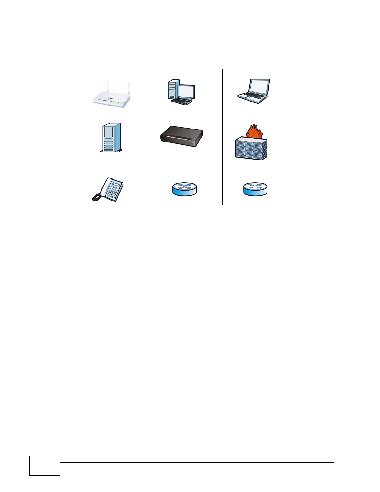
Icons Used in Figures
Figures in this User’s Guide use the following generic icons. The NVG2053 icon is
not an exact representation of your NVG2053.
Graphics in this book may differ slightly from the product due to differences in
operating systems, operating system versions, or if you installed updated
NVG2053 User’s Guide
5
Document Conventions
firmware/software fo r y our dev ice. Ev ery effort has been made to ensur e that the
information in this manual is accurate.
NVG2053 Computer Notebook computer
Server Modem Firewall
Telephone Switch Router
6
NVG2053 User’s Guide

Safety Warnings
Safety Warnings
• Do NOT use this product near water, for example, in a wet basement or n ear a swimming
pool.
• Do NOT expose your device to dampness, dust or corrosive liquids.
• Do NOT store things on the device.
• Do NOT install, use, or service this device during a thunderstorm. There is a remote risk
of electric shock from lightning.
• Connect ONLY suitable accessories to the device.
• Do NOT open the device or unit. Opening or removing covers can expose you to
dangerous high voltage points or other risks. ONLY qualified service personnel should
service or disassemble this device. Please contact your vendor for further information.
• Make sure to connect the cables to the correct ports.
• Place connecting cables carefully so that no one will step on them or stumble over them.
• Always disconnect all cables from this device before servicing or disassembling.
• Use ONLY an appropriate power adaptor or cord for your device.
• Connect the power adaptor or cord to the right supply voltage (for example, 110V AC in
North America or 230V AC in Europe).
• Do NOT allow anything to rest on the power adaptor or cord and do NOT place the
product where anyone can walk on the power adaptor or cord.
• Do NOT use the device if the power adaptor or cord is damaged as it might cause
electrocution.
• If the power adaptor or cord is damaged, remove it from the power outlet.
• Do NOT attempt to repair the power adaptor or cord. Contact your local vendor to order a
new one.
• Do not use the device outside, and make sure all the connections are indoors. There is a
remote risk of electric shock from lightning.
• Do NOT obstruct the device ventilation slots, as insufficient airflow may harm your
device.
• Antenna Warning! This device meets ETSI and FCC certification requirements when using
the included antenna(s). Only use the included antenna(s).
• If you wall mount your device, make sure that no electrical lines, gas or water pipes will
be damaged.
• This CPE product is for indoor use only (utilisation intérieure exclusivement).
Your product is marked with this symbol, which is known as the WEEE mark. WEEE
stands for Waste Electronics and Electrical Equipment. It means that used electrical
and electronic products should not be mixed with general waste. Used electrical and
electronic equipment should be treated separately.
NVG2053 User’s Guide
7

Safety Warnings
8
NVG2053 User’s Guide

Contents Overview
Contents Overview
User’s Guide ........................................................................................................ ...................19
Getting to Know Your NVG2053 ................................................................................................ 21
Tutorials ..................................................................................................................................... 27
Connection Wizard ......... .... ................................................ ... .... ... ............................................. 49
Introducing the Web Configurator .............................................................................................. 59
Technical Reference ..............................................................................................................67
Status Screens .......................................................................................................................... 69
Monitor ...................................... ....................... ...................... ....................... ............................. 75
Broadband ................................................................................................................................. 81
Wireless LAN ............................ ... .... ... ... ............................................. ... .... ... ... ... .... ................... 93
LAN .............................. .................... ................... ................... .................... ..............................121
DHCP Server ...........................................................................................................................125
Quality of Service (QoS) ............................................................................ ... ... ... ..................... 131
Network Address Translation (NAT) ........................................................................................ 139
Dynamic DNS .......................................................................................................................... 145
Static Route ............................................................................................................................. 147
Universal Plug-and-Play (UPnP) ............................................................................................. 151
Firewall .................................................................................................................................... 161
Voice ............................................................ .................................................... ........................167
USB Service .......... .................................................................................................................. 197
Management ....................................... ...................... ....................... ....................... ................. 201
Maintenance ............................................................................................................................ 207
Password ..................................... ....................................................... ..................................... 209
Time .......................................................... .......................................... ......................................211
Firmware Upgrade ................................................................................................................... 215
Backup/Restore ....................................................................................................................... 217
Language ..................................... .................... ................... ................... .................... .............. 221
Restart ..................................................................................................................................... 223
Troubleshooting ..................................................... .................................................................. 225
Product Specifications ............................................................................................................. 231
NVG2053 User’s Guide
9

Contents Overview
10
NVG2053 User’s Guide

Table of Contents
Table of Contents
About This User's Guide..........................................................................................................3
Document Conventions............................................................................................................5
Safety Warnings ........................................................................................................................7
Contents Overview ...................................................................................................................9
Table of Contents....................................................................................................................11
Part I: User’s Guide................................................................................ 19
Chapter 1
Getting to Know Your NVG2053 ............................................................................................21
1.1 Overview ............. ............................................. ... .... ... ... ... .... ................................................ 21
1.2 Applications ............................................... ... ... ... .... ... ... .......................................................21
1.2.1 The WPS Button ................................................. ... .... ... ............................................. 23
1.3 Ways to Manage the NVG2053 ........................................................................................... 23
1.4 Good Habits for Managing the NVG2053 ............................................................................ 23
1.5 LEDs ......................... .... ............................................. ... ... .... ................................................ 24
1.6 Resetting the NVG2053 ......... .... ... ... ... ... .... ... ....................................................................... 25
1.6.1 Procedure to Use the Reset Button ........................................................................... 25
Chapter 2
Tutorials...................................................................................................................................27
2.1 Overview ............. ............................................. ... .... ... ... ... .... ................................................ 27
2.2 Getting Starting with the NVG2053 ...................................................................................... 27
2.3 How to Make a VoIP Call .....................................................................................................28
2.3.1 VoIP Calls With a Registered SIP Account ................................................................ 28
2.4 How to Set up a Secure Wireless Network .......................................................................... 31
2.4.1 Configuring the Wireless Network Settings ............................................................. ... 32
2.4.2 Using WPS ................................... .... ... ... ... .... ... ... ............................................. ... .... ... 34
2.4.3 Without WPS .................................... ... ... ... .... ... ... ... ............................................. .... ...38
2.5 How to Access the NVG2053 Using DDNS ......................................................................... 39
2.5.1 Registering a DDNS Account on www.dyndns.org .................................................... 39
2.5.2 Configuring DDNS on Your NVG2053 ........................................................................ 40
2.5.3 Testing the DDNS Setting ............................................................. ... ... .... ... ................ 40
2.6 How to Route Traffic to Another Network Using Static Route .............................................. 41
NVG2053 User’s Guide
11

Table of Contents
2.7 How to Set Up NAT Port Forwarding ...................................................................................43
2.8 How to Use QoS to Prioritize LAN Traffic ............................................................................ 45
Chapter 3
Connection Wizard .................................................................................................................49
3.1 Overview ............. ............................................. ... .... ... ... ... .... ................................................ 49
3.2 Accessing the Wizard .......................................................................................................... 49
3.3 Connect to Internet ................................ .... ... ... ............................................. .... ... ... ... ..........50
3.3.1 Connection Type: PPPoE .............................................. ... ... ... .... ................................ 51
3.3.2 Connection Type: DHCP ............................... ... ... ... .... ... ... ... ... .... ... ............................. 53
3.3.3 Connection Type: Static IP ..................... .................................................................... 53
3.4 Router Password ................................... .... ... ... ... .... ............................................................. 55
3.5 Wireless Security ................................................................................................................. 55
3.5.1 Wireless Security: No Security ......................... .......................................... ................ 56
3.5.2 Wireless Security: WPA-PSK/WPA2-PSK ........... ... .... ... ... ... ... .... ... ... ... .... ... ... ... ... .... ... 57
Chapter 4
Introducing the Web Configurator ........................................................................................59
4.1 Overview ............. ............................................. ... .... ... ... ... .... ................................................ 59
4.2 Accessing the Web Configurator ......................................................................................... 59
4.2.1 Login Screen ....... ............................................. ... ... .... ... ... ... ... .................................... 60
4.2.2 Password Screen ... ... ... .............................................. ... ... ... ... .... ... ............................. 62
4.3 The Web Configurator Layout .............................................. ... ... ... ... .... ... ... ... .... ... ... ... ... .... ... 63
4.3.1 Navigation Panel .......... .... ... ... ... ................................................................................. 63
4.3.2 Main Window .......................... ... ............................................. .... ... ... ... .... ... ... .............66
4.3.3 Status Bar ............................................... ... .............................................. ... ................ 66
Part II: Technical Reference.................................................................. 67
Chapter 5
Status Screens........................................................................................................................69
5.1 Overview ............. ............................................. ... .... ... ... ... .... ................................................ 69
5.2 Status Screen ............................... ... ... ... .... ... ... ... .............................................. ... ... ... .......... 70
Chapter 6
Monitor.....................................................................................................................................75
12
6.1 Overview ............. ............................................. ... .... ... ... ... .... ................................................ 75
6.1.1 What Yo u Can Do in this Chapter .............................................................................. 75
6.2 The View Log Screen .......................................................................................................... 75
6.3 The Log Settings Screen .................................................................................................... 76
6.4 The DHCP Table Scren ....................................................................................................77
NVG2053 User’s Guide

Table of Contents
6.5 The Packet Statistics Screen ............................................................................................77
6.6 The WLAN Station Status Screen .................................................................................... 79
Chapter 7
Broadband...............................................................................................................................81
7.1 Overview ............. ............................................. ... .... ... ... ... .... ................................................ 81
7.1.1 What Yo u Can Do in this Chapter .............................................................................. 81
7.2 What You Need To Know ................. ... ... .... ... ... ... .... ............................................................. 81
7.3 The Broadband Screen ......................................................................................................83
7.3.1 Broadband Configuration ............. .... ... ... ... .... ... ... ... .... ... ............................................. 84
7.3.2 PPPoE Encapsulation ................................................................................................86
7.4 Technical Reference ............................................................................................................90
Chapter 8
Wireless LAN...........................................................................................................................93
8.1 Overview ............. ............................................. ... .... ... ... ... .... ................................................ 93
8.1.1 What Yo u Can Do in this Chapter .............................................................................. 94
8.2 What You Need to Know ............................... ... ... .... ... ... ... .... ... .............................................94
8.3 General Wireless LAN Screen .............. .... ... ................................................ .... ... ... ............. 97
8.3.1 No Security .......................... ... ............................................. ... .... ... ... ... .... ................... 98
8.3.2 WEP Encryption ..... ... ... .... ... ... .................................................................................... 99
8.3.3 WPA(2)-PSK ............................................................................................................ 101
8.3.4 WPA(2) Authentication .............................. .... ... ... ... .... ... ... ... ... .................................. 102
8.4 MAC Filter ........... ... ... .... ... ... ... .... ............................................. ... ... ... .... ... ... ........................ 104
8.5 Wireless LAN Advanced Screen .................................................. ... .... ... ... ... .... ... ... ... ........105
8.6 Quality of Service (QoS) Screen .......................................................................................107
8.7 WPS Screen ................................. ... ... ... .... ... ... ... .............................................. ... ... ... ........ 107
8.8 WPS Station Screen .......................................................................................................... 109
8.9 Scheduling Screen ................................................. ... ... ... .... ... ... ... ... .... ... ... ... ......................110
8.10 Technical Reference ......................................................................................................... 111
8.10.1 Additional Wireless Terms .......................................................................................111
8.10.2 Wireless Security Overview ....................................................................................111
8.10.3 WiFi Protected Setup ..............................................................................................114
Chapter 9
LAN.........................................................................................................................................121
9.1 Overview ............. ............................................. ... .... ... ... ... .... .............................................. 121
9.2 What You Can Do in this Chapter ......................................................................................121
9.3 What You Need To Know ................. ... ... .... ... ... ... .... ........................................................... 122
9.3.1 Multicast . ... ... ... .............................................. ... ... ... ............................................. ..... 122
9.4 LAN IP Screen ........................... ... ... ... ... .............................................. ... ... ... .... ... ... ...........123
9.5 LAN Advanced Screen ...................................................................................................... 124
NVG2053 User’s Guide
13

Table of Contents
Chapter 10
DHCP Server..........................................................................................................................125
10.1 Overview .......................................................................................................................... 125
10.1.1 What You Can Do in this Chapter .......................................................................... 125
10.2 What You Need to Know .................................................................................................. 125
10.2.1 DHCP ..................................................................................................................... 125
10.2.2 IP Pool Setup .........................................................................................................125
10.3 General Screen ............................................................................................................... 126
10.4 Advanced Screen ......................................................................................................... 126
10.5 Client List Screen ............................................................................................................ 128
Chapter 11
Quality of Service (QoS).......................................................................................................131
11.1 Overview ......................................................................................................................... 131
11.1.1 What You Can Do in this Chapter ...................... ... .... ... ... ... ..................................... 131
11.2 The Quality of Service General Screen .......................................................................... 132
11.2.1 QoS Class Edit ...................................................................................................... 134
11.3 Technical Reference ........................................................................................................ 135
Chapter 12
Network Address Translation (NAT)....................................................................................139
12.1 Overview ....................................................................................................................... 139
12.1.1 What You Can Do in this Chapter .......................................................................... 140
12.2 The General NAT Screen ................................................................................................ 140
12.3 The NAT Port Forwarding Screen .................................................................................. 140
12.3.1 Port Forwarding Edit Screen ................................................................................. 142
Chapter 13
Dynamic DNS ........................................................................................................................145
13.1 Overview ......................................................................................................................... 145
13.1.1 What You Can Do in this Chapter .......................................................................... 145
13.2 What You Need To Know ................................................................................................. 145
13.3 The Dynamic DNS Screen .................................................... ... ... .... ... ... ... .... ... ... ... ... .... . 146
Chapter 14
Static Route...........................................................................................................................147
14.1 Overview ....................................................................................................................... 147
14.1.1 What You Can Do in this Chapter .......................................................................... 147
14.2 The IP Static Route Screen ............................................................................................ 148
14.2.1 Static Route Edit ................................................................................................... 149
Chapter 15
Universal Plug-and-Play (UPnP)..........................................................................................151
14
NVG2053 User’s Guide

Table of Contents
15.1 Overview ......................................................................................................................... 151
15.1.1 What You Can Do in this Chapter .......................................................................... 151
15.2 What You Need to Know .................................................................................................. 151
15.3 The UPnP Screen ............................................................................................................152
15.4 Installing UPnP in Windows .................................. ............................. ............................. . 153
15.4.1 Windows 7 .............................................................................................................. 153
15.4.2 Windows XP ........................................................................................................... 154
15.5 Using UPnP in Windows XP ............................................................................................ 155
15.5.1 Auto-discover Your UPnP-enabled Network Device .............................................. 156
15.5.2 Web Configurator Easy Access ............................................................................. 158
Chapter 16
Firewall...................................................................................................................................161
16.1 Overview ........................................................................................................................ 161
16.1.1 What You Can Do in this Chapter .......................................................................... 161
16.2 What You Need To Know ................................................................................................. 161
16.3 The General Firewall Screen ........................................................................................ 162
16.4 The Services Screen .................. ... ... .... ... ................................................ .... ... ..............163
16.4.1 Configuring Firewall Rules ................................................................................... 164
Chapter 17
Voice.......................................................................................................................................167
17.1 Overview .......................................................................................................................... 167
17.1.1 What You Can Do in this Chapter .......................................................................... 167
17.1.2 What You Need to Know ........................................................................................ 168
17.2 Before You Begin ............................................................................................................. 168
17.3 The SIP Service Provider Screen ................................................................................... 169
17.4 The SIP Account Screen .............. ... ... .... ........................................................................ 172
17.4.1 SIP Account Edit .................................................................................................. 173
17.4.2 Dial Plan Rules ....................................................................................................... 176
17.5 The Phone Device Screen .............................................................................................. 177
17.5.1 The Phone Device Edit Screen .............................................................................178
17.6 The Phone Region Screen .............. ... .... ... ... ... .... ................................................ ... ... .... . 180
17.7 The Speed Dial Screen .................................................. .... ... ... ... ... .... ... ... ... .... ... ... ... ... .... . 180
17.7.1 The Speed Dial Edit Screen ..................................................................................182
17.8 The PSTN call through Screen ....................................................................................... 182
17.9 Technical Reference ........................................................................................................183
17.9.1 Quality of Service (QoS) ........................................................................................ 191
17.9.2 Phone Services Overview ...................................................................................... 192
Chapter 18
USB Service...........................................................................................................................197
18.1 Overview .......................................................................................................................... 197
NVG2053 User’s Guide
15

Table of Contents
18.1.1 What You Can Do in this Chapter .......................................................................... 197
18.2 What You Need to Know .................................................................................................. 197
18.3 Before You Begin ............................................................................................................. 198
18.4 The 3G Connection Setup Screen ................................................................................... 198
Chapter 19
Management..........................................................................................................................201
19.1 Overview .......................................................................................................................... 201
19.1.1 What You Can Do in this Chapter .......................................................................... 201
19.2 What You Need To Know ................................................................................................. 201
19.3 The TR-069 Screen .........................................................................................................202
19.4 The WWW Screen ........................................................................................................... 204
19.5 The Telnet Screen ...........................................................................................................204
19.6 The ICMP Screen ............................................................................................................ 205
Chapter 20
Maintenance..........................................................................................................................207
20.1 Overview .......................................................................................................................... 207
20.2 What You Can Do ............................................................................................................ 207
20.3 General Screen .............................................................................................................. 207
Chapter 21
Password...............................................................................................................................209
21.1 Overview .......................................................................................................................... 209
21.1.1 What You Can Do in this Chapter .......................................................................... 209
21.2 Password Screen ............................................................................................................209
Chapter 22
Time........................................................................................................................................211
22.1 Overview ...........................................................................................................................211
22.1.1 What You Can Do in this Chapter ...........................................................................211
22.2 Time Setting Screen ........................................................................................................ 212
Chapter 23
Firmware Upgrade ................................................................................................................215
23.1 Overview .......................................................................................................................... 215
23.1.1 What You Can Do in this Chapter .......................................................................... 215
23.2 Firmware Upgrade Screen ............................................ .... ... ... ... ... .... ... ... ... .... ... ... ........... 2 15
Chapter 24
Backup/Restore.....................................................................................................................217
24.1 Overview .......................................................................................................................... 217
24.1.1 What You Can Do in this Chapter .......................................................................... 217
16
NVG2053 User’s Guide

Table of Contents
24.2 Backup/Restore Screen ...................................................................................................218
Chapter 25
Language...............................................................................................................................221
25.1 Overview .......................................................................................................................... 221
25.2 What You Can Do ............................................................................................................ 221
25.3 The Language Screen ..................................................................................................... 221
Chapter 26
Restart....................................................................................................................................223
26.1 Overview .......................................................................................................................... 223
26.2 What You Can Do ............................................................................................................ 223
26.3 The Restart Screen .........................................................................................................223
Chapter 27
Troubleshooting....................................................................................................................225
27.1 Power, Hardware Connections, and LEDs .............................. ... ... .... ... ... ... .... ... ... ... ........225
27.2 NVG2053 Access and Login ........................................................................................... 226
27.3 Internet Access ................................................................................................................ 228
27.4 Resetting the NVG2053 to Its Factory Defaults ................................. .............................. 229
27.5 Wireless Router/AP Troubleshooting ...............................................................................230
Chapter 28
Product Specifications.........................................................................................................231
Appendix A Pop-up Windows, JavaScripts and Java Permissions......................................235
Appendix B Setting Up Your Computer’s IP Address...........................................................247
Appendix C Wireless LANs..................................................................................................275
Appendix D Legal Information..............................................................................................291
Appendix E Open Software Announcements.......................................................................295
Index.......................................................................................................................................323
NVG2053 User’s Guide
17

Table of Contents
18
NVG2053 User’s Guide

PART I
User’s Guide
19

20

CHAPTER 1
Getting to Know Your NVG2053
1.1 Overview
This chapter introduces the main features and applications of the NVG2053.
The NVG2053 extends the range of your existing wired network without additional
wiring, providing easy network access to mobile users. You can set up a wireless
network with other IEEE 802.11b/g/n compatible devices.
The NVG2053 supports Voice over IP (VoIP) technology to allow you to use an
analog telephone to make phone calls over the Internet.
The NVG2053 also supports 3G, which allows you to insert a 3G wireless adapter
in the USB port and use the 3G WAN connection as your WAN or a backup to
enhance network reliability.
You can enable NAT and use Quality of Service (QoS) to efficiently manage traffic
on your network by giving priority to certain types of traffic and/or to particular
computers.
1.2 Applications
Your can create the following networks using the NVG2053:
• LAN. You can connect network devices via the Ethernet ports of the NVG2053
so that they can communicate with each other and access the Internet.
• Wireless. Wireless clients can connect to the NVG2053 to access network
resources.
NVG2053 User’s Guide
21
Chapter 1 Getting to Know Your NVG2053
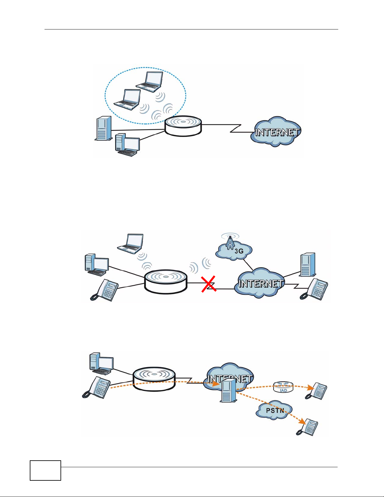
• WAN. Connect to a broadband modem/router for Internet access.
Figure 1 NVG2053 Networks
WLAN
LAN
• 3G WAN. The USB port allows you to wirelessly connect to a 3G netowk to get
Internet access by attaching a 3G wireless adapter. You must leav e the Ethernet
WAN port unconnected and attached a 3G wireless card to use 3G as your WAN.
You can also have the NVG2053 use the 3G WAN connection as a backup. That
means the NVG2053 switches to the 3G wireless WAN connection after the
wired Ethernet WAN connection fails. The NVG2053 automatically changes back
to use the wired Ethernet W A N connection when it is available.
WAN
Figure 2 Internet Access Application: 3G WAN
• VoIP Internet Calls. You can register up to two SIP (Session Initiation
Protocol) accounts and use the NVG2053 to make and receive VoIP telephone
calls. The NVG2053 sends your call to a VoIP service provider’s SIP server (A)
which forwards your calls to either VoIP or PSTN phones.
Figure 3 VoIP Application
22
A
NVG2053 User’s Guide

Chapter 1 Getting to Know Your NVG2053
1.2.1 The WPS Button
You can use the WPS button ( ) on the top panel of the NVG2053 to activate
WPS in order to quickly set up a wireless network with strong security.
1 Make sure the POWER LED is on (not blinking).
2 Press the WPS button for more than three seconds and release it. Press the WPS
button on another WPS-enabled device within range of the NVG2053.
Note: You must activate WPS in the NVG2053 and in another wireless device within
two minutes of each other. See Section 8.10.3 on page 114 for more
information.
1.3 Ways to Manage the NVG2053
Use any of the following methods to manage the NVG2053.
• Web Configurator. This is recommended for everyday management of the
NVG2053 using a (supported) web browser.
• Wireless switch. You can use the built-in switch of the NVG2053 to turn the
wireless function on and off without opening the Web Configur ator.
• WPS (Wi-Fi Protected Setup) button. You can use the WPS button or the WPS
section of the Web Configurator to set up a wireless network with your ZyXEL
Device.
• TR-069. This is an auto-configuration server used to remotely configure your
device.
1.4 Good Habits for Managing the NVG2053
Do the following things regularly to make the NVG2053 more secure and to
manage the NVG2053 more effectively.
• Change the password. Use a password that’s not easy to guess and that consists
of different types of characters, such as numbers and letters.
• Write down the password and put it in a safe place.
• Back up the configuration (and make sure you know how to restore it).
Restoring an earlier working configuration may be useful if the device becomes
unstable or even crashes. If you forget y our password, you will hav e to reset the
NVG2053 to its factory default settings. If you backed up an earlier
configuration file, you would not have to totally re-configure the NVG2053. You
could simply restore your last configuration.
NVG2053 User’s Guide
23
Chapter 1 Getting to Know Your NVG2053
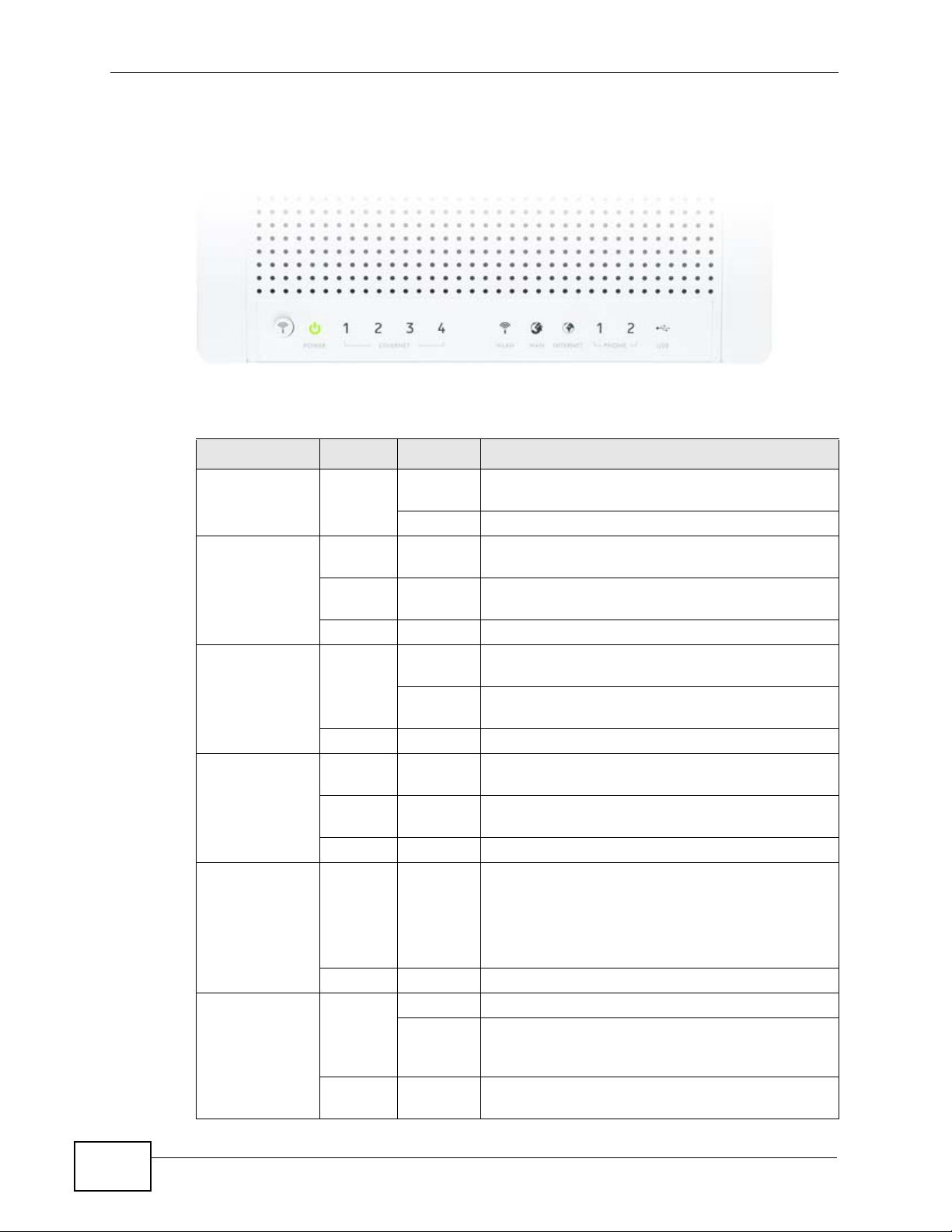
1.5 LEDs
Figure 4 Top Panel
The following table describes the LEDs and the WLAN button.
Table 1 Top Panel LEDs and WPS Button
LED COLOR STATUS DESCRIPTION
POWER Green On The NVG2053 is receiving power and functioning
ETHERNET 1-4 Green On The NVG2053 has a successful 10/100/1000MB
WLAN Green On The NVG2053 is ready, but is not sending/
WAN Green On The NVG2053 has a successful 10/100/1000MB
INTERNET Green On The NVG2053 has an IP connection.
properly.
Off The NVG2053 is not receiving power.
Ethernet connection.
Blinking The NVG2053 is sending/receiving data through
the LAN.
Off The LAN is not connected.
receiving data through the wireless LAN.
Blinking The NVG2053 is sending/receiving data through
the wireless LAN.
Off The wireless LAN is not ready or has failed.
WAN connection.
Blinking The NVG2053 is sending/receiving data through
the WAN.
Off The WAN connection is not ready, or has failed.
24
Your device has a WAN IP address (either static
or assigned by a DHCP server), PPP negotiation
was successfully completed (if used) and the DSL
connection is up.
Off The NVG2053 does not have an IP connection.
PHONE 1/2 Green On A SIP account is registered for the phone port.
Blinking A telephone connected to the phone port has its
receiver off of the hook or there is an incoming
call.
Off The phone port does not have a SIP account
registered.
NVG2053 User’s Guide

Table 1 Top Panel LEDs and WPS Button
LED COLOR STATUS DESCRIPTION
USB Green On The NVG2053 recognizes a USB connection.
Blinking The NVG2053 is sending/receiving data to /from
the USB device connected to it.
Off The NVG2053 does not detect a USB connection.
1.6 Resetting the NVG2053
If you forget your password or IP address, or you cannot access the Web
Configurator, you will need to use the RESET button at the side of the NVG2053 to
reload the factory-default configuration file. This means that you will lose all
configurations that you had prev iously saved, the pass word will be reset to “1234”
and the IP address will be reset to “192.168.1.1”.
Chapter 1 Getting to Know Your NVG2053
1.6.1 Procedure to Use the Reset Button
1 Make sure the power LED is on.
2 Press the RESET button for longer than ten seconds to set the NVG2053 back to
its factory-default configurations.
NVG2053 User’s Guide
25

Chapter 1 Getting to Know Your NVG2053
26
NVG2053 User’s Guide

CHAPTER 2
Tutorials
2.1 Overview
This chapter describes:
• How to Make a VoIP Call (see page 28).
• How to Set up a Secure Wireless Network (see page 31).
• How to Access the NVG2053 Using DDNS (see page 39)
• How to Route Traffic to Another Network Using Static Route (see page 41)
• How to Set Up NAT Port Forwarding (see page 43)
• How to Use QoS to Prioritize LAN Traffic (see page 45)
Note: The tutorials featured in this chapter require a basic understanding of
connecting to and using the Web Configurator on your NVG2053. For details,
see the included Quick Start Guide. For field descriptions of individual screens,
see the related technical reference in this User's Guide.
2.2 Getting Starting with the NVG2053
This quick overview provides pointers on where in this User’ s Guide y ou can go to
get started with configuring and using the NVG2053.
Your NVG2053 may have come pre-configured from your ISP. If
such is the case, changing any network settings may affect your
ability to get online or connect to other computers on your
network.
1 Install the device as described in the included Quick Start Guide.
2 Connect and login to the Web Configur ator at its default IP address as des cribed in
Section 4.2 on page 59. This is where you configure all available s e t ti n g s rel a ted
to your device and its network connections. Y ou will most lik ely need to connect to
the NVG2053 directly from your computer rather than over an existing network,
since the device’s default IP address won’t match that network’ s existi ng topology.
NVG2053 User’s Guide
27

Chapter 2 Tutorials
3 Once you’re in the Web Configurator, you can assign the NVG2053 a new Local
Area Network (LAN) IP address. This allows you to position in your LAN topology
where it is most beneficial to you. See Section 9.4 on page 123 for details.
4 If you were given settings to configure the NVG2053’s WAN connection, then you
can do so in Section 7.3 on page 83.
5 Finally, if you hav e a SIP accou nt and w ant to plac e phone calls o v er the Internet,
see Section 2.3 on page 28.
2.3 How to Make a VoIP Call
The NVG2053 allows you to plug an analog phone into it and place calls over the
Internet to another VoIP device as if you were using an IP Phone or a SIP phone.
Making Internet phone calls requries that first have a SIP account set up with
either your ISP (if they provide such a service) or a third-party SIP provider.
2.3.1 VoIP Calls With a Registered SIP Account
To use a registered SIP account, you should have applied for a SIP account with
the VoIP service provider and got account information from your provider.
This section shows you examples of how to register your SIP account on the
NVG2053 and make Internet calls.
The following table shows the SIP account and SIP server address provided by
your service provider.
SIP Account 12345678@voipprovider.com
SIP Server Address 127.1.2.3
User Name username123
Password password123
2.3.1.1 SIP Account Registration
Follow the steps below to register and activate your SIP account.
1 Make sure your NVG2053 is connected to the Internet.
28
2 Open the web configurator and go to VoIP > SIP.
3 Select the SIP service provider profile you want to configure and give it a name
(“SIPSP-1” for example).
NVG2053 User’s Guide
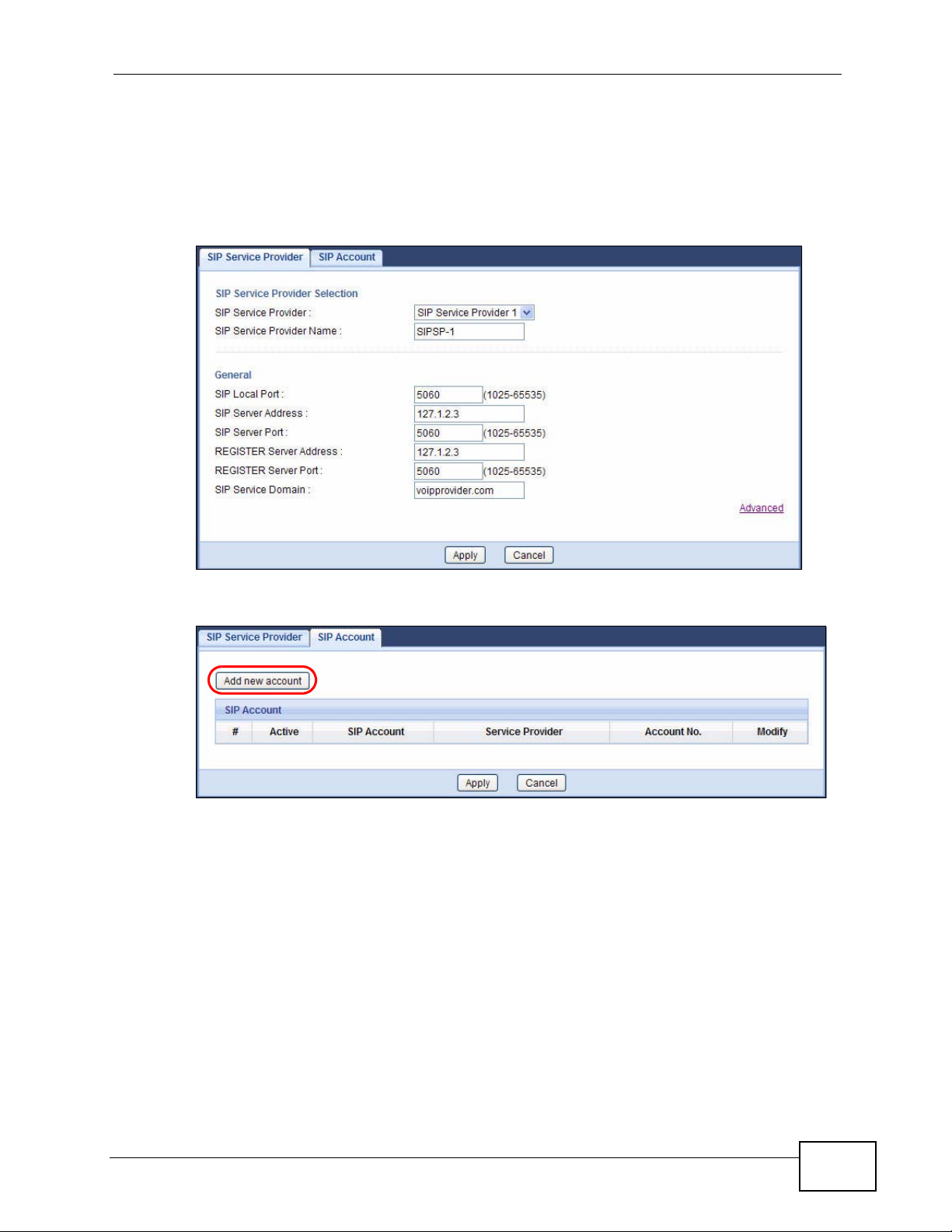
Chapter 2 Tutorials
4 Enter the SIP server address (“127.1.2.3” in this example).
5 Repeat the SIP server address in the REGISTER Server Address field.
6 Enter the SIP server domain (“voipprovider.com” in this example) which is the part
after the @ symbol in your SIP account. Click Apply.
7 Click VoIP > SIP > SIP Account to enter your SIP account information.
8 The NVG2053 allows you to set up multiple SIP accounts. Click the Add new
account button and then select SIP1 to configure the first SIP account.
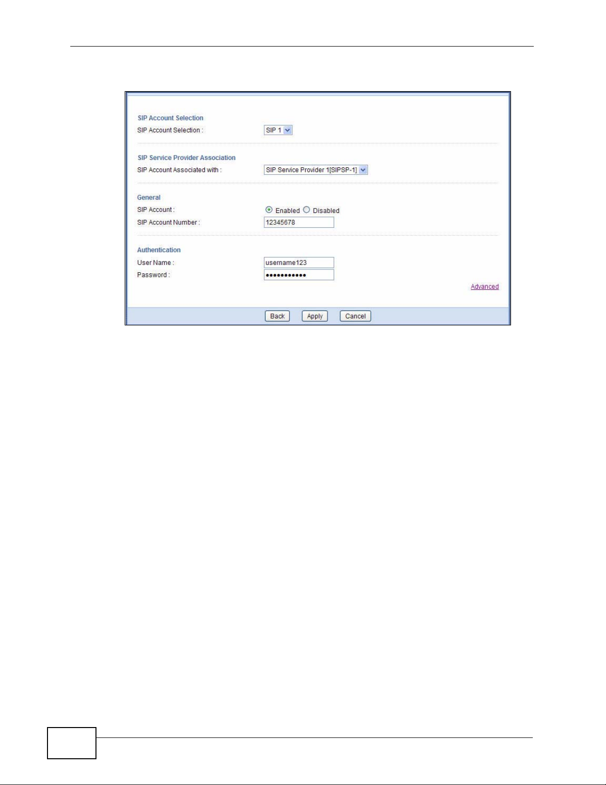
9 Select the name of the SIP service provider profile you just configured.
10 Select the checkbox to enable the SIP account on the NVG2053. If you do not
select this option, then you cannot use the settings configured here for the
selected SIP account.
11 Enter the SIP number (“12345678” in this example) which is the part before the @
symbol in your SIP account.
NVG2053 User’s Guide
29
Chapter 2 Tutorials
12 Enter your user name and password. Click Apply to save your changes.
13 The NVG2053 automatically tries to register your SIP account after you click
Apply. Go to the Status screen, the Status of the FXS1 interface should be
Registered. Check the PHONE LED on the device’s top panel.
2.3.1.2 Analog Phone Configuration
Next, you must configure your Phone settings to bind your newly configured SIP
settings to a single phone.
1 Click VoIP > Phone to open the Phone Device screen.
2 Click the Edit icon of the first entry to configure the first phone port. The phone
you choose corresponds to one of two phones physically connected to your
NVG2053.
3 Select SIP1 in the SIP Account field of the SIP Account to Make Outgoing
Call section to have the phone (connected to the first phone port) use the
registered SIP1 account to make outgoing calls. This means any call sent to the
selected SIP account is forwarded to the phone port configured here.
4 Select the SIP1 checkbox in the SIP Account(s) to Receive Incoming Call
section to have the phone (connected to the first phone port) receive phone calls
for the SIP1 account.
30
NVG2053 User’s Guide

5 Click Apply to save your changes.
Chapter 2 Tutorials
2.3.1.3 Making a VoIP Call
1 Connect a telephone to the first phone port on the NVG2053.
2 Make sure the NVG2053 is on and connected to the Internet.
3 Pick up the handset and hear a dial tone.
4 Dial the SIP phone number you want to call.
2.4 How to Set up a Secure Wireless Network
You want to set up a wireless network so that you can use a notebook to access
the Internet wirelessly. In this wireless ne twork, the NVG2053 serves as an access
point (AP), and the notebook with a wireless network card or USB/PCI adapter is
the wireless client. The wireless client can access the Internet through the AP.
NVG2053 User’s Guide
31

Chapter 2 Tutorials
You have to configure the wireless network settings on the NVG2053. Then you
can set up a wireless network using WPS (Section 2.4.2 on page 34) or manual
configuration (Section 2.4.3 on page 38).
2.4.1 Configuring the Wireless Network Settings
This example uses the following parameters to set up a wireless network.
SSID SSID_Example
Security Mode WPA-PSK
Pre-Shared Key DoNotStealMyWirelessNetwork
Operating Mode IEEE 802.11b/g/n (Mixed)
Follow the steps below to configure the wireless settings on the NVG2053.
1 Open the Network > Wireless LAN > General screen in the NVG2053’s web
configurator. Configure the screen using the provided parameters (see page 32).
2 Make sure the Enable option is selected.
3 Enter “SSID_Example” as the SSID and select Auto Channel Selection to have
the NVG2053 automatically determine a channel which is not used by another AP.
4 Set security mode to WPA-PSK and enter “DoNotStealMyWirelessNetwork” in the
Pre-Shared Key field. Click Apply.
32
NVG2053 User’s Guide

Chapter 2 Tutorials
5 Go to the Wireless LAN > Advanced screen, and make sure the Operating
Mode is set to Mixed. Click Apply.
6 Open the Status screen.Verify your wireless and wireless security settings under
Device Information and check if the WLAN connection is up under Interface
Status.
NVG2053 User’s Guide
33

Chapter 2 Tutorials
7 You can now use the WPS feature to establish a wireless connection between his
notebook and the NVG2053 (see Section 2.4.2 on page 34). You can also use the
notebook’s wireless client to search for the NVG2053 (see Section 2.4.3 on page
38).
8 Click the WLAN Station Status hyperlink in the Status screen. You can see if
any wireless client has connected to the NVG2053.
2.4.2 Using WPS
This section shows you how to set up a wireless network using WPS. It uses the
NVG2053 as the AP and ZyXEL NWD210N as the wireless client which connects to
the notebook.
Note: The wireless client must be a WPS-aware device (for example, a WPS USB
adapter or PCMCIA card).
There are two WPS methods to set up the wireless client settings:
• Push Button Configuration (PBC) - simply press a button. This is the easier
of the two methods.
• PIN Configuration - configure a Personal Identification Number (PIN) on the
NVG2053. A wireless client must also use the same PIN in order to download the
wireless network settings from the NVG2053.
Push Button Configuration (PBC)
1 Make sure that your NVG2053 is turned on and your notebook is within the cover
range of the wireless signal.
2 Make sure that you have installed the wireless client driver and utility in your
notebook.
34
3 Press the WPS button on your notebook within range of the NVG2053.
NVG2053 User’s Guide

Chapter 2 Tutorials
4 The wireless LAN of the NVG2053 is enabled by default, so the WLAN LED lights
green. If not, push the WLAN switch to the ON position on the rear panel. When
the LED turns green, the wireless L AN is on. Then press the WPS button for more
than three seconds and release it.
5 Alternatively, you may log into NVG2053’s web configurator and click the Push
Button in the Network > Wireless LAN > WPS Station screen.
Note: Your NVG2053 has a WPS button located on its top panel as well as a WPS
button in its configuration utility. Both buttons have exactly the same function:
you can use one or the other.
Note: It doesn’t matter which button is pressed first. You must press the second
button within 120 seconds of pressing the first one.
NVG2053 User’s Guide
35

Chapter 2 Tutorials
The following figure shows you an example of how to set up a wireless network
and its security by pressing a button on both NVG2053 and wireless client.
Example WPS Process: PBC Method
Wireless Client
Access Point
WITHIN 120 SECONDS
Press and hold for
more than 3 seconds
SECURITY INFO
COMMUNICATION
36
NVG2053 User’s Guide

Chapter 2 Tutorials
PIN Configuration
When you use the PIN configuration method, you need t o use both the NVG2053’ s
web configurator and the wireless client’ s utility.
1 Launch your wireless client’s configuration utility. Go to the WPS settings and
select the PIN method to get a PIN number.
2 Enter the PIN number in the PIN field in the Network > Wireless LAN > WPS
Station screen on the NVG2053.
3 Click the Start buttons (or the button next to the PIN field) on both the wireless
client utility screen and the NVG2053’s WPS Station screen within two minutes.
The NVG2053 authenticates the wireless client and sends the proper configuration
settings to the wireless client. This may take up to two minutes. The wireless
client is then able to communicate with the NVG2053 securely.
NVG2053 User’s Guide
37

Chapter 2 Tutorials
The following figure shows you how to set up a wireless network and its security
on a NVG2053 and a wireless client by using PIN method.
Example WPS Process: PIN Method
Wireless Client
Access Point
WITHIN 2 MINUTES
2.4.3 Without WPS
Use the wireless adapter’s utility installed on the notebook to search for the
“SSID_Example” SSID. Then enter the “DoNotStealMyWirelessNetwork” preshared key to establish an wireless Internet connection.
38
Authentication by PIN
SECURITY INFO
COMMUNICATION
NVG2053 User’s Guide

Chapter 2 Tutorials
Note: The NVG2053 supports IEEE 802.11b, IEEE 802.11g and IEEE 802.11n
wireless clients. Make sure that your notebook or computer’s wireless adapter
supports one of these standards.
2.5 How to Access the NVG2053 Using DDNS
If you connect your NVG2053 to the Internet and it uses a dynamic WAN IP
address, it is inconvenient for you to manage the device from the Internet. The
NVG2053’s WAN IP address changes dynamically. Dynamic DNS (DDNS) allows
you to access the NVG2053 using a domain name.
http://zyxelrouter.dyndns.org
A
w.x.y.z
To use this feature, you have to apply for DDNS service at www.dyndns.org.
This tutorial shows you how to:
• Registering a DDNS Account on www.dyndns.org
• Configuring DDNS on Your NVG2053
• Testing the DDNS Setting
a.b.c.d
Note: If you have a private WAN IP address, then you cannot use DDNS.
2.5.1 Registering a DDNS Account on www.dyndns.org
1 Open a browser and type http://www.dyndns.org.
2 Apply for a user account. This tutorial uses “UserName1” and “12345” as the
username and password.
3 Log into www.dyndns.org using your account.
4 Add a new DDNS host name. This tutorial uses the following settings as an
example.
• Hostname: zyxelrouter.dyndns.org
• Service Type: Host with IP address
NVG2053 User’s Guide
39

Chapter 2 Tutorials
• IP Address: Enter the WAN IP address that your NVG2053 is currently using.
You can find the IP address on the NVG2053’s Web Configurator Status page.
Then you will need to configure the same account and host name on the NVG2053
later.
2.5.2 Configuring DDNS on Your NVG2053
1 Log into the NVG2053's advanced mode.
2 Configure the following settings in the Network > Dynamic DNS screen.
2a Select Enable DDNS.
2b Select WWW.DynDNS.ORG in the Service Provider field.
2c Type “zyxelrouter.dyndns.org” in the Domain Name field.
2d Enter the user name (“UserName1” for example) and password (“12345” for
example).
2e Select Use WAN IP Address for the IP address update policy.
2f Click Apply.
2.5.3 Testing the DDNS Setting
Now you should be able to access the NVG2053 from the Internet. To test this:
40
1 Open a web browser on the computer (using the IP address a.b.c.d) that is
connected to the Internet.
2 Type “http://zyxelrouter.dyndns.org” and press [Enter].
NVG2053 User’s Guide

Chapter 2 Tutorials
3 The NVG2053’s login page should appear. Y ou can then l og into the NVG2053 and
manage it.
2.6 How to Route Traffic to Another Network
Using Static Route
In order to extend your Intranet and control traffic flow directions, you may
connect a router (R) to the NVG2053’s LAN. The router may be used to separate
two department networks. This tutorial shows how to configure a static routing
rule for two network routings.
In the following figure, router R is connected to the NVG2053’ s LAN. R connects to
two networks, N1 (192.168.1.x/24) and N2 (192.168.10.x/24). If you want to
send traffic from computer A (in N1 network) to computer B (in N2 network), the
traffic is sent to the NVG2053’s WAN default gateway by default. In this case, B
will never receive the traffic.
N1
A
R
N2
B
NVG2053 User’s Guide
41

Chapter 2 Tutorials
You need t o specify a static routing rule on the NVG2053 to specif y R as the router
in charge of forwarding traffic to N2. In this case, the NVG2053 routes traffic from
A to R and then R routes the traffic to B.
N1
This tutorial uses the following example IP settings:
A
R
N2
B
Table 2 IP Settings in this Tutorial
DEVICE / COMPUTER IP ADDRESS
The NVG2053’s WAN 172.16.1.1
The NVG2053’s LAN 192.168.1.1
A 192.168.1.34
R’s N1 192.168.1.253
R’s N2 192.168.10.2
B 192.168.10.33
To configure a static route to route traffi c from N1 to N2:
1 Log into the NVG2053’s Web Configurator.
2 Click Configuration > Network > Static Route.
3 Click the Add Static Route button to create a new rule.
42
4 Configure the Static Route > Edit screen using the following settings:
NVG2053 User’s Guide

Chapter 2 Tutorials
4a Select Enable.
4b Specify a descriptive name for this routing rule.
4c Type “192.168.10.0” and select subnet mask “255.255.255.0” for the
destination, N2.
4d Type “192.168.1.253” (R’s N1 address) in the Gateway IP Address field.
4a Click Apply.
Now B should be able to receive traffic from A. You may need to additionally
configure B’s firewall settings to allow specific traffic to pass through.
2.7 How to Set Up NAT Port Forwarding
You manage the Doom server on a computer behind the NVG2053. In order for
players on the Internet to communicate with the Doom server, you need to
configure the port settings and IP address on the NVG2053. Traffic should be
forwarded to the port 666 of the Doom server computer which has an IP address
of 192.168.1.34.
D=192.168.1.34
666
LAN
WAN
NVG2053 User’s Guide
43

Chapter 2 Tutorials
1 Click Configuration > Network > NAT to open the General screen. Make sure
it is selected to enable NAT on the NVG2053 and click Apply.
2 Click the Port Forwarding tab to open the following screen. Click the Add Port
Forward button to create a new rule.
3 Configure the screen as follows to forward port 66 6 traffic to the computer with IP
address 192.168.1.34. Click Apply.
4 The port forwarding settings you configured are listed in the Port Forwarding
screen.
44
NVG2053 User’s Guide

Chapter 2 Tutorials
Players on the Internet then can have access to the Doom server.
2.8 How to Use QoS to Prioritize LAN Traffic
In this example, your Internet connection has an upstream transmission speed of
50 Mbps. You want to configure a QoS class to assign the high priority queue (6)
to VoIP traffic from the phone port(s), so that voice traffic will not get delayed
when there is network congestion. Traffic from the boss’s IP address
(192.168.1.101 for example) is mapped to queue 5. Traffic that does not match
these two classes are assigned priority queue based on the DSCP value in the
packets.
VoIP: Queue 6
50 Mbps
Boss: Queue 5
IP = 192.168.1.101
NVG2053 User’s Guide
45

Chapter 2 Tutorials
1 Click Configuration > DHCP Server > Advanced. Enter the MAC address of the
boss’s computer (“00:A0:C5:01:23:45” for example) in the MAC Address field
and 192.168.1.101 in the IP Address field to have the NVG2053 always assign
the IP address 192.168.1.101 to the boss’s computer. Click Apply.
2 Click Network > QoS and select the Enabled option to turn on QoS on the
NVG2053.
Set DSCP to ON to have the NVG2053 assign priority to unmatched traffic based
on the DSCP value in the packets. Click Apply.
46
NVG2053 User’s Guide

Chapter 2 Tutorials
3 Click Add new Class in the QoS > General scren to create a QoS class for VoIP
traffic.
4 Give the class a name (“VoIP” for example).
Set Priority to 6.
Select From Interface and then FXS from the drop-down list to group traffic
coming from the phone port(s) on the NVG2053.
Leave all other fields as the default and click Apply.
5 Click Add new Class in the QoS > General scren to create a QoS class for traffic
from the boss’s IP address (10.1.1.23 in this example).
NVG2053 User’s Guide
47

Chapter 2 Tutorials
6 Give the class a name (“Boss” for example).
Set Priority to 5.
Select From Interface and the interface to which the boss’s computer is
connected (WLAN in this example as he or she has a wireless connection to the
NVG2053).
Select Source Address and then enter the boss’s IP address in the field provided.
Leave all other fields as the default and click Apply.
48
VoIP traffic now should have higher priority and get through faster than the boss’s
traffic.
NVG2053 User’s Guide

CHAPTER 3
Connection Wizard
3.1 Overview
This chapter provides information on the wizard setup screens in the Web
Configurator.
The Web Configurator’ s wizard setup helps you configure your device to access the
Internet. Refer to your ISP for your Internet account information. Leave a field
blank if you don’t have that information.
3.2 Accessing the Wizard
Launch your web browser and type "http://192.168.1.1" as the website address.
Note: The Wizard appears when the NVG2053 is accessed for the first time or when
you reset the NVG2053 to its default factory settings.
The Wizard screen opens. Choose your Language and click Connect to
Internet.
Figure 5 Welcome
NVG2053 User’s Guide
49

Chapter 3 Connection Wizard
Note: If you have already configured the wizard screens and want to open it again,
click the eaZy123 icon on the upper right corner of any Web Configurator
screen.
3.3 Connect to Internet
The NVG2053 offers three Internet connection types. They are Static IP, DHCP,
and PPPoE. The wizard attempts to detect which WAN connection type you are
using.
Figure 6 Detecting your Internet Connection Type
If the wizard does not detect a connection type, you must select one from the
drop-down list box. Check with your ISP to make sure you use the correct type.
Note: If you get an error message, check your hardware connections. Make sure your
Internet connection is up and running.
50
NVG2053 User’s Guide

Chapter 3 Connection Wizard
The following screen depends on your Internet connection type. Enter the details
provided by your Internet Service Provider (ISP) in the fields (if any).
Figure 7 Internet Connection Type
Your NVG2053 detects the following Internet Connection type.
Table 3 Internet Connection Type
CONNECTION
TYPE
PPPoE Select the PPPoE (Point-to-Point Protocol over Ethernet) option for
DHCP Select the DHCP (Dynamic Host Configuration Protocol) option
Static IP Select the Static IP if an administrator assigns the IP address of
DESCRIPTION
a dial-up connection.
when the WAN port is used as a regular Ethernet.
your computer.
3.3.1 Connection Type: PPPoE
Point-to-Point Protocol over Ethernet (PPPoE) functions as a dial-up connection.
PPPoE is an IETF (Internet Engineering T ask Force) standard specif ying how a host
personal computer interacts with a broadband modem (for example DSL, cable,
wireless, etc.) to achieve access to high-speed data networks.
For the service provider, PPPoE offers an access and authentication method that
works with existing access control systems (for instance, RADIUS).
One of the benefits of PPPoE is the ability to let end users acce ss one of multiple
network services, a function known as dynamic service selection. This enables the
service provider to easily create and offer new IP services for specific users.
NVG2053 User’s Guide
51

Chapter 3 Connection Wizard
Operationally, PPPoE saves significant effort for both the subscriber and the ISP/
carrier, as it requires no specific configuration of the broadband modem at the
subscriber's site.
By implementing PPPoE directly on the NVG2053 (rather than individual
computers), the computers on the LAN do not need PPPoE software installed,
since the NVG2053 does that part of the task. Furthermore, with NAT, all of the
LAN's computers will have Internet access.
Figure 8 Internet Connection Type: PPPoE
The following table describes the labels in this screen.
Table 4 Internet Connection Type: PPPoE
LABEL DESCRIPTION
Internet
Connection
Type
Username Type the user name given to you by your ISP.
Password Type the password associated with the user name above.
Exit Click this to close the wizard screen without saving.
Back Click this to return to the previous screen.
Next Click this to continue.
Select the PPPoE option for a dial-up connection.
52
NVG2053 User’s Guide

3.3.2 Connection Type: DHCP
Choose DHCP as the Internet Connection Type when the WAN port is used as a
regular Ethernet. Click Next.
Figure 9 Internet Connection Type: DHCP
Chapter 3 Connection Wizard
Note: If you get an error screen after clicking Next, you might have selected the
wrong Internet connection type. Click Back, make sure your Internet
connection is working and select the right connection type. Contact your ISP if
you are not sure of your Internet connection type.
3.3.3 Connection Type: Static IP
Choose Static IP as the Internet Connection Type if your ISP assigned an IP
address for your Internet connection. Click Next.
Figure 10 Internet Connection Type: Static IP
NVG2053 User’s Guide
53

Chapter 3 Connection Wizard
The following table describes the labels in this screen.
Table 5 Internet Connection Type: Static IP
LABEL DESCRIPTION
Internet
Connection Type
IP Address Enter the IP address provided by your ISP.
Subnet Mask Enter the IP subnet mask in this field.
Default Gateway Enter the gateway IP address in this field.
Primary DNS DNS (Domain Name System) is for mapping a domain name to its
Secondary DNS Enter the secondary DNS server's IP address in the fields provided.
Exit Click this to close the wizard screen without saving.
Back Click this to return to the previous screen.
Next Click this to continue.
Select the Static IP option.
corresponding IP address and vice versa. The DNS server is
extremely important because without it, you must know the IP
address of a computer before you can access it. The NVG2053 uses a
system DNS server (in the order you specify here) to resolve domain
names for DDNS and the time server.
Enter the primary DNS server's IP address in the fields provided.
The NVG2053 connects to the Internet.
Figure 11 Connecting to the Internet
Note: If the Wizard successfully connects to the Internet, it proceeds to the next step.
If you get an error message, go back to the previous screen and make sure you
have entered the correct information provided by your ISP.
54
NVG2053 User’s Guide

3.4 Router Password
Change the login password in the following screen. Enter the new password and
retype it to confirm. Click Next to proceed with the Wireless Security screen.
Figure 12 Router Password
Chapter 3 Connection Wizard
3.5 Wireless Security
Configure Wireless Settings. Configure the wireless network settings on your
NVG2053 in the following screen. The fields that show up depend on the kind of
security you select.
NVG2053 User’s Guide
55

Chapter 3 Connection Wizard
3.5.1 Wireless Security: No Security
Choose No Security in the Wireless Security screen to let wireless devices
within range access your wireless network.
Figure 13 Wireless Security: No Security
The following table describes the labels in this screen.
Table 6 Wireless Security: No Security
LABEL DESCRIPTION
Wireless
Network
Name
(SSID)
Security
mode
Exit Click this to close the wizard screen without saving.
Back Click this to return to the previous screen.
Next Click this to continue.
Enter a descriptive name (up to 32 printable 7-bit ASCII characters) for the
wireless LAN.
If you change this field on the NVG2053, make sure all wireless stations
use the same SSID in order to access the network.
Select a security level from the drop-down list box.
Choose None to have no wireless LAN security configured. If you do not
enable any wireless security on your NVG2053, your network is accessible
to any wireless networking device that is within range.
56
NVG2053 User’s Guide

Chapter 3 Connection Wizard
3.5.2 Wireless Security: WPA-PSK/WPA2-PSK
Choose WPA-PSK or WPA2-PSK security in the Wireless Security screen to set
up a password for your wireless network.
Figure 14 Wireless Security: WPA-PSK/WPA2-PSK
The following table describes the labels in this screen.
Table 7 Wireless Security: WPA-PSK/WPA2-PSK
LABEL DESCRIPTION
Wireless
Network
Name
(SSID)
Security
mode
Wireless
password
Verify
Password
Exit Click this to close the wizard screen without saving.
Back Click this to return to the previous screen.
Next Click this to continue.
Congratulations! Open a web browser, such as Internet Explorer, to visit your
favorite website.
Enter a descriptive name (up to 32 printable 7-bit ASCII characters) for the
wireless LAN.
If you change this field on the NVG2053, make sure all wireless stations
use the same SSID in order to access the network.
Choose WPA-PSK or WPA2-PSK security to configure a Pre-Shared Key.
Choose this option only if your wireless clients support WPA-PSK or WPA2PSK respectively.
T ype from 8 to 63 case-sensitive ASCII characters. You can set up the most
secure wireless connection by configuring WPA in the wireless LAN screens.
Retype the password to confirm.
NVG2053 User’s Guide
57

Chapter 3 Connection Wizard
Note: If you cannot access the Internet when your computer is connected to one of
the NVG2053’s LAN ports, check your connections. Then turn the NVG2053
off, wait for a few seconds then turn it back on. If that does not work, log in to
the web configurator again and check you have typed all information correctly.
Figure 15 Congratulations
You have successfully set up your NVG2053 to operate on your network and
access the Internet. You are now ready to connect wirelessly to your NVG2053
and access the Internet.
You can click GO to open the login screen to acess the Web Configurator of your
NVG2053 for advanced settings.
58
NVG2053 User’s Guide

CHAPTER 4
Introducing the Web
Configurator
4.1 Overview
This chapter describes how to access the NVG2053 W eb Configurator and provides
an overview of its screens.
The Web Configurator is an HTML-based management interface that allows easy
setup and management of the NVG2053 via Internet browser. Use Internet
Explorer 6.0 and later versions or Mozilla Firefox 3 and later versions. The
recommended screen resolution is 1024 by 768 pixels.
In order to use the Web Configurator you need to allow:
• Web browser pop -up windows from your device. W eb pop-up blocking is enabl ed
by default in Windows XP SP (Service Pack) 2.
• JavaScript (enabled by default).
• Java permissions (enabled by default).
Refe r to Appendix A on page 235 to see how to make sure these functions are
allowed in Internet Explorer.
4.2 Accessing the Web Configurator
1 Make sure your NVG2053 hardware is properly connected and prepare your
computer or computer network to connect to the NVG2053 (refer to the Quick
Start Guide).
2 Launch your web browser.
3 Type "http://192.168.1.1" as the website address.
Your computer must be in the same subnet in order to access this website
address.
NVG2053 User’s Guide
59

Chapter 4 Introducing the Web Configurator
4.2.1 Login Screen
Note: If this is the first time you are accessing the Web Configurator, you may be
redirected to the Wizard. Refer to Chapter 3 on page 49 for the Connection
Wizard screens.
The Web Configurator initially displays the following login screen.
Figure 16 Login screen
The following table describes the labels in this screen.
Table 8 Login screen
LABEL DESCRIPTION
Language Select the language you want to use to configure the Web Configurator.
Password Type "1234" (default) as the password.
4.2.1.1 Weather Edit
You can change the temperature unit and select the location for which you want to
know the weather.
Click Login.
This shows the current weather, either in celsius or fahrenheit, of the
city you specify in Section 4.2.1.1 on page 60.
This shows the time (hh:mm) and date (yyyy/mm/dd) of the timezone
you select in Section 4.2.1.2 on page 61 or Section 22.2 on page 212.
The time is in 24-hour format, for example 15:00 is 3:00 PM.
60
NVG2053 User’s Guide

Chapter 4 Introducing the Web Configurator
Click the icon to change the Weather display.
Figure 17 Change Weather
The following table describes the labels in this screen.
Table 9 Change Weather
LABEL DESCRIPTION
Change Unit Choose which temperature unit you want the NVG2053 to display.
Change location Select the location for which you want to know the weather. If the city
you want is not listed, choose one that is closest to it.
Finish Click this to apply the settings and refresh the date and time display.
4.2.1.2 Time/Date Edit
One timezone can cover more than one country. You can choose a particular
country in which the NVG2053 is located and have the NVG2053 display and use
the current time and date for its logs.
Click the icon to change the time and date display.
Figure 18 Change Time Zone Screen
The following table describes the labels in this screen.
Table 10 Change Time Zone Screen
LABEL DESCRIPTION
Change time
zone
Finish Click this to apply the settings and refresh the weather display.
Select the specific country whose current time and date you want the
NVG2053 to display.
Note: You can also edit the timezone in Section 22.2 on page 212.
NVG2053 User’s Guide
61

Chapter 4 Introducing the Web Configurator
4.2.2 Password Screen
You should see a screen asking you to change your password (highly
recommended) as shown next.
Figure 19 Change Password Screen
The following table describes the labels in this screen.
Table 11 Change Password Screen
LABEL DESCRIPTION
New Password Type a new password.
Retype to
Confirm
Apply Click Apply to save your changes back to the NVG2053.
Ignore Click Ignore if you do not want to change the password this time.
Retype the password for confirmation.
Note: The management session automatically times out when the time period set in
the Administrator Inactivity Timer field expires (default five minutes; go to
Chapter 20 on page 207 to change this). Simply log back into the NVG2053 if
this happens.
Right after you log in, the Status screen is displayed. See Chapter 4 on page 81
for more information about the Status screen.
62
NVG2053 User’s Guide

Chapter 4 Introducing the Web Configurator
4.3 The Web Configurator Layout
Figure 20 The Web Configurator Layout
B
C
A
D
As illustrated above, the Web Configurator screen is divided into these parts:
• A - title bar
• B - navigation panel
• C - main window
• D - status bar
4.3.1 Navigation Panel
Use the menu items on the navigation panel to open screens to configure
NVG2053 features. The following tables describe each menu item.
Table 12 Navigation Panel Summary
LINK TAB FUNCTION
Status
Status This screen shows the NVG2053’s general device and network
status information. Use this screen to access the statistics and
client list.
Monitor
NVG2053 User’s Guide
63

Chapter 4 Introducing the Web Configurator
Table 12 Navigation Panel Summary
LINK TAB FUNCTION
Log View Log Use these screens to view the logs for the categories that you
Log Settings
DHCP Table Use this screen to view information related to your DHCP status.
Packet Statistics Use this screen to view port status, packet specific statistics, the
WLAN Station
Status
Configuration
Network
Broadband Use this screen to add or remove a WAN connection and configure
Wireless LAN General Use this screen to configure the wireless LAN settings and WLAN
LAN IP Use this screen to configure NVG2053’s LAN IP address.
DHCP Server General Use this screen to enable the DHCP server for the LAN.
QoS General Use this screen to enable QoS and define QoS classes.
NAT General Use this screen to enable NAT.
Dynamic DNS This screen allows you to use a static hostname alias for a
Static Route Use this screen to configure IP static routes to tell your device
UPnP Use this screen to turn UPnP on or off.
Security
Firewall General Use this screen to activate/deactivate the firewall.
Association
List
MAC Filter Use this screen to configure MAC filtering rules.
Advanced Use this screen to configure the advanced wireless LAN settings.
QoS WMM QoS allows you to prioritize wireless traffic according to the
WPS Use this screen to enable WPS (Wi-Fi Protected Setup) and view
WPS Station Use this screen to use WPS to set up your wireless network.
Scheduling Use this screen to configure the times to enable or disable the
Advanced Use this screen to enable IP multicasting for your NVG2053 LAN
Advanced Use this screen to to always assign specific IP addresses to
Client List Use this screen to view current DHCP client information and to
Port
Forwarding
selected and change your log settings.
"system up time" and so on.
Use this screen to view the wireless stations that are currently
associated to the NVG2053.
ISP parameters, WAN IP address assignment, and other adv anced
properties
authentication/security settings.
delivery requirements of individual services.
the WPS status.
wireless LAN.
interface.
individual MAC addresses (and host names).
always assign specific IP addresses to individual MAC addresses
(and host names).
Use this screen to make your local servers visible to the outside
world.
dynamic IP address.
about networks beyond the directly connected remote nodes.
64
NVG2053 User’s Guide

Chapter 4 Introducing the Web Configurator
Table 12 Navigation Panel Summary
LINK TAB FUNCTION
Services This screen shows a summary of the firewall rules, and allows you
to edit/add a firewall rule.
VoIP
SIP SIP Service
Provider
SIP Account Use this screen to congiure your SIP account information, dialing
Phone Phone Device Use this screen to set which phone ports use which SIP accounts
Region Use this screen to select your location and call service mode.
Call Rules Speed Dial Use this screen to configure speed dial for SIP phone numbers
PSTN call
through
USB Services 3G Connection
Setup
Management
TR069 TR069
Configuration
Remote
MGMT
Maintenance
General Use this screen to configure your device’s name, domain name,
Password Password
Time Time Setting Use this screen to change your NVG2053’s time and date.
Firmware
Upgrade
Backup/
Restore
Language Use this screen to change the Web Configurator’s display
Restart Use this screen to reboot the NVG2053 without turning the power
WWW Use this screen to configure through which interface(s) and from
Telent Use this screen to configure through which interface(s) and from
ICMP Use this screen to set whether or not your device will respond to
Setup
Use this screen to configure the SIP server information, QoS for
VoIP calls and dialing interval and timer settings.
plan rules and call features.
and general phone port settings.
that you call often.
Use this screen to configure your NVG2053’s settings for regular
PSTN calls.
Use this screen to configure the 3G WAN connection.
Use this screen to configure the NVG2053 to be managed by an
ACS (Auto Configuration Server).
which IP address(es) users can use HTTP to manage the
NVG2053.
which IP address(es) users can use Telnet to manage the
NVG2053.
pings.
and management inactivity timeout.
Use this screen to configure your device’s password.
Use this screen to upload firmware to your device.
Use this screen to backup and restore your device’s configuration
(settings) or reset the factory default settings.
language.
off.
NVG2053 User’s Guide
65

Chapter 4 Introducing the Web Configurator
4.3.2 Main Window
The main window displays information and configuration fields. It is discussed in
the rest of this document.
4.3.3 Status Bar
Check the status bar when you click Apply or OK to verify that the configuration
has been updated.
66
NVG2053 User’s Guide

PART II
Technical Reference
67

68

CHAPTER 5
Status Screens
5.1 Overview
Use the Status screens to look at the current status of the device, system
resources and interfaces (LAN, WAN, WLAN and 3G). The Status screen also
provides statistics from traffic.
NVG2053 User’s Guide
69

Chapter 5 Status Screens
5.2 Status Screen
Click Status to open this screen.
Figure 21 Status Screen
70
Each field is described in the following table.
Table 13 Status Screen
LABEL DESCRIPTION
Refresh Interval Enter how often you want the NVG2053 to update this screen.
Refresh Now Click this to update this screen immediately.
Device
Information
Host Name This field displays the NVG2053 system name. It is used for
identification. Click this to go to the screen where you can change it.
Model
Number
Firmware
Version
WAN
Information
This is the model name of your device.
This field displays the current version of the firmware inside the device.
It also shows the date the firmware version was created.
NVG2053 User’s Guide

Chapter 5 Status Screens
Table 13 Status Screen
LABEL DESCRIPTION
MAC Address This is the MAC (Media Access Control) or Ethernet address unique to
your NVG2053. This MAC is used for the WAN connection and is
different from the LAN or WLAN MAC.
IP Address This field displays the current IPv4 address of the NVG2053 in the
WAN.
IP Subnet
Mask
Default
Gateway
EncapsulationThis field displays the method of encapsulation used by the WAN
LAN Information
MAC Address This is the MAC (Media Access Control) or Ethernet address unique to
IP Address This field displays the current IPv4 address of the NVG2053 in the LAN.
IP Subnet
Mask
DHCP This field displays whether the NVG2053 acts as a DHCP server and
This field displays the current subnet mask in the WAN.
This field displays the IP address of the default gateway, if applicable.
connection.
your NVG2053. This MAC is used for LAN connections and differs from
the WLAN or WAN MAC.
Click this to go to the screen where you can change it.
This field displays the current subnet mask in the LAN.
assigns IP addresses to other computers in the LAN (Enable) or not
(Disable).
Click this to go to the screen where you can change it.
WLAN
Information
MAC Address This is the MAC (Media Access Control) or Ethernet address unique to
your NVG2053. This MAC is used for WLAN connections and differs
from the LAN or WAN MAC.
SSID This is the descriptive name used to identify the NVG2053 in this
wireless network. Click this to go to the screen where you can change
it.
Channel This is the channel number used by the NVG2053 now.
Security This shows the level of wireless security the NVG2053 is using in this
wireless network.
Security Mode
Firewall This displays whether or not the NVG2053’s firewall is activated. Click
this to go to the screen where you can change it.
Summary
Packet
Statistics
WLAN Station
Status
System Status
Click this link to view packet specific statistics of the WAN
connection(s). See Section 6.5 on page 77.
Click this link to display the MAC address(es) of the wireless stations
that are currently associating with the NVG2053. See Section 6.6 on
page 79.
NVG2053 User’s Guide
71

Chapter 5 Status Screens
Table 13 Status Screen
LABEL DESCRIPTION
System
Uptime
Current
Date/Time
System
Resource
CPU Usage This field displays what percentage of the NVG2053’s processing ability
Memory
Usage
Interface Status
Interface This column displays each interface the NVG2053 has.
Status This field indicates whether or not the NVG2053 is using the interface.
This field displays how long the NVG2053 has been running since it last
started up. The NVG2053 starts up when you plug it in, when you
restart it, or when you reset it using the Maintenance > Backup/
Restore screen or the RESET button (see Section 1.6 on page 25).
This field displays the current date and time in the NVG2053. You can
change this in Maintenance > Time.
is currently used. When this percentage is close to 100%, the NVG2053
is running at full load, and the throughput is not going to improve
anymore. If you want some applications to have m ore throughput, y ou
should turn off other applications (for example, using QoS; see Chapter
11 on page 131).
This field displays what percentage of the NVG2053’s memory is
currently used. Usually, this percentage should not increase much. If
memory usage does get close to 100%, the NVG2053 is probably
becoming unstable, and you should restart the device. See Section
26.3 on page 223, or turn off the device (unplug the power) for a few
seconds.
For the LAN or Ethernet WAN interface, this field displays Up when the
NVG2053 is using the interface and Down when the line is
disconnected.
For the WLAN interface, it displays Active when WLAN is enabled or
Down when WLAN is not active.
For the FXO interface, it displays Off when the LINE port is
disconnected, and On when the LINE port is connected.
For the FXS interface, it displays:
• Registered when the PHONE port is connected and the SIP
account used by the phone attached to this PHONE port is active
and registered.
• Unegistered when the PHONE port is disconnected and/or the SIP
account used by the phone attached to this PHONE port is not
active or not registered.
Rate For the LAN or Ethernet WAN interface, this displays the port speed or
N/A when the interface is not connected.
For the WLAN interface, it displays the maximum transmission rate
when WLAN is enabled or N/A when WLAN is disabled.
3G Status
72
NVG2053 User’s Guide

Chapter 5 Status Screens
Table 13 Status Screen
LABEL DESCRIPTION
Signal
Strength
3G Card
Manufacturer
3G Card
Model
3G Card IMEI This field displays the International Mobile Equipment Number (IMEI)
3G Card IMSI This field displays the International Mobile Subscriber Identity (IMSI)
This field displays the signal strength of the 3G network to which the
3G card on the NVG2053 is connecting.
The signal strength mainly depends on the antenna output power and
the distance between your NVG2053 and the service provider’s base
station.
This field displays the manufacturer of your 3G card.
This field displays the model name of your 3G card.
which is the serial number of the 3G wireless card. IMEI is a unique 15digit number used to identify a mobile device.
stored in the SIM (Subscriber Identity Module) card. The SIM card is
installed in a mobile device and used for authenticating a customer to
the carrier network. IMSI is a unique 15-digit number used to identify a
user on a network.
NVG2053 User’s Guide
73

Chapter 5 Status Screens
74
NVG2053 User’s Guide

CHAPTER 6
Monitor
6.1 Overview
This chapter discusses read-only information related to the device state of the
NVG2053.
Note: To access the Monitor screens, you can also click the links in the Summary
table of the Status screen to view packets sent/received on a WAN connection
as well as the status of wireless clients connected to the NVG2053.
6.1.1 What You Can Do in this Chapter
•Use the View Log screen (Section 6.2 on page 75) to see the logs for the
categories that you selected in the Log Settings screen.
•Use the Log Settings screen (Section 6.3 on page 76) to configure which logs
and/or immediate alerts the NVG2053 is to record.
•Use the DHCP Table screen (Section 6.4 on page 77) to view information
related to your DHCP status.
•use the Packet Statistics screen (Section 6.5 on page 77) to view port status,
packet specific statistics, the "system up time" and so on.
•Use the WLAN Station Status screen (Section 6.6 on page 79) to view the
wireless stations that are currently associated to the NVG2053.
6.2 The View Log Screen
Click Monitor > Log to open the View Log screen. Use the View Log screen to
see the logs for the categories that you selected in the Log Settings screen (see
Section 6.3 on page 76).
NVG2053 User’s Guide
75

Chapter 6 Monitor
The log wraps around and deletes the old entries after it fills.
Figure 22 Monitor > Log > View Log
The following table describes the fields in this screen.
Table 14 Monitor > Log > View Log
LABEL DESCRIPTION
Display Select a category of logs to view. Select All Logs to view logs from all of
Refresh Click Refresh to renew the log screen.
Clear Log Click Clear Log to delete all the logs.
Summary The logs displa y in the table.
# This field is a sequential value and is not associated with a specific entry.
Time This field displays the time the log was recorded.
Message This field states the reason for the log.
the log categories that you selected in the Log Settings screen.
6.3 The Log Settings Screen
Use the Log Settings screen to choose which categories of events and/or alerts
the NVG2053 is to log and then display the logs. To change your NVG2053’s log
settings, click Monitor > Log > Log Settings. The screen appears as shown.
Figure 23 Monitor > Log > Log Settings
76
NVG2053 User’s Guide

6.4 The DHCP Table Scren
DHCP (Dynamic Host Configuration Protocol, RFC 2131 and RFC 2132) allows
individual clients to obtain TCP/IP configuration at start-up from a server. You can
configure the NVG2053 as a DHCP server or disable it. When configured as a
server, the NVG2053 provides the TCP/IP configuration for the clients. If DHCP
service is disabled, you must have another DHCP server on that network, or else
the computer must be manually configured.
Click Monitor > DHCP Table. Read-only information here relates to your DHCP
status. The DHCP table shows current DHCP client information (including IP
Address, Host Name and MAC Address) of all network clients using the
NVG2053’s DHCP server.
Figure 24 DHCP Table
Chapter 6 Monitor
The following table describes the labels in this screen.
Table 15 DHCP Table
LABEL DESCRIPTION
# This is the index number of the host computer.
IP Address This indicates the IP address assigned to this client computer.
Host Name This indicates the computer host name.
MAC Address This field shows the MAC address of the client computer.
Every Ethernet device has a unique MAC (Media Access Control) address
which uniquely identifies a device. The MAC address is assigned at the
factory and consists of six pairs of hexadecimal characters, for example,
00:A0:C5:00:00:02.
6.5 The Packet Statistics Screen
Click Monitor > Packet Statistics or the Packet Statistics (Details...)
hyperlink in the Status screen. Read-only information here includes WAN port
NVG2053 User’s Guide
77

Chapter 6 Monitor
status, packet specific statistics, system information and the "system up time".
The Poll Interval(s) field is configurable and is used for refreshing the screen.
Figure 25 Packet Statistics
The following table describes the labels in this screen.
Table 16 Packet Statistics
LABEL DESCRIPTION
System Monitor
System Up Time This is the total time the NVG2053 has been on.
Current Date/
Time
CPU Usage This field specifies the percentage of CPU utilization.
Memory Usage This field specifies the percentage of memory utilization.
WAN Port
Statistics
Link Status This displays the port speed and duplex setting or Down when the
WAN IP Address This is the IP address of the NVG2053’s WAN port.
Node Link This field displays the descriptive name of the WAN connection.
Status This field shows whether the WAN connection is up or down.
TxPkts This is the number of transmitted packets on this connection.
RxPkts This is the number of received packets on this connection.
Collisions This is the number of collisions on this connection.
Tx B/s This displays the transmission speed in bytes per second on this
Rx B/s This displays the reception speed in bytes per second on this
This field displays your NVG2053’s present date and time.
line is disconnected.
connection.
connection.
78
NVG2053 User’s Guide
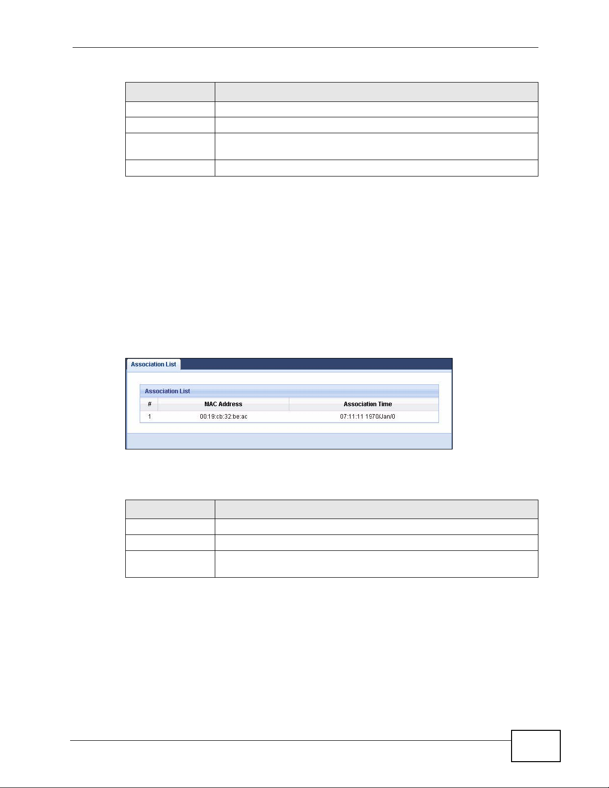
Table 16 Packet Statistics
LABEL DESCRIPTION
Up Time This is the total time the NVG2053 has been for each session.
Poll Interval(s) Enter the time interval in seconds for refreshing statistics in this field.
Set Interval Click this button to apply the new poll interval you entered in the Poll
Interval(s) field.
Stop Click Stop to stop refreshing statistics.
6.6 The WLAN Station Status Screen
Click Monitor > WLAN Station Status or the WLAN Station Status
(Details...) hyperlink in the Status screen. View the wireless stations that are
currently associated to the NVG2053 in the Association List. Association means
that a wireless client (for example, your network or computer with a wireless
network card) has connected successfully to the AP (or wireless router) using the
same SSID, channel and security settings.
Chapter 6 Monitor
Figure 26 Summary: Wireless Association List
The following table describes the labels in this screen.
Table 17 Summary: Wireless Association List
LABEL DESCRIPTION
# This is the index number of an associated wireless station.
MAC Address This field displays the MAC address of an associated wireless station.
Association Time This field displays the time and date a wireless station first associated
with the NVG2053’s WLAN network.
NVG2053 User’s Guide
79

Chapter 6 Monitor
80
NVG2053 User’s Guide

CHAPTER 7
Broadband
7.1 Overview
This chapter discusses the NVG2053’s Broadband screens. Use these screens to
configure your NVG2053 for Internet access.
A WAN (Wide Area Network) connection is an outside connection to another
network or the Internet. It connects your private networks such as a LAN (Local
Area Network) and other networks, so that a computer in one location can
communicate with computers in other locations.
Figure 27 LAN and WAN
LAN
See Section 7.4 on page 90 for advanced technical information on WAN.
7.1.1 What You Can Do in this Chapter
Use the Broadband screen (Section 7.3 on page 83) to view and configure the
WAN settings on the NVG2053 for Internet access.
7.2 What You Need To Know
The information in this section can help you configure the screens for your WAN
connection, as well as enable/disable some advanced features of your NVG2053.
WAN
NVG2053 User’s Guide
81

Chapter 7 Broadband
Encapsulation Method
Encapsulation is used to include data from an upper layer protocol into a lower
layer protocol. To set up a WAN connection to the Internet, you need to use the
same encapsulation method used by your ISP (Internet Service Provider). If your
ISP offers a dial-up Internet connection using PPPoE (PPP over Ethernet), they
should also provide a username and password (and service name) for user
authentication.
WAN IP Address
The WAN IP address is an IP address for the NVG2053, which makes it accessible
from an outside network. It is used by the NVG2053 to communicate with other
devices in other networks. It can be static (fixed) or dynamically assigned by the
ISP each time the NVG2053 tries to access the Internet.
If your ISP assigns you a static WAN IP address, they should also assign you the
subnet mask and DNS server IP address(es) and a gateway IP address.
DNS Server Address Assignment
Use Domain Name System (DNS) to map a domain name to its corresponding IP
address and vice versa, for instance, the IP address of www.zyxel.com is
204.217.0.2. The DNS server is extremely important because without it, you must
know the IP address of a computer before you can access it.
The NVG2053 can get the DNS server addresses in the following ways.
1 The ISP tells you the DNS server addresses, usually in the form of an information
sheet, when you sign up. If your ISP gives you DNS server addresses, manually
enter them in the DNS server fields.
2 If your ISP dynamically assigns the DNS server IP addresses (along with the
NVG2053’s WAN IP address), set the DNS server fields to get the DNS server
address from the ISP.
82
NVG2053 User’s Guide

7.3 The Broadband Screen
Use this screen to change your NVG2053’s Internet access settings. Click
Network > Broadband from the Configuration menu. The summary table
shows you the configured WAN services (connections) on the NVG2053.
Figure 28 Network > Broadband
The following table describes the labels in this screen.
Chapter 7 Broadband
Table 18 Network > Broadband
LABEL DESCRIPTION
Add new WAN
interface
# This is the index number of the connection.
Name This is the service name of the connection.
Mode This shows whether the connection is in routing mode or bridge mode.
Encapsulation This shows the method of encapsulation used by this connection.
8021p This indicates the 802.1P priority level assigned to traffic sent through
VLAN tag This indicates the VLAN ID number assigned to traffic sent through
IGMP Proxy This shows whether the NVG2053 act as an IGMP proxy on this
NAT This shows whether NAT is activated or not for this connection.
Default Gateway This shows whether the NVG2053 use the WAN interface of this
Modify Click the Edit icon to configure the WAN connection.
Click this button to create a new connection.
this connection.
This field is blank when there is no priority level assigned.
this connection.
This field is blank when there is no VLAN ID number assigned.
connection.
connection as the system default gateway.
Apply Click Apply to save your changes back to the NVG2053.
Cancel Click Cancel to return to the previous configuration.
NVG2053 User’s Guide
Click the Delete icon to remove the WAN connection.
83

Chapter 7 Broadband
7.3.1 Broadband Configuration
Click the Edit or Add button in the Broadband screen to configure a WAN
connection. The screen differs according to the mode and encapsulation you
choose.
7.3.1.1 DHCP
This screen displays when you select the Routing mode and DHCP encapsulation.
Figure 29 Network > Broadband: DHCP Encapsulation
84
The following table describes the labels in this screen.
Table 19 Network > Broadband: DHCP Encapsulation
LABEL DESCRIPTION
General
Name Specify a descriptive name of up to 15 alphanumeric characters for this
connection.
NVG2053 User’s Guide

Chapter 7 Broadband
Table 19 Network > Broadband: DHCP Encapsulation
LABEL DESCRIPTION
Mode Select Routing (default) from the drop-down list box if your ISP give
you one IP address only and you want multiple computers to share an
Internet account.
Select Bridge when your ISP provides you more than one IP address
and you want the connected computers to get individual IP address
from ISP’s DHCP server directly. If you select Bridge, you cannot use
routing functions, such as QoS, Firewall, DHCP server and NAT on
traffic from the selected LAN port(s).
Encapsulation You must choose the DHCP (Ethernet) option when the WAN port is
used as a regular Ethernet.
IP Address
Obtain an IP
Address
Automatically
Static IP
Address
IP Address Enter the static IP address provided by your ISP.
IP Subnet
Mask
Gateway IP
Address
Routing Feature
NAT Enable Select this option to activate NAT on this connection.
IGMP Proxy
Enable
A static IP address is a fixed IP that your ISP gives you. A dynamic IP
address is not fixed; the ISP assigns you a different one each time you
connect to the Internet. Select this if you have a dynamic IP address.
Select this option If the ISP assigned a fixed IP address.
Enter the subnet mask provided by your ISP.
Enter the gateway IP address provided by your ISP.
Internet Group Multicast Protocol (IGMP) is a network-layer protocol
used to establish membership in a Multicast group - it is not used to
carry user data.
Apply as Default
Gateway
DNS Server
First DNS Server
Second DNS
Server
Third DNS
Server
VLAN
Select this option to have the NVG2053 act as an IGMP proxy on this
connection. This allows the NVG2053 to get subscribing information
and maintain a joined member list for each multicast group. It can
reduce multicast traffic significantly.
Select this option to have the NVG2053 use the WAN interface of this
connection as the system default gateway.
This field is not configurable when another connection has been set to
be the deafult gateway through which the NVG2053 forwards the
traffic.
Select Obtained From ISP if y our ISP dynamically assigns DNS server
information (and the NVG2053's WAN IP address). The field to the right
displays the (read-only) DNS server IP address that the ISP assigns.
Select UserDefined if you have the IP address of a DNS server. Enter
the DNS server's IP address in the field to the right.
Select None if you do not want to configure DNS servers. If you do not
configure a DNS server, you must know the IP address of a computer in
order to access it.
NVG2053 User’s Guide
85

Chapter 7 Broadband
Table 19 Network > Broadband: DHCP Encapsulation
LABEL DESCRIPTION
VLAN Select Enable to add the VLAN tag (specified below) to the outgoing
802.1p IEEE 802.1p defines up to 8 separate traffic types by inserting a tag
VLAN TAG Type the VLAN ID number (from 1 to 4094) for traffic through this
Back Click Back to return to the previous screen.
Apply Click Apply to save your changes back to the NVG2053.
Cancel Click Cancel to begin configuring this screen afresh.
traffic through this connection. Otherwise, select Disable.
into a MAC-layer frame that contains bits to define class of service.
Type the IEEE 802.1p priority level (from 0 to 7) to add to traffic
through this connection. The greater the number, the higher the
priority level.
This field is configurable when you select Enable in the VLAN field.
connection.
This field is configurable when you select Enable in the VLAN field.
7.3.2 PPPoE Encapsulation
The NVG2053 supports PPPoE (Point -to-Point Protocol over Ethernet). PPPoE is an
IETF standard (RFC 2516) specifying how a personal computer (PC) inter acts with
a broadband modem (DSL, cable, wireless, etc.) connection. The PPPoE option is
for a dial-up connection using PPPoE.
For the service provider, PPPoE offers an access and authentication method that
works with existing access control systems (for example Radius).
One of the benefits of PPPoE is the ability to let you access one of multiple network
services, a function known as dynamic servic e selection. This enables the service
provider to easily create and offer new IP services for individuals.
Operationally, PPP oE save s significant ef fort for both you and the ISP or carrier, as
it requires no specific configuration of the broadband modem at the customer site .
By implementing PPPoE directly on the NVG2053 (rather than individual
computers), the computers on the LAN do not need PPPoE software installed,
since the NVG2053 does that part of the task. Furthermore, with NAT, all of the
LANs’ computers will have access.
86
NVG2053 User’s Guide

Chapter 7 Broadband
This screen displays when you select the Routing mode and PPPoE
encapsulation.
Figure 30 Network > Broadband: PPPoE Encapsulation
The following table describes the labels in this screen.
Table 20 Network > Broadband: PPPoE Encapsulation
LABEL DESCRIPTION
General
Name Specify a descriptive name of up to 15 alphanumeric characters for this
connection.
Mode Select Routing (default) from the drop-down list box if your ISP give
you one IP address only and you want multiple computers to share an
Internet account.
Select Bridge when your ISP provides you more than one IP address
and you want the connected computers to get individual IP address
from ISP’s DHCP server directly. If you select Bridge, you cannot use
routing functions, such as QoS, Firewall, DHCP server and NAT on
traffic from the selected LAN port(s).
Encapsulation Select PPPoE for a dial-up connection.
PPP Information
PPP Username Enter the user name exactly as your ISP assigned. If assigned a name
in the form user@domain where domain identifies a service name, then
enter both components exactly as given.
NVG2053 User’s Guide
87

Chapter 7 Broadband
Table 20 Network > Broadband: PPPoE Encapsulation
LABEL DESCRIPTION
PPP Password Enter the password associated with the user name above.
PPP Auto
Connect
IDLE Timeout This value specifies the time in minutes that elapses before the router
PPPoE Service
Name
Routing Feature
NAT Enable Select this option to activate NAT on this connection.
IGMP Proxy
Enable
Apply as Default
Gateway
Select this option if you do not want the connection to time out.
automatically disconnects from the PPPoE server.
This field is not configurable if you select PPP Auto Connect.
Enter the name of your PPPoE service here.
Internet Group Multicast Protocol (IGMP) is a network-layer protocol
used to establish membership in a Multicast group - it is not used to
carry user data.
Select this option to have the NVG2053 act as an IGMP proxy on this
connection. This allows the NVG2053 to get subscribing information
and maintain a joined member list for each multicast group. It can
reduce multicast traffic significantly.
Select this option to have the NVG2053 use the WAN interface of this
connection as the system default gateway.
This field is not configurable when another connection has been set to
be the deafult gateway through which the NVG2053 forwards the
traffic.
DNS Server
First DNS Server
Second DNS
Server
Third DNS
Server
VLAN
VLAN Select Enable to add the VLAN tag (specified below) to the outgoing
802.1p IEEE 802.1p defines up to 8 separate traffic types by inserting a tag
VLAN TAG Type the VLAN ID number (from 1 to 4094) for traffic through this
Select Obtained From ISP if y our ISP dynamically assigns DNS server
information (and the NVG2053's WAN IP address). The field to the right
displays the (read-only) DNS server IP address that the ISP assigns.
Select UserDefined if you have the IP address of a DNS server. Enter
the DNS server's IP address in the field to the right.
Select None if you do not want to configure DNS servers. If you do not
configure a DNS server, you must know the IP address of a computer in
order to access it.
traffic through this connection. Otherwise, select Disable.
into a MAC-layer frame that contains bits to define class of service.
Type the IEEE 802.1p priority level (from 0 to 7) to add to traffic
through this connection. The greater the number, the higher the
priority level.
This field is configurable when you select Enable in the VLAN field.
connection.
88
This field is configurable when you select Enable in the VLAN field.
NVG2053 User’s Guide

Table 20 Network > Broadband: PPPoE Encapsulation
LABEL DESCRIPTION
Back Click Back to return to the previous screen.
Apply Click Apply to save your changes back to the NVG2053.
Cancel Click Cancel to begin configuring this screen afresh.
7.3.2.1 Bridge
This screen displays when you select the Bridge mode.
Figure 31 Network > Broadband: Bridge mode
Chapter 7 Broadband
The following table describes the labels in this screen.
Table 21 Network > Broadband: Bridge mode
LABEL DESCRIPTION
General
Name Specify a descriptive name of up to 15 alphanumeric characters for this
connection.
Mode Select Routing (default) from the drop-down list box if your ISP give
you one IP address only and you want multiple computers to share an
Internet account.
Select Bridge when your ISP provides you more than one IP address
and you want the connected computers to get individual IP address
from ISP’s DHCP server directly. If you select Bridge, you cannot use
routing functions, such as QoS, Firewall, DHCP server and NAT on
traffic from the selected LAN port(s).
Bridged VLAN Select the LAN port(s) from which traffic will be forwarded to the WAN
interface directly.
You cannot configure a QoS class for traffic from the LAN port which is
selected here.
VLAN
NVG2053 User’s Guide
89

Chapter 7 Broadband
Table 21 Network > Broadband: Bridge mode
LABEL DESCRIPTION
VLAN Select Enable to add the VLAN tag (specified below) to the outgoing
802.1p IEEE 802.1p defines up to 8 separate traffic types by inserting a tag
VLAN TAG Type the VLAN ID number (from 1 to 4094) for traffic through this
Back Click Back to return to the previous screen.
Apply Click Apply to save your changes back to the NVG2053.
Cancel Click Cancel to begin configuring this screen afresh.
traffic through this connection. Otherwise, select Disable.
into a MAC-layer frame that contains bits to define class of service.
Type the IEEE 802.1p priority level (from 0 to 7) to add to traffic
through this connection. The greater the number, the higher the
priority level.
This field is configurable when you select Enable in the VLAN field.
connection.
This field is configurable when you select Enable in the VLAN field.
7.4 Technical Reference
The following section contains additional technical information about the NVG2053
features described in this chapter.
Introduction to VLANs
A Virtual Local Area Network (VLAN) allows a physical network to be partitioned
into multiple logical networks. Devices on a logical network belong to one group. A
device can belong to more than one group. With VLAN, a device cannot directly
talk to or hear from devices that are not in the same group(s); the traffic must
first go through a router.
In Multi-Tenant Unit (MTU) applications, VLAN is vital in providing isolation and
security among the subscribers. When properly configured, VLAN prevents one
subscriber from accessing the netw ork resources of another on the same LAN,
thus a user will not see the printers and hard disks of another user in the same
building.
VLAN also increases network performance by limiting broadcasts to a smaller and
more manageable logical broadcast domain. In traditional switched environments,
all broadcast packets go to each and every individual port. Wit h VLAN, all
broadcasts are confined to a specific broadcast domain.
90
NVG2053 User’s Guide

Chapter 7 Broadband
Introduction to IEEE 802.1Q Tagged VLAN
A tagged VLAN uses an explicit tag (VLAN ID) in the MAC header to identify the
VLAN membership of a frame across bridges - they are not confined to the switch
on which they were created. The VLANs can be created statically by hand or
dynamically through GVRP. The VLAN ID associates a frame with a specific VLAN
and provides the information that switches need to process the frame across the
network. A tagged frame is four bytes longer than an untagged frame and
contains two bytes of TPID (Tag Protocol Identi f ier), residing within the type/
length field of the Ethernet frame) and two bytes of TCI (Tag Control Information),
starts after the source address field of the Ethernet frame).
The CFI (Canonical Format Indicator) is a single-bit flag, always set to zero for
Ethernet switches. If a frame received at an Ethernet port has a CFI set to 1, then
that frame should not be forwarded as it is to an untagged port. The remaining
twelve bits define the VLAN ID, giving a possible maximum number of 4,096
VLANs. Note that user priority and VLAN ID are independent of each other. A
frame with VID (VLAN Identifier) of null (0) is called a pr iority frame, meaning that
only the priority level is significant and the default VID of the ingress port is given
as the VID of the frame. Of the 4096 possible VIDs, a VID of 0 is used to identify
priority frames and value 4095 (FFF) is reserved, so the maximum possible VLAN
configurations are 4,094.
TPID
2 Bytes
User Priority
3 Bits
CFI
1 Bit
VLAN ID
12 Bits
Multicast
IP packets are transmitted in either one of two ways - Unicas t ( 1 sen der - 1
recipient) or Broadcast (1 sender - everybody on the network). Multicast delivers
IP packets to a group of hosts on the network - not everybody and not just 1.
Internet Group Multicast Protocol (IGMP) is a network-layer protocol used to
establish membership in a Multicast group - it is not used to carry user data. IGMP
version 2 (RFC 2236) is an improvement over version 1 (RFC 1112) but IGMP
version 1 is still in wide use. If you would like to read more detailed information
about interoperability between IGMP version 2 and version 1, please see sections
4 and 5 of RFC 2236. The class D IP address is used to identify host groups and
can be in the range 224.0.0.0 to 239.255.255.255. The address 224.0.0.0 is not
assigned to any group and is used by IP multicast computers. The address
224.0.0.1 is used for query messages and is assigned to the permanent group of
all IP hosts (including gateways). All host s must join t he 224.0.0.1 group in order
to participate in IGMP. The address 224.0.0.2 is assigned to the multicast routers
group.
NVG2053 User’s Guide
91

Chapter 7 Broadband
At start up, the NVG2053 queries all directly connected networks to gather group
membership. After that, the NVG2053 periodically updates this information.
92
NVG2053 User’s Guide

CHAPTER 8
Wireless LAN
8.1 Overview
This chapter discusses how to configure the wireless network settings in your
NVG2053.
The following figure provides an example of a wireless network.
Figure 32 Example of a Wireless Network
The wireless network is the part in the blue circle. In this wireless network,
devices A and B are called wireless clients. The wireless clients use the access
point (AP) to interact with other devices (such as the printer) or with the Internet.
Your NVG2053 is the AP.
See Chapter 2 on page 33 for a tutorial showing how to set up your wireless
connection in an example scenario.
NVG2053 User’s Guide
A
B
93

Chapter 8 Wireless LAN
See Section 8.10 on page 111 and Appendix C on page 275 for advanced technical
information on wireless networks.
8.1.1 What You Can Do in this Chapter
•Use the General screen (Section 8.3 on page 97) to enable the Wireless LAN,
enter the SSID and select the wireless security mode.
•Use the MAC Filter screen (Section 8.4 on page 104) to allow or deny wireless
clients based on their MAC addresses from connecting to the NVG2053.
•Use the Advanced screen (Section 8.5 on page 105) to allow wireless advanced
features, such as intra-BSS networking and set the RTS/CTS Threshold.
•Use the QoS screen (Section 8.6 on page 107) to have the NVG2053
automatically set priority levels to services, such as e-mail, VoIP, chat, and so
on.
•The WPS screen and the WPS Station screen let you use WiFi Protected Setup
(WPS) to quickly set up a wireless network with strong security, without having
to configure security settings manually.
Use the WPS screen (Section 8.7 on page 107) to enable or disable WPS,
generate a security PIN (Personal Identification Number) and see information
about the NVG2053’s WPS status.
Use the WPS Station (Section 8.8 on page 109) screen to add a wireless client
by pressing a button or using a PIN.
•Use the Scheduling screen (Section 8.9 on page 110) to set the time s your
wireless LAN is turned on and off.
8.2 What You Need to Know
Every wireless network must follow these basic guidelines.
• Every wireless client in the same wireless network must use the same SSID.
The SSID is the name of the wireless network. It stands for Service Set IDentity.
• If two wireless networks overlap, they should use different channels.
Like radio stations or television channels, each wireless network uses a specific
channel, or frequency, to send and receive information.
• Every wireless client in the same wireless network must use securit y compatible
with the AP.
Security stops unauthorized devices from using the wireless net work. It can also
protect the information that is sent in the wireless network.
94
Wireless Basics
“Wireless” is essentially radio communication. In the same way that walkie-talkie
radios send and receive information over the airwaves, wireless networking
NVG2053 User’s Guide

Chapter 8 Wireless LAN
devices exchange information with one another. A wireless networking device is
just like a radio that lets your computer exchange information with radios
attached to other computers. Like walkie-talkies, most wireless networking
devices operate at radio frequency bands that are open to the public and do not
require a license to use. However, wireless networking is different from that of
most traditional radio communications in that there a number of wireless
networking standards available with different methods of data encryption.
Wireless Network Construction
Wireless networks consist of wireless clients, access points and bridges.
• A wireless client is a radio connected to a user’s computer.
• An access point is a radio with a wired connection to a network, which can
connect with numerous wireless clients and let them access the network.
• A bridge is a radio that relays communications between access points and
wireless clients, extending a network’s range.
Traditionally, a wireless network operates in one of two ways.
• An “infrastructure” type of network has one or more access points and one or
more wireless clients. The wireless clients connect to the access points.
• An “ad-hoc” type of network is one in which there is no access point. Wireless
clients connect to one another in order to exchange information.
Network Names
Each network must have a name, referred to as the SSID - “Service Set
IDentifier”. The “service set” is the network, so the “service set identifier” is the
network’s name. This helps you identify your wireless network when wireless
networks’ coverage areas overlap and you have a variety of networks to choose
from.
Radio Channels
In the radio spectrum, there are certain frequency bands allocated for unlicensed,
civilian use. For the purposes of wireless networking, t hese bands are divided into
numerous channels. This allows a variety of networks to exist in the same place
without interfering with one another. When you create a network, you must select
a channel to use.
Since the available unlicensed spectrum varies from one country to another, the
number of available channels also varies.
NVG2053 User’s Guide
95

Chapter 8 Wireless LAN
Wireless Security
By their nature, radio communications are simple to intercept. For wireless data
networks, this means that anyone within range of a wireless network without
security can not only read the data passing over the airwaves, but also join the
network. Once an unauthorized person has access to the network she/he can
either steal information or introduce malware (malicious software) intended to
compromise the network. For these reasons, a variety of security systems have
been developed to ensure that only authorized people can use a wireless data
network, or understand the data carried on it.
These security standards do two things. First, they authenticate. This means that
only people presenting the right credentials (often a username and password, or a
“key” phrase) can access the network. Second, they encrypt. This means that the
information sent over the air is encoded. Only people with the code key can
understand the information, and only people who have been authenticated are
given the code key.
These security standards vary in effectiveness. Some can be broken, such as the
old Wired Equivalent Protocol (WEP). Using WEP is better than using no security at
all, but it will not keep a determined attacker out. Other security standards are
secure in themselves but can be broken if a user does not use them properly. For
example, the WPA-PSK security standard is perfectly secure if you use a long key
which is difficult for an attacker’s softw are to gues s - f or example, a twenty-letter
long string of apparently random numbers and letters - but it is not very secure if
you use a short key which is very easy to guess.
Because of the damage that can be done by a malicious attacker, it’s not just
people who have sensitive information on their network who should use security.
Everybody who uses any wireless network should ensure that effective security is
in place.
A good way to come up with effective security keys , passwords and so on is to use
obscure information that you personally will easily remember, and to enter it in a
way that appears random and does not include real words. For example, if your
mother owns a 1970 Dodge Challenger and her favorite movie is Vanishing Point
(which you know was made in 1971) you could use “70dodchal71vanpoi” as your
security key.
Signal Problems
Because wireless networks are radio networks, their signals are subject to
limitations of distance, interference and absorption.
Problems with distance occur when the two radios are too far apart. Problems with
interference occur when other radio waves interrupt the data signal. Interference
may come from other radio transmissions, such as military or air traffic control
96
NVG2053 User’s Guide

communications, or from machines that are coincidental emitters such as electric
motors or microwaves. Problems with absorption occur when physical objects
(such as thick walls) are between the two radios, muffling the signal.
8.3 General Wireless LAN Screen
Use this screen to enable the Wireless LAN, enter the SSID and select the wireless
security mode.
Note: If you are configuring the NVG2053 from a computer connected to the wireless
LAN and you change the NVG2053’s SSID, channel or security settings, you
will lose your wireless connection when you press Apply to confirm. You must
then change the wireless settings of your computer to match the NVG2053’s
new settings.
Click Network > Wireless LAN to open the General screen.
Chapter 8 Wireless LAN
Figure 33 Network > Wireless LAN > General
The following table describes the general wireless LAN labels in this screen.
Table 22 Network > Wireless LAN > General
LABEL DESCRIPTION
Wireless Setup
Wireless LAN This is turned on by default.
Name(SSID) The SSID (Service Set IDentity) identifies the service set with which a
NVG2053 User’s Guide
You can turn the wireless LAN on or off using the switch at the rear panel
of the NVG2053. The current wireless state is reflected in this field.
wireless device is associated. Wireless devices associating to the access
point (AP) must have the same SSID. Enter a descriptive name (up to 32
English keyboard characters) for the wireless LAN.
97

Chapter 8 Wireless LAN
Table 22 Network > Wireless LAN > General
LABEL DESCRIPTION
Hide SSID Select this check box to hide the SSID in the outgoing beacon frame so a
Channel
Selection
Auto Channel
Selection
Operating
Channel
Security
Security
Mode
station cannot obtain the SSID through scanning using a site survey tool.
Select a channel from the drop-down list box. The options vary depending
on the frequency band and the country you are in. If you are having
problems with wireless interference, changing the channel may help. Try
to use a channel that is as many channels away from any channels used
by neighboring APs as possible.
This option is only available if Auto Channel Selection is disabled.
Select this option to have the NVG2053 automatically determine a channel
to use.
This displays the channel the NVG2053 is currently using.
Select Static WEP, WPA-PSK, WPA, WPA2-PSK or WPA2 to add
security on this wireless network. The wireless clients which want to
associate to this network must have same wireless security settings as the
NVG2053. After you select to use a security, additional options appears in
this screen.
Apply Click Apply to save your changes back to the NVG2053.
Cancel Click Cancel to reload the previous configuration for this screen.
8.3.1 No Security
Select No Security to allow wireless stations to communicate with the access
points without any data encryption or authentication.
Or you can select No Security to allow any client to associate this
network without any data encryption or authentication.
See the following sections for more details about this field.
98
NVG2053 User’s Guide

Chapter 8 Wireless LAN
Note: If you do not enable any wireless security on your NVG2053, your network is
accessible to any wireless networking device that is within range.
Figure 34 Network > Wireless LAN > General: No Security
The following table describes the labels in this screen.
Table 23 Network > Wireless LAN > General: No Security
LABEL DESCRIPTION
Security
Mode
Choose No Security from the drop-down list box.
8.3.2 WEP Encryption
Your NVG2053 allows you to configure up to four 64-bit or 128-bit WEP keys but
only one key can be enabled at any one time.
NVG2053 User’s Guide
99

Chapter 8 Wireless LAN
In order to configure and enable WEP encryption, click Network > Wireless LAN
to display the General screen. Select Static WEP from the Security Mode list.
Figure 35 Network > Wireless LAN > General: Static WEP
100
The following table describes the wireless LAN security labels in this screen.
Table 24 Network > Wireless LAN > General: Static WEP
LABEL DESCRIPTION
Security
Mode
PassPhrase Enter a Passphrase (up to 26 printable characters) and click Generate.
WEP
Encryption
Select Static WEP to enable data encryption.
A passphrase functions like a password. In WEP security mode, it is further
converted by the NVG2053 into a complicated string that is referred to as
the “key”. This key is requested from all devices wishing to connect to a
wireless network.
Select 64-bits or 128-bits.
This dictates the length of the security key that the network is going to
use.
NVG2053 User’s Guide
 Loading...