

Page 1

NBG-510S
802.11g Wireless Remote Access Broadband Gateway
User’s Guide
Version 1.00
7/2007
Edition 1
DEFAULT LOGIN
IP Address http://192.168.1.1
User Name admin
Password 1234
www.zyxel.com
Page 2

Page 3

About This Guide
About This Guide
Intended Audience
This manual is intended for home and small business network administrators who want to
install and configure the ZyXEL Device. This guide assumes that the administrators who are
familiar with basic network configuration.
Related Documentation
• Quick Start Guide
The Quick Start Guide is designed to help you get up and running right away. It contains
information on setting up your network and configuring for initial secure remote access to
the LAN.
• Web Configurator Online Help
Embedded web help for descriptions of individual screens and supplementary
information.
• Supporting Disk
Refer to the included CD for support documents.
• ZyXEL Web Site
Please refer to www.zyxel.com
certifications.
for additional support documentation and product
User Guide Feedback
Help us help you. Send all User’s Guide-related comments, questions or suggestions for
improvement to the following address, or use e-mail instead. Thank you!
The Technical Writing Team,
ZyXEL Communications Corp.,
6 Innovation Road II,
Science-Based Industrial Park,
Hsinchu, 300, Taiwan.
E-mail: techwriters@zyxel.com.tw
NBG-510S User’s Guide
3
Page 4

Document Conventions
Document Conventions
Warnings and Notes
These are how warnings and notes are shown in this User’s Guide.
1 Warnings tell you about things that could harm you or your device.
" Notes tell you other important information (for example, other things you may
need to configure or helpful tips) or recommendations.
Syntax Conventions
• The NBG-510S may be referred to as the “ZyXEL Device”, the “device” or the “system”
in this User’s Guide.
• Product labels, screen names, field labels and field choices are all in bold font.
• A key stroke is denoted by square brackets and uppercase text, for example, [ENTER]
means the “enter” or “return” key on your keyboard.
• “Enter” means for you to type one or more characters and then press the [ENTER] key.
“Select” or “choose” means for you to use one of the predefined choices.
• A right angle bracket ( > ) within a screen name denotes a mouse click. For example,
Network > WAN > Internet Connection means you first click Network in the
navigation panel, then the WAN sub menu and finally the Internet Connection tab to get
to that screen.
• Units of measurement may denote the “metric” value or the “scientific” value. For
example, “k” for kilo may denote “1000” or “1024”, “M” for mega may denote “1000000”
or “1048576” and so on.
• “e.g.,” is a shorthand for “for instance”, and “i.e.,” means “that is” or “in other words”.
4
NBG-510S User’s Guide
Page 5

Document Conventions
Icons Used in Figures
Figures in this User’s Guide may use the following generic icons. The ZyXEL Device icon is
not an exact representation of your device.
ZyXEL Device Computer Notebook computer
Server DSLAM Firewall
Telephone Switch Router
Broadband modem or
router
NBG-510S User’s Guide
5
Page 6

Safety Warnings
Safety Warnings
1 For your safety, be sure to read and follow all warning notices and instructions.
• Do NOT use this product near water, for example, in a wet basement or near a swimming
pool.
• Do NOT expose your device to dampness, dust or corrosive liquids.
• Do NOT store things on the device.
• Do NOT install, use, or service this device during a thunderstorm. There is a remote risk
of electric shock from lightning.
• Connect ONLY suitable accessories to the device.
• Do NOT open the device or unit. Opening or removing covers can expose you to
dangerous high voltage points or other risks. ONLY qualified service personnel should
service or disassemble this device. Please contact your vendor for further information.
• Make sure to connect the cables to the correct ports.
• Place connecting cables carefully so that no one will step on them or stumble over them.
• Always disconnect all cables from this device before servicing or disassembling.
• Use ONLY an appropriate power adaptor or cord for your device.
• Connect the power adaptor or cord to the right supply voltage (for example, 110V AC in
North America or 230V AC in Europe).
• Do NOT allow anything to rest on the power adaptor or cord and do NOT place the
product where anyone can walk on the power adaptor or cord.
• Do NOT use the device if the power adaptor or cord is damaged as it might cause
electrocution.
• If the power adaptor or cord is damaged, remove it from the power outlet.
• Do NOT attempt to repair the power adaptor or cord. Contact your local vendor to order a
new one.
• Do NOT remove the plug and plug into a wall outlet by itself; always attach the plug to the
power supply first before insert into the wall
• Do not use the device outside, and make sure all the connections are indoors. There is a
remote risk of electric shock from lightning.
• Do NOT obstruct the device ventilation slots, as insufficient airflow may harm your
device.
• If you wall mount your device, make sure that no electrical lines, gas or water pipes will
be damaged.
6
NBG-510S User’s Guide
Page 7
This product is recyclable. Dispose of it properly.
Safety Warnings
NBG-510S User’s Guide
7
Page 8

Safety Warnings
8
NBG-510S User’s Guide
Page 9

Contents Overview
Contents Overview
Introduction ............................................................................................................................ 25
Introducing the ZyXEL Device ...................................................................................................27
Hardware Connection ................................................................................................................ 29
The Web Configurator ............................................................................................................... 31
Status ......................................................................................................................................... 39
Setup Wizard ............................................................................................................................. 41
Tutorials ..................................................................................................................................... 45
Network ................................................................................................................................... 59
Wireless LAN ............................................................................................................................. 61
WAN ......................................................................................................................................... 69
LAN ............................................................................................................................................ 77
DHCP ........................................................................................................................................ 79
NAT and Firewall (WAN to LAN) ................................................................................................ 81
DDNS ........................................................................................................................................ 89
Security ...................................................................................................................................91
Access Control .......................................................................................................................... 93
Content Filtering ...................................................................................................................... 101
Management ......................................................................................................................... 103
UPnP ....................................................................................................................................... 105
Static Route ..............................................................................................................................113
Maintenance ......................................................................................................................... 117
System ......................................................................................................................................119
Logs ......................................................................................................................................... 123
Tools ........................................................................................................................................ 125
Secure Remote Access (User Portal) .................................................................................133
Secure Remote Access Title .................................................................................................. 135
Secure Remote Access User Info ........................................................................................... 137
Manage Accessible LAN Resources ....................................................................................... 141
Manage User Access Permissions .......................................................................................... 143
Secure Remote Desktop Control ............................................................................................. 151
Secure Remote Access Screens ............................................................................................. 155
NBG-510S User’s Guide
9
Page 10

Contents Overview
Troubleshooting and Appendices ......................................................................................163
Troubleshooting ....................................................................................................................... 165
10
NBG-510S User’s Guide
Page 11

Table of Contents
Table of Contents
About This Guide ...................................................................................................................... 3
Document Conventions............................................................................................................4
Safety Warnings........................................................................................................................6
Contents Overview ...................................................................................................................9
Table of Contents.................................................................................................................... 11
List of Figures ......................................................................................................................... 19
List of Tables...........................................................................................................................23
Part I: Introduction................................................................................. 25
Chapter 1
Introducing the ZyXEL Device...............................................................................................27
1.1 Overview .............................................................................................................................. 27
1.1.1 Remote User Access Secured by SSL ...................................................................... 27
1.2 Good Habits for Managing the ZyXEL Device ..................................................................... 28
Chapter 2
Hardware Connection.............................................................................................................29
2.1 Ports and Connectors .......................................................................................................... 29
2.2 LEDs .................................................................................................................................... 30
Chapter 3
The Web Configurator ............................................................................................................31
3.1 Web Configurator Overview ................................................................................................. 31
3.2 Logging into the ZyXEL Device .......................................................................................... 31
3.3 Web Configurator Main Screen ........................................................................................... 34
3.3.1 Title Bar ...................................................................................................................... 35
3.3.2 Navigation Panel ........................................................................................................ 35
3.3.3 Main Window ..............................................................................................................36
3.3.4 Status Bar ................................................................................................................... 36
3.4 Login Timeout ...................................................................................................................... 37
3.4.1 Changing Login Timeout ............................................................................................ 37
3.5 Changing Password ............................................................................................................ 37
NBG-510S User’s Guide
11
Page 12

Table of Contents
3.6 Device Reset ....................................................................................................................... 38
Chapter 4
Status.......................................................................................................................................39
4.1 Status Screen ..................................................................................................................... 39
Chapter 5
Setup Wizard ...........................................................................................................................41
5.1 Wizard Setup Overview ....................................................................................................... 41
Chapter 6
Tutorials ................................................................................................................................... 45
6.1 Secure Remote Access Configuration Overview ................................................................. 45
6.1.1 Configure Secure Remote Access ............................................................................. 45
6.1.2 Test Secure Remote Access ...................................................................................... 45
6.2 Secure Remote Desktop Connections ................................................................................ 45
6.2.1 Configure the Computer to be Managed .................................................................... 46
6.2.2 Configure the ZyXEL Device ...................................................................................... 47
6.2.3 Use the Secure Remote Desktop Connection ........................................................... 48
6.3 Wireless Tutorial .................................................................................................................. 50
6.4 Example Parameters ........................................................................................................... 51
6.5 Configuring the ZyXEL Device ............................................................................................ 51
6.6 Configuring the Wireless Client ........................................................................................... 52
6.6.1 Connecting to a Wireless LAN ................................................................................... 52
6.6.2 Creating and Using a Profile ...................................................................................... 54
Part II: Network....................................................................................... 59
Chapter 7
Wireless LAN...........................................................................................................................61
7.1 Wireless Network Overview ................................................................................................. 61
7.2 Wireless Security Overview .................................................................................................62
7.2.1 SSID ........................................................................................................................... 62
7.2.2 User Authentication .................................................................................................... 63
7.2.3 Encryption .................................................................................................................. 63
7.3 Wireless LAN Screen ..................................................................................................... 63
7.3.1 No Security ................................................................................................................. 64
7.3.2 WEP Encryption ......................................................................................................... 65
7.3.3 WPA-PSK/WPA2-PSK ................................................................................................ 66
7.3.4 WPA/WPA2 ................................................................................................................ 67
12
NBG-510S User’s Guide
Page 13

Table of Contents
Chapter 8
WAN ......................................................................................................................................... 69
8.1 WAN IP Address Assignment .............................................................................................. 69
8.2 DNS Server Addresses ......................................................................................................69
8.3 WAN MAC Address ............................................................................................................. 69
8.4 WAN DHCP Client Encapsulation ....................................................................................... 69
8.5 WAN Static IP Encapsulation ............................................................................................... 70
8.6 WAN PPPoE Encapsulation ............................................................................................... 72
8.7 WAN PPTP Encapsulation ................................................................................................. 73
8.8 WAN Multicast .................................................................................................................... 74
Chapter 9
LAN........................................................................................................................................... 77
9.1 LAN Overview ...................................................................................................................... 77
9.1.1 Factory LAN Defaults ................................................................................................. 77
9.2 LAN Screen ......................................................................................................................... 77
Chapter 10
DHCP........................................................................................................................................79
10.1 DHCP ................................................................................................................................ 79
10.1.1 Factory DHCP Defaults ............................................................................................ 79
10.2 DHCP Screen .................................................................................................................... 79
10.2.1 DHCP Client List Screen ....................................................................................... 80
Chapter 11
NAT and Firewall (WAN to LAN) ............................................................................................81
11.1 NAT Overview ................................................................................................................. 81
11.2 Port Forwarding and Firewall ............................................................................................. 81
11.2.1 Configuring Servers Behind Port Forwarding Example ............................................ 82
11.3 Port Forwarding Screen ................................................................................................... 82
11.4 Port Forwarding Add/Edit Screen ...................................................................................... 83
11.5 Trigger Port Forwarding .................................................................................................... 85
11.5.1 Trigger Port Forwarding Example ............................................................................. 85
11.5.2 Two Points To Remember About Trigger Ports ........................................................ 85
11.6 Port Triggering Screen ....................................................................................................... 86
11.7 Port Triggering Add/Edit Screen ........................................................................................ 86
Chapter 12
DDNS........................................................................................................................................89
12.1 Dynamic DNS .................................................................................................................. 89
12.2 DDNS Screen .................................................................................................................... 89
12.3 DDNS Add/Edit Screen ..................................................................................................... 90
NBG-510S User’s Guide
13
Page 14

Table of Contents
Part III: Security...................................................................................... 91
Chapter 13
Access Control........................................................................................................................ 93
13.1 Access Control Introduction ...............................................................................................93
13.2 Quality of Service (QoS) .................................................................................................... 93
13.3 Firewall Overview .............................................................................................................. 94
13.4 Access Control Screen ................................................................................................... 94
13.5 Access Control Add/Edit Screen .................................................................................... 96
13.6 Schedules Screen .......................................................................................................... 98
13.7 Schedules Add/Edit Screen ............................................................................................ 98
13.7.1 Time Period Examples ............................................................................................. 99
Chapter 14
Content Filtering ................................................................................................................... 101
14.1 Content Filter Screen ....................................................................................................... 101
Part IV: Management............................................................................ 103
Chapter 15
UPnP ...................................................................................................................................... 105
15.1 Universal Plug and Play Overview ................................................................................ 105
15.1.1 How Do I Know If I'm Using UPnP? ....................................................................... 105
15.1.2 NAT Traversal ........................................................................................................ 105
15.1.3 Cautions with UPnP ............................................................................................... 105
15.1.4 UPnP and ZyXEL ................................................................................................... 106
15.2 Configuring UPnP ............................................................................................................ 106
15.3 Installing UPnP in Windows Example .............................................................................. 106
15.3.1 Installing UPnP in Windows Me ............................................................................. 107
15.3.2 Installing UPnP in Windows XP ............................................................................. 108
15.4 Using UPnP in Windows XP Example ............................................................................. 108
15.4.1 Auto-discover Your UPnP-enabled Network Device .............................................. 109
15.4.2 Web Configurator Easy Access ..............................................................................110
Chapter 16
Static Route ........................................................................................................................... 113
14
16.1 IP Static Route ...............................................................................................................113
16.2 IP Static Route Screen .....................................................................................................113
16.2.1 IP Static Route Edit ...............................................................................................114
NBG-510S User’s Guide
Page 15

Table of Contents
Part V: Maintenance..............................................................................117
Chapter 17
System ................................................................................................................................... 119
17.1 System Overview ..............................................................................................................119
17.2 System General Screen .................................................................................................119
17.3 Time Setting Screen ........................................................................................................ 120
Chapter 18
Logs ....................................................................................................................................... 123
18.1 Logs Screen ................................................................................................................... 123
Chapter 19
Tools....................................................................................................................................... 125
19.1 Firmware Upload Screen ................................................................................................. 125
19.1.1 Upgrading Firmware ............................................................................................... 126
19.2 Configuration Screen ....................................................................................................... 126
19.2.1 Backup Configuration ............................................................................................. 127
19.2.2 Restore Configuration ............................................................................................ 127
19.2.3 Device Reset .......................................................................................................... 128
19.3 Restart Screen ................................................................................................................. 129
19.4 Box Access Screen .........................................................................................................129
19.5 Diagnostic Tools Screen .................................................................................................. 130
19.5.1 Diagnostic Tools Ping Results ................................................................................ 131
19.5.2 Diagnostic Tools Trace Route Results ................................................................... 131
19.5.3 Diagnostic Tools DNS Resolve Results ................................................................. 132
Part VI: Secure Remote Access (User Portal) ................................... 133
Chapter 20
Secure Remote Access Title............................................................................................... 135
20.1 Configuring the Secure Remote Access Title ................................................................. 135
Chapter 21
Secure Remote Access User Info........................................................................................137
21.1 Overview .......................................................................................................................... 137
21.2 User Info Screen .............................................................................................................. 137
21.2.1 Add/Edit User Info Screen ..................................................................................... 137
21.3 Copy User Views Screen ................................................................................................. 138
NBG-510S User’s Guide
15
Page 16

Table of Contents
Chapter 22
Manage Accessible LAN Resources...................................................................................141
22.1 Manage Servers Overview .............................................................................................. 141
22.2 Manage Servers Screen .................................................................................................. 141
22.2.1 Add/Edit Server Screen ......................................................................................... 142
Chapter 23
Manage User Access Permissions......................................................................................143
23.1 Manage Views Overview ................................................................................................. 143
23.2 Manage Views Screen ..................................................................................................... 143
23.3 Manage a User’s View .................................................................................................... 144
23.4 Add a Category ............................................................................................................... 144
23.5 Adding a Reference ........................................................................................................ 145
23.5.1 Adding a Reference: Manually .............................................................................. 146
23.5.2 Adding a Reference: File Server Login ................................................................. 146
23.5.3 Adding a Reference: Browsing the Shared Folders .............................................. 147
23.5.4 Adding a Reference: Browsing the Shared Folder Contents ................................ 148
Chapter 24
Secure Remote Desktop Control......................................................................................... 151
24.1 Desktop Links Overview .................................................................................................. 151
24.2 Desktop Links Screen ......................................................................................................151
24.3 Manage a User’s Desktop Links View ............................................................................ 152
24.4 Add Desktop Link Screen ............................................................................................... 153
Chapter 25
Secure Remote Access Screens ......................................................................................... 155
25.1 Secure Remote Access Screens ..................................................................................... 155
25.1.1 System Requirements ............................................................................................ 155
25.2 Logging into the Secure Remote Access Screens .......................................................... 155
25.2.1 Logging into the Secure Remote Access Screens Example ................................. 155
25.3 Secure Remote Access Screens Overview .................................................................... 157
25.4 Secure Remote Access Sharing Screen ......................................................................... 158
25.5 Secure Remote Access File Browsing ........................................................................... 158
25.6 File Uploading ................................................................................................................. 159
25.7 Desktop Screen ............................................................................................................... 160
25.8 Desktop Links ................................................................................................................. 160
Part VII: Troubleshooting and Appendices ....................................... 163
Chapter 26
Troubleshooting....................................................................................................................165
16
NBG-510S User’s Guide
Page 17

Table of Contents
26.1 Power, Hardware Connections, and LEDs ...................................................................... 165
26.2 ZyXEL Device Access and Login .................................................................................... 166
26.3 Internet Access ................................................................................................................ 167
26.4 Reset the ZyXEL Device to Its Factory Defaults .............................................................. 168
Appendix A Product Specifications.......................................................................................171
Appendix B Common Services.............................................................................................177
Appendix C Wireless LANs ..................................................................................................181
Appendix D Legal Information ..............................................................................................195
Appendix E Customer Support .............................................................................................199
Index....................................................................................................................................... 205
NBG-510S User’s Guide
17
Page 18

Table of Contents
18
NBG-510S User’s Guide
Page 19

List of Figures
List of Figures
Figure 1 Secure Wired and Wireless Internet Access Through Broadband Modem or Router ............ 27
Figure 2 SSL-protected File Sharing for Remote Users ....................................................................... 28
Figure 3 Rear Panel .............................................................................................................................. 29
Figure 4 LEDs ........................................................................................................................................ 30
Figure 5 Login: Security Message ......................................................................................................... 32
Figure 6 Login: Enter Account Information ............................................................................................ 32
Figure 7 Login: Initial Screen ................................................................................................................ 33
Figure 8 Login: Admin Already Logged In ............................................................................................. 33
Figure 9 Login Screen: Security Message for Administrator Login ....................................................... 34
Figure 10 Main Screen ........................................................................................................................ 34
Figure 11 Timeout Message .................................................................................................................. 37
Figure 12 Maintenance: Password ........................................................................................................ 37
Figure 13 Status .................................................................................................................................... 39
Figure 14 Wizard Welcome Screen ....................................................................................................... 41
Figure 15 Wizard: Administration Settings ............................................................................................ 41
Figure 16 Wizard: Date and Time Settings ............................................................................................. 42
Figure 17 Wizard: MAC Cloning ............................................................................................................ 42
Figure 18 Wizard: Internet Access ......................................................................................................... 43
Figure 19 Wizard: Applying Internet Settings ......................................................................................... 43
Figure 20 Wizard: Applying Internet Settings ......................................................................................... 44
Figure 21 My Computer .......................................................................................................................... 46
Figure 22 My Computer > Properties > Remote ..................................................................................... 46
Figure 23 User Portal > Desktop Links .................................................................................................. 47
Figure 24 User Portal > Desktop Links > Manage View ....................................................................... 47
Figure 25 User Portal > Desktop Links > Manage View > Add ............................................................ 47
Figure 26 Secure Remote Access Login ................................................................................................ 48
Figure 27 Desktop ................................................................................................................................. 49
Figure 28 Desktop Links ........................................................................................................................ 49
Figure 29 Start > Programs > Accessories > Remote Desktop Connection .......................................... 50
Figure 30 Entering the IP Address and Port Number ............................................................................ 50
Figure 31 Network > Wireless LAN ........................................................................................................ 51
Figure 32 Status: Wireless Settings Example ......................................................................................... 52
Figure 33 ZyXEL Utility: Security Settings ............................................................................................. 53
Figure 34 ZyXEL Utility: Confirm Save ................................................................................................... 54
Figure 35 ZyXEL Utility: Link Info .......................................................................................................... 54
Figure 36 ZyXEL Utility: Profile ............................................................................................................... 55
Figure 37 ZyXEL Utility: Add New Profile ............................................................................................... 55
Figure 38 ZyXEL Utility: Profile Security ................................................................................................. 55
NBG-510S User’s Guide
19
Page 20

List of Figures
Figure 39 ZyXEL Utility: Profile Encryption ............................................................................................. 56
Figure 40 Profile: Wireless Protocol Settings. ........................................................................................ 56
Figure 41 Profile: Confirm Save ............................................................................................................. 56
Figure 42 Profile: Activate ...................................................................................................................... 57
Figure 43 Example of a Wireless Network ............................................................................................. 61
Figure 44 Network > Wireless LAN ....................................................................................................... 63
Figure 45 Network > Wireless LAN: No Security .................................................................................... 64
Figure 46 Network > Wireless LAN: Static WEP Encryption .................................................................. 65
Figure 47 Network > Wireless LAN: WPA-PSK/WPA2-PSK ................................................................... 66
Figure 48 Network > Wireless LAN: WPA/WPA2 ................................................................................... 67
Figure 49 Network > WAN > Internet Connection: DHCP Client Encapsulation .................................... 70
Figure 50 Network > WAN > Internet Connection: Static IP Encapsulation ............................................ 71
Figure 51 Network > WAN > Internet Connection: PPPoE Encapsulation ............................................. 72
Figure 52 Network > WAN > Internet Connection: PPTP Encapsulation ............................................... 73
Figure 53 Network > WAN > Advanced .................................................................................................. 74
Figure 54 Network > LAN ...................................................................................................................... 77
Figure 55 Network > DHCP > General .................................................................................................. 79
Figure 56 Network > DHCP > Client List ................................................................................................ 80
Figure 57 Multiple Servers Behind NAT Example ..................................................................................82
Figure 58 Network > NAT > Port Forwarding ......................................................................................... 83
Figure 59 Network > NAT > Port Forwarding > Add/Edit ........................................................................ 84
Figure 60 Trigger Port Forwarding Process: Example ............................................................................ 85
Figure 61 Network > NAT > Port Triggering ........................................................................................... 86
Figure 62 Network > NAT > Port Triggering > Add/Edit .......................................................................... 87
Figure 63 Network > DDNS .................................................................................................................... 89
Figure 64 Network > DDNS > Add/Edit .................................................................................................. 90
Figure 65 Priority Assignment Recommendations ................................................................................. 93
Figure 66 Default Firewall Action ........................................................................................................... 94
Figure 67 Security > Access Control ...................................................................................................... 95
Figure 68 Security > Access Control > Add/Edit .................................................................................... 97
Figure 69 Security > Schedules .............................................................................................................. 98
Figure 70 Security > Schedules > Add/Edit ............................................................................................ 98
Figure 71 Content Filter: Filter .............................................................................................................. 101
Figure 72 Management > UPnP ........................................................................................................... 106
Figure 73 Example of Static Routing Topology ......................................................................................113
Figure 74 Management > Static Route .................................................................................................114
Figure 75 Management > Static Route > Edit ........................................................................................114
Figure 76 Maintenance > System > General ........................................................................................119
Figure 77 Maintenance > System > Time Setting ................................................................................. 121
Figure 78 Maintenance > Logs ............................................................................................................. 123
Figure 79 Maintenance > Tools > Firmware ......................................................................................... 125
Figure 80 Firmware Upload: Warning .................................................................................................. 126
Figure 81 Firmware Upload: Progress Status ...................................................................................... 126
20
NBG-510S User’s Guide
Page 21

List of Figures
Figure 82 Firmware Upload: Reboot ................................................................................................... 126
Figure 83 Maintenance > Tools > Configuration ................................................................................... 127
Figure 84 Maintenance > Tools > Configuration: Upload .................................................................... 127
Figure 85 Maintenance > Tools > Configuration: Upload Restart ........................................................ 128
Figure 86 Reset Warning Message ..................................................................................................... 128
Figure 87 Maintenance > Tools > Configuration: Reset Restart .......................................................... 128
Figure 88 Maintenance > Tools > Restart ............................................................................................. 129
Figure 89 Maintenance > Tools > Box Access .....................................................................................129
Figure 90 Maintenance > Tools > Diagnostic Tools .............................................................................. 130
Figure 91 Maintenance > Tools > Diagnostic Tools > Ping Results ...................................................... 131
Figure 92 Maintenance > Tools > Diagnostic Tools > Trace Route Results ......................................... 131
Figure 93 Maintenance > Tools > Diagnostic Tools > DNS Resolve Results ....................................... 132
Figure 94 User Portal > Admin Info ..................................................................................................... 135
Figure 95 User Portal > User Info ........................................................................................................ 137
Figure 96 User Portal > User Info > Add ............................................................................................. 138
Figure 97 User Portal > Copy User Views ........................................................................................... 138
Figure 98 User Portal > Manage Servers ............................................................................................ 141
Figure 99 User Portal > Manage Servers > Add ................................................................................ 142
Figure 100 User Portal > Manage Views ............................................................................................. 143
Figure 101 User Portal > Manage Views > Manage View .................................................................. 144
Figure 102 User Portal > Manage Views > Manage View > Add a .... Category ............................... 145
Figure 103 User Portal > Manage Views > Manage View > Add Reference ..................................... 145
Figure 104 User Portal > Manage Views > Manage View > Add Reference > Manually .................. 146
Figure 105 User Portal > Manage Views > Manage View > Add Reference > Configure Login ........ 147
Figure 106 Adding a Reference: Browsing the Shared Folders ......................................................... 147
Figure 107 Adding a Reference: Browsing the Shared Folder Contents ............................................ 148
Figure 108 SSL-protected Remote Management ............................................................................... 151
Figure 109 User Portal > Desktop Links .............................................................................................. 152
Figure 110 User Portal > Desktop Links > Manage View ................................................................... 152
Figure 111 User Portal > Desktop Links > Manage View > Add ......................................................... 153
Figure 112 Login: Security Message ................................................................................................... 156
Figure 113 Login: Enter Account Information ...................................................................................... 157
Figure 114 Main Secure Remote Access Screen ................................................................................ 157
Figure 115 Sharing .............................................................................................................................. 158
Figure 116 Secure Remote User File Browsing .................................................................................. 158
Figure 117 Sharing > Folders .............................................................................................................. 159
Figure 118 Sharing > Folders > Folder ............................................................................................. 159
Figure 119 Sharing > Folders > Folder > Folder ................................................................................ 159
Figure 120 File Uploaded .................................................................................................................. 160
Figure 121 Desktop Main Screen ........................................................................................................ 160
Figure 122 Desktop Links .................................................................................................................... 161
Figure 123 Wall-mounting Example ...................................................................................................... 174
Figure 124 Peer-to-Peer Communication in an Ad-hoc Network ......................................................... 181
NBG-510S User’s Guide
21
Page 22

List of Figures
Figure 125 Basic Service Set ............................................................................................................... 182
Figure 126 Infrastructure WLAN ........................................................................................................... 183
Figure 127 RTS/CTS ........................................................................................................................... 184
Figure 128 WPA(2) with RADIUS Application Example ....................................................................... 191
Figure 129 WPA(2)-PSK Authentication ............................................................................................... 192
22
NBG-510S User’s Guide
Page 23

List of Tables
List of Tables
Table 1 Rear Panel ................................................................................................................................ 29
Table 2 LEDs ......................................................................................................................................... 30
Table 3 Title Bar: Web Configurator Icons ............................................................................................. 35
Table 4 Menu Summary ......................................................................................................................... 35
Table 5 Status ........................................................................................................................................ 39
Table 6 Wireless Security Types ............................................................................................................ 62
Table 7 Network > Wireless LAN ........................................................................................................... 64
Table 8 Network > Wireless LAN: No Security ...................................................................................... 65
Table 9 Network > Wireless LAN: Static WEP Encryption ..................................................................... 66
Table 10 Network > Wireless LAN: WPA-PSK/WPA2-PSK ................................................................... 67
Table 11 Network > Wireless LAN: WPA/WPA2 .................................................................................... 68
Table 12 Network > WAN > Internet Connection: DHCP Client Encapsulation ..................................... 70
Table 13 Network > WAN > Internet Connection: Static IP Encapsulation ............................................ 71
Table 14 Network > WAN > Internet Connection: PPPoE Encapsulation ............................................. 72
Table 15 Network > WAN > Internet Connection: PPTP Encapsulation ............................................... 73
Table 16 Network > WAN > Advanced .................................................................................................. 75
Table 17 Network > LAN ........................................................................................................................ 77
Table 18 Network > DHCP > General .................................................................................................... 80
Table 19 Network > DHCP > General .................................................................................................... 80
Table 20 NAT Application ...................................................................................................................... 83
Table 21 Network > NAT > Port Forwarding > Add/Edit ........................................................................ 84
Table 22 Network > NAT > Port Triggering ............................................................................................ 86
Table 23 Network > NAT > Port Triggering > Add/Edit .......................................................................... 87
Table 24 Network > DDNS ..................................................................................................................... 89
Table 25 Network > DDNS > Add/Edit ................................................................................................... 90
Table 26 Security > Access Control ....................................................................................................... 96
Table 27 Security > Access Control > Add/Edit ..................................................................................... 97
Table 28 Security > Schedules .............................................................................................................. 98
Table 29 Security > Schedules > Add/Edit ............................................................................................ 99
Table 30 Content Filter: Filter .............................................................................................................. 101
Table 31 Management > UPnP ............................................................................................................ 106
Table 32 Management > Static Route ...................................................................................................114
Table 33 Management > Static Route > Edit ........................................................................................115
Table 34 Maintenance > System > General ........................................................................................ 120
Table 35 Maintenance > System > Time Setting ................................................................................. 121
Table 36 Maintenance > Logs ............................................................................................................. 123
Table 37 Maintenance > Tools > Firmware .......................................................................................... 125
Table 38 Maintenance > Tools > Box Access ...................................................................................... 130
NBG-510S User’s Guide
23
Page 24

List of Tables
Table 39 Maintenance > Tools > Diagnostic Tools ...............................................................................130
Table 40 User Portal > Admin Info ....................................................................................................... 135
Table 41 User Portal > User Info ......................................................................................................... 137
Table 42 User Portal > User Info > Add ............................................................................................... 138
Table 43 User Portal > User Info ......................................................................................................... 139
Table 44 User Portal > Manage Servers .............................................................................................. 141
Table 45 User Portal > Manage Server > Add ..................................................................................... 142
Table 46 User Portal > Manage Views ................................................................................................ 143
Table 47 User Portal > Manage Views > Manage View ....................................................................... 144
Table 48 User Portal > Manage Views > Manage View > Add a .... Category ..................................... 145
Table 49 User Portal > Manage Views > Manage View > Add Reference ........................................... 145
Table 50 User Portal > Manage Views > Manage View > Add Reference > Manually ........................ 146
Table 51 User Portal > Manage Views > Manage View > Add Reference > Configure Login ............. 147
Table 52 Adding a Reference: Browsing the Shared Folders .............................................................. 148
Table 53 Adding a Reference: Browsing the Shared Folder Contents ................................................ 148
Table 54 User Portal > Desktop Links ................................................................................................. 152
Table 55 User Portal > Desktop Links > Manage View ........................................................................ 152
Table 56 User Portal > Desktop Links > Manage View > Add ............................................................. 153
Table 57 Secure Remote Access Global Labels and Icons ................................................................. 158
Table 58 Secure Remote User File Browsing ...................................................................................... 159
Table 59 Desktop Main Screen ............................................................................................................ 160
Table 60 Desktop Links ....................................................................................................................... 161
Table 61 Hardware Specifications ....................................................................................................... 171
Table 62 Firmware Specifications ........................................................................................................ 171
Table 63 Standards Supported ............................................................................................................ 172
Table 64 Ethernet Cable Pin Assignments .......................................................................................... 174
Table 65 US Power Adaptor Specifications ......................................................................................... 174
Table 66 EU Power Adaptor Specifications ......................................................................................... 174
Table 67 Commonly Used Services ..................................................................................................... 177
Table 68 IEEE 802.11g ........................................................................................................................ 185
Table 69 Wireless Security Levels ....................................................................................................... 186
Table 70 Comparison of EAP Authentication Types ............................................................................ 189
Table 71 Wireless Security Relational Matrix ...................................................................................... 192
24
NBG-510S User’s Guide
Page 25

PART I
Introduction
• Introducing the ZyWALL (19)
• Hardware Connection (29)
• The Web Configurator (31)
• Status (39)
• Setup Wizard (41)
25
Page 26

26
Page 27
CHAPTER 1
Introducing the ZyXEL Device
This chapter introduces the main applications of the ZyXEL Device.
1.1 Overview
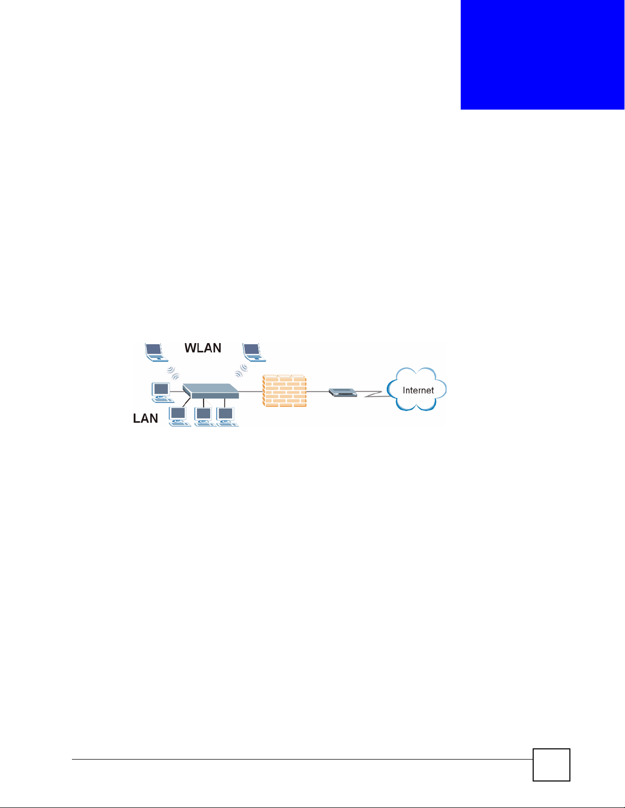
The NBG-510S Wireless SSL Remote Access Gateway provides wireless connectivity, shared
Internet access, and firewall protection. It also provides easy, secure remote user access for file
sharing and management of home network computers.
Figure 1 Secure Wired and Wireless Internet Access Through Broadband Modem or Router
NBG-510S
• The ZyXEL Device is easy to install and configure.
• Directly connect computers or Ethernet devices to the four-port LAN switch.
• The wireless LAN feature (WLAN) supports IEEE 802.11b and IEEE 802.1g devices as
well as Super G wireless technology for enhanced wireless data throughput speeds.
• NAT and DHCP server features let you share high-speed Internet access through a
broadband modem or router.
• Strong firewall protection secures your network from attacks.
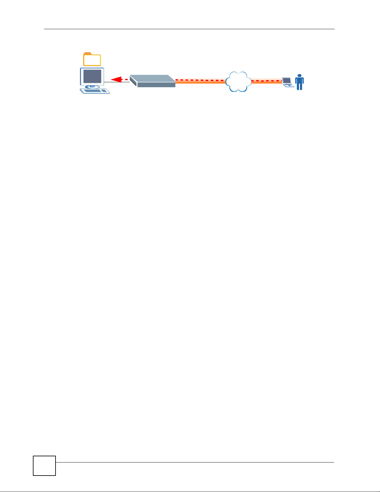
1.1.1 Remote User Access Secured by SSL
The secure remote access portal (user portal) makes it easy to give remote users secure access
to shared files on your home computers. The secure remote access uses SSL (the Secure
Socket Layer protocol), so no security software installation is required. Remote users can use
Internet Explorer or other standard web browsers. Here remote user A uses a web browser to
go to the secure remote access portal and securely access a shared file on a computer behind
the ZyXEL Device.
NBG-510S User’s Guide
27
Page 28
Chapter 1 Introducing the ZyXEL Device
Figure 2 SSL-protected File Sharing for Remote Users
NBG-510S
Internet
SSL
The secure remote access portal also allows secure remote desktop connections for managing
computers on your network. The secure remote access screens (user portal) includes the
screens the remote users log into and use for secure file sharing and remote computer
management.
1.2 Good Habits for Managing the ZyXEL Device
Use the web configurator for everyday management of the ZyXEL Device with a (supported)
web browser.
Do the following things regularly to make the ZyXEL Device more secure and to manage the
ZyXEL Device more effectively.
• Change the password. Use a password that is not easy to guess and that consists of
different types of characters, such as numbers and letters.
• Write down the password and put it in a safe place.
• Back up the configuration (and make sure you know how to restore it). Restoring an
earlier working configuration may be useful if the device becomes unstable or even
crashes. If you forget your password, you will have to reset the ZyXEL Device to its
factory default settings. If you backed up an earlier configuration file, you would not have
to totally re-configure the ZyXEL Device. You could simply restore your last
configuration.
https://
A
28
NBG-510S User’s Guide
Page 29
CHAPTER 2
Hardware Connection
This chapter describes the port connections and LEDs.
2.1 Ports and Connectors
This section describes the ports and connectors on the ZyXEL Device. Refer to the Quick Start
Guide for information on connecting the ZyXEL Device for initial setup and basic
configuration.
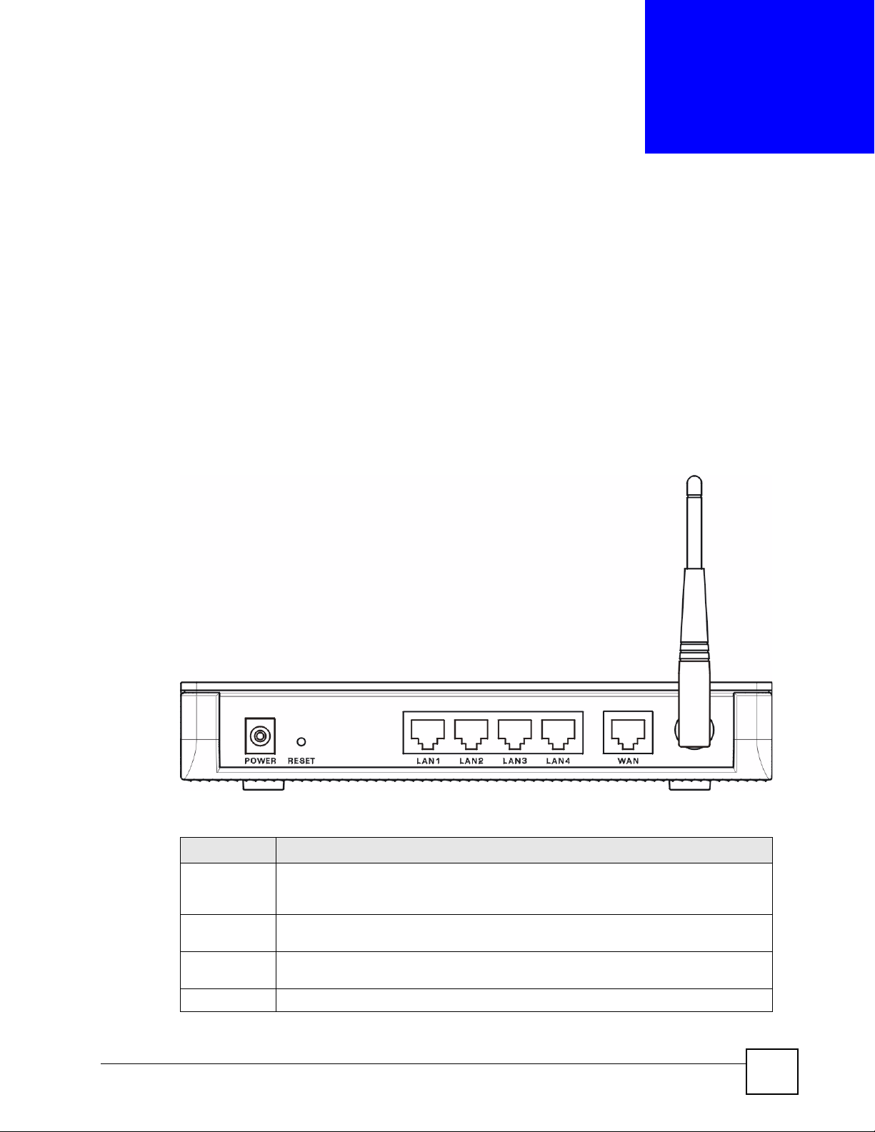
Figure 3 Rear Panel
The following table describes the port connections.
Table 1 Rear Panel
LABEL DESCRIPTION
POWER Use the included power adaptor to connect the POWER socket to an appropriate
RESET Use this button to reset the ZyXEL Device to the factory default settings. See Section
LAN 1~4 Use Ethernet cables to connect these 10/100 Mbps Ethernet ports to computers,
WAN Use an Ethernet cable to connect this Ethernet port to a broadband modem or router.
NBG-510S User’s Guide
power source. See Appendix A on page 171 for the power adaptor’s
specifications.
3.6 on page 38 for details.
servers or Ethernet devices on your network.
29
Page 30
Chapter 2 Hardware Connection
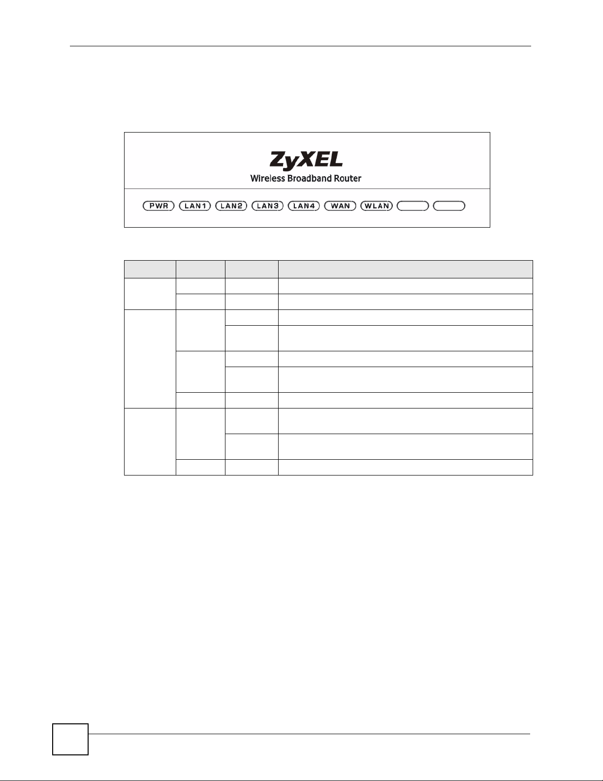
2.2 LEDs
The following table describes the LEDs (lights) on the ZyXEL Device.
Figure 4 LEDs
Table 2 LEDs
LED COLOR STATUS DESCRIPTION
PWR Green On The ZyXEL Device is receiving power.
LAN/WAN Yellow On This port has a successful 100 Mbps connection.
Green On This port has a successful 10 Mbps connection.
WLAN Green On The ZyXEL Device’s wireless LAN connection is ready, but is
Off The ZyXEL Device is not receiving power.
Blinking This port has a successful 100 Mbps connection and is
sending/receiving data.
Blinking This port has a successful 10 Mbps connection and is sending/
receiving data.
Off This port does not have a successful Ethernet connection.
not sending/receiving data through the wireless LAN.
Blinking The ZyXEL Device is sending/receiving data through the
wireless LAN.
Off The wireless LAN is not ready or has failed.
30
NBG-510S User’s Guide
Page 31

CHAPTER 3
The Web Configurator
This chapter introduces the web configurator and shows you how to log in as an administrator.
3.1 Web Configurator Overview
The web configurator is an HTML-based management interface that allows easy ZyXEL
Device setup and management via Internet browser. The recommended screen resolution is
1024 by 768 pixels. Use one of the following web browsers:
• Internet Explorer 5 (administrator login only), 6.0, or 7.0
• Netscape Navigator 7.2
• Mozilla 1.7.13,
• FireFox 1.5.0.9 or 2.0.
In order to use the web configurator you need to allow:
• Web browser pop-up windows from your device. Web pop-up blocking is enabled by
default in Windows XP SP (Service Pack) 2.
• JavaScripts (enabled by default).
• Java permissions (enabled by default).
3.2 Logging into the ZyXEL Device
1 Make sure you have properly connected the ZyXEL Device to your network. See the
Quick Start Guide.
2 Open your web browser, and go to http://192.168.1.1 (the default LAN IP address).
3 A security alert and/or certificate screen displays. Click OK and/or Ye s to continue.
NBG-510S User’s Guide
31
Page 32

Chapter 3 The Web Configurator
Figure 5 Login: Security Message
4 The Login screen appears. For administrator access, type the administrator user name
(default: “admin”) and password (default: “1234”). For secure remote user access (using
the user portal), type your remote user account’s user name and password (see Chapter
25 on page 155 for more on using the secure remote user screens).
• If you are using a computer that is also used by others, select I am connecting via
public computer. Your web browser cache will be automatically cleaned once you
terminate the connection. This prevents anyone from obtaining information from the
browser cache.
• If you are using your computer to access the ZyXEL Device, select I am connecting
via my own computer. Your web browser cache will not be cleaned after you log out.
Figure 6 Login: Enter Account Information
5 The initial screen displays as shown.
• Click Setup Wizard to configure the ZyXEL Device using the wizard screens and
proceed to Chapter 5 on page 41.
• Click Advanced Setup to access the main screen (see Figure 10 on page 34) and
configure the ZyXEL Device using the advanced configuration screens.
32
NBG-510S User’s Guide
Page 33

Chapter 3 The Web Configurator
Figure 7 Login: Initial Screen
If another person is currently logged in using the administrator account, you are not able
to log in and a message displays in the screen as shown next.
Figure 8 Login: Admin Already Logged In
6 Another certificate screen displays. Click Ye s to continue.
• The ZyXEL Device automatically forwards administrator sessions to its HTTPS
server on TCP port 8443.
• The ZyXEL Device automatically forwards secure remote access sessions to its
HTTPS server on TCP port 443.
" If the ZyXEL Device is behind a firewall or NAT router, make sure you
configure port forwarding or a firewall rule to allow traffic to the ZyXEL Device
on TCP port 8443 for administration connections and TCP port 443 for secure
remote access connections.
NBG-510S User’s Guide
33
Page 34

Chapter 3 The Web Configurator
Figure 9 Login Screen: Security Message for Administrator Login
7 The main screen displays.
3.3 Web Configurator Main Screen
The Status screen is the main screen and it is the first screen that displays every time you
access the web configurator as an administrator.
Figure 10 Main Screen
B
C
A
34
D
The main screen is divided into these parts:
• A - title bar
NBG-510S User’s Guide
Page 35

• B - navigation panel
• C - main window
• D - status bar
3.3.1 Title Bar
The title bar provides some icons in the upper right corner.
Chapter 3 The Web Configurator
Wizard
About
Logout
The icons provide the following functions.
Table 3 Title Bar: Web Configurator Icons
ICON DESCRIPTION
Wizard Click this icon to open one of the web configurator wizard.
About Click this icon to display basic information about the ZyXEL Device.
Logout Click this icon to log out of the web configurator.
3.3.2 Navigation Panel
Use the menu items on the navigation panel to open screens to configure ZyXEL Device
features. The following tables describe each menu item.
Table 4 Menu Summary
LINK TAB FUNCTION
Status See the ZyXEL Device’s general device information, system status, system
Network
Wireless LAN Configure the wireless LAN card for wireless clients to connect to.
WAN Internet
Connection
Advanced Configure the WAN interface’s multicast setting.
LAN Configure the LAN interface to connect to the local network.
DHCP Server General Turn the DHCP server function on or off and configure the IP address pool.
Client List See the list of DHCP clients using the ZyXEL Device and the IP addresses
NAT Port Forwarding Allow users on the WAN to access local servers.
Port Triggering Allow computers on the LAN to dynamically take turns using services that
DDNS Dynamic DNS let you use a domain name with a dynamic WAN IP address.
Security
Access Control Access Control Use firewall rules to allow or block applications. Use QoS to give higher
Schedules Configure schedules for applying firewall rules.
Content Filter Block certain web features and URL keywords.
resource usage, interface status, and wireless status.
Configure the WAN interface for Internet access.
assigned to them.
use a range of ports.
priority to traffic from specific applications (like voice).
NBG-510S User’s Guide
35
Page 36

Chapter 3 The Web Configurator
Table 4 Menu Summary (continued)
LINK TAB FUNCTION
Management
UPnP UPnP provides simple peer-to-peer network connectivity between devices.
Static Route Use static routes to tell the ZyXEL Device about networks beyond the
directly connected ones.
Maintenance
System General Configure the ZyXEL Device’s administrative settings.
Time Setting Configure the ZyXEL Device’s time and date settings.
Logs View log entries.
To ol s Firmware Upload firmware to your ZyXEL Device
Configuration Backup and restore the ZyXEL Device configuration or reset the factory
defaults.
Restart Reboot the ZyXEL Device.
Box Access Select which services can access the ZyXEL Device from the WAN.
Diagnostic Tools Check connectivity to a website or computer on the Internet, check the
Internet connection’s behavior, and resolve a domain name’s IP address.
User Portal The secure remote user portal lets remote users securely access LAN
resources. Remote access to LAN computers is made secure through SSL
or HTTPS. Configure permissions for authorized remote users to access
specific network resources. In addition to accessing folders and files,
remote users can be authorized to use remote desktop connections to
remotely control LAN computers.
Admin Info Configure the portal administrator’s details.
User Info User Info Create and manage secure remote portal user accounts.
Copy User
Views
Manage
Servers
Manage Views Edit each secure remote portal user’s collection of accessible files and
Desktop Links Configure secure remote portal user access for using remote desktop
Copy a portal user’s collection of accessible resources (view) to another
user.
Edit the list of LAN resources that secure remote portal users can access.
folders.
connections to remotely control LAN computers. The remote users may use
VNC (Virtual Network Computing) or RDP (Remote Desktop) protocol.
3.3.3 Main Window
The main window shows the screen you select in the menu. It is discussed in the rest of this
document.
Right after you log in, the Status screen is displayed. See Chapter 4 on page 39 for more
information about the Status screen.
3.3.4 Status Bar
Check the status bar when you click Apply or OK to verify that the configuration has been
updated.
36
NBG-510S User’s Guide
Page 37

3.4 Login Timeout
By default, the web configurator automatically logs you out after 5 minutes (300 seconds) of
inactivity. When this happens, a warning screen displays and you will be redirected to the
login screen. Simply log into the web configurator again to continue your management tasks.
Figure 11 Timeout Message
3.4.1 Changing Login Timeout
To change the default login timeout period click Maintenance > General to display the
following screen. In the Administrator Inactivity Timer field, specify a time (in minutes).
Click Apply to save the changes. A value of "0" means a management session never times out,
no matter how long it has been left idle (not recommended).
You can also use this screen to change the administrator login password (refer to Section 3.5
on page 37).
Chapter 3 The Web Configurator
Figure 12 Maintenance: Password
3.5 Changing Password
It is highly recommended that you change the default administrator login password in the
Change Password screen after the first successful login. Click Maintenance > General to
display the configuration screen (see Figure 12 on page 37).
NBG-510S User’s Guide
37
Page 38

Chapter 3 The Web Configurator
In the Old Password field, enter the current password. Enter the new password (up to 31
printable ASCII characters with no spaces allowed) in the New Password and the Re-type to
Confirm fields. Click OK to save the changes.
3.6 Device Reset
You can reset the ZyXEL Device using the RESET button. You need to reset your ZyXEL
Device to the factory default settings if
• you have changed the default administrator login password and have now forgotten it.
or
• you want to start configuring the ZyXEL Device again from the default settings.
" Resetting your device back to the defaults erases all your custom settings.
Follow the steps below to reset the ZyXEL Device using the RESET button panel.
1 Make sure the PWR LED is on and not blinking.
2 Use a pointed object to press the RESET button in for five seconds and release it. The
device restarts with the factory default settings (the default LAN IP address is
192.168.1.1 and the administrator login password is 1234).
3 Wait until the device finished rebooting before accessing the web configurator again.
38
NBG-510S User’s Guide
Page 39

CHAPTER 4
Status
This chapter explains the Status screen, which is the screen you see when you first log in to
the ZyXEL Device.
4.1 Status Screen
Use the Status screen to look at the ZyXEL Device’s general device information, system
status, system resource usage, licensed service status, and interface status. To access this
screen, click Status in the navigation panel.
Figure 13 Status
The following table describes the labels in this screen.
Table 5 Status
LABEL DESCRIPTION
Device
Information
System Name This field displays the name used to identify the ZyXEL Device on any network.
Model Name This field displays the model name of this ZyXEL Device.
Serial Number This field displays the serial number of this ZyXEL Device.
LAN MAC
Address
NBG-510S User’s Guide
This field displays the MAC address assigned to the LAN interface.
39
Page 40

Chapter 4 Status
Table 5 Status (continued)
LABEL DESCRIPTION
WAN MAC
Address
Firmware
Versi on
System Status
System Uptime This field displays how long the ZyXEL Device has been running since it last
Current Date/
Time
System
Resource
CPU Usage This field displays what percentage of the ZyXEL Device’s processing capability is
Memory Usage This field displays what percentage of the ZyXEL Device’s RAM is currently being
Onboard Flash
Usage
Interface Status
Summary
Name This field displays the name of each Ethernet interface.
Status This field displays the current connection status of each interface.
IP Addr/Netmask This field displays the current IP address and subnet mask assigned to the
IP Assignment This field displays how the interface gets its IP address.
Renew Click Renew to update the IP address for the interface. This field displays n/a if the
Wireless
Status Up displays when the WLAN is enabled. Down displays when the WLAN is
MAC Address This field displays the ZyXEL Device’s MAC address for wireless LAN connections.
Name (SSID)
Channel
Encryption This field displays what type of encryption the ZyXEL Device is using for wireless
Link Rate This displays the maximum transmission rate in Mb/s.
This field displays the MAC address assigned to the WAN interface. If you
configured the WAN interface’s MAC address (see , the configured MAC address
displays here instead of the factory default.
This field displays the version number of the firmware the ZyXEL Device is
currently using.
restarted or was turned on.
This field displays the current date and time in the ZyXEL Device. The format is
yyyy-mm-dd hh:mm:ss.
currently being used.
used.
This field displays what percentage of the ZyXEL Device’s onboard flash memory is
currently being used.
interface. Unavailable displays if the interface did not receive an IP address and
subnet mask via DHCP or the ZyXEL Device could not connect to ISP.
Static - This interface has a static IP address.
DHCP Client - This interface gets its IP address from a DHCP server.
PPPOE - This interface gets its IP address from a PPPoE server.
PPTP - This interface gets its IP address from a PPTP server.
interface has a static IP address.
disabled.
This is the descriptive name used to identify the ZyXEL Device in the wireless LAN.
This is the channel number used by the ZyXEL Device now.
LAN connections.
40
NBG-510S User’s Guide
Page 41

CHAPTER 5
Setup Wizard
This chapter provides information on the Wizard setup screens in the web configurator.
5.1 Wizard Setup Overview
Use the setup wizard screens to configure your Internet access settings.
Follow the steps to configure the wizard screens. Click Next > in each wizard screen to
continue.
1 To display the setup wizard, click Setup Wizard in the initial main screen.
Figure 14 Wizard Welcome Screen
2 Create a new administrator password. Enter a unique password (up to 31 printable
ASCII characters with no spaces allowed).
Figure 15 Wizard: Administration Settings
NBG-510S User’s Guide
41
Page 42

Chapter 5 Setup Wizard
" You cannot use the admin account to access network resources.
3 Select the ZyXEL Device’s time zone and whether or not you use Daylight Saving Time.
You can select a time server from the list or select Custom and enter another time
server.
Figure 16 Wizard: Date and Time Settings
4 If the Internet Service Provider (ISP) uses your computer’s hardware (MAC) address in
authenticating your Internet access, enable MAC cloning and enter your computer’s
MAC address to have the ZyXEL Device use your computer’s MAC address.
Figure 17 Wizard: MAC Cloning
42
NBG-510S User’s Guide
Page 43

Chapter 5 Setup Wizard
5 Use DHCP client if your ISP did not give you any Internet access settings. Otherwise
select the mode that your ISP uses and enter the Internet access settings exactly as the
ISP provided them.
Figure 18 Wizard: Internet Access
6 Wait while the ZyXEL Device applies your Internet access settings. Then click Next.
Figure 19 Wizard: Applying Internet Settings
7 Click Close in the final wizard screen.
NBG-510S User’s Guide
43
Page 44

Chapter 5 Setup Wizard
Figure 20 Wizard: Applying Internet Settings
44
NBG-510S User’s Guide
Page 45

CHAPTER 6
Tutorials
6.1 Secure Remote Access Configuration Overview
Here is a brief summary of how to configure secure remote access (user portal) screens to
allow remote users to securely access and upload shared files on the computers on your
network. See the Quick Start Guide for an example.
6.1.1 Configure Secure Remote Access
This example is for a Windows computer.
1 Use Windows Explorer to share out the computer folders that the remote users can
access.
2 Open your Internet browser (Internet Explorer for example) and log into the ZyXEL
Device (see Section 3.2 on page 31 for details). Use the User Portal > User Info screens
(Chapter 20 on page 135) to create user names and passwords for the remote users.
3 Use the User Portal > Manage Views screens (Chapter 23 on page 143) to configure
what files each remote user can access on the LAN.
• Configure folder categories and references to allow a remote user upload files.
• You can configure categories and references for the guest account.
• User Portal > User Info > Copy User Views can help speed up the process if you are
configuring multiple accounts with similar views.
6.1.2 Test Secure Remote Access
1 Open another browser window (Internet Explorer for example) and log into the ZyXEL
Device using a secure remote access account’s username and password (see Chapter 25
on page 155).
2 You see a screen with folders of the files you can access. Browse through the screens
and make sure you can view and download files. Use the Folders screens to upload files.
6.2 Secure Remote Desktop Connections
This example shows how to use Windows Remote Desktop Connection software (included in
Windows XP) with the secure remote access portal for secure remote desktop connections for
managing a computer on your network.
NBG-510S User’s Guide
45
Page 46

Chapter 6 Tutorials
6.2.1 Configure the Computer to be Managed
Here is how to configure Windows Remote Desktop Connection on the LAN computer that
you want to manage (a Windows XP computer in this example).
1 From your computer desktop, right-click My Computer and select Properties.
Figure 21 My Computer
2 Click the Remote tab, select Allow users to connect remotely to this computer, and
click OK. This allows any of the computer’s administrator user accounts to remotely
control the computer. If you want to manage which accounts can remotely control the
computer, click Select Remote Users.
Figure 22 My Computer > Properties > Remote
46
NBG-510S User’s Guide
Page 47

6.2.2 Configure the ZyXEL Device
You configure policies for the LAN computers to be managed in the ZyXEL Device’s User
Portal > Desktop Links screens.
1 Log into the ZyXEL Device and click User Portal > Desktop Links. Click Manage
View for the user you want to let control the LAN computer (bob in this example).
Figure 23 User Portal > Desktop Links
2 Click the Add New Policy icon.
Figure 24 User Portal > Desktop Links > Manage View
Chapter 6 Tutorials
3 Configure the policy. The policy name (reference name) here is example. Windows
Remote Desktop Connection uses RDP protocol. The computer is at LAN IP address
192.168.1.33. This example uses the default port settings (see Table 56 on page 153 for
details about the port settings). Click Apply Changes.
Figure 25 User Portal > Desktop Links > Manage View > Add
NBG-510S User’s Guide
47
Page 48

Chapter 6 Tutorials
6.2.3 Use the Secure Remote Desktop Connection
1 Open a browser window from a remote computer and log into the secure remote access
screens using the bob account. Click OK, Ye s , or Run in any security alert or certificate
screens that display. See Section 25.2 on page 155 for more login details.
Figure 26 Secure Remote Access Login
2 Click Desktop to open the following screen. Click RemoteDesktopAccess to open a
screen with links for the LAN computers you can manage.
48
NBG-510S User’s Guide
Page 49

Figure 27 Desktop
Chapter 6 Tutorials
3 Roll your mouse over the (example) link to display the loopback IP address and port
number as shown next. The following steps show how to enter the loopback IP address
and port number in the remote computer’s Windows Remote Desktop Connection
software to use in communicating with the LAN computer you are managing.
Figure 28 Desktop Links
4 Stay logged into the ZyXEL Device’s secure remote access portal. In Windows, click
Start > Programs > Accessories > Remote Desktop Connection.
NBG-510S User’s Guide
49
Page 50

Chapter 6 Tutorials
Figure 29 Start > Programs > Accessories > Remote Desktop Connection
5 Enter the loopback IP address and port number from the desktop link (127.0.0.2 and
3389 in this example) separated by a colon, as shown here. Then click OK.
Figure 30 Entering the IP Address and Port Number
6 A login screen opens for the LAN computer. After you log in using one of the LAN
computer’s administrator accounts, you can manage the LAN computer.
• Stay logged into the ZyXEL Device’s secure remote access portal.
• Make sure the remote computer is not running a remote desktop server on the same
port number.
6.3 Wireless Tutorial
The following sections give examples of how to set up the ZyXEL Device and wireless client
for wireless communication using the following parameters. The wireless clients can access
the Internet through the ZyXEL Device wirelessly. See Chapter 7 on page 61 for more on the
ZyXEL Device’s wireless LAN configuration. See the Quick Start Guide for an example of
configuring secure remote access.
50
NBG-510S User’s Guide
Page 51

6.4 Example Parameters
SSID SSID_Example3
Channel 6
Security WPA-PSK
(Pre-Shared Key: ThisismyWPA-PSKpre-sharedkey)
802.11 mode IEEE 802.11b/g
In this chapter, the ZyXEL Device is also referred to as an access point (AP). A computer with
a wireless network card or USB/PCI adapter is referred to here as a “wireless client”.
This chapter uses the M-302 utility screens as an example for the wireless client. The screens
may vary for different models.
6.5 Configuring the ZyXEL Device
Follow the steps below to configure the wireless settings on your ZyXEL Device.
Chapter 6 Tutorials
1 Open the Network > Wireless LAN screen in the web configurator.
Figure 31 Network > Wireless LAN
2 Make sure the Enable Wireless LAN check box is selected.
3 Enter SSID_Example3 as the SSID and select a channel.
4 Set security mode to WPA-PSK and enter ThisismyWPA-PSKpre-sharedkey in the
Pre-Shared Key field. Click Apply.
5 Open the Status screen. Under Wireless, verify that the wireless Status is Up, the
Name(SSID) is SSID_Example3, and the Encryption is WPA-PSK.
NBG-510S User’s Guide
51
Page 52

Chapter 6 Tutorials
Figure 32 Status: Wireless Settings Example
6 Now that you have configured the ZyXEL Device’s wireless settings, continue with the
next section to configure wireless clients to connect to the ZyXEL Device.
6.6 Configuring the Wireless Client
This section describes how to connect the wireless client to a network.
6.6.1 Connecting to a Wireless LAN
The following sections show you how to join a ZyXEL wireless client (not included) to the
wireless network. This example uses the ZyXEL utility that comes with a ZyXEL wireless
client. In the following diagram, the wireless client is labelled C and the access point is
labelled AP.
There are three ways to connect the client to an access point.
52
• Configure nothing and leave the wireless client to automatically scan for and connect to
any available network that has no wireless security configured.
• Manually connect to a network.
• Configure a profile to have the wireless client automatically connect to a specific network
or peer computer.
NBG-510S User’s Guide
Page 53

Chapter 6 Tutorials
This example illustrates how to manually connect your wireless client to an access point (AP)
which is configured for WPA-PSK security and connected to the Internet. Before you connect
to the access point, you must know its Service Set IDentity (SSID) and WPA-PSK pre-shared
key. In this example, the SSID is “SSID_Example3” and the pre-shared key is
“ThisismyWPA-PSKpre-sharedkey”.
After you install the ZyXEL utility and then insert the wireless client, follow the steps below
to connect to a network using the Site Survey screen.
1 Open the ZyXEL utility and click the Site Survey tab to open the screen shown next.
2 The wireless client automatically searches for available wireless networks. Click Scan if
you want to search again. If no entry displays in the Available Network List, that means
there is no wireless network available within range. Make sure the AP or peer computer
is turned on or move the wireless client closer to the AP or peer computer.
3 When you try to connect to an AP with security configured, a window will pop up
prompting you to specify the security settings. Enter the pre-shared key and leave the
encryption type at the default setting.
Use the Next button to move on to the next screen. You can use the Back button at any
time to return to the previous screen, or the Exit button to return to the Site Survey
screen.
Figure 33 ZyXEL Utility: Security Settings
4 The Confirm Save window appears. Check your settings and click Save to continue.
NBG-510S User’s Guide
53
Page 54

Chapter 6 Tutorials
Figure 34 ZyXEL Utility: Confirm Save
5 The ZyXEL utility returns to the Link Info screen while it connects to the wireless
Figure 35 ZyXEL Utility: Link Info
network using your settings. When the wireless link is established, the ZyXEL utility
icon in the system tray turns green and the Link Info screen displays details of the active
connection. Check the network information in the Link Info screen to verify that you
have successfully connected to the selected network. If the wireless client is not
connected to a network, the fields in this screen remain blank.
6 Open your Internet browser and enter http://www.zyxel.com or the URL of any other
web site in the address bar. If you are able to access the web site, your wireless
connection is successfully configured.
If you cannot access the web site, try changing the encryption type in the Security
Settings screen, check the Troubleshooting section of this User's Guide or contact your
network administrator.
6.6.2 Creating and Using a Profile
A profile lets you automatically connect to the same wireless network every time you use the
wireless client. You can also configure different profiles for different networks, for example if
you connect a notebook computer to wireless networks at home and at work.
This example illustrates how to set up a profile and connect the wireless client to an access
point configured for WPA-PSK security. In this example, the SSID is “SSID_Example3”, the
profile name is “PN_Example3” and the pre-shared key is “ThisismyWPA-PSKpresharedkey”. You have chosen the profile name “PN_Example3”.
54
NBG-510S User’s Guide
Page 55

Chapter 6 Tutorials
1 Open the ZyXEL utility and click the Profile tab to open the screen shown next. Click
Add to configure a new profile.
Figure 36 ZyXEL Utility: Profile
2 The Add New Profile screen appears. The wireless client automatically searches for
available wireless networks, which are displayed in the Scan Info box. Click on Scan if
you want to search again. You can also configure your profile for a wireless network that
is not in the list.
Figure 37 ZyXEL Utility: Add New Profile
3 Give the profile a descriptive name (of up to 32 printable ASCII characters). Select
Infrastructure and either manually enter or select the AP's SSID in the Scan Info table
and click Select.
4 Choose the same encryption method as the AP to which you want to connect (In this
example, WPA-PSK).
Figure 38 ZyXEL Utility: Profile Security
NBG-510S User’s Guide
55
Page 56

Chapter 6 Tutorials
5 This screen varies depending on the encryption method you selected in the previous
Figure 39 ZyXEL Utility: Profile Encryption
6 In the next screen, leave both boxes checked.
Figure 40 Profile: Wireless Protocol Settings.
screen. Enter the pre-shared key and leave the encryption type at the default setting.
7 Verify the profile settings in the read-only screen. Click Save to save and go to the next
screen.
Figure 41 Profile: Confirm Save
8 Click Activate Now to use the new profile immediately. Otherwise, click the Activate
Later button.
If you clicked Activate Later, you can select the profile from the list in the Profile
screen and click Connect to activate it.
56
NBG-510S User’s Guide
Page 57

" Only one profile can be activated and used at any given time.
Figure 42 Profile: Activate
9 When you activate the new profile, the ZyXEL utility returns to the Link Info screen
while it connects to the AP using your settings. When the wireless link is established, the
ZyXEL utility icon in the system tray turns green and the Link Info screen displays
details of the active connection.
10 Open your Internet browser, enter http://www.zyxel.com or the URL of any other web
site in the address bar and press ENTER. If you are able to access the web site, your new
profile is successfully configured.
11 If you cannot access the Internet go back to the Profile screen, select the profile you are
using and click Edit. Check the details you entered previously. Also, refer to the
Troubleshooting section of this User's Guide or contact your network administrator if
necessary.
Chapter 6 Tutorials
NBG-510S User’s Guide
57
Page 58

Chapter 6 Tutorials
58
NBG-510S User’s Guide
Page 59

PART II
Network
• Wireless LAN (61)
• WA N ( 6 9)
• LAN (77)
• DHCP (79)
• NAT and Firewall (WAN to LAN) (81)
• DDNS (89)
59
Page 60

60
Page 61

CHAPTER 7
Wireless LAN
This chapter discusses how to configure the wireless network settings in your ZyXEL Device.
See Appendix C on page 181 for more detailed information about wireless networks.
7.1 Wireless Network Overview
The following figure provides an example of a wireless network.
Figure 43 Example of a Wireless Network
The wireless network is the part in the blue circle. In this wireless network, devices A and B
are called wireless clients. The wireless clients use the access point (AP) to interact with other
devices (such as the printer) or with the Internet. Your ZyXEL Device is the AP.
Every wireless network must follow these basic guidelines.
• Every wireless client in the same wireless network must use the same SSID.
The SSID is the name of the wireless network. It stands for Service Set IDentity.
• If two wireless networks overlap, they should use different channels.
Like radio stations or television channels, each wireless network uses a specific channel,
or frequency, to send and receive information.
NBG-510S User’s Guide
61
Page 62

Chapter 7 Wireless LAN
• Every wireless client in the same wireless network must use security compatible with the
AP.
Security stops unauthorized devices from using the wireless network. It can also protect
the information that is sent in the wireless network.
7.2 Wireless Security Overview
The following table shows the relative strengths of common types of wireless security. Use the
strongest security that every wireless client in the wireless network supports.
Table 6 Wireless Security Types
NO RADIUS SERVER RADIUS SERVER
Weakest No Security
Static WEP
WPA-PSK
Strongest WPA2-PSK WPA2
If you have a RADIUS server, you can use WPA or WPA2 so users have to log into the
wireless network before using it. This is called user authentication. RADIUS servers are more
common in businesses (WPA and WPA2 are also called the enterprise version of WPA).
WPA
If you do not have a RADIUS server, the strongest wireless security you can use is WPA2PSK (WPA2-PSK and WPA-PSK are also known as the personal version of WPA).
" It is recommended that wireless networks use WPA-PSK, WPA, or stronger
security. WEP is better than no security, but it is still possible for unauthorized
devices to figure out the original information pretty quickly.
When you select WPA2 or WPA2-PSK in your ZyXEL Device, you can also select an option
(WPA Compatible) to support WPA as well. In this case, if some wireless clients support
WPA and some support WPA2, you should set up WPA2-PSK or WPA2 (depending on the
type of wireless network login) and select the WPA Compatible option in the ZyXEL Device.
7.2.1 SSID
Normally, the AP acts like a beacon and regularly broadcasts the SSID in the area. You can
hide the SSID instead, in which case the AP does not broadcast the SSID. In addition, you
should change the default SSID to something that is difficult to guess.
This type of security is fairly weak, however, because there are ways for unauthorized devices
to get the SSID. In addition, unauthorized devices can still see the information that is sent in
the wireless network.
62
NBG-510S User’s Guide
Page 63

7.2.2 User Authentication
You can use WPA or WPA2 to have a RADIUS server authenticate users before they can use
the wireless network. You store each user’s user name and password on the RADIUS server.
However, every wireless client in the wireless network has to support IEEE 802.1x to do this.
Unauthorized devices can still see the information that is sent in the wireless network, even if
they cannot use the wireless network. Furthermore, there are ways for unauthorized wireless
users to get a valid user name and password. Then, they can use that user name and password
to use the wireless network.
7.2.3 Encryption
Wireless networks can use encryption to protect the information that is sent in the wireless
network. Encryption is like a secret code. If you do not know the secret code, you cannot
understand the message.
Many types of encryption use a key to protect the information in the wireless network. The
longer the key, the stronger the encryption. Every wireless client in the wireless network must
have the same key.
Chapter 7 Wireless LAN
7.3 Wireless LAN Screen
" If you are configuring the ZyXEL Device from a computer connected to the
wireless LAN and you change the ZyXEL Device’s SSID, channel or security
settings, you will lose your wireless connection when you press Apply to
confirm. You must then change the wireless settings of your computer to
match the ZyXEL Device’s new settings.
Click Network > Wireless LAN to open the General screen.
Figure 44 Network > Wireless LAN
NBG-510S User’s Guide
63
Page 64

Chapter 7 Wireless LAN
The following table describes the general wireless LAN labels in this screen.
Table 7 Network > Wireless LAN
LABEL DESCRIPTION
Enable a
Wireless LAN
Name(SSID) (Service Set IDentity) The SSID identifies the Service Set with which a wireless
Hide SSID Select this check box to hide the SSID in the outgoing beacon frame so a station
Channel
Selection
Operating
Channel
Apply Click Apply to save your changes back to the ZyXEL Device.
Cancel Click Cancel to begin configuring this screen afresh.
Click the check box to activate wireless LAN.
station is associated. Wireless stations associating to the access point (AP) must
have the same SSID. Enter a descriptive name (up to 32 printable 7-bit ASCII
characters) for the wireless LAN.
cannot obtain the SSID through scanning using a site survey tool.
The range of radio frequencies used by IEEE 802.1 wireless devices is called a
channel. Select a channel ID that is not already in use by a neighboring device.
Select a channel from the drop-down list box. The options vary depending on
whether you are using A or B/G frequency band and the country you are in.
Select Auto Channel to have the ZyXEL Device automatically find a suitable
channel to use.
This displays the channel the ZyXEL Device is currently using.
See the rest of this chapter for information on the other labels in this screen.
7.3.1 No Security
Select No Security to allow wireless stations to communicate with the wireless clients without
any data encryption.
" If you do not enable any wireless security on your ZyXEL Device, your network
is accessible to any wireless networking device that is within range.
Figure 45 Network > Wireless LAN: No Security
64
NBG-510S User’s Guide
Page 65

Chapter 7 Wireless LAN
The following table describes the labels in this screen.
Table 8 Network > Wireless LAN: No Security
LABEL DESCRIPTION
Server Type Choose No Security from the drop-down list box.
Apply Click Apply to save your changes back to the ZyXEL Device.
Cancel Click Cancel to begin configuring this screen afresh.
7.3.2 WEP Encryption
WEP encryption scrambles the data transmitted between the wireless stations and the access
points to keep network communications private. It encrypts unicast and multicast
communications in a network. Both the wireless stations and the access points must use the
same WEP key. Your ZyXEL Device allows you to configure up to four WEP keys but only
one key can be enabled at any one time.
" It is recommended that wireless networks use WPA-PSK, WPA, or stronger
security. WEP is better than no security, but it is still possible for unauthorized
devices to figure out the original information pretty quickly.
In order to configure and enable WEP encryption; click Network > Wireless LAN to display
the General screen. Select Static WEP as the Server Type.
Figure 46 Network > Wireless LAN: Static WEP Encryption
NBG-510S User’s Guide
65
Page 66

Chapter 7 Wireless LAN
The following table describes the wireless LAN security labels in this screen.
Table 9 Network > Wireless LAN: Static WEP Encryption
LABEL DESCRIPTION
Passphrase Enter a passphrase (password phrase) of up to 32 printable characters and click
WEP
Encryption
Authentication
Method
ASCII Select this option in order to enter ASCII characters as WEP key.
Hex Select this option in order to enter hexadecimal characters as a WEP key.
Key 1 to Key 4 The WEP keys are used to encrypt data. Both the ZyXEL Device and the wireless
Apply Click Apply to save your changes back to the ZyXEL Device.
Cancel Click Cancel to begin configuring this screen afresh.
Generate. The ZyXEL Device automatically generates four different WEP keys and
displays them in the Key fields below.
Select 64-bit WEP, 128-bit WEP, or 152-bit WEP to enable data encryption.
This field is activated when you select 64-bit WEP or 128-bit WEP in the WEP
Encryption field.
Select Auto, Open System or Shared Key from the drop-down list box.
The preceding "0x", that identifies a hexadecimal key, is entered automatically.
stations must use the same WEP key for data transmission.
If you chose 64-bit WEP, then enter any 5 ASCII characters or 10 hexadecimal
characters ("0-9", "A-F").
If you chose 128-bit WEP, then enter 13 ASCII characters or 26 hexadecimal
characters ("0-9", "A-F").
If you chose 152-bit WEP, then enter 16 ASCII characters or 232 hexadecimal
characters ("0-9", "A-F").
You must configure at least one key, only one key can be activated at any one time.
The default key is key 1.
7.3.3 WPA-PSK/WPA2-PSK
Click Network > Wireless LAN to display the following screen.
Figure 47 Network > Wireless LAN: WPA-PSK/WPA2-PSK
66
NBG-510S User’s Guide
Page 67

The following table describes the labels in this screen.
Table 10 Network > Wireless LAN: WPA-PSK/WPA2-PSK
LABEL DESCRIPTION
WPA Compatible This check box is available only when you select WPA2-PSK or WPA2 in the
Pre-Shared Key The encryption mechanisms used for WPA/WPA2 and WPA-PSK/WPA2-PSK
Apply Click Apply to save your changes back to the ZyXEL Device.
Cancel Click Cancel to begin configuring this screen afresh.
7.3.4 WPA/WPA2
Click Network > Wireless LAN to display the following screen.
Chapter 7 Wireless LAN
Server Type field.
Select the check box to have both WPA2 and WPA wireless clients be able to
communicate with the ZyXEL Device even when the ZyXEL Device is using
WPA2-PSK or WPA2.
are the same. The only difference between the two is that WPA-PSK/WPA2-PSK
uses a simple common password, instead of user-specific credentials.
Type a pre-shared key from 8 to 63 case-sensitive ASCII characters (including
spaces and symbols). A minimum of 20 characters consisting of letters, upper and
lower case, numbers and symbols is recommended.
Figure 48 Network > Wireless LAN: WPA/WPA2
NBG-510S User’s Guide
67
Page 68

Chapter 7 Wireless LAN
The following table describes the labels in this screen.
Tabl e 11 Network > Wireless LAN: WPA/WPA2
LABEL DESCRIPTION
WPA Compatible This check box is available only when you select WPA2-PSK or WPA2 in the
Authentication Server
IP Address Enter the IP address of the external authentication server in dotted decimal
Port Number Enter the port number of the external authentication server. The default port
Shared Secret Enter a password (up to 64 alphanumeric characters) as the key to be shared
Accounting Server
Active Select this option to enable user accounting through an external authentication
IP Address Enter the IP address of the external accounting server in dotted decimal notation.
Port Number Enter the port number of the external accounting server. The default port number
Shared Secret Enter a password (up to 31 alphanumeric characters) as the key to be shared
Apply Click Apply to save your changes back to the ZyXEL Device.
Cancel Click Cancel to begin configuring this screen afresh.
Server Type field.
Select the check box to have both WPA2 and WPA wireless clients be able to
communicate with the ZyXEL Device even when the ZyXEL Device is using
WPA2-PSK or WPA2.
notation.
number is 1812.
You need not change this value unless your network administrator instructs you
to do so with additional information.
between the external authentication server and the ZyXEL Device.
The key must be the same on the external authentication server and your ZyXEL
Device. The key is not sent over the network.
server.
is 1813.
You need not change this value unless your network administrator instructs you
to do so with additional information.
between the external accounting server and the ZyXEL Device.
The key must be the same on the external accounting server and your ZyXEL
Device. The key is not sent over the network.
68
NBG-510S User’s Guide
Page 69

CHAPTER 8
WAN
This chapter shows you how to configure the WAN screens on the ZyXEL Device for Internet
access.
8.1 WAN IP Address Assignment
Every computer on the Internet must have a unique IP address. The ZyXEL Device can get an
IP address automatically if your ISP gives them out. If you have a static (fixed) IP address
from the ISP, you can manually assign it to the ZyXEL Device’s WAN port.
8.2 DNS Server Addresses
A DNS (Domain Name System) server maps domain names (like www.zyxel.com) to their
corresponding IP addresses (204.217.0.2 in the case of www.zyxel.com). This lets you use
domain names to access web sites without having to know their IP addresses. The ZyXEL
Device can receive the IP address of a DNS server automatically (along with the ZyXEL
Device’s own IP address). You can also manually enter a DNS server IP address in the ZyXEL
Device.
8.3 WAN MAC Address
Every Ethernet device has a unique MAC (Media Access Control) address. The MAC address
is assigned at the factory and consists of six pairs of hexadecimal characters, for example,
00:A0:C5:00:00:02.
If the Internet Service Provider (ISP) uses your computer’s MAC address in authenticating
your Internet access, have the ZyXEL Device use your computer’s MAC address. Once it is
successfully configured, the address will be copied to the ZyXEL Device’s configuration file.
It will not change unless you change the setting or upload a different configuration file.
recommended that you change the MAC address prior to connecting the WAN port.
8.4 WAN DHCP Client Encapsulation
It is
Select DHCP Client encapsulation in the Network > WAN > Internet Connection screen if
your ISP did not assign you a fixed IP address.
NBG-510S User’s Guide
69
Page 70

Chapter 8 WAN
Figure 49 Network > WAN > Internet Connection: DHCP Client Encapsulation
The following table describes the labels in this screen.
Table 12 Network > WAN > Internet Connection: DHCP Client Encapsulation
LABEL DESCRIPTION
WAN MAC
Address
Factory default Select this option to use the factory assigned default MAC address.
Clone this
computer’s MAC
Set WAN MAC
Address
OK Click OK to save your changes.
Cancel Click Cancel to begin configuring this screen afresh.
The MAC address section allows users to configure the WAN port's MAC address
by either using the ZyXEL Device’s MAC address, cloning a computer’s IP
address, or manually entering a MAC address.
Select this option and enter the IP address of the computer on the LAN that is
used for Internet access. Enter the IP address in dotted decimal notation, for
example, 192.168.1.25. Once it is successfully configured, the address will be
copied to the ZyXEL Device’s configuration file. It will not change unless you
change the setting or upload a different configuration file. This MAC address also
displays in the Status screen.
Select this option and enter the MAC address of the computer on the LAN that is
used for Internet access. Enter the MAC address using colons, for example,
00:A0:C5:00:00:02. Once it is successfully configured, the address will be copied
to the ZyXEL Device’s configuration file. It will not change unless you change the
setting or upload a different configuration file. This MAC address also displays in
the Status screen.
8.5 WAN Static IP Encapsulation
Select Static IP encapsulation in the Network > WAN > Internet Connection screen if your
ISP did not assign you a fixed IP address.
70
NBG-510S User’s Guide
Page 71

Figure 50 Network > WAN > Internet Connection: Static IP Encapsulation
Chapter 8 WAN
The following table describes the labels in this screen.
Table 13 Network > WAN > Internet Connection: Static IP Encapsulation
LABEL DESCRIPTION
IP Address Enter your WAN IP address in this field. Enter the IP address in dotted decimal
notation, for example, 192.168.1.25.
Subnet Mask Enter the IP subnet mask in this field.
Gateway IP
Address
Primary DNS
Server
Secondary DNS
Server
WAN MAC
Address
Factory default Select this option to use the factory assigned default MAC address.
Clone this
computer’s MAC
Set WAN MAC
Address
OK Click OK to save your changes back to the ZyXEL Device.
Cancel Click Cancel to begin configuring this screen afresh.
Enter a Gateway IP Address (if your ISP gave you one) in this field.
Enter the DNS server IP address (or addresses) provided by your ISP in these
fields.
The MAC address section allows users to configure the WAN port's MAC address
by either using the ZyXEL Device’s MAC address, cloning a computer’s IP
address, or manually entering a MAC address.
Select this option and enter the IP address of the computer on the LAN that is
used for Internet access. Enter the IP address in dotted decimal notation, for
example, 192.168.1.25. Once it is successfully configured, the address will be
copied to the ZyXEL Device’s configuration file. It will not change unless you
change the setting or upload a different configuration file. This MAC address also
displays in the Status screen.
Select this option and enter the MAC address of the computer on the LAN that is
used for Internet access. Enter the MAC address using colons, for example,
00:A0:C5:00:00:02. Once it is successfully configured, the address will be copied
to the ZyXEL Device’s configuration file. It will not change unless you change the
setting or upload a different configuration file. This MAC address also displays in
the Status screen.
NBG-510S User’s Guide
71
Page 72

Chapter 8 WAN
8.6 WAN PPPoE Encapsulation
The ZyXEL Device supports PPPoE (Point-to-Point Protocol over Ethernet) for a dial-up
connection. If your Internet connection type is PPPoE, select the PPPoE option in the
Network > WAN > Internet Connection screen.
Figure 51 Network > WAN > Internet Connection: PPPoE Encapsulation
The following table describes the labels in this screen.
Table 14 Network > WAN > Internet Connection: PPPoE Encapsulation
LABEL DESCRIPTION
User Name Type the user name given to you by your ISP.
Password Type the password associated with the user name above.
Do you want the
Internet
Connection to be
always on?
Maximum idle
Time
WAN MAC
Address
Factory default Select this option to use the factory assigned default MAC address.
Clone this
computer’s MAC
Set WAN MAC
Address
Select Yes if you do not want the connection to time out. If you select No, you can
configure a maximum idle time before the ZyXEL Device disconnects the Internet
connection.
Set how long the Internet connection can be idle before ZyXEL Device disconnects
it. This only applies if you set the Internet connection to not be always on.
The MAC address section allows users to configure the WAN port's MAC address
by either using the ZyXEL Device’s MAC address, cloning a computer’s IP address,
or manually entering a MAC address.
Select this option and enter the IP address of the computer on the LAN that is used
for Internet access. Enter the IP address in dotted decimal notation, for example,
192.168.1.25. Once it is successfully configured, the address will be copied to the
ZyXEL Device’s configuration file. It will not change unless you change the setting
or upload a different configuration file. This MAC address also displays in the
Status screen.
Select this option and enter the MAC address of the computer on the LAN that is
used for Internet access. Enter the MAC address using colons, for example,
00:A0:C5:00:00:02. Once it is successfully configured, the address will be copied to
the ZyXEL Device’s configuration file. It will not change unless you change the
setting or upload a different configuration file. This MAC address also displays in
the Status screen.
72
NBG-510S User’s Guide
Page 73

Table 14 Network > WAN > Internet Connection: PPPoE Encapsulation (continued)
LABEL DESCRIPTION
OK Click OK to save your changes back to the ZyXEL Device.
Cancel Click Cancel to begin configuring this screen afresh.
8.7 WAN PPTP Encapsulation
Point-to-Point Tunneling Protocol (PPTP) is a network protocol that enables secure transfer of
data from a remote client to a private server, creating a Virtual Private Network (VPN) using
TCP/IP-based networks.
PPTP supports on-demand, multi-protocol and virtual private networking over public
networks, such as the Internet. The screen shown next is for PPTP encapsulation.
If your Internet connection type is PPTP, select the PPTP option in the Network > WAN >
Internet Connection screen.
Figure 52 Network > WAN > Internet Connection: PPTP Encapsulation
Chapter 8 WAN
The following table describes the labels in this screen.
Table 15 Network > WAN > Internet Connection: PPTP Encapsulation
LABEL DESCRIPTION
User Name Type the user name given to you by your ISP.
Password Type the password associated with the user name above.
Do you want the
Internet
Connection to be
always on?
NBG-510S User’s Guide
Select Yes if you do not want the connection to time out. If you select No, you can
configure a maximum idle time before the ZyXEL Device disconnects the Internet
connection.
73
Page 74

Chapter 8 WAN
Table 15 Network > WAN > Internet Connection: PPTP Encapsulation (continued)
LABEL DESCRIPTION
Maximum idle
Time
Server IP Type the IP address of the PPTP server.
IP Address Enter your WAN IP address in this field. You assign this IP address to the WAN
Subnet Mask Enter the IP subnet mask in this field.
WAN MAC
Address
Factory default Select this option to use the factory assigned default MAC address.
Clone this
computer’s MAC
Set WAN MAC
Address
OK Click OK to save your changes back to the ZyXEL Device.
Cancel Click Cancel to begin configuring this screen afresh.
Set how long the Internet connection can be idle before ZyXEL Device disconnects
it. This only applies if you set the Internet connection to not be always on.
interface temporarily to initiate the PPTP negotiation.
The MAC address section allows users to configure the WAN port's MAC address
by either using the ZyXEL Device’s MAC address, cloning a computer’s IP address,
or manually entering a MAC address.
Select this option and enter the IP address of the computer on the LAN that is used
for Internet access. Enter the IP address in dotted decimal notation, for example,
192.168.1.25. Once it is successfully configured, the address will be copied to the
ZyXEL Device’s configuration file. It will not change unless you change the setting
or upload a different configuration file. This MAC address also displays in the
Status screen.
Select this option and enter the MAC address of the computer on the LAN that is
used for Internet access. Enter the MAC address using colons, for example,
00:A0:C5:00:00:02. Once it is successfully configured, the address will be copied to
the ZyXEL Device’s configuration file. It will not change unless you change the
setting or upload a different configuration file. This MAC address also displays in
the Status screen.
8.8 WAN Multicast
Multicast allows packets to be transmitted to multiple hosts. Multicast is an alternative to
unicast packets (packets sent to one computer) and broadcast packets (packets sent to every
computer).
IGMP (Internet Group Management Protocol) is a network-layer protocol used to establish
membership in a multicast group - it is not used to carry user data.
When you have multicast enabled, the ZyXEL Device queries all directly connected networks
when it starts up to gather group membership. After that, the ZyXEL Device periodically
updates this information.
Click Network > WAN > Advanced to open the following screen.
Figure 53 Network > WAN > Advanced
74
NBG-510S User’s Guide
Page 75

The following table describes the labels in this screen.
Table 16 Network > WAN > Advanced
LABEL DESCRIPTION
Multicast Select None to turn off multicasting on the ZyXEL Device.
If any of the LAN computers are using applications that use multicasting, select
IGMP-v3 to have the ZyXEL Device proxy multicast traffic. This is especially useful
for multimedia conferences over the Internet.
Apply Click Apply to save the settings.
Cancel Click Cancel to begin configuring this screen afresh.
Chapter 8 WAN
NBG-510S User’s Guide
75
Page 76

Chapter 8 WAN
76
NBG-510S User’s Guide
Page 77

CHAPTER 9
LAN
This chapter describes the LAN screen you use to configure the LAN IP address on the
ZyXEL Device.
9.1 LAN Overview
Local Area Network (LAN) is a shared communication system to which many computers are
attached. The LAN screens can help you configure a LAN DHCP server, manage IP addresses,
and partition your physical network into logical networks.
9.1.1 Factory LAN Defaults
The LAN parameters of the ZyXEL Device are preset in the factory with an IP address of
192.168.1.1 and a subnet mask of 255.255.255.0 (24 bits)
These parameters should work for the majority of installations.
9.2 LAN Screen
Click Network > LAN to configure the LAN interface settings.
Figure 54 Network > LAN
The following table describes the labels in this screen.
Table 17 Network > LAN
LABEL DESCRIPTION
IP Address Enter an IP address for the LAN interface in dotted decimal notation. For
Subnet Mask Enter the subnet mask for the IP address above. For example. 255.255.255.0.
Apply Click Apply to save the settings.
Cancel Click Cancel to begin configuring this screen afresh.
example, 192.168.1.1.
NBG-510S User’s Guide
77
Page 78

Chapter 9 LAN
78
NBG-510S User’s Guide
Page 79

CHAPTER 10
DHCP
This chapter describes the DHCP screen you use to configure the DHCP server on the ZyXEL
Device.
10.1 DHCP
The ZyXEL Device has built-in DHCP server capability that assigns IP addresses and DNS
servers to systems that support DHCP client capability.
10.1.1 Factory DHCP Defaults
The LAN parameters of the ZyXEL Device are preset in the factory with the DHCP server
enabled with 32 client IP addresses starting from 192.168.1.33.
These parameters should work for the majority of installations.
10.2 DHCP Screen
Click Network > DNCP to configure the DHCP server settings.
Figure 55 Network > DHCP > General
NBG-510S User’s Guide
79
Page 80

Chapter 10 DHCP
The following table describes the labels in this screen.
Table 18 Network > DHCP > General
LABEL DESCRIPTION
Enable DHCP
Server
IP Pool Starting
Address
Pool Size Specify the maximum number of IP addresses you want the ZyXEL Device to
Apply Click Apply to save the settings.
Cancel Click Cancel to begin configuring this screen afresh.
DHCP (Dynamic Host Configuration Protocol, RFC 2131 and RFC 2132) allows
individual clients (computers) to obtain TCP/IP configuration at startup from a
server.
Select this option to enable this feature on the ZyXEL Device and configure the
fields below. When configured as a server, the ZyXEL Device provides TCP/IP
configuration for the clients.
Clear this check box to disable DHCP server on the ZyXEL Device. You must
have another DHCP server on your LAN, or else the computers must be manually
configured.
Enter the first of the contiguous addresses in the IP address pool.
assign to DHCP clients.
10.2.1 DHCP Client List Screen
Click Network > DHCP > Client List to open the following screen. Use this screen to view
current DHCP client information (including IP Address, Host Name and MAC Address) of
all network clients using the ZyXEL Device’s DHCP server.
Figure 56 Network > DHCP > Client List
The following table describes the labels in this screen.
Table 19 Network > DHCP > General
LABEL DESCRIPTION
IP Address This field displays the IP address assigned to a DHCP client.
Host Name This field displays the DHCP client’s host name.
MAC Address The MAC (Media Access Control) or Ethernet address on a LAN (Local Area
Network) is unique for each device (six pairs of hexadecimal notation).
A network interface card such as an Ethernet adapter has a hardwired address
that is assigned at the factory. This address follows an industry standard that
ensures no other adapter has a similar address.
Lease Expires On This field displays how much longer the IP address is offered to that particular
Refresh Click Refresh to reload the DHCP table.
DHCP client.
80
NBG-510S User’s Guide
Page 81

CHAPTER 11
NAT and Firewall (WAN to LAN)
This chapter discusses how to configure NAT on the ZyXEL Device.
11.1 NAT Overview
NAT (Network Address Translation - NAT, RFC 1631) changes the IP address of a host in a
packet. For example, the source address of an outgoing packet, used within one network is
changed to a different IP address known within another network.
11.2 Port Forwarding and Firewall
Incoming sessions (sessions initiated from the WAN and going to the LAN) are blocked by
default. Use port forwarding to allow access from the outside (the Internet) to server(s) on
your LAN.
" Configuring port forwarding also configures the firewall’s WAN to LAN settings.
Port forwarding automatically has the firewall allow unencrypted access from the WAN (the
Internet) to your LAN.
• For secure connections from the Internet to the LAN computers, use the secure remote
user portal (see part VI on page 133).
• To set which services/protocols can access the ZyXEL Device from the WAN (the
Internet), see Section 19.4 on page 129. This allows or disallows remote management of
the ZyXEL Device.
• To control access going from the LAN to the WAN, use the security screens (see part III
on page 91).
A port forwarding set is a list of LAN servers (for example web or FTP) that you can make
accessible to the outside world even though NAT makes your whole inside network appear as
a single machine to the outside world.
In addition to the servers for specified services, NAT supports a default server. A service
request that does not have a server explicitly designated for it is forwarded to the default
server. If the default is not defined, the service request is simply discarded.
NBG-510S User’s Guide
81
Page 82

Chapter 11 NAT and Firewall (WAN to LAN)
" Some residential broadband ISP accounts do not allow you to run any server
processes (such as a Web or FTP server) from your location. Your ISP may
periodically check for servers and may suspend your account if it discovers
any active services at your location. If you are unsure, refer to your ISP.
11.2.1 Configuring Servers Behind Port Forwarding Example
The following example shows the IP addresses of computers on the LAN. You can use port
forwarding to send web and FTP traffic to computer A at IP address 192.168.1.33 and Telnet
traffic to computer B at 192.168.1.34. You could make computer C (at 192.168.1.35) the
default. You assign the LAN IP addresses and the ISP assigns the WAN IP address. The NAT
network appears as a single host on the Internet
Figure 57 Multiple Servers Behind NAT Example
11.3 Port Forwarding Screen
Port forwarding allows traffic from the WAN to be forwarded through the ZyXEL Device. To
change your ZyXEL Device’s port forwarding settings, click Network > NAT > Port
Forwarding. The screen appears as shown. Use this screen to define the local servers to which
to forward incoming services.
" If you do not assign a default host, the ZyXEL Device discards all packets
received for ports that are not specified in this screen or remote management.
Refer to Appendix B on page 177 for port numbers commonly used for particular services.
82
NBG-510S User’s Guide
Page 83

Chapter 11 NAT and Firewall (WAN to LAN)
Figure 58 Network > NAT > Port Forwarding
The following table describes the labels in this screen.
Table 20 NAT Application
LABEL DESCRIPTION
Configuration
Default Host
Settings
Default Host Select a LAN computer from the drop-down list box or select Custom and specify
Apply Click Apply to save the settings.
Cancel Click Cancel to begin configuring this screen afresh.
Port Forwarding
List
Local IP This field displays the host name or IP address of the LAN computer server that
Remote IP This field displays the IP address or domain name of the WAN computer that can
Incoming Service/
Application
Add icon This column provides icons to add, edit, and delete entries.
In addition to the servers for specified services, NAT supports a default server. A
default server receives packets from ports that are not specified in the port
forwarding list. Enable this option to be able to assign a default host.
If you do not assign a default host, the ZyXEL Device discards all packets
received for ports that are not specified in the port forwarding list or remote
management.
a LAN IP address.
receives the Incoming Service/Application.
access the LAN computer. All displays if any WAN computer can access the LAN
computer.
This field displays the service that the ZyXEL Device sends to the computer
configured in the Local IP field.
Click the Add icon to go to the screen where you can configure a new entry.
Click the Edit icon to go to the screen where you can edit the entry.
Click the Delete icon to remove an entry.
11.4 Port Forwarding Add/Edit Screen
Click the Add or Edit icon in the Network > NAT > Port Forwarding screen to open this
screen. Use this screen to configure a port forwarding rule.
NBG-510S User’s Guide
83
Page 84

Chapter 11 NAT and Firewall (WAN to LAN)
Figure 59 Network > NAT > Port Forwarding > Add/Edit
The following table describes the labels in this screen.
Table 21 Network > NAT > Port Forwarding > Add/Edit
LABEL DESCRIPTION
Connections to be
made from
Remote System
for Service Select a service from the drop-down list box or select Custom and specify a port
Redirect to Local
System
Local Service Select what port number the ZyXEL Device when forwarding the service’s traffic to
Should be Select whether the ZyXEL Device should forward (Allowed) or drop (Denied)
Apply Click Apply to save the settings.
Cancel Click Cancel to return to the previous screen without saving your changes.
Select Any to allow connections from any IP address or domain name.
To only allow specific users to access the inside server, select Custom and
specify an IP address or domain name.
number (or numbers) and protocol.
To enter a single port number, enter it in the first field.
To enter a range of port numbers, enter the starting port number in the first field
and the ending port number in the second field.
For a custom service, select the protocol the service uses. Choices are: TCP,
UDP, AH, ESP, and GRE.
Select a LAN computer from the drop-down list box or select Custom and specify
the IP address of a LAN computer.
the LAN.
If the LAN computer uses the same port for the service as the incoming packet’s
source port, select Same as Incoming Service.
If the LAN computer uses a different port for the service, select Custom and
specify the port.
incoming traffic that matches this port forwarding policy.
For example, say you want to allow access for TCP ports 1000 to 2000, but block
TCP port 1500. You could configure a policy that allows TCP ports 1000 to 2000
and then add another policy (higher in the list) that blocks TCP port 1500.
84
NBG-510S User’s Guide
Page 85

11.5 Trigger Port Forwarding
Some services use a dedicated range of ports on the client side and a dedicated range of ports
on the server side. With regular port forwarding you set a forwarding port in NAT to forward a
service (coming in from the server on the WAN) to the IP address of a computer on the client
side (LAN). The problem is that port forwarding only forwards a service to a single LAN IP
address. In order to use the same service on a different LAN computer, you have to manually
replace the LAN computer's IP address in the forwarding port with another LAN computer's IP
address.
Trigger port forwarding solves this problem by allowing computers on the LAN to
dynamically take turns using the service. The ZyXEL Device records the IP address of a LAN
computer that sends traffic to the WAN to request a service with a specific port number and
protocol (a "trigger" port). When the ZyXEL Device's WAN port receives a response with a
specific port number and protocol ("incoming" port), the ZyXEL Device forwards the traffic
to the LAN IP address of the computer that sent the request. After that computer’s connection
for that service closes, another computer on the LAN can use the service in the same manner.
This way you do not need to configure a new IP address each time you want a different LAN
computer to use the application.
Chapter 11 NAT and Firewall (WAN to LAN)
11.5.1 Trigger Port Forwarding Example
The following is an example of trigger port forwarding.
Figure 60 Trigger Port Forwarding Process: Example
1 Jane requests a file from the Real Audio server (port 7070).
2 Port 7070 is a “trigger” port and causes the ZyXEL Device to record Jane’s computer IP
address. The ZyXEL Device associates Jane's computer IP address with the "incoming"
port range of 6970-7170.
3 The Real Audio server responds using a port number ranging between 6970-7170.
4 The ZyXEL Device forwards the traffic to Jane’s computer IP address.
5 Only Jane can connect to the Real Audio server until the connection is closed or times
out. The ZyXEL Device times out in three minutes with UDP (User Datagram Protocol),
or two hours with TCP/IP (Transfer Control Protocol/Internet Protocol).
11.5.2 Two Points To Remember About Trigger Ports
1 Trigger events only happen on data that is going coming from inside the ZyXEL Device
and going to the outside.
NBG-510S User’s Guide
85
Page 86

Chapter 11 NAT and Firewall (WAN to LAN)
2 If an application needs a continuous data stream, that port (range) will be tied up so that
another computer on the LAN can’t trigger it.
11.6 Port Triggering Screen
Click Network > NAT > Port Triggering to open the following screen. Use this screen to
change your ZyXEL Device’s trigger port settings.
" Only one LAN computer can use a trigger port (range) at a time.
Figure 61 Network > NAT > Port Triggering
The following table describes the labels in this screen.
Table 22 Network > NAT > Port Triggering
LABEL DESCRIPTION
Name This name identifies the trigger port rule.
Trigger Ports The trigger port range of ports causes (triggers) the ZyXEL Device to record the IP
address of the LAN computer that sent the traffic to a server on the WAN.
Incoming Ports This is the range of ports that a server on the WAN uses when it sends out a
service’s traffic. The ZyXEL Device forwards incoming traffic with these ports to
the LAN computer that requested the service.
Add icon This column provides icons to add, edit, and delete entries.
Click the Add icon to go to the screen where you can configure a new entry.
Click the Edit icon to go to the screen where you can edit the entry.
Click the Delete icon to remove an entry.
11.7 Port Triggering Add/Edit Screen
Click the Add or Edit icon in the Network > NAT > Port Triggering screen to open this
screen. Use this screen to configure a port triggering rule.
86
NBG-510S User’s Guide
Page 87

Chapter 11 NAT and Firewall (WAN to LAN)
Figure 62 Network > NAT > Port Triggering > Add/Edit
The following table describes the labels in this screen.
Table 23 Network > NAT > Port Triggering > Add/Edit
LABEL DESCRIPTION
Name Type a unique name (up to 16 alpha-numeric characters) for identification
purposes. Underscores (_) and hyphens (-) are also allowed but other special
characters and spaces are not.
Outgoing
(Trigger) Port
Range
Incoming
(Response) Port
Range
Apply Click Apply to save the settings.
Cancel Click Cancel to return to the previous screen and not save your changes.
The trigger port range of ports causes (triggers) the ZyXEL Device to record the IP
address of the LAN computer that sent the traffic to a server on the WAN.
Enter the starting and ending port numbers for the range.
This is the range of ports that a server on the WAN uses when it sends out a
service’s traffic. The ZyXEL Device forwards incoming traffic with these ports to
the LAN computer that requested the service.
Enter the starting and ending port numbers for the range.
NBG-510S User’s Guide
87
Page 88

Chapter 11 NAT and Firewall (WAN to LAN)
88
NBG-510S User’s Guide
Page 89

CHAPTER 12
DDNS
12.1 Dynamic DNS
DDNS (Dynamic DNS) lets you use a fixed domain name with a dynamic WAN IP address
that changes. This way people can find a website, FTP server, or any other service that you
host on a LAN computer behind the ZyXEL Device.
You must first register a DDNS account with www.dyndns.org and create your domain names
(like myhost.dhs.org). You will also be provided with a password that you need to enter in the
ZyXEL Device.
12.2 DDNS Screen
Click Network > DDNS to open the following screen. This screen displays the DDNS records
configured on the ZyXEL Device for using DDNS domain names.
" The ZyXEL Device must have a public WAN IP address to use DDNS.
Figure 63 Network > DDNS
The following table describes the labels in this screen.
Table 24 Network > DDNS
LABEL DESCRIPTION
Protocol This field displays the protocol that the DDNS service record uses (dyndns).
Provider This is the name of your Dynamic DNS service provider.
Domain Name(s) These are the domain names that you registered with the Dynamic DNS service
provider.
NBG-510S User’s Guide
89
Page 90

Chapter 12 DDNS
Table 24 Network > DDNS
LABEL DESCRIPTION
Status This field displays the current usage status of the DDNS service record.
Add icon This column provides icons to add, edit, and delete entries.
Click the Add icon to go to the screen where you can configure a new entry.
Click the Edit icon to go to the screen where you can edit the entry.
Click the Delete icon to remove an entry.
12.3 DDNS Add/Edit Screen
Click the Add or Edit icon in the Network > DDNS screen to open this screen. Use this
screen to configure the ZyXEL Device to use domain names with a dynamic WAN IP address.
" The ZyXEL Device must have a public WAN IP address to use DDNS.
Figure 64 Network > DDNS > Add/Edit
The following table describes the labels in this screen.
Table 25 Network > DDNS > Add/Edit
LABEL DESCRIPTION
Domain Name1~3 Enter up to three of the domain names that you registered with the Dynamic
DNS service provider.
Update information
using
User Name Enter your user name. You can use up to 31. You can use alphanumeric
Password Enter the password associated with the user name above. You can use up to 31
Service Providers Select your Dynamic DNS service provider.
Apply Click Apply to save the settings.
Cancel Click Cancel to return to the previous screen and not save your changes.
Select the protocol that the DDNS service record uses (dyndns).
characters and the underscore (_). Spaces are not allowed.
alphanumeric characters and the underscore (_). Spaces are not allowed.
90
NBG-510S User’s Guide
Page 91

PART III
Security
• Access Control (93)
• Content Filtering (101)
91
Page 92

92
Page 93

CHAPTER 13
Access Control
This chapter gives some background information on firewalls and explains how to get started
with the ZyXEL Device’s firewall.
13.1 Access Control Introduction
Access control controls access going from computers on the LAN to the WAN (the Internet).
It also allows you to use QoS to give higher priority to traffic from specific applications (like
voice).
" Configuring access control configures the firewall’s LAN to WAN settings.
Port forwarding automatically has the firewall allow unencrypted access from the WAN (the
Internet) to your LAN.
• For secure connections from the Internet to the LAN computers, use the secure remote
user portal (see part VI on page 133).
• To set which services/protocols can access the ZyXEL Device from the WAN (the
Internet), see Section 19.4 on page 129. This allows or disallows remote management of
the ZyXEL Device.
• To allow unencrypted sessions in from the WAN to the LAN, use the NAT port
forwarding screen (see Section 11.3 on page 82).
13.2 Quality of Service (QoS)
Quality of Service (QoS) prioritizes traffic by application. This helps guarantee the quality of
high priority traffic like voice. QoS refers to both a network's ability to deliver data with
minimum delay, and the networking methods used to provide bandwidth for real-time
multimedia applications. Here are some recommendations for assigning priorities to different
types of traffic.
Figure 65 Priority Assignment Recommendations
PRIORITY TYPE OF TRAFFIC TO USE FOR
Highest Voice since it is especially sensitive to jitter (variations in delay).
High Video since it consumes high bandwidth and is sensitive to jitter.
NBG-510S User’s Guide
93
Page 94

Chapter 13 Access Control
Figure 65 Priority Assignment Recommendations
PRIORITY TYPE OF TRAFFIC TO USE FOR
Medium Internet and chat since they are somewhat sensitive to delay.
Low E-mail since it is important but can tolerate some delay.
Lowest File transfers (like FTP) since they should not affect other applications and users.
13.3 Firewall Overview
The ZyXEL Device acts as a secure gateway for all data passing between the Internet and the
LAN. The ZyXEL Device can be used to prevent theft, destruction and modification of data,
as well as log events, which may be important to the security of your network.
The ZyXEL Device’s firewall is a stateful inspection firewall. The ZyXEL Device restricts
access by screening data packets against defined access rules. It can also inspect sessions. For
example, traffic from the WAN is not allowed unless it is initiated by a computer in the LAN.
You can configure firewall rules for data passing between interfaces.
The following figure shows the ZyXEL Device’s default firewall rules in action as well as
demonstrates how stateful inspection works. User 1 can initiate a Telnet session from within
the LAN and responses to this request are allowed. However, other Telnet traffic initiated
from the WAN and destined for the LAN is blocked. The firewall allows VPN traffic.
Figure 66 Default Firewall Action
Your customized rules take precedence and override the ZyXEL Device’s default settings. The
ZyXEL Device checks the schedule, source IP address, destination IP address and IP protocol
type of network traffic against the firewall rules (in the order you list them). When the traffic
matches a rule, the ZyXEL Device takes the action specified in the rule.
For example, if you want to allow a specific WAN user from any computer to access
computers behind the ZyXEL Device, you can set up a rule based on the user’s IP address
only. If you also apply a schedule to the firewall rule, the user can only access the network at
the scheduled time.
13.4 Access Control Screen
94
Click Security > Access Control to open the following screen. Use this screen to view the
firewall settings and configure QoS settings.
NBG-510S User’s Guide
Page 95

Chapter 13 Access Control
Access control applies to outgoing access (sessions initiated from the LAN and going to the
WAN). All outgoing sessions are allowed by default.
Figure 67 Security > Access Control
NBG-510S User’s Guide
95
Page 96

Chapter 13 Access Control
The following table describes the labels in this screen.
Table 26 Security > Access Control
LABEL DESCRIPTION
Enable QoS
Management
User Defined This section lists your custom firewall rules.
Local Network This firewall rule applies to traffic sent from this LAN computer(s). The LAN
Remote Network This firewall rule applies to traffic sent to this Internet destination(s). The Internet
Ports This is the service (or port numbers) to which the firewall rule applies.
Transport This is the protocol that the service uses.
Priority Select the priority you want to give to the traffic that matches this firewall rule.
Add icon Click the Add icon in the heading row to add a new first entry.
Action Select whether the ZyXEL Device should forward (Allowed) or drop (Denied)
Name This field displays the name of the application to which the firewall rule applies.
Default Policy The firewall’s default policy is to allow all outgoing traffic that does not match any
Apply Click Apply to save the settings.
Cancel Click Cancel to start configuring this screen again.
Use QoS to give different priorities to the traffic for different applications. To do so,
enable the QoS option here and use the Priority fields to assign different priorities
to different applications.
computers are identified by source host name, IP address, subnet, or range of IP
addresses.
computers are identified by IP address, domain name, subnet, or range of IP
addresses.
The Enable icon displays whether the rule is enabled or not. Click it to activate or
deactivate the rule.
The order of your rules is important as they are applied in sequence.
Click the Move Down icon to move a firewall one row lower in the list.
Click the Move Up icon to move a firewall one row higher in the list.
Click the Edit icon to go to the screen where you can edit the rule.
Click the Delete icon to delete an existing rule. A window displays asking you to
confirm that you want to delete the rule. Note that subsequent firewall rules move
up by one when you take this action.
outgoing traffic that matches this rule.
The rest of the screen lists pre-configured rules for common applications.
of the firewall rules.
13.5 Access Control Add/Edit Screen
Click the Add or Edit icon in the Security > Access Control screen to open this screen. Use
this screen to configure a firewall rule.
96
NBG-510S User’s Guide
Page 97

Chapter 13 Access Control
Figure 68 Security > Access Control > Add/Edit
The following table describes the labels in this screen.
Table 27 Security > Access Control > Add/Edit
LABEL DESCRIPTION
Connections
going to the
Remote System
From the Local
System
For Services Select the service (or port numbers) to which the firewall rule applies.
Protocol Select the protocol that the service uses. Choices are: TCP, UDP, AH, ESP, and
Priority Select the priority you want to give to the traffic that matches this firewall rule.
Should be Select whether the ZyXEL Device should forward (Allowed) or drop (Denied)
During the Access
Schedule
Apply Click Apply to save the settings.
Cancel Click Cancel to return to the previous screen and not save your changes.
This firewall rule applies to traffic sent to this Internet destination(s).
You can select all destinations (Any), enter an IP address or domain name, enter
an IP subnet, or enter a range of IP addresses.
This firewall rule applies to traffic sent from this LAN computer(s).
You can select a host name, enter an IP address, enter an IP subnet, or enter a
range of IP addresses.
Select ALL in the drop-down list box to apply the rule to all of the LAN computers.
Select a service from the drop-down list box or select Custom and specify a port
number (or numbers) and protocol.
To enter a single port number, enter it in both fields.
To enter a range of port numbers, enter the starting port number in the first field
and the ending port number in the second field.
GRE.
outgoing traffic that matches this rule.
Select a time schedule to apply the rule only during the schedule’s times. You
must have already configured the schedule. See Section 13.6 on page 98 for how
to configure schedules.
Always applies the rule all the time.
Schedules only apply to your custom firewall rules. The pre-defined (default)
firewall rules apply all the time.
NBG-510S User’s Guide
97
Page 98

Chapter 13 Access Control
13.6 Schedules Screen
Click Security > Schedules to open the following screen. Use this screen to view the
configured firewall schedules.
Figure 69 Security > Schedules
The following table describes the labels in this screen.
Table 28 Security > Schedules
LABEL DESCRIPTION
Schedule Name This is the name you used to identify the schedule.
Time 1~3 These sections list the days and times configured in the schedule.
Add icon Click the Add icon in the heading row to add a new first entry.
Click the Edit icon to go to the screen where you can edit the schedule.
Click the Delete icon to delete an existing schedule. A window displays asking you
to confirm that you want to delete it.
13.7 Schedules Add/Edit Screen
Click the Add or Edit icon in the Security > Schedules screen to open this screen. Use this
screen to configure a firewall schedule.
Figure 70 Security > Schedules > Add/Edit
98
NBG-510S User’s Guide
Page 99

The following table describes the labels in this screen.
Table 29 Security > Schedules > Add/Edit
LABEL DESCRIPTION
Time Window
Name
Time Period 1~3 Use the drop-down list boxes to specify up to three time periods.
Apply Click Apply to save the settings.
Cancel Click Cancel to return to the previous screen and not save your changes.
Specify a unique name to identify this schedule. Use up to 15 alphanumeric
characters. Underscores (_) and hyphens (-) are also allowed but other special
characters and spaces are not.
Select upon which days of the week and during which times the schedule applies.
The schedule repeats on those days every week. So if you select Monday to
Tuesday, 9:00 AM to 5:00 PM, the schedule covers the hours from 9:00 AM to
5:00 PM on all Mondays and Tuesdays. It does not mean the time from Monday
9:00 AM to Tuesday 5:00 PM. See Section 13.7.1 on page 99 for more examples.
13.7.1 Time Period Examples
Since a time period does not span across days, if you wanted a schedule for off-duty hours on
weekdays, you would need two time periods. One time period covering weekday mornings
(for example Monday to Friday, 12:00 Midnight to 9:00 AM). The other time period covering
weekday evenings (for example Monday to Friday, 9:00 PM to 11:59 PM).
Chapter 13 Access Control
You may need to split into different time periods to have the schedule cover different times on
specific days. For example, say you want to give Internet access to the LAN computers from
6:00 AM to 8:00 AM on all weekdays except Wednesdays. Since the days are not continuos,
you use two different time periods. Add Monday to Tuesday, 6:00 AM to 8:00 AM in time
period 1, and Thursday to Friday, 6:00 AM to 8:00 AM in time period 2.
If you would like to have an overnight schedule like 10:30 PM to 6:00 AM everyday, the time
schedule needs to be broken into two pieces. You may add a Sunday to Saturday from 10:30
PM to 11:59 PM as time period 1, and Sunday to Saturday from 12:00 Midnight to 6:00 AM as
time period 2.
NBG-510S User’s Guide
99
Page 100

Chapter 13 Access Control
100
NBG-510S User’s Guide
 Loading...