

Page 1
NBG4115
Wireless N-lite 3G Home Router
Default Login Details
LAN IP
Address
User Name admin
Password 1234
Version 1.00
Edition 5, 4/2012
www.zyxel.com
https://192.168.1.1
www.zyxel.com
IMPORTANT!
READ CAREFULL Y
BEFORE USE.
KEEP THIS GUIDE
FOR FUTURE
REFERENCE.
IMPORTANT!
Copyright © 2012
ZyXEL Communications Corporation
Page 2

IMPORTANT!
READ CAREFULLY BEFORE USE.
KEEP THIS GUIDE FOR FUTURE REFERENCE.
Graphics in this book may differ slightly from the product due to differences in operating systems,
operating system versions, or if you installed updated firmware/software for your device. Every
effort has been made to ensure that the information in this manual is accurate.
Related Documentation
•Quick Start Guide
The Quick Start Guide shows how to connect the NBG4115 and configure it using the Web
Configurator wizard.
NBG4115 User’s Guide2
Page 3

Contents Overview
Contents Overview
User’s Guide .......................................................................................................................................13
Introduction .............................................................................................................................................15
ZyXEL NetUSB Share Center Utility .......................................................................................................19
The Web Configurator .............................................................................................................................29
Connection Wizard ....... ... ................................................ .... ... .................................................................41
AP Mode .................................................................................................................................................55
Tutorials ..................................................................................................................................................61
Technical Reference ..........................................................................................................................75
Wireless LAN ..................................... .............................................. ... ... ... ... .... ... ....................................77
WAN ....................................................... ...................................................... ...........................................97
LAN .......................................................................................................................................................113
DHCP Server ........................................................................................................................................117
NAT .......................................................................................................................................................123
DDNS ................................. .............................................................. .....................................................133
Firewall ...................................... ................................ ................................... .........................................135
Content Filtering ....................................................................................................................................139
Static Route ...........................................................................................................................................143
Bandwidth Management .................................... .... ... ... ................................................. ... ... ... ...............146
Remote Management ............................................................................................................................154
UPnP ..................................... ................................. ................................ ...............................................156
WoL ....................................... .......................................... ......................................................................164
NetUSB .................................................................................................................................................166
System ..................................................................................................................................................169
Logs ......................................................................................................................................................174
Tools ............................................. ................................ ................................ .........................................176
Sys OP Mode ........................................................................................................................................181
Language ..............................................................................................................................................184
Troubleshooting ....................................................................................................................................185
NBG4115 User’s Guide
3
Page 4

Contents Overview
4
NBG4115 User’s Guide
Page 5

Table of Contents
Table of Contents
Contents Overview ..............................................................................................................................3
Table of Contents .................................................................................................................................5
Part I: User’s Guide .........................................................................................13
Chapter 1
Introduction.........................................................................................................................................15
1.1 Overview ......................... .............................................. ... ... ... .... ... ... ... ..............................................15
1.2 Applications ............................................ ... ... .... ... ... ... .............................................. ..........................15
1.3 Ways to Manage the NBG4115 ........... ... ... ... .... ... ... ... .... ............................................. ... ... ... .... ..........15
1.4 Good Habits for Managing the NBG4115 ..........................................................................................16
1.5 LEDs ............................... .... ... ... ... .... ............................................. ... ... ... .... .......................................16
1.6 The WPS Button ....................................... ... .... ... ... ... ........................................................................17
1.7 Wall Mounting .............................. .... ... ... ... ... .... ............................................. ... ... .... ... .......................18
Chapter 2
ZyXEL NetUSB Share Center Utility..................................................................................................19
2.1 Overview ......................... .............................................. ... ... ... .... ... ... ... ..............................................19
2.1.1 Quick Setup .................................. ... ... .... ... ............................................. ... .... ... ... ... .................20
2.1.2 Installing ZyXEL NetUSB Share Center Utility .........................................................................20
2.2 The ZyXEL NetUSB Share Center Utility ..........................................................................................21
2.2.1 The Menus ................. ... ... ... .............................................. ... ... ... ... .... ... ... ... .... ... .......................22
2.2.2 The Share Center Configuration Window ................................................................................23
2.2.3 The Auto-Connect Printer List Window ...................................................................................24
2.3 Manually Connecting to USB Devices ..............................................................................................24
2.4 Automatically Connecting to a USB Printer ................................ ... ... ... ... .... ... ... ... .... ... ... ... ... .... ... .......26
Chapter 3
The Web Configurator........................................................................................................................29
3.1 Overview ......................... .............................................. ... ... ... .... ... ... ... ..............................................29
3.2 Accessing the Web Configurator .......................................................................................................29
3.3 Resetting the NBG4115 ......................... ...........................................................................................31
3.3.1 Procedure to Use the Reset Button .........................................................................................31
3.4 Navigating the Web Configurator ..................................................................... .... ... ... ... ... ..............31
3.5 The Status Screen in Router Mode ...................................................................................................31
3.5.1 Navigation Panel .................... ... ... ... ... .... .................................................................................35
3.5.2 Summary: DHCP Table ........................................................................................................37
NBG4115 User’s Guide
5
Page 6

Table of Contents
3.5.3 Summary: Packet Statistics ..................................................................................................38
3.5.4 Summary: WLAN Station Status ..........................................................................................38
Chapter 4
Connection Wizard.............................................................................................................................41
4.1 Overview ......................... .............................................. ... ... ... .... ... ... ... ..............................................41
4.2 Wizard Setup .................................... ... ... ...........................................................................................41
4.3 STEP 1: System Information .............................................................................................................42
4.3.1 System Name .................................. ... .... ............................................. ... ... .... ... ... ....................42
4.3.2 Domain Name ............ ............................................. ... ... .... ... ... ... ..............................................42
4.4 STEP 2: Wireless LAN ......................................................................................................................43
4.4.1 Extend (WPA-PSK or WPA2-PSK) Security ............................................................................44
4.5 STEP 3: Internet Configuration .........................................................................................................45
4.5.1 Ethernet Connection ..................... ... ... .... ... ... ... .... ... .................................................................46
4.5.2 PPPoE Connection ..................................................................................................................46
4.5.3 PPTP Connection ......................................... ... .... ... ... ... .... ... ... ... ... .... .......................................47
4.5.4 Mobile 3G ..... ............................................. ... ... .... ............................................. ... ....................49
4.5.5 Your IP Address .......................................................................................................................50
4.5.6 WAN IP Address Assignment ..................................................................................................50
4.5.7 IP Address and Subnet Mask ..................................................................................................51
4.5.8 DNS Server Address Assignment ............. ... ... .... ... ... ... ................................................. ... ... ... .51
4.5.9 WAN IP and DNS Server Address Assignment .......................................................................52
4.5.10 WAN MAC Address ...............................................................................................................53
4.6 Connection Wizard Complete ...........................................................................................................54
Chapter 5
AP Mode ..............................................................................................................................................55
5.1 Overview ......................... .............................................. ... ... ... .... ... ... ... ..............................................55
5.2 Setting your NBG4115 to AP Mode .................. ... ... ... .... ... ... ... .... ... ... ... ... .... ... ... ... .... ..........................55
5.3 The Status Screen in AP Mode .........................................................................................................56
5.3.1 Navigation Panel .................... ... ... ... ... .... .................................................................................58
5.4 LAN Settings ....................................................................... ... .... ... ... ... ..............................................59
5.5 WLAN and Maintenance Settings .....................................................................................................60
5.6 Logging in while in AP Mode ..... ... .... ... ... ... ... .... ... ... ... .... ... ................................................ .................60
Chapter 6
Tutorials...............................................................................................................................................61
6.1 Overview ......................... .............................................. ... ... ... .... ... ... ... ..............................................61
6.2 Set Up a 3G Connection ...................................................................................................................61
6.3 Set Up the NBG4115 for Gaming ......................................................................................................63
6.4 Set Up a Wireless Network with WPS ...............................................................................................65
6.4.1 Push Button Configuration (PBC) ........................ ... ... ... .... ... ... ... ... .... ... ... ... ..............................66
6.4.2 PIN Configuration ...... ... ...........................................................................................................67
6
NBG4115 User’s Guide
Page 7

Table of Contents
6.5 Configure Wireless Security without WPS ........................................................................................68
6.5.1 Configure Your Notebook ........................................................................................................70
6.6 Bandwidth Management ........................................ ................................................. ... ... ... .................71
6.6.1 Bandwidth Management by Application ...................................................................................71
6.6.2 Custom Bandwidth Management ...................................... ... ... ... ... .... .......................................72
6.6.3 Bandwidth Management by IP or IP Range .............................................................................73
Part II: Technical Reference............................................................................75
Chapter 7
Wireless LAN.......................................................................................................................................77
7.1 Overview ......................... .............................................. ... ... ... .... ... ... ... ..............................................77
7.1.1 What Yo u Can Do in this Chapter ............................................................................................77
7.1.2 What You Should Know ............. ... ... ... .... .................................................................................78
7.2 General .................................... ... .... ............................................. ... ... ... .... ... ....................................80
7.2.1 No Security ...................................... ... .............................................. ... ... ... .... ... .......................82
7.2.2 WEP Encryption .............. ... .....................................................................................................83
7.2.3 WPA-PSK/WPA2-PSK .............................................................................................................85
7.3 MAC Filter ....................... .... ... ... ... .... ... ............................................. ... ... .... ... ... .................................86
7.4 Advanced ........................ .............................................. ... ... ... .... .......................................................87
7.5 QoS ................. ... .... ... ... ............................................. .... ... ... ..............................................................89
7.5.1 Application Priority Configuration ............................................................................................90
7.6 WPS ................ ... .... ... ... ............................................. .... ... ... ..............................................................92
7.7 WPS Station . ... ... .... ... ... ... .... ... ...........................................................................................................93
7.8 Scheduling ....................................... ... ... ... ... .... .................................................................................94
Chapter 8
WAN .....................................................................................................................................................97
8.1 Overview ......................... .............................................. ... ... ... .... ... ... ... ..............................................97
8.2 What You Can Do in this Chapter .....................................................................................................97
8.2.1 What You Need To Know ........... ... ... ... .... ... ... ... .... ....................................................................98
8.3 The General Screen ........................................................................................................................100
8.4 The WAN1 Internet Connection Screen ..........................................................................................102
8.4.1 Ethernet ..................................... ... ... ............................................. .... ... ... ... .... ... ... ..................103
8.4.2 PPPoE ...... ................. ............................................................................................................104
8.4.3 PPTP ........ .............................................. ... ... ... .... ... ... ... .........................................................106
8.4.4 Mobile 3G ..... ............................................. ... ... .... ............................................. ... ..................108
8.5 The Advanced Screen ....................................................................................................................110
Chapter 9
LAN ....................................................................................................................................................113
NBG4115 User’s Guide
7
Page 8

Table of Contents
9.1 Overview ......................... .............................................. ... ... ... .... ... ... ... ............................................113
9.1.1 What Yo u Can Do in this Chapter ..........................................................................................113
9.2 What You Need To Know .......................... ... .... ... ... ... .... ... ... ... .... .....................................................113
9.3 IP ..... ............................................. .... ... ... ............................................. ... .... ... ... ...............................114
Chapter 10
DHCP Server .....................................................................................................................................117
10.1 Overview .......................................................................................................................................117
10.1.1 What You Can Do in this Chapter ........................................................................................117
10.1.2 What You Need To Know ............................................ .......................................... ...............117
10.2 General .........................................................................................................................................118
10.3 Advanced ...................................................................................................................................119
10.4 Client List .....................................................................................................................................120
Chapter 11
NAT.....................................................................................................................................................123
11.1 Overview ....................................................................................................................................123
11.1.1 What You Can Do in this Chapter ............................... .... ... ... ... ... .... ... ..................................123
11.1.2 What You Need To Know .....................................................................................................124
11.2 General ..........................................................................................................................................125
11.3 Application ...................................................................................................................................126
11.4 Advanced ......................................................................................................................................129
11.5 Technical Reference ......................................................................................................................130
11.5.1 NATPort Forwarding: Services and Port Numbers ..............................................................130
11.5.2 NAT Port Forwarding Example ............................................................................................130
11.5.3 Trigger Port Forwarding .......................................................................................................130
11.5.4 Trigger Port Forwarding Example ........................................................................................131
11.5.5 Two Points To Remember About Trigger Ports ....................................................................131
Chapter 12
DDNS..................................................................................................................................................133
12.1 Overview ......................................................................................................................................133
12.2 General .......................................................................................................................................133
Chapter 13
Firewall ..............................................................................................................................................135
13.1 Overview .....................................................................................................................................135
13.1.1 What You Can Do in this Chapter ........................................................................................135
13.1.2 What You Need To Know ............................................ .......................................... ...............135
13.2 General ......................................................................................................................................137
13.3 Services ......................................................................................................................................137
Chapter 14
Content Filtering...............................................................................................................................139
8
NBG4115 User’s Guide
Page 9

Table of Contents
14.1 Overview .......................................................................................................................................139
14.1.1 What You Can Do in this Chapter ........................................................................................139
14.1.2 What You Need To Know ............................................ .......................................... ...............139
14.2 Filter ..............................................................................................................................................140
14.3 Technical Reference ............................................. ....... ...... ... ....... ...... ....... ...... ....... ...... ..................141
14.3.1 Customizing Keyword Blocking URL Checking ................................................................... 141
Chapter 15
Static Route.......................................................................................................................................143
15.1 Overview .......................................................................................................................................143
15.1.1 What You Can Do in this Chapter ........................................................................................143
15.2 IP Static Route .............................................................................................................................144
15.2.1 Static Route Setup Screen ................................................................................................145
Chapter 16
Bandwidth Management...................................................................................................................146
16.1 Overview ......................................................................................................................................146
16.1.1 What You Can Do in this Chapter ........................................................................................146
16.1.2 What You Need To Know ............................................ .......................................... ...............146
16.2 General ........................................................................................................................................147
16.3 Advanced .....................................................................................................................................148
16.3.1 Pre-Configured Gaming Ports .............................................................................................151
16.3.2 Priority Levels ......................................................................................................................151
16.3.3 User Defined Service Rule Configuration ....................... ..................................................151
16.3.4 Predefined Bandwidth Management Services .....................................................................152
16.3.5 Services and Port Numbers .................................. ...................... ....................... ..................153
Chapter 17
Remote Management........................................................................................................................154
17.1 Overview .......................................................................................................................................154
17.1.1 What You Can Do in this Chapter ........................................................................................154
17.1.2 What You Need To Know ............................................ .......................................... ...............154
17.2 WWW .........................................................................................................................................155
Chapter 18
UPnP ..................................................................................................................................................156
18.1 Overview ......................................................................................................................................156
18.1.1 What You Can Do in this Chapter ........................................................................................156
18.1.2 What You Need to Know ................................ ............. ............. .......... ............. ............. ........156
18.2 General .........................................................................................................................................157
18.3 Technical Reference ............................................. ....... ...... ... ....... ...... ....... ...... ....... ...... ..................158
18.3.1 Installing UPnP in Windows XP ...........................................................................................158
NBG4115 User’s Guide
9
Page 10

Table of Contents
Chapter 19
WoL....................................................................................................................................................164
19.1 Overview .......................................................................................................................................164
19.1.1 What You Can Do in this Chapter ........................................................................................164
19.2 The WoL General Screen .............................................................................................................164
Chapter 20
NetUSB ..............................................................................................................................................166
20.1 Overview .......................................................................................................................................166
20.1.1 What You Can Do in this Chapter ........................................................................................166
20.1.2 What You Need to Know ................................ ............. ............. .......... ............. ............. ........166
20.2 The NetUSB General Screen ........................................................................................................167
Chapter 21
System...............................................................................................................................................169
21.1 Overview .......................................................................................................................................169
21.1.1 What You Can Do in this Chapter ........................................................................................169
21.2 General .......................................................................................................................................169
21.3 Time Setting ..................................................................................................................................171
Chapter 22
Logs...................................................................................................................................................174
22.1 Overview .......................................................................................................................................174
22.1.1 What You Can Do in this Chapter ........................................................................................174
22.2 View Log .......................................................................................................................................174
Chapter 23
Tools ..................................................................................................................................................176
23.1 Overview .......................................................................................................................................176
23.1.1 What You Can Do in this Chapter ........................................................................................176
23.2 Firmware .......................................................................................................................................176
23.3 Configuration .................................................................................................................................178
23.3.1 Backup Configuration ..........................................................................................................178
23.3.2 Restore Configuration ....................... ....................... ....................... ...................... ...............178
23.3.3 Back to Factory Defaults ............ ... ... .... ... ... ... .............................................. ... ... ... ... .... ........179
23.4 Restart ...........................................................................................................................................180
Chapter 24
Sys OP Mode.................................................................................................................... .................181
24.1 Overview .......................................................................................................................................181
24.1.1 What You Can Do in this Chapter ........................................................................................181
24.1.2 What You Need to Know ................................ ............. ............. .......... ............. ............. ........181
24.2 General .........................................................................................................................................182
10
NBG4115 User’s Guide
Page 11

Table of Contents
Chapter 25
Language...........................................................................................................................................184
25.1 Overview .......................................................................................................................................184
25.2 Language ......................................................................................................................................184
Chapter 26
Troubleshooting................................................................................................................................185
26.1 Overview .......................................................................................................................................185
26.2 Power, Hardware Connections, and LEDs ........................ ... .... ... ... ... ............................................185
26.3 NBG41 15 Access and Login .........................................................................................................186
26.4 Internet Access .............................................................................................................................188
26.5 Resetting the NBG4115 to Its Factory Defaults .............................................................................189
26.6 Wireless Router/AP Troubleshooting ............................................................................................189
26.7 ZyXEL NetUSB Share Center Utility Problems .............................................................................190
Appendix A Pop-up Windows, JavaScripts and Java Permissions..................................................193
Appendix B IP Addresses and Subnetting.......................................................................................205
Appendix C Setting Up Your Computer’s IP Address......................................................................215
Appendix D Wireless LANs..............................................................................................................243
Appendix E Common Services........................................................................................................257
Appendix F Legal Information ..........................................................................................................261
Index ..................................................................................................................................................269
NBG4115 User’s Guide
11
Page 12

Table of Contents
12
NBG4115 User’s Guide
Page 13

PART I
User’s Guide
13
Page 14

14
Page 15

1.1 Overview
This chapter introduces the main features and applications of the NBG4115.
The NBG4115 extends the range of your existing wired network without additional wiring, providing
easy network access to mobile users. You can set up a wireless network with other IEEE 802.11b/g/
n compatible devices.
A range of services such as a firewall and content filtering are also available for secure Internet
computing.
Note: Be sure to install the Share Center Utility (for NetUSBTM functionality) from the
included disc, or download the latest version from the zyxel.com website.
CHAPTER 1
Introduction
1.2 Applications
Your can create the following networks using the NBG4115:
• Wired. You can connect network devices via the Ethernet ports of the NBG4115 so that they can
communicate with each other and access the Internet.
• Wireless. Wireless clients can connect to the NBG4115 to access network resources.
• WAN. Connect to a broadband modem/router for Internet access.
• WPS. Create an instant network connection with another WPS-compatabile device, sharing your
network connection with it.
• 3G Wireless. Connect to a local 3G wireless network to take advantage of superior connection
speeds and improved download times.
• NetUSB. The NBG4115 allows you to connect a USB device (such as printer, scanner, or portable
hard disk) directly to the USB port and then share that device over the Internet. You can also
connect a USB to the NBG4115, which can then share up to 3 additional USB devices with the
rest of your personal home network.
1.3 Ways to Manage the NBG4115
Use any of the following methods to manage the NBG4115.
• WPS (Wi-Fi Protected Setup). You can use the WPS button or the WPS section of the Web
Configurator to set up a wireless network with your ZyXEL Device.
NBG4115 User’s Guide 15
Page 16
Chapter 1 Introduction
• Web Configurator. This is recommended for everyday management of the NBG4115 using a
(supported) web browser.
1.4 Good Habits for Managing the NBG4115
Do the following things regularly to make the NBG4115 more secure and to manage the NBG4115
more effectively.
• Change the password. Use a password that’s not easy to guess and that consists of different
types of characters, such as numbers and letters.
• Write down the password and put it in a safe place.
• Back up the configuration (and make sure you know how to restore it). Restoring an earlier
working configuration may be useful if the device becomes unstable or even crashes. If you
forget your password, you will have to reset the NBG4115 to its factory default settings. If you
backed up an earlier configuration file, you would not have to totally re-configure the NBG4115.
You could simply restore your last configuration.
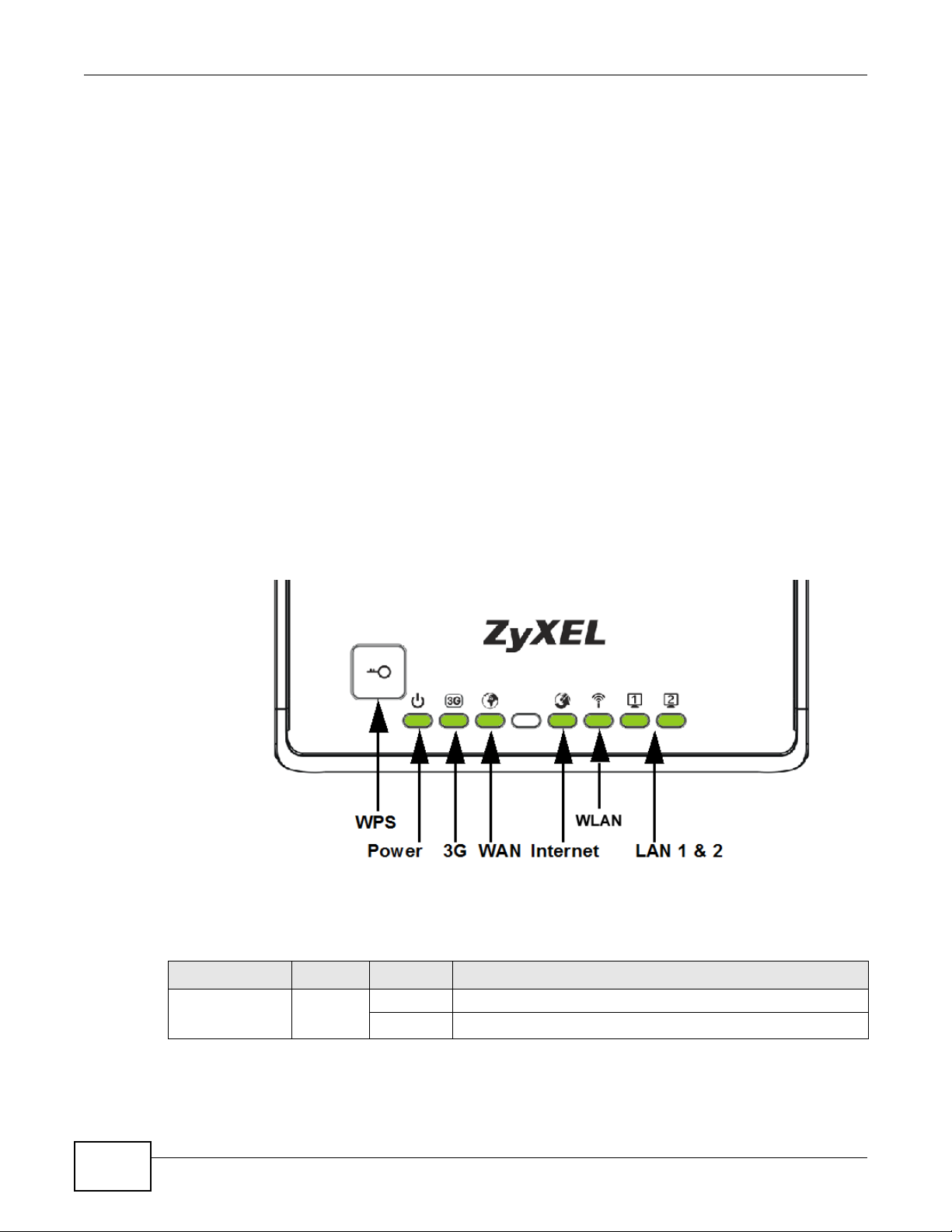
1.5 LEDs
Figure 1 Front Panel
The following table describes the LEDs and the WPS button.
Table 1 Front Panel LEDs and WPS Button
LED COLOR STATUS DESCRIPTION
POWER Green On The NBG4115 is receiving power and functioning properly.
Off The NBG4115 is not receiving power.
16
NBG4115 User’s Guide
Page 17

Chapter 1 Introduction
Table 1 Front Panel LEDs and WPS Button
LED COLOR STATUS DESCRIPTION
WLAN Green On The NBG4115 is ready, but is not sending/receiving data
through the wireless LAN.
Blinking The NBG4115 is sending/receiving data through the wireless
LAN.
The NBG4115 is negotiating a WPS connection with a wireless
client.
Off The wireless LAN is not ready or has failed.
WAN Green On The NBG4115 has a successful 10/100MB WAN connection.
Blinking The NBG4115 is sending/receiving data through the WAN.
Off The WAN connection is not ready, or has failed.
LAN 1-2 Green On The NBG4115 has a successful 10/100MB Ethernet connection.
Blinking The NBG4115 is sending/receiving data through the LAN.
Off The LAN is not connected.
3G Green On The NBG4115 has a 3G card installed and is communicating with
routers.
Blinking The NBG4115 is transmitting and/or receiving data from routers
through an installed 3G card.
Off There is no 3G card installed.
Internet Green On The NBG4115 has received an IP address through either the
WAN or WLAN interface and can connect to the Internet.
Off The NBG4115 has not received an IP address through either the
WPS Button Press this button for 1 second to set up a wireless connection via WiFi Protected Setup
with another WPS-enabled client. You must press the WPS button on the client side within
120 seconds for a successful connection.
WAN or WLAN interface and as such cannot connect to the
Internet.
1.6 The WPS Button
Your NBG4115 supports WiFi Protected Setup (WPS), which is an easy way to set up a secure
wireless network. WPS is an industry standard specification, defined by the WiFi Alliance.
WPS allows you to quickly set up a wireless network with strong security, without having to
configure security settings manually. Each WPS connection works between two devices. Both
devices must support WPS (check each device’s documentation to make sure).
Depending on the devices you have, you can either press a button (on the device itself, or in its
configuration utility) or enter a PIN (a unique Personal Identification Number that allows one device
to authenticate the other) in each of the two devices. When WPS is activated on a device, it has two
minutes to find another device that also has WPS activated. Then, the two devices connect and set
up a secure network by themselves.
For more information on using WPS, see Section 6.4 on page 65.
NBG4115 User’s Guide
17
Page 18
Chapter 1 Introduction
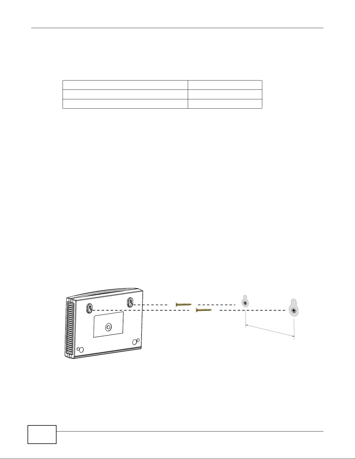
1.7 W all Mounting
You may need screw anchors if mounting on a concrete or brick wall.
Table 2 Wall Mounting Information
Distance between holes 8.8 cm
M4 Screws Two
Screw anchors (optional) Two
1 Select a position free of obstructions on a wall strong enough to hold the weight of the
device.
2 Mark two holes on the wall at the appropriate distance apart for the screws.
Be careful to avoid damaging pipes or cables located inside the wall
when drilling holes for the screws.
3 If using screw anchors, drill two holes for the screw anchors into the wall. Push the
anchors into the full depth of the holes, then insert the screws into the anchors. Do not
insert the screws all the way in - leave a small gap of about 0.5 cm.
If not using screw anchors, use a screwdriver to insert the screws into the wall. Do not
insert the screws all the way in - leave a gap of about 0.5 cm.
4 Make sure the screws are fastened well enough to hold the weight of the NBG4115 with
the connection cables.
5 Align the holes on the back of the NBG4115 with the screws on the wall. Hang the
NBG4115 on the screws.
Figure 2 Wall Mounting Example
18
NBG4115 User’s Guide
Page 19
ZyXEL NetUSB Share Center Utility
2.1 Overview
The ZyXEL NetUSB Share Center Utility allows you to work with the USB devices that are connected
directly to the NBG4115 as if they are connected directly to your computer. This allows you to easily
share USB-based devices such as printers, scanners, portable hard disks, MP3 players, faxes, and
digital cameras (to name a few) with all the other people in your home or office as long as they are
connected to the NBG4115 and have the ZyXEL NetUSB Share Center Utility installed.
For information on configuring the USB network sharing function in the Web Configurator, see
Chapter 20 on page 166.
Note: Be sure to install the Share Center Utility (for NetUSB functionality) from the
included disc, or download the latest version from the zyxel.com website.
CHAPTER 2
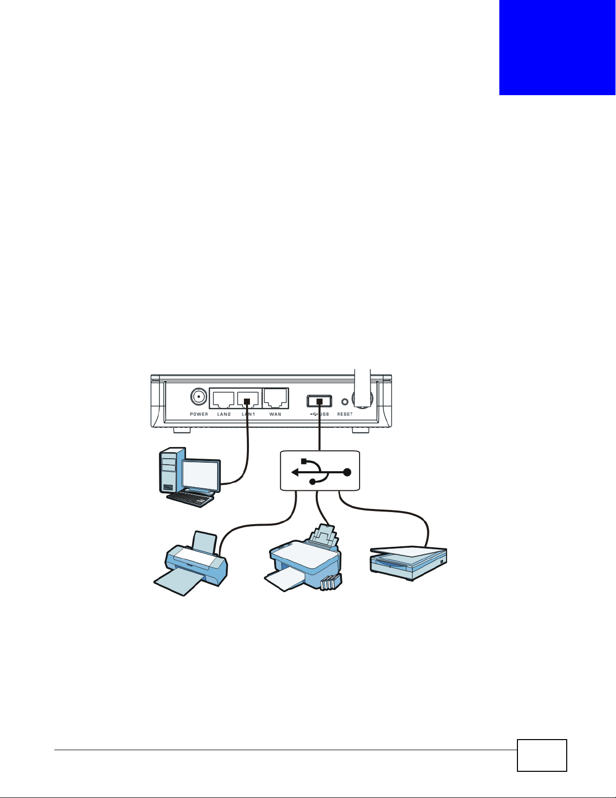
Figure 3 Example of NetUSB
In this example, a USB printer, digital camera, and scanner are all connected to a USB hub. The hub
is in turn connected directly to the NBG4115. Any computer with a ZyXEL NetUSB Share Center
Utility installed on it and which is connected to the NBG4115’s LAN ports can access these devices.
Note: A USB hub attached to the NBG4115 requires its own power adapter.
NBG4115 User’s Guide 19
Page 20
Chapter 2 ZyXEL NetUSB Share Center Utility
2.1.1 Quick Setup
This section shows you how to get started using the ZyXEL NetUSB Share Center Utility.
1 Install the ZyXEL NetUSB Share Center Utility on each computer connected to the NBG4115.
2 Connect a USB device to the USB port on the NBG4115.
Note: If you are connecting multiple devices to the NBG4115, first connect a USB hub to
the NBG4115 then connect your other USB devices to it.
3 Run the ZyXEL NetUSB Share Center Utility to display a list of all connected USB devices, then use
it to connect your computer to them.
2.1.2 Installing ZyXEL NetUSB Share Center Utility
Before you can access USB devices connected to the NBG4115, you must first install the ZyXEL
NetUSB Share Center Utility on any computer on your LAN to which you want to allow access to
these devices.
Note: In order to properly use the ZyXEL NetUSB Share Center Utility with your
NBG4115, ensure that the NBG4115 firmware is version v1.00(BFS.3) or higher.
See Chapter 23 on page 176 for information on updating your device’s firmware.
To install the ZyXEL NetUSB Share Center Utility:
1 Insert the disc that came with your NBG4115 into your computer’s disc drive.
2 Run the Setup program by double-clicking it and then follow the on-screen instructions for
installing it on your computer.
Note: The following operating systems are supported: Windows XP/Vista/7 (32 and 64-bit
versions), Mac OS X 10.4, 10.5 and 10.6.
3 To open the ZyXEL NetUSB Share Center Utility double-click its system tray icon.
20
NBG4115 User’s Guide
Page 21
Chapter 2 ZyXEL NetUSB Share Center Utility
2.2 The ZyXEL NetUSB Share Center Utility
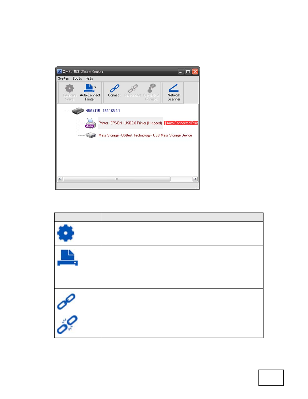
This section describes the ZyXEL NetUSB Share Center Utility main window.
Figure 4 ZyXEL NetUSB Share Center Utility Main Window
The following table describes the icons in this window.
Table 3 ZyXEL NetUSB Share Center Utility Main Window Icons
ICON DESCRIPTION
Configure Server
Click to open the NBG4115’s built-in Web Configurator, which you can use to
set up the NBG4115 (see Chapter 3 on page 29 for details).
Auto-Connect Printer
Click this if you want to automatically connect to the printer each time your
start your computer.
Note: You must first install the appropriate print driver on each computer for
which you intend to use this feature. See the documentation that came
with your printer for instructions on how to do this.
Connect
Select a USB device and then click this button to connect to it. Your computer
can connect to as many USB devices as are connected to the NBG4115.
Disconnect
Select a device to which your computer is connected and then click this
button to disconnect from it.
NBG4115 User’s Guide
21
Page 22
Chapter 2 ZyXEL NetUSB Share Center Utility
Table 3 ZyXEL NetUSB Share Center Utility Main Window Icons (continued)
ICON DESCRIPTION
Request to Connect
Some USB devices may not allow automatic connections over the network. If
so, select the device in question and click this button to issue a request to
connect to it.
Network Scanner
Click this to open the scanner options on your computer for working with a
scanner connected to the network.
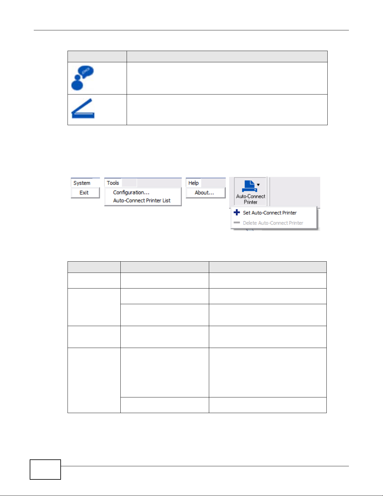
2.2.1 The Menus
This section describes the utility’s menus.
Figure 5 ZyXEL NetUSB Share Center Utility Menus
The following table describes the menus in this screen.
Table 4 ZyXEL NetUSB Share Center Utility Main Screen Menus
MENU ITEM DESCRIPTION
System Exit This closes the ZyXEL NetUSB Share Center
Utility.
Tools Configuration This opens the ZyXEL NetUSB Share Center
Auto-Connect Printer List This opens the list window that displays all
Help About This opens the about window, which
Auto-Connect
Printer
Set Auto-Connect Printer This sets the selected printer to ‘auto-
Utility configuration window.
of the printing devices connected to the
NBG4115.
provides information of the utility software
and driver versions.
connect’, meaning your computer will always
connect to the printer over the network.
Note: You first must install the appropriate
drivers for the printer that you intend
to use.
Delete Auto-Connect Printer This removes the auto-connect option from
the selected printer.
22
NBG4115 User’s Guide
Page 23
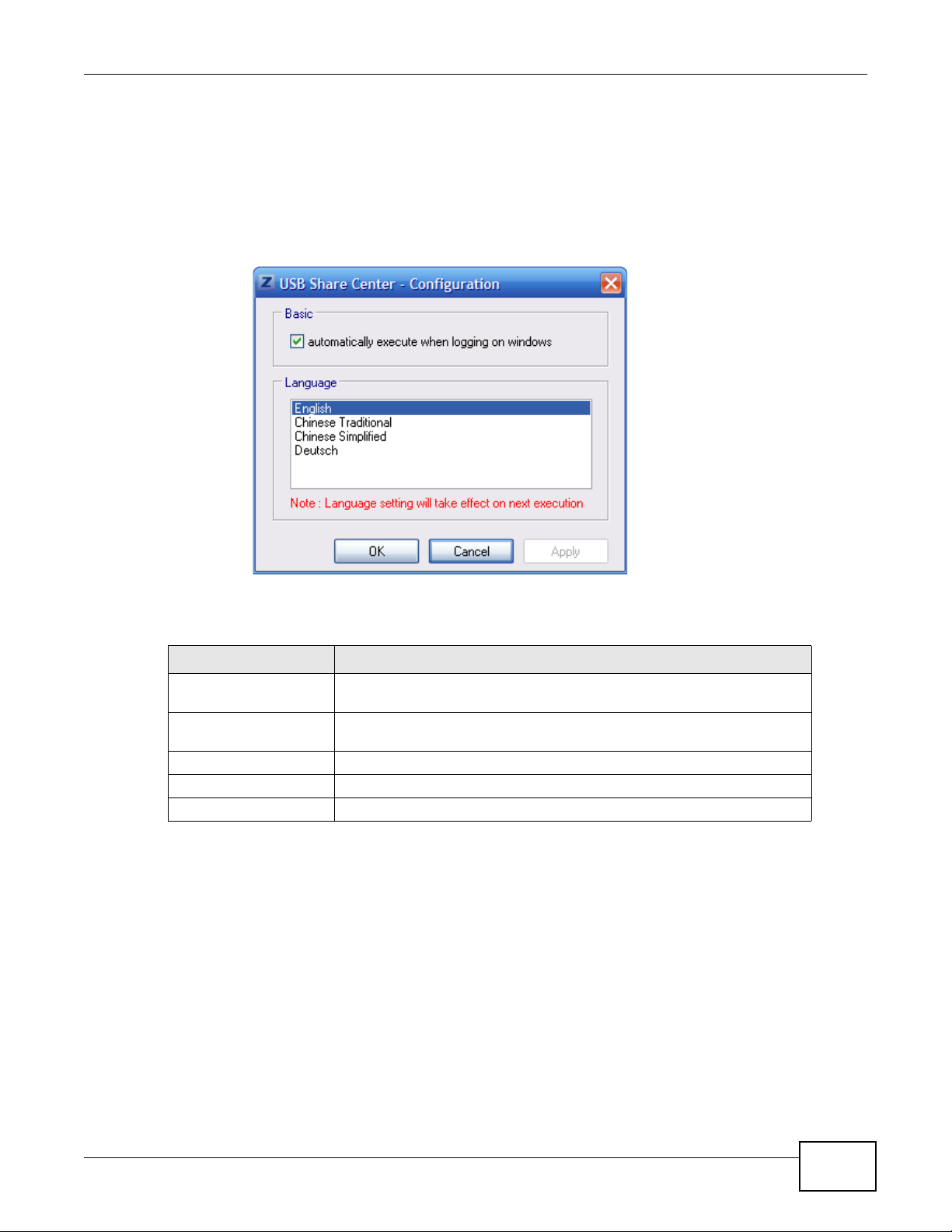
2.2.2 The Share Center Configuration Window
This section describes the utility’s configuration window, which allows you to set certain options for
the utility. These options do not apply to the USB devices connected to the NBG4115.
You can open it by clicking the Tools > Configuration menu command.
Figure 6 ZyXEL NetUSB Share Center Utility Configuration Window
Chapter 2 ZyXEL NetUSB Share Center Utility
The following table describes the labels in this window.
Table 5 ZyXEL NetUSB Share Center Utility Configuration Window
LABEL DESCRIPTION
Basic Select this to run the utilty automatically when you log into or start up
Windows.
Language Select a language for the ZyXEL NetUSB Share Center Utility. You must
restart the utility for the change to take effect.
OK Click this to save your changes and close the window.
Cancel Click this cancel to close the window without saving.
Apply Click this to save your changes without closing the window.
NBG4115 User’s Guide
23
Page 24
Chapter 2 ZyXEL NetUSB Share Center Utility
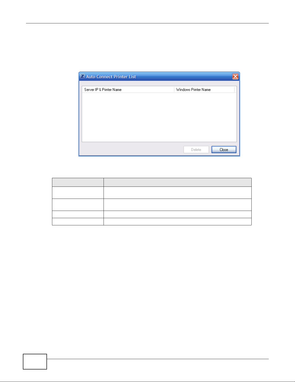
2.2.3 The Auto-Connect Printer List Window
This section describes the utility’s auto-connect printer list window. You can open it by clicking the
Tools > Auto-Connect Printer List menu command.
Figure 7 ZyXEL NetUSB Share Center Utility Auto-Connect Printer List Window
The following table describes the labels in this screen.
Table 6 ZyXEL NetUSB Share Center Utility Auto-Connect Printer List Window
LABEL DESCRIPTION
Server IP & Printer
Name
Windows Printer Name Displays a corresponding list of Windows printer names connected to this
Delete Select an printer from the list and click this to remove it.
Close Click this to close the window.
Displays a list of print server IPs and printer names connected to this
NBG4115.
devices listed in the other list.
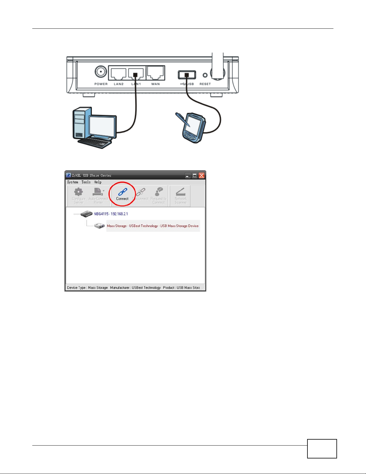
2.3 Manually Connecting to USB Devices
This example shows you how to connect to a USB device over your NBG4115 network. Makes sure
that you have first installed the ZyXEL NetUSB Share Center Utility on the computer to which you
want to connect the USB devices.
Note: If you do this with a USB printer but do not yet have the print driver installed you
will be prompted to install one by the Windows New Hardware Wizard.
24
NBG4115 User’s Guide
Page 25
Chapter 2 ZyXEL NetUSB Share Center Utility
1 Connect a USB device to the NBG4115.
2 In the ZyXEL NetUSB Share Center Utility, select the device and click Connect.
NBG4115 User’s Guide
25
Page 26
Chapter 2 ZyXEL NetUSB Share Center Utility
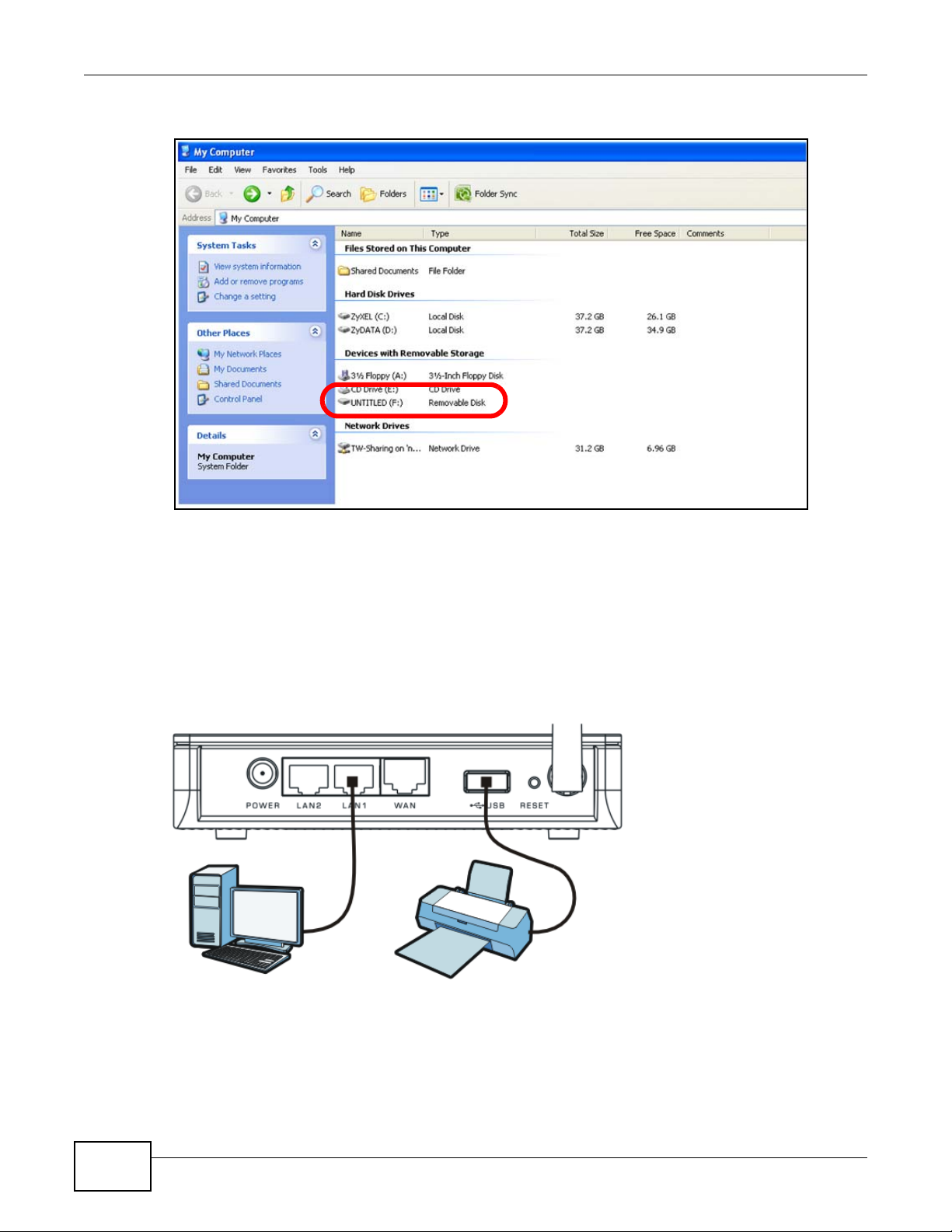
3 The device mounts on your system.
2.4 Automatically Connecting to a USB Printer
This example shows you how to set your computer to automatically connect to a shared USB printer
over your NBG4115 network each time you log into your computer. Makes sure that you have first
installed the ZyXEL NetUSB Share Center Utility.
1 Connect a USB printer to the NBG4115.
26
NBG4115 User’s Guide
Page 27
Chapter 2 ZyXEL NetUSB Share Center Utility
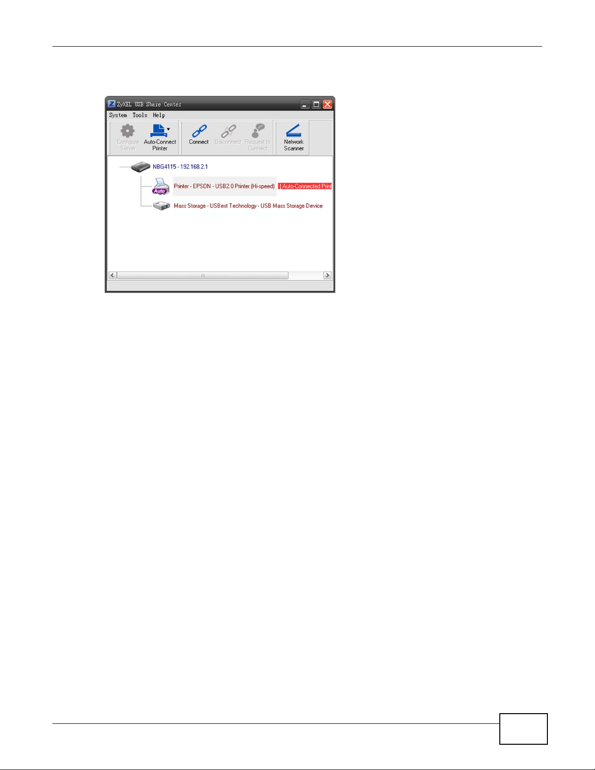
2 Open the ZyXEL Sharing Center Utilit y on the computer that you want to use to connect to the
printer.
Click the Connect button. You may be prompted to install a printer driver or to configure other
settings.
3 Finally, click the Auto-Connect Printer menu and select Set Auto-Connect Printer from the
menu.
NBG4115 User’s Guide
27
Page 28

Chapter 2 ZyXEL NetUSB Share Center Utility
28
NBG4115 User’s Guide
Page 29

3.1 Overview
This chapter describes how to access the NBG4115 Web Configurator and provides an overview of
its screens.
The Web Configurator is an HTML-based management interface that allows easy setup and
management of the NBG4115 via Internet browser. Use Internet Explorer 6.0 and later or Netscape
Navigator 7.0 and later versions or Safari 2.0 or later versions. The recommended screen resolution
is 1024 by 768 pixels.
In order to use the Web Configurator you need to allow:
• Web browser pop-up windows from your device. Web pop-up blocking is enabled by default in
Windows XP SP (Service Pack) 2.
• JavaScripts (enabled by default).
• Java permissions (enabled by default).
CHAPTER 3
The Web Configurator
Refer to the Troubleshooting chapter to see how to make sure these functions are allowed in
Internet Explorer.
3.2 Accessing the Web Configurator
1 Make sure your NBG4115 hardware is properly connected and prepare your computer or computer
network to connect to the NBG4115 (refer to the Quick Start Guide).
2 Launch your web browser.
3 Type "http://192.168.1.1" as the website address.
Your computer must be in the same subnet in order to access this website address.
4 Type "1234" (default) as the password and click Login. In some versions, the default password
appears automatically - if this is the case, click Login.
NBG4115 User’s Guide 29
Page 30
Chapter 3 The Web Configurator
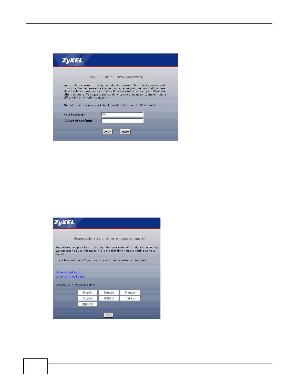
5 You should see a screen asking you to change your password (highly recommended) as shown
next. Type a new password (and retype it to confirm) and click Apply or click Ignore.
Figure 8 Change Password Screen
Note: The management session automatically times out when the time period set in the
Administrator Inactivity Timer field expires (default five minutes). Simply log
back into the NBG4115 if this happens.
6 Select the setup mode you want to use.
• Click Go to Wizard Setup to use the Configuration Wizard for basic Internet and Wireless
setup.
• Click Go to Advanced Setup to view and configure all the NBG4115’s settings.
• Select a language to go to the basic Web Configurator in that language. To change to the
advanced configurator see Chapter 25 on page 184.
Figure 9 Selecting the setup mode
30
NBG4115 User’s Guide
Page 31

3.3 Resetting the NBG4115
If you forget your password or IP address, or you cannot access the Web Configurator, you will need
to use the RESET button at the back of the NBG4115 to reload the factory-default configuration
file. This means that you will lose all configurations that you had previously saved, the password
will be reset to “1234” and the IP address will be reset to “192.168.1.1”.
3.3.1 Procedure to Use the Reset Button
1 Make sure the power LED is on.
2 Press the RESET button for longer than 1 second to restart/reboot the NBG4115.
3 Press the RESET button for longer than five seconds to set the NBG4115 back to its factory-default
configurations.
3.4 Navigating the Web Configurator
Chapter 3 The Web Configurator
The following summarizes how to navigate the Web Configurator from the Status screen in Router
Mode and AP Mode.
3.5 The Status Screen in Router Mode
Click on Status. The screen below shows the status screen in Router Mode.
NBG4115 User’s Guide
31
Page 32

Chapter 3 The Web Configurator
(For information on the status screen in AP Mode see Chapter 5 on page 56.)
Figure 10 Web Configurator Status Screen
The following table describes the icons shown in the Status screen.
Table 7 Status Screen Icon Key
ICON DESCRIPTION
Click this icon to open the setup wizard.
Click this icon to view copyright and a link for related product information.
Click this icon at any time to exit the Web Configurator.
Select a number of seconds or None from the drop-down list box to refresh all screen
statistics automatically at the end of every time interval or to not refresh the screen
statistics.
Click this button to refresh the status screen statistics.
32
NBG4115 User’s Guide
Page 33

Chapter 3 The Web Configurator
The following table describes the labels shown in the Status screen.
Table 8 Web Configurator Status Screen
LABEL DESCRIPTION
Device Information
System Name This is the System Name you enter in the Maintenance > System > General
Firmware Version This is the firmware version and the date created.
WAN Information
- SIM Card Status (3G Only) When a 3G USB device is attached to the NBG4115, this provides
- MAC Address This shows the WAN Ethernet adapter MAC Address of your device.
- IP Address This shows the WAN port’s IP address.
- IP Subnet Mask This shows the WAN port’s subnet mask.
- DHCP This shows the WAN port’s DHCP role - Client or None.
LAN Information
- MAC Address This shows the LAN Ethernet adapter MAC Address of your device.
- IP Address This shows the LAN port’s IP address.
- IP Subnet Mask This shows the LAN port’s subnet mask.
- DHCP This shows the LAN port’s DHCP role - Server or None.
WLAN Information
- MAC Address This shows the wireless adapter MAC Address of your device.
- Status This shows the current status of the Wireless LAN - On, Off or Off by scheduler.
- Name (SSID) This shows a descriptive name used to identify the NBG4115 in the wireless LAN.
- Channel This shows the channel number which you select manually.
- Operating Channel This shows the channel number which the NBG4115 is currently using over the
- Security Mode This shows the level of wireless security the NBG4115 is using.
- 802.11 Mode This shows the wireless standard.
- WPS This displays Configured when the WPS has been set up.
screen. It is for identification purposes.
information specific to it.
wireless LAN.
This displays Unconfigured if the WPS has not been set up.
Click the status to display Network > Wireless LAN > WPS screen.
System Status
System Up Time This is the total time the NBG4115 has been on.
Current Date/Time This field displays your NBG4115’s present date and time.
System Resource
- CPU Usage This displays what percentage of the NBG4115’s processing ability is currently
- Memory Usage This shows what percentage of the heap memory the NBG4115 is using.
System Setting
- Firewall This shows whether the firewall is active or not.
- Bandwidth
Management
- UPnP This shows whether UPnP is active or not.
used. When this percentage is close to 100%, the NBG4115 is running at full load,
and the throughput is not going to improve anymore. If you want some applications
to have more throughput, you should turn off other applications.
This shows whether bandwidth management is enabled or not.
NBG4115 User’s Guide
33
Page 34

Chapter 3 The Web Configurator
Table 8 Web Configurator Status Screen (continued)
LABEL DESCRIPTION
3G Status
This section displays only when you select the Fixed 3G Router Mode option in the NetUSB > General screen
and/or attach a 3G USB dongle to the USB port.
3G Connection Status This displays the type of the 3G network (such as WCDMA) to which the NBG4115
is connected when the 3G connection is up or No Service when the 3G connection
is down or not activated.
Service Provider This displays the name of your network service provider.
Signal Strength This displays the strength of the signal. The signal strength mainly depends on the
Last Connection Up Time This displays how long the 3G connection has been up.
3G Card Manufacturer This displays the manufacturer of your 3G card.
3G Card Model This displays the model name of your 3G card.
3G Card Firmware
Revision
3G Card IMEI This displays the International Mobile Equipment Number (IMEI) which is the serial
SIM Card IMSI This displays the International Mobile Subscriber Identity (IMSI) stored in the SIM
Interface Status
Interface This displays the NBG4115 port types. The port types are: WAN or 3G Modem,
Status For the 3G, LAN and WAN ports, this field displays Down (line is down) or Up (line
Rate
Rate / Signal
antenna output power and the distance between your NBG4115 and the service
provider’s base station. You can see a signal strength indication even when the
NBG4115 does not have a 3G connection (because the signal is still there even
when the NBG4115 is not using it).
This displays the version of the firmware currently used in the 3G card.
number of the 3G wireless card. IMEI is a unique 15-digit number used to identify a
mobile device.
(Subscriber Identity Module) card. The SIM card is installed in a mobile device and
used for authenticating a customer to the carrier network. IMSI is a unique 15-digit
number used to identify a user on a network.
LAN and WLAN.
is up or connected).
For the WLAN, it displays Up when the WLAN is enabled or Down when the WLAN
is disabled.
For the LAN ports, this displays the port speed and duplex setting or N/A when the
line is disconnected.
For the WAN port, it displays the port speed and duplex setting if you’re using
Ethernet encapsulation and Idle (line (ppp) idle), Dial (starting to trigger a call)
and Drop (dropping a call) if you're using PPPoE or PPTP encapsulation. This field
displays N/A when the line is disconnected.
For the 3G port, it displays the current data rate if the 3G connection is up and N/
A when the 3G connection is down. It also displays the strength of the signal.
For the WLAN, it displays the maximum transmission rate when the WLAN is
enabled and N/A
Summary
DHCP Table Use this screen to view current DHCP client information.
Packet Statistics Use this screen to view port status and packet specific statistics.
WLAN Station Status Use this screen to view the wireless stations that are currently associated to the
NBG4115.
34
when the WLAN is disabled.
NBG4115 User’s Guide
Page 35

3.5.1 Navigation Panel
Use the sub-menus on the navigation panel to configure NBG4115 features.
The following table describes the sub-menus.
Table 9 Screens Summary
LINK TAB FUNCTION
Status This screen shows the NBG4115’s general device, system
Network
Wireless LAN General Use this screen to configure wireless LAN.
WAN Internet
LAN IP Use this screen to configure LAN IP address and subnet
Chapter 3 The Web Configurator
and interface status information. Use this screen to access
the wizard, and summary statistics tables.
MAC Filter Use the MAC filter screen to configure the NBG4115 to block
access to devices or block the devices from accessing the
NBG4115.
Advanced This screen allows you to configure advanced wireless
settings.
QoS Use this screen to configure Wi-Fi Multimedia Quality of
Service (WMM QoS). WMM QoS allows you to prioritize
wireless traffic according to the delivery requirements of
individual services.
WPS Use this screen to configure WPS.
WPS Station Use this screen to add a wireless station using WPS.
Scheduling Use this screen to schedule the times the Wireless LAN is
enabled.
This screen is not available when you select the Fixed 3G
Connection
General This screen is available only when you select the Fixed 3G
WAN1 This screen is available only when you select the Fixed 3G
3G(WAN2) This screen is available only when you select the Fixed 3G
Advanced Use this screen to configure other advanced properties.
Router Mode option in the NetUSB > General screen. Use
this screen to configure ISP parameters, WAN IP address
assignment, DNS servers and the WAN MAC address.
Router Mode option in the NetUSB > General screen.
Use this screen to configure WAN priority, the action the
NBG4115 takes after the primary WAN interface fails, and
connection test settings.
Router Mode option in the NetUSB > General screen.
Use this screen to configure the WAN1 connection for
Internet access.
Router Mode option in the NetUSB > General screen.
Use this screen to configure the 3G WAN2 connection for
Internet access.
mask.
NBG4115 User’s Guide
35
Page 36

Chapter 3 The Web Configurator
Table 9 Screens Summary
LINK TAB FUNCTION
DHCP Server General Use this screen to enable the NBG4115’s DHCP server.
NAT General Use this screen to enable NAT.
DDNS General Use this screen to set up dynamic DNS.
Security
Firewall General Use this screen to activate/deactivate the firewall.
Content Filter Filter Use this screen to block certain web features and sites
Management
Static Route IP Static Route Use this screen to configure IP static routes.
Bandwidth
Management
Remote MGMT WWW Use this screen to configure through which interface(s) and
UPnP General Use this screen to enable UPnP on the NBG4115.
WOL General Use this screen to enable Wake on LAN to remotely turn on a
NetUSB General Use this screen to configure how the NBG4115 uses 3G
Maintenance
System General Use this screen to view and change administrative settings
Logs View Log Use this screen to view the logs for the categories that you
Tools Firmware Use this screen to upload firmware to your NBG4115.
Advanced Use this screen to assign IP addresses to specific individual
computers based on their MAC addresses and to have DNS
servers assigned by the DHCP server.
Client List Use this screen to view current DHCP client information and
to always assign an IP address to a MAC address (and host
name).
Application Use this screen to configure servers behind the NBG4115.
Advanced Use this screen to change your NBG4115’s port triggering
settings.
Services This screen shows a summary of the firewall rules, and
allows you to edit/add a firewall rule.
containing certain keywords in the URL.
General Use this screen to use pre-configured bandwidth
management profiles for how your NBG4115 manages
incoming and outgoing data.
Advanced Use this screen to create your own bandwidth management
profile for how your NBG4115 manages incoming and
outgoing data.
from which IP address(es) users can use HTTP to manage
the NBG4115.
device on the local network.
wireless access.
such as system and domain names, password and inactivity
timer.
Time Setting Use this screen to change your NBG4115’s time and date.
selected.
Configuration Use this screen to backup and restore the configuration or
reset the factory defaults to your NBG4115.
Restart This screen allows you to reboot the NBG4115 without
turning the power off.
36
NBG4115 User’s Guide
Page 37

Table 9 Screens Summary
LINK TAB FUNCTION
Sys OP Mode General This screen allows you to select whether your device acts as
Language Language This screen allows you to select the language you prefer.
3.5.2 Summary: DHCP Table
DHCP (Dynamic Host Configuration Protocol, RFC 2131 and RFC 2132) allows individual clients to
obtain TCP/IP configuration at start-up from a server. You can configure the NBG4115’s LAN as a
DHCP server or disable it. When configured as a server, the NBG4115 provides the TCP/IP
configuration for the clients. If DHCP service is disabled, you must have another DHCP server on
that network, or else the computer must be manually configured.
Click the DHCP Table (Details...) hyperlink in the Status screen. Read-only information here
relates to your DHCP status. The DHCP table shows current DHCP client information (including IP
Address, Host Name and MAC Address) of all network clients using the NBG4115’s DHCP server.
Figure 11 Summary: DHCP Table
Chapter 3 The Web Configurator
a Router or a Access Point.
The following table describes the labels in this screen.
Table 10 Summary: DHCP Table
LABEL DESCRIPTION
# This is the index number of the host computer.
IP Address This field displays the IP address relative to the # field listed above.
Host Name This field displays the computer host name.
MAC Address This field shows the MAC address of the computer with the name in the Host Name
field.
Every Ethernet device has a unique MAC (Media Access Control) address which
uniquely identifies a device. The MAC address is assigned at the factory and consists
of six pairs of hexadecimal characters, for example, 00:A0:C5:00:00:02.
Refresh Click Refresh to renew the screen.
NBG4115 User’s Guide
37
Page 38

Chapter 3 The Web Configurator
3.5.3 Summary: Packet Statistics
Click the Packet Statistics (Details...) hyperlink in the Status screen. Read-only information
here includes port status, packet specific statistics and the "system up time". The Poll Interval(s)
field is configurable and is used for refreshing the screen.
Figure 12 Summary: Packet Statistics
The following table describes the labels in this screen.
Table 11 Summary: Packet Statistics
LABEL DESCRIPTION
Port This is the NBG4115’s port type.
Status For the LAN ports, this displays the port speed and duplex setting or Down
when the line is disconnected.
For the WAN port, it displays the port speed and duplex setting if you’re using
Ethernet encapsulation and Idle (line (ppp) idle), Dial (starting to trigger a
call) and Drop (dropping a call) if you're using PPPoE or PPTP encapsulation.
This field displays Down when the line is disconnected.
For the WLAN, it displays the maximum transmission rate when the WLAN is
enabled and Down when the WLAN is disabled.
TxPkts This is the number of transmitted packets on this port.
RxPkts This is the number of received packets on this port.
Collisions This is the number of collisions on this port.
Tx B/s This displays the transmission speed in bytes per second on this port.
Rx B/s This displays the reception speed in bytes per second on this port.
System Up Time This is the total time the NBG4115 has been on.
Poll Interval(s) Enter the time interval for refreshing statistics in this field.
Set Interval Click this button to apply the new poll interval you entered in the Poll
Interval(s) field.
Stop Click Stop to stop refreshing statistics.
3.5.4 Summary: WLAN Station Status
Click the WLAN Station Status (Details...) hyperlink in the Status screen. View the wireless
stations that are currently associated to the NBG4115 in the Association List. Association means
that a wireless client (for example, your network or computer with a wireless network card) has
38
NBG4115 User’s Guide
Page 39

Chapter 3 The Web Configurator
connected successfully to the AP (or wireless router) using the same SSID, channel and security
settings.
Figure 13 Summary: Wireless Association List
The following table describes the labels in this screen.
Table 12 Summary: Wireless Association List
LABEL DESCRIPTION
# This is the index number of an associated wireless station.
MAC Address This field displays the MAC address of an associated wireless station.
Association Time This field displays the time a wireless station first associated with the
NBG4115’s WLAN network.
Refresh Click Refresh to reload the list.
NBG4115 User’s Guide
39
Page 40

Chapter 3 The Web Configurator
40
NBG4115 User’s Guide
Page 41

4.1 Overview
This chapter provides information on the wizard setup screens in the Web Configurator.
4.2 Wizard Setup
The Web Configurator’s wizard setup helps you configure your device to access the Internet. Refer
to your ISP (Internet Service Provider) checklist in the Quick Start Guide to know what to enter in
each field. Leave a field blank if you don’t have that information.
1 After you access the NBG4115 Web Configurator, click the Go to Wizard setup hyperlink.
CHAPTER 4
Connection Wizard
You can click Go to Advanced setup hyperlink to skip this wizard setup and configure basic or
advanced features accordingly.
Figure 14 Select Wizard or Advanced Mode
NBG4115 User’s Guide 41
Page 42

Chapter 4 Connection Wizard
2 Choose a language by clicking on the language’s button. The screen will update. Click the Next
button to proceed to the next screen.
Figure 15 Select a Language
3 Read the on-screen information and click Next.
Figure 16 Welcome to the Connection Wizard
4.3 STEP 1: System Information
System Information contains administrative and system-related information.
4.3.1 System Name
System Name is for identification purposes. However, because some ISPs check this name you
should enter your computer's "Computer Name".
• In Windows 2000, click Start > Settings > Control Panel and then double-click System. Click
the Network Identification tab and then the Properties button. Note the entry for the
Computer name field and enter it as the System Name.
• In Windows XP, click Start > My Computer > View system information and then click the
Computer Name tab. Note the entry in the Full computer name field and enter it as the
NBG4115 System Name.
4.3.2 Domain Name
The Domain Name entry is what is propagated to the DHCP clients on the LAN. If you leave this
blank, the domain name obtained by DHCP from the ISP is used. While you must enter the host
name (System Name) on each individual computer, the domain name can be assigned from the
NBG4115 via DHCP.
42
NBG4115 User’s Guide
Page 43

Chapter 4 Connection Wizard
Click Next to configure the NBG4115 for Internet access.
Figure 17 Wizard Step 1: System Information
The following table describes the labels in this screen.
Table 13 Wizard Step 1: System Information
LABEL DESCRIPTION
System Name System Name is a unique name to identify the NBG4115 in an Ethernet network.
Domain Name Type the domain name (if you know it) here. If you leave this field blank, the ISP
Back Click Back to display the previous screen.
Next Click Next to proceed to the next screen.
Exit Click Exit to close the wizard screen without saving.
Enter a descriptive name. This name can be up to 30 alphanumeric characters long.
Spaces are not allowed, but dashes "-" and underscores "_" are accepted.
may assign a domain name via DHCP. The domain name entered by you is given
priority over the ISP assigned domain name.
4.4 STEP 2: Wireless LAN
Set up your wireless LAN using the following screen.
Figure 18 Wizard Step 2: Wireless LAN
NBG4115 User’s Guide
43
Page 44

Chapter 4 Connection Wizard
The following table describes the labels in this screen.
Table 14 Wizard Step 2: Wireless LAN
LABEL DESCRIPTION
Name (SSID) Enter a descriptive name (up to 32 printable 7-bit ASCII characters) for the wireless
Security Select a Security level from the drop-down list box.
Channel
Selection
Back Click Back to display the previous screen.
Next Click Next to proceed to the next screen.
Exit Click Exit to close the wizard screen without saving.
LAN.
If you change this field on the NBG4115, make sure all wireless stations use the
same SSID in order to access the network.
Choose Auto (WPA2-PSK) to have the NBG4115 generate a pre-shared key
automatically. After you click Next a screen pops up displaying the generated preshared key. Write down the key for use later when connecting other wireless devices
to your network. Click OK to continue.
Choose None to have no wireless LAN security configured. If you do not enable any
wireless security on your NBG4115, your network is accessible to any wireless
networking device that is within range. If you choose this option, skip directly to
Section 4.5 on page 45.
Choose Extend (WPA-PSK or WPA2-PSK) security to configure a Pre-Shared Key.
Choose this option only if your wireless clients support WPA-PSK or WPA2-PSK
respectively. If you choose this option, skip directly to Section 4.4.1 on page 44.
The range of radio frequencies used by IEEE 802.11b/g/n wireless devices is called a
channel. The device will automatically select the channel with the least interference.
Note: The wireless stations and NBG4115 must use the same SSID, channel ID, WPA-PSK
(if WPA-PSK is enabled) or WPA2-PSK (if WPA2-PSK is enabled) for wireless
communication.
4.4.1 Extend (WPA-PSK or WPA2-PSK) Security
Choose Extend (WPA-PSK) or Exten d (WPA2-PSK) security in the Wireless LAN setup screen to
set up a Pre-Shared Key.
Figure 19 Wizard Step 2: Extend (WPA-PSK or WPA2-PSK) Security
44
NBG4115 User’s Guide
Page 45

The following table describes the labels in this screen.
Table 15 Wizard Step 2: Extend (WPA-PSK or WPA2-PSK) Security
LABEL DESCRIPTION
Pre-Shared
Key
Back Click Back to display the previous screen.
Next Click Next to proceed to the next screen.
Exit Click Exit to close the wizard screen without saving.
Type from 8 to 63 case-sensitive ASCII or HEX characters. You can set up the most
secure wireless connection by configuring WPA in the wireless LAN screens. You need
to configure an authentication server to do this.
4.5 STEP 3: Internet Configuration
The NBG4115 offers four Internet connection types. They are Ethernet, PPP over Ethernet,
PPTP or Mobile 3G. The wizard attempts to detect which WAN connection type you are using. If
the wizard does not detect a connection type, you must select one from the drop-down list box.
If you have an always-on connection, most likely you should use Ethernet. If your connection
requires a user name and password to authenticate your connection, then choose either PPPoE or
PPTP. Finally, if you are using a USB-based 3G device, select the Mobile 3G option.
Chapter 4 Connection Wizard
Note: When you select Mobile 3G, then all WAN connections are made through this.
Check with your ISP to make sure you use the correct type.
This wizard screen varies according to the connection type that you select.
Figure 20 Wizard Step 3: ISP Parameters.
The following table describes the labels in this screen,
Table 16 Wizard Step 3: ISP Parameters
CONNECTION TYPE DESCRIPTION
Ethernet Select the Ethernet option when the WAN port is used as a regular
Ethernet.
PPPoE
Select the PPP over Ethernet option for a dial-up connection. If your ISP
gave you an IP address and/or subnet mask, then select PPTP.
NBG4115 User’s Guide
45
Page 46

Chapter 4 Connection Wizard
Table 16 Wizard Step 3: ISP Parameters
CONNECTION TYPE DESCRIPTION
PPTP Select the PPTP option for a dial-up connection.
Mobile 3G Select the Mobile 3G option for a USB 3G connection.
4.5.1 Ethernet Connection
Choose Ethernet when the WAN port is used as a regular Ethernet. Continue to Section 4.5.5 on
page 50.
Figure 21 Wizard Step 3: Ethernet Connection
4.5.2 PPPoE Connection
Point-to-Point Protocol over Ethernet (PPPoE) functions as a dial-up connection. PPPoE is an IETF
(Internet Engineering Task Force) standard specifying how a host personal computer interacts with
a broadband modem (for example DSL, cable, wireless, etc.) to achieve access to high-speed data
networks.
For the service provider, PPPoE offers an access and authentication method that works with existing
access control systems (for instance, RADIUS).
One of the benefits of PPPoE is the ability to let end users access one of multiple network services,
a function known as dynamic service selection. This enables the service provider to easily create
and offer new IP services for specific users.
Operationally, PPPoE saves significant effort for both the subscriber and the ISP/carrier, as it
requires no specific configuration of the broadband modem at the subscriber’s site.
46
NBG4115 User’s Guide
Page 47

Chapter 4 Connection Wizard
By implementing PPPoE directly on the NBG4115 (rather than individual computers), the computers
on the LAN do not need PPPoE software installed, since the NBG4115 does that part of the task.
Furthermore, with NAT, all of the LAN's computers will have Internet access.
Figure 22 Wizard Step 3: PPPoE Connection
The following table describes the labels in this screen.
Table 17 Wizard Step 3: PPPoE Connection
LABEL DESCRIPTION
ISP Parameter for Internet Access
Connection Type Select the PPP over Ethernet option for a dial-up connection.
Service Name Type the name of your service provider.
User Name Type the user name given to you by your ISP.
Password Type the password associated with the user name above.
Back Click Back to return to the previous screen.
Next Click Next to continue.
Exit Click Exit to close the wizard screen without saving.
4.5.3 PPTP Connection
Point-to-Point Tunneling Protocol (PPTP) is a network protocol that enables transfers of data from a
remote client to a private server, creating a Virtual Private Network (VPN) using TCP/IP-based
networks.
PPTP supports on-demand, multi-protocol, and virtual private networking over public networks,
such as the Internet.
Refer to the appendix for more information on PPTP.
NBG4115 User’s Guide
47
Page 48

Chapter 4 Connection Wizard
Note: The NBG4115 supports one PPTP server connection at any given time.
Figure 23 Wizard Step 3: PPTP Connection
The following table describes the fields in this screen
Table 18 Wizard Step 3: PPTP Connection
LABEL DESCRIPTION
ISP Parameters for Internet Access
Connection Type Select PPTP from the drop-down list box. To configure a PPTP client, you must
configure the User Name and Password fields for a PPP connection and the
PPTP parameters for a PPTP connection.
User Name Type the user name given to you by your ISP.
Password Type the password associated with the User Name above.
PPTP Configuration
Server IP Address Type the IP address of the PPTP server.
Connection ID/
Name
Get automatically
from ISP
Use fixed IP
address
My IP Address Type the (static) IP address assigned to you by your ISP.
My IP Subnet
Mask
Back Click Back to return to the previous screen.
Next Click Next to continue.
Exit Click Exit to close the wizard screen without saving.
Enter the connection ID or connection name in this field. It must follow the
"c:id" and "n:name" format. For example, C:12 or N:My ISP.
This field is optional and depends on the requirements of your ISP.
Select this radio button if your ISP did not assign you a fixed IP address.
Select this radio button, provided by your ISP to give the NBG4115 a fixed,
unique IP address.
Type the subnet mask assigned to you by your ISP (if given).
48
NBG4115 User’s Guide
Page 49

4.5.4 Mobile 3G
Mobile 3G is a set of international “third generation” standards for the sending and receiving of
voice, video, and wireless data in a mobile environment. For the NBG4115, this type of wireless
connection requires a connected 3G-compatible USB device (see the included Quick Start Guide for
installation information), and a 3G account with your local ISP.
Note: When you use Mobile 3G, all WAN connections are made through it.
Figure 24 Wizard Step 3: Mobile 3G Connection
Chapter 4 Connection Wizard
The following table describes the fields in this screen
Table 19 Wizard Step 3: Mobile 3G Connection
LABEL DESCRIPTION
ISP Parameters for Internet Access
Connection Type Select Mobile 3G from the drop-down list box.
PIN Code Enter the 4-digit 3G account PIN code given to you by your ISP.
APN Code Enter the Access Point Name (APN) given to you by your ISP.
Dial Number Enter the phone number that must be dialed in order to login to your 3G
account from the NBG4115.
User Name Type the user name given to you by your ISP.
Password Type the password associated with the User Name above.
Back Click Back to return to the previous screen.
Next Click Next to continue.
Exit Click Exit to close the wizard screen without saving.
NBG4115 User’s Guide
49
Page 50

Chapter 4 Connection Wizard
4.5.5 Your IP Address
The following wizard screen allows you to assign a fixed IP address or give the NBG4115 an
automatically assigned IP address depending on your ISP or network administrator.
Figure 25 Wizard Step 3: Your IP Address
The following table describes the labels in this screen
Table 20 Wizard Step 3: Your IP Address
LABEL DESCRIPTION
Get automatically from
your ISP
Select this option if the ISP or your network administrator did not assign
a static IP address to use for Internet access.
This is the default selection. If you choose this option, skip directly to
Section 4.5.10 on page 53.
Use fixed IP address
provided by your ISP
Back Click Back to return to the previous screen.
Next Click Next to continue.
Exit Click Exit to close the wizard screen without saving.
Select this option if you were assigned a fixed IP address (and DNS
server settings) to use for Internet access
The fixed IP address should be in the same subnet as your broadband
modem or router.
4.5.6 WAN IP Address Assignment
Every computer on the Internet must have a unique IP address. If your networks are isolated from
the Internet, for instance, only between your two branch offices, you can assign any IP addresses
to the hosts without problems. However, the Internet Assigned Numbers Authority (IANA) has
reserved the following three blocks of IP addresses specifically for private networks.
Table 21 Private IP Address Ranges
10.0.0.0 - 10.255.255.255
172.16.0.0 - 172.31.255.255
192.168.0.0 - 192.168.255.255
50
You can obtain your IP address from the IANA, from an ISP or have it assigned by a private
network. If you belong to a small organization and your Internet access is through an ISP, the ISP
can provide you with the Internet addresses for your local networks. On the other hand, if you are
part of a much larger organization, you should consult your network administrator for the
appropriate IP addresses.
NBG4115 User’s Guide
Page 51

Note: Regardless of your particular situation, do not create an arbitrary IP address;
always follow the guidelines above. For more information on address assignment,
please refer to RFC 1597, Address Allocation for Private Internets and RFC 1466,
Guidelines for Management of IP Address Space.
4.5.7 IP Address and Subnet Mask
Similar to the way houses on a street share a common street name, so too do computers on a LAN
share one common network number.
Where you obtain your network number depends on your particular situation. If the ISP or your
network administrator assigns you a block of registered IP addresses, follow their instructions in
selecting the IP addresses and the subnet mask.
If the ISP did not explicitly give you an IP network number, then most likely you have a single user
account and the ISP will assign you a dynamic IP address when the connection is established. The
Internet Assigned Number Authority (IANA) reserved this block of addresses specifically for private
use; please do not use any other number unless you are told otherwise. Let's say you select
192.168.1.0 as the network number; which covers 254 individual addresses, from 192.168.1.1 to
192.168.1.254 (zero and 255 are reserved). In other words, the first three numbers specify the
network number while the last number identifies an individual computer on that network.
Chapter 4 Connection Wizard
Once you have decided on the network number, pick an IP address that is easy to remember, for
instance, 192.168.1.1, for your NBG4115, but make sure that no other device on your network is
using that IP address.
The subnet mask specifies the network number portion of an IP address. Your NBG4115 will
compute the subnet mask automatically based on the IP address that you entered. You don't need
to change the subnet mask computed by the NBG4115 unless you are instructed to do otherwise.
4.5.8 DNS Server Address Assignment
Use DNS (Domain Name System) to map a domain name to its corresponding IP address and vice
versa, for instance, the IP address of www.zyxel.com is 204.217.0.2. The DNS server is extremely
important because without it, you must know the IP address of a computer before you can access
it.
The NBG4115 can get the DNS server addresses in the following ways.
1 The ISP tells you the DNS server addresses, usually in the form of an information sheet, when you
sign up. If your ISP gives you DNS server addresses, enter them in the DNS Server fields in the
Wizard and/or WAN > Internet Connection screen.
2 If the ISP did not give you DNS server information, leave the DNS Server fields set to 0.0.0.0 in
the Wizard screen and/or set to From ISP in the WAN > Internet Connection screen for the
ISP to dynamically assign the DNS server IP addresses.
NBG4115 User’s Guide
51
Page 52

Chapter 4 Connection Wizard
4.5.9 WAN IP and DNS Server Address Assignment
The following wizard screen allows you to assign a fixed WAN IP address and DNS server addresses.
Figure 26 Wizard Step 3: WAN IP and DNS Server Addresses
The following table describes the labels in this screen
Table 22 Wizard Step 3: WAN IP and DNS Server Addresses
LABEL DESCRIPTION
WAN IP Address Assignment
My WAN IP Address Enter your WAN IP address in this field. The WAN IP address should be in
the same subnet as your DSL/Cable modem or router.
My WAN IP Subnet Mask Enter the IP subnet mask in this field.
Gateway IP Address Enter the gateway IP address in this field.
System DNS Server Address Assignment (if applicable)
DNS (Domain Name System) is for mapping a domain name to its corresponding IP address and vice
versa. The DNS server is extremely important because without it, you must know the IP address of a
computer before you can access it. The NBG4115 uses a system DNS server (in the order you specify
here) to resolve domain names for DDNS and the time server.
First DNS Server
Second DNS Server
Back Click Back to return to the previous screen.
Next Click Next to continue.
Exit Click Exit to close the wizard screen without saving.
Enter the DNS server's IP address in the fields provided.
If you do not configure a system DNS server, you must use IP addresses
when configuring DDNS and the time server.
52
NBG4115 User’s Guide
Page 53

4.5.10 WAN MAC Address
Every Ethernet device has a unique MAC (Media Access Control) address. The MAC address is
assigned at the factory and consists of six pairs of hexadecimal characters, for example,
00:A0:C5:00:00:02.
Table 23 Example of Network Properties for LAN Servers with Fixed IP Addresses
Choose an IP address 192.168.1.2-192.168.1.32; 192.168.1.65-192.168.1.254.
Subnet mask 255.255.255.0
Gateway (or default route) 192.168.1.1(NBG4115 LAN IP)
This screen allows users to configure the WAN port's MAC address by either using the NBG4115’s
MAC address, copying the MAC address from a computer on your LAN or manually entering a MAC
address. Once it is successfully configured, the address will be copied to configuration file. It is
advisable to clone the MAC address from a computer on your LAN even if your ISP does not
presently require MAC address authentication.
Figure 27 Wizard Step 3: WAN MAC Address
Chapter 4 Connection Wizard
The following table describes the fields in this screen.
Table 24 Wizard Step 3: WAN MAC Address
LABEL DESCRIPTION
Factory Default Select Factory Default to use the factory assigned default MAC address.
Clone the
computer’s MAC
address
Set WAN MAC
Address
Back Click Back to return to the previous screen.
Next Click Next to continue.
Exit Click Exit to close the wizard screen without saving.
NBG4115 User’s Guide
Select this option and enter the IP address of the computer on the LAN whose
MAC you are cloning. It is advisable to clone the MAC address from a computer
on your LAN even if your ISP does not presently require MAC address
authentication.
Select this option and enter the MAC address you want to use.
53
Page 54

Chapter 4 Connection Wizard
4.6 Connection Wizard Complete
Click Finish to complete the wizard setup.
Figure 28 Connection Wizard Complete
You have successfully set up your NBG4115 to operate on your network and access the Internet.
54
NBG4115 User’s Guide
Page 55

5.1 Overview
A
B
This chapter discusses how to configure settings while your NBG4115 is set to AP Mode. Many
screens that are available in Router Mode are not available in AP Mode.
Note: See Chapter 6 on page 61 for an example of setting up a wireless network in AP
mode.
Use your NBG4115 as an AP if you already have a router or gateway on your network. In this mode
your device bridges a wired network (LAN) and wireless LAN (WLAN) in the same subnet. See the
figure below for an example.
Figure 29 Wireless Internet Access in AP Mode
CHAPTER 5
AP Mode
5.2 Setting your NBG4115 to AP Mode
1 Log into the Web Configurator if you haven’t already. See the Quick start Guide for instructions on
how to do this.
NBG4115 User’s Guide 55
Page 56

Chapter 5 AP Mode
2 To set your NBG4115 to AP Mode, go to Maintenance > Sys OP Mode > General and select
Access Point.
Figure 30 Maintenance > Sys OP Mode > General
3 A pop-up appears providing information on this mode. Click OK in the pop-up message window.
(See Section 24.2 on page 182 for more information on the pop-up.) Click Apply. Your NBG4115 is
now in AP Mode.
Note: You have to log in to the Web Configurator again when you change modes.
5.3 The Status Screen in AP Mode
Click on Status. The screen below shows the status screen in AP Mode.
Figure 31 Status: AP Mode
56
NBG4115 User’s Guide
Page 57

The following table describes the labels shown in the Status screen.
Table 25 Web Configurator Status Screen
LABEL DESCRIPTION
Device Information
System Name This is the System Name you enter in the Maintenance > System > General
screen. It is for identification purposes.
Firmware Version This is the firmware version and the date created.
LAN Information
- MAC Address This shows the LAN Ethernet adapter MAC Address of your device.
- IP Address This shows the LAN port’s IP address.
- IP Subnet Mask This shows the LAN port’s subnet mask.
- DHCP This shows the LAN port’s DHCP role - None.
WLAN Information
- MAC Address This shows the wireless adapter MAC Address of your device.
- Status This shows the current status of the Wireless LAN - On, Off or Off by schedule r.
- Name (SSID) This shows a descriptive name used to identify the NBG4115 in the wireless LAN.
- Channel This shows the channel number which you select manually.
- Operating Channel This shows the channel number which the NBG4115 is currently using over the
wireless LAN.
- Security Mode This shows the level of wireless security the NBG4115 is using.
- 802.11 Mode This shows the IEEE 802.11 standard that the NBG4115 supports. Wireless clients
must support the same standard in order to be able to connect to the NBG4115
- WPS This shows the WPS (WiFi Protected Setup) Status. Click the status to display
Network > Wireless LAN > WPS screen.
System Status
System Up Time This is the total time the NBG4115 has been on.
Current Date/Time This field displays your NBG4115’s present date and time.
System Resource
- CPU Usage This displays what percentage of the NBG4115’s processing ability is currently
used. When this percentage is close to 100%, the NBG4115 is running at full load,
and the throughput is not going to improve anymore. If you want some applications
to have more throughput, you should turn off other applications.
- Memory Usage This shows what percentage of the heap memory the NBG4115 is using.
Interface Status
Interface This displays the NBG4115 port types. The port types are: LAN and WLAN.
Status For the LAN port, this field displays Down (line is down) or Up (line is up or
connected).
Chapter 5 AP Mode
For the WLAN, it displays Up when the WLAN is enabled or Down when the WLAN
is disabled.
Rate For the LAN ports, this displays the port speed and duplex setting or N/A when the
line is disconnected.
For the WLAN, it displays the maximum transmission rate when the WLAN is
enabled and N/A when the WLAN is disabled.
Summary
NBG4115 User’s Guide
57
Page 58

Chapter 5 AP Mode
Table 25 Web Configurator Status Screen (continued)
LABEL DESCRIPTION
Packet Statistics Use this screen to view port status and packet specific statistics.
WLAN Station Status Use this screen to view the wireless stations that are currently associated to the
NBG4115.
5.3.1 Navigation Panel
Use the menu in the navigation panel to configure NBG4115 features in AP Mode.
The following screen and table show the features you can configure in AP Mode.
Figure 32 Menu: AP Mode
The following table describes the sub-menus.
Table 26 Screens Summary
LINK TAB FUNCTION
Status This screen shows the NBG4115’s general device, system and
interface status information. Use this screen to access the wizard,
and summary statistics tables.
Network
Wireless LAN General Use this screen to configure wireless LAN.
MAC Filter Use the MAC filter screen to configure the NBG4115 to block
access to devices or block the devices from accessing the
NBG4115.
Advanced This screen allows you to configure advanced wireless settings.
QoS Use this screen to configure Wi-Fi Multimedia Quality of Service
WPS Use this screen to configure WPS.
WPS Station Use this screen to add a wireless station using WPS.
Scheduling Use this screen to schedule the times the Wireless LAN is enabled.
LAN IP Use this screen to configure LAN IP address and subnet mask or
Maintenance
(WMM QoS). WMM QoS allows you to prioritize wireless traffic
according to the delivery requirements of individual services.
to get the LAN IP address from a DHCP server.
58
NBG4115 User’s Guide
Page 59

Table 26 Screens Summary
LINK TAB FUNCTION
System General Use this screen to view and change administrative settings such
Time Setting Use this screen to change your NBG4115’s time and date.
Logs View Log Use this screen to view the logs for the categories that you
Tools Firmware Use this screen to upload firmware to your NBG4115.
Configuration Use this screen to backup and restore the configuration or reset
Restart This screen allows you to reboot the NBG4115 without turning the
Sys OP Mode General This screen allows you to select whether your device acts as a
Language This screen allows you to select the language you prefer.
5.4 LAN Settings
Chapter 5 AP Mode
as system and domain names, password and inactivity timer.
selected.
the factory defaults to your NBG4115.
power off.
Router or a Access Point.
Use this section to configure your LAN settings while in AP Mode.
Click Network > LAN to see the screen below.
Note: If you change the IP address of the NBG4115 in the screen below, you will need to
log into the NBG4115 again using the new IP address.
Figure 33 Network > LAN > IP
The table below describes the labels in the screen.
Table 27 Network > LAN > IP
LABEL DESCRIPTION
Get from DHCP
Server
User Defined
LAN IP
IP Address Type the IP address in dotted decimal notatiion. The default setting is 192.168.1.2.
Select this to let the DHCP server in the gateway assign the NBG4115 IP address.
Select this to give the NBG4115 a static IP address.
If you change the IP address you will have to log in again with the new IP address.
NBG4115 User’s Guide
59
Page 60

Chapter 5 AP Mode
LABEL DESCRIPTION
IP Subnet Mask The subnet mask specifies the network number portion of an IP address. Your
NBG4115 will automatically calculate the subnet mask based on the IP address that
you assign. Unless you are implementing subnetting, use the subnet mask
computed by the NBG4115.
Apply Click Apply to save your changes to the NBG4115.
Reset Click Reset to reload the previous configuration for this screen.
5.5 WLAN and Maintenance Settings
The configuration of wireless and maintenance settings in AP Mode is the same as for Router
Mode.
•See Wireless LAN (77) for information on the configuring your wireless network.
•See System (169), Logs (174), Tools (1 7 6), Sys OP Mode (181) and Language (184) for
information on the configuring your Maintenance settings.
5.6 Logging in while in AP Mode
1 Connect your computer to the LAN port of the NBG4115.
2 The default IP address of the NBG4115 is “192.168.1.2”. In this case, your computer must have an
IP address in the range between “192.168.1.3” and “192.168.1.254”.
3 Click Start > Run on your computer in Windows.
4 Type “cmd” in the dialog box.
5 Type “ipconfig” to show your computer’s IP address. If your computer’s IP address is not in the
correct range then see Appendix C on page 215 for information on changing your computer’s IP
address.
6 After you’ve set your computer’s IP address, open a web browser such as Internet Explorer and
type “192.168.1.2” as the web address in your web browser.
See Chapter 6 on page 61 for a tutorial on setting up a network with an AP.
60
NBG4115 User’s Guide
Page 61

6.1 Overview
This chapter provides tutorials for setting up your NBG4115.
6.2 Set Up a 3G Connection
This section shows you how to make a 3G connection with your NBG4115. There are two ways to
set up your 3G options.
1 Use the Wizard, which was introduced in the Quick Start Guide. The wizard is good for getting up
and running in as little time as possible. It allows you to configure the minimum number of options
required to get connected.
CHAPTER 6
Tutorials
2 Use the Web Configurator’s Network options. This is handy because it gives you access to other
options not available in the Wizard, allowing you to have more control over your device.
This tutorial shows you how to do the second one.
You will need the following information, which should be provided by your ISP:
FIELD DESCRIPTION EXAMPLE
PIN Code This is the 4-digit Personal
Identification Number (PIN) for your 3G
device’s SIM card.
APN Code This is the Access Point Name (APN) of
the 3G network to which you intend to
connect.
Dial Number This is the number used to instruct your
3G device to make its data connection
to the 3G network.
User Name This is your account user name. dcmchale
Password This is your account user name’s
password.
To set up a 3G connection:
1234
mobile.p3.cz.co
gprsinternet
*99#
*99***3#
0b1ken@kashiik.org
*****
1 Connect to the Web Configurator, as described in the Quick Start Guide.
NBG4115 User’s Guide 61
Page 62

Chapter 6 Tutorials
2 When presented with the option to choose either Wizard or Advanced, click Go to Advanced
setup.
3 Expand the Network submenu on the navigation pane, then click WAN.
62
NBG4115 User’s Guide
Page 63

Chapter 6 Tutorials
4 From the Connection Type menu, select Mobile 3G then configure your 3G settings when the
screen updates itself.f
5 Click Apply to save your changes, then exit the Web Configurator.
Note: Once you set up and enable a 3G device, all incoming and outgoing network
connections are made through it and not the WAN port on your NBG4115.
6.3 Set Up the NBG4115 for Gaming
Gaming is a very popular online activity, and one that can be extremely bandwidth sensitive. Some
video games may have higher performance expectations than other types of software. As such,
they tend to require more finely tuned Quality of Service (QoS) prioritization. If the data packets
from a game are assigned a lower priority by the NBG4115, then they may take longer to reach
their destination; but if they are given a higher priority, then they should arrive at their destination
marginally faster. This is because Internet servers that rely on QoS to sort packets that are in
transit generally pass higher priority packets on first, while lower priority packets are held back
slightly longer.
When this happens on a single server with a single data packet, your gameplay is not affected.
When it happens over 15 servers from beginning to end with thousands of bytes of data, then the
build up of low-priority latency can become significant. For Massively Multiplayer Online (MMOs)
and First Person Shooters (FPS) (which account for 3-4% of all Internet-related traffic) a latency
difference of even 200 milliseconds is enough to ruin the gaming experience.
Bandwidth management allows you to set up custom parameters on the NBG4115 so that whenever
you play a game, the QoS is automatically upgraded to the highest priority in order to ensure your
game data packets are plucked first from the pool of incoming information and sent on ahead of
lower priority packets.
This tutorial shows you how to set up your NBG4115 for gaming.
NBG4115 User’s Guide
63
Page 64

Chapter 6 Tutorials
1 In the Web Configurator, expand the navigation pane’s Management category and then select
Bandwidth MGMT
2 Select the Advanced tab.
3 Enable the Gaming check box and set its Priority to High.
The following gaming ports are preconfigured on your NBG4115 and are enabled when you select
the ‘gaming’ Service in the Management > Bandwidth MGMT > Advanced screen:
64
Table 28 Preconfigured Gaming Ports
APPLICATION TCP PORTS UDP PORTS
XBox 360 3074, 3390, 3932, 5555 1900, 3776, 7777, 88, 3074
Playstation 80, 443, 5223, 5223 3478, 3479, 3658, 4658
NBG4115 User’s Guide
Page 65

Chapter 6 Tutorials
Table 28 Preconfigured Gaming Ports
APPLICATION TCP PORTS UDP PORTS
Battlenet 40, 6112, 4000, 6113- 6119,
112
MSN Game Zone 6667, 28800-29000 6667, 28800-29000
Note: If you need to customize specific ports, go to the next step. Otherwise, skip ahead
to step 5.
4 To create a custom QoS setting for a specific game, enter the following information in the first
available custom Priority Queue line:
Service: This is the name by which your custom service is labled. It can be anything with the
limitation that it cannot be longer than 10 characters.
Priority: Set this to High.
Specific Port: From the list, select the communication protocol your game uses. In this example,
our game uses TCP/IP so we choose TCP. If you are not sure, then select Both. Enter the starting
port in the first port range box, then enter then last port in the second port range box. For our
game, we used 6112 to 6119.
5 Click Apply to save your changes, then exit the Web Configurator.
6.4 Set Up a Wireless Network with WPS
This section gives you an example of how to set up wireless network using WPS. This example uses
the NBG4115 as the AP and NWD210N as the wireless client which connects to a notebook.
Note: The wireless client must be a WPS-aware device (for example, a WPS USB adapter
or PCI card).
There are two WPS methods for creating a secure connection. This tutorial shows you how to do
both.
• Push Button Configuration (PBC) - create a secure wireless network simply by pressing a
button. See Section 6.4.1 on page 66.This is the easier method.
• PIN Configuration - create a secure wireless network simply by entering a wireless client's PIN
(Personal Identification Number) in the NBG4115’s interface. See Section 6.4.2 on page 67. This
is the more secure method, since one device can authenticate the other.
NBG4115 User’s Guide
65
Page 66

Chapter 6 Tutorials
6.4.1 Push Button Configuration (PBC)
1 Make sure that your NBG4115 is turned on and that it is within range of your computer.
2 Make sure that you have installed the wireless client (this example uses the NWD210N) driver and
utility in your notebook.
3 In the wireless client utility, find the WPS settings. Enable WPS and press the WPS button (Start or
WPS button)
4 Log into NBG4115’s Web Configurator and press the Push Button button in the Network >
Wireless Client > WPS Station screen.
Note: Your NBG4115 has a WPS button located on its panel, as well as a WPS button in its
configuration utility. Both buttons have exactly the same function; you can use one
or the other.
Note: It doesn’t matter which button is pressed first. You must press the second button
within two minutes of pressing the first one.
The NBG4115 sends the proper configuration settings to the wireless client. This may take up to
two minutes. Then the wireless client is able to communicate with the NBG4115 securely.
66
NBG4115 User’s Guide
Page 67

Chapter 6 Tutorials
Wireless Client
Access Point
SECURITY INFO
COMMUNICATION
WITHIN 2 MINUTES
The following figure shows you an example to set up wireless network and security by pressing a
button on both NBG4115 and wireless client (the NWD210N in this example).
Figure 34 Example WPS Process: PBC Method
6.4.2 PIN Configuration
NBG4115 User’s Guide
When you use the PIN configuration method, you need to use both NBG4115’s configuration
interface and the client’s utilities.
1 Launch your wireless client’s configuration utility. Go to the WPS settings and select the PIN method
to get a PIN number.
2 Enter the PIN number to the PIN field in the Network > Wireless LAN > WPS Station screen on
the NBG4115.
3 Click Start buttons (or button next to the PIN field) on both the wireless client utility screen and the
NBG4115’s WPS Station screen within two minutes.
The NBG4115 authenticates the wireless client and sends the proper configuration settings to the
wireless client. This may take up to two minutes. Then the wireless client is able to communicate
with the NBG4115 securely.
67
Page 68

Chapter 6 Tutorials
WITHIN 2 MINUTES
Wireless Client
Access Point
The following figure shows you the example to set up wireless network and security on NBG4115
and wireless client (ex. NWD210N in this example) by using PIN method.
Figure 35 Example WPS Process: PIN Method
6.5 Configure Wireless Security without WPS
1 Open the Wireless LAN > General screen in the AP’s Web Configurator.
2 Make sure the Enable Wireless LAN check box is selected.
68
This example shows you how to configure wireless security settings with the following parameters
on your NBG4115.
SSID SSID_Example3
Channel 6
Security WPA-PSK
(Pre-Shared Key: ThisismyWPA-PSKpre-sharedkey)
Follow the steps below to configure the wireless settings on your NBG4115.
The instructions require that your hardware is connected (see the Quick Start Guide) and you are
logged into the Web Configurator through your LAN connection (see Section 3.2 on page 29).
NBG4115 User’s Guide
Page 69

Chapter 6 Tutorials
3 Enter SSID_Example3 as the SSID and select a channel.
4 Set security mode to WPA-PSK and enter ThisismyWPA-PSKpre-sharedkey in the Pre-Shared
Key field. Click Apply.
Figure 36 Tutorial: Network > Wireless LAN > General
5 Open the Status screen. Verify your wireless and wireless security settings under Device
Information and check if the WLAN connection is up under Interface Status.
Figure 37 Tutorial: Status Screen
NBG4115 User’s Guide
69
Page 70

Chapter 6 Tutorials
6.5.1 Configure Your Notebook
Note: We use the ZyXEL M-302 wireless adapter utility screens as an example for the
wireless client. The screens may vary for different models.
1 The NBG4115 supports IEEE 802.11b, IEEE 802.11g and IEEE 802.11n wireless clients. Make sure
that your notebook or computer’s wireless adapter supports one of these standards.
2 Wireless adapters come with software sometimes called a “utility” that you install on your
computer. See your wireless adapter’s User’s Guide for information on how to do that.
3 After you’ve installed the utility, open it. If you cannot see your utility’s icon on your screen, go to
Start > Programs and click on your utility in the list of programs that appears. The utility displays
a list of APs within range, as shown in the example screen below.
4 Select SSID_Example3 and click Connect.
Figure 38 Connecting a Wireless Client to a Wireless Network t
5 Select WPA-PSK and type the security key in the following screen. Click Next.
Figure 39 Security Settings
70
NBG4115 User’s Guide
Page 71

Chapter 6 Tutorials
6 The Confirm Save window appears. Check your settings and click Save to continue.
Figure 40 Confirm Save
7 Check the status of your wireless connection in the screen below. If your wireless connection is
weak or you have no connection, see the Troubleshooting section of this User’s Guide.
Figure 41 Link Status
If your connection is successful, open your Internet browser and enter http://www.zyxel.com or the
URL of any other web site in the address bar. If you are able to access the web site, your wireless
connection is successfully configured.
6.6 Bandwidth Management
This section shows you how to configure the bandwidth management feature on the NBG4115 to
limit the bandwidth for specific kinds of outgoing traffic. ZyXEL's bandwidth management feature
allows you to specify bandwidth management rules based on an application or subnet.
Use the Management > Bandwidth MGMT > Advanced screen to configure bandwidth
management for your network.
6.6.1 Bandwidth Management by Application
For this example, your company’s customer support department wants to prioritize VoIP, e-mail and
MSN Messenger services.
NBG4115 User’s Guide
71
Page 72

Chapter 6 Tutorials
In the Priority Queue table, VoIP and e-mail services are already pre-defined. However, you still
need to add MSN Messenger in the list (refer to Section 6.6.2 on page 72).
In the following screen, you set the priorities for VoIP and e-mail.
Figure 42 Tutorial: Priority Queue
Click Enable for the VoIP (SIP) service and set priority to High. Do the same for E-mail. For the
rest of the applications, click Enable if you need these services and set the priority to Low.
Note: You can also leave the Enable field blank for the rest of the applications. In doing
so, the NBG4115 does not apply bandwidth management to these services.
6.6.2 Custom Bandwidth Management
Aside from the VOIP and e-mail services, you need to set the priority for MSN Messenger. To do
this, add the service in the Priority Queue table of the Management > Bandwidth MGMT >
Advanced screen.
Figure 43 Tutorial: Adding TFTP to Priority Queue
To add the MSN Messenger service in the Priority Queue:
1 Click Enable in one of the fields for additional services.
72
NBG4115 User’s Guide
Page 73

2 Add MSN as the service name.
3 Set the priority for this to High.
4 For the port, choose TCP from the drop-down menu and enter 1863 in the Specific Port field.
Your priority table should now have the VoIP, e-mail and MSN Messenger services priorities set to
High.
6.6.3 Bandwidth Management by IP or IP Range
For this example, your company’s 20th anniversary is coming up. You want to use the multimedia
room’s Internet connection to upload some videos to the website. You also use this room for video
conferences, radio broadcasts, live video streaming, and so on throughout the day. While these
media-heavy activities are going on, you still want to keep uploading the videos in the background.
As such, you want to dedicate the minimum amount of bandwidth for this traffic.
You know the following:
• Multimedia room’s LAN IP range: 192.168.1.1 to 192.168.1.34
• IP Address of the computer uploading through FTP: 192.168.1.34
• Services you want to configure:
Chapter 6 Tutorials
REAL AUDIO
RTSP TCP or UDP 554
VDO LIVE TCP 7000
FTP TCP 20 ~ 21
Click the Edit icon in Management > Bandwidth MGMT > Advanced to open the following
screen. The following screen appears.
Figure 44 Tutorial: Bandwidth Allocation Example
Enter the following values for each service you want to add. For this tutorial, you need to add each
of the following service (see table below) and click Apply.
Table 29
FIELDS
REAL AUDIO RTSP VDO LIVE FTP
Active Check this to turn on this bandwidth management rule.
Direction Select Both applies bandwidth management to traffic that the
NBG4115 forwards to both the LAN and the WAN.
TCP 7070
SERVICES
Select To WAN
NBG4115 User’s Guide
73
Page 74

Chapter 6 Tutorials
Table 29
FIELDS
LAN IP Range Enter 192.168.1.1 ~ 192.168.1.33.Enter
Protocol TCP TCP or UDP TCP TCP
Port Range 7070 554 7000 20 ~ 21
Policy Min Max
Rate Select 30M as the minimum bandwidth allowed. Select 64K
Apply Click this to add the rule to the Bandwidth Allocation table.
After adding these services, go to Management > Bandwidth MGMT > Advanced and check if
you have the correct values.
Figure 45 Tutorial: Bandwidth Allocation Example
SERVICES
REAL AUDIO RTSP VDO LIVE FTP
192.168.1.34
Note: The Policy column displays either Max (maximum) or Min (minimum). This is
directly directed to the value in the Rate column. For example, you selected Min
and entered 30M as the rate for the VoIP service. The NBG4115 allocates at least
30 megabytes for the VoIP service.
Refer to Appendix E on page 257 for a list of common services that you can add in the Bandwidth
Mgnt screen.
74
NBG4115 User’s Guide
Page 75

PART II
Technical Reference
75
Page 76

76
Page 77

7.1 Overview
AP
This chapter discusses how to configure the wireless network settings in your NBG4115. See the
appendices for more detailed information about wireless networks.
The following figure provides an example of a wireless network.
Figure 46 Example of a Wireless Network
CHAPTER 7
Wireless LAN
The wireless network is the part in the blue circle. In this wireless network, devices A and B are
called wireless clients. The wireless clients use the access point (AP) to interact with other devices
(such as the printer) or with the Internet. Your NBG4115 is the AP.
7.1.1 What You Can Do in this Chapter
•Use the General screen (Section 7.2 on page 80) to enable the Wireless LAN, enter the SSID
and select the wireless security mode.
•Use the MAC Filter screen (Section 7.3 on page 86) to allow or deny wireless stations based on
their MAC addresses from connecting to the NBG4115.
•Use the Advanced screen (Section 7.4 on page 87) to allow intra-BSS networking and set the
RTS/CTS Threshold.
•Use the QoS screen (Section 7.5 on page 89) to ensure Quality of Service (QoS) in your wireless
network.
NBG4115 User’s Guide 77
Page 78

Chapter 7 Wireless LAN
•Use the WPS screen (Section 7.6 on page 92) to quickly set up a wireless network with strong
security, without having to configure security settings manually.
•Use the WPS Station screen (Section 7.7 on page 93) to add a wireless station using WPS.
•Use the Scheduling screen (Section 7.8 on page 94) to set the times your wireless LAN is turned
on and off.
7.1.2 What You Should Know
Every wireless network must follow these basic guidelines.
• Every wireless client in the same wireless network must use the same SSID.
The SSID is the name of the wireless network. It stands for Service Set IDentity.
• If two wireless networks overlap, they should use different channels.
Like radio stations or television channels, each wireless network uses a specific channel, or
frequency, to send and receive information.
• Every wireless client in the same wireless network must use security compatible with the AP.
Security stops unauthorized devices from using the wireless network. It can also protect the
information that is sent in the wireless network.
Wireless Security Overview
The following sections introduce different types of wireless security you can set up in the wireless
network.
SSID
Normally, the AP acts like a beacon and regularly broadcasts the SSID in the area. You can hide the
SSID instead, in which case the AP does not broadcast the SSID. In addition, you should change
the default SSID to something that is difficult to guess.
This type of security is fairly weak, however, because there are ways for unauthorized devices to
get the SSID. In addition, unauthorized devices can still see the information that is sent in the
wireless network.
MAC Address Filter
Every wireless client has a unique identification number, called a MAC address.1 A MAC address is
usually written using twelve hexadecimal characters
00:A0:C5:00:00:02. To get the MAC address for each wireless client, see the appropriate User’s
Guide or other documentation.
You can use the MAC address filter to tell the AP which wireless clients are allowed or not allowed to
use the wireless network. If a wireless client is allowed to use the wireless network, it still has to
have the correct settings (SSID, channel, and security). If a wireless client is not allowed to use the
wireless network, it does not matter if it has the correct settings.
2
; for example, 00A0C5000002 or
78
1. Some wireless devices, such as scanners, can detect wireless networks but cannot use wireless networks. These kinds
of wireless devices might not have MAC addresses.
2. Hexadecimal characters are 0, 1, 2, 3, 4, 5, 6, 7, 8, 9, A, B, C, D, E, and F.
NBG4115 User’s Guide
Page 79

Chapter 7 Wireless LAN
This type of security does not protect the information that is sent in the wireless network.
Furthermore, there are ways for unauthorized devices to get the MAC address of an authorized
wireless client. Then, they can use that MAC address to use the wireless network.
User Authentication
You can make every user log in to the wireless network before they can use it. This is called user
authentication. However, every wireless client in the wireless network has to support IEEE 802.1x
to do this.
For wireless networks, there are two typical places to store the user names and passwords for each
user.
• In the AP: this feature is called a local user database or a local database.
• In a RADIUS server: this is a server used in businesses more than in homes.
If your AP does not provide a local user database and if you do not have a RADIUS server, you
cannot set up user names and passwords for your users.
Unauthorized devices can still see the information that is sent in the wireless network, even if they
cannot use the wireless network. Furthermore, there are ways for unauthorized wireless users to
get a valid user name and password. Then, they can use that user name and password to use the
wireless network.
Local user databases also have an additional limitation that is explained in the next section.
Encryption
Wireless networks can use encryption to protect the information that is sent in the wireless
network. Encryption is like a secret code. If you do not know the secret code, you cannot
understand the message.
The types of encryption you can choose depend on the type of user authentication. (See Section on
page 79 for information about this.)
Table 30 Types of Encryption for Each Type of Authentication
NO AUTHENTICATION RADIUS SERVER
Weakest No Security WPA
Static WEP
WPA-PSK
Strongest WPA2-PSK WPA2
For example, if the wireless network has a RADIUS server, you can choose WPA or WPA2. If users
do not log in to the wireless network, you can choose no encryption, Static WEP, WPA-PSK, or
WPA2-PSK.
Usually, you should set up the strongest encryption that every wireless client in the wireless
network supports. For example, suppose the AP does not have a local user database, and you do
not have a RADIUS server. Therefore, there is no user authentication. Suppose the wireless network
has two wireless clients. Device A only supports WEP, and device B supports WEP and WPA.
Therefore, you should set up Static WEP in the wireless network.
NBG4115 User’s Guide
79
Page 80

Chapter 7 Wireless LAN
Note: It is recommended that wireless networks use WPA-PSK, WPA, or stronger
encryption. IEEE 802.1x and WEP encryption are better than none at all, but it is
still possible for unauthorized devices to figure out the original information pretty
quickly.
Note: It is not possible to use WPA-PSK, WPA or stronger encryption with a local user
database. In this case, it is better to set up stronger encryption with no
authentication than to set up weaker encryption with the local user database.
When you select WPA2 or WPA2-PSK in your NBG4115, you can also select an option (WPA
Compatible) to support WPA as well. In this case, if some wireless clients support WPA and some
support WPA2, you should set up WPA2-PSK or WPA2 (depending on the type of wireless network
login) and select the WPA Compatible option in the NBG4115.
Many types of encryption use a key to protect the information in the wireless network. The longer
the key, the stronger the encryption. Every wireless client in the wireless network must have the
same key.
WPS
WiFi Protected Setup (WPS) is an industry standard specification, defined by the WiFi Alliance. WPS
allows you to quickly set up a wireless network with strong security, without having to configure
security settings manually. Depending on the devices in your network, you can either press a
button (on the device itself, or in its configuration utility) or enter a PIN (Personal Identification
Number) in the devices. Then, they connect and set up a secure network by themselves. See how
to set up a secure wireless network using WPS in the Section 6.4 on page 65.
7.2 General
Use this screen to enable the Wireless LAN, enter the SSID and select the wireless security mode.
Note: If you are configuring the NBG4115 from a computer connected to the wireless LAN
and you change the NBG4115’s SSID, channel or security settings, you will lose
your wireless connection when you press Apply to confirm. You must then change
the wireless settings of your computer to match the NBG4115’s new settings.
80
NBG4115 User’s Guide
Page 81

Click Network > Wireless LAN to open the General screen.
Figure 47 Network > Wireless LAN > General
Chapter 7 Wireless LAN
The following table describes the general wireless LAN labels in this screen.
Table 31 Network > Wireless LAN > General
LABEL DESCRIPTION
Enable
Wireless LAN
Name(SSID) (Service Set IDentity) The SSID identifies the Service Set with which a wireless
Hide SSID Select this check box to hide the SSID in the outgoing beacon frame so a station
Channel
Selection
Auto Channel
Selection
Operating
Channel
Channel Width Select whether the NBG4115 uses a wireless channel width of 20 or 40 MHz. A
Click the check box to activate wireless LAN.
station is associated. Wireless stations associating to the access point (AP) must
have the same SSID. Enter a descriptive name (up to 32 printable 7-bit ASCII
characters) for the wireless LAN.
cannot obtain the SSID through scanning using a site survey tool.
Set the operating frequency/channel depending on your particular region.
Select a channel from the drop-down list box. The options vary depending on the
frequency band and the country you are in.
Refer to the Connection Wizard chapter for more information on channels. This
option is only available if Auto Channe l Se lection is disabled.
Select this check box for the NBG4115 to automatically choose the channel with
the least interference. Deselect this check box if you wish to manually select the
channel using the Channel Section field.
This displays the channel the NBG4115 is currently using.
standard 20 MHz channel offers transfer speeds of up to 150Mbps whereas a
40MHz channel uses two standard channels and offers speeds of up to 300 Mbps.
Because not all devices support 40 MHz channels, select Auto 20/40MHz to allow
the NBG4115 to adjust the channel bandwidth automatically.
NBG4115 User’s Guide
81
Page 82

Chapter 7 Wireless LAN
Table 31 Network > Wireless LAN > General
LABEL DESCRIPTION
Security Mode Select WPA-PSK or WPA2-PSK to add security on this wireless network. The
Apply Click Apply to save your changes back to the NBG4115.
Reset Click Reset to reload the previous configuration for this screen.
See the rest of this chapter for information on the other labels in this screen.
7.2.1 No Security
Select No Security to allow wireless stations to communicate with the access points without any
data encryption.
Note: If you do not enable any wireless security on your NBG4115, your network is
accessible to any wireless networking device that is within range.
wireless clients which want to associate to this network must have same wireless
security settings as this device. After you select to use a security, additional options
appears in this screen. See 7.2.2 and 7.2.3 sections. Or you can select No
Security to allow any client to associate this network without authentication.
Note: If you enable the WPS function, only No Security, WPA-PSK and WPA2-PSK
are available in this field.
Figure 48 Network > Wireless LAN > General: No Security
The following table describes the labels in this screen.
Table 32 Wireless No Security
LABEL DESCRIPTION
Security Mode Choose No Security from the drop-down list box.
Apply Click Apply to save your changes back to the NBG4115.
Reset Click Reset to reload the previous configuration for this screen.
82
NBG4115 User’s Guide
Page 83

7.2.2 WEP Encryption
WEP encryption scrambles the data transmitted between the wireless stations and the access points
to keep network communications private. It encrypts unicast and multicast communications in a
network. Both the wireless stations and the access points must use the same WEP key.
Your NBG4115 allows you to configure up to four 64-bit or 128-bit WEP keys but only one key can
be enabled at any one time.
In order to configure and enable WEP encryption; click Network > Wireless LAN to display the
General screen. Select Static WEP from the Security Mode list.
Figure 49 Network > Wireless LAN > General: Static WEP
Chapter 7 Wireless LAN
NBG4115 User’s Guide
83
Page 84

Chapter 7 Wireless LAN
The following table describes the wireless LAN security labels in this screen.
Table 33 Network > Wireless LAN > General: Static WEP
LABEL DESCRIPTION
WEP
Encryption
Authentication
Method
ASCII Select this option in order to enter ASCII characters as WEP key.
Hex Select this option in order to enter hexadecimal characters as a WEP key.
Key 1 to Key 4 The WEP keys are used to encrypt data. Both the NBG4115 and the wireless
Apply Click Apply to save your changes back to the NBG4115.
Reset Click Reset to reload the previous configuration for this screen.
Select 64-bit WEP or 128-bit WEP to enable data encryption.
This field is activated when you select 64-bit WEP or 128-bit WEP in the WEP
Encryption field.
Select Auto, Open System or Shared Key from the drop-down list box.
This field specifies whether the wireless clients have to provide the WEP key to login
to the wireless client. Keep this setting at Auto or Open System unless you want
to force a key verification before communication between the wireless client and the
ZyXEL Device occurs. Select Shared Key to force the clients to provide the WEP
key prior to communication.
The preceding "0x", that identifies a hexadecimal key, is entered automatically.
stations must use the same WEP key for data transmission.
If you chose 64-bit WEP, then enter any 5 ASCII characters or 10 hexadecimal
characters ("0-9", "A-F").
If you chose 128-bit WEP, then enter 13 ASCII characters or 26 hexadecimal
characters ("0-9", "A-F").
You must configure at least one key, only one key can be activated at any one time.
The default key is key 1.
84
NBG4115 User’s Guide
Page 85

7.2.3 WPA-PSK/WPA2-PSK
Click Network > Wireless LAN to display the General screen. Select WPA-PSK or WPA2-PSK
from the Security Mode list.
Figure 50 Network > Wireless LAN > General: WPA-PSK/WPA2-PSK
Chapter 7 Wireless LAN
The following table describes the labels in this screen.
Table 34 Network > Wireless LAN > General: WPA-PSK/WPA2-PSK
LABEL DESCRIPTION
WPA Compatible This check box is available only when you select WPA2-PSK in the Security
Mode field.
Select the check box to have both WPA2 and WPA wireless clients be able to
communicate with the NBG4115 even when the NBG4115 is using WPA2-PSK.
Pre-Shared Key WPA-PSK/WPA2-PSK uses a simple common password for authentication.
Type a pre-shared key from 8 to 63 case-sensitive ASCII characters (including
spaces and symbols).
Type a pre-shared key less than 64 case-sensitive HEX characters ("0-9", "A-F").
Group Key
Update Timer
Apply Click Apply to save your changes back to the NBG4115.
Reset Click Reset to reload the previous configuration for this screen.
The Group Key Update Timer is the rate at which the AP (if using WPA-PSK/
WPA2-PSK key management) or RADIUS server (if using WPA/WPA2 key
management) sends a new group key out to all clients. The re-keying process is
the WPA/WPA2 equivalent of automatically changing the WEP key for an AP and
all stations in a WLAN on a periodic basis. Setting of the Group Key Update
Timer is also supported in WPA-PSK/WPA2-PSK mode. The default is 1800
seconds (30 minutes).
NBG4115 User’s Guide
85
Page 86

Chapter 7 Wireless LAN
7.3 MAC Filter
The MAC filter screen allows you to configure the NBG4115 to give exclusive access to up to 16
devices (Allow) or exclude up to 16 devices from accessing the NBG4115 (Deny). Every Ethernet
device has a unique MAC (Media Access Control) address. The MAC address is assigned at the
factory and consists of six pairs of hexadecimal characters, for example, 00:A0:C5:00:00:02. You
need to know the MAC address of the devices to configure this screen.
To change your NBG4115’s MAC filter settings, click Network > Wireless LAN > MAC Filter. The
screen appears as shown.
Figure 51 Network > Wireless LAN > MAC Filter
86
The following table describes the labels in this menu.
Table 35 Network > Wireless LAN > MAC Filter
LABEL DESCRIPTION
Active Select Yes from the drop down list box to enable MAC address filtering.
Filter Action Define the filter action for the list of MAC addresses in the MAC Address table.
Select Deny to block access to the NBG4115, MAC addresses not listed will be
allowed to access the NBG4115
Select Allow to permit access to the NBG4115, MAC addresses not listed will be
denied access to the NBG4115.
Set This is the index number of the MAC address.
MAC Address Enter the MAC addresses of the wireless station that are allowed or denied access to
the NBG4115 in these address fields. Enter the MAC addresses in a valid MAC
address format, that is, six hexadecimal character pairs, for example,
12:34:56:78:9a:bc.
NBG4115 User’s Guide
Page 87

Table 35 Network > Wireless LAN > MAC Filter
LABEL DESCRIPTION
Apply Click Apply to save your changes back to the NBG4115.
Reset Click Reset to reload the previous configuration for this screen.
7.4 Advanced
Click Network > Wireless LAN > Advanced. The screen appears as shown.
Figure 52 Network > Wireless LAN > Advanced
Chapter 7 Wireless LAN
The following table describes the labels in this screen.
Table 36 Network > Wireless LAN > Advanced
LABEL DESCRIPTION
Wireless Advanced Setup
RTS/CTS
Threshold
Fragmentation
Threshold
Beacon
Interval
DTIM Delivery Traffic Indication Message (DTIM) is the time period after which broadcast
Data with its frame size larger than this value will perform the RTS (Request To
Send)/CTS (Clear To Send) handshake.
Enter a value between 0 and 2432.
The threshold (number of bytes) for the fragmentation boundary for directed
messages. It is the maximum data fragment size that can be sent. Enter an even
number between 256 and 2346.
This field is not available when Super Mode is selected.
When a wirelessly networked device sends a beacon, it includes with it a beacon
interval. This specifies the time period before the device sends the beacon again.
The interval tells receiving devices on the network how long they can wait in lowpower mode before waking up to handle the beacon. This value can be set from
20ms to 1000ms. A high value helps save current consumption of the access point.
and multicast packets are transmitted to mobile clients in the Active Power
Management mode. A high DTIM value can cause clients to lose connectivity with
the network. This value can be set from 1 to 100.
NBG4115 User’s Guide
87
Page 88

Chapter 7 Wireless LAN
Table 36 Network > Wireless LAN > Advanced
LABEL DESCRIPTION
Preamble A preamble affects the timing in your wireless network. There are two preamble
CTS Protection When set to None, the NBG4115 protects wireless communication against
Tx Power This field controls the transmission power of the NBG4115. When using the
Enable IntraBSS Traffic
Apply Click Apply to save your changes back to the NBG4115.
Reset Click Reset to reload the previous configuration for this screen.
modes: long and short. If a device uses a different preamble mode than the
NBG4115 does, it cannot communicate with the NBG4115.
interference.
When set to Always, the NBG4115 improves performance within mixed wireless
modes.
Select Auto to let the NBG4115 determine whether to turn this feature on or off in
the current environment.
NBG4115 with a notebook computer, select a lower transmission power level when
you are close to the AP in order to conserve battery power.
A Basic Service Set (BSS) exists when all communications between wireless clients
or between a wireless client and a wired network client go through one access point
(AP).
Intra-BSS traffic is traffic between wireless clients in the BSS. When Intra-BSS is
enabled, wireless client A and B can access the wired network and communicate
with each other. When Intra-BSS is disabled, wireless client A and B can still access
the wired network but cannot communicate with each other.
88
NBG4115 User’s Guide
Page 89

7.5 QoS
The QoS screen allows you to automatically give a service (such as e-mail, VoIP or FTP) a priority
level.
Click Network > Wireless LAN > QoS. The following screen appears.
Figure 53 Network > Wireless LAN > QoS
Chapter 7 Wireless LAN
The following table describes the labels in this screen.
Table 37 Network > Wireless LAN > QoS
LABEL DESCRIPTION
WMM QoS Policy Select Default to have the NBG4115 automatically give a service a priority
level according to the ToS value in the IP header of packets it sends. WMM
QoS (Wifi MultiMedia Quality of Service) gives high priority to voice and
video, which makes them run more smoothly.
Select Application Priority from the drop-down list box to display a table
of application names, services, ports and priorities to which you want to
apply WMM QoS.
The table appears only if you select Application Priority in WMM QoS
Policy.
# This is the number of an individual application entry.
Name This field displays a description given to an application entry.
Service This field displays either FTP, WWW, E-mail or a User De fined service to
which you want to apply WMM QoS.
Dest Port This field displays the destination port number to which the application
sends traffic.
NBG4115 User’s Guide
89
Page 90

Chapter 7 Wireless LAN
Table 37 Network > Wireless LAN > QoS (continued)
LABEL DESCRIPTION
Priority This field displays the priority of the application.
Highest - Typically used for voice or video that should be high-quality.
High - Typically used for voice or video that can be medium-quality.
Mid - Typically used for applications that do not fit into another priority. For
example, Internet surfing.
Low - Typically used for non-critical “background” applications, such as
large file transfers and print jobs that should not affect other applications.
Modify Click the Edit icon to open the Application Priority Configuration screen.
Modify an existing application entry or create an application entry in the
Application Priority Configuration screen.
Click the Remove icon to delete an application entry.
Apply Click Apply to save your changes to the NBG4115.
7.5.1 Application Priority Configuration
Use this screen to edit a WMM QoS application entry. Click the edit icon under Modify. The
following screen displays.
Figure 54 Network > Wireless LAN > QoS: Application Priority Configuration
See Appendix E on page 257 for a list of commonly-used services and destination ports. The
following table describes the fields in this screen.
Network > Wireless LAN > QoS: Application Priority Configuration
LABEL DESCRIPTION
Name Type a description of the application priority.
90
NBG4115 User’s Guide
Page 91

Chapter 7 Wireless LAN
Network > Wireless LAN > QoS: Application Priority Configuration (continued)
LABEL DESCRIPTION
Service The following is a description of the applications you can prioritize with WMM
QoS. Select a service from the drop-down list box.
• E-Mail
Electronic mail consists of messages sent through a computer network to
specific groups or individuals. Here are some default ports for e-mail:
POP3 - port 110
IMAP - port 143
SMTP - port 25
HTTP - port 80
•FTP
File Transfer Protocol enables fast transfer of files, including large files that it
may not be possible to send via e-mail. FTP uses port number 21.
•WWW
The World Wide Web is an Internet system to distribute graphical, hyperlinked information, based on Hyper Text Transfer Protocol (HTTP) - a client/
server protocol for the World Wide Web. The Web is not synonymous with
the Internet; rather, it is just one service on the Internet. Other services on
the Internet include Internet Relay Chat and Newsgroups. The Web is
accessed through use of a browser.
•User-Defined
User-defined services are user specific services configured using known
ports and applications.
Dest Port This displays the port the selected service uses. Type a port number in the
field provided if you want to use a different port to the default port.
Priority Select a priority from the drop-down list box.
Apply Click Apply to save your changes back to the NBG4115.
Cancel Click Cancel to return to the previous screen.
NBG4115 User’s Guide
91
Page 92

Chapter 7 Wireless LAN
7.6 WPS
Use this screen to enable/disable WPS, view or generate a new PIN number and check current WPS
status.
To open this screen, click Network > Wireless LAN > WPS tab.
Figure 55 WPS
The following table describes the labels in this screen.
Table 38 WPS
LABEL DESCRIPTION
WPS Setup
Enable WPS Select this to enable the WPS feature.
PIN Number This displays a PIN number last time system generated. Click Generate to
generate a new PIN number.
WPS Status
Status This displays Configured when the NBG4115 has connected to a wireless
Release
Configuration
Apply Click Apply to save your changes back to the NBG4115.
Refresh Click Refresh to get this screen information afresh.
network using WPS or when Enable WPS is selected and wireless or wireless
security settings have been changed. The current wireless and wireless security
settings also appear in the screen.
This displays Unconfigured if WPS is disabled and there are no wireless or
wireless security changes on the NBG4115 or you click Release_Configuration
to remove the configured wireless and wireless security settings.
This button is only available when the WPS status displays Configured.
Click this button to remove all configured wireless and wireless security settings
for WPS connections on the NBG4115.
92
NBG4115 User’s Guide
Page 93

7.7 WPS Station
Use this screen when you want to add a wireless station using WPS. To open this screen, click
Network > Wireless LAN > WPS Station tab.
Note: Note: After you click Push Button on this screen, you have to press a similar
button in the wireless station utility within 2 minutes. To add the second wireless
station, you have to press these buttons on both device and the wireless station
again after the first 2 minutes.
Figure 56 WPS Station
Chapter 7 Wireless LAN
The following table describes the labels in this screen.
Table 39 WPS Station
LABEL DESCRIPTION
Push Button Use this button when you use the PBC (Push Button Configuration) method to
configure wireless stations’s wireless settings. See Section 6.4.1 on page 66.
Click this to start WPS-aware wireless station scanning and the wireless security
information synchronization.
Or input station’s
PIN number
Use this button when you use the PIN Configuration method to configure
wireless station’s wireless settings. See Section 6.4.2 on page 67.
Type the same PIN number generated in the wireless station’s utility. Then click
Start to associate to each other and perform the wireless security information
synchronization.
NBG4115 User’s Guide
93
Page 94

Chapter 7 Wireless LAN
7.8 Scheduling
Use this screen to set the times your wireless LAN is turned on and off. Wireless LAN scheduling is
disabled by default. The wireless LAN can be scheduled to turn on or off on certain days and at
certain times. To open this screen, click Network > Wireless LAN > Scheduling tab.
Figure 57 Scheduling
The following table describes the labels in this screen.
Table 40 Scheduling
LABEL DESCRIPTION
Enable Wireless
LAN Scheduling
Action Select On or Off to specify whether the Wireless LAN is turned on or off. This
Day Select Everyday or the specific days to turn the Wireless LAN on or off. If you
Except for the
following times
(24-Hour Format)
Select this to enable Wireless LAN scheduling.
field works in conjunction with the Day and Except for the following times
fields.
select Everyday you can not select any specific days. This field works in
conjunction with the Except for the following times field.
Select a begin time using the first set of hour and minute (min) drop down
boxes and select an end time using the second set of hour and minute (min)
drop down boxes. If you have chosen On earlier for the WLAN Status the
Wireless LAN will turn off between the two times you enter in these fields. If you
have chosen Off earlier for the WLAN Status the Wireless LAN will turn on
between the two times you enter in these fields.
Note: Entering the same begin time and end time will mean the whole day.
Apply Click Apply to save your changes back to the NBG4115.
Reset Click Reset to reload the previous configuration for this screen.
94
NBG4115 User’s Guide
Page 95

Chapter 7 Wireless LAN
NBG4115 User’s Guide
95
Page 96

Chapter 7 Wireless LAN
96
NBG4115 User’s Guide
Page 97

8.1 Overview
WAN
LAN
This chapter discusses the NBG4115’s WAN screens. Use these screens to configure your NBG4115
for Internet access.
A WAN (Wide Area Network) connection is an outside connection to another network or the
Internet. It connects your private networks (such as a LAN (Local Area Network) and other
networks, so that a computer in one location can communicate with computers in other locations.
The NBG4115 also supports a 3G WAN connection. You can use 3G as your primary WAN or use the
3G WAN connection as a backup.
Figure 58 WAN Backup
CHAPTER 8
WAN
See the chapter about the connection wizard for more information on the fields in the WAN screens.
8.2 What You Can Do in this Chapter
•Use the Internet Connection (Section 8.4 on page 102) screen to enter your ISP information
and set how the computer acquires its IP, DNS and WAN MAC addresses. This screen is not
available when you select the Fixed 3G Router Mode option in the NetUSB > General screen.
•Use the General (Section 8.4 on page 102) screen to configure WAN priority, the action the
NBG4115 takes after the primary WAN interface fails, and connection test settings for the
NBG4115. This screen is available only when you select the Fixed 3G Router Mode option in the
NetUSB > General screen.
•Use the WAN1 (Section 8.4 on page 102) screen to configure the WAN1 interface for Internet
access on the NBG4115. This screen is available only when you select the Fixed 3G Router
Mode option in the NetUSB > General screen.
•Use the 3G(WAN2) (Section 8.4 on page 102) screen to configure the WAN2 interface for
Internet access on the NBG4115. This screen is available only when you select the Fixed 3G
Router Mode option in the NetUSB > General screen.
NBG4115 User’s Guide 97
Page 98

Chapter 8 WAN
•Use the Advanced (Section 8.5 on page 110) screen to enable multicasting, configure Windows
networking and bridge.
8.2.1 What You Need To Know
The following terms and concepts may help as you read through this chapter.
Encapsulation Method
Encapsulation is used to include data from an upper layer protocol into a lower layer protocol. To set
up a WAN connection to the Internet, you need to use the same encapsulation method used by your
ISP (Internet Service Provider). If your ISP offers a dial-up Internet connection using PPPoE (PPP
over Ethernet) or PPTP (Point-to-Point Tunneling Protocol), they should also provide a username
and password (and service name) for user authentication.
WAN IP Address
The WAN IP address is an IP address for the NBG4115, which makes it accessible from an outside
network. It is used by the NBG4115 to communicate with other devices in other networks. It can be
static (fixed) or dynamically assigned by the ISP each time the NBG4115 tries to access the
Internet.
If your ISP assigns you a static WAN IP address, they should also assign you the subnet mask and
DNS server IP address(es) (and a gateway IP address if you use the Ethernet or ENET ENCAP
encapsulation method).
DNS Server Address Assignment
Use Domain Name System (DNS) to map a domain name to its corresponding IP address and vice
versa, for instance, the IP address of www.zyxel.com is 204.217.0.2. The DNS server is extremely
important because without it, you must know the IP address of a computer before you can access
it.
The NBG4115 can get the DNS server addresses in the following ways.
1 The ISP tells you the DNS server addresses, usually in the form of an information sheet, when you
sign up. If your ISP gives you DNS server addresses, manually enter them in the DNS server fields.
2 If your ISP dynamically assigns the DNS server IP addresses (along with the NBG4115’s WAN IP
address), set the DNS server fields to get the DNS server address from the ISP.
WAN MAC Address
The MAC address screen allows users to configure the WAN port's MAC address by either using the
factory default or cloning the MAC address from a computer on your LAN. Choose Factory Default
to select the factory assigned default MAC Address.
98
Otherwise, click Clone the computer's MAC address - IP Address and enter the IP address of
the computer on the LAN whose MAC you are cloning. Once it is successfully configured, the
address will be copied to configuration file. It is recommended that you clone the MAC address prior
to hooking up the WAN Port.
NBG4115 User’s Guide
Page 99

Chapter 8 WAN
Server
A
B
Multicast
Traditionally, IP packets are transmitted in one of either two ways - Unicast (1 sender - 1 recipient)
or Broadcast (1 sender - everybody on the network). Multicast delivers IP packets to a group of
hosts on the network - not everybody and not just 1.
Figure 59 Multicast Example
In the multicast example above, systems A and B comprise one multicast group. In multicasting,
the server only needs to send one data stream and this is delivered to systems A and B.
IGMP (Internet Group Multicast Protocol) is a network-layer protocol used to establish membership
in a multicast group - it is not used to carry user data. The NBG4115 supports both IGMP version 1
(IGMP-v1) and IGMP version 2 (IGMP-v2).
At start up, the NBG4115 queries all directly connected networks to gather group membership.
After that, the NBG4115 periodically updates this information. IP multicasting can be enabled/
disabled on the NBG4115 LAN and/or WAN interfaces in the Web Configurator (LAN; WAN). Select
None to disable IP multicasting on these interfaces.
NetBIOS over TCP/IP
NetBIOS (Network Basic Input/Output System) are TCP or UDP broadcast packets that enable a
computer to connect to and communicate with a LAN. For some dial-up services such as PPPoE or
PPTP, NetBIOS packets cause unwanted calls. However it may sometimes be necessary to allow
NetBIOS packets to pass through to the WAN in order to find a computer on the WAN.
Maximum Transmission Unit
A maximum transmission unit (MTU) is the largest size packet or frame, specified in octets (eightbit bytes) that can be sent in a packet- or frame-based network. The Transmission Control Protocol
(TCP) uses the MTU to determine the maximum size of each packet in any transmission. Too large
an MTU size may mean retransmissions if the packet encounters a router that can't handle that
large a packet. Too small an MTU size means relatively more header overhead and more
acknowledgements that have to be sent and handled.
Auto-Bridge
In the rear panel of your NBG4115, you can see two LAN ports (1 to 2) and one WAN port. The WAN
port is for your Internet access connection, and the LAN ports are for your network devices. The
WAN port has a different IP address from the LAN ports.
When you enable auto-bridging in your NBG4115, all three ports (2 LAN ports and the WAN port)
share the same IP address. This might happen if you put the NBG4115 behind a NAT router that
NBG4115 User’s Guide
assigns it this IP address. When the NBG4115 is in auto-bridge mode, the NBG4115 acts as an AP
99
Page 100

Chapter 8 WAN
WAN
LAN
192.168.1.23192.168.1.1
10.0.0.1
and all the interfaces (LAN, WAN and WLAN) are bridged. In this mode, your NAT, DHCP server and
firewall on the NBG4115 are not available. You do not have to reconfigure them if you return to
router mode.
Auto-bridging only works under the following conditions:
• The WAN IP must be 192.168.x.y (where x and y must be from zero to nine). If the LAN IP
• The device must be in Router Mode (see Chapter 24 on page 181 for more information) for
Auto-IP-Change
When the NBG4115 gets a WAN IP address which is in the same subnet as the LAN IP address
192.168.1.1, Auto-IP-Change allows the NBG4115 to change its LAN IP address to 10.0.0.1
automatically. If the NBG4115’s original LAN IP address is 10.0.0.1 and the WAN IP address is in
the same subnet, such as 10.0.0.3, the NBG4115 switches to use 192.168.1.1 as its LAN IP
address.
Figure 60 Auto-IP-Change
address and the WAN IP address are in the same subnet but x or y is greater than nine, the
device operates in router mode (with firewall available).
auto-bridging to become active.
Auto-IP-Change only works under the following conditions:
• The NBG4115 must be in Router Mode (see Chapter 24 on page 181 for more information) for
Auto-IP-Change to become active.
• The NBG4115 is set to receive a dynamic WAN IP address using the Ethernet, PPPoE or PPTP
connection type.
8.3 The General Screen
Use this screen to configure WAN priority, the action the NBG4115 takes after the primary
WAN interface fails,
This screen is available only when you select the Fixed 3G Router Mode option in the
NetUSB > General screen.
100
and connection test properties.
NBG4115 User’s Guide
 Loading...