

Page 1

Quick Start Guide
NBG2105
Wireless Mini Travel Router
Version 1.00
Edition 1, 11/2012
User’s Guide
Default Login Details
LAN IP Address 192.168.1.1 (Router Mode)
192.168.1.2 (Other Modes)
Password 1234
www.zyxel.com
Copyright © 2012 ZyXEL Communications Corporation
Page 2

IMPORTANT!
READ CAREFULLY BEFORE USE.
KEEP THIS GUIDE FOR FUTURE REFERENCE.
Screenshots and graphics in this book may differ slightly from your product due to differences in
your product firmware or your computer operating system. Every effort has been made to ensure
that the information in this manual is accurate.
Related Documentation
•Quick Start Guide
The Quick Start Guide shows how to connect the NBG2105 and access the Web Configurator. It
contains information on setting up your wireless network.
NBG2105 User’s Guide2
Page 3

Contents Overview
Contents Overview
User’s Guide .......................................................................................................................................11
Introduction .............................................................................................................................................13
Introducing the Web Configurator ...........................................................................................................19
Operation Modes .................................... ... ... ... ... .............................................................. .......................21
Router Setup Wizard ...............................................................................................................................33
AP Setup Wizard .....................................................................................................................................41
Client Setup Wizard ................................................................................................................................45
WISP+UR Setup Wizard ........... ... ... ... .............................................................. ... ... ... .... ... ... ... .................51
Tutorials ..................................................................................................................................................59
Technical Reference ..........................................................................................................................67
LAN .........................................................................................................................................................69
WAN ....................................................... ...................................................... ...........................................73
Quality of Service (QoS) .................... .... ... ... ... .............................................................. ... ... ....................79
Dynamic DNS (DDNS) ............................................................................................................................81
Wireless LAN .................. ... ... .... ... ... ... .... .................................................................................................83
Firewall ...................................... ................................ ................................... ...........................................99
Management .........................................................................................................................................105
Status ....................................................................................................................................................111
Troubleshooting ....................................................................................................................................121
NBG2105 User’s Guide
3
Page 4

Contents Overview
4
NBG2105 User’s Guide
Page 5

Table of Contents
Table of Contents
Contents Overview ..............................................................................................................................3
Table of Contents .................................................................................................................................5
Part I: User’s Guide ......................................................................................... 11
Chapter 1
Introduction.........................................................................................................................................13
1.1 Overview ................................................ ... ........................................................................................13
1.2 Applications .......................................................................................................................................13
1.3 Ways to Manage the NBG2105 ............. ... ... .... ............................................................. ... ... .... ..........13
1.4 Good Habits for Managing the NBG2105 .........................................................................................13
1.5 Resetting the NBG2105 ................................................ ....................................................................14
1.5.1 How to Use the RESET Button ................................................................................................14
1.6 The WPS Button ....................... ... .... ............................................................. ... ... .... ..........................14
1.7 The Clone MAC Button .....................................................................................................................15
1.7.1 Cloning a computer's MAC address ....................................... ... ... .... ... ... ... .... ... ... ... ... ..............15
1.7.2 Restoring the default MAC address .........................................................................................15
1.8 General Hardware Features ........................ ....... ...... .... ...... ....... ...... ...... ....... ...... ....... ... ...... ..............16
1.8.1 LEDs ................................... .... ... .......................................................... ... ... .... ... .......................17
Chapter 2
Introducing the Web Configurator ....................................................................................................19
2.1 Overview ................................................ ... ........................................................................................19
2.2 Accessing the Web Configurator .......................................................................................................19
2.2.1 Login Screen .......................................... ... ... ... ........................................................................20
Chapter 3
Operation Modes ................................................................................................................................21
3.1 Overview ................................................ ... ........................................................................................21
3.2 What You Can Do .................. ... ... .... ... ... ... ... .............................................................. ... ....................21
3.3 Router Mode .......................... ... ... .... ............................................................. ... ... ..............................21
3.3.1 Setting Router Mode ........ ... .....................................................................................................22
3.3.2 Navigation Panel ... .... ... ... ... .... ... ... ... ... .... .................................................................................22
3.4 Access Point Mode ...........................................................................................................................24
3.4.1 Setting Access Point Mode ..... ... ... ... ... .... ... ... ... .... ... .................................................................25
3.4.2 Navigation Panel ... .... ... ... ... .... ... ... ... ... .... .................................................................................25
3.5 Client Mode ............................ ... ... .... ... ... ... ... .....................................................................................27
NBG2105 User’s Guide
5
Page 6

Table of Contents
3.5.1 Setting Client Mode .................................................................................................................27
3.5.2 Navigation Panel ... .... ... ... ... .... ... ... ... ... .... .................................................................................27
3.6 WISP + UR Mode ................... ... ... .... ... ... ... ... .... ... ... ...........................................................................29
3.6.1 Setting WISP + UR Mode ........................................................................................................29
3.6.2 Navigation Panel ... .... ... ... ... .... ... ... ... ... .... .................................................................................29
Chapter 4
Router Setup Wizard ..........................................................................................................................33
4.1 Overview ................................................ ... ........................................................................................33
4.2 Welcome Screen ........................................................... ... .................................................................33
4.3 WAN Interface Setup ........................................................................................................................33
4.3.1 WAN Access Type: Static IP ....................................................................................................34
4.3.2 WAN Access Type: DHCP Client ..................... .... ... ... ... .... .......................................................34
4.3.3 WAN Access Type: PPPoE .......... ... .............................................................. ... ... ... .................35
4.4 Wireless Network Name (SSID) Setup .............................................................................................36
4.5 Wireless Security ................ ... ... ............................................................. .... ... ....................................36
4.5.1 Encryption: None .................................................................... ... ... ...........................................37
4.5.2 Encryption: WEP ....................................... ... ... .... ... ... ..............................................................37
4.5.3 Encryption: WPA-PSK, WPA2-PSK or WPA2-PSK Mixed .......................................................38
Chapter 5
AP Setup Wizard.................................................................................................................................41
5.1 Overview ................................................ ... ........................................................................................41
5.2 Welcome Screen ........................................................... ... .................................................................41
5.3 Wireless Network Name (SSID) Setup .............................................................................................41
5.4 Wireless Security ................ ... ... ............................................................. .... ... ....................................42
5.4.1 Encryption: None .................................................................... ... ... ...........................................42
5.4.2 Encryption: WEP ....................................... ... ... .... ... ... ..............................................................43
5.4.3 Encryption: WPA-PSK, WPA2-PSK or WPA2-PSK Mixed .......................................................44
Chapter 6
Client Setup Wizard............................................................................................................................45
6.1 Overview ................................................ ... ........................................................................................45
6.2 Welcome Screen ........................................................... ... .................................................................45
6.3 Wireless Network Name Setup . ... .... ... ... ... ........................................................................................45
6.4 Wireless Security ................ ... ... ............................................................. .... ... ....................................47
6.4.1 Encryption: None .................................................................... ... ... ...........................................47
6.4.2 Encryption: WEP ....................................... ... ... .... ... ... ..............................................................47
6.4.3 Encryption: WPA-PSK or WPA2-PSK ......................................................................................48
Chapter 7
WISP+UR Setup Wizard......................................................................................................................51
7.1 Overview ................................................ ... ........................................................................................51
6
NBG2105 User’s Guide
Page 7

Table of Contents
7.2 Welcome Screen ........................................................... ... .................................................................51
7.3 WAN Interface Setup ........................................................................................................................51
7.3.1 Static IP ............................................................................... ... ... ..............................................51
7.3.2 DHCP Client ....................... .... ... ... ... .......................................................... .... ... ... ... .................52
7.3.3 PPPoE .....................................................................................................................................53
7.4 Wireless Network Name Setup . ... .... ... ... ... ........................................................................................54
7.5 Wireless Security ................ ... ... ............................................................. .... ... ....................................55
7.5.1 Encryption: None .................................................................... ... ... ...........................................55
7.5.2 Encryption: WEP ....................................... ... ... .... ... ... ..............................................................56
7.5.3 Encryption: WPA-PSK or WPA2-PSK ......................................................................................56
Chapter 8
Tutorials...............................................................................................................................................59
8.1 Overview ................................................ ... ........................................................................................59
8.2 Set Up a Wireless Network with WPS ...............................................................................................59
8.2.1 Push Button Configuration (PBC) ........................................ ... ... ..............................................59
8.2.2 PIN Configuration ............................ ... .... ... ... ............................................................. ..............60
8.3 Configure Wireless Security without WPS ........................................................................................61
8.3.1 Configure Your Notebook ........................................................................................................63
Part II: Technical Reference............................................................................67
Chapter 9
LAN ......................................................................................................................................................69
9.1 Overview ................................................ ... ........................................................................................69
9.2 What You Can Do .................. ... ... .... ... ... ... ... .............................................................. ... ....................69
9.3 What You Need To Know ................. ... ... ... ... .... ... ... ............................................................. ..............69
9.3.1 IP Pool Setup ...........................................................................................................................70
9.3.2 LAN TCP/IP ..... .......................................................... ... .... ... ... ... ..............................................70
9.4 LAN Interface Setup Screen .............................................................................................................70
9.4.1 Active DHCP Client Screen ....... ... ............................................................. .... ... ... ... ... .... ... .......71
Chapter 10
WAN .....................................................................................................................................................73
10.1 Overview .........................................................................................................................................73
10.2 What You Can Do ...........................................................................................................................73
10.3 What You Need To Know ................................................................................................................73
10.3.1 Configuring Your Internet Connection ....................................................................................73
10.4 WAN Interface Setup ......................................................................................................................74
10.4.1 Static IP .................................................................................................................................74
10.4.2 DHCP Client ..........................................................................................................................75
NBG2105 User’s Guide
7
Page 8

Table of Contents
10.4.3 PPPoE ...................................................................................................................................76
Chapter 11
Quality of Service (QoS).....................................................................................................................79
11.1 Overview .........................................................................................................................................79
11.2 QoS Setup Screen ..........................................................................................................................79
Chapter 12
Dynamic DNS (DDNS).........................................................................................................................81
12.1 Overview .........................................................................................................................................81
12.2 What You Need To Know ................................................................................................................81
12.3 Dynamic DNS ..................................................................................................................................81
Chapter 13
Wireless LAN.......................................................................................................................................83
13.1 Overview .........................................................................................................................................83
13.1.1 What You Can Do ..................................................................................................................83
13.1.2 What You Should Know .........................................................................................................84
13.2 Wireless Basic Screen ....................................................................................................................86
13.3 Active Wireless Clients Screen .......................................................................................................87
13.4 Advanced Wireless Settings Screen ...............................................................................................88
13.5 Wireless Security ............................................................................................................................89
13.5.1 Disabled .................................................................................................................................89
13.5.2 WEP Encryption ....................................................................................................................90
13.5.3 WPA-PSK/WP A2-PSK/WPA2-PSK Mixed .............................................................................91
13.6 Site Survey Screen .........................................................................................................................92
13.7 Site Survey: Wireless Security ........................................................................................................93
13.7.1 None ......................................................................................................................................93
13.7.2 WEP Encryption ....................................................................................................................93
13.7.3 WPA-PSK/WP A2-PSK Encryption .........................................................................................94
13.8 WPS Screen ....................................................................................................................................95
13.9 MAC Filtering Screen ......................................................................................................................97
Chapter 14
Firewall ................................................................................................................................................99
14.1 Overview .........................................................................................................................................99
14.2 What You Can Do ...........................................................................................................................99
14.3 What You Need To Know ................................................................................................................99
14.4 Port Filtering Screen .....................................................................................................................100
14.5 IP Filtering Screen .........................................................................................................................101
14.6 MAC Filtering Screen ....................................................................................................................101
14.7 URL Filtering Screen .....................................................................................................................102
8
NBG2105 User’s Guide
Page 9

Table of Contents
Chapter 15
Management......................................................................................................................................105
15.1 Overview .......................................................................................................................................105
15.2 What You Can Do .........................................................................................................................105
15.3 NTP Screen ...................................................................................................................................105
15.4 Password Screen ..........................................................................................................................106
15.5 Upgrade Firmware Screen ............................................................................................................107
15.6 Backup/Restore Screen ................................................................................................................108
15.7 Router Operation Mode Screen ....................................................................................................109
15.8 Language Screen ..........................................................................................................................109
15.9 Restart Screen ..............................................................................................................................110
Chapter 16
Status.................................................................................................................................................111
16.1 Overview ....................................................................................................................................... 111
16.2 What You Can Do ......................................................................................................................... 111
16.3 Status Screen ................................................................................................................................ 111
16.3.1 Router Mode ........................................................................................................................111
16.3.2 AP Mode ..............................................................................................................................113
16.3.3 Client Mode .........................................................................................................................114
16.3.4 WISP+UR Mode ..................................................................................................................115
16.4 Statistics Screen ............................................................................................................................117
16.5 System Log Screen .......................................................................................................................118
Chapter 17
Troubleshooting................................................................................................................................121
17.1 Overview .......................................................................................................................................121
17.2 Power, Hardware Connections, and LEDs ........................ ... .... ... ... ... ............................................121
17.3 NBG2105 Access and Login .........................................................................................................122
17.4 Internet Access .............................................................................................................................123
17.5 Resetting the NBG2105 to Its Factory Defaults ............................................................................124
17.6 Wireless LAN Connections ...........................................................................................................125
Appendix A Pop-up Windows, JavaScript and Java Permissions...................................................127
Appendix B Legal Information..........................................................................................................137
Index ..................................................................................................................................................143
NBG2105 User’s Guide
9
Page 10

Table of Contents
10
NBG2105 User’s Guide
Page 11

PART I
User’s Guide
11
Page 12

12
Page 13

1.1 Overview
This chapter introduces the main features and applications of the NBG2105.
The NBG2105 extends the range of your existing wired network without additional wiring, providing
easy network access to mobile users. You can set up a wireless network with other IEEE 802.11b/g/
n compatible devices.
A range of services such as a firewall and content filtering are also available for secure Internet
computing.
1.2 Applications
CHAPTER 1
Introduction
Your can have the following networks using the NBG2105:
• Wired. You can connect network devices via the Ethernet ports of the NBG2105 so that they can
communicate with each other and access the Internet.
• Wireless. Wireless clients can connect to the NBG2105 to access network resources. You can
use WPS (WiFi Protected Setup) to create an instant network connection with another WPScompatible device.
• WAN. Connect to a broadband modem/router for Internet access.
1.3 Ways to Manage the NBG2105
Use any of the following methods to manage the NBG2105.
• WPS (Wi-Fi Protected Setup). You can use the WPS button or the WPS section of the Web
Configurator to set up a wireless network with your ZyXEL Device.
• Web Configurator. This is recommended for everyday management of the NBG2105 using a
(supported) web browser.
1.4 Good Habits for Managing the NBG2105
Do the following things regularly to make the NBG2105 more secure and to manage the NBG2105
more effectively.
NBG2105 User’s Guide 13
Page 14

Chapter 1 Introduction
• Change the password. Use a password that’s not easy to guess and that consists of different
types of characters, such as numbers and letters.
• Write down the password and put it in a safe place.
• Back up the configuration (and make sure you know how to restore it). Restoring an earlier
working configuration may be useful if the device becomes unstable or even crashes. If you
forget your password, you will have to reset the NBG2105 to its factory default settings. If you
backed up an earlier configuration file, you would not have to totally re-configure the NBG2105.
You could simply restore your last configuration.
1.5 Resetting the NBG2105
If you forget your password or IP address, or you cannot access the Web Configurator, you will need
to use the RESET button on the underside of the NBG2105 to reload the factory-default
configuration file. This means that you will lose all configurations that you had previously saved, the
password and the IP address will be reset to the defaults shown on the cover of this user’s guide.
1.5.1 How to Use the RESET Button
1 Make sure the power LED is on.
2 Press the RESET button for longer than five seconds (when the power LED begins to blink) and
release it to set the NBG2105 back to its factory-default configurations.
1.6 The WPS Button
Your NBG2105 supports WiFi Protected Setup (WPS), which is an easy way to set up a secure
wireless network. WPS is an industry standard specification, defined by the WiFi Alliance.
WPS allows you to quickly set up a wireless network with strong security, without having to
configure security settings manually. Each WPS connection works between two devices. Both
devices must support WPS (check each device’s documentation to make sure).
Depending on the devices you have, you can either press a button (on the device itself, or in its
configuration utility) or enter a PIN (a unique Personal Identification Number that allows one device
to authenticate the other) in each of the two devices. When WPS is activated on a device, it has two
minutes to find another device that also has WPS activated. Then, the two devices connect and set
up a secure network by themselves.
You can use the WPS button to activate WPS in order to quickly set up a wireless network with
strong security.
1 Make sure the power LED is on (not blinking).
2 Press the WPS button for less than two seconds and release it. Press the WPS button on another
WPS-enabled device within range of the NBG2105.
14
NBG2105 User’s Guide
Page 15

Note: You must activate WPS in the NBG2105 and in another wireless device within two
minutes of each other.
For more information on using WPS, see Section 8.2 on page 59.
1.7 The Clone MAC Button
Your NBG2105 can clone the MAC address of the computer connected to the NBG2105. It is
recommended that you clone the MAC address prior to hooking up the WAN port or connecting to
an AP or wireless router with Internet access.
Note: MAC cloning is supported only when the NBG2105 is in Router mode.
1.7.1 Cloning a computer's MAC address
1 Make sure the power LED is on (not blinking).
2 To copy and use the MAC address of a currently connected computer through a wired Ethernet or
wireless LAN connection, press the Clone MAC button for two to five seconds and release it.
Chapter 1 Introduction
3 The WPS/MAC Clone LED turns on when the clone was successful.
4 The NBG2105 restarts automatically ten seconds after you press the Clone MAC button.
1.7.2 Restoring the default MAC address
1 Make sure the power LED is on (not blinking).
2 Press and hold the Clone MAC button for more than five seconds to reset the NBG2105 back to the
factory default MAC address. The Clone MAC Address in the WAN screen shows 000000000000 to
indicate the NBG2105 is using the factory default MAC address.
3 The NBG2105 restarts after you press the Clone MAC button.
NBG2105 User’s Guide
15
Page 16

Chapter 1 Introduction
LEDs
Ethernet
WPS
Operation
Mode Switch
Clone
MAC
Micro USB
1.8 General Hardware Features
Figure 1 General Hardware Features
The following table describes the LEDs.
Note: WPS is only available with WPA2-PSK security protocol.
Table 1 General Hardware Features
FEATURE DESCRIPTION
Ethernet Connect this to your Ethernet network.
LEDs These show the status of your NBG2105.
WPS In Router/AP or WISP+UR mode, push this for less than 2 seconds to connect to a wireless
client via WPS.
In Client mode, push this for less than 2 seconds to connect to an upstream AP via WPS.
16
NBG2105 User’s Guide
Page 17
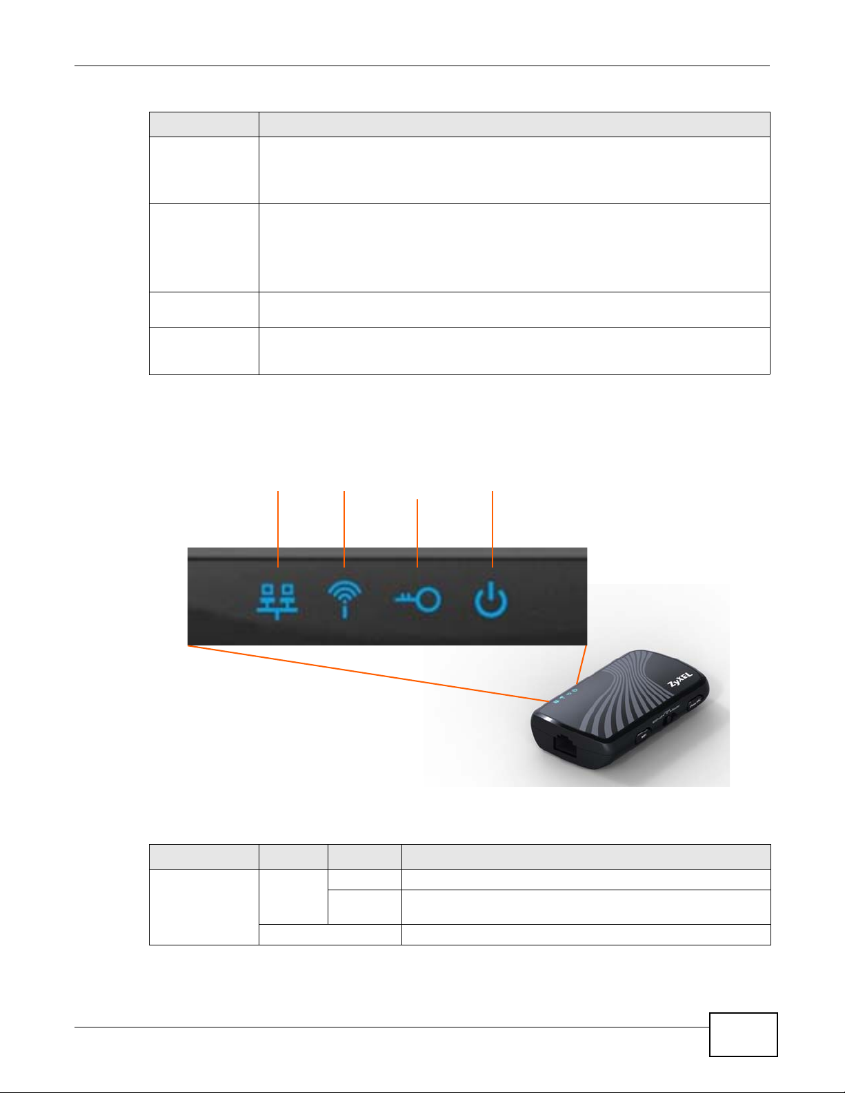
Table 1 General Hardware Features (continued)
PowerWLAN
WPS/
Ethernet
MAC Clone
FEATURE DESCRIPTION
Operation Mode
Switch
Clone MAC Push this for 2 to 5 seconds to clone the first client's MAC address.
Micro USB Connect this to a power supply or computer. Connect to a computer to use as an Ethernet
Reset
(on the underside
of the NBG2105)
1.8.1 LEDs
Figure 2 Top Pan e l LEDs
Chapter 1 Introduction
Slide this to Router to put the NBG2105 into router or AP mode.
Slide this to Client to put the NBG2105 into WLAN client mode.
Slide this to WISP+UR to put the NBG2105 into WISP+UR mode.
Push this for more than 5 seconds to reset the NBG2105’s MAC address to the factory
default.
Note: This only works in Router mode.
interface.
Push this for more than 5 seconds to reset all NBG2105 settings to factory defaults.
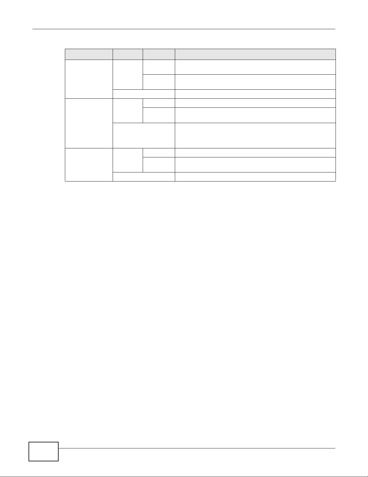
The following table describes the LEDs.
Table 2 Top Panel LEDs
LED COLOR STATUS DESCRIPTION
Ethernet Blue On The NBG2105’s Ethernet connection is ready.
NBG2105 User’s Guide
Blinking The NBG2105 is sending/receiving data through the Ethernet
Off The Ethernet connection is not ready, or has failed.
port.
17
Page 18
Chapter 1 Introduction
Table 2 Top Panel LEDs (continued)
LED COLOR STATUS DESCRIPTION
WLAN Blue On The NBG2105 is ready, but is not sending/receiving data
WPS/MAC Clone Blue On WPS/MAC clone is ready.
Power Blue On The NBG2105 is receiving power and functioning properly.
through the wireless LAN.
Blinking The NBG2105 is sending/receiving data through the wireless
LAN.
Off The wireless LAN is not ready, has failed, or is disabled.
Blinking The NBG2105 is negotiating a WPS connection with a wireless
client or cloning a MAC address.
Off WPS is disabled or has failed.
This LED is off for ten seconds and then the NBG2105
automatically restarts when MAC cloning has failed.
Blinking Boot up process.
The NBG2105 is resetting to factory default settings.
Off The NBG2105 is not receiving power.
18
NBG2105 User’s Guide
Page 19

2.1 Overview
This chapter describes how to access the NBG2105 Web Configurator and provides an overview of
its screens.
The Web Configurator is an HTML-based management interface that allows easy setup and
management of the NBG2105 via Internet browser. Use Internet Explorer 6.0 and later versions,
Mozilla Firefox 3 and later versions, or Safari 2.0 and later versions. The recommended screen
resolution is 1024 by 768 pixels.
In order to use the Web Configurator you need to allow:
• Web browser pop-up windows from your device. Web pop-up blocking is enabled by default in
Windows XP SP (Service Pack) 2.
• JavaScript (enabled by default).
• Java permissions (enabled by default).
CHAPTER 2
Introducing the Web Configurator
Refer to the Troubleshooting chapter (Chapter 17 on page 121) to see how to make sure these
functions are allowed in Internet Explorer.
2.2 Accessing the Web Configurator
The Ethernet port is a WAN port when the NBG2105 is set to Router or AP mode. It is a LAN port
when the NBG2105 is set to WISP+UR or Client mode.
In either mode, users can connect the NBG2105's micro USB port to a computer and install the USB
driver in the computer to access the Web Configurator through a USB-to-Ethernet connection (refer
to the Quick Start Guide).
Table 3 Accessing the NBG2105
OPERATION MODE
Router Mode V V
AP Mode V V
Client Mode V V
WISP + UR Mode V V V
THROUGH THE
ETHERNET LAN PORT
VIA WIRELESS LAN
CONNECTIONS
THROUGH THE
MICRO USB PORT
1 Make sure your NBG2105 hardware is properly connected and prepare your computer or computer
network to connect to the NBG2105 (refer to the Quick Start Guide).
NBG2105 User’s Guide 19
Page 20
Chapter 2 Introdu cing the Web Configurator
2 Launch your web browser.
3 The NBG2105 is in Router mode by default. Type "http://192.168.1.1" as the website address.
If the NBG2105 isn’t in Router mode, the IP address is 192.168.1.2. See Chapter 3 on page 21 for
more information about the modes of the NBG2105.
Your computer must be in the same subnet in order to access this website address.
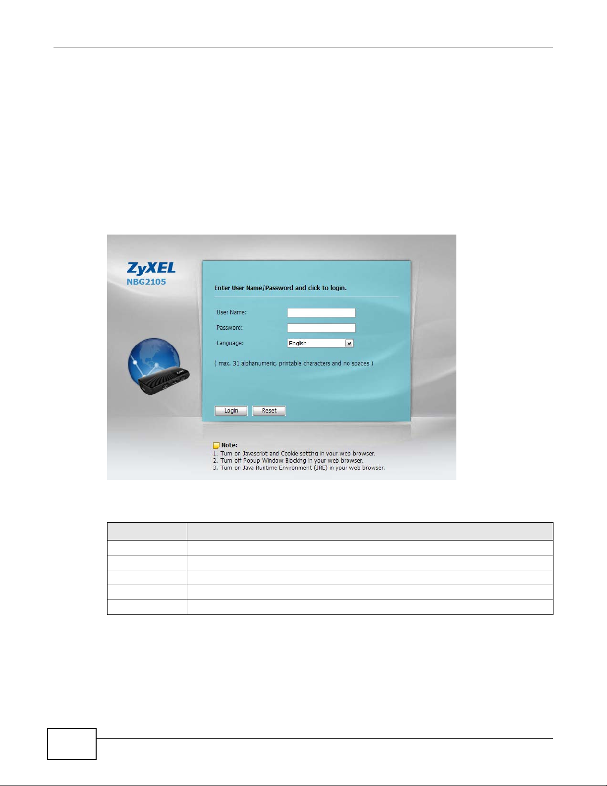
2.2.1 Login Screen
The Web Configurator initially displays the following login screen.
Figure 3 Login screen
20
The following table describes the labels in this screen.
Table 4 Login screen
LABEL DESCRIPTION
User Name Type “admin” (default) as the user name.
Password Type "1234" (default) as the password.
Language Select the language you want to use to configure the Web Configurator. Click Login.
Login Click this to login.
Reset Click this to begin configuring this screen afresh.
NBG2105 User’s Guide
Page 21

3.1 Overview
This chapter introduces the operation modes available on your NBG2105 and how to configure
them. The operation mode is a pre-defined combination of routing, access point (AP) and wireless
client functions to match your network topology and requirements. Use the Operation Mode switch
on the right-side panel (see Section 1.8 on page 16) of the NBG2105 to select the operation mode.
Use the Router Operation Mode screen to configure the selected mode.
3.2 What You Can Do
• Router mode connects the local network to another network, like the Internet. See Section 3.3
on page 21 for details of this mode.
• Access Point mode extends your network by allowing network devices to connect to the
NBG2105 wirelessly. See Section 3.4 on page 24 for details of this mode.
• Client mode enables the NBG2105 to be a wireless client to an upstream AP.
See Section 3.5 on page 27 for details of this mode.
• WISP + UR mode enables the NBG2105 to connect your local network to the Internet through
an ISP’s access point. UR provides Wi-Fi functionality to clients on the LAN side. See Section 3.6
on page 29 for details of this mode.
CHAPTER 3
Operation Modes
Note: Choose your operation mode carefully to avoid having to change it later. If you
select the incorrect operation mode you may not be able to connect to the Internet.
When changing to another mode, the IP address of the NBG2105 changes. The
running applications and services of the network devices connected to the
NBG2105 can be interrupted.
Note: In WISP + UR and Client modes, you should know the SSID and wireless security
details of the access point to which you want to connect.
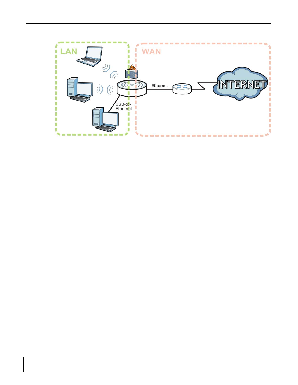
3.3 Router Mode
A router connects your local network with another network, such as the Internet. The router has
two IP addresses, the LAN IP address and the WAN IP address. This mode offers services such as a
firewall, QoS or DDNS.
NBG2105 User’s Guide 21
Page 22
Chapter 3 Operation Modes
Figure 4 Router Mode Application
3.3.1 Setting Router Mode
Select Router mode if your device routes traffic between a local network and another network such
as the Internet. To set Router mode:
1 Make sure the power LED is on (not blinking).
2 Slide the Operation Mode Switch to Router. See Section 1.8 on page 16.
3 The NBG2105 restarts after you slide the Operation Mode Switch.
3.3.2 Navigation Panel
Use the sub-menus on the navigation panel to configure NBG2105 features.
22
NBG2105 User’s Guide
Page 23

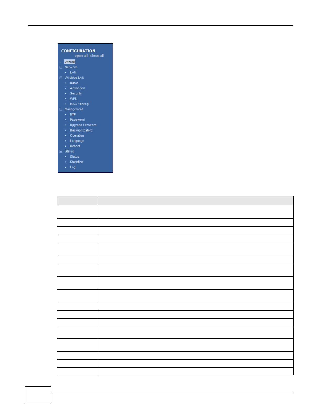
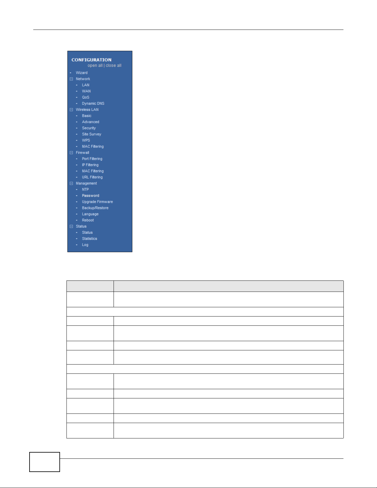
Figure 5 Navigation Panel: Router Mode
Chapter 3 Operatio n Modes
The following table describes the sub-menus.
Table 5 Navigation Panel: Router Mode
MENU FUNCTION
Wizard The Web Configurator’s wizard setup helps you configure your device in router mode for
Network
LAN Use this to configure LAN IP address and subnet mask and DHCP server settings.
WAN Use this allows you to configure ISP parameters, WAN IP address assignment, DNS servers
QoS Use this to reserve bandwidth for certain traffic based on the IP address or MAC address.
Dynamic
DNS
Wireless LAN
Basic Use this to turn the wireless connection on or off and make other basic configuration
Advanced Use this to configure the output power and set the RTS/CTS Threshold.
Security Use this to configure no, WEP, WPA-PSK, WPA2-PSK or WPA2-PSK Mixed wireless
WPS Use this to quickly set up a wireless network with strong security, without having to
the first time.
and the WAN MAC address.
Use this to configure a domain name with a dynamic IP address.
changes.
encryption.
configure security settings manually.
NBG2105 User’s Guide
23
Page 24

Chapter 3 Operation Modes
Table 5 Navigation Panel: Router Mode (continued)
MENU FUNCTION
MAC Filtering Use this to allow or deny wireless stations based on their MAC addresses from connecting
Firewall
Port Filtering Use this to apply filtering based on UDP or TCP port numbers.
IP Filtering Use this to apply filtering based on IP addresses.
MAC Filtering Use this to apply filtering based on MAC addresses.
URL Filtering Use this to apply filtering based on URLs.
Management
NTP Use this to change your NBG2105’s time and date.
Password Use this to change your NBG2105’s system password.
Upgrade
Firmware
Backup/
Restore
Operation Use this to change between access point mode and router mode.
Language Use this to select the language you prefer.
Reboot Use this to restart the NBG2105 without turning the power off.
Status
Status Use this to view system, wireless, local and WAN network information, as well as general
Statistics Use this to show the number of packets sent and received on the Wireless LAN and
Log Use this to look at all of the NBG2105’s logs in one location.
to the NBG2105.
Use this to upload firmware to your NBG2105.
Use this to view information related to factory defaults, backup configuration, and
restoring configuration.
information about the NBG2105.
Ethernet WAN interfaces.
3.4 Access Point Mode
An access point enabled all ethernet ports to be bridged together and be in the same subnet. To
connect to the Internet, another device, such as a router, is required. In Access Point Mode:
• All clients belong to the same subnet.
• All clients of the device are LAN clients. There is no WAN connection.
• The DHCP server is disabled.
• The IP address of the device on the local network is set to 192.168.1.2.
24
NBG2105 User’s Guide
Page 25
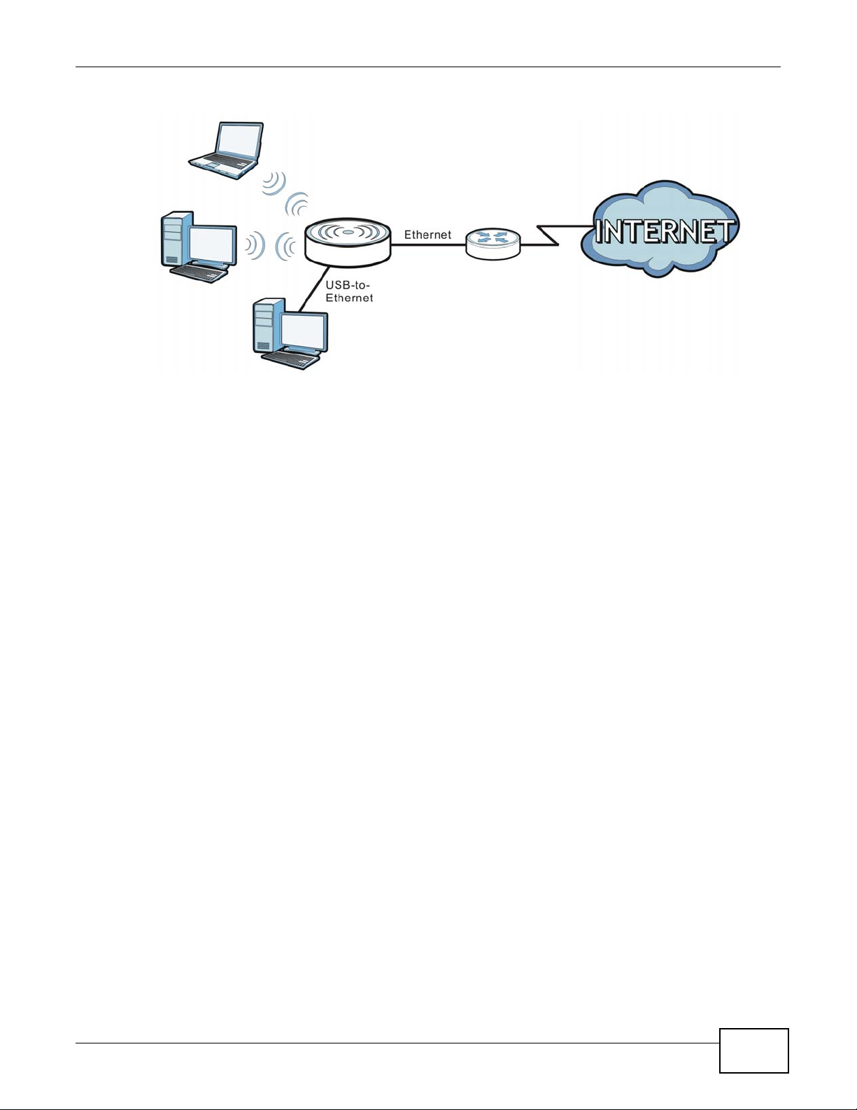
Figure 6 Access Point Mode Application
3.4.1 Setting Access Point Mode
Select Access Point Mode if your device bridges traffic between clients on the same network. To set
Access Point mode:
Chapter 3 Operatio n Modes
1 Make sure the power LED is on (not blinking).
2 Slide the Operation Mode Switch to Router. See Section 1.8 on page 16.
3 The NBG2105 restarts after you slide the Operation Mode Switch.
4 In the Web Configuator, click Management > Operation, select AP and then click Apply
Changes.
3.4.2 Navigation Panel
Use the sub-menus on the navigation panel to configure NBG2105 features.
NBG2105 User’s Guide
25
Page 26
Chapter 3 Operation Modes
Figure 7 Navigation Panel: Access Point Mode
The following table describes the sub-menus.
Table 6 Navigation Panel: Access Point Mode
MENU FUNCTION
Wizard The Web Configurator’s wizard setup helps you configure your device in AP mode for the
first time.
Network
LAN Use this to configure LAN IP address and subnet mask and DHCP server settings.
Wireless LAN
Basic Use this to turn the wireless connection on or off and make other basic configuration
changes.
Advanced Use this to configure the output power and set the RTS/CTS Threshold.
Security Use this to configure no, WEP, WPA-PSK, WPA2-PSK or WPA2-PSK Mixed wireless
WPS Use this to quickly set up a wireless network with strong security, without having to
MAC Filtering Use this to allow or deny wireless stations based on their MAC addresses from connecting
Management
NTP Use this to change your NBG2105’s time and date.
Password Use this to change your NBG2105’s system password.
Upgrade
Firmware
Backup/
Restore
Operation Use this to change between access point mode and router mode.
Language Use this to select the language you prefer.
Reboot Use this to restart the NBG2105 without turning the power off.
encryption.
configure security settings manually.
to the NBG2105.
Use this to upload firmware to your NBG2105.
Use this to view information related to factory defaults, backup configuration, and
restoring configuration.
26
NBG2105 User’s Guide
Page 27
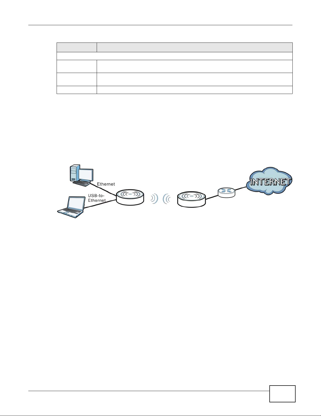
Table 6 Navigation Panel: Access Point Mode (continued)
Access Point
Client
MENU FUNCTION
Status
Status Use this to view system, wireless, local and WAN network information, as well as general
Statistics Use this to show the number of packets sent and received on the Wireless LAN and
Log Use this to look at all of the NBG2105’s logs in one location.
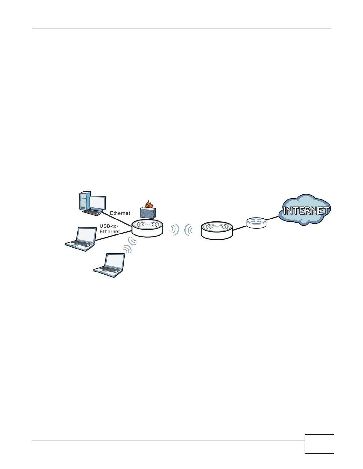
3.5 Client Mode
In Client mode, the NBG2105 acts as a wireless client to connect to an existing access point
wirelessly. It acts just like a wireless client in notebooks/computers. In Client mode:
• The IP address of the device on the local network is set to 192.168.1.2.
Figure 8 Client Mode Application
Chapter 3 Operatio n Modes
information about the NBG2105.
Ethernet WAN interfaces.
3.5.1 Setting Client Mode
Select Client Mode if your device needs a wireless client to connect to an existing access point. To
set Client mode:
1 Make sure the power LED is on (not blinking).
2 Slide the Operation Mode Switch to Client. See Section 1.8 on page 16.
3 The NBG2105 restarts after you slide the Operation Mode Switch.
To allow NBG2105 clients access to the Internet, the NBG2105 must be routed to the access point.
3.5.2 Navigation Panel
Use the sub-menus on the navigation panel to configure NBG2105 features.
NBG2105 User’s Guide
27
Page 28

Chapter 3 Operation Modes
Figure 9 Navigation Panel: Client Mode
The following table describes the sub-menus.
Table 7 Navigation Panel: Client Mode
MENU FUNCTION
Wizard The Web Configurator’s wizard setup helps you configure your device in client mode for the
Network
LAN Use this to configure LAN IP address and subnet mask.
Wireless LAN
Site Survey Use this to scan for and connect to a wireless network automatically.
WPS Use this to quickly set up a wireless network with strong security, without having to
Management
NTP Use this to change your NBG2105’s time and date.
Password Use this to change your NBG2105’s system password.
Upgrade
Firmware
Backup/
Restore
Language Use this to select the language you prefer.
Reboot Use this to restart the NBG2105 without turning the power off.
Status
Status Use this to view system, wireless, local and WAN network information, as well as general
Statistics Use this to show the number of packets sent and received on the Wireless LAN and
Log Use this to look at all of the NBG2105’s logs in one location.
first time.
configure security settings manually.
Use this to upload firmware to your NBG2105.
Use this to view information related to factory defaults, backup configuration, and
restoring configuration.
information about the NBG2105.
Ethernet WAN interfaces.
28
NBG2105 User’s Guide
Page 29
3.6 WISP + UR Mode
A
B
x
y
WISP+UR
Access Point
In WISP (Wireless ISP) + UR (Universal Repeater) mode, your NBG2105 can act as a wireless client
to wirelessly connect to the Internet or an existing network via an access point. In addition, it can
provide Wi-Fi function to the clients on the LAN side. Use this mode if you want to wirelessly
connect to the Internet or have an access point or wireless router in your network. In WISP + UR
mode, the IP address of the device on the local network is 192.168.1.2.
Note: Make sure your network and the remote network are NOT in the same subnet. If
the access point or wireless router is using 192.168.1.x, the NBG2105 in WISP +
UR mode needs to use something else, say 192.168.2.x.
Note: When the NBG2105 is in WISP + UR mode, you still need to enter your ISP
information in the WAN screen in order to access the Internet.
In the example below, one NBG2105 is configured as WISP +UR mode (A) and another is used as
an access point (B). The NBG2105 (A) wirelessly connects to the available access point (B), and
can allow the clients (x and y) to access the network through it using a wireless connection.
Figure 10 WISP + UR Mode Application
Chapter 3 Operatio n Modes
3.6.1 Setting WISP + UR Mode
Select WISP + UR Mode if your NBG2105 needs a wireless client to connect to an existing access
point, still have router functions, and also allow wireless clients to associate with the NBG2105. To
set WISP + UR mode:
1 Make sure the power LED is on (not blinking).
2 Slide the Operation Mode Switch to WISP + UR. See Section 1.8 on page 16.
3 The NBG2105 restarts after you slide the Operation Mode Switch.
3.6.2 Navigation Panel
Use the sub-menus on the navigation panel to configure NBG2105 features.
NBG2105 User’s Guide
29
Page 30
Chapter 3 Operation Modes
Figure 11 Navigation Panel: WISP+UR Mode
The following table describes the sub-menus.
Table 8 Navigation Panel: WISP+UR Mode
MENU FUNCTION
Wizard The Web Configurator’s wizard setup helps you configure your device in WISP+UR mode
for the first time.
Network
LAN Use this to configure LAN IP address and subnet mask.
WAN Use this allows you to configure ISP parameters, WAN IP address assignment, DNS servers
QoS Use this to reserve bandwidth for certain traffic based on the IP address or MAC address.
Dynamic
DNS
Wireless LAN
Basic Use this to turn the wireless connection on or off and make other basic configuration
Advanced Use this to configure the output power and set the RTS/CTS Threshold.
Security Use this to configure no, WEP, WPA-PSK, WPA2-PSK or WPA2-PSK Mixed wireless
Site Survey Use this to scan for and connect to a wireless network automatically.
WPS Use this to quickly set up a wireless network with strong security, without having to
and the WAN MAC address.
Use this to configure a domain name with a dynamic IP address.
changes.
encryption.
configure security settings manually.
30
NBG2105 User’s Guide
Page 31

Chapter 3 Operatio n Modes
Table 8 Navigation Panel: WISP+UR Mode (continued)
MENU FUNCTION
MAC Filtering Use this to allow or deny wireless stations based on their MAC addresses from connecting
to the NBG2105.
Firewall
Port Filtering Use this to apply filtering based on UDP or TCP port numbers.
IP Filtering Use this to apply filtering based on IP addresses.
MAC Filtering Use this to apply filtering based on MAC addresses.
URL Filtering Use this to apply filtering based on URLs.
Management
NTP Use this to change your NBG2105’s time and date.
Password Use this to change your NBG2105’s system password.
Upgrade
Firmware
Backup/
Restore
Language Use this to select the language you prefer.
Reboot Use this to restart the NBG2105 without turning the power off.
Status
Status Use this to view system, wireless, local and WAN network information, as well as general
Statistics Use this to show the number of packets sent and received on the Wireless LAN and
System Log Use this to look at all of the NBG2105’s logs in one location.
Use this to upload firmware to your NBG2105.
Use this to view information related to factory defaults, backup configuration, and
restoring configuration.
information about the NBG2105.
Ethernet WAN interfaces.
NBG2105 User’s Guide
31
Page 32

Chapter 3 Operation Modes
32
NBG2105 User’s Guide
Page 33

4.1 Overview
This chapter provides information on the wizard setup screens in the Web Configurator.
The Web Configurator’s wizard setup helps you configure your device in router mode for the first
time.
4.2 Welcome Screen
Launch your web browser and type "http://192.168.1.1" as the website address. Type "admin"
(default) as the user name and "1234" (default) as the password. Click Login.
CHAPTER 4
Router Setup Wizard
Click Wizard in router mode to open the Welcome screen. Click Next after reading the instructions
on this screen.
Figure 12 Welcome
4.3 WAN Interface Setup
The NBG2105 offers three WAN access types. They are Static IP, DHCP Client or PPPoE.
The following screen depends on your WAN access type. Enter the details provided by your Internet
Service Provider (ISP) in the fields (if any).
NBG2105 User’s Guide 33
Page 34

Chapter 4 Router Setup Wizard
4.3.1 WAN Access Type: Static IP
Select Static IP as the WAN Access Type to setup a static IP Configuration on the WAN port.
Complete the fields described. Click Next to proceed with the Wireless Network Name (SSID)
screen.
Figure 13 WAN Access Type: Static IP
The following table describes the labels in this screen.
Table 9 WAN Access Type: Static IP
LABEL DESCRIPTION
WAN Access Type Select Static IP to enable manual configuration of all NBG2105 IP settings.
Internet IP Address Enter the Internet-facing IP address.
Subnet Mask Enter the subnet mask of the NBG2105 WAN interface.
Default Gateway Enter the IP address of a default gateway to the Internet.
DNS Enter the IP address of the DNS server.
Cancel Click this to cancel the wizard.
Back Click this to go back to the previous step in the wizard.
Next Click this to go to the next step in the wizard.
4.3.2 WAN Access Type: DHCP Client
Select DHCP Client as the WAN Access Type to make the WAN port setup its IP configuration via
DHCP. Click Next to proceed with the Wireless Network Name (SSID) screen.
Figure 14 WAN Access Type: DHCP Client
34
NBG2105 User’s Guide
Page 35

The following table describes the labels in this screen.
Table 10 WAN Access Type: DHCP Client
LABEL DESCRIPTION
WAN Access Type Select DHCP Client to make the NBG2105 get its IP configuration from a DHCP server.
Cancel Click this to cancel the wizard.
Back Click this to go back to the previous step in the wizard.
Next Click this to go to the next step in the wizard.
4.3.3 WAN Access Type: PPPoE
Point-to-Point Protocol over Ethernet (PPPoE) functions as a dial-up connection. PPPoE is an IETF
(Internet Engineering Task Force) standard specifying how a host personal computer interacts with
a broadband modem (for example DSL, cable, wireless, etc.) to achieve access to high-speed data
networks.
For the service provider, PPPoE offers an access and authentication method that works with existing
access control systems (for instance, RADIUS).
One of the benefits of PPPoE is the ability to let end users access one of multiple network services,
a function known as dynamic service selection. This enables the service provider to easily create
and offer new IP services for specific users.
Chapter 4 Router Setup Wizard
Operationally, PPPoE saves significant effort for both the subscriber and the ISP/carrier, as it
requires no specific configuration of the broadband modem at the subscriber's site.
By implementing PPPoE directly on the NBG2105 (rather than individual computers), the computers
on the LAN do not need PPPoE software installed, since the NBG2105 does that part of the task.
Furthermore, with NAT, all of the LAN's computers will have Internet access.
Select PPPoE as the WAN Access Type to make the WAN port setup its IP configuration via
PPPoE. Complete the fields described. Click Next to proceed with the Wireless Network Name
(SSID) screen.
Figure 15 WAN Access Type: PPPoE
NBG2105 User’s Guide
35
Page 36

Chapter 4 Router Setup Wizard
The following table describes the labels in this screen.
Table 11 WAN Access Type: PPPoE
LABEL DESCRIPTION
WAN Access Type Select PPPoE to make the NBG2105 get its IP configuration via PPPoE.
User Name Enter the user name provided by your ISP.
Password Enter the password provided by your ISP.
Cancel Click this to cancel the wizard.
Back Click this to go back to the previous step in the wizard.
Next Click this to go to the next step in the wizard.
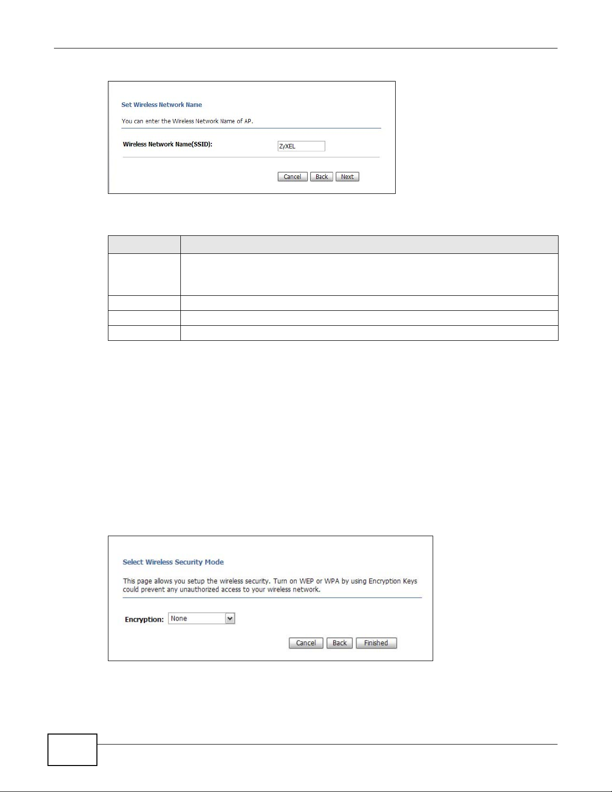
4.4 Wireless Network Name (SSID) Setup
Name your wireless network by entering an SSID. Click Next to proceed with the Wireless
Security Mode screen.
Figure 16 Wireless Network Name (SSID)
The following table describes the labels in this screen.
Table 12 Wireless Network Name (SSID)
LABEL DESCRIPTION
Wireless
Network Name
(SSID)
Cancel Click this to cancel the wizard.
Back Click this to go back to the previous step in the wizard.
Next Click this to go to the next step in the wizard.
Enter a descriptive name (up to 32 printable 7-bit ASCII characters) for the wireless LAN.
If you change this field on the NBG2105, make sure all wireless stations use the same SSID
in order to access the network.
4.5 Wireless Security
Configure the wireless security settings on your NBG2105 in the following screen. The fields that
show up depend on the kind of security you select.
36
NBG2105 User’s Guide
Page 37

4.5.1 Encryption: None
Choose None in the Encryption field to let wireless devices within range access your wireless
network. Complete the fields described. Click Finished to save the configuration end exit the
wizard.
Figure 17 Encryption: None
The following table describes the labels in this screen.
Table 13 Encryption: None
LABEL DESCRIPTION
Encryption Select None to have no wireless LAN security configured. If you do not enable any wireless
security on your NBG2105, your network is accessible to any wireless networking device
that is within range.
Cancel Click this to cancel the wizard.
Back Click this to go back to the previous step in the wizard.
Finished Click this to finish the wizard.
Chapter 4 Router Setup Wizard
4.5.2 Encryption: WEP
Choose WEP in the Encryption field to protect your wireless network with Wired Equivalent
Privacy. Complete the fields described. Click Finished to save the configuration end exit the wizard.
Figure 18 Encryption: WEP
NBG2105 User’s Guide
37
Page 38

Chapter 4 Router Setup Wizard
The following table describes the labels in this screen.
Table 14 Encryption: WEP
LABEL DESCRIPTION
Encryption Select WEP to allow clients to associate this network with WEP authentication.
Key Length Select 64-bit or 128-bit.
Key Format Select Hex to enter hexadecimal characters as a WEP key.
Key Setting The WEP keys are used to encrypt data. Both the NBG2105 and the wireless stations must
Cancel Click this to cancel the wizard.
Back Click this to go back to the previous step in the wizard.
Finished Click this to finish the wizard.
This dictates the length of the security key that the network is going to use.
Select ASCII to enter ASCII characters as WEP key.
use the same WEP key for data transmission.
If you chose 64-bit in the Key Format field, then enter any 5 ASCII characters or 10
hexadecimal characters ("0-9", "A-F").
If you chose 128-bit in the Key Format field, then enter 13 ASCII characters or 26
hexadecimal characters ("0-9", "A-F").
4.5.3 Encryption: WPA-PSK, WPA2-PSK or WPA2-PSK Mixed
Choose WPS-PSK, WPA2-PSK or WPA2-PSK Mixed in the Encryption field to protect your
wireless network with WPA-PSK, WPA2-PSK or both at the same time. Complete the fields
described. Click Finished to save the configuration end exit the wizard.
Figure 19 Encryption: WPA2-PSK Mixed
Note: Although only the WPA2-PSK Mixed screen is shown, all fields are the same for
WPA-PSK, WPA2-PSK or WPA2-PSK Mixed screens.
38
NBG2105 User’s Guide
Page 39

Chapter 4 Router Setup Wizard
The following table describes the labels in this screen.
Table 15 Encryption: WPA-PSK, WPA2-PSK or WPA2-PSK Mixed
LABEL DESCRIPTION
Encryption Select WPA-PSK, WPA2-PSK or WPA2-PSK Mixed to allow clients to associate this
Pre-Shared Key
Format
Pre-Shared Key If Passphrase was selected in the Pre-Shared Key Format field, type a pre-shared
Cancel Click this to cancel the wizard.
Back Click this to go back to the previous step in the wizard.
Finished Click this to finish the wizard.
network with WPA-PSK, WPA2-PSK or either WPA-PSK or WPA2-PSK authentication.
Select Passphrase to make the NBG2105 generate a key from a phrase typed into the
Pre-Shared Key field.
Select Hex to configure the NBG2105 to accept a key in hexadecimal format in the
Pre-Shared Key field.
key from 8 to 63 case-sensitive keyboard characters.
If Hex was selected in the Pre-Shared Key Format field, type a pre-shared key using
hexadecimal characters ("0-9", "A-F").
NBG2105 User’s Guide
39
Page 40

Chapter 4 Router Setup Wizard
40
NBG2105 User’s Guide
Page 41

5.1 Overview
This chapter provides information on the wizard setup screens in the Web Configurator.
The Web Configurator’s wizard setup helps you configure your device in AP mode for the first time.
5.2 Welcome Screen
Launch your web browser and type "http://192.168.1.2" as the website address. Type "admin"
(default) as the user name and "1234" (default) as the password. Click Login.
Click Wizard in router mode to open the Welcome screen. Click Next after reading the instructions
on this screen.
CHAPTER 5
AP Setup Wizard
Figure 20 Welcome
5.3 Wireless Network Name (SSID) Setup
Name your wireless network by entering an SSID. Click Next to proceed with the Wireless
Security Mode screen.
NBG2105 User’s Guide 41
Page 42
Chapter 5 AP Setup Wizard
Figure 21 Wireless Network Name (SSID)
The following table describes the labels in this screen.
Table 16 Wireless Network Name (SSID)
LABEL DESCRIPTION
Wireless
Network Name
(SSID)
Cancel Click this to cancel the wizard.
Back Click this to go back to the previous step in the wizard.
Next Click this to go to the next step in the wizard.
Enter a descriptive name (up to 32 printable 7-bit ASCII characters) for the wireless LAN.
If you change this field on the NBG2105, make sure all wireless stations use the same SSID
in order to access the network.
5.4 Wireless Security
Configure the wireless security settings on your NBG2105 in the following screen. The fields that
show up depend on the kind of security you select.
5.4.1 Encryption: None
Choose None in the Encryption field to let wireless devices within range access your wireless
network. Complete the fields described. Click Finished to save the configuration end exit the
wizard.
Figure 22 Encryption: None
42
NBG2105 User’s Guide
Page 43

The following table describes the labels in this screen.
Table 17 Encryption: None
LABEL DESCRIPTION
Encryption Select None to have no wireless LAN security configured. If you do not enable any wireless
security on your NBG2105, your network is accessible to any wireless networking device
that is within range.
Cancel Click this to cancel the wizard.
Back Click this to go back to the previous step in the wizard.
Finished Click this to finish the wizard.
5.4.2 Encryption: WEP
Choose WEP in the Encryption field to protect your wireless network with Wired Equivalent
Privacy. Complete the fields described. Click Finished to save the configuration end exit the wizard.
Figure 23 Encryption: WEP
Chapter 5 AP Setup Wizard
The following table describes the labels in this screen.
Table 18 Encryption: WEP
LABEL DESCRIPTION
Encryption Select WEP to allow clients to associate this network with WEP authentication.
Key Length Select 64-bit or 128-bit.
Key Format Select Hex to enter hexadecimal characters as a WEP key.
Key Setting The WEP keys are used to encrypt data. Both the NBG2105 and the wireless stations must
Cancel Click this to cancel the wizard.
Back Click this to go back to the previous step in the wizard.
Finished Click this to finish the wizard.
NBG2105 User’s Guide
This dictates the length of the security key that the network is going to use.
Select ASCII to enter ASCII characters as WEP key.
use the same WEP key for data transmission.
If you chose 64-bit in the Key Format field, then enter any 5 ASCII characters or 10
hexadecimal characters ("0-9", "A-F").
If you chose 128-bit in the Key Format field, then enter 13 ASCII characters or 26
hexadecimal characters ("0-9", "A-F").
43
Page 44

Chapter 5 AP Setup Wizard
5.4.3 Encryption: WPA-PSK, WPA2-PSK or WPA2-PSK Mixed
Choose WPS-PSK, WPA2-PSK or WPA2-PSK Mixed in the Encryption field to protect your
wireless network with WPA-PSK, WPA2-PSK or both at the same time. Complete the fields
described. Click Finished to save the configuration end exit the wizard.
Figure 24 Encryption: WPA2-PSK Mixed
Note: Although only the WPA2-PSK Mixed screen is shown, all fields are the same for
WPA-PSK, WPA2-PSK or WPA2-PSK Mixed screens.
The following table describes the labels in this screen.
Table 19 Encryption: WPA-PSK, WPA2-PSK or WPA2-PSK Mixed
LABEL DESCRIPTION
Encryption Select WPA-PSK, WPA2-PSK or WPA2-PSK Mixed to allow clients to associate this
network with WPA-PSK, WPA2-PSK or either WPA-PSK or WPA2-PSK authentication.
Pre-Shared Key
Format
Pre-Shared Key If Passphrase was selected in the Pre-Shared Key Format field, type a pre-shared
Cancel Click this to cancel the wizard.
Back Click this to go back to the previous step in the wizard.
Finished Click this to finish the wizard.
Select Passphrase to make the NBG2105 generate a key from a phrase typed into the
Pre-Shared Key field.
Select Hex to configure the NBG2105 to accept a key in hexadecimal format in the
Pre-Shared Key field.
key from 8 to 63 case-sensitive keyboard characters.
If Hex was selected in the Pre-Shared Key Format field, type a pre-shared key using
hexadecimal characters ("0-9", "A-F").
44
NBG2105 User’s Guide
Page 45

6.1 Overview
This chapter provides information on the wizard setup screens in the Web Configurator.
The Web Configurator’s wizard setup helps you configure your device in Client mode for the first
time.
6.2 Welcome Screen
Launch your web browser and type "http://192.168.1.2" as the website address. Type "admin"
(default) as the user name and "1234" (default) as the password. Click Login.
CHAPTER 6
Client Setup Wizard
Click Wizard in client mode to open the Welcome screen. Click Next after reading the instructions
on this screen.
Figure 25 Welcome
6.3 Wireless Network Name Setup
Name your wireless network by entering an SSID or by clicking Site Survey and selecting one of
the detected devices. Click Next to proceed with the Wireless Security Mode screen.
NBG2105 User’s Guide 45
Page 46

Chapter 6 Client Setup Wizard
Figure 26 Wireless Network Name Setup
The following table describes the labels in this screen.
Table 20 Wireless Network Name Setup
LABEL DESCRIPTION
Wireless Network
Name (SSID)
Channel Enter the channel number used by the wireless device to which the NBG2105 is
Site Survey Click this to search for available wireless devices within transmission range and update
SSID This shows the SSID of the wireless device.
BSSID This shows the MAC address of the wireless device.
Channel This shows the channel number and wireless standard used by this wireless device.
Type This shows the type of device found in the survey.
Encrypt This displays the data encryption and authentication method used by this wireless
Signal This displays the strength of the wireless signal. The signal strength mainly depends on
Select Click this to select a device.
Cancel Click this to cancel the wizard.
Enter the SSID of the AP to which you want the NBG2105 in client mode to connect.
connecting. This is optional if the AP does not broadcast and hides the SSID.
this table.
device.
the antenna output power and the distance between your NBG2105 and this device.
46
NBG2105 User’s Guide
Page 47

Table 20 Wireless Network Name Setup (continued)
LABEL DESCRIPTION
Back Click this to go back to the previous step in the wizard.
Next Click this to open a screen to configure wireless security options.
6.4 Wireless Security
Configure the wireless security settings on your NBG2105 in the following screen. The fields that
show up depend on the kind of security you select.
6.4.1 Encryption: None
Choose None in the Encryption field to let wireless devices within range access your wireless
network. Complete the fields described. Click Finished to save the configuration end exit the
wizard.
Figure 27 Encryption: None
Chapter 6 Client Setup Wizard
The following table describes the labels in this screen.
Table 21 Encryption: None
LABEL DESCRIPTION
Encryption Select None to have no wireless LAN security configured. If you do not enable any wireless
security on your NBG2105, your network is accessible to any wireless networking device
that is within range.
Cancel Click this to cancel the wizard.
Back Click this to go back to the previous step in the wizard.
Finished Click this to finish the wizard.
6.4.2 Encryption: WEP
Choose WEP in the Encryption field to protect your wireless network with Wired Equivalent
Privacy. Complete the fields described. Click Finished to save the configuration end exit the wizard.
NBG2105 User’s Guide
47
Page 48

Chapter 6 Client Setup Wizard
Figure 28 Encryption: WEP
The following table describes the labels in this screen.
Table 22 Encryption: WEP
LABEL DESCRIPTION
Encryption Select WEP to allow clients to associate this network with WEP authentication.
Key Length Select 64-bit or 128-bit.
Key Format Select Hex to enter hexadecimal characters as a WEP key.
This dictates the length of the security key that the network is going to use.
Select ASCII to enter ASCII characters as WEP key.
Key Setting The WEP keys are used to encrypt data. Both the NBG2105 and the wireless stations must
Cancel Click this to cancel the wizard.
Back Click this to go back to the previous step in the wizard.
Finished Click this to finish the wizard.
use the same WEP key for data transmission.
If you chose 64-bit in the Key Format field, then enter any 5 ASCII characters or 10
hexadecimal characters ("0-9", "A-F").
If you chose 128-bit in the Key Format field, then enter 13 ASCII characters or 26
hexadecimal characters ("0-9", "A-F").
6.4.3 Encryption: WPA-PSK or WPA2-PSK
Choose WPA-PSK or WPA2-PSK in the Encryption field to protect your wireless network with
WPA-PSK or WPA2-PSK encryption. Complete the fields described. Click Finished to save the
configuration end exit the wizard.
48
NBG2105 User’s Guide
Page 49

Chapter 6 Client Setup Wizard
Figure 29 Encryption: WPA2-PSK
Note: Although only the WPA2-PSK screen is shown, all fields are the same for the
WPA-PSK screen.
The following table describes the labels in this screen.
Table 23 Encryption: WPA-PSK or WPA2-PSK
LABEL DESCRIPTION
Encryption Select WPA-PSK or WPA2-PSK to allow clients to associate this network with WPA or
WPA2 authentication.
Pre-Shared Key
Format
Select Passphrase to make the NBG2105 generate a key from a phrase typed into the
Pre-Shared Key field.
Select HEX to configure the NBG2105 to accept a key in hexadecimal format in the
Pre-Shared Key field.
Pre-Shared Key If Passphrase was selected in the Pre-Shared Key Format field, type a pre-shared
key from 8 to 63 case-sensitive keyboard characters.
If HEX was selected in the Pre-Shared Key Format field, type a pre-shared key using
hexadecimal characters ("0-9", "A-F").
Cancel Click this to cancel the wizard.
Back Click this to go back to the previous step in the wizard.
Finished Click this to finish the wizard.
NBG2105 User’s Guide
49
Page 50

Chapter 6 Client Setup Wizard
50
NBG2105 User’s Guide
Page 51

7.1 Overview
This chapter provides information on the wizard setup screens in the Web Configurator.
The Web Configurator’s wizard setup helps you configure the wireless network name and wireless
network security in WISP+UR mode for the first time.
7.2 Welcome Screen
Launch your web browser and type "http://192.168.1.2" as the website address. Type "admin"
(default) as the user name and "1234" (default) as the password. Click Login.
CHAPTER 7
WISP+UR Setup Wizard
Click Wizard in WISP+UR mode to open the Welcome screen. Click Next after reading the
instructions on this screen.
Figure 30 Welcome
7.3 WAN Interface Setup
Click Network > WAN to change how your NBG2105’s WAN interface accesses your ISP. The
screen differs according to the WAN Access Type you choose.
7.3.1 Static IP
Select Static IP from WAN Access Type to configure all NBG2105 WAN IP configuration settings
manually.
NBG2105 User’s Guide 51
Page 52

Chapter 7 WISP+UR Setup Wizard
Figure 31 WAN: Static IP
The following table describes the labels in this screen.
Table 24 WAN: Static IP
LABEL DESCRIPTION
WAN Access Type Select Static IP to enable manual configuration of all NBG2105 IP settings.
Internet IP Address Enter the Internet-facing IP address.
Subnet Mask Enter the subnet mask of the NBG2105 WAN interface.
Default Gateway Enter the IP address of a default gateway to the Internet.
DNS Enter the IP address of the DNS server.
Cancel Click this to cancel the wizard.
Back Click this to go back to the previous step in the wizard.
Next Click this to open a screen to configure wireless security options.
7.3.2 DHCP Client
Select DHCP Client from WAN Access Type to make the NBG2105 get its IP configuration from a
DHCP server.
Figure 32 WAN: DHCP Client
The following table describes the labels in this screen.
Table 25 WAN: DHCP Client
LABEL DESCRIPTION
WAN Access Type Select DHCP Client to make the NBG2105 get its IP configuration from a DHCP server.
Cancel Click this to cancel the wizard.
52
NBG2105 User’s Guide
Page 53

Table 25 WAN: DHCP Client (continued)
LABEL DESCRIPTION
Back Click this to go back to the previous step in the wizard.
Next Click this to open a screen to configure wireless security options.
7.3.3 PPPoE
The NBG2105 supports PPPoE (Point-to-Point Protocol over Ethernet). PPPoE is an IETF standard
(RFC 2516) specifying how a personal computer (PC) interacts with a broadband modem (DSL,
cable, wireless, etc.) connection. The PPPoE option is for a dial-up connection using PPPoE.
For the service provider, PPPoE offers an access and authentication method that works with existing
access control systems (for example Radius).
One of the benefits of PPPoE is the ability to let you access one of multiple network services, a
function known as dynamic service selection. This enables the service provider to easily create and
offer new IP services for individuals.
Operationally, PPPoE saves significant effort for both you and the ISP or carrier, as it requires no
specific configuration of the broadband modem at the customer site.
Chapter 7 WISP+UR Setup Wizard
By implementing PPPoE directly on the NBG2105 (rather than individual computers), the computers
on the LAN do not need PPPoE software installed, since the NBG2105 does that part of the task.
Furthermore, with NAT, all of the LANs’ computers will have access.
Select PPPoE from WAN Access Type to make the NBG2105 get its IP configuration via PPPoE.
Figure 33 WAN: PPPoE
The following table describes the labels in this screen.
Table 26 WAN: PPPoE
LABEL DESCRIPTION
WAN Access Type Select PPPoE to make the NBG2105 get its IP configuration via PPPoE.
User Name Enter the user name provided by your ISP.
Password Enter the password provided by your ISP.
Cancel Click this to cancel the wizard.
Back Click this to go back to the previous step in the wizard.
Next Click this to open a screen to configure wireless security options.
NBG2105 User’s Guide
53
Page 54

Chapter 7 WISP+UR Setup Wizard
7.4 Wireless Network Name Setup
Name your wireless network by entering an SSID or by clicking Site Survey and selecting one of
the detected devices. Click Next to proceed with the Wireless Security Mode screen.
Figure 34 Wireless Network Name Setup
54
The following table describes the labels in this screen.
Table 27 Wireless Network Name Setup
LABEL DESCRIPTION
Wireless Network
Name (SSID)
Channel Enter the channel number used by the wireless device to which the NBG2105 is
Site Survey Click this to search for available wireless devices within transmission range and update
SSID This shows the SSID of the wireless device.
BSSID This shows the MAC address of the wireless device.
Channel This shows the channel number and wireless standard used by this wireless device.
Type This shows the type of device found in the survey.
Enter the SSID of the AP to which you want the NBG2105 in WISP+UR mode to
connect.
connecting. This is optional if the AP does not broadcast and hides the SSID.
this table.
NBG2105 User’s Guide
Page 55

Table 27 Wireless Network Name Setup (continued)
LABEL DESCRIPTION
Encrypt This displays the data encryption and authentication method used by this wireless
device.
Signal This displays the strength of the wireless signal. The signal strength mainly depends on
the antenna output power and the distance between your NBG2105 and this device.
Select Click this to select a device.
Cancel Click this to cancel the wizard.
Back Click this to go back to the previous step in the wizard.
Next Click this to open a screen to configure wireless security options.
7.5 Wireless Security
Configure the wireless security settings on your NBG2105 in the following screen. The fields that
show up depend on the kind of security you select.
7.5.1 Encryption: None
Chapter 7 WISP+UR Setup Wizard
Choose None in the Encryption field to let wireless devices within range access your wireless
network. Complete the fields described. Click Finished to save the configuration end exit the
wizard.
Figure 35 Encryption: None
The following table describes the labels in this screen.
Table 28 Encryption: None
LABEL DESCRIPTION
Encryption Select None to have no wireless LAN security configured. If you do not enable any wireless
security on your NBG2105, your network is accessible to any wireless networking device
that is within range.
Cancel Click this to cancel the wizard.
Back Click this to go back to the previous step in the wizard.
Finished Click this to finish the wizard.
NBG2105 User’s Guide
55
Page 56

Chapter 7 WISP+UR Setup Wizard
7.5.2 Encryption: WEP
Choose WEP in the Encryption field to protect your wireless network with Wired Equivalent
Privacy. Complete the fields described. Click Finished to save the configuration end exit the wizard.
Figure 36 Encryption: WEP
The following table describes the labels in this screen.
Table 29 Encryption: WEP
LABEL DESCRIPTION
Encryption Select WEP to allow clients to associate this network with WEP authentication.
Key Length Select 64-bit or 128-bit.
This dictates the length of the security key that the network is going to use.
Key Format Select Hex to enter hexadecimal characters as a WEP key.
Select ASCII to enter ASCII characters as WEP key.
Key Setting The WEP keys are used to encrypt data. Both the NBG2105 and the wireless stations must
use the same WEP key for data transmission.
If you chose 64-bit in the Key Format field, then enter any 5 ASCII characters or 10
hexadecimal characters ("0-9", "A-F").
If you chose 128-bit in the Key Format field, then enter 13 ASCII characters or 26
hexadecimal characters ("0-9", "A-F").
Cancel Click this to cancel the wizard.
Back Click this to go back to the previous step in the wizard.
Finished Click this to finish the wizard.
7.5.3 Encryption: WPA-PSK or WPA2-PSK
Choose WPA-PSK or WPA2-PSK in the Encryption field to protect your wireless network with
WPA-PSK or WPA2-PSK encryption. Complete the fields described. Click Finished to save the
configuration end exit the wizard.
56
NBG2105 User’s Guide
Page 57

Chapter 7 WISP+UR Setup Wizard
Figure 37 Encryption: WPA2-PSK
Note: Although only the WPA2-PSK screen is shown, all fields are the same for the
WPA-PSK screen.
The following table describes the labels in this screen.
Table 30 Encryption: WPA-PSK or WPA2-PSK
LABEL DESCRIPTION
Encryption Select WPA-PSK or WPA2-PSK to allow clients to associate this network with WPA or
WPA2 authentication.
Pre-Shared Key
Format
Select Passphrase to make the NBG2105 generate a key from a phrase typed into the
Pre-Shared Key field.
Select HEX to configure the NBG2105 to accept a key in hexadecimal format in the
Pre-Shared Key field.
Pre-Shared Key If Passphrase was selected in the Pre-Shared Key Format field, type a pre-shared
key from 8 to 63 case-sensitive keyboard characters.
If HEX was selected in the Pre-Shared Key Format field, type a pre-shared key using
hexadecimal characters ("0-9", "A-F").
Cancel Click this to cancel the wizard.
Back Click this to go back to the previous step in the wizard.
Finished Click this to finish the wizard.
NBG2105 User’s Guide
57
Page 58

Chapter 7 WISP+UR Setup Wizard
58
NBG2105 User’s Guide
Page 59

CHAPTER 8
8.1 Overview
This chapter provides tutorials for setting up your NBG2105.
• Set Up a Wireless Network with WPS
• Configure Wireless Security without WPS
8.2 Set Up a Wireless Network with WPS
This section gives you an example of how to set up wireless network using WPS. This example uses
the NBG2105 as the AP and NWD210N as the wireless client which connects to a notebook.
Tutorials
Note: The wireless client must be a WPS-aware device (for example, a WPS USB adapter
or PCI card).
There are two WPS methods for creating a secure connection. This tutorial shows you how to do
both.
• Push Button Configuration (PBC) - create a secure wireless network simply by pressing a
button. See Section 8.2.1 on page 59.This is the easier method.
• PIN Configuration - create a secure wireless network simply by entering a wireless client's PIN
(Personal Identification Number) in the NBG2105’s interface. See Section 8.2.2 on page 60. This
is the more secure method, since one device can authenticate the other.
8.2.1 Push Button Configuration (PBC)
1 Make sure that your NBG2105 is turned on and working as an AP or wireless router. Make sure that
the device is placed within range of your notebook.
2 Make sure that you have installed the wireless client (this example uses the NWD210N) driver and
utility in your notebook.
3 In the wireless client utility, find the WPS settings. Enable WPS and press the WPS button (Start or
WPS button)
4 Log into NBG2105’s Web Configurator and press the Start PBC button in the Wireless LAN >
WPS screen.
NBG2105 User’s Guide 59
Page 60

Chapter 8 Tutorials
Wireless Client
Access Point
SECURITY INFO
COMMUNICATION
WITHIN 2 MINUTES
Note: Your NBG2105 has a WPS button located on its panel, as well as a WPS button in its
Note: It doesn’t matter which button is pressed first. You must press the second button
The NBG2105 sends the proper configuration settings to the wireless client. This may take up to
two minutes. Then the wireless client is able to communicate with the NBG2105 securely.
The following figure shows you an example to set up wireless network and security by pressing a
button on both NBG2105 and wireless client (the NWD210N in this example).
Figure 38 Example WPS Process: PBC Method
configuration utility. Both buttons have exactly the same function; you can use one
or the other.
within two minutes of pressing the first one.
8.2.2 PIN Configuration
When you use the PIN configuration method, you need to use both NBG2105’s configuration
interface and the client’s utilities.
1 Launch your wireless client’s configuration utility. Go to the WPS settings and select the PIN method
to get a PIN number.
2 Enter the PIN number into the Station PIN Number field in the Wireless LAN > WPS screen on
the NBG2105.
60
NBG2105 User’s Guide
Page 61

Chapter 8 Tutorials
WITHIN 2 MINUTES
Wireless Client
Access Point
3 Click Start buttons (or button next to the PIN field) on both the wireless client utility screen and the
NBG2105’s Wireless LAN > WPS screen within two minutes.
The NBG2105 authenticates the wireless client and sends the proper configuration settings to the
wireless client. This may take up to two minutes. Then the wireless client is able to communicate
with the NBG2105 securely.
The following figure shows you the example to set up wireless network and security on NBG2105
and wireless client (ex. NWD210N in this example) by using PIN method.
Figure 39 Example WPS Process: PIN Method
8.3 Configure Wireless Security without WPS
This example shows you how to configure wireless security settings with the following parameters
on your NBG2105. This section does not apply to Client mode.
SSID SSID_Example3
Channel 6
Security WPA2-PSK
(Pre-Shared Key: ThisismyWPA-PSKpre-sharedkey)
Follow the steps below to configure the wireless settings on your NBG2105.
NBG2105 User’s Guide
61
Page 62

Chapter 8 Tutorials
The instructions require that your hardware is connected (see the Quick Start Guide) and you are
logged into the Web Configurator through your LAN connection (see Section 2.2 on page 19).
1 Make sure your NBG2105 is turned on and working as an AP or wireless router.
2 Open the Wireless LAN > Basic screen in the NBG2105’s Web Configurator.
3 Confirm that Disable Wireless LAN Interface is not selected.
4 Enter SSID_Example3 as the SSID and select 6 as the channel. Click Apply Changes.
5 Open the Wireless LAN > Security screen in the NBG2105’s Web Configurator.
6 Set Encryption to WPA2-PSK, set Pre-Shared Key Format to HEX and enter ThisismyWPA-
PSKpre-sharedkey in the Pre-Shared Key field.
62
NBG2105 User’s Guide
Page 63

Chapter 8 Tutorials
7 Open the Status screen. Verify your wireless and wireless security settings under Wireless
Network.
8.3.1 Configure Your Notebook
Note: We use the ZyXEL NWD2205 wireless adapter utility screens as an example for the
wireless client. The screens may vary for different models.
1 The NBG2105 supports IEEE 802.11b, IEEE 802.11g and IEEE 802.11n wireless clients. Make sure
that your notebook or computer’s wireless adapter supports one of these standards.
2 Wireless adapters come with software sometimes called a “utility” that you install on your
computer. See your wireless adapter’s User’s Guide for information on how to do that.
3 After you’ve installed the utility, open it. If you cannot see your utility’s icon on your screen, go to
Start > Programs and click on your utility in the list of programs that appears. The utility displays
a list of APs within range, as shown in the example screen below.
NBG2105 User’s Guide
63
Page 64

Chapter 8 Tutorials
4 Select SSID_Example3 and click Connect.
5 Select AES and type the security key in the following screen. Click Next.
6 The Confirm Save window appears. Check your settings and click Save to continue.
64
NBG2105 User’s Guide
Page 65

Chapter 8 Tutorials
7 Check the status of your wireless connection in the screen below. If your wireless connection is
weak or you have no connection, see the Troubleshooting section of this User’s Guide.
If your connection is successful, open your Internet browser and enter http://www.zyxel.com or the
URL of any other web site in the address bar. If you are able to access the web site, your wireless
connection is successfully configured.
NBG2105 User’s Guide
65
Page 66

Chapter 8 Tutorials
66
NBG2105 User’s Guide
Page 67

PART II
Technical Reference
67
Page 68

68
Page 69

9.1 Overview
This chapter describes how to configure LAN settings.
A Local Area Network (LAN) is a shared communication system to which many computers are
attached. A LAN is a computer network limited to the immediate area, usually the same building or
floor of a building. The LAN screens can help you configure a LAN DHCP server and manage IP
addresses.
Figure 40 LAN Example
CHAPTER 9
LAN
9.2 What You Can Do
•Use the LAN Interface Setup screen to change the IP address for your NBG2105 (Section 9.4
on page 70).
•Use the Active DHCP Client screen to see which DHCP clients have accepted their IP
configuration from the NBG2105 (Section 9.4.1 on page 71).
9.3 What You Need To Know
The LAN parameters of the NBG2105 are preset in the factory with the following values:
• IP address of 192.168.1.1 (Router mode) or 192.168.1.2 (non-router modes) with subnet mask
of 255.255.255.0 (24 bits)
• DHCP server enabled (Router mode or WISP+UR mode) with client IP addresses starting from
192.168.1.100 and ending with 192.168.1.200.
These parameters should work for the majority of installations. If your ISP gives you explicit DNS
server address(es), read the embedded Web Configurator help regarding what fields need to be
configured.
NBG2105 User’s Guide 69
Page 70

Chapter 9 LAN
9.3.1 IP Pool Setup
The NBG2105 is pre-configured with a pool of IP addresses starting from 192.168.1.100 to
192.168.1.200. This configuration leaves 98 IP addresses (excluding the NBG2105 itself) under
192.168.1.99 for other server computers, for instance, servers for mail, FTP, TFTP, web, etc., that
you may have.
9.3.2 LAN TCP/IP
The NBG2105 has built-in DHCP server capability that assigns IP addresses and DNS servers to
systems that support DHCP client capability.
9.4 LAN Interface Setup Screen
Use this screen to change the IP address for your NBG2105 and configure the DHCP server. Click
Network > LAN.
Figure 41 Network > LAN: Server
70
The following table describes the labels in this screen.
Table 31 Network > LAN
LABEL DESCRIPTION
Router IP Address Enter the IP address of the NBG2105 management interface.
Subnet Mask Enter the subnet mask of the NBG2105 management interface.
DHCP DHCP (Dynamic Host Configuration Protocol, RFC 2131 and RFC 2132) allows individual
clients (computers) to obtain TCP/IP configuration at startup from a server.
DHCP server is disabled by default when the NBG2105 is in AP or Client mode.
Select Server to enable the DHCP server of the NBG2105. When configured as a
server, the NBG2105 provides TCP/IP configuration for the clients.
Select Disable to stop the NBG2105 acting as a DHCP server. If disabled, you must
have another DHCP server on your LAN, or else the computers must be manually
configured.
DHCP Client Range Enter the range of IP addresses that can be issued by the DHCP server.
This field is not configurable when DHCP server is disabled.
NBG2105 User’s Guide
Page 71
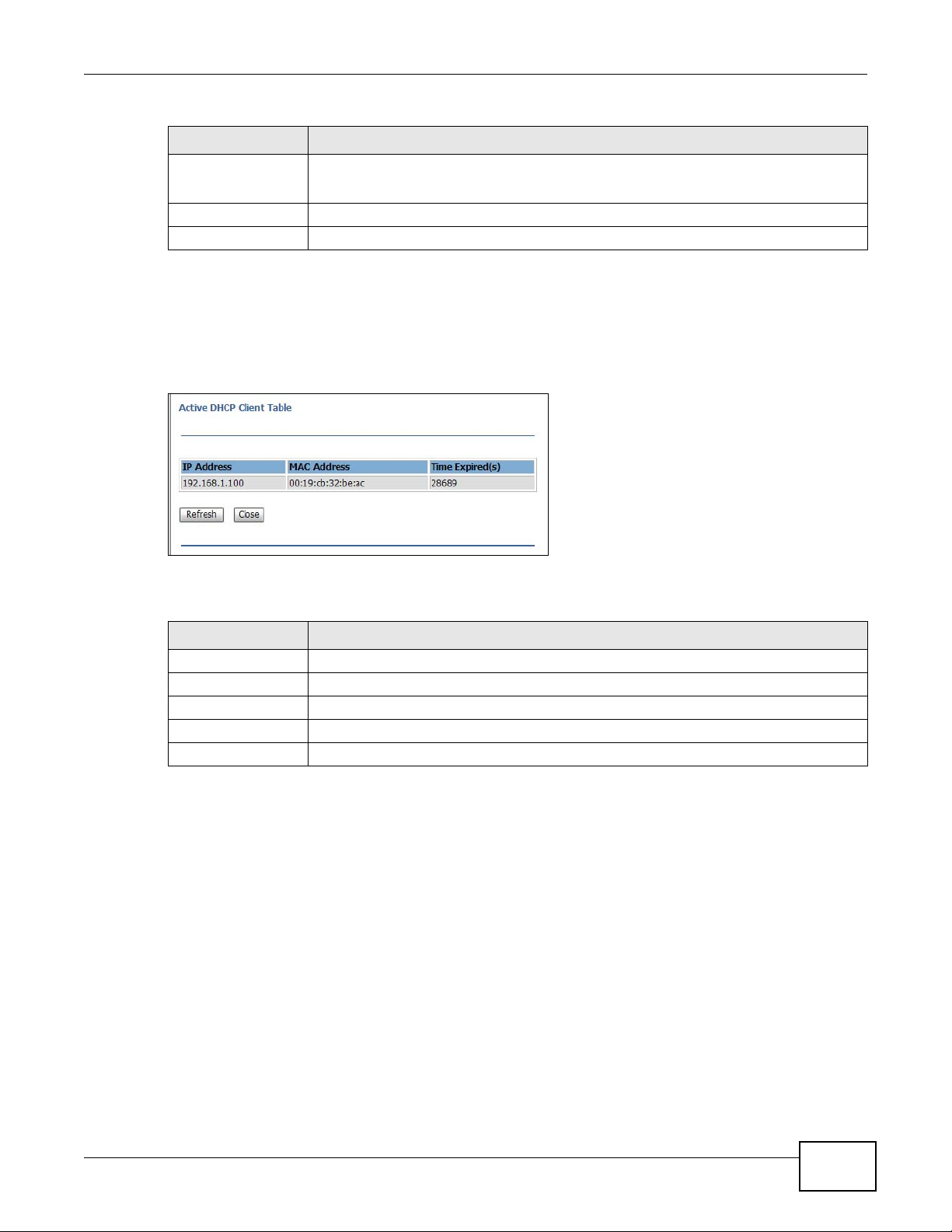
Table 31 Network > LAN (continued)
LABEL DESCRIPTION
Show Clients Click this to show the IP addresses that have been issued by the DHCP server.
This field is not configurable when DHCP server is disabled.
Apply Changes Click this to save changes back to the NBG2105.
Reset Click this to begin configuring this screen afresh.
9.4.1 Active DHCP Client Screen
Use this screen to view which DHCP clients have accepted their IP configuration from the NBG2105.
Click Network > LAN, and then Show Clients.
Figure 42 Network > LAN: Show Clients
Chapter 9 LAN
The following table describes the labels in this screen.
Table 32 Network > LAN: Show Clients
LABEL DESCRIPTION
IP Address This shows the IP address leased to a DHCP client.
MAC Address This shows the MAC address of the client that leased the IP address.
Time Expired (s) This shows how many seconds remain on the DHCP lease.
Refresh Click this to update the screen.
Close Click this to close this screen.
NBG2105 User’s Guide
71
Page 72

Chapter 9 LAN
72
NBG2105 User’s Guide
Page 73

10.1 Overview
This chapter discusses the NBG2105’s WAN screens. Use these screens to configure your NBG2105
for Internet access.
A WAN (Wide Area Network) connection is an outside connection to another network or the
Internet. It connects your private networks such as a LAN (Local Area Network) and other
networks, so that a computer in one location can communicate with computers in other locations.
10.2 What You Can Do
You can configure your WAN interface to access your ISP in the following ways.
CHAPTER 10
WAN
• Static IP allows you to configure all NBG2105 WAN IP configuration settings manually (Section
10.4.1 on page 74).
• DHCP Client allows the NBG2105 to get its IP configuration from a DHCP server (Section 10.4.2
on page 75).
• PPPoE allows the NBG2105 to connect via the Point-to-Point Protocol over Ethernet (Section
10.4.3 on page 76).
10.3 What You Need To Know
The information in this section can help you configure the screens for your WAN connection.
10.3.1 Configuring Your Internet Connection
Encapsulation Method
Encapsulation is used to include data from an upper layer protocol into a lower layer protocol. To set
up a WAN connection to the Internet, you need to use the same encapsulation method used by your
ISP (Internet Service Provider). If your ISP offers a dial-up Internet connection using PPPoE (PPP
over Ethernet), they should also provide a username and password (and service name) for user
authentication.
NBG2105 User’s Guide 73
Page 74

Chapter 10 WAN
WAN IP Address
The WAN IP address is an IP address for the NBG2105, which makes it accessible from an outside
network. It is used by the NBG2105 to communicate with other devices in other networks. It can be
static (fixed) or dynamically assigned by the ISP each time the NBG2105 tries to access the
Internet.
If your ISP assigns you a static WAN IP address, they should also assign you the subnet mask and
DNS server IP address(es) (and a gateway IP address if you use the Ethernet or ENET ENCAP
encapsulation method).
DNS Server Address Assignment
Use Domain Name System (DNS) to map a domain name to its corresponding IP address and vice
versa, for instance, the IP address of www.zyxel.com is 204.217.0.2. The DNS server is extremely
important because without it, you must know the IP address of a computer before you can access
it.
The NBG2105 can get the DNS server addresses in the following ways.
1 The ISP tells you the DNS server addresses, usually in the form of an information sheet, when you
sign up. If your ISP gives you DNS server addresses, manually enter them in the DNS server fields.
2 If your ISP dynamically assigns the DNS server IP addresses (along with the NBG2105’s WAN IP
address), set the DNS server fields to get the DNS server address from the ISP.
WAN MAC Address
The WAN port's MAC address can be configured by either using the factory default or cloning the
MAC address from a computer on your LAN. Choose Clear Mac Clone to select the factory assigned
default MAC Address.
Otherwise, press the Clone MAC address button on the side of the NBG2105 to clone the MAC
address of the computer connected to the NBG2105. Once it is successfully configured, the address
will be copied to configuration file. It is recommended that you clone the MAC address prior to
hooking up the WAN Port.
10.4 WAN Interface Setup
Click Network > WAN to change how your NBG2105’s WAN interface accesses your ISP. The
screen differs according to the WAN Access Type you choose.
10.4.1 Static IP
74
Select Static IP from WAN Access Type to configure all NBG2105 WAN IP configuration settings
manually.
NBG2105 User’s Guide
Page 75

Chapter 10 WAN
Figure 43 Network > WAN: Static IP
The following table describes the labels in this screen.
Table 33 Network > WAN: Static IP
LABEL DESCRIPTION
WAN Access Type Select Static IP to enable manual configuration of all NBG2105 IP settings.
Internet IP Address Enter the Internet-facing IP address.
Subnet Mask Enter the subnet mask of the NBG2105 WAN interface.
Default Gateway Enter the IP address of a default gateway to the Internet.
MTU Size Enter the MTU (Maximum Transmission Unit) size for each packet. If a larger packet
DNS 1 Enter the IP address of the primary DNS server.
DNS 2 (Optional) Enter the IP address of the secondary DNS server.
Clone MAC Address Enter the MAC address of the WAN interface.
arrives, the NBG2105 divides it into smaller fragments.
Clear Mac Clone Click this to reset the MAC address of the WAN interface to factory defaults.
Apply Changes Click this to save changes back to the NBG2105.
Reset Click this to begin configuring this screen afresh.
10.4.2 DHCP Client
Select DHCP Client from WAN Access Type to make the NBG2105 get its IP configuration from a
DHCP server.
NBG2105 User’s Guide
This field is available only when the NBG2105 is in router mode.
This field is available only when the NBG2105 is in router mode.
75
Page 76

Chapter 10 WAN
Figure 44 Network > WAN: DHCP Client
The following table describes the labels in this screen.
Table 34 Network > WAN: DHCP Client
LABEL DESCRIPTION
WAN Access Type Select DHCP Client to make the NBG2105 get its IP configuration from a DHCP server.
MTU Size Enter the MTU (Maximum Transmission Unit) size for each packet. If a larger packet
Attain DNS
Automatically
Set DNS Manually Select this to configure the NBG2105 to use DNS server addresses manually.
Clone MAC Address Enter the MAC address of the WAN interface.
arrives, the NBG2105 divides it into smaller fragments.
Select this to configure the NBG2105 to get addresses of DNS servers via DHCP.
DNS 1 Enter the IP address of the primary DNS server.
DNS 2
(Optional)
Enter the IP address of the secondary DNS server.
Clear Mac Clone Click this to reset the MAC address of the WAN interface to factory defaults.
Apply Changes Click this to save changes back to the NBG2105.
Reset Click this to begin configuring this screen afresh.
10.4.3 PPPoE
The NBG2105 supports PPPoE (Point-to-Point Protocol over Ethernet). PPPoE is an IETF standard
(RFC 2516) specifying how a personal computer (PC) interacts with a broadband modem (DSL,
cable, wireless, etc.) connection. The PPPoE option is for a dial-up connection using PPPoE.
For the service provider, PPPoE offers an access and authentication method that works with existing
access control systems (for example Radius).
One of the benefits of PPPoE is the ability to let you access one of multiple network services, a
function known as dynamic service selection. This enables the service provider to easily create and
offer new IP services for individuals.
76
This field is available only when the NBG2105 is in router mode.
This field is available only when the NBG2105 is in router mode.
NBG2105 User’s Guide
Page 77

Chapter 10 WAN
Operationally, PPPoE saves significant effort for both you and the ISP or carrier, as it requires no
specific configuration of the broadband modem at the customer site.
By implementing PPPoE directly on the NBG2105 (rather than individual computers), the computers
on the LAN do not need PPPoE software installed, since the NBG2105 does that part of the task.
Furthermore, with NAT, all of the LANs’ computers will have access.
Select PPPoE from WAN Access Type to make the NBG2105 get its IP configuration via PPPoE.
Figure 45 Network > WAN: PPPoE
The following table describes the labels in this screen.
Table 35 Network > WAN: PPPoE
LABEL DESCRIPTION
WAN Access Type Select PPPoE to make the NBG2105 get its IP configuration via PPPoE.
User Name Enter the user name provided by your ISP.
Password Enter the password provided by your ISP.
MTU Size Enter the MTU (Maximum Transmission Unit) size for each packet. If a larger packet
arrives, the NBG2105 divides it into smaller fragments.
Attain DNS
Automatically
Set DNS Manually Select this to configure the NBG2105 to use DNS server addresses manually.
DNS 1 Enter the IP address of the primary DNS server.
DNS 2
(Optional)
Clone MAC Address Enter the MAC address of the WAN interface.
Clear Mac Clone Click this to reset the MAC address of the WAN interface to factory defaults.
Apply Changes Click this to save changes back to the NBG2105.
Reset Click this to begin configuring this screen afresh.
Select this to configure the NBG2105 to get addresses of DNS servers via DHCP.
Enter the IP address of the secondary DNS server.
This field is available only when the NBG2105 is in router mode.
This field is available only when the NBG2105 is in router mode.
NBG2105 User’s Guide
77
Page 78

Chapter 10 WAN
78
NBG2105 User’s Guide
Page 79

11.1 Overview
Quality of Service (QoS) refers to both a network’s ability to deliver data with minimum delay, and
the networking methods used to control the use of bandwidth. Without QoS, all traffic data is
equally likely to be dropped when the network is congested. This can cause a reduction in network
performance and make the network inadequate for time-critical application such as video-ondemand.
Configure QoS on the NBG2105 to reserve bandwidth for certain traffic based on the IP address or
MAC address.
11.2 QoS Setup Screen
CHAPTER 11
Quality of Service (QoS)
Click Network > QoS to show the QoS Setup screen.
Figure 46 Network > QoS
NBG2105 User’s Guide 79
Page 80

Chapter 11 Quality of Service (QoS)
The following table describes the labels in this screen.
Table 36 Network > QoS
LABEL DESCRIPTION
QoS Setup
Enable QoS Select this to enable QoS.
Upstream
bandwidth (Kbps)
Downstream
bandwidth (Kbps)
QoS Rule Setting
Address Type Select IP to configure a QoS rule to match the source IP address of outgoing packets or
Local IP Address Enter the source IP address of outgoing packets or the destination IP address of
MAC Address Enter the source MAC address of outgoing packets or the destination MAC address of
Mode Select the mode for this rule: Guaranteed minimum bandwidth or restricted
Upstream
Bandwidth (Kbps)
Downstream
Bandwidth (Kbps)
Apply Changes Click this to save changes back to the NBG2105.
Reset Click this to begin configuring this screen afresh.
Current QoS Rules Table
Local IP Address This shows the source IP address of outgoing packets or the destination IP address of
MAC Address This shows the source MAC address of outgoing packets or the destination MAC address
Mode This shows the mode of this rule.
Upstream
Bandwidth
Downstream
Bandwidth
Select Click this to select this rule.
Delete Selected Click this to delete the selected rules.
Delete All Click this to delete all rules.
Reset Click this to reset all selections.
This shows the amount of upstream bandwidth for the WAN interface that you can
allocate using QoS.
The NBG2105 automatically sets this number to the WAN interface’s actual upstream
transmission speed.
This shows the amount of downstream bandwidth for the WAN interface that you can
allocate using QoS.
The NBG2105 automatically sets this number to the WAN interface’s actual downstream
transmission speed.
the destination IP address of incoming packets.
Select MAC to configure a QoS rule to match the source MAC address of outgoing
frames or the destination MAC address of incoming frames.
incoming packets that this QoS rule matches.
incoming packets that this QoS rule matches.
maximum bandwith.
Enter the maximum/guaranteed minimum bandwidth (according to the mode you
select) allowed for outgoing traffic that matches the IP address or MAC address you
specified.
Enter the maximum/guaranteed minimum bandwidth (according to the mode you
select) allowed for incoming traffic that matches the IP address or MAC address you
specified.
incoming packets that this QoS rule matches.
of incoming packets that this QoS rule matches.
This shows the uplink bandwidth that this rule enforces according to the Mode.
This shows the downlink bandwidth that this rule enforces according to the Mode.
80
NBG2105 User’s Guide
Page 81

CHAPTER 12
12.1 Overview
DDNS services let you use a domain name with a dynamic IP address.
12.2 What You Need To Know
The following terms and concepts may help as you read through this chapter.
What is DDNS?
Dynamic Domain Name Service (DDNS) services let you use a fixed domain name with a dynamic
IP address. Users can always use the same domain name instead of a different dynamic IP address
that changes each time to connect to the NBG2105 or a server in your network.
Dynamic DNS (DDNS)
Note: The NBG2105 must have a public global IP address and you should have your
registered DDNS account information on hand.
12.3 Dynamic DNS
To change your NBG2105’s DDNS, click Network > Dynamic DNS.
Figure 47 Network > Dynamic DNS
NBG2105 User’s Guide 81
Page 82

Chapter 12 Dynamic DNS (D DNS)
The following table describes the labels in this screen.
Table 37 Network > Dynamic DNS
LABEL DESCRIPTION
Enable DDNS Click this to enable dynamic DNS.
Service Provider Select the name of your Dynamic DNS service provider.
Domain Name Enter the domain name assigned by your service provider to your NBG2105.
Username/Email Enter the user name assigned by your service provider to your NBG2105. If you’ve
Password/Key Enter the password assigned by your service provider to your NBG2105. If you’ve
Apply Changes Click this to save changes back to the NBG2105.
Reset Click this to begin configuring this screen afresh.
selected TZO in the Service Provider field, enter the user name you registered with
the service provider.
selected TZO in the Service Provider field, enter the key you registered with the
service provider.
82
NBG2105 User’s Guide
Page 83

13.1 Overview
This chapter discusses how to configure the wireless network settings in your NBG2105. See the
appendices for more detailed information about wireless networks.
The following figure provides an example of a wireless network.
Figure 48 Example of a Wireless Network
CHAPTER 13
Wireless LAN
The wireless network is the part in the blue circle. In this wireless network, devices A and B are
called wireless clients. The wireless clients use the access point (AP) to interact with other devices
(such as the printer) or with the Internet. Your NBG2105 is the AP.
13.1.1 What You Can Do
•Use the Basic screen to turn the wireless connection on or off and make other basic
configuration changes (Section 13.2 on page 86).
•Use the Advanced screen to configure wireless advanced features, such as the output power
and set the RTS/CTS Threshold (Section 13.4 on page 88).
•Use the Security screen to set up wireless security between the NBG2105 and the wireless
clients (Section 13.5 on page 89).
NBG2105 User’s Guide 83
Page 84

Chapter 13 Wireless LAN
•Use the Site Survey screen to scan for and connect to a wireless network automatically. (Section
13.6 on page 92)
•Use the WPS screen to quickly set up a wireless network with strong security, without having to
configure security settings manually (Section 13.8 on page 95).
•Use the MAC Filtering screen to allow or deny wireless stations based on their MAC addresses
from connecting to the NBG2105 (Section 13.9 on page 97).
13.1.2 What You Should Know
Every wireless network must follow these basic guidelines.
• Every wireless client in the same wireless network must use the same SSID.
The SSID is the name of the wireless network. It stands for Service Set IDentity.
• If two wireless networks overlap, they should use different channels.
Like radio stations or television channels, each wireless network uses a specific channel, or
frequency, to send and receive information.
• Every wireless client in the same wireless network must use security compatible with the AP.
Security stops unauthorized devices from using the wireless network. It can also protect the
information that is sent in the wireless network.
Wireless Security Overview
The following sections introduce different types of wireless security you can set up in the wireless
network.
SSID
Normally, the AP acts like a beacon and regularly broadcasts the SSID in the area. You can hide the
SSID instead, in which case the AP does not broadcast the SSID. In addition, you should change
the default SSID to something that is difficult to guess.
This type of security is fairly weak, however, because there are ways for unauthorized devices to
get the SSID. In addition, unauthorized devices can still see the information that is sent in the
wireless network.
Authentication
Authentication is the process of confirming a client’s user name and password when they connect to
a network. Turning off authentication means allowing anyone to connect to the network.
Encryption
Wireless networks can use encryption to protect the information that is sent in the wireless
network. It is the process of taking data and encoding it, usually using a secret code, so that it
becomes unreadable unless decrypted with the proper code or pass phrase. If you do not know the
secret code, you cannot understand the message.
84
NBG2105 User’s Guide
Page 85

Chapter 13 Wireless LAN
WEP
Data Encryption
WEP (Wired Equivalent Privacy) encryption scrambles all data packets transmitted between the
NBG2105 and the AP or other wireless stations to keep network communications private. Both the
wireless stations and the access points must use the same WEP key for data encryption and
decryption.
Authentication Type
The IEEE 802.11b/g/n standard describes a simple authentication method between the wireless
stations and AP. Three authentication types are defined: Both, Open and Shared.
• Open mode is implemented for ease-of-use and when security is not an issue. The wireless
station and the AP or peer computer do not share a secret key. Thus the wireless stations can
associate with any AP or peer computer and listen to any transmitted data that is not encrypted.
• Shared mode involves a shared secret key to authenticate the wireless station to the AP or peer
computer. This requires you to enable the wireless LAN security and use same settings on both
the wireless station and the AP or peer computer.
• Both authentication mode allows the NBG2105 to switch between the open system and shared
key modes automatically. Use this mode if you do not know the authentication mode of the other
wireless stations.
WPA-PSK and WPA2-PSK
Wi-Fi Protected Access (WPA) is a subset of the IEEE 802.11i standard. WPA2 (IEEE 802.11i) is a
wireless security standard that defines stronger encryption, authentication and key management
than WPA.
Key differences between WPA(2) and WEP are improved data encryption and user authentication.
Both WPA and WPA2 improve data encryption by using Temporal Key Integrity Protocol (TKIP),
Message Integrity Check (MIC) and IEEE 802.1x. WPA and WPA2 use Advanced Encryption
Standard (AES) in the Counter mode with Cipher block chaining Message authentication code
Protocol (CCMP) to offer stronger encryption than TKIP.
The encryption mechanisms used for WPA(2) and WPA(2)-PSK are the same. The only difference
between the two is that WPA(2)-PSK uses a simple common password, instead of user-specific
credentials. The common-password approach makes WPA(2)-PSK susceptible to brute-force
password-guessing attacks but it’s still an improvement over WEP as it employs a consistent,
single, alphanumeric password to derive a PMK which is used to generate unique temporal
encryption keys. This prevent all wireless devices sharing the same encryption keys. (a weakness of
WEP)
If both an AP and the wireless clients support WPA2-PSK, use WPA2-PSK for stronger data
encryption. If the AP or the wireless clients do not support WPA2-PSK, just use WPA-PSK. Select
WEP only when the AP and/or wireless clients do not support WPA-PSK or WPA2-PSK. WEP is less
secure than WPA-PSK or WPA2-PSK.
NBG2105 User’s Guide
85
Page 86

Chapter 13 Wireless LAN
MAC Address Filter
Every wireless client has a unique identification number, called a MAC address.1 A MAC address is
usually written using twelve hexadecimal characters
00:A0:C5:00:00:02. To get the MAC address for each wireless client, see the appropriate User’s
Guide or other documentation.
You can use the MAC address filter to tell the AP which wireless clients are allowed or not allowed to
use the wireless network. If a wireless client is allowed to use the wireless network, it still has to
have the correct settings (SSID, channel, and security). If a wireless client is not allowed to use the
wireless network, it does not matter if it has the correct settings.
This type of security does not protect the information that is sent in the wireless network.
Furthermore, there are ways for unauthorized devices to get the MAC address of an authorized
wireless client. Then, they can use that MAC address to use the wireless network.
2
; for example, 00A0C5000002 or
WPS
WiFi Protected Setup (WPS) is an industry standard specification, defined by the WiFi Alliance. WPS
allows you to quickly set up a wireless network with strong security, without having to configure
security settings manually. Depending on the devices in your network, you can either press a
button (on the device itself, or in its configuration utility) or enter a PIN (Personal Identification
Number) in the devices. Then, they connect and set up a secure network by themselves. See how
to set up a secure wireless network using WPS in the Section 8.2 on page 59.
13.2 Wireless Basic Screen
Click Wireless LAN > Basic to make basic wireless configuration changes.
Figure 49 Wireless LAN > Basic
1. Some wireless devices, such as scanners, can detect wireless networks but cannot use wireless networks. These kinds
of wireless devices might not have MAC addresses.
2. Hexadecimal characters are 0, 1, 2, 3, 4, 5, 6, 7, 8, 9, A, B, C, D, E, and F.
86
NBG2105 User’s Guide
Page 87

Chapter 13 Wireless LAN
The following table describes the labels in this screen.
Table 38 Wireless LAN > Basic
LABEL DESCRIPTION
Disable Wireless
LAN Interface
Network Mode Select the frequency band and wireless network mode for your network.
SSID Enter the SSID (Service Set IDentity) to identify the service set with which wireless
Channel
Bandwidth
Channel
Selection
Broadcast SSID Select Enab led to broadcast the SSID or Disabled to hide the SSID in the outgoing
Show Active
Clients
Apply Changes Click this to save changes back to the NBG2105.
Reset Click this to begin configuring this screen afresh.
Select this to disable the wireless LAN interface.
clients are associated. Enter a descriptive name (up to 32 printable characters found on
a typical English language keyboard) for the wireless LAN.
Select the wireless channel width used by NBG2105.
A standard 20 MHz channel offers transfer speeds of up to 150 Mbps whereas a 40 MHz
channel uses two standard channels and offers speeds of up to 300 Mbps.
40 MHz (channel bonding or dual channel) bonds two adjacent radio channels to
increase throughput. The wireless clients must also support 40 MHz. It is often better to
use the 20 MHz setting in a location where the environment hinders the wireless signal.
Select 20MHz if you want to lessen radio interference with other wireless devices in
your neighborhood or the wireless clients do not support channel bonding.
Select a channel number. The channels you can select depend on the frequency band
and the country you are in.
beacon frame so a station cannot obtain the SSID through scanning using a site survey
tool.
Click this to show the clients connected to the NBG2105.
13.3 Active Wireless Clients Screen
Click Show Active Clients in Wireless LAN > Basic to show the clients connected to the
NBG2105.
Figure 50 Wireless LAN > Basic: Show Active Clients
NBG2105 User’s Guide
87
Page 88

Chapter 13 Wireless LAN
The following table describes the labels in this screen.
Table 39 Wireless LAN > Basic: Show Active Clients
LABEL DESCRIPTION
MAC Address This shows the MAC addresses of wireless clients associated with the NBG2105.
Mode This shows which wireless standard a wireless client is using to connect to the
Tx Packet This shows how many packets have been transmitted by the NBG2105 since
Rx Packet This shows how many packets have been received by the NBG2105 since association.
Tx Rate (Mbps) This shows the rate at which packets are being sent by the NBG2105 to this client.
Power Saving This shows whether power saving is turned on for this wireless client.
Expired Time (s) This shows when the association with this client6 will expire.
Refresh Click this to update the screen.
Close Click this to close this screen.
NBG2105.
association.
13.4 Advanced Wireless Settings Screen
Click Wireless LAN > Advanced to make advanced wireless configuration changes.
Figure 51 Wireless LAN > Advanced
The following table describes the labels in this screen.
Table 40 Wireless LAN > Advanced
LABEL DESCRIPTION
Fragment Threshold The threshold (number of bytes) for the fragmentation boundary for directed
RTS Threshold Data with its frame size larger than this value will perform the RTS (Request To Send)/
messages. It is the maximum data fragment size that can be sent.
This field is not configurable and the NBG2105 automatically changes to use the
maximum value if you select 2.4 GHz (N), 2.4 GHz (G + N) or 2.4 GHz (B + G + N)
in the Wireless LAN > Basic screen.
CTS (Clear To Send) handshake.
This field is not configurable and the NBG2105 automatically changes to use the
maximum value if you select 2.4 GHz (N), 2.4 GHz (G + N) or 2.4 GHz (B + G + N)
in the Wireless LAN > Basic screen.
88
NBG2105 User’s Guide
Page 89

Table 40 Wireless LAN > Advanced (continued)
LABEL DESCRIPTION
Beacon Interval Enter a value to configure how often beacon frames are broadcast.
Preamble Type Select Short Preamble for better performance or Long Preamble for better
compatibility.
20/40MHz Coexist Select Enabled to allow the NBG2105 to adjust the channel bandwidth automatically.
RF Output Power Set the output power of the NBG2105 in this field. If there is a high density of APs in an
area, decrease the output power of the NBG2105 to reduce interference with other APs.
Select one of the following 100%, 70%, 50%, 35% or 15%.
Apply Changes Click this to save changes back to the NBG2105.
Reset Click this to begin configuring this screen afresh.
13.5 Wireless Security
The screen varies depending on what you select in the Encryption field. Click Wireless LAN >
Security . This screen is not available when the NBG2105 is in Client mode.
Chapter 13 Wireless LAN
13.5.1 Disabled
Select Disabled to allow wireless clients to communicate with the access points without any data
encryption.
Note: If you do not enable any wireless security on your NBG2105, your network is
accessible to any wireless networking device that is within range.
Figure 52 Wireless LAN > Security: Disabled
NBG2105 User’s Guide
89
Page 90

Chapter 13 Wireless LAN
The following table describes the labels in this screen.
Table 41 Wireless LAN > Security: Disabled
LABEL DESCRIPTION
Encryption Select Disabled to allow any client to associate this network without authentication.
Apply Changes Click this to save changes back to the NBG2105.
Reset Click this to begin configuring this screen afresh.
13.5.2 WEP Encryption
Your NBG2105 allows you to configure up to four 64-bit or 128-bit WEP keys but only one key can
be enabled at any one time.
Select WEP from the Encryption list.
Figure 53 Wireless LAN > Security: WEP
90
The following table describes the labels in this screen.
Table 42 Wireless LAN > Security: WEP
LABEL DESCRIPTION
Encryption Select WEP to allow clients to associate this network with WEP authentication.
Key Length Select 64-bit or 128-bit.
This dictates the length of the security key that the network is going to use.
Key Format Select Hex to enter hexadecimal characters as a WEP key.
Select ASCII to enter ASCII characters as WEP key.
Encryption Key The WEP keys are used to encrypt data. Both the NBG2105 and the wireless stations
must use the same WEP key for data transmission.
If you chose 64-bit in the Key Format field, then enter any 5 ASCII characters or 10
hexadecimal characters ("0-9", "A-F").
If you chose 128-bit in the Key Format field, then enter 13 ASCII characters or 26
hexadecimal characters ("0-9", "A-F").
Show Password Select this to show the encryption key on the screen.
NBG2105 User’s Guide
Page 91

Table 42 Wireless LAN > Security: WEP (continued)
LABEL DESCRIPTION
Apply Changes Click this to save changes back to the NBG2105.
Reset Click this to begin configuring this screen afresh.
13.5.3 WPA-PSK/WPA2-PSK/WPA2-PSK Mixed
Select WPA-PSK, WPA2-PSK or WPA2-PSK Mixed from the Encryption list.
Figure 54 Wireless LAN > Security: WPA2-PSK Mixed
Chapter 13 Wireless LAN
The following table describes the labels in this screen.
Table 43 Wireless LAN > Security: WPA-PSK, WPA2-PSK or WPA2-PSK Mixed
LABEL DESCRIPTION
Encryption Select WPA-PSK, WPA2-PSK or WPA2-Mixed to allow clients to associate this
Pre-Shared Key
Format
Pre-Shared Key If Passphrase was selected in the Pre-Shared Key Format field, type a pre-shared
Show Password Select this to show the pre-shared key on the screen.
Apply Changes Click this to save changes back to the NBG2105.
Reset Click this to begin configuring this screen afresh.
network with WPA-PSK, WPA2-PSK or either WPA-PSK or WPA2-PSK authentication.
Select Passphrase to make the NBG2105 generate a key from a phrase typed into the
Pre-Shared Key field.
Select HEX to configure the NBG2105 to accept a key in hexadecimal format in the
Pre-Shared Key field.
key from 8 to 63 case-sensitive keyboard characters.
If HEX was selected in the Pre-Shared Key Format field, type a pre-shared key using
hexadecimal characters ("0-9", "A-F").
NBG2105 User’s Guide
91
Page 92
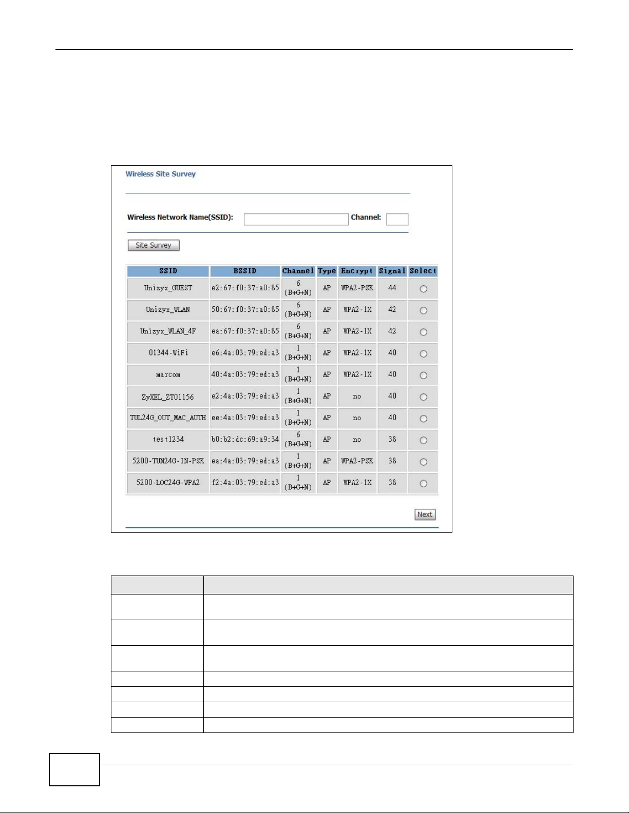
Chapter 13 Wireless LAN
13.6 Site Survey Screen
Use this screen to scan for and connect to a wireless network automatically. Go to Wir eless LAN >
Site Survey to open the following screen. This screen is available only when the NBG2105 is in
WISP+UR or Client mode.
Figure 55 Wireless LAN > Site Survey
92
The following table describes the labels in this screen.
Table 44 Wireless LAN > Site Survey
LABEL DESCRIPTION
Wireless Network
Name (SSID)
Channel Enter the channel number used by the wireless device to which the NBG2105 is
Site Survey Click this to search for available wireless devices within transmission range and update
SSID This shows the SSID of the wireless device.
BSSID This shows the MAC address of the wireless device.
Channel This shows the channel number and wireless standard used by this wireless device.
Type This shows the type of device found in the survey.
Enter the SSID of the AP to which you want the NBG2105 in WISP+UR mode or client
mode to connect.
connecting.
this table.
NBG2105 User’s Guide
Page 93
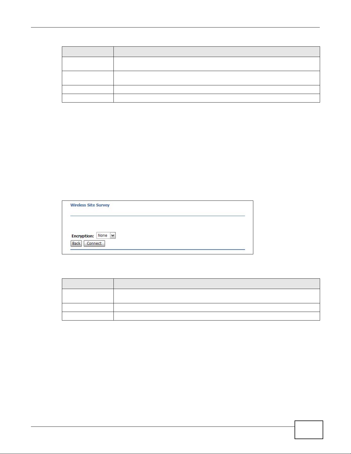
Table 44 Wireless LAN > Site Survey (continued)
LABEL DESCRIPTION
Encrypt This displays the data encryption and authentication method used by this wireless
device.
Signal This displays the strength of the wireless signal. The signal strength mainly depends on
the antenna output power and the distance between your NBG2105 and this device.
Select Click this to select a device.
Next Click this to open a screen to configure wireless security options.
13.7 Site Survey: Wireless Security
The screen varies depending on what you select in the Encryption field.
13.7.1 None
Select None if the NBG2105 can communicate with the selected access point without any data
encryption.
Chapter 13 Wireless LAN
Figure 56 Wireless LAN > Site Survey: None
The following table describes the labels in this screen.
Table 45 Wireless LAN > Site Survey: None
LABEL DESCRIPTION
Encryption Select None if the NBG2105 can communicate with the selected access point without
Back Click this to go back to the initial site survey screen.
Connect Click this to associate the NBG2105 with the selected access point.
13.7.2 WEP Encryption
Your NBG2105 can associate with APs that use 64-bit or 128-bit WEP keys but only one key can be
enabled at any one time.
any data encryption.
Select WEP from the Encryption list.
NBG2105 User’s Guide
93
Page 94

Chapter 13 Wireless LAN
Figure 57 Wireless LAN > Site Survey: WEP
The following table describes the labels in this screen.
Table 46 Wireless LAN > Site Survey: WEP
LABEL DESCRIPTION
Encryption Select WEP to associate with the selected AP using WEP authentication.
Key Type Select Open, Shared or Both.
Key Length Select 64-bit or 128-bit.
Key Format Select ASCII to enter ASCII characters as a WEP key.
This field specifies whether the NBG2105 must provide a WEP key to login to the
selected access point.
This dictates the length of the security key that selected access point is using.
Select Hex to enter hexadecimal characters as a WEP key.
Key Setting The WEP keys are used to encrypt data. Both the NBG2105 and the access point must
Back Click this to go back to the initial site survey screen.
Connect Click this to associate the NBG2105 with the selected access point.
use the same WEP key for data transmission.
If you chose 64-bit in the Key Format field, then enter any 5 ASCII characters or 10
hexadecimal characters ("0-9", "A-F").
If you chose 128-bit in the Key Format field, then enter 13 ASCII characters or 26
hexadecimal characters ("0-9", "A-F").
13.7.3 WPA-PSK/WPA2-PSK Encryption
Select WPA-PSK or WPA2-PSK from the Encryption list.
94
NBG2105 User’s Guide
Page 95

Chapter 13 Wireless LAN
Figure 58 Wireless LAN > Site Survey: WPA2-PSK
The following table describes the labels in this screen.
Table 47 Wireless LAN > Site Survey: WPA-PSK or WPA2-PSK
LABEL DESCRIPTION
Encryption Select WPA-PSK or WPA2-PSK to associate with the selected AP using WPA-PSK or
Authentication Mode Personal (Pre-Shared Key) is selected to use a simple common password for
WPA Cipher Suite Select TKIP and/or AES to configure which encryption options the NBG2105 uses to
WPA2 Cipher Suite Select TKIP and/or AES to configure which encryption options the NBG2105 uses to
Pre-Shared Key
Format
Pre-Shared Key If Passphrase was selected in the Pre-Shared Key Format field, type a pre-shared
Back Click this to go back to the initial site survey screen.
Connect Click this to associate the NBG2105 with the selected access point.
WPA2-PSK.
authentication.
connect to the selected access point. This appears when WPA encryption is selected.
connect to the selected access point. This appears when WPA2 encryption is selected.
Select Passphrase to make the NBG2105 generate a key from a phrase typed into the
Pre-Shared Key field.
Select HEX to configure the NBG2105 to accept a key in hexadecimal format in the
Pre-Shared Key field.
key from 8 to 63 case-sensitive keyboard characters.
If HEX was selected in the Pre-Shared Key Format field, type a pre-shared key using
hexadecimal characters ("0-9", "A-F").
13.8 WPS Screen
Use this screen to enable/disable WPS, view or generate a new PIN number and check current WPS
status. To open this screen, click Wireless LAN > WPS. The screen varies depending on the
operation mode in which the NBG2105 is working.
NBG2105 User’s Guide
95
Page 96

Chapter 13 Wireless LAN
Figure 59 Wireless LAN > WPS (Router, AP, or WISP+UR mode)
The following table describes the labels in this screen.
Table 48 Wireless LAN > WPS (Router, AP, or WISP+UR mode)
LABEL DESCRIPTION
Disable WPS Select this to turn off the WPS feature.
Apply Changes Click this to save changes back to the NBG2105.
Reset Click this to begin configuring this screen afresh.
WPS Status This displays Configured when the NBG2105 has connected to a wireless network
using WPS or when WPS is enabled and wireless or wireless security settings have been
changed. The current wireless and wireless security settings also appear in the screen.
This displays Unconfigured if WPS is disabled and there are no wireless or wireless
security changes on the NBG2105 or you click Release Configuration to remove the
configured wireless and wireless security settings.
Reset to
UnConfigured
Self PIN Number This is the WPS PIN (Personal Identification Number) of the NBG2105. Enter this PIN in
Start PBC Use this button when you use the PBC (Push Button Configuration) method to configure
Station PIN number Type the same PIN number generated in the wireless station’s utility. Then click Start
Start Use this button when you use the PIN Configuration method to configure wireless
Current Key Info.
Authentication This shows the current authentication method being used by WPS.
Encryption This shows the current encryption method being used by WPS.
Key This shows the current encryption key being used by WPS.
This button is only available when the WPS status displays Configured.
Click this button to remove all configured wireless and wireless security settings for
WPS connections on the NBG2105.
the configuration utility of the device you want to connect to the NBG2105 using WPS.
The PIN is not necessary when you use WPS push-button method.
wireless stations’s wireless settings.
Click this to start WPS-aware wireless station scanning and the wireless security
information synchronization.
to associate to each other and perform the wireless security information
synchronization.
station’s wireless settings.
96
NBG2105 User’s Guide
Page 97

Chapter 13 Wireless LAN
Figure 60 Wireless LAN > WPS (Client mode)
The following table describes the labels in this screen.
Table 49 Wireless LAN > WPS (Client mode)
LABEL DESCRIPTION
Disable WPS Select this to turn off the WPS feature.
Apply Changes Click this to save changes back to the NBG2105.
Reset Click this to begin configuring this screen afresh.
Self PIN Number This is the WPS PIN (Personal Identification Number) of the NBG2105. Enter this PIN in
the configuration utility of the device you want to connect to the NBG2105 using WPS.
The PIN is not necessary when you use WPS push-button method.
Start Use this button when the AP to which the NBG2105 is connecting uses the PIN
Configuration method to configure wireless station’s wireless settings.
Click Start to associate to each other and perform the wireless security information
synchronization.
Start PBC Use this button when the AP to which the NBG2105 is connecting uses the PBC (Push
Button Configuration) method to configure wireless stations’s wireless settings.
Click Start PBC to start WPS-aware wireless station scanning and the wireless security
information synchronization.
13.9 MAC Filtering Screen
The MAC filter screen allows you to configure the NBG2105 to give exclusive access to devices
(Allow Listed) or exclude devices from accessing the NBG2105 (Deny Listed). Every Ethernet
device has a unique MAC (Media Access Control) address. The MAC address is assigned at the
factory and consists of six pairs of hexadecimal characters, for example, 00:A0:C5:00:00:02. You
need to know the MAC address of the devices to configure this screen.
To change your NBG2105’s MAC filter settings, click Wireless LAN > MAC Filtering.
NBG2105 User’s Guide
97
Page 98

Chapter 13 Wireless LAN
Figure 61 Wireless LAN > MAC Filtering
The following table describes the labels in this screen.
Table 50 Wireless LAN > MAC Filtering
LABEL DESCRIPTION
Wireless Access
Control Mode
Select Disable to turn off MAC address filtering, or define the filter action for the list of
MAC addresses in the Current Access Control List.
Select Allow Listed to permit access to the NBG2105, MAC addresses not listed will be
denied access to the NBG2105.
Select Deny Listed to block access to the NBG2105, MAC addresses not listed will be
allowed to access the NBG2105.
MAC Address Enter the MAC address for this access control entry.
Comment Enter a description of this access control entry.
Apply Changes Click this to save changes back to the NBG2105.
Reset Click this to begin configuring this screen afresh.
Current Access Control List
MAC Address This shows the MAC address of the wireless station that is allowed or denied access to
the NBG2105.
Comment This shows a description of this access control entry.
Select Click this to select this rule.
Delete Selected Click this to delete the selected rules.
Delete All Click this to delete all rules.
Reset Click this to reset all selections.
98
NBG2105 User’s Guide
Page 99

14.1 Overview
This chapter shows you how to enable and configure the NBG2105 firewall settings.
The NBG2105 firewall is a packet filtering firewall and restricts access based on the source/
destination computer network address of a packet and the type of application.
14.2 What You Can Do
•Use the Port Filtering screen to apply filtering based on UDP or TCP port numbers (Section 14.4
on page 100).
•Use the IP Filtering screen to apply filtering based on IP addresses (Section 14.5 on page 101).
•Use the MAC Filtering to apply filtering based on MAC addresses (Section 14.6 on page 101).
•Use the URL Filtering to apply filtering based on URLs (Section 14.7 on page 102).
CHAPTER 14
Firewall
14.3 What You Need To Know
The following terms and concepts may help as you read through this chapter.
What is a Firewall?
A "firewall" is a system or group of systems that enforces an access-control policy between two
networks. Of course, firewalls cannot solve every security problem.
Guidelines For Enhancing Security
1 Change the default password via Web Configurator.
2 Think about access control before you connect to the network in any way, including attaching a
modem to the port.
3 Limit who can access your router.
4 Don't enable any local service (such as NTP) that you don't use. Any enabled service could present
a potential security risk. A determined hacker might be able to find creative ways to misuse the
enabled services to access the firewall or the network.
NBG2105 User’s Guide 99
Page 100

Chapter 14 Firewall
5 For local services that are enabled, protect against misuse. Protect by configuring the services to
communicate only with specific peers, and protect by configuring rules to block packets for the
services at specific interfaces.
6 Keep the NBG2105 in a secured (locked) room.
14.4 Port Filtering Screen
Click Firewall > Port Filtering to apply filtering based on UDP or TCP port numbers.
Figure 62 Firewall > Port Filtering
The following table describes the labels in this screen.
Table 51 Firewall > Port Filtering
LABEL DESCRIPTION
Enable Port Filtering Click this to apply filtering based on UDP or TCP port numbers.
Port Range Enter the port number or range of ports that define the traffic type. For example TCP
port 80 defines web traffic.
Protocol Select TCP to filter on TCP ports, UDP to filter on UDP ports or Both to filter on both
Comment Enter a description of this rule.
Apply Changes Click this to save changes back to the NBG2105.
Reset Click this to begin configuring this screen afresh.
Current Filter Table
Port Range This shows the port number or range of ports that define the traffic type. For example
Protocol This shows TCP for TCP port filtering, UDP for UDP port filtering or Both for TCP and
Comment Enter a description of this rule.
Select Click this to select this rule.
Delete Selected Click this to delete the selected rules.
Delete All Click this to delete all rules.
Reset Click this to reset all selections.
TCP and UDP ports.
TCP port 80 defines web traffic.
UDP port filtering.
100
NBG2105 User’s Guide
 Loading...