

Page 1
MAX-206M1R Series
WiMAX MIMO Indoor
Simple CPE
Default Login Details
IP Address: http://192.168.1.1
User Name: admin
Password: 1234
Firmware Version 3.70
Edition 2, 07/2009
www.zyxel.com
www.zyxel.com
Copyright © 2009
ZyXEL Communications Corporation
Page 2

Page 3

About This User's Guide
The following devices are covered in this book:
MODEL FEATURES
MAX-206M1R
MAX-216M1R
MAX-236M1R
MAX-216M1R plus
1 VoIP Port
1 LAN Port
2 External Antennas
1 VoIP Port
1 LAN Port
About This User's Guide
MAX-216MR
All graphics and Web Configurator screens shown in this book are based on the
MAX-206M1R unless otherwise noted.
1 LAN Port
Intended Audience
This manual is intended for people who want to configure the ZyXEL WiMAX
Modem using the web configurator. You s hould hav e at l east a basic knowledge of
TCP/IP networking concepts and topology.
Related Documentation
•Quick Start Guide
The Quick Start Guide is designed to help you get up and running right away. It
contains information on setting up your network and configuring for Internet
access.
• Web Configurator Online Help
Embedded web help for descriptions of individual screens and supplementary
information.
• Command Reference Guide
User’s Guide
The Command Reference Guide explains how to use the Command-Line
Interface (CLI) and CLI commands to configure the WiMAX Modem.
Note: It is recommended you use the web configurator to configure the WiMAX
Modem.
• Support Disc
Refer to the included CD for support documents.
3
Page 4

About This User's Guide
• ZyXEL Web Site
Please refer to www.zyxel.com
product certifications.
for additional support documentation and
User’s Guide Feedback
Help us help you. Send all User’s Guide-related comments, questions or
suggestions for improvement to the following address, or use e-mail instead.
Thank you!
The Technical Writing Team,
ZyXEL Communications Corp.,
6 Innovation Road II,
Science-Based Industrial Park,
Hsinchu, 300, Taiwan.
E-mail: techwriters@zyxel.com.tw
4
User’s Guide
Page 5

Document Conventions
Document Conventions
Warnings and Notes
These are how warnings and notes are shown in this User’s Guide.
Warnings tell you about things that could harm you or your
WiMAX Modem.
Note: Notes tell you other important information (for example, other things you may
need to configure or helpful tips) or recommendations.
Syntax Conventions
• The product(s) described in this book may be referred to as the “WiMAX
Modem”, the “device”, the “system” or the “product” in this User’s Guide.
• Product labels, screen names, field labels and field choices are all in bold font.
• A key stroke is denoted by square brackets and uppercase text, for example,
[ENTER] means the “enter” or “ret urn” key on your keyboard.
• “Enter” means for you to type one or more characters and then press the
[ENTER] key. “Select” or “choose” means for you to use one of the predefined
choices.
• A right angle bracket ( > ) within a screen name denotes a mouse click. For
example, TOOLS > Logs > Log Settings means you first click Tools in the
navigation panel, then the Logs sub menu and finally the Log Settings tab to
get to that screen.
• Units of measurement may denote the “metric” value or the “scientific” value.
For example, “k” for kilo may denote “1000” or “1024”, “M” for mega may
denote “1000000” or “1048576” and so on.
• “e.g.,” is a shorthand for “for instance”, and “i.e.,” means “that is” or “in other
words”.
User’s Guide
5
Page 6
Document Conventions
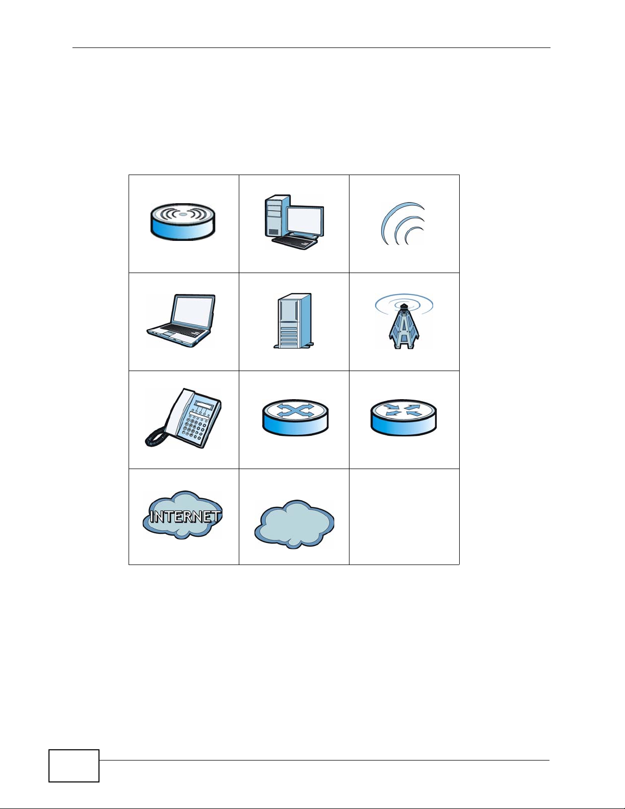
Icons Used in Figures
Figures in this User’s Guide may use the following generic icons. The WiMAX
Modem icon is not an exact representation of your WiMAX Modem.\
Table 1 Common Icons
WiMAX Access Point Computer Wireless Signal
Notebook Server WiMAX Base Station
Telephone Switch Router
Internet Cloud Internet/WiMAX
Cloud
6
User’s Guide
Page 7

Safety Warnings
Safety Warnings
For your safety, be sure to read and follow all warning notices and
instructions.
• Do NOT use this product near water, for example, in a wet basement or near a
swimming pool.
• Do NOT expose your device to dampness, dust or corrosive liquids.
• Do NOT store things on the device.
• Do NOT install, use, or service this device during a thunderstorm. There is a
remote risk of electric shock from lightning.
• Connect ONLY suitable accessories to the device.
• Do NOT open the device or unit. Opening or removing co vers can expose y ou to
dangerous high voltage points or other risks. ONLY qualified service personnel
should service or disassemble this device. Please contact your vendor for further
information.
• Make sure to connect the cables to the correct ports.
• Place connecting cables carefully so that no one will step on them or stumble
over them.
• Always disconnect all cables from this device before servicing or disassembling.
• Use ONLY an appropriate power adaptor or cord for your device. Connect it to
the right supply voltage (for example, 110V AC in North America or 230V AC in
Europe).
• Do NOT remove the plug and connect it to a power outlet by itself; always
attach the plug to the power adaptor first before connecting it to a power outlet.
• Do NOT allow anything to rest on the power adaptor or cord and do NOT place
the product where anyone can walk on the power adaptor or cord.
• Do NOT use the device if the power adaptor or cord is damaged as it might
cause electrocution.
• If the power adaptor or cord is damaged, remove it from the device and the
power source.
• Do NOT attempt to repair the power adaptor or cord. Contact your local vendor
to order a new one.Do not use the device outside, and make sure all the
connections are indoors. There is a remote risk of electric shock from lightning.
• Do NOT obstruct the device ventilation slots, as insufficient airflow may harm
your device.Use only No. 26 AWG (American Wire Gauge) or larger
telecommunication li ne cord.
User’s Guide
• Antenna Warning! This device meets ETSI and FCC certification requirements
when using the included antenna(s). Only use the included antenna(s).
• If you wal l mount your device, m ake sure that no electrical lines, gas or water
pipes will be damaged.
7
Page 8

Safety Warnings
• Make sure that the cable system is grounded so as to provide some protection
against voltage surges.
Your product is marked with this symbol, which is known as the WEEE mark.
WEEE stands for Waste Electronics and Electrical Equipment. It means that used
electrical and electronic products should not be mixed with general waste. Used
electrical and electronic equipment should be treated separately.
8
User’s Guide
Page 9

Contents Overview
Contents Overview
Introduction and Wizards ......................................................................................................29
Getting Started ........................................................................................................................... 31
Introducing the Web Configurator .............................................................................................. 37
Internet Connection Wizard....................................................................................................... 45
VoIP Connection Wizard ............................................................................................................ 51
Basic Screens ........................................................................................................................55
The Setup Screens .................................................................................................................... 57
Advanced Screens .................................................................................................................63
The LAN Configuration Screens ................................................................................................ 65
The WAN Configuration Screens ............................................................................................... 77
The NAT Configuration Screens ................................................................................................ 89
The System Configuration Screens ........................................................................................... 99
Voice Screens .......................................................................................................................109
The Service Configuration Screens ..........................................................................................111
The Phone Screens ................................................................................................................. 129
The Phone Book Screens ........................................................................................................ 139
Tools & Status Screens .......................................................................................................145
The Certificates Screens .........................................................................................................147
The Firewall Screens ............................................................................................................... 169
Content Filter ...................................... ... ... ... .... ... ... ... .............................................. ... ..............179
The Remote Management Screens ......................................................................................... 183
QoS ......................................................................................................................................... 195
The Logs Screens ................................................................................................................... 199
The Status Screen ................................................................................................................... 215
Troubleshooting and Specifications ..................................................................................227
Troubleshooting ..................................................... .................................................................. 229
Product Specifications ............................................................................................................. 237
Appendices and Index .........................................................................................................255
User’s Guide
9
Page 10

Contents Overview
10
User’s Guide
Page 11

Table of Contents
Table of Contents
About This User's Guide..........................................................................................................3
Document Conventions............................................................................................................5
Safety Warnings ........................................................................................................................7
Contents Overview ...................................................................................................................9
Table of Contents....................................................................................................................11
List of Figures.........................................................................................................................19
List of Tables...........................................................................................................................25
Part I: Introduction and Wizards........................................................... 29
Chapter 1
Getting Started........................................................................................................................31
1.1 About Your WiMAX Modem .................................................................................................31
1.1.1 WiMAX Internet Access .............................................................................................32
1.1.2 Make Calls via Internet Telephony Service Provider .................................................. 33
1.2 WiMAX Modem Hardware ................................................................................................... 34
1.2.1 LEDs ................................................ ... ... ... .... ... ... ............................................. ... ....... 34
1.3 Good Habits for Managing the Device ................................................................................. 36
Chapter 2
Introducing the Web Configurator ........................................................................................37
2.1 Overview ............. ............................................. ... .... ... ... ... .... ................................................ 37
2.1.1 Accessing the Web Configurator ................................................................................ 37
2.1.2 The Reset Button .......................................................................................................40
2.2 The Main Screen ................................................................................................................. 41
Chapter 3
Internet Connection Wizard...................................................................................................45
3.1 Overview ............. ............................................. ... .... ... ... ... .... ................................................ 45
User’s Guide
3.1.1 Welcome to the ZyXEL Setup Wizard ........................................................................45
3.1.2 System Information ................ ... ... .... ............................................. ... ... .... ... ... ... ... .... ... 46
3.1.3 Authentication Settings .............................................................................................. 47
3.1.4 IP Address ........................... ... ... ............................................. .... ... ... ... .... ... ................ 49
11
Page 12

Table of Contents
3.1.5 Setup Complete ......................................................... ............................................. ... 50
Chapter 4
VoIP Connection Wizard.........................................................................................................51
4.1 Overview ............. ............................................. ... .... ... ... ... .... ................................................ 51
4.2 Welcome to the ZyXEL Setup Wizard ................................................................................. 51
4.2.1 First Voice Account Settings ........ .... ... ............................................. ... .... ... ... ... ... .......52
4.2.2 Setup Complete ......................................................... ............................................. ... 54
Part II: Basic Screens............................................................................ 55
Chapter 5
The Setup Screens..................................................................................................................57
5.1 Overview ............. ............................................. ... .... ... ... ... .... ................................................ 57
5.1.1 What You Can Do in This Chapter ............................................................................. 57
5.1.2 What You Need to Know ..................................... ... .... ... ... ... ... .... ... ... .......................... 57
5.1.3 Before You Begin ......... .... ... ... ... ... .............................................................................. 58
5.2 Set IP Address .............. ............................................. ... ... .... ... ... ... ....................................... 58
5.3 DHCP Client ....... ... ............................................. .... ... ... ... .... ... ............................................. 59
5.4 Time Setting .................................................. ... ... .... ... ... ... .... ... ... .......................................... 60
5.4.1 Pre-Defined NTP Time Servers List .............................. ... ... ... .... ................................ 61
5.4.2 Resetting the Time . ... ... .... ... ... ... ............................................. .... ... ... ... .... ... ................ 62
Part III: Advanced Screens.................................................................... 63
Chapter 6
The LAN Configuration Screens............................................................................................65
6.1 Overview ............. ............................................. ... .... ... ... ... .... ................................................ 65
6.1.1 What You Can Do in This Chapter ............................................................................. 65
6.1.2 What You Need to Know ..................................... ... .... ... ... ... ... .... ... ... .......................... 65
6.2 DHCP Setup ....................................... ... .... ... ............................................. ... .... ... ... ... .......... 66
6.3 Static DHCP ..................................... ... ... .... ............................................. ... ... .... ... ................68
6.4 IP Static Route ..................................................................................................................... 69
6.4.1 IP Static Route Setup ................................................................................................. 70
6.5 Other Settings ........ ............................................. .... ... ... ... .................................................... 71
6.6 Technical Ref erence ........... ... .... ............................................. ... ... ... .... ... ... ... .... ... ... .............72
6.6.1 IP Address and Subnet Mask ..................................................................................... 72
6.6.2 DHCP Setup ..................... ... ... ... ... .... ... ... ... .............................................. ... ... ... ... .... ...73
6.6.3 LAN TCP/IP .................. .... ... ... ............................................. ... .... ... ............................. 73
6.6.4 DNS Server Address ................................. .... ... ... ... ............................................. .... ... 74
12
User’s Guide
Page 13

Table of Contents
6.6.5 RIP Setup ............................................................................... .... ... ... ... .... ... ... .............74
6.6.6 Multicast . ... ... ... .............................................. ... ... ... ............................................. ....... 75
Chapter 7
The WAN Configuration Screens...........................................................................................77
7.1 Overview ............. ............................................. ... .... ... ... ... .... ................................................ 77
7.1.1 What You Can Do in This Chapter ............................................................................. 77
7.1.2 What You Need to Know ..................................... ... .... ... ... ... ... .... ... ... .......................... 77
7.2 Internet Connection ......... ... ... .... ... ... ... ................................................................................. 80
7.3 WiMAX Configuration ......... ... .... ... ... ... ... .... ... ... ... ................................................. ... ... ..........82
7.3.1 Frequency Ranges ..................................................................................................... 84
7.3.2 Configuring Frequency Settings .................................................................................84
7.3.3 Using the WiMAX Frequency Screen ......................................................................... 85
7.4 Antenna Selection ........................................... ... .... ... ... ... .... ... ... ... ....................................... 86
7.5 Advanced ............ ............................................. ... .... ... ... .......................................................87
Chapter 8
The NAT Configuration Screens............................................................................................89
8.1 Overview ............. ............................................. ... .... ... ... ... .... ................................................ 89
8.1.1 What You Can Do in This Chapter ............................................................................. 89
8.2 General ............................ ... ... .... ... ... ............................................. ... .... ... ... ... ....................... 89
8.3 Port Forwarding ........................................ ... ... ... .... ... ... ... .... ................................................ 90
8.3.1 Port Forwarding Options ............................................................................................ 91
8.3.2 Port Forwarding Rule Setup ....................................................................................... 93
8.4 Trigger Port ............ ... .... ... ... ............................................. .... ... ... ... ... .... ................................ 94
8.4.1 Trigger Port Forwarding Example .............................................................................. 95
8.5 ALG ....................................... .............................................. ... ... ... ....................................... 96
Chapter 9
The System Configuration Screens......................................................................................99
9.1 Overview ............. ............................................. ... .... ... ... ... .... ................................................ 99
9.1.1 What You Can Do in This Chapter ............................................................................. 99
9.1.2 What You Need to Know ..................................... ... .... ... ... ... ... .... ... ... .......................... 99
9.2 General .............................. ... .... ... ... ... ... .............................................. ... ... ... .... ... ..............101
9.3 Dynamic DNS ..................................... ... .... ... ... ... .............................................. ... ... ... ........ 102
9.4 Firmware ................ ... .... ..................................................................................................... 104
9.4.1 The Firmware Upload Process ............ ............. ............. ............. ............. ......... ........ 105
9.5 Configuration ...... ... ... .... ... ... ............................................. .... ... ... ... ... .... .............................. 106
9.5.1 The Restore Configuration Process ......................................................................... 107
9.6 Restart ....................................... ... ... ... ... .... ... ... ............................................. .... ... ..............107
9.6.1 The Restart Process ................................................................................................ 108
User’s Guide
13
Page 14

Table of Contents
Part IV: Voice Screens......................................................................... 109
Chapter 10
The Service Configuration Screens.................................................................................... 111
10.1 Overview ...........................................................................................................................111
10.1.1 What You Can Do in This Chapter ..........................................................................111
10.1.2 What You Need to Know .........................................................................................111
10.1.3 Before you Begin .................................. .......... .......... ......... .......... .......... ......... ....... ..113
10.2 SIP Settings ......................................................................................................................113
10.2.1 Advanced SIP Settings ...........................................................................................115
10.3 QoS ................................................................................................................................. 122
10.4 Technical Reference ........................................................................................................123
10.4.1 SIP Call Progression ..............................................................................................123
10.4.2 SIP Client Server .................................................................................................... 124
10.4.3 SIP User Agent ...................................................................................................... 124
10.4.4 SIP Proxy Server ..................... .......... .......... ......... .......... .......... ......... ....... ......... ..... 124
10.4.5 SIP Redirect Server ............................................................................................... 125
10.4.6 NAT and SIP .......................................................................................................... 12 6
10.4.7 DiffServ .................................................................................................................. 126
10.4.8 DSCP and Per-Hop Behavior ................................................................................. 127
Chapter 11
The Phone Screens...............................................................................................................129
11.1 Overview .......................................................................................................................... 129
11.1.1 What You Can Do in This Chapter ......................................................................... 129
11.1.2 What You Need to Know ........................................................................................ 129
11.2 Analog Phone ..................................................................................................................130
11.2.1 Advanced Analog Phone Setup ............................................................................. 131
11.3 Common .......................................................................................................................... 132
11.4 Region .............................................................................................................................. 133
11.5 Technical Reference ........................................................................................................ 134
11.5.1 The Flash Key ........................................................................................................134
11.5.2 Europe Type Supplementary Phone Services ........................................................ 134
11.5.3 USA Type Supplementary Services ....................................................................... 136
Chapter 12
The Phone Book Screens.....................................................................................................139
12.1 Overview .......................................................................................................................... 139
12.1.1 What You Can Do in This Chapter ......................................................................... 139
12.1.2 What You Need to Know ........................................................................................ 139
12.2 Incoming Call Policy ........................................................................................................ 140
12.3 Speed Dial ....................................................................................................................... 142
14
User’s Guide
Page 15

Table of Contents
Part V: Tools & Status Screens........................................................... 145
Chapter 13
The Certificates Screens......................................................................................................147
13.1 Overview .......................................................................................................................... 147
13.1.1 What You Can Do in This Chapter ......................................................................... 147
13.1.2 What You Need to Know ........................................................................................ 147
13.2 My Certificates ................................................................................................................. 148
13.2.1 My Certificates Create .................... ............. ............. ............ ............. .......... ........... 150
13.2.2 My Certificate Edit ...... .... ... ... ... ... .... ... ..................................................................... 154
13.2.3 My Certificate Import ............................................................................................157
13.3 Trusted CAs ..................................................................................................................... 158
13.3.1 Trusted CA Edit ..................................................................................................... 160
13.3.2 Trusted CA Import ................................................................................................. 163
13.4 Technical Reference ........................................................................................................163
13.4.1 Certificate Authorities ............................................................................................. 164
13.4.2 Verifying a Certificate .............................................................................................166
Chapter 14
The Firewall Screens............................................................................................................169
14.1 Overview .......................................................................................................................... 169
14.1.1 What You Can Do in This Chapter ......................................................................... 169
14.1.2 What You Need to Know ........................................................................................ 169
14.2 Firewall Setting ................................................................................................................ 170
14.2.1 Firewall Rule Directions ......................................................................................... 170
14.2.2 Triangle Route ........................................................................................................ 171
14.2.3 Firewall Setting Options ......................................................................................... 172
14.3 Services ........................................................................................................................... 173
14.4 Technical Reference ........................................................................................................174
14.4.1 Stateful Inspection Firewall. ................................................................................... 174
14.4.2 Guidelines For Enhancing Security With Your Firewall .......................................... 175
14.4.3 The “Triangle Route” Problem ........................................... ................................ ..... 175
Chapter 15
Content Filter.........................................................................................................................179
15.1 Overview .......................................................................................................................... 179
15.1.1 What You Can Do in This Chapter ......................................................................... 179
15.2 Filter ................................................................................................................................. 180
15.3 Schedule .......................................................................................................................... 182
Chapter 16
The Remote Management Screens .....................................................................................183
16.1 Overview .......................................................................................................................... 183
User’s Guide
15
Page 16

Table of Contents
16.1.1 What You Can Do in This Chapter ......................................................................... 183
16.1.2 What You Need to Know ........................................................................................ 184
16.2 WWW .............................................................................................................................. 185
16.3 Telnet ............................................................................................................................... 186
16.4 FTP .................................................................................................................................. 186
16.5 SNMP .............................................................................................................................. 187
16.5.1 SNMP Traps ........................................................................................................... 188
16.5.2 SNMP Options .......................................................................................................189
16.6 DNS .................................................................................................................................190
16.7 Security ............................................................................................................................ 191
16.8 TR0-69 .............................................................................................................................192
Chapter 17
QoS.........................................................................................................................................195
17.1 Overview .......................................................................................................................... 195
17.2 General ............................................................................................................................195
17.3 Class Setup ..................................................................................................................... 196
17.3.1 Class Configuration ................................................................................................ 197
Chapter 18
The Logs Screens.................................................................................................................199
18.1 Overview .......................................................................................................................... 199
18.1.1 What You Can Do in This Chapter ......................................................................... 199
18.1.2 What You Need to Know ........................................................................................ 199
18.2 View Logs ........................................................................................................................ 201
18.3 Log Settings ..................................................................................................................... 203
18.4 Log Message Descriptions .............................................................................................. 205
Chapter 19
The Status Screen.................................................................................................................215
19.1 Overview .......................................................................................................................... 215
19.2 Status Screen .................................................................................................................. 215
19.2.1 Packet Statistics ..................................................................................................... 219
19.2.2 WiMAX Site Information ......................................................................................... 221
19.2.3 DHCP Table ........................................................................................................... 222
19.2.4 VoIP Statistics ........................................................................................................ 223
19.2.5 WiMAX Profile ........................................................................................................ 225
Part VI: Troubleshooting and Specifications .................................... 227
Chapter 20
Troubleshooting....................................................................................................................229
16
User’s Guide
Page 17

Table of Contents
20.1 Power, Hardware Connections, and LEDs .................................... .... ... ... ... ..................... 229
20.2 WiMAX Modem Access and Login .................................................................................. 230
20.3 Internet Access ................................................................................................................ 232
20.4 Phone Calls and VoIP ......................................................................................................234
20.5 Reset the WiMAX Modem to Its Factory Defaults ........................................................... 235
20.5.1 Pop-up Windows, JavaScripts and Java Permissions ........................................... 235
Chapter 21
Product Specifications.........................................................................................................237
21.1 Wall-Mounting ..................................................................................................................251
21.1.1 The Wall-Mounting Kit ............................................................................................ 251
21.1.2 Instructions ............................................................................................................. 251
Part VII: Appendices and Index.......................................................... 255
Appendix A WiMAX Security................................................................................................257
Appendix B Setting Up Your Computer’s IP Address...........................................................261
Appendix C Pop-up Windows, JavaScripts and Java Permissions......................................289
Appendix D IP Addresses and Subnetting...........................................................................299
Appendix E Importing Certificates........................................................................................311
Appendix F SIP Passthrough...............................................................................................343
Appendix G Common Services............................................................................................345
Appendix H Legal Information..............................................................................................349
Appendix I Customer Support..............................................................................................353
Index.......................................................................................................................................361
User’s Guide
17
Page 18

Table of Contents
18
User’s Guide
Page 19

List of Figures
List of Figures
Figure 1 Mobile Station and Base Station ........................ ... ... .... ... ............................................. ... .......... 32
Figure 2 WiMAX Modem’s VoIP Features - Peer-to-Peer Calls ............................................................. 33
Figure 3 WiMAX Modem’s VoIP Features - Calls via VoIP Service Provider ......................................... 33
Figure 4 The WiMAX Modem’s LEDs ..................................................................................................... 34
Figure 5 Main Screen ............................................................................................................................. 41
Figure 6 Select a Mode .......................................................................................................................... 45
Figure 7 Internet Connection Wizard > System Information ...................... ................................... .......... 46
Figure 8 Internet Connection Wizard > Authentication Settings Screen ................................................. 47
Figure 9 Internet Connection Wizard > IP Address ................................................................................ 49
Figure 10 Internet Connection Wizard > Complete ................................................................................50
Figure 11 Select a Mode ......................................................................................................................... 51
Figure 12 VoIP Connection > First Voice Account Settings ............................. .................................... ... 52
Figure 13 VoIP Connection > SIP Registration Test ............................................................................... 53
Figure 14 VoIP Connection > SIP Registration Fail ......................................................... ....................... 54
Figure 15 VoIP Connection > Finish ...................................................................................................... 54
Figure 16 SETUP > Set IP Address ....................................................................................................... 58
Figure 17 SETUP > Set IP Address ....................................................................................................... 59
Figure 18 SETUP > Time Setting ...........................................................................................................60
Figure 19 ADVANCED > LAN Configuration > DHCP Setup ................................................................. 66
Figure 20 ADVANCED > LAN Configuration > Static DHCP .................................................................. 68
Figure 21 Advanced> LAN Configuration > IP Static Route ................................................................... 69
Figure 22 Advanced> LAN Configuration > IP Static Route Setup ......................................................... 70
Figure 23 ADVANCED > LAN Configuration > Advanced ...................................................................... 71
Figure 24 WiMax: Mobile Station ............................................................................................................78
Figure 25 WiMAX: Multiple Mobile Stations ............................................... ... ... ... .... ... ... .......................... 78
Figure 26 Using an AAA Server ............................................................................................................. 79
Figure 27 ADVANCED > WAN Configuration > Internet Connection ..................................................... 80
Figure 28 ADVANCED > WAN Configuration >WiMAX Configuration ................................................ 83
Figure 29 Frequency Ranges ................................................................................................................. 84
Figure 30 Completing the WiMAX Frequency Screen ............................................................................ 86
Figure 31 ADVANCED > WAN Configuration > Antenna Selection ........................................................86
Figure 32 ADVANCED > WAN Configuration > Advanced ................................................................ 87
Figure 33 ADVANCED > NAT Configuration > General ......................................................................... 89
Figure 34 Multiple Servers Behind NAT Example ..................................................................................91
Figure 35 ADVANCED > NAT Configuration > Port Forwarding ...... ............. ............. ............. ............. ... 91
Figure 36 ADVANCED > NAT Configuration > Port Forwarding > Rule Setup ....................................... 93
Figure 37 ADVANCED > NAT Configuration > Trigger Port ...................................................................94
Figure 38 Trigger Port Forwarding Example ...........................................................................................95
User’s Guide
19
Page 20

List of Figures
Figure 39 ADVANCED > NAT Configuration > ALG ...............................................................................97
Figure 40 ADVANCED > System Configuration > General .................................................................. 101
Figure 41 ADVANCED > System Configuration > Dynamic DNS ......................................................... 103
Figure 42 ADVANCED > System Configuration > Firmware ................................................................ 104
Figure 43 ADVANCED > System Configuration > Configuration ..................................................... ..... 106
Figure 44 ADVANCED > System Configuration > Restart ......................................................... ...... ..... 107
Figure 45 VOICE > Service Configuration > SIP Setting .......................................................................113
Figure 46 STUN Example ......................................................................................................................115
Figure 47 VOICE > Service Configuration > SIP Settings > Advanced .................................................117
Figure 48 VOICE > Service Configuration > QoS ................................................................................ 122
Figure 49 SIP User Agent ............................. ... ... ... ... .... ... ... ................................................. ................. 124
Figure 50 SIP Proxy Server .......................................... ... ... ................................................. ................. 125
Figure 51 SIP Redirect Server ......................... ... ... ... .... ... ... ... .... ... ... ... .................................................. 126
Figure 52 DiffServ: Differentiated Service Field .................................................................................... 127
Figure 53 VOICE > Phone > Analog Phone .........................................................................................130
Figure 54 VOICE > Phone > Analog Phone > Advanced ....................... .............................................. 131
Figure 55 VOICE > Phone > Common ................................................................................................. 132
Figure 56 VOICE > Phone > Region .................................................................................................... 133
Figure 57 VOICE > Phone Book > Incoming Call Policy ...................................................................... 140
Figure 58 VOICE > Phone Book > Speed Dial ..................................................................................... 142
Figure 59 TOOLS > Certificates > My Certificates ............................................................................148
Figure 60 TOOLS > Certificates > My Certificates > Create ................................................................ 150
Figure 61 TOOLS > Certificates > My Certificates > Edit ............... ................................................ .... . 154
Figure 62 TOOLS > Certificates > My Certificates > Import ............ ... ............................................. .... . 157
Figure 63 TOOLS > Certificates > Trusted CAs ...................................................................................158
Figure 64 TOOLS > Certificates > Trusted CAs > Edit ...................................................................... 160
Figure 65 TOOLS > Certificates > Trusted CAs > Import .....................................................................163
Figure 66 Remote Host Certificates ..................................................................................................... 166
Figure 67 Certificate Details ................................................................................................................ 167
Figure 68 Firewall Rule Directions ........................................................................................................ 170
Figure 69 Ideal Firewall Setup .............................................................................................................. 171
Figure 70 TOOLS > Firewall > Firewall Setting ....................................................................................172
Figure 71 TOOLS > Firewall > Service Setting ....................................................................................173
Figure 72 “Triangle Route” Problem .....................................................................................................176
Figure 73 IP Alias ................................................................................................................................. 177
Figure 74 TOOLS > Content Filter > Filter ........................................................................................... 180
Figure 75 TOOLS > Content Filter > Schedule ....................................................................................182
Figure 76 TOOLS > Remote Management > WWW ............................................................................ 185
Figure 77 TOOLS > Remote Management > Telnet .............................................................................186
Figure 78 TOOLS > Remote Management > FTP ................................................................................ 186
Figure 79 SNMP Management Model ..................................................................................................187
Figure 80 TOOLS > Remote Management > SNMP ............................................................................189
Figure 81 TOOLS > Remote Management > DNS ............................................................................... 190
20
User’s Guide
Page 21

List of Figures
Figure 82 TOOLS > Remote Management > Security ......................................................................... 191
Figure 83 TR-069 Example .................................................................................................................. 192
Figure 84 TOOLS > Remote Management > TR069 ............................................................................ 193
Figure 85 QoS > General ..................................................................................................................... 195
Figure 86 QoS > Class Setup ............................................................................................................... 196
Figure 87 QoS > Class Setup > Class Configuration ........................................................................... 197
Figure 88 TOOLS > Logs > View Logs ................................................................................................. 201
Figure 89 TOOLS > Logs > Log Settings ............................................................................................. 203
Figure 90 Status ................................................................................................................................... 215
Figure 91 Packet Statistics ................................................................................................................... 219
Figure 92 WiMAX Site Information ......................................................................................................221
Figure 93 DHCP Table .......................................................................................................................... 222
Figure 94 VoIP Statistics .......................................................................................................................223
Figure 95 WiMAX Profile ..................................................................................................................... 225
Figure 96 Windows XP: Start Menu ...................................................................................................... 262
Figure 97 Windows XP: Control Panel ......................... ... ... ... ................................................. ... ... ........262
Figure 98 Windows XP: Control Panel > Network Connections > Properties ...................................... 263
Figure 99 Windows XP: Local Area Connection Properties .................................................................263
Figure 100 Windows XP: Internet Protocol (TCP/IP) Properties .......................................................... 264
Figure 101 Windows Vista: Start Menu ................................................................................................. 265
Figure 102 Windows Vista: Control Panel ............................................................................................ 265
Figure 103 Windows Vista: Network And Internet ................................................................................265
Figure 104 Windows Vista: Network and Sharing Center ..................................................................... 266
Figure 105 Windows Vista: Network and Sharing Center ..................................................................... 266
Figure 106 Windows Vista: Local Area Connection Properties ............................................................ 267
Figure 107 Windows Vista: Internet Protocol Version 4 (TCP/IPv4) Properties ................................... 268
Figure 108 Mac OS X 10.4: Apple Menu .............................................................................................. 269
Figure 109 Mac OS X 10.4: System Preferences ................................................................................. 269
Figure 110 Mac OS X 10.4: Network Preferences ................................................................................270
Figure 111 Mac OS X 10.4: Network Preferences > TCP/IP Tab. ........................................................ 270
Figure 112 Mac OS X 10.4: Network Preferences > Ethernet .............................................................. 271
Figure 113 Mac OS X 10.4: Network Utility .......................................................................................... 272
Figure 114 Mac OS X 10.5: Apple Menu .............................................................................................. 273
Figure 115 Mac OS X 10.5: Systems Preferences ............................................................................... 273
Figure 116 Mac OS X 10.5: Network Preferences > Ethernet .............................................................. 274
Figure 117 Mac OS X 10.5: Network Preferences > Ethernet .............................................................. 275
Figure 118 Mac OS X 10.5: Network Utility .......................................................................................... 276
Figure 119 Ubuntu 8: System > Administration Menu .......................................................................... 277
Figure 120 Ubuntu 8: Network Settings > Connections ...................... .... ............................................. . 277
Figure 121 Ubuntu 8: Administrator Account Authentication ................................................................ 278
Figure 122 Ubuntu 8: Network Settings > Connections ...................... .... ............................................. . 278
Figure 123 Ubuntu 8: Network Settings > Properties ........................................................................... 279
Figure 124 Ubuntu 8: Network Settings > DNS ...................................................................................280
User’s Guide
21
Page 22

List of Figures
Figure 125 Ubuntu 8: Network Tools .................................................................................................... 281
Figure 126 openSUSE 10.3: K Menu > Computer Menu ..................................................................... 282
Figure 127 openSUSE 10.3: K Menu > Computer Menu ..................................................................... 283
Figure 128 openSUSE 10.3: YaST Control Center .............................................................................. 283
Figure 129 openSUSE 10.3: Network Settings .................................................................................... 284
Figure 130 openSUSE 10.3: Network Card Setup ............................................................................... 285
Figure 131 openSUSE 10.3: Network Settings .................................................................................... 286
Figure 132 openSUSE 10.3: KNetwork Manager ................................................................................. 287
Figure 133 openSUSE: Connection Status - KNetwork Manager ........................................................ 287
Figure 134 Pop-up Blocker ................................................................................................................... 289
Figure 135 Internet Options: Privacy .................................................................................................... 290
Figure 136 Internet Options: Privacy .................................................................................................... 291
Figure 137 Pop-up Blocker Settings ..................................................................................................... 292
Figure 138 Internet Options: Security ................................................................................................... 293
Figure 139 Security Settings - Java Scripting ....................................................................................... 294
Figure 140 Security Settings - Java ......................................................................................................295
Figure 141 Java (Sun) .......................................................................................................................... 296
Figure 142 Mozilla Firefox: TOOLS > Options .............................. ............................................. ... ... ..... 296
Figure 143 Mozilla Firefox Content Security ......................................................................................... 297
Figure 144 Network Number and Host ID ............................................................................................300
Figure 145 Subnetting Example: Before Subnetting ....................................... ... .... ... ... ... ..................... 303
Figure 146 Subnetting Example: After Subnetting ....................................... ... ... .... ... ... ... ..................... 304
Figure 147 Conflicting Computer IP Addresses Example .................................................................... 309
Figure 148 Conflicting Computer IP Addresses Example .................................................................... 309
Figure 149 Conflicting Computer and Router IP Addresses Example ..................................................310
Figure 150 Internet Explorer 7: Certification Error ................................................................................312
Figure 151 Internet Explorer 7: Certification Error ................................................................................312
Figure 152 Internet Explorer 7: Certificate Error ........................ ................ ................ ................ ........... 313
Figure 153 Internet Explorer 7: Certificate ............................................................................................ 313
Figure 154 Internet Explorer 7: Certificate Import Wizard ....................................................................314
Figure 155 Internet Explorer 7: Certificate Import Wizard ....................................................................314
Figure 156 Internet Explorer 7: Certificate Import Wizard ....................................................................315
Figure 157 Internet Explorer 7: Select Certificate Store ............................... ... .....................................315
Figure 158 Internet Explorer 7: Certificate Import Wizard ....................................................................316
Figure 159 Internet Explorer 7: Security Warning ............................................ .......... ...... .......... ........... 316
Figure 160 Internet Explorer 7: Certificate Import Wizard ....................................................................317
Figure 161 Internet Explorer 7: Website Identification .................................. ............................. ........... 317
Figure 162 Internet Explorer 7: Public Key Certificate File ........................... ... ... .... ... ........................... 318
Figure 163 Internet Explorer 7: Open File - Security Warning ... ... ... ... .... ... ... ........................................ 318
Figure 164 Internet Explorer 7: Tools Menu ......................................................................................... 319
Figure 165 Internet Explorer 7: Internet Options .................................................................................. 319
Figure 166 Internet Explorer 7: Certificates .......................................................................................... 320
Figure 167 Internet Explorer 7: Certificates .......................................................................................... 320
22
User’s Guide
Page 23

List of Figures
Figure 168 Internet Explorer 7: Root Certificate Store .......................................................................... 320
Figure 169 Firefox 2: Website Certified by an Unknown Authority ....................................................... 322
Figure 170 Firefox 2: Page Info ............................................................................................................ 323
Figure 171 Firefox 2: Tools Menu ......................................................................................................... 324
Figure 172 Firefox 2: Options ............................................................................................................... 324
Figure 173 Firefox 2: Certificate Manager ...........................................................................................325
Figure 174 Firefox 2: Select File ........................... ................ ................. ................ ..............................325
Figure 175 Firefox 2: Tools Menu ......................................................................................................... 326
Figure 176 Firefox 2: Options ............................................................................................................... 326
Figure 177 Firefox 2: Certificate Manager ...........................................................................................327
Figure 178 Firefox 2: Delete Web Site Certificates ..............................................................................327
Figure 179 Opera 9: Certificate signer not found ................................................................................. 328
Figure 180 Opera 9: Security information .............................................................................................329
Figure 181 Opera 9: Tools Menu ..........................................................................................................330
Figure 182 Opera 9: Preferences ......................................................................................................... 331
Figure 183 Opera 9: Certificate manager ............................................................................................ 332
Figure 184 Opera 9: Import certificate ................................................................................................. 332
Figure 185 Opera 9: Install authority certificate ........................ ........................................................... 333
Figure 186 Opera 9: Install authority certificate ........................ ........................................................... 333
Figure 187 Opera 9: Tools Menu ..........................................................................................................334
Figure 188 Opera 9: Preferences ......................................................................................................... 334
Figure 189 Opera 9: Certificate manager ............................................................................................ 335
Figure 190 Konqueror 3.5: Server Authentication ................................................................................336
Figure 191 Konqueror 3.5: Server Authentication ................................................................................336
Figure 192 Konqueror 3.5: KDE SSL Information ................................................................................ 337
Figure 193 Konqueror 3.5: Public Key Certificate File ..................... ... .... ... ... ... ... .... ... ... ... .... ... ... ... ... .....338
Figure 194 Konqueror 3.5: Certificate Import Result ............................................................................338
Figure 195 Konqueror 3.5: Kleopatra ................................................................................................... 338
Figure 196 Konqueror 3.5: Settings Menu ............................................................................................ 340
Figure 197 Konqueror 3.5: Configure ................................................................................................... 340
User’s Guide
23
Page 24

List of Figures
24
User’s Guide
Page 25

List of Tables
List of Tables
Table 1 Common Icons ............................................................................................................................ 6
Table 2 The WiMAX Modem .................................................................................................................. 34
Table 3 Main > Icons ............................................................................................................................. 41
Table 4 Main .......................................................................................................................................... 42
Table 5 Internet Connection Wizard > System Information .. .... ... ... ... .... ............................................. ... 46
Table 6 Internet Connection Wizard > Authentication Settings Screen ................................................. 47
Table 7 Internet Connection Wizard > IP Address .......................................... ....................................... 49
Table 8 VoIP Connection > First Voice Account Settings ...................................................................... 52
Table 9 SETUP > Set IP Address .......................................................................................................... 59
Table 10 SETUP > Set IP Address ........................................................................................................ 59
Table 11 SETUP > Time Setting ............................................................................................................60
Table 12 Pre-defined NTP Time Servers ...............................................................................................62
Table 13 ADVANCED > LAN Configuration > DHCP Setup ........................ ... ... .................................... 67
Table 14 ADVANCED > LAN Configuration > Static DHCP ................................................................... 68
Table 15 Advanced> LAN Configuration > IP Static Route .................................................................... 69
Table 16 Advanced> LAN Configuration > IP Static Route .................................................................... 69
Table 17 Management > Static Route > IP Static Route > Edit .............................................................70
Table 18 ADVANCED > LAN Configuration > Other Settings ................................................................ 71
Table 19 ADVANCED > WAN Configuration > Internet Connection > ISP Parameters for Internet Access
80
Table 20 Radio Frequency Conversion ................................................................................................. 83
Table 21 ADVANCED > WAN Configuration >WiMAX Configuration .................................................... 83
Table 22 DL Frequency Example Settings ............................................................................................ 85
Table 23 ADVANCED > WAN Configuration > Advanced ..................................................................... 86
Table 24 ADVANCED > WAN Configuration > Advanced ..................................................................... 88
Table 25 ADVANCED > NAT Configuration > General .......................................................................... 90
Table 26 Advanced> VPN Transport > Customer Interface ................................................................... 92
Table 27 ADVANCED > NAT Configuration > Port Forwarding ............................................................. 92
Table 28 ADVANCED > NAT Configuration > Port Forwarding > Rule Setup ....................................... 93
Table 29 ADVANCED > NAT Configuration > Trigger Port .................................................................... 94
Table 30 ADVANCED > NAT Configuration > ALG ................................................................................ 97
Table 31 ADVANCED > System Configuration > General ................................................................... 101
Table 32 ADVANCED > System Configuration > Dynamic DNS ......................................................... 103
Table 33 ADVANCED > System Configuration > Firmware ................................................................. 105
Table 34 ADVANCED > System Configuration > Configuration ..........................................................106
Table 35 ADVANCED > System Configuration > Firmware ................................................................. 107
Table 36 VOICE > Service Configuration > SIP Setting .......................................................................114
Table 37 VOICE > Service Configuration > SIP Settings > Advanced .................................................117
User’s Guide
25
Page 26

List of Tables
Table 38 Custom Tones Details ............................................ .... ... ... ... .... ... ... ... ... .................................. 120
Table 39 VOICE > Service Configuration > Qo S .................. .... ... ... ... .... ... ... ... ..................................... 122
Table 40 SIP Call Progression .............. ... .... ... ... ... ... .... ... ... ... .... ...........................................................123
Table 41 VOICE > Phone > Analog Phone ..........................................................................................131
Table 42 VOICE > Phone > Analog Phone > Advanced ...................................................................... 132
Table 43 VOICE > Phone > Common ... ... .... ... ... ... ... .... ... ... ... .... ................................................ ... ... ..... 133
Table 44 VOICE > Phone > Region ................ ... ... ... .... ... ... ... .... ... ................................................ ........ 133
Table 45 European Type Flash Key Commands ................................................................................. 134
Table 46 USA Type Flash Key Commands ......................................................................................... 136
Table 47 VOICE > Phone Book > Incoming Call Policy ....................................................................... 140
Table 48 Advanced> LAN Configuration > IP Static Route .................................................................. 142
Table 49 VOICE > Phone Book > Speed Dial ......................................................................................143
Table 50 TOOLS > Certificates > My Certificates ................................................................................ 148
Table 51 TOOLS > Certificates > My Certificates ................................................................................ 148
Table 52 TOOLS > Certificates > My Certificates > Create ................................................................. 151
Table 53 TOOLS > Certificates > My Certificates > Edit ...................................................................... 154
Table 54 TOOLS > Certificates > My Certificates > Import ..................................................................157
Table 55 TOOLS > Certificates > Trusted CAs .................................................................................... 158
Table 56 TOOLS > Certificates > Trusted CAs .................................................................................... 158
Table 57 TOOLS > Certificates > Trusted CAs > Edit .......................................................................... 160
Table 58 TOOLS > Certificates > Trusted CAs Import ......................................................................... 163
Table 59 TOOLS > Firewall > Firewall Setting ..................................................................................... 172
Table 60 TOOLS > Firewall > Service Setting ..................................................................................... 173
Table 61 TOOLS > Content Filter > Filter ............................................................................................181
Table 62 TOOLS > Content Filter > Schedule ..................................................................................... 182
Table 63 Remote Management ........................................................................................................... 183
Table 64 TOOLS > Remote Management > WWW .............................................................................185
Table 65 TOOLS > Remote Management > Telnet ............................................................................. 186
Table 66 TOOLS > Remote Management > FTP ................................................................................ 187
Table 67 SNMP Traps .......................................................................................................................... 188
Table 68 TOOLS > Remote Management > SNMP ............................................................................. 189
Table 69 TOOLS > Remote Management > DNS ............................................................................... 190
Table 70 TOOLS > Remote Management > Security .......................................................................... 191
Table 71 TOOLS > Remote Management > TR069 ............................................................................ 193
Table 72 TOOLS > Remote Management > Security .......................................................................... 195
Table 73 QoS Class Setup ..................................................................................................................196
Table 74 QoS Class Setup ..................................................................................................................197
Table 75 Syslog Logs .......................................................................................................................... 200
Table 76 RFC-2408 ISAKMP Payload Types ...................................................................................... 200
Table 77 TOOLS > Logs > View Logs ................................................................................................. 201
Table 78 TOOLS > Logs > Log Settings .............................................................................................. 204
Table 79 System Error Logs ................................................................................................................ 205
Table 80 System Maintenance Logs .................................................................................................... 205
26
User’s Guide
Page 27

List of Tables
Table 81 Access Control Logs .............................................................................................................206
Table 82 TCP Reset Logs .................................................................................................................... 207
Table 83 Packet Filter Logs ................................................................................................................. 207
Table 84 ICMP Logs ............................................................................................................................ 208
Table 85 PPP Logs .............................................................................................................................. 208
Table 86 UPnP Logs ............................................................................................................................ 208
Table 87 Content Filtering Logs ........................................................................................................... 209
Table 88 Attack Logs ......................................................... ... .... ... ........................................................209
Table 89 Remote Management Logs ................................................................................................... 210
Table 90 ICMP Notes ...................................... ... ... ... .... ... ......................................................................211
Table 91 SIP Logs .......................... ... ... ... .... ... ... ... ............................................. .... ... ... ... .....................212
Table 92 RTP Logs .............................................................................................................................. 212
Table 93 FSM Logs: Caller Side ........................ ... ... .... ................................................ ... .... ... ... ...........213
Table 94 FSM Logs: Callee Side .............................................................. ... ... ... .... ... ... ... .... ... ... ...........213
Table 95 Lifeline Logs .......................................................................................................................... 213
Table 96 Status .................................................................................................................................... 216
Table 97 Packet Statistics .................................................................................................................... 220
Table 98 WiMAX Site Information ........................................................................................................ 221
Table 99 DHCP Table ..........................................................................................................................222
Table 100 VoIP Statistics ..................................................................................................................... 223
Table 101 The WiMAX Profile Screen ................................................................................................. 225
Table 102 Environmental and Hardware Specifications ...................................................................... 237
Table 103 Radio Specifications ............................................................................................................ 238
Table 104 Firmware Specifications ...................................................................................................... 238
Table 105 Standards Supported .......................................................................................................... 240
Table 106 Voice Features .................................................................................................................... 241
Table 107 Star (*) and Pound (#) Code Support .................................................................................. 243
Table 108 Environmental and Hardware Specifications ...................................................................... 243
Table 109 Radio Specifications ............................................................................................................ 244
Table 110 Firmware Specifications ...................................................................................................... 245
Table 111 Standards Supported ........................................................................................................... 246
Table 112 Voice Features .................................................................................................................... 248
Table 113 Star (*) and Pound (#) Code Support .................................................................................. 249
Table 114 IP Address Network Number and Host ID Example ............................................................ 300
Table 115 Subnet Masks ..................................................................................................................... 301
Table 116 Maximum Host Numbers ..................................................................................................... 301
Table 117 Alternative Subnet Mask Notation ....................................................................................... 302
Table 118 Subnet 1 .............................................................................................................................. 305
Table 119 Subnet 2 .............................................................................................................................. 305
Table 120 Subnet 3 ..............................................................................................................................305
Table 121 Subnet 4 ..............................................................................................................................305
Table 122 Eight Subnets ...................................................................................................................... 306
Table 123 24-bit Network Number Subnet Planning ............................................................................ 306
User’s Guide
27
Page 28

List of Tables
Table 124 16-bit Network Number Subnet Planning ............................................................................ 307
Table 125 Commonly Used Services ........................................ ... ... ... .... ... ........................................... 345
28
User’s Guide
Page 29

PART I
Introduction and
Wizards
Getting Started (31)
Introducing the Web Configurator (37)
Internet Connection Wizard (45)
VoIP Connection Wizard (51)
29
Page 30

30
Page 31

CHAPTER 1
Getting Started
The following devices are covered in this book:
MODEL FEATURES
MAX-206M1R
MAX-216M1R
MAX-236M1R
MAX-216M1R plus
MAX-216MR
1 VoIP Port
1 LAN Port
2 External Antennas
1 VoIP Port
1 LAN Port
1 LAN Port
All graphics and Web Configurator screens shown in this book are based on the
MAX-206M1R unless otherwise noted.
1.1 About Your WiMAX Modem
The WiMAX Modem has a built-in switch and one phone port. It allows you to
access the Internet by connecting to a WiMAX wireless network.
You can use a traditional analog t elephone to make Internet calls using the WiMAX
Modem’s Voice over IP (VoIP) communication capabilities.
You can configure firewall and content filtering as well as a host of other features.
The web browser-based Graphical User Interface (GUI), also known as the web
configurator, provides easy management.
See Chapter 21 on page 237 for a complete list of features for your model.
User’s Guide
31
Page 32
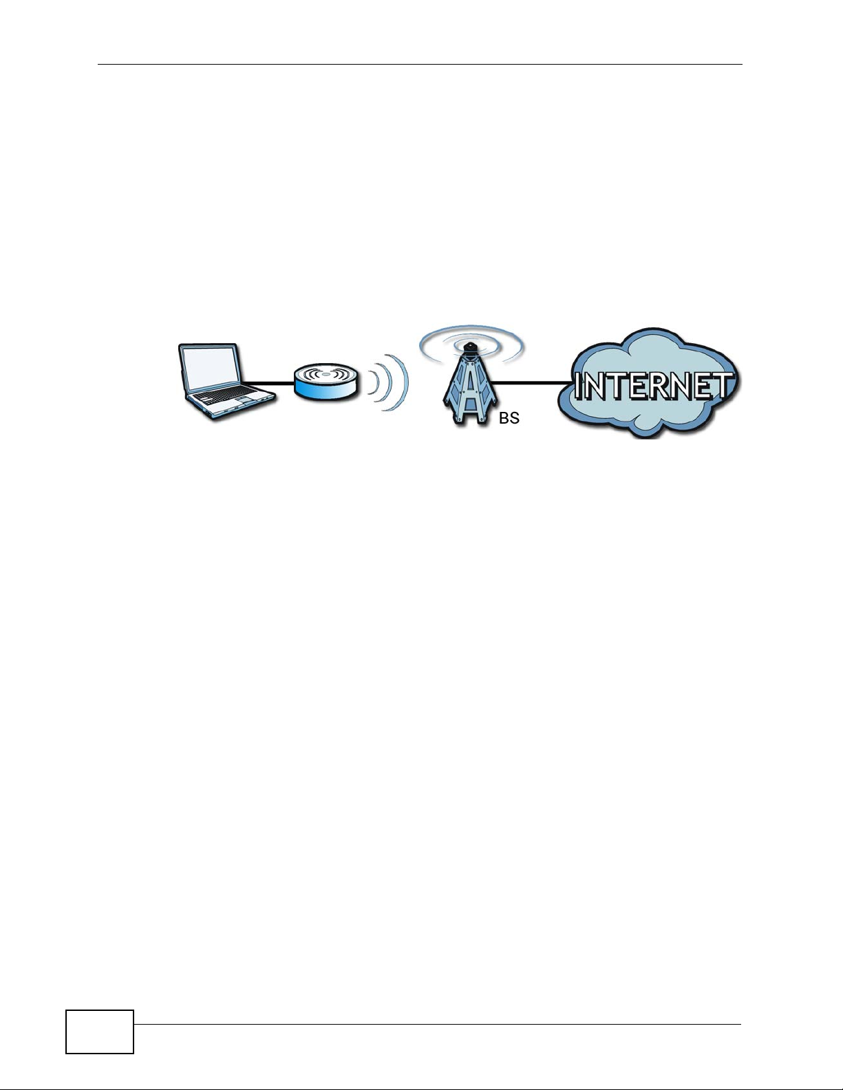
Chapter 1 Getting Started
1.1.1 WiMAX Internet Access
Connect your computer or network to the WiMAX Modem for WiMAX Internet
access. See the Quick Start Guide for instructions on hardware connection.
In a wireless metropolitan area network (MAN), the WiMAX Modem connects to a
WiMAX base station (BS) for Internet access.
The following diagram shows a notebook computer equipped with the WiMAX
Modem connecting to the Internet through a WiMAX base station (marked BS).
Figure 1 Mobile Station and Base Station
When the firewall is on, all inc o m ing traffic from the Internet to your network is
blocked unless it is initiated from your network.
Use content filtering to block access to web sites with URLs containing keywords
that you specify. You can define time periods and days during which content
filtering is enabled and include or exclude particular computers on your network
from content filtering. For example, you could bloc k access to certain web sites for
the kids.
32
User’s Guide
Page 33

Chapter 1 Getting Started
1.1.2 Make Calls via Internet Telephony Service Provider
In a home or small office environment, you can use the WiMAX Modem to make
and receive the following types of VoIP telephone calls:
• Peer-to-Peer calls - Use the WiMAX Modem to make a call directly to the
recipient’s IP address without using a SIP proxy server.
Figure 2 WiMAX Modem’s VoIP Features - Peer-to-Peer Calls
• Calls via a VoIP service provider - The WiMAX Modem sends your call to a VoIP
service provider’s SIP server which forwards your calls to either VoIP or PSTN
phones.
Figure 3 WiMAX Modem’s VoIP Features - Calls via VoIP Service Provider
User’s Guide
33
Page 34

Chapter 1 Getting Started
1.2 WiMAX Modem Hardware
Follow the instructions in the Quick Start Guide to make hardware connections.
1.2.1 LEDs
The following figure shows the LEDs (lights) on the WiMAX Modem.
Figure 4 The WiMAX Modem’s LEDs
POWER
WIMAX LINK
STRENGTH INDICATORS
VOICE
The following table describes your WiMAX Modem’s LEDs (from right to left).
Table 2 The WiMAX Modem
LED STATE DESCRIPTION
Power Off The WiMAX Modem is not receiving power.
Red The WiMAX Modem is receiving power but has been
unable to start up correctly or is not receiving
enough power. See the Troubleshooting section for
more information.
Green The WiMAX Modem is receiving power and
functioning correctly.
34
User’s Guide
Page 35

Chapter 1 Getting Started
Table 2 The WiMAX Modem
LED STATE DESCRIPTION
LAN Off The LAN is not connected.
Green The WiMAX Modem has a successful Local Area
Network (Ethernet) connection and is active during
modem activity.
Voice Off No SIP account is registered, or the WiMAX Modem
is not receiving power.
Green A SIP account is registered.
Green (Blinking) A SIP account is registered, and the phone attached
to the LINE port is in use (off the hook).
Yellow A SIP account is registered and has a voice
message on the SIP server.
Yellow (Blinking) A SIP account is registered and has a voice
message on the SIP server, and the phone attached
to the LINE port is in use (off the hook).
WiMAN Link Off The WiMAX Modem is not connected to a wireless
(WiMAX) network.
Green The WiMAX Modem is successfully connected to a
wireless (WiMAX) network.
Strength
Indicator
Green (Blinking
Slowly)
Green (Blinking
Quickly)
The Strength Indicator LEDs display the Received Signal Strength
Indication (RSSI) of the wireless (WiMAX) connection.
3 Signal LEDs The signal strength is greater than or equal to -70
2 Signal LEDs The signal strength is between -70 and -80 dBm
1 Signal LED The signal strength is between -80 and -90 dBm
0 Signal LEDs The signal strength is les than -90 dBm.
The WiMAX Modem is searching for a wireless
(WiMAX) network.
The WiMAX Modem has found a wireless (WiMAX)
network and is connecting.
dBm
User’s Guide
35
Page 36

Chapter 1 Getting Started
1.3 Good Habits for Managing the Device
Do the following things regularly to make the WiMAX Modem more secure and to
manage the WiMAX Modem more effectively.
• Change the password. Use a password that’s not easy to guess and that
consists of different types of characters, such as numbers and letters.
• Write down the password and put it in a safe place.
• Back up the configuration (and make sure you know how to restore it).
Restoring an earlier working configuration may be useful if the WiMAX Modem
becomes unstable or even crashes. If you forget yo ur password, you will have to
reset the WiMAX Modem to its factory default settings. If you backed up an
earlier configuration file, you would not have to totally re-configure the WiMAX
Modem. You could simply restore your last configuration.
36
User’s Guide
Page 37

CHAPTER 2
Introducing the Web
Configurator
2.1 Overview
The web configurator is an HTML-based management interface that allows easy
device set up and management via any web browser that supports: HTML 4.0,
CSS 2.0, and JavaScript 1.5, and higher. The recommended screen resolution for
using the web configurator is 1024 by 768 pixels and 16-bit color, or higher.
In order to use the web configurator you need to allow:
• Web browser pop-up windows from y our device. Web pop-up blocking is
enabled by default in many operating systems and web browsers.
• JavaScript (enabled by default in most web browsers).
• Java permissions (enabled by default in most web browsers).
See the Appendix C on page 289 for more information on configuring your web
browser.
2.1.1 Accessing the Web Configurator
1 Make sure your WiMAX Modem hardware is properly connected (refer to th e Quick
Start Guide for more information).
2 Launch your web browser.
3 Enter "192.168.1.1" as the URL.
User’s Guide
37
Page 38

Chapter 2 Introducing the Web Configurator
4 A password screen displays. The default password (“1234”) displays in non-
readable characters. If you haven’t changed the password yet, you can just click
Login. Click Cancel to revert to the default password in the password field. If you
have changed the password, enter your password and click Login.
5 The following screen displays if you have not yet changed your password. It is
highly recommended you change the default password. Enter a new password,
retype it to confirm and click Apply; alternatively click Ignore to proceed to the
main menu if you do not want to change the password now.
38
User’s Guide
Page 39

Chapter 2 Introducing the Web Configurator
6 Click Apply in the next screen to create a certificate using your WiMAX Modem’s
MAC address that will be specific to this device. This certificate is used for
authentication when using a secure HTTPS connection over the Internet.
7 A screen displays to let you choose to go to the Wizard or the Advanced screens.
•Click Go to Wizard setup if you are logging in for the first time or if you
want to make basic changes. The wizard selection screen appears after you
click Apply. See Chapter 3 on page 45 for more information.
•Click Go to Advanced setup if you want to configure features that are not
available in the wizards. The main screen appears after you click Apply.
See Section 3 on page 40 for more information.
•Click Exit if you want to log out.
User’s Guide
Note: For security reasons, the WiMAX Modem automatically logs you out if you do
not use the Web Configurator for five minutes. If this happens, log in again.
39
Page 40

Chapter 2 Introducing the Web Configurator
2.1.2 The Reset Button
If you forget your password or cannot access the web configurator, you will need
to use the Reset button to reload the factory-default configur ation file. This
means that you will lose all configurations that you had previously and the
password will be reset to “1234”.
2.1.2.1 Using The Reset Button
1 Make sure the Power light is on (not blinking).
2 To set the device back to the factory default settings, press the Reset button for
ten seconds or until the Power light begins to blink and then release it. When the
Power light begins to blink, the defaults have been restored and the device
restarts.
3 Reconfigure the WiMAX Modem following the steps in your Quick Start Guide.
40
User’s Guide
Page 41

2.2 The Main Screen
When you first log into the web configurator and by-pass the wizard, the Main
screen appears. Here you can view a summary of your WiMAX Modem connection
status. This is also the default “home” page for the ZyXEL web configurator and it
contains conveniently-placed shortcuts to all of the other screens.
Note: Some features in the web configurator may not be available depe ndin g on you r
firmware version and/or configuration.
Figure 5 Main Screen
Chapter 2 Introducing the Web Configurator
User’s Guide
The following table describes the icons in this screen.
Table 3 Main > Icons
ICON DESCRIPTION
MAIN
Click to return to the Main screen.
SETUP
Click to go the Setup screen, where you can configure LAN,
DHCP and WAN settings.
ADVANCED
Click to go to the Advanced screen, where you can configure
features like Port Forwarding and Triggering, SNTP and so on.
41
Page 42

Chapter 2 Introducing the Web Configurator
Table 3 Main > Icons (continued)
ICON DESCRIPTION
VOICE
Click to go to the Voice screen, where you can configure your
voice service and phone settings .
TOOLS
Click to go the Tools screen, where you can configure your
firewall, QoS, and content filter, among other things.
STATUS
Click to go to the Status screen, where you can view status and
statistical information for all connections and interfaces.
Strength Indicator
Displays a visual representation of the quality of your WiMAX
connection.
• Disconnected - Zero bars
• Poor reception - One bar
• Good reception - Two bars
• Excellent reception - Three bars
The following table describes the labels in this screen.
Table 4 Main
LABEL DESCRIPTION
Help Click to open the web configurator’s online help.
Wizard Click to run the Internet Connection and VoIP Connection Setup
Wizard. All of the settings that you can configure in this wizard
are also available in these web configurator screens.
Logout Click to log out of the web configurator.
Note: This does not log you off the WiMAX network, it simply
logs you out of the WiMAX Modem’s browser-based
configuration interface.
WiMAX Connection
Status
This field indicates the current status of your WiMAX connection.
Status messages are as follows:
• Connected - Indicates that the WiMAX Modem is connected
to the WiMAX network. Use the Strength Indicator icon to
determine the quality of your network connection.
• Disconnected - Indicates that the WiMAX Modem is not
connected to the WiMAX network.
• DL_SYN - Indicates a download synchronization is in
progress. This means the firmware is checking with the
server for any updates or settings alterations.
42
User’s Guide
Page 43

Chapter 2 Introducing the Web Configurator
Table 4 Main (continued)
LABEL DESCRIPTION
Software Version This field indicates the version number of the WiMAX Modem’s
firmware. The version number takes the form of:
Version(Build),release status (candidate) | Version Release
Date.
For example: V3.60(BCC.0)c4 | 07/08/2008 indicates that the
firmware is 3.60, build BCC.0, candidate4, released on July 08,
2008.
Version Date This field indicates the exact date and time the current firmware
was compiled.
System Uptime This field indicates how long the WiMAX Modem has been on.
This resets every time you shut the device down or restart it.
WiMAX Uptime This field indicates how long the WiMAX Modem has been
connected to the WiMAX network. This resets every time you
disconnect from the WiMAX network, shut the device down, or
restart it.
Voice 1 This field indicates the number and receiver status of the first
voice account.
User’s Guide
43
Page 44

Chapter 2 Introducing the Web Configurator
44
User’s Guide
Page 45
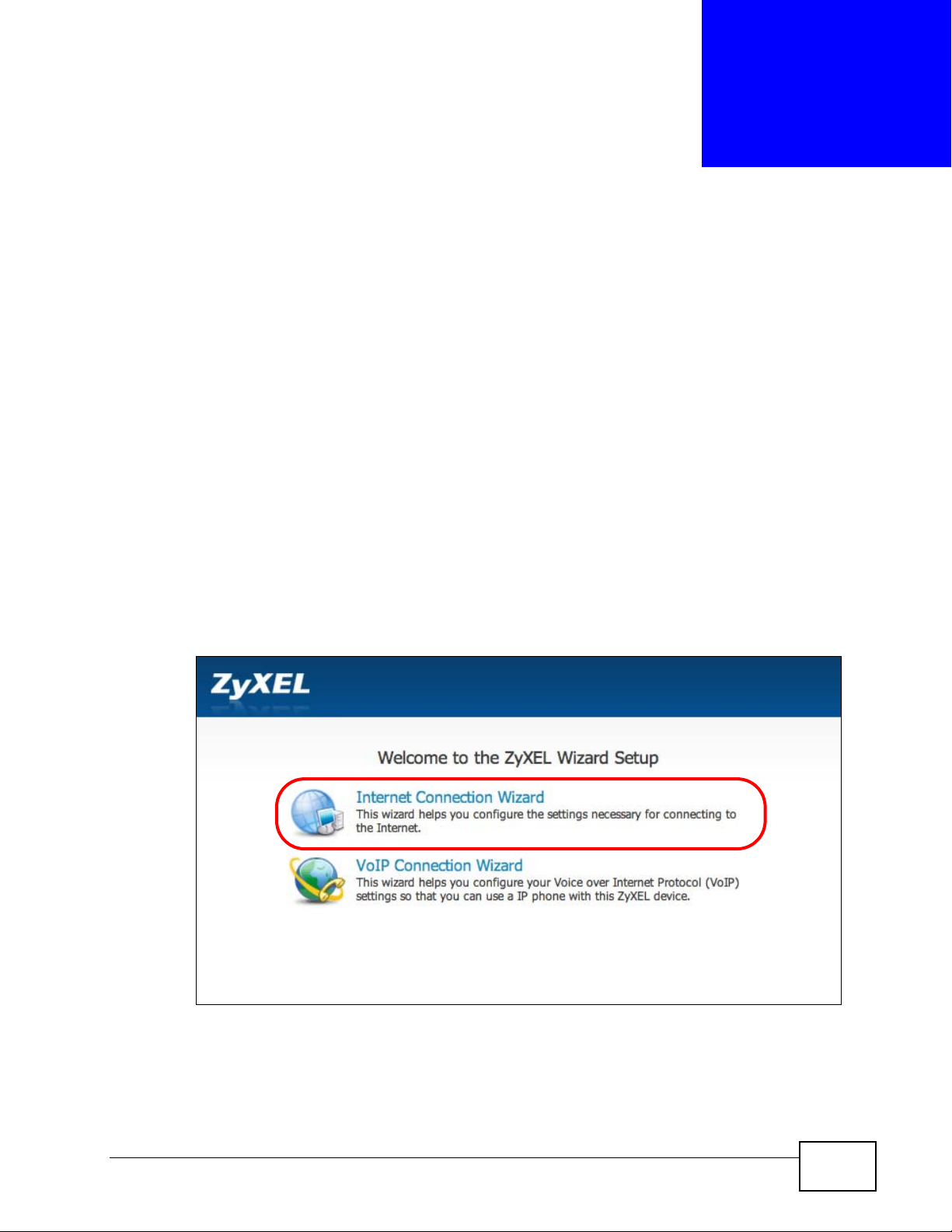
CHAPTER 3
Internet Connection Wizard
3.1 Overview
This chapter provides information on the ZyXEL Setup Wizard screens. The wizard
guides you through several steps where you can configure your Internet and V oIP
settings.
3.1.1 Welcome to the ZyXEL Setup Wizard
This is the welcome screen for the ZyXEL Setup Wizard. You can choose to either
configure your Internet connection or your VoIP connection.
The Internet Connection Wizard screens are described in detail in the following
sections.
Figure 6 Select a Mode
User’s Guide
45
Page 46

Chapter 3 Internet Connection Wizard
3.1.2 System Information
This Internet Connection Wizard screen allows you to configure your WiMAX
Modem’s system information. The settings here correspond to the ADVANCED >
System Configuration > General screen (see Section 9.2 on page 101 for
more).
Figure 7 Internet Connection Wizard > System Information
The following table describes the labels in this screen.
Table 5 Internet Connection Wizard > System Information
LABEL DESCRIPTION
System
Name
Domain
Name
Back Click to display the previous screen.
Next Click to proceed to the next screen.
Exit Click to close the wizard without saving.
System Name is a unique name to identify the WiMAX Modem in an
Ethernet network. Enter a descriptive name. This name can be up to 30
alphanumeric characters long. Spaces are not allowed, but dashes "-" and
underscores "_" are accepted.
Type the domain name (if you know it) here. If you leave this field blank,
the ISP may assign a domain name via DHCP. The domain name entered
by you is given priority over the ISP assigned domain name.
46
User’s Guide
Page 47

3.1.3 Authentication Settings
This Internet Connection Wizard screen allows you to configure your Internet
access settings. The settings here correspond to the ADVANCED > WAN
Configuration > Internet Connection screen (see Section 7.2 on page 80 for
more information).
Figure 8 Internet Connection Wizard > Authentication Settings Screen
Chapter 3 Internet Connection Wizard
The following table describes the labels in this screen.
Table 6 Internet Connection Wizard > Authentication Settings Screen
LABEL DESCRIPTION
Authentication
User Name Use this field to enter the username associated with your
Internet access account. You can enter up to 61 printable
ASCII characters.
Password Use this field to enter the password associated with your
Internet access account. You can enter up to 47 printable
ASCII characters.
Anonymous Identity Enter the anonymous identity provided by your Internet
Service Provider. Anonymous identity (also known as outer
identity) is used with EAP-TTLS encryption. The anonymous
identity is used to route your authentication request to the
correct authentication server, and does not reveal your real
user name. Yo ur real user name and password are encrypted
in the TLS tunnel, and only the anonymous identity can be
seen.
Leave this field blank if your ISP did not give you an
anonymous identity to use.
User’s Guide
47
Page 48

Chapter 3 Internet Connection Wizard
Table 6 Internet Connection Wizard > Authentication Settings Screen (continued)
LABEL DESCRIPTION
PKM This field displays the Privacy Key Management version
Authentication This field displays the user authentication method.
TTLS Inner EAP This field displays the type of secondary authentication
number. PKM provides security between the WiMAX Modem
and the base station. At the time of writing, the WiMAX
Modem supports PKMv2 only. See the WiMAX security
appendix for more information.
Authentication is the process of confirming the identity of a
mobile station (by means of a username and password, for
example).
Check with your service provider if you are unsure of the
correct setting for your account.
Choose from the following user authentication methods:
• TTLS (Tunnelled Transport Layer Security)
• TLS (Transport Layer Security)
Note: Not all WiMAX Modems support TLS
authentication. Check with your service provider
for details.
method. Once a secure EAP-TTLS connection is established,
the inner EAP is the protocol used to exchange security
information between the mobile station, the base station and
the AAA server to authenticate the mobile station. See the
WiMAX security appendix for more details. The WiMAX
Modem supports the following inner authentication types:
• CHAP (Challenge Handshake Authentication Protocol)
• MSCHAP (Microsoft CHAP)
• MSCHAPV2 (Microsoft CHAP version 2)
• PAP (Password Authentication Protocol)
Certificate This is the security certificate the WiMAX Modem uses to
authenticate the AAA server. Use the TOOLS > Certificates
> Trusted CA screen to import certificates to the WiMAX
Modem.
Back Click to display the previous screen.
Next Click to proceed to the next screen.
Exit Click to close the wizard without saving.
48
User’s Guide
Page 49

3.1.4 IP Address
This Internet Connection Wizard screen allows you to configure your IP address.
The settings here correspond to the SETUP > Set IP Address screen (see
Section 5.2 on page 58).
A fixed IP address is a static IP that your ISP gives you. An automatic (dynamic)
IP address is not fixed; the ISP assigns you a different one each time yo u connect
to the Internet.
Figure 9 Internet Connection Wizard > IP Address
Chapter 3 Internet Connection Wizard
User’s Guide
The following table describes the labels in this screen.
Table 7 Internet Connection Wizard > IP Address
LABEL DESCRIPTION
IP Address
My computer or device
gets its IP address
automatically from the
network (Default)
Use Fixed IP Address A static IP address is a fixed IP that your ISP gives you.
Back Click to display the previous screen.
Next
Exit
Select this if you have a dynamic IP address. A dynamic IP
address is not fixed; the ISP assigns you a different one
each time you connect to the Internet.
Click to proceed to the next screen.
Click to close the wizard screen without saving.
49
Page 50

Chapter 3 Internet Connection Wizard
3.1.5 Setup Complete
Click Close to complete and save the Internet Connection Wi zard settings.
Figure 10 Internet Connection Wizard > Complete
Launch your web browser and navigate to www.zyxel.com. If everything was
configured properly, the web page should display. You can now surf the Internet!
Refer to the rest of this guide for more detailed information on the complete range
of WiMAX Modem features available in the more advanced web configurator.
Note: If you cannot access the Internet, open the web configurator again to confirm
that the Internet settings you configured in the wizard setup are correct.
50
User’s Guide
Page 51
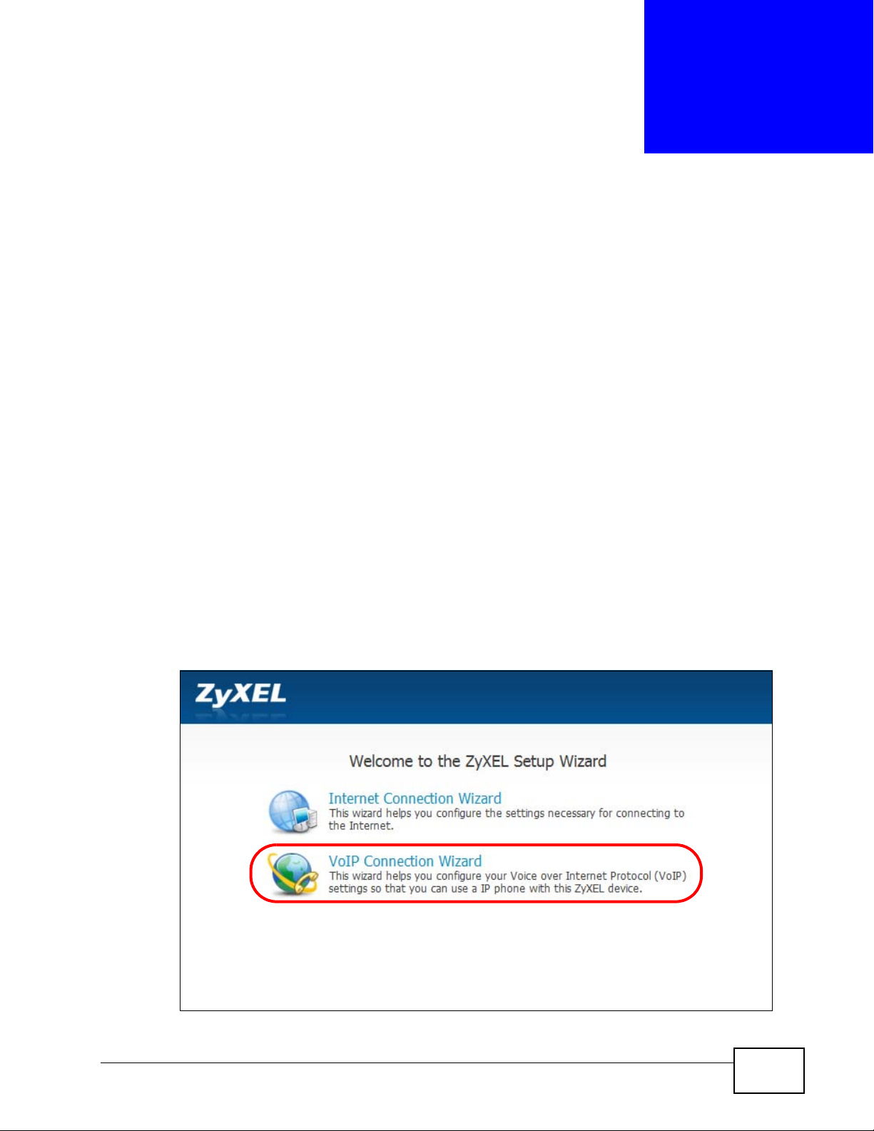
CHAPTER 4
VoIP Connection Wizard
4.1 Overview
This chapter shows you how to use the wizard to set up your voice account(s).
The WiMAX Modem has Voice ov er IP (V oIP) communication capabi lities that allow
you to use a traditional analog telephone to make Internet calls. Y ou can configur e
the WiMAX Modem to use up to two SIP based VoIP accounts.
4.2 Welcome to the ZyXEL Setup Wizard
This is the welcome screen for the ZyXEL Setup Wizard. You can choose to either
configure your Internet connection or your VoIP connection.
The VoIP Connection Wizard screens are described in detail in the following
sections.
Figure 11 Select a Mode
User’s Guide
51
Page 52

Chapter 4 VoIP Connection Wizard
4.2.1 First Voice Account Settings
This VoIP Connection Wizard screen allows you to configure your voice account.
The settings here correspond to the VOICE > Service Configuration > SIP
Setting screen (see Section 10.2 on page 113 for more information).
Figure 12 VoIP Connection > First Voice Account Settings
The following table describes the labels in this screen
Table 8 VoIP Connection > First Voice Account Settings
LABEL DESCRIPTION
SIP Number Enter your SIP number in this field (use the number or text that
comes before the @ symbol in a SIP account like 1234@VoIP-
provider.com). You can use up to 127 ASCII characters.
SIP Server Address Type the IP address or domain name of the SIP server in this
field. It doesn’t matter whether the SIP server is a proxy,
redirect or register server. You can use up to 95 ASCII
characters.
SIP Service Domain Enter the SIP service domain name in this field (the domain
name that comes after the @ symbol in a SIP account like
1234@VoIP-provider.com
Extended set characters.
User Name This is the user name for registering this SIP account with the
SIP register server. Type the user name exactly as it was given
to you. You can use up to 95 ASCII characters.
Password Type the password associated with the user name above. You
can use up to 95 ASCII Extended set characters.
). You can use up to 127 ASCII
52
User’s Guide
Page 53

Chapter 4 VoIP Connection Wizard
Table 8 VoIP Connection > First Voice Account Settings (continued)
LABEL DESCRIPTION
Check here to set up
SIP2 settings.
Back Click to return to the previous screen.
Apply Click to complete the wizard setup and save your configuration.
Exit Click to close the wizard without saving your settings.
After you enter your voice account settings and click Next, the WiMAX Modem
attempts to register your SIP account with the SIP server.
This screen configures SIP account 1. Select the check box if
you h a ve a second SIP a c c ount that y o u want to use. You will
need to configure the same fields for the second SIP account.
Figure 13 VoIP Connection > SIP Registration Test
User’s Guide
This screen displays if SIP account registration fails. Check your WiMAX
connection using the WiMAX Link and Strength Indicator LEDs on the front of
the WiMAX Modem, then wait a few seconds and click Register Again. If your
53
Page 54

Chapter 4 VoIP Connection Wizard
Internet connection was already working, you can click Back and try re-entering
your SIP account settings.
Figure 14 VoIP Connection > SIP Registration Fail
4.2.2 Setup Complete
Click Close to complete and save the VoIP Connection settings.
Figure 15 VoIP Connection > Finish
54
This screen displays if your SIP account registration was successful.
User’s Guide
Page 55

PART II
Basic Screens
The Main Screen (41)
The Setup Screens (57)
55
Page 56

56
Page 57

CHAPTER 5
The Setup Screens
5.1 Overview
Use these screens to configure or view LAN, DHCP Client and WAN settings.
5.1.1 What You Can Do in This Chapter
•The Set IP Address screen (Section 5.2 on page 58) lets you configure the
WiMAX Modem’s IP address and subnet mask.
•The DHCP Client screen (Section 5.3 on page 59) to view connection
information for clients configured by the WiMAX Modem’s internal DHCP server.
•The Time Setting screen (Section 5.4 on page 60) lets you configure your
WiMAX Modem’s time and date keeping settings.
5.1.2 What You Need to Know
The following terms and concepts may help as you read through this chapter.
LAN
A Local Area Network, or a shared communication system to which many
computers are attached. A LAN, as its name implies, is limited to a local area such
as a home or office environment. LANs have different topologies, the most
common being the linear bus and the star configuration.
IP Address
IP addresses identify individual devices on a network. Every networking device
(including computers, servers, routers, printers, etc.) needs an IP address to
communicate across the network. These networking devices are also known as
hosts.
Subnet Mask
The subnet mask specifies the network number portion of an IP address. Your
device will compute the subnet mask automatically based on the IP Address that
User’s Guide
57
Page 58

Chapter 5 The Setup Screens
you entered. Y ou do not need to change the computer subnet mask unless you are
instructed to do so.
Daytime
A network protocol used by devices for debugging and time measurement. A
computer can use this protocol to set its internal clock but only if it knows in which
order the year, month, and day are returned by the server. Not all servers use the
same format.
Time
A network protocol for retrieving the current time from a server. The computer
issuing the command compares the time on its clock to the information returned
by the server, adjusts itself automatically for time zone differences, then
calculates the difference and corrects itself if there has been any temporal drift.
NTP
NTP stands for Network Time Protocol. It is employed by devices connected to the
Internet in order to obtain a precise time setting from an official time server.
These time servers are accurate to within 200 microseconds.
5.1.3 Before You Begin
• Make sure that you have made all the appropriate hardware connections to the
WiMAX Modem, as described in the Quick Start Guide.
• Make sure that you have logg ed in to the web confi gurator at least one time and
changed your password from the de fau lt , as de s cr ib ed in the Quick Start Guide.
5.2 Set IP Address
Click the SETUP icon in the navigation bar to set up the WiMAX Modem’s IP
address and subnet mask. This screen displays this screen by default. If you are in
any other sub-screen you can simply choose Set IP Address from the navigation
menu on the left to open it again.
Figure 16 SETUP > Set IP Address
58
User’s Guide
Page 59

The following table describes the labels in this screen.
Table 9 SETUP > Set IP Address
LABEL DESCRIPTION
IP Address Enter the IP address of the WiMAX Modem on the LAN.
IP Subnet Mask Enter the subnet mask of the LAN.
Apply
Reset Click to restore your previously saved settings.
5.3 DHCP Client
Chapter 5 The Setup Screens
Note: This field is the IP address you use to access the
WiMAX Modem on the LAN. If the web configurator is
running on a computer on the LAN, you lose access to
it as soon as you change this field and click Apply.
You can access the web configurator again by typing
the new IP address in the browser.
Click to save your changes.
Click the SETUP > DHCP Client to view connection information for all clients that
have been configured by the WiMAX Modem’s internal DHCP server.
Figure 17 SETUP > Set IP Address
The following table describes the labels in this screen.
Table 10 SETUP > Set IP Address
LABEL DESCRIPTION
# This indicates the number of the item in this list.
IP Address This indicates the IP address of a connected client device.
Host Name
MAC Address This indicates the MAC address of a connected client device.
This indicates the host name of a connected client device. If the
device is computer, then the host name is the computer name.
User’s Guide
59
Page 60

Chapter 5 The Setup Screens
Table 10 SETUP > Set IP Address (continued)
LABEL DESCRIPTION
Reserve This indicates whether the IP address for the connected client
Apply Click to save your changes.
Refresh Click to refresh the information in the screen.
5.4 Time Setting
Click SETUP > Time Setting to set the date, time, and time zone for the WiMAX
Modem.
device is reserved. When the DHCP server issues IP addresses,
reserved IPs are assigned to specific client devices.
If the IP address is reserved, the client device identified by its
MAC address will always receive this IP address from the DHCP
server.
Figure 18 SETUP > Time Setting
60
The following table describes the labels in this screen.
Table 11 SETUP > Time Setting
LABEL DESCRIPTION
Current Time and Date
Current Time Displays the current time according to the WiMAX Modem.
User’s Guide
Page 61

Chapter 5 The Setup Screens
Table 11 SETUP > Time Setting (continued)
LABEL DESCRIPTION
Current Date Displays the current time according to the WiMAX Modem.
Time and Date Setup
Manual
New Time
New Date Enter the new date in this field, and click Apply.
Get from Time Server
Time Protocol Select the time service protocol that your time server
Time Server
Address
Time Zone Setup
Time Zone Select the time zone at your location.
Daylight Savings Select this if your location uses daylight savings time. Daylight
Start Date Enter which hour on which day of which week of which month
End Date Enter which hour on the which day of which week of which
Apply
Reset
Select this if you want to specify the current date and time in the
fields below.
Enter the new time in this field, and click Apply.
Select this if you want to use a time server to update the current
date and time in the WiMAX Modem.
uses.Check with your ISP or network administrator, or use trialand-error to find a protocol that works.
Daytime (RFC 867) - This format is day/month/year/time
zone.
Time (RFC 868) - This format displays a 4-byte integer giving
the total number of seconds since 1970/1/1 at 0:0:0.
NTP (RFC 1305) - This format is similar to Time (RFC 868).
Enter the IP address or URL of your time server . Check with your
ISP or network administrator if you are unsure of this
information.
savings is a period from late spring to early fall when many
places set their clocks ahead of normal local time by one hour to
give more daytime light in the evening.
daylight-savings time starts.
month daylight-savings time ends.
Click to save your changes.
Click to restore your previously saved settings.
5.4.1 Pre-Defined NTP Time Servers List
The WiMAX Modem uses a pre-defined list of NTP time servers if you do not
specify a time server or it cannot synchronize with the time server you specified.
It can use this list regardless of the time protocol you select.
When the WiMAX Modem uses the list, it randomly selects one server and tries to
synchronize with it. If the synchronization fails, then it goes through the rest of
User’s Guide
61
Page 62

Chapter 5 The Setup Screens
the list in order until either it is successful or all the pre-defined NTP time servers
have been tried.
Table 12 Pre-defined NTP Time Servers
ntp1.cs.wisc.edu
ntp1.gbg.netnod.se
ntp2.cs.wisc.edu
tock.usno.navy.mil
ntp3.cs.wisc.edu
ntp.cs.strath.ac.uk
ntp1.sp.se
time1.stupi.se
tick.stdtime.gov.tw
tock.stdtime.gov.tw
time.stdtime.gov.tw
5.4.2 Resetting the Time
The WiMAX Modem automatically resets the time in the following circumstances:
• When the device starts up, such as when you press the Power button.
• When you click Apply in the SETUP > Time Setting screen.
• Once every 24-hours after starting up.
62
User’s Guide
Page 63

PART III
Advanced Screens
The LAN Configuration Screens (65)
The WAN Configuration Screens (77)
The NAT Configuration Screens (89)
The System Configuration Screens (99)
63
Page 64

64
Page 65

CHAPTER 6
The LAN Configuration Screens
6.1 Overview
Use the ADVANCED > LAN Configuration screens to set up the WiMAX Modem
on the LAN. You can configure its IP address and subnet mask, DHCP services,
and other subnets. You can also control how the WiMAX Modem sends routing
information using RIP.
A Local Area Network (LAN) is a shared communication system to which many
computers are attached. A LAN is usually a computer network limited to the
immediate area, such as the same building or floor of a building.
6.1.1 What You Can Do in This Chapter
•The DHCP Setup screen (Section 6.2 on page 66) lets you enable, disable, and
configure the DHCP server in the WiMAX Modem.
•The Static DHCP screen (Section 6.3 on page 68) lets you assign specific IP
addresses to specific computers on the LAN.
•The IP Static Route screen (Section 6.4 on page 69) lets you examine the
static routes configured in the WiMAX Modem.
•The Other Settings screen (Section 6.5 on page 71) lets you control the
routing information that is sent and received by each subnet assign specific IP
addresses to specific computers on the LAN.
6.1.2 What You Need to Know
The following terms and concepts may help as you read through this chapter.
IP Address
IP addresses identify individual devices on a network. Every networking device
(including computers, servers, routers, printers, etc.) needs an IP address to
communicate across the network. These networking devices are also known as
hosts.
User’s Guide
65
Page 66

Chapter 6 The LAN Configuration Screens
Subnet Masks
Subnet masks determine the maximum number of possible hosts on a network.
You can also use subnet masks to divide one network into multiple sub-networks.
DNS
DNS (Domain Name System) is for mapping a domain name to its corresponding
IP address and vice versa. The DNS server is extremely important because
without it, you must know the IP address of a networking device before you can
access it.
DHCP
A DHCP (Dynamic Host Configuration Protocol) server can assign your WiMAX
Modem an IP address, subnet mask, DNS and other routing information when it’s
turned on.
6.2 DHCP Setup
Click ADVANCED > LAN Configuration > DHCP Setup to enable, disable, and
configure the DHCP server in the WiMAX Modem.
Figure 19 ADVANCED > LAN Configuration > DHCP Setup
66
User’s Guide
Page 67

Chapter 6 The LAN Configuration Screens
The following table describes the labels in this screen.
Table 13 ADVANCED > LAN Configuration > DHCP Setup
LABEL DESCRIPTION
DHCP Setup
Enable DHCP
Server
IP Pool Starting
Address
Pool Size Enter the number of IP addresses to allocate. This number must be at
DNS Server
First, Second
and Third DNS
Server
Select this if you want the WiMAX Modem to be the DHCP server on the
LAN. As a DHCP server, the WiMAX Modem assigns IP addresses to
DHCP clients on the LAN and provides the subnet mask and DNS server
information.
Enter the IP address from which the WiMAX Modem begins allocating IP
addresses, if you have not specified an IP address for this computer in
ADVANCED > LAN Configuration > Static DHCP.
least one and is limited by a subnet mask of 255.255.255.0 (regardless
of the subnet the WiMAX Modem is in). For example, if the IP Pool
Start Address is 10.10.10.10, the WiMAX Modem can allocate up to
10.10.10.254, or 245 IP addresses.
Specify the IP addresses of a maximum of three DNS servers that the
network can use. The WiMAX Modem provides these IP addresses to
DHCP clients. You can specify these IP addresses two ways.
From ISP - provide the DNS servers provided by the ISP on the WAN
port.
User Defined - enter a static IP address.
DNS Relay - this setting will relay DNS information from the DNS
server obtained by the WiMAX Modem.
None - no DNS service will be provided by the WiMAX Modem.
Apply
Reset Click to restore your previously saved settings.
Click to save your changes.
User’s Guide
67
Page 68

Chapter 6 The LAN Configuration Screens
6.3 Static DHCP
Click ADVANCED > LAN Configuration > Static DHCP to assign specific IP
addresses to specific computers on the LAN.
Note: This screen has no effect if the DHCP server is not enabled. You can enable it
in ADVANCED > LAN Configuration > DHCP Setup.
Figure 20 ADVANCED > LAN Configuration > Static DHCP
The following table describes the labels in this screen.
Table 14 ADVANCED > LAN Configuration > Static DHCP
LABEL DESCRIPTION
# The number of the item in this list.
MAC Address
IP Address Enter the IP address you want the WiMAX Modem to assign to the
Apply Click to save your changes.
Reset Click to restore your previously saved settings.
Enter the MAC address of the computer to which you want the WiMAX
Modem to assign the same IP address.
computer.
68
User’s Guide
Page 69

6.4 IP Static Route
Click ADVANCED > LAN Configuration > IP Static Route to look at the static
routes configured in the WiMAX Modem.
Note: The first static route is the default route and cannot be modified or deleted.
Figure 21 Advanced> LAN Configuration > IP Static Route
Chapter 6 The LAN Configuration Screens
The following table describes the icons in this screen.
Table 15 Advanced> LAN Configuration > IP Static Route
ICON DESCRIPTION
Edit
Click to edit this item.
Delete
Click to delete this item.
The following table describes the labels in this screen.
Table 16 Advanced> LAN Configuration > IP Static Route
LABEL DESCRIPTION
# The number of the item in this list.
Name
Active
Destination
Gateway This field displays the IP address of the gateway to which the WiMAX
Apply
Reset
This field displays the name that describes the static route.
This field shows whether this static route is active (Yes) or not (No).
This field displays the destination IP address(es) that this static route
affects.
Modem should send packets for the specified Destination. The
gateway is a router or a switch on the same network segment as the
device's LAN or WAN port. The gateway helps forward packets to their
destinations.
Click to save your changes.
Click to restore your previously saved settings.
User’s Guide
69
Page 70
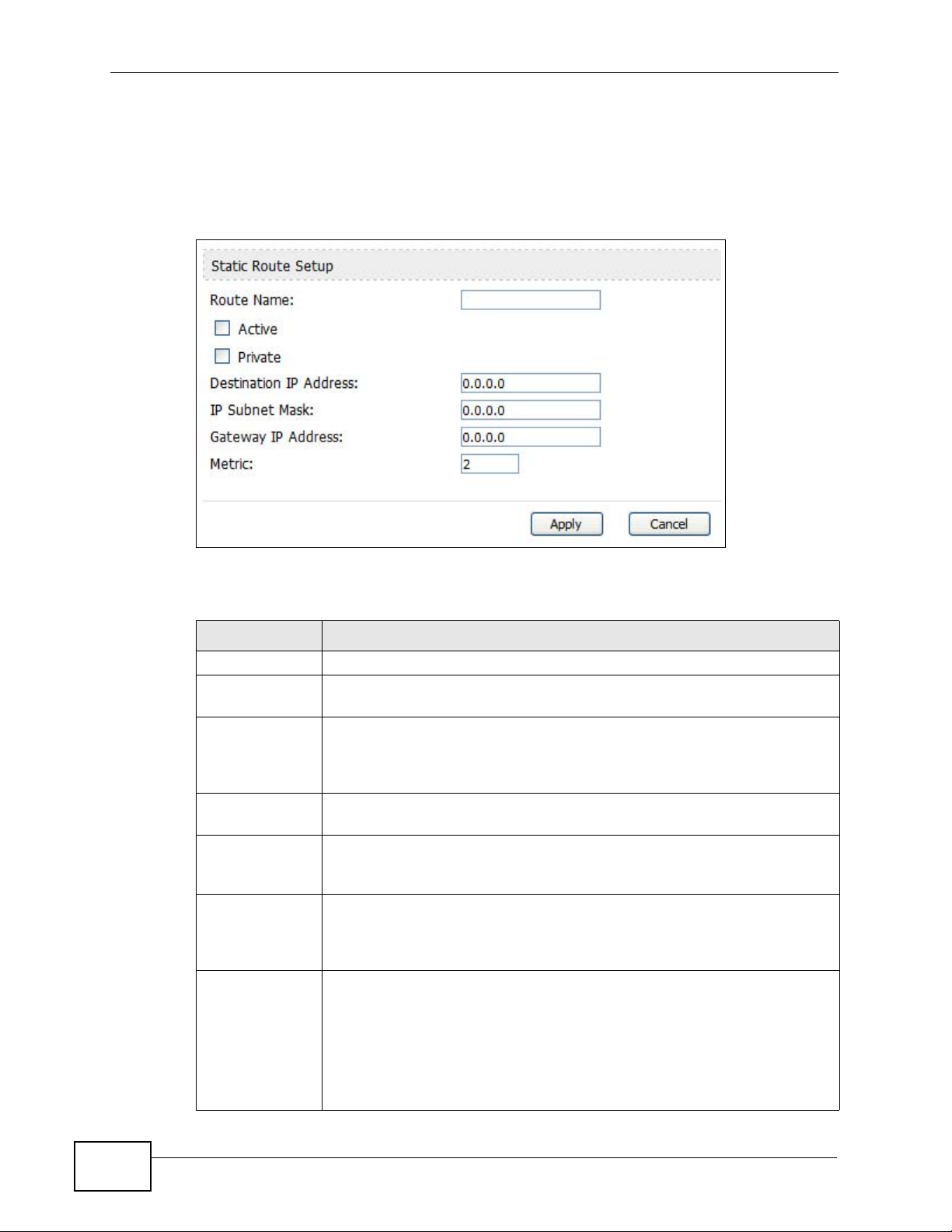
Chapter 6 The LAN Configuration Screens
6.4.1 IP Static Route Setup
Click an Edit icon in ADVANCED > LAN Configuration > IP Static Route to
edit a static route in the WiMAX Modem.
Figure 22 Advanced> LAN Configuration > IP Static Route Setup
The following table describes the labels in this screen.
Table 17 Management > Static Route > IP Static Route > Edit
LABEL DESCRIPTION
Route Name Enter the name of the static route.
Active Select this if you want the static route to be used. Clear this if you do
not want the static route to be used.
Private Select this if you do not want the WiMAX Modem to tell other routers
about this static route. For example, you might select this if the static
route is in your LAN. Clear this if you want the WiMAX Modem to tell
other routers about this static route.
Destination IP
Address
IP Subnet Mask
Gateway IP
Address
Metric
Enter one of the destination IP addresses that this static route affects.
Enter the subnet mask that defines the range of destination IP
addresses that this static route affects. If this static route affects only
one IP address, enter 255.255.255.255.
Enter the IP address of the gateway to which the WiMAX Modem should
send packets for the specified Destination. The gateway is a router or
a switch on the same network segment as the device's LAN or WAN
port. The gateway helps forward packets to their destinations.
Usually, you should keep the default value. This field is related to RIP.
The metric represents the "cost of transmission". A router determines
the best route for transmission by choosing a path with the lowest
"cost". The smaller the metric, the lower the "cost". RIP uses hop count
as the measurement of cost, where 1 is for a directly-connected
network. The metric must be 1-15; if you use a value higher than 15,
the routers assume the link is down.
70
User’s Guide
Page 71

Table 17 Management > Static Route > IP Static Route > Edit (continued)
LABEL DESCRIPTION
Apply Click to save your changes.
Cancel Click to return to the previous screen without saving your changes.
6.5 Other Settings
Click ADVANCED > LAN Configuration > Other Settings to set the RIP and
Multicast options.
Figure 23 ADVANCED > LAN Configuration > Advanced
Chapter 6 The LAN Configuration Screens
The following table describes the labels in this screen.
Table 18 ADVANCED > LAN Configuration > Other Settings
LABEL DESCRIPTION
RIP & Multicast Setup
RIP Direction Use this field to control how much routing information the WiMAX
Modem sends and receives on the subnet.
• None - The WiMAX Modem does not send or receive routing
information on the subnet.
• Both - The WiMAX Modem sends and receives routing information
on the subnet.
• In Only - The WiMAX Modem only receives routing information on
the subnet.
• Out Only - The WiMAX Modem only sends routing information on
the subnet.
RIP Version
Select which version of RIP the WiMAX Modem uses when it sends or
receives information on the subnet.
• RIP-1 - The WiMAX Modem uses RIPv1 to exchange routing
information.
• RIP-2B - The WiMAX Modem broadcasts RIPv2 to exchange routing
information.
• RIP-2M - The WiMAX Modem multicasts RIPv2 to exchange routing
information.
User’s Guide
71
Page 72

Chapter 6 The LAN Configuration Screens
Table 18 ADVANCED > LAN Configuration > Other Settings (continued)
LABEL DESCRIPTION
Multicast You do not have to enable multicasting to use RIP-2M. (See RIP
Version.)
Select which version of IGMP the WiMAX Modem uses to support
multicasting on the LAN. Multicasting sends packets to some computers
on the LAN and is an alternative to unicasting (sending packets to one
computer) and broadcasting (sending packets to every computer).
• None - The WiMAX Modem does not support multicasting.
• IGMP-v1 - The WiMAX Modem supports IGMP version 1.
• IGMP-v2 - The WiMAX Modem supports IGMP version 2.
Multicasting can improve overall network performance. However, it
requires extra processing and generates more network traffic. In
addition, other computers on the LAN have to support the same version
of IGMP.
Apply
Reset
Click to save your changes.
Click to restore your previously saved settings.
6.6 Technical Reference
The following section contains additional technical information about the WiMAX
Modem features described in this chapter.
6.6.1 IP Address and Subnet Mask
Similar to the way houses on a street share a common street name, computers on
a LAN share one common network number.
Where you obtain your network number depends on your particular situation. If
the ISP or your network administrator assigns you a block of registered IP
addresses, follow their instructions in selecting the IP addresses and the subnet
mask.
If the ISP did not explicitly give you an IP network number, then most likely you
have a single user account and the ISP will assign you a dynamic IP address when
the connection is established. If this is the case, it is recommended that you select
a network number from 192.168.0.0 to 192.168.255.0 and you must enable the
Network Address Translation (NAT) feature of the WiMAX Modem. The Internet
Assigned Number Authority (IANA) reserved this block of addresses sp ecifically for
private use; please do not use any other number unless you are told otherwise.
Let's say you select 192.168.1.0 as the network number; which covers 254
individual addresses, from 192.168.1.1 to 192.168.1.254 (zero and 255 are
reserved). In other words, the first three numbers specify the network number
while the last number identifies an individual computer on that network.
72
User’s Guide
Page 73

Once you have decided on the network number , pick an IP address that is easy to
remember, for instance, 192.168.1.1, for your WiMAX Modem, but make sure that
no other device on your network is using that IP address.
The subnet mask specifies the network number portion of an IP address. Your
WiMAX Modem will compute the subnet mask automatically based on the IP
address that you entered. You don't need to change the subnet mask computed
by the WiMAX Modem unless you are instructed to do otherwise.
6.6.2 DHCP Setup
DHCP (Dynamic Host Configuration Protocol, RFC 2131 and RFC 2132) allows
individual clients to obtain TCP/IP configuration at start-up from a server. You can
configure the WiMAX Modem as a DHCP server or disable it. When configured as a
server, the WiMAX Modem provides the TCP/IP configuration for the clients. If
DHCP service is disabled, you must have another DHCP server on your LAN, or
else each computer must be manually configured.
Chapter 6 The LAN Configuration Screens
The WiMAX Modem is pre-configured with a pool of IP addresses for the DHCP
clients (DHCP Pool). See the product specif ic a t i o ns in the appendices. Do not
assign static IP addresses from the DHCP pool to your LAN computers.
These parameters should work for the majority of installations. If your ISP gives
you explicit DNS server address(es), see Section 6.3 on page 68.
6.6.3 LAN TCP/IP
The WiMAX Modem has built-in DHCP server capability that assigns IP addresses
and DNS servers to systems that support DHCP client capability.
The LAN parameters of the WiMAX Modem are preset in the factory with the
following values:
• IP address of 192.168.1.1 with subnet mask of 255.255.255.0 (24 bits)
• DHCP server enabled with 32 client IP addresses starting from 192.168.1.33.
These parameters should work for the majority of installations. If your ISP gives
you explicit DNS server address(es), see Section 6.3 on page 68.
User’s Guide
73
Page 74

Chapter 6 The LAN Configuration Screens
6.6.4 DNS Server Address
DNS (Domain Name System) is for mapping a domain name to its corresponding
IP address and vice versa. The DNS server is extremely important because
without it, you must know the IP address of a machine before you can access it.
The DNS server addresses that you enter in the DHCP setup are passed to the
client machines along with the assigned IP address and subnet mask.
There are two ways that an ISP disseminates the DNS server addresses. The first
is for an ISP to tell a customer the DNS server addresses, usually in the form of an
information sheet, when s/he signs up. If your ISP gives you the DNS server
addresses, enter them in the DNS Server fields in DHCP Setup, otherwise, leave
them blank.
Some ISPs choose to pass the DNS servers using the DNS server extensions of
PPP IPCP (IP Control Protocol) after the connection is up. If your ISP did not give
you explicit DNS servers, chances are the DNS serv ers are conv eyed through IPCP
negotiation. The WiMAX Modem supports the IPCP DNS server extensions through
the DNS proxy feature.
If the Primary and Secondary DNS Server fields in the LAN Setup screen are
not specified, for instance, left as 0.0.0.0, the WiMAX Modem tells the DHCP
clients that it itself is the DNS server. When a computer sends a DNS query to the
WiMAX Modem, the WiMAX Modem forwards the query to the real DNS server
learned through IPCP and relays the response back to the computer.
Please note that DNS proxy works only when the ISP uses the IPCP DNS server
extensions. It does not mean you can leave the DNS servers out of the DHCP
setup under all circumstances. If your ISP gives you explicit DNS servers, make
sure that you enter their IP addresses in the LAN Setup screen. This way, the
WiMAX Modem can pass the DNS servers to the computers and the computers can
query the DNS server directly without the WiMAX Modem’s intervention.
6.6.5 RIP Setup
RIP (Routing Information Protocol) allows a router to exchange routing
information with other routers. The RIP Direction field controls the sending and
receiving of RIP packets. When set to:
• Both - the WiMAX Modem will broadcast its routing table periodically and
incorporate the RIP information that it receives.
74
• In Only - the WiMAX Modem will not send any RIP packets but will accept all
RIP packets received.
• Out Only - the WiMAX Modem will send out RIP packets but will not accept any
RIP packets received.
User’s Guide
Page 75

• None - the WiMAX Modem will not send any RIP packets and will ignore any RIP
packets received.
The Version field controls the format and the broadcasting method of the RIP
packets that the WiMAX Modem sends (it recog nizes both formats when
receiving). RIP-1 is universally supported; but RIP-2 carries more information.
RIP-1 is probably adequate for most networks, unless you have an unusual
network topology.
Both RIP-2B and RIP-2M sends the routing data in RIP-2 format; the difference
being that RIP-2B uses subnet broadcasting while RIP-2M uses multicasting.
6.6.6 Multicast
Traditionally, IP packets are transmitted in one of either two ways - Unicast (1
sender - 1 recipient) or Broadcast (1 sender - everybody on the network).
Multicast delivers IP packets to a group of hosts on the network - not everybody
and not just 1.
Chapter 6 The LAN Configuration Screens
IGMP (Internet Group Multicast Protocol) is a network-layer protocol used to
establish membership in a Multicast group - it is not used to carry user data. IGMP
version 2 (RFC 2236) is an improvement over version 1 (RFC 1112) but IGMP
version 1 is still in wide use. If you would like to read more detailed information
about interoperability between IGMP version 2 and version 1, please see sections
4 and 5 of RFC 2236. The class D IP address is used to identify host groups and
can be in the range 224.0.0.0 to 239.255.255.255. The address 224.0.0.0 is not
assigned to any group and is used by IP multicast computers. The address
224.0.0.1 is used for query messages and is assigned to the permanent group of
all IP hosts (including gateways). All host s must join t he 224.0.0.1 group in order
to participate in IGMP. The address 224.0.0.2 is assigned to the multicast routers
group.
The WiMAX Modem supports both IGMP version 1 (IGMP-v1) and IGMP version 2
(IGMP-v2). At start up, the WiMAX Modem queries all directly connected
networks to gather group membership. After that, the WiMAX Modem periodically
updates this information. IP multicasting can be enabled/disabled on the WiMAX
Modem LAN and/or WAN interfaces in the web configurator (LAN; WAN). Select
None to disable IP multicasting on these interfaces.
User’s Guide
75
Page 76

Chapter 6 The LAN Configuration Screens
76
User’s Guide
Page 77

CHAPTER 7
The WAN Configuration Screens
7.1 Overview
Use the ADVANCED > WAN Configuration screens to set up your WiMAX
Modem’s Wide Area Network (WAN) or Internet features.
A Wide Area Network (or WAN) links geographically dispersed locations to other
networks or the Internet. A WAN configuration can include switched and
permanent telephone circuits, terrestrial radio systems and satellite systems.
7.1.1 What You Can Do in This Chapter
•The Internet Connection screen (Section 7. 2 on page 80) lets yo u set up your
WiMAX Modem’s Internet settings.
•The WiMAX Configuration screen (Section 7.3 on page 82) lets set up the
frequencies used by your WiMAX Modem.
•The Antenna Selection screen (Section 7.4 on page 86) to switch between the
WiMAX Modem’s internal antenna and the external antennas (MAX -216M1R plus
only; other models do not support this option.)
•The Advanced screen (Section 7.5 on page 87) lets configure your DNS server,
RIP, Multicast and Windows Networking settings.
7.1.2 What You Need to Know
The following terms and concepts may help as you read through this chapter.
WiMAX
WiMAX (Worldwide Interoperability for Microwave Access) is the IEEE 802.16
wireless networking standard, which provides high-bandwidth, wide-range
wireless service across wireless Metropolitan Area Networks (MANs). ZyXEL is a
member of the WiMAX Forum, the industry group dedicated to promoting and
certifying interoperability of wireless broadband products.
In a wireless MAN, a wireless-equipped computer is known either as a mobile
station (MS) or a subscriber station (SS). Mobile stations use the IEEE 802.16e
standard and are able to maintain connectivity while switching their connection
User’s Guide
77
Page 78

Chapter 7 The WAN Configuration Screens
from one base station to another base station (handover) while subscriber
stations use other standards that do not have this capability (IEEE 802.16-2004,
for example). The following figure shows an MS-equipped notebook computer
MS1 moving from base station BS1’s coverage area and connecting to BS2.
Figure 24 WiMax: Mobile Station
WiMAX technology uses radio signals (around 2 to 10 GHz) to connect subscriber
stations and mobile stations to local base stations. Numerous subscriber stations
and mobile stations connect to the network through a singl e base station ( BS), as
in the following figure.
Figure 25 WiMAX: Multiple Mobile Stations
A base station's coverage area can extend over many hundreds of meters, even
under poor conditions. A base station provides network access to subscriber
stations and mobile stations, and communicates with other base stations.
The radio frequency and bandwidth of the link between t he WiMAX Modem and the
base station are controlled by the base station. The WiMAX Modem follows the
base station’s configur ation.
78
User’s Guide
Page 79

Chapter 7 The WAN Configuration Screens
Authentication
When authenticating a user, the base station uses a third-party RADIUS or
Diameter server known as an AAA (Authentication, Authorizat ion and Ac counting)
server to authenticate the mobile or subscriber stations.
The following figure shows a base station using an AAA server to authenticate
mobile station MS, allowing it to access the Internet.
Figure 26 Using an AAA Server
In this figure, the dashed arrow shows the PKM (Privacy Key Management)
secured connection between the mobile station and the base station, and the solid
arrow shows the EAP secured connection between the mobile station, the base
station and the AAA server. See the WiMAX security appendix for more details.
User’s Guide
79
Page 80

Chapter 7 The WAN Configuration Screens
7.2 Internet Connection
Click ADVANCED > WAN Configuration to set up your WiMAX Modem’s Internet
settings.
Note: Not all WiMAX Modem models have all the fields shown here.
Figure 27 ADVANCED > WAN Configuration > Internet Connection
The following table describes the labels in this screen.
Table 19 ADVANCED > WAN Configuration > Internet Connection > ISP
Parameters for Internet Access
LABEL DESCRIPTION
ISP Parameters for Internet Access
User Name Use this field to enter the username associated with your Internet
access account. You can enter up to 61 printable ASCII characters.
Password Use this field to enter the password associated with your Internet
access account. You can enter up to 47 printable ASCII characters.
Anonymous
Identity
Enter the anonymous identity provided by your Internet Service
Provider. Anonymous identity (also known as outer identity) is used
with EAP-TT LS encryption. The anonymous identity is used to route
your authentication request to the correct authentication server,
and does not reveal your real user name. Your real user name and
password are encrypted in the TLS tunnel, and only the anonymous
identity can be seen.
Leave this field blank if your ISP did not give you an anonymous
identity to use.
80
User’s Guide
Page 81

Chapter 7 The WAN Configuration Screens
Table 19 ADVANCED > WAN Configuration > Internet Connection > ISP
Parameters for Internet Access (continued)
LABEL DESCRIPTION
PKM This field displays the Privacy Key Management version number.
PKM provides security between the WiMAX Modem and the base
station. At the time of writing, the WiMAX Modem supports PKMv2
only. See the WiMAX security appendix for more information.
Authentication This field displays the user authentication method. Authentication is
the process of confirming the identity of a mobile station (by means
of a username and password, for example).
Check with your service provider if you are unsure of the correct
setting for your account.
Choose from the following user authentication methods:
• TTLS (Tunnelled Transport Layer Security)
• TLS (Transport Layer Security)
Note: Not all WiMAX Modems support TLS authentication.
Check with your service provider for details.
TTLS Inner EAP This field displays the type of secondary authentication method.
Once a secure EAP-TTLS connection is established, the inner EAP is
the protocol used to exchange security information between the
mobile station, the base station and the AAA server to authenticate
the mobile station. See the WiMAX security appendix for more
details.
This field is available only when TTLS is selected in the
Authentication field.
The WiMAX Modem supports the following inner authentication
types:
• CHAP (Challenge Handshake Authentication Protocol)
• MSCHAP (Microsoft CHAP)
• MSCHAPV2 (Microsoft CHAP version 2)
• PAP (Password Authentication Protocol)
Auth Mode Select the authentication mode from the drop-down list box.
This field is not ava i l a ble in al l W i MA X Mo d e ms . Ch e c k wit h y o u r
service provider for details.
The WiMAX Modem supports the following authentication modes:
•User Only
• Device Only with Cert
• Certs and User Authentication
Certificate This is the security certificate the WiMAX Modem uses to
authenticate the AAA server. Use the TOOLS > > Trusted CAs
screen to import certificates to the WiMAX Modem.
WAN IP Address Assignment
User’s Guide
81
Page 82

Chapter 7 The WAN Configuration Screens
Table 19 ADVANCED > WAN Configuration > Internet Connection > ISP
Parameters for Internet Access (continued)
LABEL DESCRIPTION
Get
automatically
from ISP
(Default)
Use Fixed IP
Address
IP Subnet Mask Enter a subnet mask in dotted decimal notation.
Gateway IP
Address
Apply Click to save your changes.
Reset Click to restore your previously saved settings.
Select this if you have a dynamic IP address. A dynamic IP address
is not fixed; the ISP assigns you a different one each time you
connect to the Internet.
A static IP address is a fixed IP that your ISP gives you. Type your
ISP assigned IP address in the IP Address field below.
Refer to the appendices to calculate a subnet mask If you are
implementing subnetting.
Specify a gateway IP address (supplied by your ISP).
7.3 WiMAX Configuration
Click ADVANCED > WAN Configuration > WiMAX Configuration to set up the
frequencies used by your WiMAX Modem.
In a WiMAX network, a mobile or subscriber station must use a radio frequency
supported by the base station to communicate. When the WiMAX Modem looks for
a connection to a base station, it can search a range of frequencies .
82
User’s Guide
Page 83

Chapter 7 The WAN Configuration Screens
Radio frequency is measured in Hertz (Hz).
Table 20 Radio Frequency Conversion
1 kHz = 1000 Hz
1 MHz = 1000 kHz (1000000 Hz)
1 GHz = 1000 MHz (1000000 kHz)
Figure 28 ADVANCED > WAN Configuration >WiMAX Configuration
User’s Guide
The following table describes the labels in this screen.
Table 21 ADVANCED > WAN Configuration >WiMAX Configuration
LABEL DESCRIPTION
DL Frequency /
Bandwidth
These fields show the downlink frequency settings in kilohertz (kHz).
Enter values in these fields to have the WiMAX Modem scan these
frequencies for available channels in ascending numerical order.
Note: The Bandwidth field is not user-configurable; when the
WiMAX Modem finds a WiMAX connection, its frequency
is displayed in this field.
Contact your service provider for details of supported frequencies.
Apply Click to save your changes.
Reset Click to restore your previously saved settings.
83
Page 84
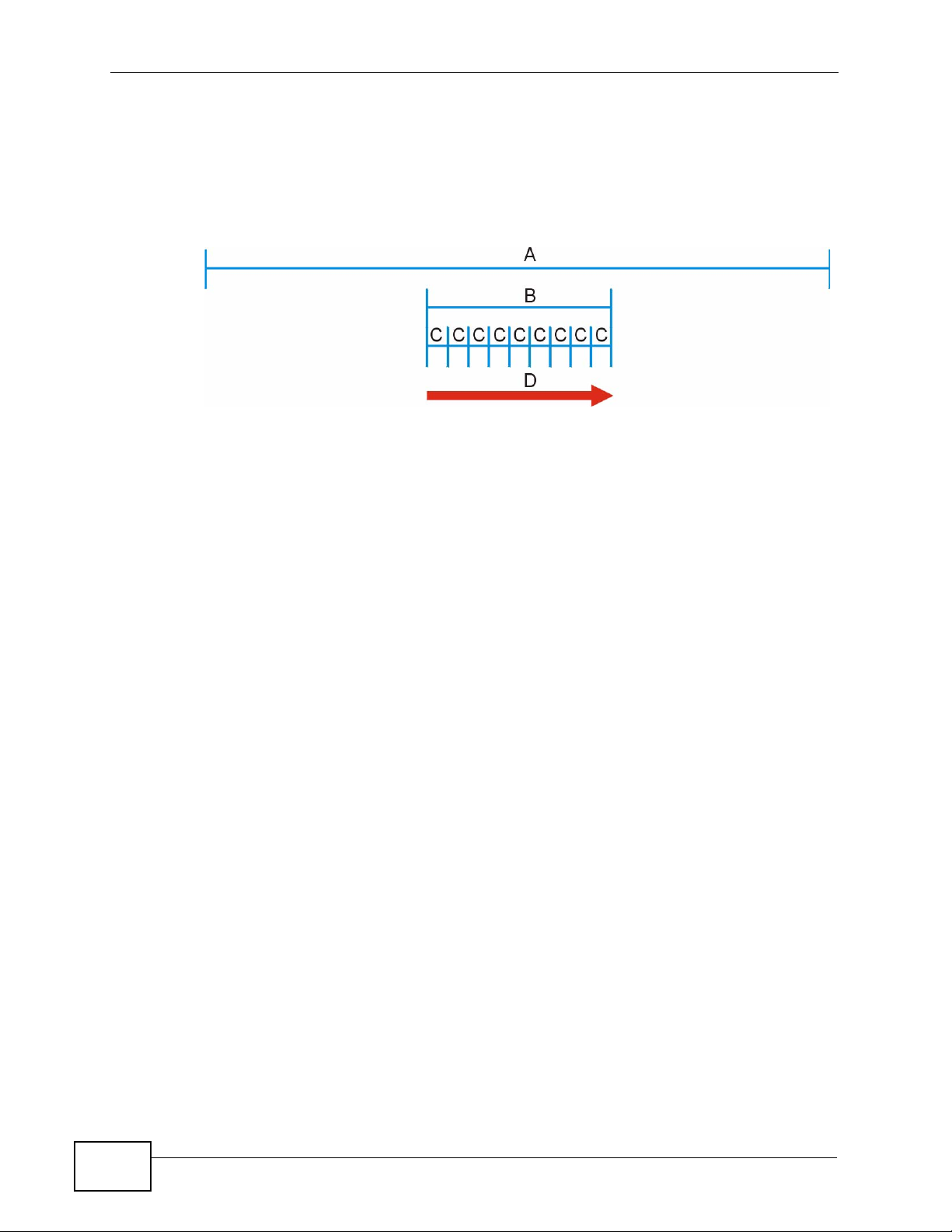
Chapter 7 The WAN Configuration Screens
7.3.1 Frequency Ranges
The following figure shows the WiMAX Modem searching a range of frequencies to
find a connection to a base station.
Figure 29 Frequency Ranges
In this figure, A is the WiMAX frequency range. “WiMAX frequency r ange” refers to
the entire range of frequencies the WiMAX Modem is ca pable of using to transmit
and receive (see the Product Specifications appendix for details).
In the figure, B shows the operator frequency range. This is the range of
frequencies within the WiMAX frequency range supported by your operator
(service provider).
The operator range is subdivided into bandwidth steps. In the figure, each C is a
bandwidth step.
The arrow D shows the WiMAX Modem searching for a connection.
Have the WiMAX Modem search only certain frequencies by configuring the
downlink frequencies. Your operator can give you information on the supported
frequencies.
The downlink frequencies are points of the frequency range your WiMAX Modem
searches for an available connection. Use the Site Survey screen to set these
bands. You can set the downlink frequencies anywhere within the WiMAX
frequency range. In this example, the downlink frequencies have been set to
search all of the operator range for a connection.
7.3.2 Configuring Frequency Settings
84
You need to set the WiMAX Modem to scan one or more specific radio frequencies
to find an available connection to a WiMAX base station.
Use the WiMAX Frequency screen to define the radio frequencies to be searched
for available wireless connections. See Section 7.3.3 on page 85 for an example of
using the WiMAX Frequency screen.
User’s Guide
Page 85

Chapter 7 The WAN Configuration Screens
Note: It may take several minutes for the WiMAX Modem to find a connection.
• The WiMAX Modem searches the DL Frequency settings in ascending numerical
order, from [1] to [9].
Note: The Bandwidth field is no t user-configurable; when the WiMAX Modem finds a
WiMAX connection, its frequency is displayed in this field.
• If you enter a 0 in a DL Frequency field, the WiMAX Modem immediately
moves on to the next DL Frequency field.
• When the WiMAX Modem connects to a base station, the values in this screen
are automatically set to the base station’s frequency. The next time the WiMAX
Modem searches for a connection, it searches only this frequency. If you want
the WiMAX Modem to search other frequencies , e nt er th em in the DL
Frequency fields.
The following table describes some examples of DL Frequency settings.
Table 22 DL Frequency Example Settings
EXAMPLE 1 EXAMPLE 2
Bandwidth: 2500000 2500000
DL Frequency
[1]:
DL Frequency [2] 0 2600000
DL Frequency
[3]:
DL Frequency
[4]:
2550000 2550000
00
00
The WiMAX Modem
searches at 2500000
kHz, and then searches
at 2550000 kHz if it has
not found a connection.
The WiMAX Modem
searches at 2500000 kHz
and then at 2550000 kHz if
it has not found an
available connection. If it
still does not find an
available connection, it
searches at 2600000 kHz.
7.3.3 Using the WiMAX Frequency Screen
In this example, your Internet service provider has given you a list of supported
frequencies: 2.51, 2.525, 2.6, and 2.625.
1 In the DL Frequency [1] field, enter 2510000 (2510000 kilohertz (kHz) is equal
to 2.51 gigahertz).
2 In the DL Frequency [2] field, enter 2525000.
3 In the DL Frequency [3] field, enter 2600000.
User’s Guide
85
Page 86

Chapter 7 The WAN Configuration Screens
4 In the DL Frequency [4] field, enter 2625000.
Leave the rest of the DL Frequency fields at zero. The screen appears as follows.
Figure 30 Completing the WiMAX Frequency Screen
5 Click Apply. The WiMAX Modem stores your settings.
When the WiMAX Modem searches for available frequencies, it scans all
frequencies from DL Frequency [1] to DL Frequency [4]. When it finds an
available connection, the fields in this screen will be automatically set to use that
frequency.
7.4 Antenna Selection
Click ADVANCED > WAN Configuration > Antenna Selection to switch
between the WiMAX Modem’s internal antenna and the (optinoal) external
antennas, if they are installed.
Note: This screen only pertains to the MAX-216M1R plus. Other devices in this series
do not support external antennas.
Figure 31 ADVANCED > WAN Configuration > Antenna Selection
The following table describes the labels in this screen.
Table 23 ADVANCED > WAN Configuration > Advanced
LABEL DESCRIPTION
Select the Antenna Switch Mode
Use Internal
Antenna
Use External
Antenna
Select this to use the device’s internal antenna.
Select this to use the device’s external antenna. If you select this
option but do not have external antennas attached, you may
experience poor reception.
86
External antennas are optional and not required.
User’s Guide
Page 87

Table 23 ADVANCED > WAN Configuration > Advanced (continued)
LABEL DESCRIPTION
Apply Click to save your changes.
Reset Click to restore your previously saved settings.
7.5 Advanced
Click ADVANCED > WAN Configuration > Advanced to configure your DNS
server, RIP, Multicast and Windows Networking settings.
Figure 32 ADVANCED > WAN Configuration > Advanced
Chapter 7 The WAN Configuration Screens
User’s Guide
87
Page 88

Chapter 7 The WAN Configuration Screens
The following table describes the labels in this screen.
Table 24 ADVANCED > WAN Configuration > Advanced
LABEL DESCRIPTION
DNS Servers
First, Second and
Third DNS Server
RIP & Multicast Setup
RIP Direction Select the RIP direction from None, Both, In Only and Out Only.
RIP Version Select the RIP version from RIP-1, RIP-2B and RIP-2M.
Multicast IGMP (Internet Group Multicast Protocol) is a network-layer
Windows Networking (NetBIOS over TCP/IP)
Allow between LAN
and WAN
Select Obtained from ISP if your ISP dynamically assigns DNS
server information (and the WiMAX Modem's WAN IP address). Use
the drop-down list box to select a DNS server IP address that the
ISP assigns in the field to the right.
Select UserDefined if you have the IP address of a DNS server.
Enter the DNS server's IP address in the field to the right. If you
chose UserDefined, but leave the IP address set to 0.0.0.0,
UserDefined changes to None after you click Apply. If you set a
second choice to UserDefined, and enter the same IP address, the
second UserDefined changes to None after you click Apply.
Select None if you do not want to configure DNS servers. You must
have another DHCP server on your LAN, or else the computers
must have their DNS server addresses manually configured. If you
do not configure a DNS server, you must know the IP address of a
computer in order to access it.
protocol used to establish membership in a multicast group. The
WiMAX Modem supports both IGMP version 1 (IGMP-v1) and
IGMP-v2. Select None to disable it.
Select this check box to forward NetBIOS packets from the LAN to
the WAN and from the WAN to the LAN. If your firewall is enabled
with the default policy set to block WAN to LAN traffic, you also
need to enable the default WAN to LAN firewall rule that forwards
NetBIOS traffic.
88
Clear this check box to block all NetBIOS packets going from the
LAN to the WAN and from the WAN to the LAN.
Allow Trigger Dial Select this option to allow NetBIOS packets to initiate calls.
Apply Click to save your changes.
Reset Click to restore your previously saved settings.
User’s Guide
Page 89

CHAPTER 8
The NAT Configuration Screens
8.1 Overview
Use these screens to configure port forwarding and trigger ports for the WiMAX
Modem. You can also enable and disable SIP, FTP, and H.323 ALG.
Network Address Translation (NAT) maps a host’s IP address within one network
to a different IP address in another network. For example, you can use a NAT
router to map one IP address from your ISP to multiple private IP addresses for
the devices in your home network.
8.1.1 What You Can Do in This Chapter
•The General screen (Section 8.2 on page 89) lets you enable or disable NAT
and to allocate memory for NAT and firewall rules.
•The Port Forwarding screen (Section 8.3 on page 90) lets you look at the
current port-forwarding rules in the WiMAX Modem, and to enable, disable,
activate, and deactivate each one.
•The Trigger Port screen (Section 8.4 on page 94) lets you maintain trigger port
forwarding rules for the WiMAX Modem.
•The ALG screen (Section 8.5 on page 96) lets you enable and disable SIP
(VoIP), FTP (file transfer), and H.323 (audio-visual) ALG in the WiMAX Modem.
8.2 General
Click ADVANCED > NA T Configuration > General to enable or d isable NAT and
to allocate memory for NAT and firewall rules.
Figure 33 ADVANCED > NAT Configuration > General
User’s Guide
89
Page 90

Chapter 8 The NAT Configuration Screens
The following table describes the labels in this screen.
Table 25 ADVANCED > NAT Configuration > General
LABEL DESCRIPTION
Enable Network
Address Translation
Max NAT/Firewall
Session Per User
Apply Click to save your changes.
Cancel Click to return to the previous screen without saving your
Select this if you want to use port forwarding, trigger ports, or any
of the ALG.
When computers use peer to peer applications, such as file
sharing applications, they may use a large number of NAT
sessions.
client can establish, this can result in all of the available NAT
sessions being used. In this case, no additional NAT sessions can
be established, and users may not be able to access the Internet.
Each NAT session establishes a corresponding firew all session. Use
this field to limit the number of NAT/firewall sessions each client
computer can establish through the WiMAX Modem.
If your network has a small number of clients using peer to peer
applications, you can raise this number to ensure that their
performance is not degraded by the number of NAT sessions they
can establish. If your network has a large number of users using
peer to peer applications, you can lower this number to ensure no
single client is using all of the available NAT sessions.
changes.
If you do not limit the number of NAT sessions a single
8.3 Port Forwarding
A NAT server set is a list of inside (behind NAT on the LAN) servers, for example,
web or FTP, that you can make accessible to the outside world even though NAT
makes your whole inside network appear as a single machine to the outside world.
Use the ADVANCED > NAT Configuration > Port Forwarding screen to
forward incoming service requests to the server(s) on your local network. You
may enter a single port number or a range of port numbers to be forwarded, and
the local IP address of the desired server. The port number identifies a service; for
example, web service is on port 80 and FTP on port 21. In some cases, such as for
unknown services or where one server can support more than one service (for
example both FTP and web service), it might be better to specify a range of port
numbers.
In addition to the servers for specified services, NAT supports a default server. A
service request that does not have a server explicitly designated for it is
forwarded to the default server. If the default is not defined, the service request is
simply discarded.
90
User’s Guide
Page 91

For example, let's say you want to assign ports 21-25 to one FTP, Telnet and
SMTP server (A in the example), port 80 to another (B in the example) and assign
a default server IP address of 192.168.1.35 to a third (C in the example). You
assign the LAN IP addresses and the ISP assigns the WAN IP address. The NAT
network appears as a single host on the Internet.
Figure 34 Multiple Servers Behind NAT Example
8.3.1 Port Forwarding Options
Chapter 8 The NAT Configuration Screens
Click ADVANCED > NAT Configuration > Port Forwarding to look at the
current port-forwarding rules in the WiMAX Modem, and to enable, disable,
activate, and deactivate each one. You can also set up a default server to handle
ports not covered by rules.
Figure 35 ADVANCED > NAT Configuration > Port Forwarding
User’s Guide
91
Page 92

Chapter 8 The NAT Configuration Screens
The following table describes the icons in this screen.
Table 26 Advanced> VPN Transport > Customer Interface
ICON DESCRIPTION
Edit
Click to edit this item.
Delete
Click to delete this item.
The following table describes the labels in this screen.
Table 27 ADVANCED > NAT Configuration > Port Forwarding
LABEL DESCRIPTION
Default Server Setup
Default Server Enter the IP address of the server to which the WiMAX Modem should
forward packets for ports that are not specified in the Port Forwarding
section below or in the TOOLS > Remote MGMT screens. Enter
0.0.0.0 if you want the WiMAX Modem to discard these packets instead.
Port Forwarding
# The number of the item in this list.
Active Select this to enable this rule. Clear this to disable this rule.
Name
Start Port This field displays the beginning of the range of port numbers
End Port This field displays the end of the range of port numbers forwarded by
Server IP
Address
Action Click the Edit icon to set up a port forwarding rule or alter the
This field displays the name of the rule. It does not have to be unique.
forwarded by this rule.
this rule. If it is the same as the Start Port, only one port number is
forwarded.
This field displays the IP address of the server to which packet for the
selected port(s) are forwarded.
configuration of an existing port forwarding rule.
92
Apply
Reset
Click the Delete icon to remove an existing port forwarding rule.
Click to save your changes.
Click to restore your previously saved settings.
User’s Guide
Page 93

8.3.2 Port Forwarding Rule Setup
Click a port forwarding rule’s Edit icon in the ADVANCED > NAT Configuration
> Port Forwarding screen to activate, deactivate, or edit it.
Figure 36 ADVANCED > NAT Configuration > Port Forwarding > Rule Setup
The following table describes the labels in this screen.
Chapter 8 The NAT Configuration Screens
Table 28 ADVANCED > NAT Configuration > Port Forwarding > Rule Setup
LABEL DESCRIPTION
Active Select this to enable this rule. Clear this to disable this rule.
Service Name
Start Port
End Port
Server IP
Address
Apply Click to save your changes.
Cancel Click to return to the previous screen without saving your changes.
Enter a name to identify this rule. You can use 1 - 31 printable ASCII
characters, or you can leave this field blank. It does not have to be a
unique name.
Enter the port number or range of port numbers you want to forward to
the specified server.
To forward one port number, enter the port number in the Start Port
and End Port fields.
To forward a range of ports,
• enter the port number at the beginning of the range in the Start
Port field
• enter the port number at the end of the range in the End Port field.
Enter the IP address of the server to which to forward packets for the
selected port number(s). This server is usually on the LAN.
User’s Guide
93
Page 94

Chapter 8 The NAT Configuration Screens
8.4 Trigger Port
Some services use a dedicated range of ports on the client side and a dedicated
range of ports on the server side. With regular port forwarding you set a
forwarding port in NAT to forward a service (coming in from the server on the
WAN) to the IP address of a computer on the client side (LAN). The problem is
that port forwarding only forwards a service to a single LAN IP address. In order to
use the same service on a different LAN computer, you have to manually replace
the LAN computer's IP address in the forwarding port with another LAN
computer's IP address,
Tr i g ger port forwarding solves this problem by allowing c o m p ut ers o n the LAN to
dynamically take turns using the service. The WiMAX Modem records the IP
address of a LAN computer that sends traffic to the WAN to request a service with
a specific port number and protocol (a "trigger" port). When the WiMAX Modem's
WAN port receives a response with a specific port number and protocol
("incoming" port), the WiMAX Modem forwards the traffic to the LAN IP address of
the computer that sent the request. After that computer’s connection for that
service closes, another computer on the LAN can use the service in the same
manner. This way you do not need to configure a new IP address each time you
want a different LAN computer to use the application.
Click ADVANCED > NAT Configuration > Trigger Port to maintain trigger port
forwarding rules for the WiMAX Modem.
Figure 37 ADVANCED > NAT Configuration > Trigger Port
The following table describes the labels in this screen.
Table 29 ADVANCED > NAT Configuration > Trigger Port
LABEL DESCRIPTION
# The number of the item in this list.
Name
Incoming
Enter a name to identify this rule. You can use 1 - 15 printable ASCII
characters, or you can leave this field blank. It does not have to be a
unique name.
94
User’s Guide
Page 95

Chapter 8 The NAT Configuration Screens
Table 29 ADVANCED > NAT Configuration > Trigger Port (continued)
LABEL DESCRIPTION
Start Port
End Port
Trigger
Start Port
End Port
Enter the incoming port number or range of port numbers you want to
forward to the IP address the WiMAX Modem records.
To forward one port number, enter the port number in the Start Port
and End Port fields.
To forward a range of ports,
• enter the port number at the beginning of the range in the Start
Port field
• enter the port number at the end of the range in the End Port field.
If you want to delete this rule, enter zero in the Start Port and End
Port fields.
Enter the outgoing port number or range of port numbers that makes
the WiMAX Modem record the source IP address and assign it to the
selected incoming port number(s).
T o select one port number, enter the port number in the Start Port and
End Port fields.
To select a range of ports,
• enter the port number at the beginning of the range in the Start
Port field
• enter the port number at the end of the range in the End Port field.
If you want to delete this rule, enter zero in the Start Port and End
Port fields.
Apply
Cancel Click to return to the previous screen without saving your changes.
Click to save your changes.
8.4.1 Trigger Port Forwarding Example
The following is an example of trigger port forwarding. In this example, J is Jane’ s
computer and S is the Real Audio server.
Figure 38 Trigger Port Forwarding Example
User’s Guide
95
Page 96

Chapter 8 The NAT Configuration Screens
1 Jane requests a file from the Real Audio server (port 7070).
2 Port 7070 is a “trigger” port and causes the WiMAX Modem to record Jane’s
computer IP address. The WiMAX Modem associates Jane's computer IP address
with the "incoming" port range of 6970-7170.
3 The Real Audio server responds using a p ort number ranging between 6970-7170.
4 The WiMAX Modem forwards the traffic to Jane’s computer IP address.
5 Only Jane can connect to the Real Audio server until the connection is closed or
times out. The WiMAX Modem times out in three minutes with UDP (User
Datagram Protocol), or two hours with TCP/IP (Transfer Control Protocol/Internet
Protocol).
Two points to remember about trigger ports:
1 Trigger events only happen on data that is coming from inside the WiMAX Modem
and going to the outside.
2 If an application needs a continuous data stream, that port (range) will be tied up
so that another computer on the LAN can’t trigger it.
8.5 ALG
Some applications, such as SIP, cannot operate through NAT (are NAT unfriendly) because they embed IP addresses and port numbers in their packets’
data payload.
Some NAT routers may include a SIP Application Layer Gateway (ALG). An
Application Layer Gateway (ALG) manages a specific protocol (such as SIP, H.323
or FTP) at the application layer.
A SIP ALG allows SIP calls to pass through NAT by examining and translating IP
addresses embedded in the data stream.
96
User’s Guide
Page 97
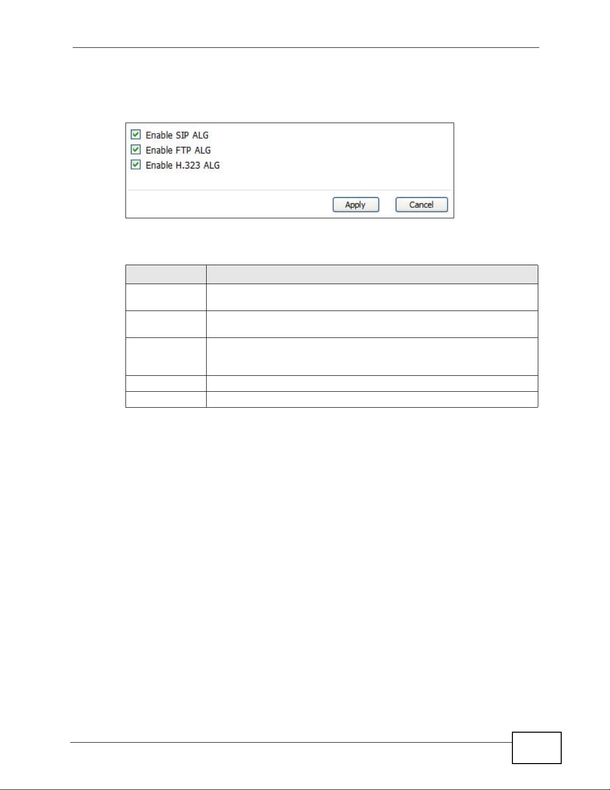
Chapter 8 The NAT Configuration Screens
Click ADVANCED > NAT Configuration > ALG to enable and disable SIP (V oIP),
FTP (file transfer), and H.323 (audio-visual) ALG in the WiMAX Modem.
Figure 39 ADVANCED > NAT Configuration > ALG
The following table describes the labels in this screen.
Table 30 ADVANCED > NAT Configuration > ALG
LABEL DESCRIPTION
Enable SIP ALG Select this to make sure SIP (VoIP) works correctly with port-
forwarding and port-triggering rules.
Enable FTP ALG Select this to make sure FTP (file transfer) works correctly with port-
forwarding and port-triggering rules.
Enable H.323
ALG
Apply Click to save your changes.
Cancel Click to return to the previous screen without saving your changes.
Select this to make sure H.323 (audio-visual programs, such as
NetMeeting) works correctly with port-forwarding and port-triggering
rules.
User’s Guide
97
Page 98

Chapter 8 The NAT Configuration Screens
98
User’s Guide
Page 99

CHAPTER 9
The System Configuration
Screens
9.1 Overview
Click ADVANCED > System Configuration to set up general system settings,
change the system mode, change the password, configure the DDNS server
settings, and set the current date and time.
9.1.1 What You Can Do in This Chapter
•The General screen (Section 9.2 on page 101) lets you change the WiMAX
Modem’s mode, set up its system name , domain name, idle timeout, and
administrator password.
•The Dynamic DNS screen (Section 9.3 on page 102) lets you set up the WiMAX
Modem as a dynamic DNS client.
•The Firmware screen (Section 9.4 on page 104) lets you upload new firmware
to the WiMAX Modem.
•The Configuration screen (Section 9.5 on page 106) lets you back up or
restore the configuration of the WiMAX Modem.
•The Restart screen (Section 9.6 on page 107) lets you restart your WiMAX
Modem from within the web configurator.
9.1.2 What You Need to Know
The following terms and concepts may help as you read through this chapter.
System Name
The System Name is often used for identification purposes. Because some ISPs
check this name you should enter your computer's "Computer Name".
• In Windows 2000: Click Start > Settings > Control Panel and then doubleclick the System icon. Select the Network Identification tab and then click
the Properties button. Note the entry for the Computer Name field and enter
it as the System Name.
User’s Guide
99
Page 100

Chapter 9 The System Configuration Screens
• In Windows XP: Click Start > My Computer > View system information and
then click the Computer Name tab. Note the entry in the Full computer
name field and enter it as the WiMAX Modem System Name.
Domain Name
The Domain Name entry is what is propagated to the DHCP clients on the LAN. If
you leave this blank, the domain name obtained by DHCP from the ISP is used.
While you must enter the host name (System Name) on each individual computer,
the domain name can be assigned from the WiMAX Modem via DHCP.
DNS Server Address Assignment
Use DNS (Domain Name System) to map a domain name to its corresponding IP
address and vice versa, for instance, the IP address of www.zyxel.com is
204.217.0.2. The DNS server is extremely important because without it, you must
know the IP address of a computer before you can access it.
The WiMAX Modem can get the DNS server addresses in the following ways:
1 The ISP tells you the DNS server addresses, usually in the form of an information
sheet, when you sign up. If your ISP g i ves you DNS server addresses, enter them
in the DNS Server fields in the SYSTEM General screen.
2 If the ISP did not give you DNS server information, leave the DNS Server fields in
the SYSTEM General screen set to 0.0.0.0 for the ISP to dynamically assign the
DNS server IP addresses.
100
User’s Guide
 Loading...