

Page 1
Default Login Details
User’s Guide
LTE7461-M602
LTE Outdoor
AN I P Addres s htt p ://192.168.1.1
L
Login admin
Password See the Zyxel Device label
Router
ersion 2.00 Ed 1, 1/2019
V
Copyright © 2019 Zyxel Communications Corporation
Page 2

IMPORTANT!
READ CAREFULLY BEFORE USE.
KEEP THIS GUIDE FOR FUTURE REFERENCE.
This is a User’s Guide for the LTE7461-M602. Screenshots and graphics in this book may differ slightly from
what you see due to differences in your product firmware or your computer operating system. Every
effort has been made to ensure that the information in this manual is accurate.
Related Documentation
• Quick Start Guide
The Quick Start Guide shows how to connect the Zyxel Device.
• More Information
Go to support.zyxel.com to find other information on the Zyxel Device
.
LTE7461-M602 User’s Guide
2
Page 3

Document Conventions
Warnings and Notes
These are how warnings and notes are shown in this guide.
Warnings tell you about things that could harm you or your Zyxel
Device.
Note: Notes tell you other important information (for example, other things you may need to
configure or helpful tips) or recommendations.
Syntax Conventions
• The LTE7461-M602 in this user’s guide may be referred to as the “Zyxel Device” in this guide.
• Product labels, screen names, field labels and field choices are all in bold font.
• A right angle bracket ( > ) within a screen name denotes a mouse click. For example, Network Setting
> Routing > DNS Route means you first click Network Setting in the navigation panel, then the Routing
sub menu and finally the DNS Route tab to get to that screen.
Icons Used in Figures
Figures in this user guide may use the following generic icons. The Zyxel Device icon is not an exact
representation of your Zyxel Device.
xel Device
Zy
Serve
r
nter
Pri
neric Router
Ge
Fire
wall
itch
Sw
US
B Storage Device
LTE7461-M602 User’s Guide
3
Page 4

Contents Overview
Contents Overview
ser’s Guide ......................................................................................................................................12
U
In
troduction ...................................................... ..................................................................................... 13
The Web Configurator ......................................................................................................................... 16
Quick Start ............................................................................................................................................. 23
echnical Reference ........................................................................................................................25
T
C
onnection Status Screens ................................................................................................................. 26
Broadband ................................................................................... ......................................................... 33
Wireless ................................................................................................................................................... 42
Home Networking .......................................................... .............. .............. .............. ............................. 65
Routing .............................................................. ........................................................ ............................. 87
Network Address Translation (NAT) ..................................................................................................... 95
Dynamic DNS Setup ........................................................................................................................... 105
Firewall ................................................................................................................................................. 109
MAC Filter ............................................................................................................................................ 119
Certificates .......................................................................................................................................... 121
Log ..................................................................... .............. .............. .............. ......................................... 130
Traffic Status ........................................................................................................................................ 133
ARP Table ............................................................................................................................................ 136
Routing Table ...................................................................................................................................... 138
Cellular WAN Status ............................................................................................................................ 141
System ................................................. ................................................................................................. 146
User Account ...................................................................................................................................... 147
Remote Management ....................................................................................................................... 150
TR-069 Client ........................................................................................................................................ 155
Time Settings ........................................................................................................................................ 158
Email Notification ................................................................................................................................ 161
Log Setting ........................................................................................................................................... 164
Firmware Upgrade .............................................................................................................................. 167
Backup/Restore .................................................................................................................................. 169
Diagnostic ........................................................................................................................................... 172
Troubleshooting .................................................................................................................................. 174
Ap
pendices .....................................................................................................................................178
LTE7461-M602 User’s Guide
4
Page 5

Table of Contents
Table of Contents
cument Conventions......................................................................................................................3
Do
Contents Overview..............................................................................................................................4
Table of Contents................... .................................... ................................... .......................................5
Part I: User’s Guide..........................................................................................12
Cha
pter 1
Introduction........................................................................................................................................13
verview ......................................................................................................................................... 13
1.1 O
1.2 Application for the Zyxel Device ................................................................................................... 13
1.3 Managing the Zyxel Device........................................................................................................... 13
1.4 Good Habits for Managing the Zyxel Device ............................................................................. 14
1.5 LEDs (Lights) ..................................................................................................................................... 14
1.6 The RESET Button ............................................................................................................................. 15
Chapter 2
The Web Configurator............................. ................................... ........................................................16
2.1 Overview ......................................................................................................................................... 16
2.1.1 Accessing the Web Configurator ........................................................................................ 16
2.2 Web Configurator Layout .............................................................................................................. 18
2.2.1 Settings Icon .......................................................................................................................... 18
2.2.2 Widget Icon ................................................................................ .............. .............. ............... 22
pter 3
Cha
Quick Start..........................................................................................................................................23
3.1 O
verview ......................................................................................................................................... 23
3.2 Quick Start Setup ............................................................................................................................ 23
3.3 Time Zone ........................................................................................................................................ 23
3.4 WiFi Setup ......................................................................................................................................... 24
3.5 Quick Start Setup-Finish .................................................................................................................. 24
Par
t II: Technical Reference ...........................................................................25
pter 4
Cha
Connection Status Screens....................................... .................................................... ....................26
LTE7461-M602 User’s Guide
5
Page 6

Table of Contents
he Connection Status Screen ...................................................................................................... 26
4.1 T
4.1.1 The Connectivity Screen ...................................................................................................... 26
4.1.2 The System Info Screen ......................................................................................................... 27
4.1.3 The WiFi Settings Screen ....................................................................................................... 29
4.1.4 The LAN Screen ..................................................................................................................... 31
Cha
pter 5
Broadband..........................................................................................................................................33
5.1 O
verview ......................................................................................................................................... 33
5.1.1 What You Can Do in this Chapter ....................................................................................... 33
5.1.2 What You Need to Know ..................................................................................................... 33
5.1.3 Before You Begin ................................................................................................................... 34
5.2 Cellular WAN Screen ...................................................................................................................... 34
5.3 SIM Configuration Screen .............................................................................................................. 36
5.4 The Band Configuration Screen .................................................................................................... 37
5.5 PLMN Configuration Screen........................................................................................................... 38
5.6 IP Passthrough Screen .................................................................................................................... 40
pter 6
Cha
Wireless...............................................................................................................................................42
verview .......................................................................................................................................... 42
6.1 O
6.1.1 What You Can Do in this Chapter ....................................................................................... 42
6.1.2 What You Need to Know ..................................................................................................... 42
6.2 The General Screen ....................................................................................................................... 43
6.2.1 No Security ............ .............. .............. .............. .............. .............. .............. ............................. 44
6.2.2 More Secure (WPA2-PSK)...................................................................................................... 45
6.3 MAC Authentication ...................................................................................................................... 46
6.4 The WPS Screen ............................................................................................................................... 48
6.5 The WMM Screen ............................................................................................................................ 49
6.6 The Others Screen .......................................................................................................................... 50
6.7 Technical Reference ...................................................................................................................... 52
6.7.1 WiFi Network Overview ......................................................................................................... 53
6.7.2 Additional Wireless Terms ..................................................................................................... 54
6.7.3 WiFi Security Overview .......................................................................................................... 54
6.7.4 Signal Problems ................................ .............. .............. .............. .............. .............. ............... 56
6.7.5 BSS..................................................................... .............. .............. .............. ............................. 57
6.7.6 Preamble Type ................................. .............. .............. .............. .............. .............. ............... 57
6.7.7 WiFi Protected Setup (WPS) ................................................................................................. 58
Chapter 7
Home Networking..............................................................................................................................65
7.1 O
verview .......................................................................................................................................... 65
7.1.1 What You Can Do in this Chapter ....................................................................................... 65
LTE7461-M602 User’s Guide
6
Page 7

Table of Contents
What You Need To Know ..................................................................................................... 65
7.1.2
7.2 The LAN Setup Screen .................................................................................................................... 66
7.3 The Static DHCP Screen ................................................................................................................. 70
7.3.1 Before You Begin ................................................................................................................... 70
7.4 The UPnP Screen ............................................................................................................................. 72
7.5 Technical Reference ...................................................................................................................... 73
7.6 Turning on UPnP in Windows 7 Example .......................................................................................74
7.6.1 Auto-discover Your UPnP-enabled Network Device ........................................................ 75
7.7 Turning on UPnP in Windows 10 Example ..................................................................................... 77
7.7.1 Auto-discover Your UPnP-enabled Network Device ........................................................ 79
7.8 Web Configurator Easy Access in Windows 7 ............................................................................. 82
7.9 Web Configurator Easy Access in Windows 10 ........................................................................... 84
Cha
pter 8
Routing................................................................................................................................................87
verview .......................................................................................................................................... 87
8.1 O
8.2 Configuring Static Route ................................................................................................................ 87
8.2.1 Add/Edit Static Route ........................................................................................................... 88
8.3 The DNS Route Screen .................................................................................................................... 90
8.3.1 Add/Edit DNS Route .............................................................................................................. 90
8.4 The Policy Route Screen ................................................................................................................. 91
8.4.1 Add/Edit Policy Route ........................................................................................................... 92
8.5 RIP...................................................................................................................................................... 93
8.5.1 The RIP Screen ...... ................................................................................................................. 93
Chapter 9
Network Address Translation (NAT)........................................................ .................................... ......9 5
verview .......................................................................................................................................... 95
9.1 O
9.1.1 What You Can Do in this Chapter ....................................................................................... 95
9.1.2 What You Need To Know ..................................................................................................... 95
9.2 The Port Forwarding Screen ........................................................................................................... 96
9.2.1 The Port Forwarding Screen ................................................................................................. 97
9.2.2 Add/Edit Port Forwarding ..................................................................................................... 98
9.3 The Port Triggering Screen .................................................... ......................................................... 99
9.3.1 Add/Edit Port Triggering Rule ............................................................................................. 101
9.4 The DMZ Screen ............................................................................................................................ 102
9.5 The ALG Screen ............................................................................................................................ 103
Cha
pter 10
Dynamic DNS Setup.........................................................................................................................105
10.1 DN
S Overview ............................................................................................................................. 105
10.1.1 What You Can Do in this Chapter ................................................................................... 105
10.1.2 What You Need To Know ................................................................................................. 105
LTE7461-M602 User’s Guide
7
Page 8

Table of Contents
The DNS Entry Screen ................................................................................................................ 106
10.2
10.2.1 Add/Edit DNS Entry ............................................................................................................ 106
10.3 The Dynamic DNS Screen .......................................................................................................... 107
pter 11
Cha
Firewall..............................................................................................................................................109
11.1 Overview ...................................................................................................................................... 109
11.1.1 What You Need to Know About Firewall ........................................................................ 109
11.2 The Firewall Screen...................................................................................................................... 110
11.2.1 What You Can Do in this Chapter ................................................................................... 110
11.3 The Firewall General Screen ...................................................................................................... 110
11.4 The Protocol (Customized Services) Screen ............................................................................ 111
11.4.1 Add Customized Service .................................................................................................. 112
11.5 The Access Control (Rules) Screen ........................................................................................... 113
11.5.1 Access Control Add New ACL Rule Screen ................................................................... 114
11.6 DoS Screen .................................................................................................................................. 115
11.7 Firewall Technical Reference .................................................................................................... 116
11.7.1 Firewall Rules Overview .................................................................................................... 116
11.7.2 Guidelines For Enhancing Security With Your Firewall .................................................. 117
11.7.3 Security Considerations .................................................................................................... 118
Chapter 12
MAC Filter .........................................................................................................................................119
Cha
12.1 M
12.2 The MAC Filter Screen ................................................................................................................ 119
pter 13
AC Filter Overview ................................................................................................................... 119
Certificates .......................................................................................................................................121
13.1 O
13.2 Local Certificates ........................................................................................................................ 121
13.3 Trusted CA.................................................................................................................................... 125
13.4 Import Trusted CA Certificate .................................................................................................... 126
13.5 View Trusted CA Certificate....................................................................................................... 126
13.6 Certificates Technical Reference ............................................................................................. 127
verview ..................................................................................................................................... 121
13.1.1 What You Can Do in this Chapter ................................................................................... 121
13.2.1 Create Certificate Request .............................................................................................. 122
13.2.2 View Certificate Request .................................................................................................. 123
13.6.1 Verifying a Certificate ....................................................................................................... 128
Chapter 14
Log ....................................................................................................................................................130
14.1 L
og Overview............................................................................................................................... 130
14.1.1 What You Can Do in this Chapter ................................................................................... 130
LTE7461-M602 User’s Guide
8
Page 9

Table of Contents
What You Need To Know ................................................................................................. 130
14.1.2
14.2 The System Log Screen .............................................................................................................. 131
14.3 The Security Log Screen ............................................................................................................. 131
pter 15
Cha
Traffic Status ...................... ................................... .................................... ........................................133
15.1 Traffic Status Overview ............................................................................................................... 133
15.1.1 What You Can Do in this Chapter ................................................................................... 133
15.2 The WAN Status Screen .............................................................................................................. 133
15.3 The LAN Status Screen ................................................................................................................ 134
pter 16
Cha
ARP Table..........................................................................................................................................136
16.1 A
RP Table Overview ................................................................................................................... 136
16.1.1 How ARP Works .................................................................................................................. 136
16.2 ARP Table Screen ........................................................................................................................ 137
Cha
pter 17
Routing Table....................................................................................................................................138
17.1 Routing Table Overview ............................................................................................................. 138
17.2 The Routing Table Screen .......................................................................................................... 138
pter 18
Cha
Cellular WAN Status ........................................................................................................................141
18.1 Cellular WAN Status Overview................................................................................................... 141
18.2 The Cellular WAN Status Screen ............................................................................................... 141
Cha
pter 19
System...............................................................................................................................................146
19.1 System Overview ........................................................................................................................ 146
19.2 The System Screen ...................................................................................................................... 146
Chapter 20
User Account............ .................................... .................................... ............................... .................147
20.1 User Account Overview ............................................................................................................. 147
20.2 The User Account Screen ........................................................................................................... 147
20.2.1 The User Account Add/Edit Screen ................................................................................. 148
Cha
pter 21
Remote Management.....................................................................................................................150
21.1 O
21.2 The MGMT Services Screen ........................................................................................................ 150
21.3 The MGMT Services for IP Passthrough Screen ........................................................................ 151
verview ...................................................................................................................................... 150
LTE7461-M602 User’s Guide
9
Page 10

Table of Contents
he Trust Domain Screen ............................................................................................................ 152
21.4 T
21.5 The Add Trust Domain Screen ................................................................................................... 153
Chapter 22
TR-069 Client................... .................................................... .................................... ..........................155
Cha
22.1 O
22.2 The TR-069 Client Screen ............................................................................................................ 155
pter 23
verview ...................................................................................................................................... 155
Time Settings........................ .................................... .................................................... .....................158
23.1 T
ime Settings Overview............................................................................................................... 158
23.2 The Time Screen .......................................................................................................................... 158
Cha
pter 24
Email Notification.................................................... .................................... .....................................161
mail Notification Overview ...................................................................................................... 161
24.1 E
24.2 The Email Notification Screen ................................................................................................... 161
24.2.1 Email Notification Edit ....................................................................................................... 162
pter 25
Cha
Log Setting........................................................................................................................................164
25.1 L
og Setting Overview .......................................................... ....................................................... 164
25.2 The Log Setting Screen .............................................................................................................. 164
Cha
pter 26
Firmware Upgrade.............. .................................... .................................... .....................................167
Cha
26.1 O
26.2 The Firmware Upgrade Screen ................................................................................................. 167
pter 27
verview ..................................................................................................................................... 167
Backup/Restore...............................................................................................................................169
Cha
27.1 Backu
27.2 The Backup/Restore Screen ...................................................................................................... 169
27.3 The Reboot Screen ..................................................................................................................... 170
pter 28
p/Restore Overview ........................................................................................................ 169
Diagnostic.........................................................................................................................................172
tic Overview .................................................................................................................. 172
Cha
28.1 Diagnos
28.2 The Ping/TraceRoute/Nslookup Test Screen ............................................................................ 172
pter 29
Troubleshooting................................................................................................................................174
29.1 O
verview ..................................................................................................................................... 174
LTE7461-M602 User’s Guide
10
Page 11

Table of Contents
ower and Hardware Connections ......................................................................................... 174
29.2 P
29.3 Zyxel Device Access and Login ................................................................................................ 174
29.4 Internet Access ........................................................................................................................... 176
29.5 UPnP ............................................................................................................................................. 177
t III: Appendices......................................................................................178
Par
A
ppendix A Customer Support ..................................................................................................... 179
Appendix B IPv6............................................................................................................................... 185
Appendix C Legal Information ...................................................................................................... 192
Index.................................................................................................................................................200
LTE7461-M602 User’s Guide
11
Page 12

PART I
User’s Guide
12
Page 13

1.1 Overview
The Zyxel Device is an outdoor LTE (Long Term Evolution) router that supports (but not limited to) the
following:
• Gigabit Ethernet connection
• DHCP (Dynamic Host Configuration Protocol) server
• NAT (Network Address Translation)
• DMZ (Demilitarized Zone)
•Port Forwarding/Triggering
• ALG (Application Layer Gateway)
• Bridge/Router mode
• Dynamic DNS (Domain Name System) for the first APN (Access Point Name)
• Static/Dynami c Route setting for RIP (Routing Information Protocol)
• Remote Management under Bridge mode
• Address Resolution Protocol (ARP)
• Firewall that uses Stateful Packet Inspection (SPI) technology
• Protects against Denial of Service (DoS) attacks
• Filter of LAN MAC address, LAN IP address and URLs
• Local and remote device management
• Firmware upgrade via TR-069 and Web Configu rator
C
HAPTER
1
Introduction
The embedded Web-based Configurator enables straightforward management and maintenance. Just
insert the SIM card (with an active data plan) and make the hardware connections. See the Quick Start
Guide for how to do the hardware installation, wall mounting, Internet setup and turning on/off WiFi
(optional).
1.2 Application for the Zyxel Device
Wireless WAN
The LTE Device can co nnec t to th e Int ernet through a 2 G /3G / 4 G LTE SIM card to a c ces s a wireless WA N
connection. Just insert a SIM card into the SIM card slot at the bottom of the Zyxel Device.
te: You must insert the SIM card into the card slot before turning on the Zyxel Device.
No
LTE7461-M602 User’s Guide
13
Page 14

Chapter 1 Introduction
L
TE (4G)/3G/2G
WiFi
Internet Access
Your Zyxel Device provides shared Internet access by connecting to an LTE network. A computer can
connect to the Zyxel Device’s PoE injector for configuration via the Web Configurator.
Figure 1 Zyxel Device’s Internet Access Application
1.3 Managing the Zyxel Device
Use the Web Configurator for management of the Zyxel Device using a (supported) web browser.
1.4 Good Habits for Managing the Zyxel Device
Do the following things regularly to make the Zyxel Device more secure and to manage the Zyxel
Device more effectively.
• Change the password. Use a password that’s not easy to guess and th a t c on s is ts o f di f ferent types of
characters, such as numbers and letters.
• Write down the password and put it in a safe place.
• Back up the configuration (and make sure you know how to restore it). Refer to Section 23.2 on p a ge
147. Restoring an earlier working configuration may be useful if the Zyxel Device becomes unstable or
even crashes. If you forget your password to access the Web Configurator, you will have to reset the
Zyxel Device to its factory default settings. If you backed up an earlier configuration file, you would
not have to totally re-configure the Zyxel Device. You could simply restore your last configuration.
1.5 Front and Rear Panels
The LED indicators are located on the front panel. The wall mounting panel is located on the rear.
LTE7461-M602 User’s Guide
14
Page 15

Figure 2 Front and Rear Panels
Chapter 1 Introduction
1.6 LEDs (Lights)
None of the LEDs are on if the Zyxel Device is not receiving power.
Table 1 LTE7461-M602 LED Descriptions
COLOR STATUS DESCRIPTION
Red
Amber
Gree
O
Blinking
Slow
On
Of
f
On
n
B
linking
(slow)
B
linking
(fast)
f
Of
The Zyxel Device is abnormal status.
The Zyxel Device is booting.
The WiFi network is activated.
The WiFi network is not activat ed.
The Zyxel Device is registered and successfully connected to a mobile network.
The Zyxel Device is not connected to Mobile network.
The Zyxel Device is trying to connect to a 4G/3G network.
There is no service.
n
Note: Blinking (slow) means the LED blinks once per second.
Blinking (fast) means the LED blinks once per 0.2 second.
LTE7461-M602 User’s Guide
15
Page 16

1.7 The RESET Button
If you forget your password or cannot access the Web Configurator, you will need to use the
button of the Zyxel Device as shown in the following figure to reload the factory-default configuration
file. This means that you will lose all configurations
reset to
1234
and the IP address will be reset to
Chapter 1 Introduction
that you had previously saved, the password will be
192.168.1.1
RESET
.
Figure 3
1
Make sure the Zyxel Device is connected to power and
To set the Zyxel Device back to the factory default settings, press the
2
Reset Button and IO ports
LED is on.
RESET button for 5 seconds.
No
te: If you press the
cause the system to reboot.
RESET
button for more than 2 seconds but less than 5 seconds, it will
LTE7461-M602 User’s Guide
16
Page 17

2.1 Overview
The Web Configurator is an HTML-based management interface that allows easy Zyxel Device setu p
and management via Internet browser. Use Internet Explorer 8.0 and later versions or Mozilla Firefox 3
and later versions or Safari 2.0 and later versions. The recommended screen resolution is 1024 by 768
pixels.
In order to use the Web Configurator you need to allow:
• Web browser pop-up windows from your Zyxel Device. Web pop-up blocking is enabled by default in
Windows 10.
• JavaScript (enabled by default).
• Java permissions (enabled by default).
C
HAPTER
2
The Web Configurator
2.1.1
Accessing the Web Configurator
1 Make sure your Zyxel Device hardware is properly connected (refer to the Quick Start Guide).
2 Launch your web browser. If the Zyxel Device does not automatically re-direct you to the login screen,
go to http://192.168.1.1.
3 A password screen displays. Select the language you prefer (upper right).
4 To access the Web Configurator and manage the Z y xel Device, type the default username admin and
the randomly assigned default password (see the Zyxel Device label) in the Login screen and click Login.
If you have changed the password, enter your password and click Login.
Figure 2 Password Screen
te: The first time you enter the password, you will be asked to change it. Make sure the new
No
password must contain at least one uppercase letter, one lowercase letter and one
number.
LTE7461-M602 User’s Guide
16
Page 18

Chapter 2 The Web Configurator
5 The Connection Status screen appears. Use this screen to configure basic Internet access, wireless
settings, and parental control settings.
Figure 3 Connection Status
LTE7461-M602 User’s Guide
17
Page 19
Chapter 2 The Web Configurator
C
A
B
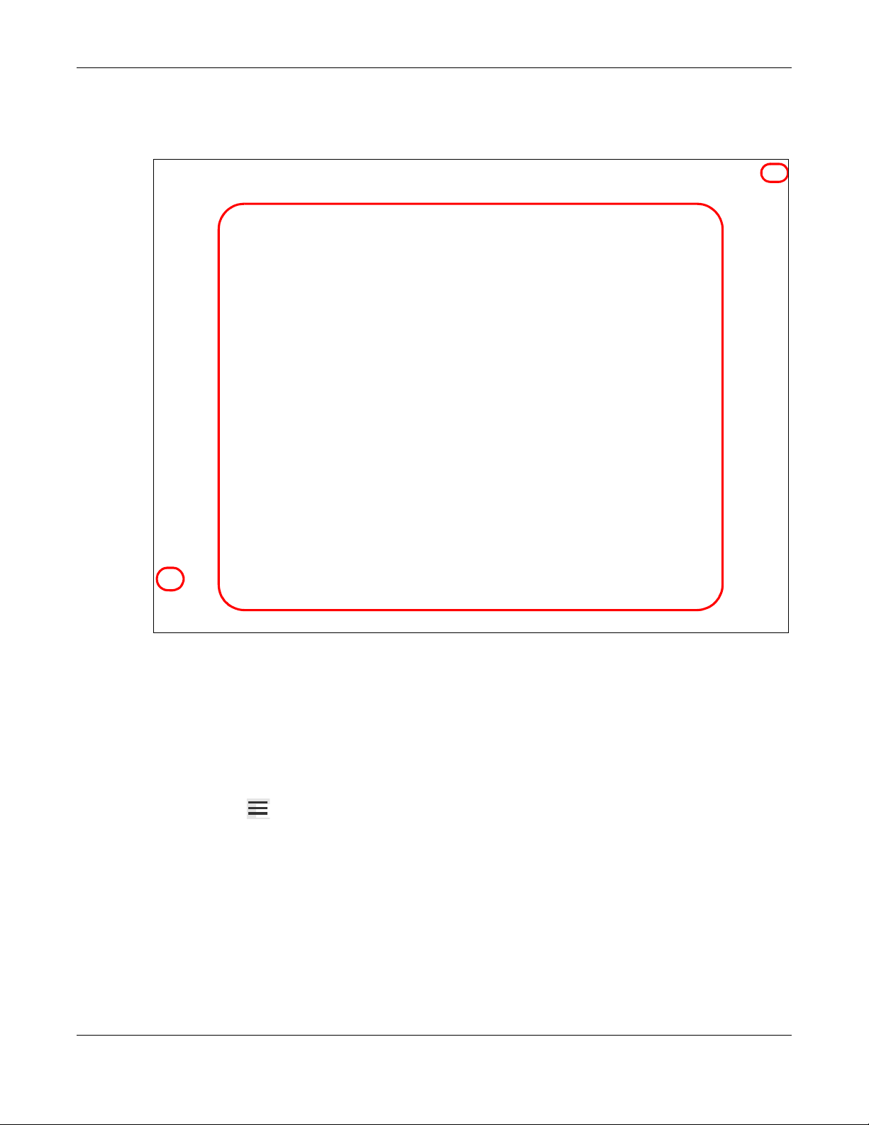
2.2 Web Configurator Layout
Figure 4 Screen Layout
2.2.1
As illustrated above, the main screen is divided into these parts:
• A - Settings Icon (Navigation Panel & Side Bar)
• B - Widget Icon
• C - Main Window
Settings Icon
Click this icon ( )
t
o see the side bar and navigation panel.
LTE7461-M602 User’s Guide
18
Page 20
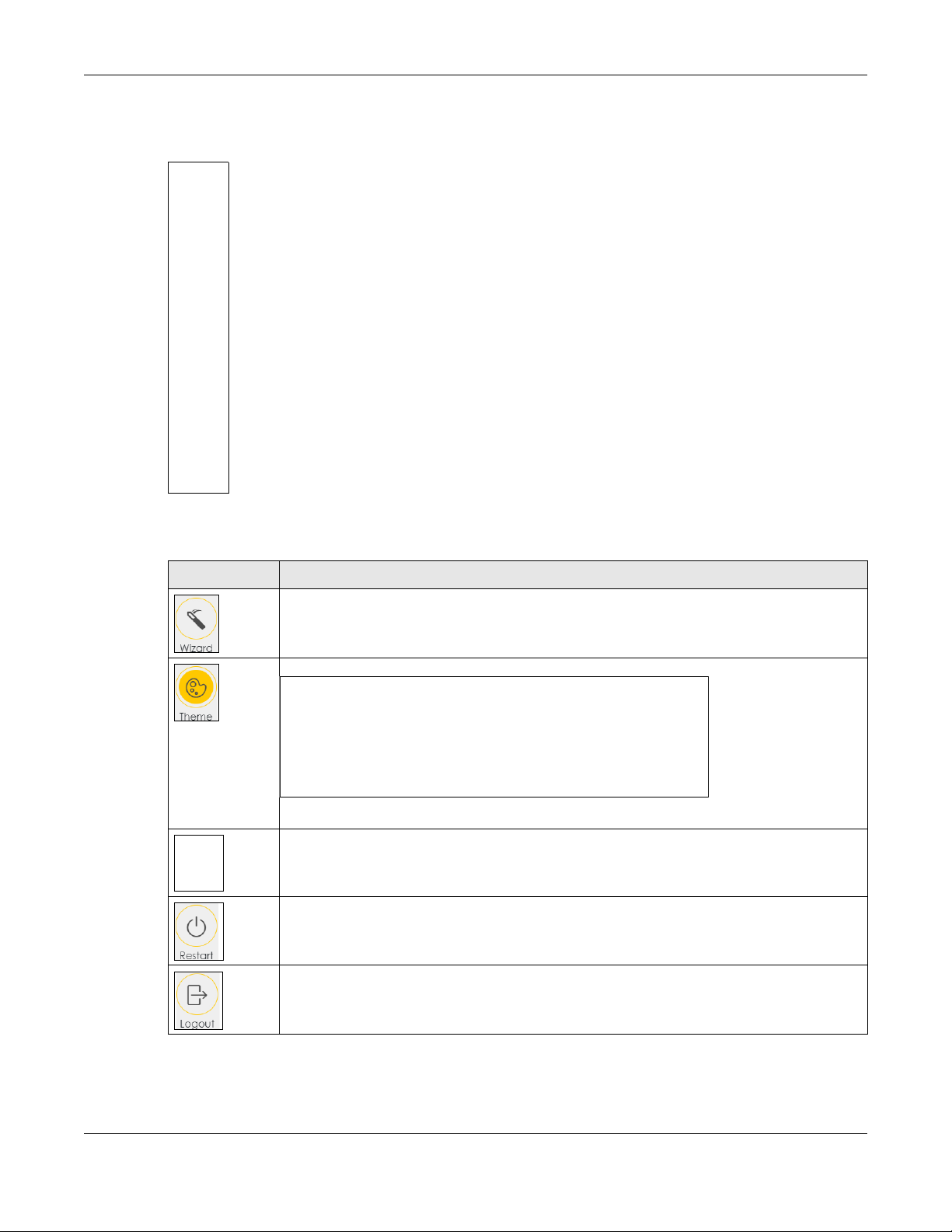
2.2.1.1 Side Bar
The side bar provides some icons on the right hand side.
Chapter 2 The Web Configurator
The icons provide the following functions.
Table 2 Web Configurator Icons in the Title Bar
ICON DESCRIPTION
Wizard: Click this icon to open screens where you can configure the Zyxel Device’s time zon e
and wireless settings. See Chapter 3 on page 23 for more information about the Wizard screens.
Theme: Click this icon to se lec t a color that you prefer an d apply it to the Web Configurator.
Language: Select the language you prefer.
Restart: Click this icon to rebo ot the Zyxel Devi c e w it hout turning the power off.
Logout: Click this icon to log out of th e W e b C o nf i gurator.
LTE7461-M602 User’s Guide
19
Page 21

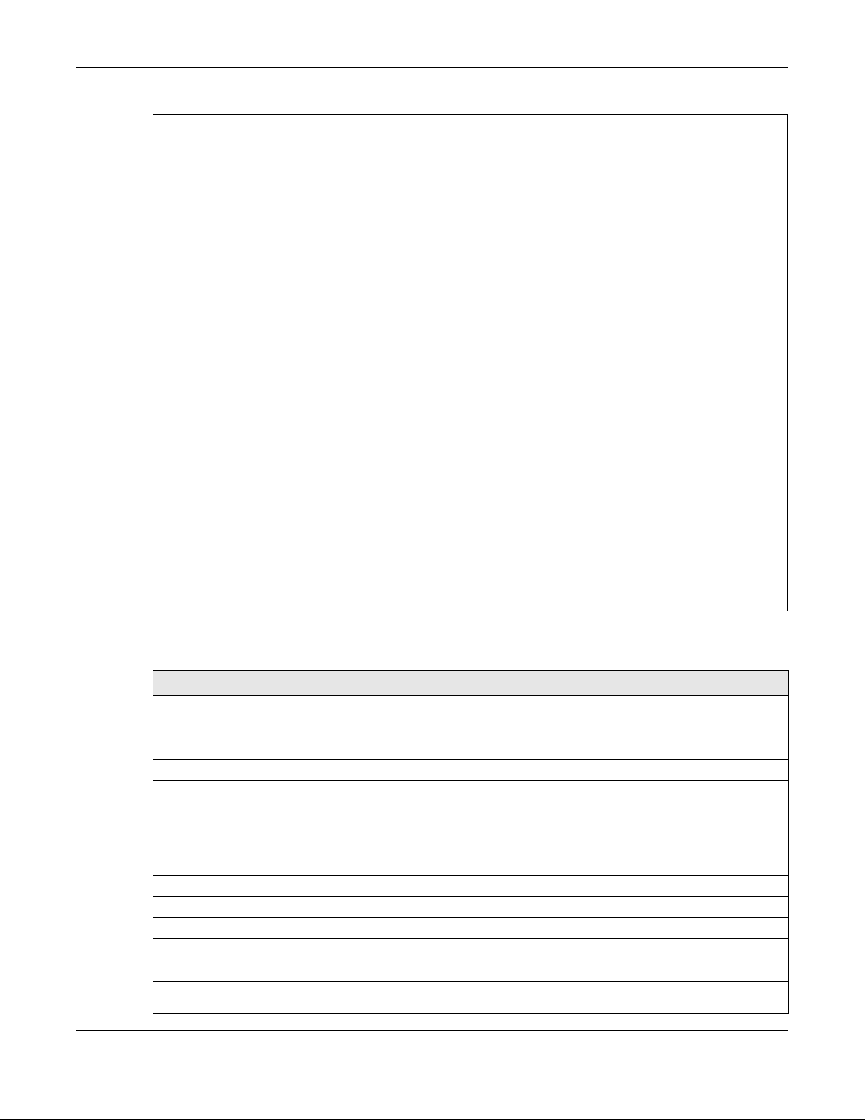
2.2.1.2 Navigation Panel
Use the menu items on the navigation panel to open screens to configure Zyxel Device features. The
following tables describe each menu item.
Table 3 Navigation Panel Summary
LINK TAB FUNCTION
Ho
me
Network Setting
adband
Bro
Wi
reless General Use this screen to configure the wireless LAN settings and WLAN
Home
Networking
Ro
uting
AT Port Forwarding
N
DN
S
curity
Se
Chapter 2 The Web Configurator
U
se this screen to configure basic Internet access and wireless settings.
This screen also shows the network status of the Zyxel Device and
computers/devices connected to it.
lular WAN
Cel
Cel
lular SIM
Cel
lular Band
lular PLMN
Cel
Cel
lular IP
Passthrough
MAC
Authentication
WPS Use this screen to configure and view your WPS (WiFi Protected Setup)
WMM Use this screen to enable or disabl e WiFi MultiMedia (WMM ) .
Others Use this screen to configure advanced wireless setting s.
nP
UP
St
atic Route
DNS Route
Policy Route
RIP
DNS
Entry
Dynamic DNS Use this screen to allow a stat ic ho s tn a me al ias for a dynamic IP addre ss.
his screen to configure an LTE WAN connection that includes the
Use t
Access Point Name (APN) provided by your service pr ov i der.
Use t
his screen to enter a PIN for your SIM card to prevent others from
using it.
Use t
his screen to configure the LTE frequency bands that can be used
for Internet access as provided by your service provider.
se this screen to view available PLMNs and select your preferred
U
network.
Use
this screen to enable IP Passthrough mode (bridge mode).
authentication/securi ty settings.
Use this screen to block or allow wireless traffic from wireless devices of
certain SSIDs and MAC addresses to the Zyxel Device.
settings.
Use this screen to configure LAN TCP/IP settings, and other advancedLAN Setup
properties.
Us
e this screen to assign specific IP addresses to individual MACStatic DHCP
addresses.
se this screen to turn UPnP and UPnP NAT-T on or off.
U
Us
e this screen to view and set up static routes on the Zyxel Device.
Us
e this screen to forward DNS queries for certain domain names through
a specific WAN interface to its DNS ser ver(s).
Use t
his screen to configure policy routing on the Zyxe l Devi ce.
U
se this screen to configure Routing Information Protocol to exchange
routing information with other routers.
this screen to make your local serve r s v is ible to the outs ide world.
Use
Use this screen to change your Zyxel Device’s port triggering settings.Port Triggering
Use this screen to configure a default server which receives packets fromDMZ
ports that are not specified in the Port Forwar d in g screen.
Use this screen to enable or disable SIP ALG.ALG
Use t
his screen to view and configur e DNS routes.
LTE7461-M602 User’s Guide
20
Page 22

Chapter 2 The Web Configurator
Table 3 Navigation Panel Summary (continued)
LINK TAB FUNCTION
Fi
rewall
MAC Filter MAC Filter Use this screen to blo c k or al low traffic from devic es of c er t ai n M AC
Sy
stem Monitor
Log Sy
Ge
neral
P
rotocol
Access Control Use this screen to enable specific traf fic d ire ctions for network services.
S
Do
Lo
cal CertificatesCertificates
Trusted CA
stem Log
rity Log
Secu
Use t
his screen to configure the security level of your fire wal l.
Use
this screen to add Internet services and configure firewall rules.
e this screen to activate protection against Denial of Service (DoS)
Us
attacks.
addresses to the Zyxel Device.
Us
e this screen to view a summ ary list of ce rti fic at es an d manage
certificates and certification requests.
se this screen to view and manage the list of the trusted CAs.
U
Use t
his screen to view the status of events that occurred to th e Zyxel
Device. You can export or email the logs.
se this screen to view all security related events. You can select the
U
level and category of the security events in their pro per drop-down list
window.
Levels include:
raffic Status
T
AR
P table
uting Table
Ro
ellular WAN
C
Status
Ma
intenance
Sy
stem
U
ser Account
Re
mote
Management
N
WA
LA
N
ARP
table
uting Table
Ro
ellular Statistics
C
Sy
stem
U
ser Account
MGMT
Services
MGMT Services
for IP Pa ss throug h
Trus
t Domain
•Emergency
•Alert
•Critical
• Error
•Warning
•Notice
•Informational
• Debugging
Categories include:
• Account
•Attack
•Firewall
•MAC Filter
se this screen to view the status of all network traffic going through the
U
WAN port of the Zyxel Device.
U
se this screen to view the status of all network traffic going through the
LAN ports of the Zyxel Device.
Use t
his screen to view the ARP table. It displays the IP and MAC address
of each DHCP connection.
his screen to view the routing table on the Zyxel Device.
Use t
e this screen to look at the cellular Internet connection status.
Us
this screen to set the Zyxel Device name and Domain name.
Use
Use t
his screen to change the user password on the Zyxel Device.
Us
e this screen to enable specific traffic dir ec t io n s for network services.
Use this sc ree n to en ab le va r io us appr o ache s t o a cc ess th is Z yxe l De vic e
remotely from a WAN and/or LAN connection.
Us
e this screen to view a list of public IP addresses which are allowed to
access the Zyxel Device through the services configured in the
Maintenance > Remote Man a gement screen.
LTE7461-M602 User’s Guide
21
Page 23

Table 3 Navigation Panel Summary (continued)
LINK TAB FUNCTION
T
R-069 Client
me
Ti
Em
ail
Notification
Setting
Log
rmware
Fi
Upgrade
ckup/Restore
Ba
2.2.2 Widget Icon
Click this icon ( ) to arrange the screen order. Select a block and hold it to move around. Click the
Check icon ( ) in the lower left corner to save the changes.
Chapter 2 The Web Configurator
T
R-069 Client
e
Tim
E
mail NotificationUse this screen to configure up to two mail servers and sender addresses
g Setting
Lo
rmware
Fi
Upgrade
up/Restore
Back
Ping&TracerouteDiagnostic
&Nslookup
Use
this screen to configure your Zyxel Device to be managed remotely
by an Auto Configuration Server (ACS) using TR-069.
this screen to change your Zyxel Device’s time and date.
Use
on the Zyxel Device.
e this screen to change your Zyxel Device’s log settings.
Us
this screen to upload firmware to your Zyxel Device.
Use
this screen to backup and restore your Zyxel Device’s configuration
Use
(settings) or reset the factory default settings.
Use this screen to reboot the Zyxel Device without turning the power off.RebootReboot
Use this screen to identify problems with the DSL connection. You can
use Ping, TraceR oute, or Nslooku p to help you identify pro blems.
LTE7461-M602 User’s Guide
22
Page 24

3.1 Overview
Use the Wizard screens to configure the Zyxel Device’s time zone and wireless settings.
N
ote: See the technical reference chapters (starting on Chapter 4 on page 53) for
background information on the features in this chapter.
3.2 Quick Start Setup
You can click the Wizard icon in the side bar to open the Wizard sc reens. Se e Sec tion 2.2.1 .1 on page 19
for more information about the side bar. After you click the Wizard icon, the following screen appears.
Click Let’s Go to proceed with settings on time zone and wir eless networks. It will take you a few minutes
to complete the settings on the Wizard screens. You can click Skip to leave the Wizard screens.
C
HAPTER
3
Quick Start
Figure 5 Wizard - Home
3.3 Time Zone
Select the time zone of your location. Click Next.
Figure 6 Wizard - Time Zone
LTE7461-M602 User’s Guide
23
Page 25

3.4 WiFi Setup
Turn the wireless LAN on or off. If you keep it on, record the WiFi Name and Password in this screen so you
can configure your wireless clients to connect to the Zyxel Device. If you want to show or hide your WiFi
password, click the Eye icon ( ).
Click Done.
Figure 7 Wizard - Wireless
Chapter 3 Quick Start
Note: You can also enable the wireless service using any of the following methods:
Click Network Setting > Wireless to open the General screen. Then select Enable in the
Wireless field. Or,
Press the WiFi button located under the RESET button (see Section 1.6 on page 14 for the
location) for one second.
3.5 Quick Start Setup-Finish
Your Zyxel Device saves your settings and attempts to connect to the Internet.
LTE7461-M602 User’s Guide
24
Page 26

PART II
Technical Reference
25
Page 27

Connection Status Screens
4.1 The Connection Status Screen
After you log into the Web Configurator, the Connection Status screen appears. You can configure
basic Internet access and wireless settings in this screen. It also shows the network status of the Zyxel
Device and computers/devices connected to it.
C
HAPTER
4
4.1.1
The Connectivity Screen
Use this screen to view the network connection status of the Zyxel Device and its clients.
Figure 8 Connectivity
Click the Arrow icon ( ) to view IP addresses and MAC addresses of the wireless and wired devices
connected to the Zyxel Device.
Figure 9 Connectivity: Connected Devices
You can change the icon and name of a connect ed device. Place your mouse within the device
block, and an Edit icon ( ) will appear. Click the Edit icon, and you’ll see there are several icon
choices for you to select. Enter a name in the Device Name field for a connec te d d ev i ce . Clic k Save to
save your changes.
LTE7461-M602 User’s Guide
26
Page 28

Chapter 4 Connection Status Screens
Figure 10 Connectivity: Edit
4.1.2 The System Info Screen
Use this screen to view the basic system information of the Zyxel Device.
Figure 11 System Info
Click the Arrow icon ( ) to view the more information on the status of your firewall and interfaces (WAN,
LAN, and WLAN).
LTE7461-M602 User’s Guide
27
Page 29
Chapter 4 Connection Status Screens
Figure 12 System Info: Detailed Information
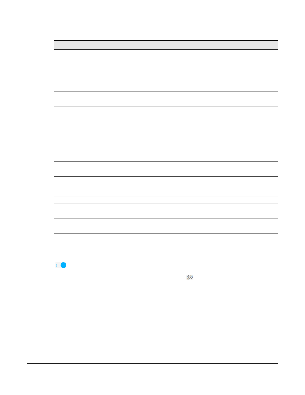
Each field is described in the following table.
Table 4 System Info: Detailed Information
LABEL DESCRIPTION
ost Name This field displays the Zyxel Device sys t em n ame. It is used for identific at io n.
H
This shows the mode l nu mber of your Zyxel Device.Model Name
This field displays the serial number of the Zyxe l Device.Serial Number
This is the current version of the firmware inside the Zyxel Device.Firmware Version
This field display s ho w lo ng the Zyxel Device ha s been running since it last star t ed up. TheSystem Up Time
Zyxel Device sta rts up when you plug it in, when yo u r es ta r t it (Maintenance > Reboot), or
when you reset it.
Interface Status
Virtual ports are shown here. You can see the ports in use and their transmission rate.
WAN Information (These fields display when you have a WAN connection.)
Mode This field display s th e cur r ent mode of your Zyxel Dev ice.
This field display s the c urrent IP address of the Zy x el Device in the WAN.IP Address
This field displays the current subnet mask in the W AN.IP Subnet Mask
This field displays the current IPv6 address of the Zyxel Device in the WAN .IP v6 Add ress
Primary DNS
server
This field displays th e fir st DN S se rv er ad dr e s s ass igned by the ISP.
LTE7461-M602 User’s Guide
28
Page 30
Chapter 4 Connection Status Screens
Table 4 System Info: Detailed Information (continued)
LABEL DESCRIPTION
Se
condary DNS
server
Primary DNSv6
server
Secondary
DNSv6 server
LAN Information
Security
WLAN Information
Status This displays whether the WLAN is activated.
D
SSI
hannel
C
Se
curity
802.
11 Mode
WPS This displa y s wh et her WPS is activated o n th e w ireless interface.
This field displays the second DNS server address assigned by the ISP.
This field display s th e firs t DN S se r v er IPv6 address assign ed by the ISP.
This field displays the second DNS server IPv6 address assigned by the ISP.
This is the current IP address of the Zyxel Dev ice in the LAN.IP Address
This is the current subnet mask in the LAN.Subnet Mask
This field display s wh at DHCP services the Zyxel Dev i c e is prov i di ng to the LAN. The possibleDHCP
values are:
Server - The Zyxel Device is a DHCP server in the LAN. It assigns IP addresses to other
computers in the LAN.
Relay - The Zyxel Device acts as a surrogate DHCP ser ver and relays DHCP requests an d
responses between the remote server and the clients.
None - The Zyxel Device is not providing any DHCP services to the LAN.
This displays the f ire wall’s current sec urity level.Firewall
This shows the wireless adapter MAC (Media Access Control) Address of the wirelessMAC Address
interface.
is is the descriptive name used to identify th e Zyx el Device in a wireless LAN.
Th
is is the channel number currently used by the wireless interface.
Th
Th
is displays the ty p e of security mode the wireless interfac e is using in the wireless LAN.
T
his displays the type of 802.11 mode the wireless interface is using in the wireless LAN.
4.1.3 The WiFi Settings Screen
Use this screen to enable or disable the main 2.4 GHz wireless network. When the switch turns blue
( ), the function is enabled. Otherwise, it’s not. You can use th is screen or the QR code on the upp er
right corner to check the SSIDs (WiFi network name) and passwords of the main wireless networks. If you
want to show or hide your WiFi passwords, click the Eye icon ( ).
LTE7461-M602 User’s Guide
29
Page 31

Chapter 4 Connection Status Screens
Figure 13 WiFi Settings
Click the Arrow ic on ( ) to configure the SSIDs an d/or passwords for your main wireless networks. Click
the Eye icon ( ) to display the characters as you enter the WiFi Password.
Figure 14 WiFi Settings: Configuration
Each field is described in the following table.
Table 5 WiFi Settings: Configuration
LABEL DESCRIPTION
.4G WiFi Click this switch to enable or disable the 2.4 GHz wireless network. When the switch turns blue
2
, the function is enabled. Otherwise, it’s not.
WiFi Name The SSID (Service Set IDentity) identifies the service set with which a wireless device is
associated. Wireless devices associating to the access point (AP) must have the same SSID.
Enter a descriptive name (up to 32 English keyboard characters) for the wireless LAN.
If you selectedWiFi Password Random Password, this fie ld dis plays a pre- share d key generate d by the Z yxel
Device.
If you did not select Random Password, you can manually type a pr e-shared key from 8 to 64
case-sensitive keyboard characters.
Click the Eye ic on t o sh ow o r hide t he p ass wo rd f o r yo ur w i rel es s n etw ork. Wh en t he Eye ic on
is slashed , you’ll see the pa s s word in plain text. Ot he r wis e, it’s hidden.
LTE7461-M602 User’s Guide
30
Page 32

Chapter 4 Connection Status Screens
Table 5 WiFi Settings: Configuration (continued)
LABEL DESCRIPTION
S
elect this option to have the Zyxel De vice automatically generate a password. TheRandom Password WiFi
Password field will n ot be configurable when you select th is option.
Hide WiFi network
name
ve Click Save to save your changes.
Sa
Select this check box to hide the SSID in the outgoing beacon frame so a station cannot
obtain the SSID through scanning using a site survey tool.
Note: Disable WPS in the Network Setting > Wireless > WPS screen to hide the SSID.
4.1.4
The LAN Screen
Use this screen to view the LAN IP address, subnet mask, and DHCP settings of your Zyxel Device.
Figure 15 LAN
Click the Arrow icon ( ) to configure the LAN IP settings and DHCP setting for your Zyxel Device.
Figure 16 LAN Setup
LTE7461-M602 User’s Guide
31
Page 33

Chapter 4 Connection Status Screens
Each field is described in the following table.
Table 6 Status Screen
LABEL DESCRIPTION
LA
N IP Setup
Enter the LAN IPv4 IP address you want to assign to your Zyxel Device in dotted decimalIP Address
notation, for example, 192.168.1.1 (factory default).
Type the subnet mask of your network in dotted decimal notation, for example 255.255.255.0Subnet Mask
(factory default). Your Zyxel Dev ice automatica lly c om putes the subnet mas k bas ed on the
IP Address you enter, so do not change this field unless you are instructed to do so.
IP Addressing Values
Beginning IP
Address
Ending IP
Address
DHCP Server State
DHCP Server
Lease Time
Days/Hours/
Minutes
This field specifies the first of the contiguous addresses in the IP address pool.
This field specifies the last of the contiguous addresses in the IP address pool.
This is the period of time DHCP-assigned addresses is used. DHCP automatically assigns IP
addresses to clients when they log in. DHCP centralizes IP address management on central
computers that run the DHCP server program. DHCP leases addresses, for a period of time,
which means that past addresses are “recycled” and made available for future
reassignment to other systems.
Enter the lease time of the DHCP server.
ClickSave Save to save your changes.
LTE7461-M602 User’s Guide
32
Page 34

5.1 Overview
This chapter discusses the Zyxel Device’s Broadband screens. Use these screens to configure your Zyxel
Device for Internet access.
A WAN (Wide Area Network) connection is an outside connection to another network or the Internet. It
connects your private networks, such as a LAN (Local Area Network) and other networks, so that a
computer in one location can communicate with computers in other locations.
Figure 17 LAN and WAN
C
HAPTER
5
Broadband
5.1.1
5.1.2
What You Can Do in this Chapter
• Use the Cellular WAN screen to configure an LTE WAN connection (Section 5.2 on page 34).
• Use the Cellular SIM screen to enter the PIN of your SIM card (Section 5.3 on page 36).
• Use the Cellular Band screen to view or edit an LTE WAN interface. You can also configure the WAN
settings on the Zyxel Device for Internet access (Section 5.4 on page 37).
• Use the Cellular PLMN screen to display available Public Land Mobile Networks (Section 5.5 on page
38).
• Use the Cellular IP Passthrough screen to confi gure an LTE WAN co nnection (Section 5.6 on page 40).
What You Need to Know
The following terms and concepts may help as you read th is chapter.
LTE7461-M602 User’s Guide
33
Page 35

Chapter 5 Broadband
WAN IP Address
The WAN IP address is an IP address for the Zyxel Device, which makes it accessible from an outside
network. It is used by the Zyxel Device to communicate with other devices in other networks. The ISP
dynamically assigns it each time the Zyxel Device tries to access th e Internet.
APN
Access Point Name (APN) is a unique string which indicates an LTE network. An APN is required for LTE
stations to enter the LTE network and then the Internet.
5.1.3
Before You Begin
You may need to know your Internet access settings such as LTE APN, WAN IP address and SIM card’s
PIN code if the INTERNET light on your Zyxel Device is off. Get this information from your service provider.
5.2 The Cellular WAN Screen
Click Network Setting > Broadband > Cellular WAN to display the following screen. Configure an LTE
connection, including the Access Point Name (APN) provided by your service provider.
Note: APN information can be obtained from the service provider.
LTE7461-M602 User’s Guide
34
Page 36

Chapter 5 Broadband
Figure 18 Network Setting > Broadband > Cellular WAN
N
ote: Roaming charges may apply when Data Roaming is enabled.
Automatic APN Mode is not supported when operating in 3G only mode.
The following table describes the fields in this screen.
Table 7 Network Setting > Broadband > Cellular WAN
LABEL DESCRIPTION
aming
Ro
Click this to enable ( ) data roaming on the Zyxel Device.Data Roaming
4G roaming is to use your mobile device in an area which is not covered by your service provider.
Enable roaming to ensure that your Zyxel Device is kept connected to the Inter net when you are
traveling outside the geographical coverage area of the network to which you are registered.
APN Settings
APN Manual
Mode
Disable this to have the Zyxel Device configure the APN (Access Point Name) of an LTE network
automatically. Otherwise, Click this to ena ble ( ) and enter the APN manually in the fiel d
below.
This field allow s yo u to dis play the Access Po int Name (APN) in th e p rofile.APN
Enter the Access Point Name (A PN) provi ded by your service provider. Connecti ons wit h differ ent
APNs may provid e diff e r en t se rv ices (such as Internet acc e ss or MM S ( M ul ti -M ed ia Messaging
Service)) and char gi ng met hod.
You can enter up to 30 printable ASCII characters. Spaces are allo wed .
LTE7461-M602 User’s Guide
35
Page 37

Chapter 5 Broadband
Table 7 Network Setting > Broadband > Cellular WAN (continued)
LABEL DESCRIPTION
Th
is field allows you to dis p lay th e us er name in the profile.Username
Type the user name (up to 31 printable ASCII characters) given to you by your service provider.
This field allows you to set the password in the profile.Password
Type the password (up to 31 printable ASCII characters) associated with the user name above.
Authentication
Type
Select the type of authentication method peers use to con ne ct to the Zyxel Device in LTE
connections.
In Password Aut hentication Pro tocol (PAP) peers identify themselves with a user name and
password. In Challenge Handshake Authentication Protocol (CHAP) additionally to user name
and password the Zy xel Device sends regular challenges to make sure an intruder has not
replaced a peer. Otherwise select PAP/CHAP or None.
SelectPDP Type IPv4 if you want the Zyxel Device to run IPv4 (Internet Protocol vers ion 4 addressing sy stem)
only.
Select IPv4/IPv6 if you want the Zyxe l De vice to run both I Pv 4 an d IP v6 (I n ter net P r otoc ol ver si on 4
and 6 addressing system) at the same time.
Click this to save your changes.Apply
Click this to exit thi s scr een without savi ng .Cancel
5.3 The Cellular SIM Configuration Screen
Enter a PIN for your SIM card to prevent others from using it.
Entering the wrong PIN code 3 consecutive times locks the SIM card
after which you need a PUK (Personal Unlocking Key) from the service
provider to unlock it.
Click Network Setting > Broadband > Cellular SIM. The following screen opens.
Figure 19 Network Setting > Broadband > Cellular SIM
Note: The PIN is automatically saved in the Zyxel Device.
Entering the wrong PIN exceeding a set number of times will lock the SIM card.
LTE7461-M602 User’s Guide
36
Page 38

Chapter 5 Broadband
The following table describes the fields in this screen.
Table 8 Network Setting > Broadband > Cellular SIM
LABEL DESCRIPTION
PI
N Management
PI
N ProtectionA PIN (Personal Identification Number) code is a key to a SI M c ar d. Without the PIN code, you
cannot use the SIM card.
Click to enable ( ) if the service provider requires you to enter a PIN to use the SIM card.
Click to disab le if the service pr ovider lets you use the SIM without inputting a PIN.
PIN If you enabled PIN verification, enter the 4-digit P IN code (0000 for example) provided by your ISP.
Attempts
Remaining
Ap
ply
Cancel Click Cancel to return to the previous screen without saving.
If you enter the P IN co d e incorrectly too m an y tim es, the ISP may bl ock your SIM card an d not let
you use the account to access the Internet.
This is how many more times you can try to enter the PIN code before the ISP blocks your SIM card.
Cl
ick Apply to save your changes.
5.4 The Cellular Band Configuration Screen
Either select Auto to have the Z y x el Device connect to an available network using the default settings
on the SIM card or select the type of the network (4G, 3G, or 2G) to which you want the Zyxel Device to
connect.
Click Network Setting > Broadband > Cellular Band. The following sc reen opens.
Figure 20 Network Setting > Broadband > Cellular Band
LTE7461-M602 User’s Guide
37
Page 39

Chapter 5 Broadband
The following table describes the fields in this screen.
Table 9 Network Setting > Broadband > Cellular Band
LABEL DESCRIPTION
Ac
cess Technology
Preferred Access
Technology
Band Management
Select the type of the network (4G, 3G, or 2G) to which you want th e Z y x e l Device to
connect and click Apply to save your settings.
Otherwise, select Auto to have the Zyxel Device connect to an available network using the
default sett ings on the SIM c ard. If the curr ently registered mobile network is not available or
the mobile network’s signal strengt h is to o lo w , th e Zy x el Device switches to an o th er
available mobile network.
Select the LTE bands to use for the Zyxel Device’s WAN connection. Click to e nable ( )Band Auto Sele c tion
automatic LTE fr equency band selection as provided by your service provid er. Otherwise,
select disabled.
Click this to sa v e yo ur c ha nges.Apply
Click this to ex it this screen without saving.Cancel
5.5 PLMN Configuration Screen
Each service provider has its own unique Public Land Mobile Network (PLMN) number. Eit her select PLMN
Auto Selection to have th e Zyxel Devi ce con nect to the servi ce pro vider using t he d efault sett ings o n the
SIM card or manually view available PLMNs and select your service provider.
Click Network Setting > Broadband > Cellular PLMN. The screen appears as shown next.
Figure 21 Network Setting > Broadband > Cellular PLMN
The following table describes the labels in this screen.
Table 10 Network Setting > Broadband > Cellular PLMN
LABEL DESCRIPTION
P
LMN Management
Click to enable ( ) and have the Zyxel Device automatically connect to the firstPLMN Auto Selection
available mobile network.
Select disabled to display the network list and manually select a preferred network.
ClickApply Apply to save your changes back to the Zyxel Device.
ClickCancel Cancel to exit this screen without saving.
After selecting to disable the following warning appears. Click OK to continue.
LTE7461-M602 User’s Guide
38
Page 40

Chapter 5 Broadband
Figure 22 Network Setting > Broadband > Cellular PLMN > Manual Scan Warning
When the next screen ap pea rs, c lick ing Scan will allow the Zyxel Device to check for available PLMNs in
its surroundings and display the network list.
Figure 23 Network Setting > Broadband > Cellular PLMN > Manual Scan
LTE7461-M602 User’s Guide
39
Page 41

Chapter 5 Broadband
The following table describes the labels in this screen.
Table 11 Network Setting > Broadband > Cellular PLMN > Manual Scan
LABEL DESCRIPTION
# C
Status This shows Current to show the ISP the Zyxel Device is currently connected to.
Name This shows the ISP name.
Type This shows the type of networ k the ISP provides.
PLMN This shows the PLMN number.
Apply Click Apply to save your changes back to the Zyxel Device.
Cancel Click Cancel to exit this screen without saving.
Select from the network list and click Apply.
lick the radio button so the Zyxel Device connects to this ISP.
This shows Forbidden to indicate the Zyxel Device cannot connect to this ISP.
This shows Available to indicate an available ISP your Zyxel Device can connect to.
5.6 IP Passthrough Screen
Enable IP Passthrough to allow Internet traffic to go to a LAN computer behind the Zyxel Device without
going through NAT.
Click Network Setting > Broadband > Cellular IP Passthrough to display the following screen.
Figure 24 Network Setting > Broadband > Cellular IP Passthrough
ote: Changing the IP Passthrough settings may affect the network setting of client devices.
N
After selecting to enable the following warning appears. Click OK to continue.
LTE7461-M602 User’s Guide
40
Page 42

Chapter 5 Broadband
Figure 25 Network Setting > Broadband > Cellular IP Passthrough > Enable Warning
The following table describes the fields in this screen.
Table 12 Network Setting > Broadband > IP Passthrough
LABEL DESCRIPTION
I
P Passthrough Manage ment
IP Passthrough allows a LAN computer on the local network of the Zyxel Device to have access toIP Passthrough
web services using the public IP address. When IP Passthrough is configured, all traffic is forwarded
to the LAN computer and will not go through NAT.
Passthrough
Mode
Select Dynamic to allow traffic to be forwarded to any LAN computer on the local network of the
Zyxel Device. Select Fixed to allow traffic to be forwarded to a specific LAN computer on the local
network of the Zyxel Device.
Note: This field will show upon enabling IP Passthrough in the previous field.
P
assthrough
to fixed MAC
Enter the MAC Address of a LAN computer on the lo cal network of the Zyxel Device upon
selecting Fixed in the previous field.
Note: This field will show upon selecting Fixed in the previous field.
Apply Click th is to save your chang es .
Click this to ex it this screen without saving.Cancel
LTE7461-M602 User’s Guide
41
Page 43

6.1 Overview
This chapter describes the Zyxel Device’s Network Setting > Wireless screens. Use these screens to set up
your Zyxel Device’s WiFi network and security settings.
C
HAPTER
Wireless
6
6.1.1
6.1.2
What You Can Do in this Chapter
This section describes the Zyxel Device’s Wireless screens. Use these screens to set up your Zyxel Device’s
WiFi connection.
• Use the General screen to enable the Wireless LAN, enter the SSI D and select the WiFi security mode
(Section 6.2 on page 43).
• Use the MAC Authentication screen to allow or deny wireless clients based on their MAC addresses
from connecting to the Zyxel Device (Section 6.3 on page 46).
• Use the WPS screen to enable or disable WPS, view or generate a security PIN (Personal Identification
Number) (Section 6.4 on page 48).
• Use the WMM screen to enable WiFi MultiMedia (W MM) to ensure quality of service in WiFi networks for
multimedia applications (Section 6.5 on p age 49).
• Use the Others screen to configure WiFi a dvanced features, suc h as th e RTS/CTS Thr eshold (Section 6.6
on page 50).
What You Need to Know
Wireless Basics
“Wireless” is essentially radio communication. In the same way that walkie-talkie radios send and
receive information over the airwaves, wireless networking devices exchange information with one
another. A wireless networking devic e is ju st like a radio that lets your computer exchange information
with radios attached to other computers. Like walkie-talkies, most wireless networking devices operate
at radio frequency bands that are open to the public and do not require a license to use. However,
wireless networking is different from that of most traditional radio communications in that there are a
number of wireless networking standards available with different methods of data encryption.
Finding Out More
See Section 6.7 on page 52 for advanced technical information on WiFi networks.
LTE7461-M602 User’s Guide
42
Page 44

6.2 The General Screen
A WiFi network name (also known as SSID) and a security level are basic elements of a WiFi network. Set
a Security Level to protect your data from unauthorized access or damage via WiFi. Use this screen to
enable WiFi, enter the SSID and select the WiFi security mode. It’s recommended that you select More
Secure to enable WPA2-PSK data encryption.
ote: If you are configuring the Zyxel Device fr om a co mputer co nnected to the wireless L AN
N
and you change the Zyxel Device’s SSID, channel or security settings, you will lose your
connection when you press Apply to confirm. You must then change the
WiFi
settings of your computer to match the Zyxel Device’s new settings.
Click Network Setting > Wireless to open the General screen.
Figure 26 Network Setting > Wireless > General
Chapter 6 Wireless
WiFi
LTE7461-M602 User’s Guide
43
Page 45

Chapter 6 Wireless
The following table describes the general wireless LAN labels in this screen.
Table 13 Network Setting > Wireless > General
LABEL DESCRIPTION
Wi
Fi Network Setup
Ba
nd
Fi
Wi
C
hannel
Bandwidth Select whether the Zyxel Device uses a
Th
is shows the WiFi band which this radi o pr o file is using. 2.4GHz is the frequency used by IEEE
802.11b/g/n WiFi clients while 5GHz is used by IEEE 802.11a/ac WiFi clients.
ick Enable to enable the wireless LAN in this field.
Cl
Us
e Auto to have the Zyxel Device automatically determine a channel to use.
channel width of 20MHz, 40MHz or 20/40MHz.
WiFi
A standard 20MHz channel offers transfer speeds of up to 150Mbps whereas a 40MHz channel
uses two standard channels and offers speeds of up to 300Mbps.
40MHz (channel bonding or dual channel) bonds two adjacent radio channels to increase
throughput. The WiFi clients must also support 40MHz. It is often better to use the 20MHz setting in
a location where the environment hinders the
WiFi
si
gnal.
Select 20MHz if you want to lessen radio interference with other
neighborhood or the
ntrol
Co
Sideband
Fi Network Settings
Wi
Wi
Fi Network
Name
Max Clients Specify the maximum number of cl ients that can connect to this net wor k at the same time.
de SSID
Hi
Multicast
Forwarding
BS
SID
curity Level
Se
Se
curity Mode
is is available for some regions when you select a specific channel and set the Bandwidth field
Th
to 40MHz. Set whether the control ch annel (set in the Channel field) should be in the Lower or
Upper range of channel bands.
Th
e SSID (Service Set IDentity) identifies the service set with which a
WiFi devices associating to the access point (AP) must have the same SSID.
Enter a descriptive name (up to 32 English keyboard characters) for the wireless LAN.
elect this check box to hide the SSID in the outgoing beacon frame so a station cannot obtain
S
the SSID through scanning using a site survey tool.
This check box is grayed out if the WPS function is enabled in the Network > Wireless > WPS
screen.
Select this check box to allow the Zyxel Device to convert wireless multicast traffic into wireless
unicast traffi c .
T
his shows the MAC address of the wireless interface on the Zyxel Device when wireless LAN is
enabled.
Sel
ect More Secure (WPA2-PSK) to add security on this
to associate to this network must have the same
you select to use a security, additional options appears in this screen.
Or you can select No Security to allow any client to associate with this network without any data
encryption or authentication.
clients do not support channel bonding.
WiFi
WiFi
WiFi
security settings as the Zyxel Device. When
WiFi
ne
twork. The
vices in your
de
de
vice is associated .
WiFi
WiFi
clients which want
6.2.1
See the follow ing s ec t io ns fo r more details abou t th is f iel d.
Ca
Ap
ncel
ply
Cl
ick Cancel to restore your previously save d s ettings.
Cl
ick Apply to save your changes.
No Security
Select No Security to allow wireless stations to com municate with the access points without any data
encryption or authentication.
LTE7461-M602 User’s Guide
44
Page 46

Chapter 6 Wireless
6.2.2
te: If you do not enable any
No
ecurity on your Zyxel Device, your network is accessible to
s
WiFi
any wireless networking device that is within range.
Figure 27 Wireless > General: No Security
The following table describes the labels in this screen.
Table 14 Wireless > General: No Security
LABEL DESCRIPTION
curity Level
Se
hoose No Security to allow all
C
WiFi
onnections without data encryption or authentication.
c
More Secure (WPA2-PSK)
The WPA2-PSK security mode is a newer, more robust version of the WPA encryption standard. It offers
slightly better security, although the use of PSK makes it less robust than it could be. Using a Pre-Shared
Key (PSK), both the Zyxel Device and the connecting client share a common password in order to
validate the connection.
Click Network Setting > Wireless to display the General screen. Select More Secure as the security level.
WPA2-PSK is the defa ult Security Mode.
Figure 28 Wireless > General: More Secure: WPA2-PSK
LTE7461-M602 User’s Guide
45
Page 47

Chapter 6 Wireless
The following table describes the labels in this screen.
Table 15 Wireless > General: More Secure: WPA2-PSK
LABEL DESCRIPTION
Se
curity Level
Se
curity Mode
Generate
password
automatically
assword
P
Sel
ect More Secure to enable WPA2-PSK data encryption.
WP
A2-PSK is the default security mode.
Select this option to have the Zyxel Device automatically generate a password. The password
field will not be co nfigurable when yo u s e lect this option.
ect Generate password automatically or enter a Password.
Sel
The password has tw o us es.
1. Manual. Manually enter the same password on the Zyxel Device and the client. Enter 8-63
ASCII characters or exactly 64 hexadecimal (‘0-9’, ‘a-f’) characters.
2. WPS. When using WPS, the Zyxel Device sends this password to the client.
Note: Enter 8-63 ASCII characters only. 64 hexadecimal characters are not accepted
for WPS.
C
lick the Eye icon to show or hide the password f or your wireless network. When the Eye icon is
slashed , you’ll see the pass w o rd in plain text. Otherwise, it’s hidden.
re...
mo
En
cryption
Ti
mer
lick this to show more fields in this section. Click this to hide them.
C
AE
S is the default data encryption type, which uses a 128-bit key.
Th
is is the rate at which the RADIUS server sends a new group key out to all clients.
6.3 MAC Authentication
Configure the Zyxel Device to give exclusive access to specific devices (Allow) or exclude specific
devices from accessing the Zyxel Device (Deny) based on the device(s) MAC address. Every Ethernet
device has a unique MAC (Media Access Control) address. It is assigned at the fact o ry an d co ns is t s of
six pairs of hexadecimal characters; for example, 00:A0:C5:00:00:02. You need to know the MAC
addresses of the device(s) you want to allow/deny to configure this screen. Edit the list in the table to
decide the rule of access on device(s).
LTE7461-M602 User’s Guide
46
Page 48

Chapter 6 Wireless
Use this screen to view your Zyxel Device’s MAC filter settings and add new MAC filter rules. Click
Network Setting > Wireless > MAC Authentication. The screen appears as shown.
Figure 29 Network Setting> Wirel ess > MAC Authentication
The following table describes the labels in this screen.
Table 16 Network Setting> Wireless > MAC Authentication
LABEL DESCRIPTION
neral
Ge
SSI
D
MA
C Restrict
Mode
MAC address List
dd new MAC
A
address
# Th
MAC Address This is the MAC addresses of the
M
odify
S
elect the SSID for which you want to configure MAC filter settings.
D
efine the filter action for the list of MAC addresses in the MAC Address tabl e .
Select Disable to turn off MAC filtering.
Select Deny to block access to the Zyxel Device. MAC addresses not listed will be allowed to
access the Zyxel Device.
Select Allow to permit access to the Zyxel Device. MAC addresse s not listed will be de nied
access to the Zyxel Device.
is field is available when you select Deny or Allow in the MAC Restrict Mode field.
Th
Click this if you want to add a new MAC addres s entry to the MAC filt er list below.
Enter the MAC addresses of the
Device in these address fields. Enter the MAC addresses in a valid MAC address format, that is,
six hexadecimal character pairs, for example, 12:34:56:78:9a:bc.
is is the index number of the entry.
Device.
Cl
ick the Edit icon and type the MAC address of the peer device in a valid MAC address format
(six hexadecimal character pairs, for example 12:34:56:78:9a:bc).
de
vices that are allowed or denied access to the Zyxel
WiFi
devices that are allowed or denied access to the Zyxel
WiFi
Click the Delete icon to delete the entry.
ncel Click Cancel to exit this screen without saving.
Ca
ply Click Apply to save your changes.
Ap
LTE7461-M602 User’s Guide
47
Page 49

6.4 The WPS Screen
Use this screen to configure WiFi Protected Setup (WPS) on your Zyxel Device.
WiFi Protected Setup (WPS) allows you to quickly set up a WiFi network with strong security, without
having to configu re security settings manually. Select one of the WPS methods and follow the
instructions to establish a WPS connection. To set up a WPS connection between two devices, both
devices must support WPS. It is recommended to use the Push Button Configuration (PBC) method if your
WiFi client supports it. See Section 6.7.7.3 on page 60 for more information about WPS.
No
te: The Zyxel Device uses the security settings of the SSID1 profile (see Section 6.2.2 on page
The WPS button will gray-out when wireless LAN or WPS is disabled.
45).
ote: If WPS is enabled, UPnP will automatically be turned on.
N
Click Network Setting > Wireless > W PS. The following screen displays. Click this switch and it will turn blue.
Click Apply to activate the WPS function. Then you can configure the WPS settings in this screen.
Figure 30 Network Setting > Wireless > WPS
Chapter 6 Wireless
LTE7461-M602 User’s Guide
48
Page 50

Chapter 6 Wireless
The following table describes the labels in this screen.
Table 17 Network Setting > Wireless > WPS
LABEL DESCRIPTION
Ge
neral
Click to enable ( ) and have the Zyxel Device activate WPS. Otherwise, it is disabled.WPS
Add a new device with WPS Me thod
Use this section to set up a WPS WiFi network using Push Button Configuration (PBC). Click thisMethod 1 PBC
switch to make it turn blue. Click Apply to activate WPS method 1 on the Zyxel Device.
Click this button to add another WPS-enabled WiFi device (within WiFi range of the ZyxelWPS
Device) to your WiFi network. This button may either be a physical button on th e ou tside of a
device, or a menu button similar to the WPS button on this screen.
Note: You must press the other WiFi device’s WPS button within two minutes of
pressing this button.
Us
e this section to set up a W PSMethod 2 PIN
Device. Click this switch to make it turn blue. Click Apply to activate WPS method 2 on the Zyxel
Device.
Enter the PIN of the device that you are setting up a WPS connection with and clickRegister Register to
authenticat e and add the WiFi devi c e to your WiFi netwo rk.
You can find the PIN either on the outside of the device, or by checking the device’s settings.
WiFi
n
etwork by entering the PIN of the client into the Zyxel
Note: You must also activate WPS on that device within two minute s to have it
present its PIN to the Zyxel Device.
Method 3 Use this sectio n to set up a W PS W iF i ne t w o r k by entering the PIN of the Zyxel Device into the
Release
Configuration
Generate
New PIN
Cancel Click Cancel to restore your previously saved settings.
pply Click Apply to save your changes.
A
client. Click th is switch to make it turn b lu e . Click Apply to activate WPS method 3 on the Zyxel
Device.
The default WPS sta tu s is con fig u r ed .
Click this button to remove all configured WiFi and WiFi security settings for WPS connections on
the Zyxel Device.
If this method has been en abled, the PIN (Persona l Iden tific ation Number ) of the Zy xel Devi ce is
shown here. Enter this PIN in the configuration utility of the device you want to connect to using
WPS.
The PIN is not necessary when you use the WPS push-button method.
Click the Generate New PIN button to have the Zyxel Device create a new PIN.
6.5 The WMM Screen
Enable Wi-Fi MultiMedia (WMM) and WMM Automatic Power Save (APSD) in WiFi networks for delaysensitive multimedia applications. WMM enhances data transmission quality which allows delay-sensitive
applications, such as videos, to run more smoothly. APSD improves power management of WiFi mobile
clients. APSD works only if the WiFi device to which the Zyxel Device is connected also supports this
feature.
Click Network Setting > Wireless > WMM to display the following screen.
LTE7461-M602 User’s Guide
49
Page 51

Chapter 6 Wireless
Figure 31 Network Setting > Wireless > WMM
No
te: WMM cannot be disabled if 802.11 mode includes 802.11n or 802.11ac.
The following table describes the labels in this screen.
Table 18 Network Setting > Wireless > WMM
LABEL DESCRIPTION
WiFi
n
etwork (SSIDx) a priority level
WMM
Automatic
Power Save
Delivery (APSD)
S
electWMM of SSID1~4 On to have the Zyxel Device automatically give the
according to the ToS value in the IP header of packets it sends. WMM QoS (
Quality of Service) gives high priority to video, which makes them run more smoothly.
If the 802.11 Mode in Network Setting > Wireless > O thers is set to include 802.11n or 802.11ac,
WMM cannot be disable d.
Select this opti on to extend the battery lif e o f you r mobile devices (espe c ia lly us ef u l for sm al l
devices that are running multimedia applications). The Zyxel Device goes to sleep mode to save
power when it is not transmitting data. The AP buffers the packets sent to the Zyxel Device until
the Zyxel Device "wakes up." The Zyxel Device wakes up periodically to check for incoming
data.
WiFi
ultiMedia
M
Note: This works only if the WiFi device to which the Zyxel Device is connected also
supports this feature.
Cancel Click Cancel to restore your previously saved settings.
pply Click Apply to save your changes.
A
6.6 The Others Screen
Use this screen to change the default a dvanced WiFi settings. S ee the User's Guide for fie ld details. Click
Network Setting > Wireless > Others. The screen appears as shown.
See Section 6.7. 2 on page 54 for detailed definitions of the terms listed he re.
LTE7461-M602 User’s Guide
50
Page 52

Chapter 6 Wireless
Figure 32 Network Setting > Wireless > Others
The following table describes the labels in this screen.
Table 19 Network Setting > Wireless > Others
LABEL DESCRIPTION
R
TS/CTS
Threshold
gmentation
Fra
Threshold
Out
put Power
Beacon Interval When a wirelessly networked device sends a beacon, it includes with it a beacon interval. This
TIM Interval
D
Da
ta with its frame size larger than this value will perform the RT S (Re que st To Send ) /CTS (C lea r
To Send) handshake.
Enter a value between 0 and 2347.
his is the maximum data fragment size that can be sent. Enter a value between 256 and 2346.
T
S
et the output power of the Zyxel Device. If there is a high density of APs in an area, decr ease
the output power to reduce interference with other APs. Select one of the following: 20%, 40%,
60%, 80% or 100%.
specifies th e time period be f or e the device sends the beacon again.
The interval tells r ec eiving devices o n th e network how long they can wait in low power mode
before waking up to handle the beacon. This value can be set from 50ms to 1000ms. A high
value helps save current consumption of the access point.
elivery Traffic Indication Message (DTIM) is the time period after which broadcast and
D
multicast pack e ts are tr a nsmitted to mobil e c lients in the Power Sa ving mode. A high DTIM
value can cause clients to lose connectivity with the network. This value can be set from 1 to
255.
LTE7461-M602 User’s Guide
51
Page 53

Chapter 6 Wireless
Table 19 Network Setting > Wireless > Others (continued)
LABEL DESCRIPTION
802.
11 Mode
11 ProtectionEnabling this feature can help prevent collisions in mixed-mode networks (networks with both
802.
F
or 2.4GHz frequency WLAN devices:
• Select 802.11b Only to allow only IEEE 802.11b compliant WLAN devices to associate with
the Zyxel Device.
• Select 802.11g Only to allow only IEEE 802.11g compliant WLAN devices to associa te with
the Zyxel Device.
• Select 802.11n Only to allow only IEEE 802.11n compliant WLAN devices to associate with
the Zyxel Device.
• Select 802.11b/g Mixed to allow either IEEE 802.11b or IEEE 802.11g compliant WLAN
devices to associate with the Zyxel Device. The transmission rate of your Zyxel Device might
be reduced.
• Select 802.11b/g/n Mixed to allow IEEE 802.11b, IEEE 802.11g or IEEE802.11n compliant
WLAN devices to associate with the Zyxel Device. The transmission rate of your Zyxel Device
might be reduced.
For 5GHz frequency WLAN devices:
• Select 802.11a Only to allow only IEEE 802.11a compliant WLAN devices to associate with
the Zyxel Device.
• Select 802.11n Only to allow only IEEE 802.11n compliant WLAN devices to associate with
the Zyxel Device.
• Select 802.11ac Only to allow only IEEE 802.11a c compli ant WLAN dev ices to associ ate wit h
the Zyxel Device.
• Select 802.11a/n Mixed to allow either IEEE 802.11a or IEEE 802.11n compliant WLAN devices
to associate with the Zyxel Device. The tra nsm ission rate of your Zyxel Device might be
reduced.
• Select 802.11n/ac Mixed to allow either IEEE 802.11n or IEEE 802.11ac compliant WLAN
devices to associate with the Zyxel Device. The transmission rate of your Zyxel Device might
be reduced.
• Select 802.11a/n/ac M ixe d to allow IEEE 802.11a, IEEE 802.11n or IEEE802.11ac compliant
WLAN devices to associate with the Zyxel Device. The transmission rate of your Zyxel Device
might be reduced.
IEEE 802.11b and IEEE 802.11g traffic).
6.7 Tec
This section discusses wireless LANs in depth.
Select Auto to have the wireless devices transmit data after a RTS/CTS handshake. This helps
improve IEEE 802.11g performance.
Select Off to disable 802.11 protection. The transmission rate of your Zyxel Device might be
reduced in a mixed-mode network.
This field displa ys Off and is no t c on f ig u r ab le w h en yo u se t 802 .1 1 M ode to 802.11b Only.
Preamble Select a preamble type from the drop-down list box. Choices are Long or Short. See Section
otected
Pr
Management
Frames
Cancel Click Cancel to restore your previousl y s av ed settings.
Apply Click Apply to save your changes.
6.7.6 on page 57 for more information.
This field is configurable only when you set 802.11 Mode to 802.11b.
-Fi with Protected Management Frames (PMF) provides protection for unicast and multicast
Wi
management acti on frames. Unicast management action frames are protected from both
eavesdropping and forging, and multicast management action frames are protected from
forging. Select Capable if the WiFi client supports PMF, then the management frames will be
encrypted. Select Required to force the WiFi cl ie n t t o support PMF; ot herwise the
authentication cannot be performed by the Zyxel Device. Otherwise, select Disabled.
hnical Reference
LTE7461-M602 User’s Guide
52
Page 54

Chapter 6 Wireless
LTE
6.7.1
WiFi Network Overview
WiFi networks consi s t of WiFi clients, access points and bridges.
• A WiFi client is a radio connected to a user’s computer.
• An access point is a radio with a wired connection to a network, which can connect with numerous
WiFi clients and let them access the network.
• A bridge is a radio that relays communications between access points and WiFi clients, extending a
network’s range.
Normally, a WiFi network operates in an “infrastructure” type of network. An “infrastructure” type of
network has one or more access points and one or more WiFi clients. T he WiFi clients connect to the
access points.
The following figure provides an example of a WiFi network.
Figure 33 Example of a WiFi Network
The WiFi network is the part in the blue circle. In this WiFi network, devices A and B use the access point
(AP) to interact with the other devices (such as the pr inter) or with the Inter net. Your Zyxel Device is the
AP.
Every WiFi network must follow these basic guidelines.
• Every device in the same WiFi network must use the same SSID.
The SSID is the name of the WiFi network. It stands for Service Set IDentifier.
• If two WiFi networks overlap, they should use a different channel.
Like radio stations or television channels, each WiFi network uses a specific channel, or frequency, to
send and receive information.
LTE7461-M602 User’s Guide
53
Page 55

Chapter 6 Wireless
• Every device in the same WiFi network must use security compatible with the AP.
Security stops unauthorized devices from using the WiFi network. It can also protect the information
that is sent in the WiFi ne twork.
Radio Channels
In the radio spectrum, there are certain frequency bands allocated for unlicensed, civilian use. For the
purposes of WiFi networking, these bands are divided into numerous channels. This allows a variety of
networks to exist in the same place without interfering with one another. When you create a network,
you must select a channel to use.
Since the available unlicensed spectrum varies from one country to another, the number of avai l a bl e
channels also varies.
6.7.2
6.7.3
Additional Wireless Terms
The following table describes some WiFi network terms and acronyms used in the Zyxel Device’s Web
Configurator.
Table 20 Additional WiFi Terms
TERM DESCRIPTION
n a WiFi network which covers a large area, WiFi devices are sometimes not aware ofRTS/CTS Threshold
I
each other’s presence. This may cause them to send information to the AP at the same
time and result in information colliding and not getting through.
By setting this value lower than the default value, the WiFi devices must sometimes get
permission to send information to the Zyxel Device. The lower the value, the more often
the devices must get permission.
If this value is greater than the fragmentation thresh ol d valu e (see belo w) , then W i Fi
devices never have to get permission to sen d information to the Zyx el Device.
A preamble affects the timing in your WiFi network. There are two preamble modes: longPreamble
and short. If a device uses a different preamble mode than the Zy xel Device does, it
cannot communicate with the Zyxel Device.
The process of verifying whether a WiFi device is allowed to use the WiF i netwo rk.Authentication
Fragmentation
Threshold
A small fragmentation thresh old is recommended f or busy networks, w hile a larger
threshold pro v ides faster perf ormance if the network is not very busy.
WiFi Security Overview
By their nature, radio communications are simple to intercept. For WiFi data networks, this means th at
anyone within range of a WiFi network without security can not only read the data passing over the
airwaves, but also join the network. Once an unauthorized person has access to the network, he or she
can steal information or introduce malware (malicious software) intended to compromise the network.
For these reasons, a variety of security systems have been developed to ensure that only authorized
people can use a WiFi data network, or understand the data carried on it.
These security standards do two things. First, they authenticate. This means that only peopl e presenting
the right credentials (often a username and password, or a “key” phrase) can access the network.
Second, they encrypt. This means that the information sent over the air is encoded. Only people with
the code key can under stand the information, and only people who have been a uthenticated are
given the code key.
LTE7461-M602 User’s Guide
54
Page 56

These security standards vary in effectiveness. Some can be broken, such as the old Wired Equivalent
Protocol (WEP). Using WEP is better than using no security at all, but it will not keep a determined
attacker out. Other security standards are secure in themselves but can be broken if a user does not use
them properly. For example, the WPA-PSK security standard is very secure if you use a long key which is
difficult for an attacker’s software to guess - for example, a twenty-letter long string of apparently
random numbers and lette rs - but it is not very secure if you use a short key which is very easy to guess for example, a three-letter word from the dictionary.
Because of the damage that can be done by a malicious attacker, it’s not just people who have
sensitive information on their network who should use security. Everybody who uses any WiFi network
should ensure that effective security is in place.
A good way to come up with effective security keys, passwords and so on is to use obscure information
that you personally will easily remember, and to enter it in a way that appears random and does not
include real words. For example, if your mother owns a 1970 Dodge Challenger and her favorite movie is
Vanishing Point (which you know was made in 1971) you could use “70dodchal71vanpoi” as your
security key.
The following sections introduce different types of WiFi security you can set up in the WiFi network.
6.7.3.1 SSID
Chapter 6 Wireless
Normally, the Zyxel Device acts like a beacon and regularly broadca sts the SSID in the area. You can
hide the SSID instead, in which case the Zyxel Device does not broadcast the SSID. In addition, you
should change the default SSID to something that is difficult to guess.
This type of security is fairly weak, however, because there are ways for unauthorized WiFi devices to g et
the SSID. In addition, unauthorized WiFi devices can still see the information that is sent in the WiFi
network.
6.7.3.2 MAC Address Filter
Every device that can use a WiFi network has a unique identification number, called a MAC address.1 A
MAC address is usually written using twelve hexadecimal characters2; for example, 00A0C5000002 or
00:A0:C5:00:00:02. To get the MAC address for each device in the WiFi network, see the device’s User’s
Guide or other documentation.
You can use the MAC address filter to tell the Zyxel Device which devices are allowed or not allowed to
use the WiFi network. If a device is allowed to use the WiFi network, it still has to have the correct
information (SSID, channel, and security). If a device is not allowed to use the WiFi network, it does not
matter if it has the correct information.
This type of security does not protect the informati o n that is sent in the WiFi ne twork. Furthermore, there
are ways for unauthoriz ed WiF i devices to get the MAC addre ss of a n authorized devi ce. Th en, th ey can
use that MAC address to use t he W iFi network.
me wireless devices, such as scanners, can detect WiFi networks but cannot use WiFi networks. These kinds1.
So
of wireless devices might not have MAC addresses.
Hexadecimal characters are 0, 1, 2, 3, 4,2. 5, 6, 7, 8, 9, A, B, C, D, E, and F.
LTE7461-M602 User’s Guide
55
Page 57

6.7.3.3 User Authentication
Authentication is the process of verifying whether a WiFi device is allowed to use the WiFi network. You
can make every user log in to the WiFi network before using it. However, every device in the WiFi
network has to support IEEE 802.1x to do this.
For WiFi networks, you can store the user names and passwords for each user in a RADIUS server. This is a
server used in businesses more than in homes. If you do not have a RADIUS serv er, you cannot set up user
names and passwords for your users.
Unauthorized WiFi devices can still see the information that is sent in the WiFi network, even if they
cannot use the WiFi network. Furthermore, there are ways for unauthorized WiFi users to get a valid user
name and password. Then, they can use that user name and password to use the WiFi network.
6.7.3.4 Encryption
WiFi networks can use encryption to protect the information that is sent in the WiFi network. Encryption is
like a secret code. If you do not know the secret code, you cannot understand the message.
The types of encryption you can choose depend on the type of authentication. (See Section 6.7.3.3 on
page 56 for information about this.)
Chapter 6 Wireless
Table 21 Types of Encryption for Each Type of Authentication
NO AUTHENTICATION RADIUS SERVER
est WPANo Security
Weak
WPA-PSK
Strongest WPA2-PSK
For example, if the WiFi network has a RADIUS server, you can choose WPA or WPA2. If users do not log in
to the WiFi network, you can choose no encryption, WPA-PSK, or WPA2-PSK.
N
ote: It is recommended that WiFi networks use WPA-PSK, WPA, or stronger encryption. The
other types of encryption are better than none at all, but it is still possible for
unauthorized WiFi devices to figure out the original information pretty quickly.
Many types of e ncr y p ti o n us e a key to pr o te ct the i nformation in the WiFi network. The longer the key,
the stronger the encryption. Every device in the WiFi network must have the same key.
6.7.4 Signal Problems
Because WiFi networks are radio networks, their signals are subject to limitations of distance, interference
and absorption.
WPA2
Problems with distance occur when the two radios are too far apart. Problems with interference occur
when other radio waves interrupt the data signal. Interference may come from other radio
transmissions, such as military or air traffic control communications, or from machines that are
coincidental emitters such as electric motors or microwa ves. Problems with absorption occur when
physical objects (such as thick walls) are between the two radios, muffling the signal.
LTE7461-M602 User’s Guide
56
Page 58

Chapter 6 Wireless
LTE
6.7.5
BSS
A Basic Service Set (BSS) exists when all communications between wireless stations go through one
access point (AP).
Intra-BSS traffic is traffic between wireless stations in the BSS. When Intra-BSS traffic blocking is disabled,
wireless station A and B can ac cess the wired network and communicate with each ot her. When IntraBSS traffic blocking is enabled, wireless station A and B can still access the wired network but cannot
communicate with each other .
Figure 34 Basic Service Set
6.7.6 Preamble Type
Preamble is used to signal that data is coming to the receiver. Short and long refer to the len gth of the
synchronization field in a packet.
Short preamble increases performance as less time sending preamble means more time for sending
data. All IEEE 802.11 compliant wireless adapters support long preamble, but not all support short
preamble.
Use long preamble if you are unsure what preamble mode other WiFi devices on the network support,
and to provide more reliable communications in busy WiFi networks.
Use short preamble if you are sure all WiFi devices on the network support it, and to provide more
efficient com m unications.
Use the dynamic setting to automatically use short preamble when all WiFi devices on the network
support it, otherwise the Zyxel Device uses long preamble.
LTE7461-M602 User’s Guide
57
Page 59

Chapter 6 Wireless
6.7.7
te: The
No
WiFi
WiFi Protected Setup (WPS)
Your Zyxel Device supports WiFi Protected Setup (WPS), which is an easy way to set up a secure WiFi
network. WPS is an industry standard specification, defined by the WiFi Alliance.
WPS allows you to quickly set up a WiFi network with strong security, without having to configure security
settings manually. Each WPS connection works between two de vices. Both devices must support WPS
(check each device’s documentation to make sure).
Depending on the devices you have, you can either press a button (on the device itself, or in its
configuration utility) or enter a PIN (a unique Personal Identification Number that allows one device to
authenticate the other) in each of the two devices. When WPS is activated on a device, it has two
minutes to find another device that also has WPS activated. Then, the two devices connect and set up
a secure network by themselves.
ices MUST use the same preamble mode in order to communicate.
dev
6.7.7.1 Push Button Configuration
WPS Push Button Configuration (PBC) is initiated by pressing a button on each WPS-enabled device, and
allowing them to connect au tomatically. You do not need to enter any information.
Not every WPS-enabled device has a physical WPS button. Some may have a WPS PBC button in their
configuration utilities instead of or in addition to the physical button.
Take the following steps to set up WPS using the button.
1 Ensure that the two devices you want to set up are within wireless range of one another.
2 Look for a WPS button on each device. If the device does not have one, log into its configuration utility
and locate the button (see the device’s User’s Guide for how to do thi s - for the Zyxel Device, see
Section 6.5 on page 49).
3 Press the button on one of the devices (it doesn’t matter which). For the Zyxel Device you must press the
WiFi button for more than five seconds.
4 Within two minutes, press the butt on on the other device. The registrar sends the network name (SSID)
and security key through a secure connection to the enrollee.
If you need to make sure that WPS worked, check the list of associated WiFi clients in the AP’s
configuration utility. If you see the WiFi client in the list, WPS was successful.
6.7.7.2 PIN Configuration
Each WPS-enabled device has its own PIN (Personal Identification Number). This may either be static (it
cannot be changed) or d ynamic (in som e de vices you can gene rate a new P IN by clicki ng on a button
in the configuration interface).
Use the PIN method instead of the push-button configuration (PBC) meth od if you want to ensure that
the connection is esta blishe d b et w een th e d ev i ces yo u specify, not just the first two devices to activate
WPS in range of each other. However, you need to log in to the c onf iguration interfaces of both devices
to use the PIN method.
LTE7461-M602 User’s Guide
58
Page 60

Chapter 6 Wireless
When you use the PIN method, you must enter the PIN from one device (usually the WiFi client) into the
second device (usually the Access Point or wireless router). Then, when WPS is activated on the first
device, it presents its PIN to the second device. If the PIN matches, one device sends the network and
security information to the other, allowing it to join the network.
Take the following steps to set up a WPS connection between an access point or wireless router
(referred to here as the AP) and a client device using the PIN method.
1 Ensure WPS is enabled on both devices.
2 Access the WPS section of the AP’s configuration interface. See the device’s User’s Guide on how to do
this.
3 Look for the client’s WPS PIN; it will be displayed either on the device, or in the WPS section of the clien t’s
configuration interface (see the device’s User’s Guide on how to find the WPS PIN - for the Zyxel Device,
see Section 6.4 on page 48).
4 Enter the client’s PIN in the AP’s configuration interface.
5 If the client d evice’s configuration inter f a ce has an area for entering another device’s PIN, you can
either enter the client’s PIN in the AP, or enter the AP’s PIN in the client - it does not matter which.
6 Start WPS on both devices within two minutes.
7 Use the configuration utility to activate WPS, not the push-button on the device itself.
8 On a computer connected to the WiFi client, try to connect to the Internet. If you can connect, WPS
was successful.
If you cannot connect, check the list of associated WiFi clients in t he AP’s configur ation utility. If you see
the WiFi client in the list, WPS was successful.
The following figure shows a WPS-enabled WiFi client (installed in a notebook computer) connecting to
the WPS-enabled AP via the PIN method.
LTE7461-M602 User’s Guide
59
Page 61

Chapter 6 Wireless
Figure 35 Example WPS Process: PIN Method
6.7.7.3 How WPS Works
When two WPS-enabled devices connect, each device must assume a specific role. One device acts
as the registrar (the device that supplies network and security settings) and the other device acts as the
enrollee (the device that receives network and security settings. The registrar creates a secure EAP
(Extensible Authentication Protocol) tunnel and sends the network na m e (SSID) and the WPA-PSK or
WPA2-PSK pre-shared key to the enrollee. Whether WPA-PSK or WPA2-PSK is used depends on the
standards supported by the devices. If the registrar is already part of a network, it sends the existing
information. If not, it generates the SSID and WPA(2)-PSK rand omly.
The following figure shows a WPS-enabled client (installed in a notebook computer) connecting to a
WPS-enabled access point.
LTE7461-M602 User’s Guide
60
Page 62

Figure 36 How WPS works
Chapter 6 Wireless
The roles of registrar and enrollee last only as long as the WPS setup process is active (two minutes). The
next time you us e WPS, a different device can be the registrar if necessary.
The WPS connection process is like a handshake; only two devices participate in each WPS transaction.
If you want to add more devices you should repeat the process with one of the existing networked
devices and the new device.
Note that the access point (AP) is not always the registrar, and the WiFi client is not always the enrollee.
All WPS-certified APs can be a registrar, and so can some WPS-enabled WiFi clients.
By default, a WPS device is ‘unconfigured’. This means that it is not part of an existing network and can
act as either enrollee or registrar (if it supports both functions). If the registrar is unco nfigur ed, the se curity
settings it transmits to the enrollee are randomly-generated. Once a WPS-enabled device has
connected to another device using WPS, it becomes ‘configured’. A configured WiFi client can still act
as enrollee or regis trar i n subseq uent W PS conn ections, but a configured access point can no longer act
as enrollee. It will be the registrar in all subsequent WPS connections in which it is involved. If you want a
configured AP to act as an enrollee, you must reset it to its factory defaults.
6.7.7.4 Example WPS Network Setup
This section shows how security settings are distributed in a sample WPS setup.
The following figure shows a sample network. In step 1, both AP1 and Client 1 are unconfigured. When
WPS is activated on both, they per for m the handshake. In this example, AP1 is the re gi strar, and Client 1
LTE7461-M602 User’s Guide
61
Page 63

Chapter 6 Wireless
is the enrollee. The registrar randomly generate s the sec urity in format ion to set u p the ne twor k, sinc e it is
unconfigured and has no existing information.
Figure 37 WPS: Example Network Step 1
In step 2, you add another WiFi client to the network. You know that Client 1 supports registrar mode, but
it is better to use AP1 for the WPS handshake with the new client since you must connect to the access
point anyway in order to use the network. In this case, AP1 must be the registrar, since it is configured (it
already has security information for the network). AP1 supplies the existing security information to Client
2.
Figure 38 WPS: Example Network Step 2
In step 3, you add another access point (AP2) to your network. AP2 is out of range of AP1, so you cannot
use AP1 for the WPS handshake with the new a ccess point. However, you know that Client 2 supports
the registrar function, so you use it to perform the WPS handshake instead.
LTE7461-M602 User’s Guide
62
Page 64

Chapter 6 Wireless
Figure 39 WPS: Example Network Step 3
6.7.7.5 Limitations of WPS
WPS has some limitations of which you should be aware.
• When you use WPS, it works between two devices only. You cannot enroll multiple devices
simultaneously, you must enroll one after the other.
For instance, if you have two enrollees and one registrar you must set up the first enrollee (by pressing
the WPS button on th e regi strar and the f irst en rollee, f or examp le), t hen chec k that it was su ccessf ully
enrolled, then set up the second device in the same way.
• WPS works only with other WPS-enabled devices. However, you can still add non-WPS devices to a
network you already set up using WPS.
WPS works by automatically issuing a randomly-generated WPA-PSK or WPA2-PSK pre-shared key
from the registrar device to the enrollee devices. Whether the network uses WPA-PSK or WPA2-PSK
depends on the device. You can check the configuration interface of the registrar device to discover
the key the network is using (if the device supports this feature). Then, you can enter the key into the
non-WPS device and join the network as normal (the non-WPS device must also support WPA-PSK or
WPA2-PSK).
• When you use the P BC me th od, th ere is a short per iod (fro m th e mome nt y ou pre ss the b utt on on o ne
device to the moment you press the button on the other device) when any WPS-enabled device
could join the network. This is because the registrar has no way of identifying the ‘correct’ enrollee,
and cannot differentiate between your enrollee and a rogue devi ce. This is a possi b le way for a
hacker to gain access to a netwo rk.
You can easily check to see if this has happened. WPS only works simultaneously between two
devices, so if another device has enrolled your device will be unable to enroll, and will not have
access to the network. If this happens, open the access point’s configuration interface and look at
the list of associated clients (usually displayed by MAC address). It does not matter if the access point
LTE7461-M602 User’s Guide
63
Page 65

Chapter 6 Wireless
is the WPS registrar, the enrollee, or was not involved in the WPS handshake; a rogue device must still
associate with the access point to gain access to the network. Check the MAC addresses of your WiFi
clients (usually printed on a label on the bottom of the device). If there is an unknown MAC address
you can remove it or rese t th e AP.
LTE7461-M602 User’s Guide
64
Page 66

7.1 Overview
A Local Area Network (LAN) is a shared communication system to which many computers are
attached. A LAN is usually located in one immediate area such as a building or floor of a building.
The LAN screens can help you configure a LAN DHCP server and manage IP addresses.
C
HAPTER
7
Home Networking
7.1.1 What You Can Do in this Chapter
• Use the LAN Setup screen to set the LAN IP address, subnet mask, and DHCP settings (Section 7.2 on
page 66).
• Use the Static DHCP screen to assign IP addresses on the LAN to specific individual computers based
on their MAC Addresses (Section 7.3 on page 70).
• Use the UPnP screen to enable UPnP (Section 7.4 on page 72).
7.1.2
7.1.2.1 About LAN
What You Need To Know
The following terms and concepts may help as you read th is chapter.
IP Address
Similar to the way houses on a street share a common street name, so too do computers on a LAN share
one common network number. This is known as an Internet Protocol address.
Subnet Mask
The subnet mask specifies the network number portion of an IP address. Your Zyxel Device will compute
the subnet mask automatically based on the IP address that you entere d. You don't need to change
the subnet mask computed by the Zyxel Device unless you are instructed to do otherwise.
LTE7461-M602 User’s Guide
65
Page 67

DHCP
DHCP (Dynamic Host Configuration Protocol) allows clients to obtain TCP/IP configuration at start-up
from a server. This Zyxel Device has a built-in DHCP server capability that assigns IP addresses and DNS
servers to systems that support DHCP client capability.
DNS
DNS (Domain Name System) maps a domain name to its corr esponding IP address and vice versa. The
DNS server is extremely important because without it, you must know the IP address of a computer
before you can access it. The DNS server addresses you enter when you set up DHCP are passed to the
client machines along with the assigned IP address and subnet mask.
7.1.2.2 About UPnP
How do I know if I'm using UPnP?
UPnP hardware is identified as an icon in the Network Connections folder (Windows 7). Each UPnP
compatible device installed on your network will appear as a separate icon. Selecting the icon of a
UPnP device will allow you to access the information and properties of that device.
Chapter 7 Home Networking
Cautions with UPnP
The automated nature of NAT traversal applications in establishing their own services and opening
firewall ports may present network security issues. Network information and configuration may also be
obtained and modified by users in some network environments.
When a UPnP device joins a network, it announces its presence with a multicast message. For security
reasons, the Zyxel Device allows multicast messages on the LAN only.
All UPnP-enabled devices may communicate freely with each other without additional configuration.
Disable UPnP if this is not your intention.
UPnP and Zyxel
Zyxel has achieved UPnP certification from the Universal Plug and Play Forum UPnP™ Implementers
Corp. (UIC). Zyxel's UPnP implementation supports Internet Gateway Device (IGD ) 1.0.
See Section 7.6 on page 74 for examples on installing and using UPnP.
7.2 The LAN Setup Screen
A LAN IP address is the IP address of a networking device in the LAN. You can use the Zyxel Device's LAN
IP address to access its Web Configurator from the LAN. The DHCP server settings define the rules on
assigning IP addresses to LAN clients on your network. Set the Local Area Network IP address and su bnet
mask of your Zyxel Device and configure the DNS server information that the Zyxel Device sends to the
DHCP clients on the LAN in this screen. Clic k N etwork Setti ng > Home Networking to open the LAN Setup
screen.
LTE7461-M602 User’s Guide
66
Page 68

Chapter 7 Home Networking
Figure 40 Network Setting > Home Networking > LAN Setup
LTE7461-M602 User’s Guide
67
Page 69

Chapter 7 Home Networking
The following table describes the fields in this screen.
Table 22 Network Setting > Home Networking > LAN Setu p
LABEL DESCRIPTION
In
terface Group
This displays the name of the group that your Zyxel Device belongs to.Group Name
LAN IP Setup
Enter the LAN IP add ress you want to assig n to your Zyxel De vic e in dotte d deci mal no tati on,IP Address
for example, 192.168.1.1 (factory default).
Type the subnet mask of your network in dotted decimal notation, for example 255.255.255. 0Subnet Mask
(factory default). Your Zyxel Device automatically computes the subne t ma sk based on the
IP address you enter, so do not change th is field unless you are instructed to do so.
DHCP Server State
SelectDHCP Enable to have your Zyxel Device assign IP addresses, an IP default gateway and DNS
servers to LAN computers and other devices that are DHCP clients.
If you select Disable, you need to manually configure the IP addresses of the computers and
other devices on your LAN.
If you select DHCP Relay, the Zyxel Devic e act s as a su rr oga te DHC P serv er and rel ay s DHCP
requests and responses between the remote server and the clients.
When DHCP is used, the following fields need to be set:
IP Addressing Values
Beginning IP
Address
Auto reserve IP for
the same host
DHCP Server Lease Time
DNS Values
This field specifies the first of the contiguous addresses in the IP address pool.
This field specifies th e last of the contiguous addr e s s es in th e IP ad dress pool.Ending IP Address
Enable this if you want to reserve the IP address for the same host.
DHCP server leases an address to a new device for a period of time, called the DHCP leaseDays/Hours/Minutes
time. When the lease expires, the DHCP server might assign the IP ad dress to a differen t
device.
The Zyxel Device supports DNS proxy by default. The Zyxel Device sends out its own LAN IPDNS
address to the DHCP clients as the first DNS server address. DHCP clients use this first DNS
server to send domain-name queries to the Zyxel Device. The Zyxel Device sends a response
directly if it has a rec ord of the domain-name to I P address mapping. If it does not, the Zyxel
Device queries an outside DNS server and relays the response to t he DHCP client.
LAN IPv6 Mode Setup
Select From ISP if your ISP dynami cal ly ass ign s DN S se r ver in for mati on (and the Zyxe l Dev ic e's
WAN IP address).
Select Static if you have the IP address of a DNS server. Enter the DNS server's IP address in
the field to the right.
Select DNS Proxy to have the DHCP clients use the Zyxel Device’s own LAN IP address. The
Zyxel Device works as a DNS relay.
Use this field toIPv6 Active Enable or Disable IPv6 activation on the Zyxel Device.
When IPv6 activation is used, the following fields need to be set:
LTE7461-M602 User’s Guide
68
Page 70

Chapter 7 Home Networking
Table 22 Network Setting > Home Networking > LAN Setu p (continued)
LABEL DESCRIPTION
Li
nk Local Address
Type
A link-local address uniqu ely identifie s a device on t he local network (the LAN). It is similar to
a “private IP address” in IPv6. You can have the same link-local address on multiple
interfaces on a dev ice. A link-local unicast address has a predefined prefix of fe80::/10. The
link-local unicast address format is as follows. Select EU
generate an interface ID for the LAN interface’s link-local address using the EU
Otherwise, enter an interface ID for the LAN interface’s link-local address if you select
Manual.
I
64 to allow the Zyxel Device to
-
64 format.
I
LAN Global
Identifier Type
LAN IPv6 Prefix
Setup
LAN IPv6 Address
Assign Setup
LAN IPv6 D NS As s ig n
Setup
DHCPv6
Configuration
IPv6 Router
Advertisement State
IPv6 DNS Values
IPv6 DNS Server
1~3
Select EU
global address . Se le c t Manual to manual ly enter an interfa ce ID for the LA N interfac e’ s
global IPv6 address.
Select Delegate prefix from WAN to automatically obtai n an IPv6 network prefix from the
service provi der or an uplink router. Select Static to configure a fixed IPv6 address for the
Zyxel Device’s LAN IPv6 address.
Select how you want to ob tain an IPv6 address:
Stateless: The Zyxel Device uses IP v 6 stateless autoco nf i gu r at io n. RADVD (Route r
Advertisement Daemon) is enabled to have the Zyxel Device send IPv6 prefix information in
router advertisements periodically and in response to router solicitations. DHCPv6 server is
disabled.
Stateful: The Zyxel Device uses IPv6 stateful autoconfiguration. The DHCPv6 server is enabled
to have the Zyxel Device act as a DHCPv6 server and pass IPv6 addresses to DHCPv6 clients.
Select how the Zyxel Device provide DNS server and domain name information to the
clients:
From Router Adverti sement: The Zyxel Device provides DNS information through router
advertisements.
From DHCPv6 Server: The Zyxel Device provides DNS information through DHCPv6.
From RA & DHCPv6 Server: The Zyxel Device pr o v id es DNS information throu g h both router
advertisements and DHCPv6.
DHCPv6 Active s hows the status of the DHCPv6. DHCPv6 Serve r displays if you configured the
Zyxel Device to act as a DHCPv6 server which assigns IPv6 addresses and/or DNS information
to clients.
RADVD Active shows whether RADVD is e nabled or not.
Specify the IP addresses up to three DNS servers for the DHCP clients to use. Use one of the
following ways to sp ec ify th es e IP ad dr e s se s .
User Defined - Select this if you have the IPv6 address of a DNS server. Enter the DNS server
IPv6 addresses the Zyxel Device passes to the DHCP clients.
From ISP - Select this if your ISP dynamically assigns IPv6 DNS server information.
I
o have the Zyxel Device generate an interface ID using the EU
64 t
I
-64 fo
rmat for its
Proxy - Select this if the DHCP clients use the IP address of this interface and the Zyxel Device
works as a DNS relay.
Otherwise, select None if you do not want to configure IPv6 DNS servers.
LTE7461-M602 User’s Guide
69
Page 71

Chapter 7 Home Networking
Table 22 Network Setting > Home Networking > LAN Setu p (continued)
LABEL DESCRIPTION
S
elect how the Zyxe l De v ic e ha nd les c li ent s ’ DNS information requ es t s.DNS Query Scenario
IPv4/IPv6 DNS Ser ver: The Zyxel Device forwards the requests to both the IPv4 and IPv6 DNS
servers and sends clients the first DNS information it receives.
IPv6 DNS Server Only: The Zyxel Device forwards the requests to the IPv6 DNS server and
sends clients the DNS information it receives.
IPv4 DNS Server Only: The Zyxel Device forwards the requests to the IPv4 DNS server and
sends clients the DNS information it receives.
IPv6 DNS Server First: The Zyxel Device forwards the requests to the IPv6 DNS server first an d
then the IPv4 DNS serv er. Then it sends clients th e f irs t D NS info r m ation it receives.
IPv4 DNS Server First: The Zyxel Device forwards the requests to the IPv4 DNS server first an d
then the IPv6 DNS serv er. Then it sends clients th e f irs t D NS info r m ation it receives.
ClickApply Apply to save your changes.
ClickCancel Cancel to restore your previously saved settings.
7.3 The Static DHCP Screen
7.3.1
When any of the LAN clients in your network want an assigned fixed IP address, add a static lease for
each LAN client. Knowing the LAN client’s MAC addresses is necessary. Assign IP addresses on the LAN
to specific individual computers based on their MAC addresses.
Every Ethernet device has a unique MAC (Media Access Control) address. The MAC address is assigned
at the factory and consists of six pairs of hexadecimal characters, for example, 00:A0:C5:00:00:02.
Before You Begin
Find out the MAC addresses of your network devices if you intend to add them to t he Static DHCP
screen.
Use this screen to change your Zyxel Device’s static DHCP settings. Click Network Setting > Home
Networking > Static DHCP to open the following screen.
Figure 41 Network Setting > Home Networking > Static DHCP
The following table describes the labels in this screen.
Table 23 Network Setting > Home Networking > Static DHCP
LABEL DESCRIPTION
Static DHCP
Configuration
Click this to configure a static DHCP entry.
This is the index number of the en try.#
LTE7461-M602 User’s Guide
70
Page 72

Chapter 7 Home Networking
Table 23 Network Setting > Home Networking > Static DHCP (continued)
LABEL DESCRIPTION
St
atus Active
The MAC (Media Access Control) or Ethernet address on a LAN (Local Ar ea Network) isMAC Address
unique to your computer (six pairs of hexadecimal notation).
A network interface card such as an Et hernet adapter has a hardwired address that is
assigned at the factory. This address follows an industry standard that ensures no other
adapter has a similar add ress .
IP Address This field displays the IP address re lative to the # field listed above.
Modify Click the Edit icon to configure the con nection.
If you click Static DHCP Configuration in the Static DHCP screen, the following screen displays.
Figure 42 Static DHCP: Static DHCP Configuration
The following table describes the labels in this screen.
Table 24 Static DHCP: Configuration
LABEL DESCRIPTION
ctive Enable static DHCP in your Zyxel Device
A
T
his displays theGroup Name Group Name, usually Default.
TheIP Type IP Type is normally IPv4 (n on - configurabl e).
Select betweenSelect Device Info Manual Input which allows you to enter the next two fields (MAC Address
and IP Address); or sele cti ng an existing device w o ul d s ho w it s MAC address and IP addr es s .
Enter the MAC address of a computer on your LAN if you selectMAC Address Manual Input in the previous
field.
Enter the IP address that you want to assign to the computer on your LAN with the MACIP Address
address that yo u wi ll al s o sp ecify if you select Manual Input in the previous field.
ClickOK OK to save your changes.
ClickCancel Cancel to exit this screen without saving.
LTE7461-M602 User’s Guide
.
71
Page 73

7.4 The UPnP Screen
Universal Plug and Play (UPnP) is a distributed, open networking standard th at uses TCP/IP for simple
peer-to-peer network conn ectivity between networking devices and software that also have UPnP
enabled. A UPnP device can dynamically join a network, obtain an IP address, convey its capabilities
and learn about other devices on the network. A device can leave a network smoothly and
automatically when it is no longer in use.
See Section 7.6 on page 74 for more information on UPnP.
Use the following screen to configure the UPnP settings on your Zyxel Device. Click Network Se tt in g >
Home Networking > UPnP to display the screen shown next.
Figure 43 Network Setting > Home Networking > UPnP
Chapter 7 Home Networking
The following table describes the labels in this screen.
Table 25 Network Settings > Home Networking > UPnP
LABEL DESCRIPTION
UP
nP State
SelectUPnP Enable to activate UPnP. Be aware that anyone could use a UPnP application to open
the Web Configurator's login scree n without entering t he Zyxel Device's I P address (although
you must still enter the password to access the Web Configurator).
UPnP NAT-T State
SelectUPnP NAT-T Enable to activate UPnP with NAT enabled. UPnP NAT traversal automates the process
of allowing an a ppl ic ati on t o op era te th roug h N AT. U Pn P netw ork dev ices can au tomat i cal ly
configure netw ork addre ssing, announce th eir pres ence in t he networ k to other UPnP devices
and enable exchang e of s imp le pr o d uct and service description s .
This field di s plays the index number of the entry.#
This field displays the descr i ption of the UPnP NAT-T connection.Description
Destination IP
Address
This field displays the IP addr ess of the other conn ected UPnP-enabled device.
This field displays the external port number that identifies the service.External Port
This field displa ys the internal port number tha t identifies the service.Internal Por t
This field displays the protocol of the NAT mapping rul e (TCP or UDP).Protocol
LTE7461-M602 User’s Guide
72
Page 74

Chapter 7 Home Networking
Table 25 Network Settings > Home Networking > UPnP
LABEL DESCRIPTION
A
pply Click Apply to save your changes.
Cancel Click Cancel to restore your previously saved settings.
7.5 Technical Reference
This section provides some technical background information about the topics covered in this chapter.
LANs, WANs and the Zyxel Device
The actual physical co nnec tion d et erm in es whet he r t he Zyxel Device ports are LAN or WAN p or ts. T her e
are two separate IP networks, one inside the LAN network and the other outside the WAN network as
shown next.
Figure 44 LAN and WAN IP Addresses
Private IP Addresses
Every machine on the Internet must have a unique address. If your networks are isolated from the
Internet, for example, only between your two branch offices, you can assign any IP addresses to the
hosts without problems. However, the Internet Assigned Numbers Authority (IANA) ha s reserv ed the
following three blocks of IP addresses specifically for private networks:
• 10.0.0. 0 — 10.255.255.255
• 172.16.0.0 — 172.31.255.255
• 192.168.0.0 — 192.168.255.255
You can obtain your IP address from the IANA, from an ISP or it can be assigned from a private network.
If you belong to a small organization and your Internet access is through an ISP, the ISP can provide you
with the Internet addresse s for your local networks. On the other hand, if you are part of a much larger
organization, you should consult your network administrator for the appropriate IP addresses.
LTE7461-M602 User’s Guide
73
Page 75

Chapter 7 Home Networking
ote: Regardless of your particular situation, do not create an arbitrary IP address; always
N
follow the guidelines above. For more information on address assignment, please refer
to RFC 1597, “Address Allocation for Private Internets ” and RFC 1466, “Guidelines for
Management of IP Address Space.”
7.6 Turning on UPnP in Windows 7 Example
This section shows you how to use the UPnP feature in Windows 7. UPnP server is installed in Windows 7.
Activate UPnP on the Zyxel Device by clicking Network Setting > Home Networking > UPnP.
Make sure the computer is connected to the LAN port of the Zyxel Device. Turn on your computer and
the Zyxel Device.
1 Click the start icon, Control Panel and then the Network and Sharing Center.
2 Click Change Advanced Sharing Settings.
3 Select Turn on network discovery and click Save Changes. Network discovery allows your computer to
find other computers and devices on the network and other computers on the network to find your
computer. This makes it easier to share files and printers.
LTE7461-M602 User’s Guide
74
Page 76

Chapter 7 Home Networking
7
.6.1 Auto-discover Your UPnP-enabled Network Device
Before you follow these steps, make sure you already have UPnP activated on the Zyxel Device and in
your computer.
Make sure your computer is connected to the LAN port of the Zyxel Device.
1 Open Windows Explorer and click Network.
2 Right-click the Zyxel Device icon and select Properties.
Figure 45 Network Connections
LTE7461-M602 User’s Guide
75
Page 77

Chapter 7 Home Networking
3 In the Internet Connection Properties window, click Settings to see port mappings.
Figure 46 Internet Connection Properties
4 You may edit or delete the port mappings or click Add to manually add port mappings.
Figure 47 Internet Connection Properties: Advanced Settings
LTE7461-M602 User’s Guide
76
Page 78

Chapter 7 Home Networking
Figure 48 Internet Connection Properties: Advanced Settings: Add
ote: When the UPnP-enabled device is disconnected from your computer, all port
N
mappings will be deleted automatically.
5 Click OK. Check the network icon on the system tray to see your Internet connection status.
Figure 49 System Tray Icon
6 To see more details abo ut your current Internet connection status, right click the network icon in the
system tray and click Open Network and Sharing Center. Click Local Area Network.
Figure 50 Internet Connection Status
7.7 Turn
This section shows you how to use the UPnP feature in Windows 10. UPnP server is installed in Windows 10.
Activate UPnP on the Zyxel Device by clicking Network Setting > Home Networking > UPnP.
Make sure the computer is connected to the LAN port of the Zyxel Device. Turn on your computer and
the Zyxel Device.
ing on UPnP in Windows 10 Example
LTE7461-M602 User’s Guide
77
Page 79

Chapter 7 Home Networking
1 Click the start icon, Settings and then Network & Internet.
2 Click Network and Sharing Center.
3 Click Change advanced sharing settings.
LTE7461-M602 User’s Guide
78
Page 80

Chapter 7 Home Networking
4 Under Domain, select Turn on network discovery and click Save Changes. Network discovery allows your
computer to find other computers and devices on the network and other computers on the network to
find your computer. This makes it easier to share files and printers.
.7.1 Auto-discover Your UPnP-enabled Network Device
7
Before you follow these steps, make sure you already have UPnP activated on the Zyxel Device and in
your computer.
LTE7461-M602 User’s Guide
79
Page 81

Chapter 7 Home Networking
Make sure your computer is connected to the LAN port of the Zyxel Device.
1 Open File Explorer and click Network.
2 Right-click the Zyxel Device icon and select Properties.
Figure 51 Network Connections
3 In the Internet Connection Properties window, click Settings to see port mappings.
Figure 52 Internet Connection Properties
4 You may edit or delete the port mappings or click Add to manually add port mappings.
LTE7461-M602 User’s Guide
80
Page 82

Chapter 7 Home Networking
Figure 53 Internet Connection Properties: Advanced Settings
Figure 54 Internet Connection Properties: Advanced Settings: Add
N
ote: When the UPnP-enabled device is disconnected from your computer, all port
mappings will be deleted automatically.
5 Click OK. Check the network icon on the system tray to see your Internet connection status.
Figure 55 System Tray Icon
6 To see more details abo ut your current Internet connection status, right click the network icon in the
system tray and click Open Network & Internet settings. Click Network and Sharing Center and click the
Connections.
LTE7461-M602 User’s Guide
81
Page 83

Chapter 7 Home Networking
Figure 56 Internet Connection Status
7.8 Web Configurator Easy Access in Windows 7
With UPnP, you can access the We b-based Configurator on the Zyxel Device without needing to find
out the IP address of the Zyxel Device first. This comes helpful if you do not know the IP address of the
Zyxel Device.
Follow the steps below to access the Web Configurator.
1 Open Windows Explorer.
2 Click Network.
LTE7461-M602 User’s Guide
82
Page 84

Figure 57 Network Connections
Chapter 7 Home Networking
3 An icon with the description for each UPnP-enab led device display s under Network Infrastructure.
4 Right-click the icon for your Zyxel De vice and sele ct V iew device w ebp age. The Web Configurator login
screen displays.
Figure 58 Network Connections: My Netw ork Pla ces
5 Right-click the icon for your Zyxel Device and sele ct Properties. Click the Network Device tab. A window
displays with information about the Zyxel Device.
LTE7461-M602 User’s Guide
83
Page 85

Chapter 7 Home Networking
Figure 59 Network Connections: My Netw ork Places: Properties: Example
7.9 Web Configurator Easy Access in Windows 10
Follow the steps below to access the Web Configurator.
1 Open File Explorer.
2 Click Network.
LTE7461-M602 User’s Guide
84
Page 86

Figure 60 Network Connections
Chapter 7 Home Networking
3 An icon with the description for each UPnP-enab led device display s under Network Infrastructure.
4 Right-click the icon for your Zyxel De vice and sele ct V iew device w ebp age. The Web Configurator login
screen displays.
Figure 61 Network Connections: Network Infrastructure
5 Right-click the icon for your Zyxel Device and sele ct Properties. Click the Network Device tab. A window
displays information about the Zyxel Device.
LTE7461-M602 User’s Guide
85
Page 87

Chapter 7 Home Networking
Figure 62 Network Connections: Network Infrastructure: Properties: Example
LTE7461-M602 User’s Guide
86
Page 88

8.1 Overview
WA
N
R1
R2
A
R3
LAN
The Zyxel Device usually uses the default gateway to route outbound traffic from computers on the LAN
to the Internet. To have the Zyxel Device send data to devices not reachable thro ugh the default
gateway, use sta t ic ro ut es .
For example, the next figure shows a computer (A) connected to the Zyxel Device’s LAN interface. The
Zyxel Device routes most traffic from A to the Internet through the Zyxel Device’s default gateway (R1).
You create one static route to conne ct to services offered by your ISP behind router R2. You create
another static route to communicate with a separate network behind a router R3 connected to the
LAN.
Figure 63 Example of Static Routing Topology
C
HAPTER
Routing
8
8.2 Con
figuring Static Route
View and configure static route rules on the Zyxel Device. The purpose of a static route is to save time
and bandwidth usage when LAN devices within an Intranet are transferring files or packets, especially
when there are more than two Internet connections in your home or office network. Click Network
Setting > Routing to open the Static Route screen.
LTE7461-M602 User’s Guide
87
Page 89

Chapter 8 Routing
Figure 64 Network Setting > Routing > Static Route
The following table describes the labels in this screen.
Table 26 Network Setting > Routing > Static Route
LABEL DESCRIPTION
A
dd New Static
Route
# Th
St
atus
Name This is the name of the static route.
stination IP
De
Su
bnet Mask/
Prefix Length
Ga
teway
In
terface
Modify Click the Edit icon to go to the screen where you can set up a static route on the Zyxel Device.
C
lick this to set up a ne w st atic route on the Z y x el Device.
is is the number of an individual static route.
T
his field indica tes whether the rule is active (yellow bulb) or not (gray bulb).
is parameter specifies the IP network address of the final destination. Routing is always based
Th
on network number.
T
his parameter specifies the IP network subnet mask of the final destination.
T
his is the IP address of the gateway. The gateway is a router or switch on the same network
segment as the Zyxel Device's LAN or WAN port. The gateway helps forward packets to their
destinations.
T
his is the WAN interface through which the traffic is routed.
Click the Delete icon to remove a static route from the Zyxel Device.
8.2.1
Add/Edit Static Route
Click Add New Static Route in the Static Route screen, the following screen appears. Con f igure the
required information for a static route.
te: The Gateway IP Addr ess must be within the range of the selected interface in Use
No
Interface.
LTE7461-M602 User’s Guide
88
Page 90

Chapter 8 Routing
Figure 65 Routing: Add New Static Route
The following table describes the labels in this screen.
Table 27 Routing: Add/Edit
LABEL DESCRIPTION
Ac
tive
Route Name Assign a name for your static route (up to 15 characters). Special characters are allowed
IP
Type
stination IP
De
Address
IP
Subnet Mask
Use Gateway IP
Address
Ga
teway IP
Address
Us
e Interface
A
ctivates static route.
except the following: double quote (") back quote (`) apostrophe or single quote (') less than
(<) greater than (> ) care t or ci rcumfl ex accent ( ^) d oll ar si gn ($) ve rti cal bar (|) am persa nd (&)
semicolon (;)
S
elect between IPv4 or IPv6. Compared to IPv4, IPv6 (Internet Pr otoc ol ver sio n 6) , is des igne d t o
enhance IP address size and featu res. The in crea se in IPv6 address size to 128 bits (from the 32bit IPv4 address) allows up to 3.4 x 1038 IP addresses. The Zyxel Device can use IPv4/IPv6 dual
stack to connect to IPv4 and IPv6 networks, and supports IPv6 rapid deployment (6RD).
his parameter specifies the IP network address of the final destination. Routing is always based
T
on network number. If you need to spec ify a route to a single h ost, use a subnet mask of
255.255.255.255 in the subnet mask field to force the network number to be identical to the host
ID.
En
ter the IP subnet mask here.
Enables forwarding packets to a gateway IP address or a bound interface.
Y
ou can decide if you want to forward packets to a gateway IP address or a bound interface.
If you want to c onfigu re Gateway IP Address, enter th e IP add ress of the n ext-ho p gateway . The
gateway is a router or switch on the same network segment as the Zyxel Device's LAN or WAN
port. The gateway helps forward packets to their destinations.
Y
ou can decide if yo u wa nt to forward packets to a ga teway IP address (Default) or a bound
interface (Cellular WAN).
If you want to configure bound interface, choose an interface throu gh which the traffic is sent.
You must have the WA N interfaces already configured in the Broadband screen.
LTE7461-M602 User’s Guide
89
Page 91

Chapter 8 Routing
Table 27 Routing: Add/Edit (continued)
LABEL DESCRIPTION
OK C
lick this to save your change s.
Click this to exit this screen without saving.Cancel
8.3 The DNS Route Screen
Configure how domain name - IP address mapping queries are forwarded from the Zyxel Device to a
DNS (Domain Name System) server if your Zyxel Device has multiple WAN interfaces. Click Network
Setting > Routing > DNS Route to open the DNS Route screen.
Figure 66 Network Setting > Routing > DNS Route
8.3.1
The following table describes the labels in this screen.
Table 28 Network Setting > Routing > DNS Route
LABEL DESCRIPTION
Add New DNS
Route
# Th
St
atus
Domain Name This is the domain name to which the DNS route applies.
N InterfaceThis is the WAN interface through which the matched DNS request is routed.
WA
bnet Mask
Su
M
odify
Click this to cre at e a new entry.
is is the number of an individual DNS route.
T
his field indica tes whether the rule is active (yellow bulb) or not (gray bulb).
his parameter specifies the IP network subnet mask.
T
Cl
ick the Edit icon to config u r e a DNS r o ut e on the Zyx el De vic e .
Click the Delete icon to remove a DNS route from the Zyxel Device.
Add/Edit DNS Route
Click Add New DNS Route in the DNS Route screen, use this screen to configure th e requir ed information
for a DNS route.
LTE7461-M602 User’s Guide
90
Page 92

Chapter 8 Routing
Figure 67 Add New DNS Route
The following table describes the labels in this screen.
Table 29 DNS Route: Add/Edit
LABEL DESCRIPTION
Active E n ab le DNS route in your Zyxel Dev i c e
main Name
Do
er the domain name you want to resolve.
Ent
.
You can use the wildcard character, an “*” (asterisk) as the left most part of a domain name,
such as *.example.com. The Zyxel Device forwards DNS queries for any domain name ending in
example.com to th e W A N in terface specified in thi s ro ut e.
bnet Mask
Su
WA
N Interface
ype the subnet mask of the network for which to use the DNS route in dotted decimal notation,
T
for example 255.255.255.255.
S
elect a WAN interface through which the matched DNS query is sent. You must have the WAN
interface(s) alread y con fi g ure d in the Broadband screen.
Click this to save your changes.OK
Click this to exit this screen without saving.Cancel
8.4 The Policy Route Screen
Traditionally, routing is based on the destination address only and the Zyxel Device takes the shortest
path to forward a packet. Policy routes allow you to override the default routing behavior. Policy-based
routing is applied to outgoing packets, and is especially useful when there are more than two Internet
connections available in your home or office network.
You can use source-based policy forwarding to direct traffic from different users through different
connections or distribute traffic among multiple paths for load sharing.
The Policy Route screen let you view and configure routing policies on the Zyxel Device. Click Network
Setting > Routing > Policy Route to open the following screen.
Figure 68 Network Setting > Routing > Policy Route
LTE7461-M602 User’s Guide
91
Page 93

Chapter 8 Routing
The following table describes the labels in this screen.
Table 30 Network Setting > Routing >Policy Route
LABEL DESCRIPTION
A
dd New Policy
Route
# T
atus
St
me
Na
urce IP
So
So
urce Subnet
Mask
rotocol
P
So
urce Port
So
urce MAC
Source
Interface
WA
N Interface
M
odify
C
lick this to create a new policy forwarding rule.
his is the index number of the entry.
is field displa ys whet her the DN S route is activ e or not . A yello w bulb si gnifi es that this DNS route
Th
is active. A gra y b ulb sig n if i e s tha t t his DNS route is not active.
is is the name of the r ule.
Th
his is the source IP address.
T
T
his is the source subnet mask address.
his is the tran sp ort layer protoc o l.
T
T
his is the source port number.
Th
is is the source MAC address.
This is the inte rf ace from which the m at c hed traffic is sent.
Th
is is the WAN interface th rough which the traffic is routed.
C
lick the Edit icon to edit this policy.
Click the Delete icon to remove a policy from the Zyxel Device. A window displays asking you to
confirm that you want t o delete the policy.
8.4.1 Add/Edit Policy Route
Click Add New Policy Route in the Policy Route screen or click the Edit icon next to a policy. Use this
screen to configure the required information for a policy route.
Figure 69 Policy Route: Add/Edit
LTE7461-M602 User’s Guide
92
Page 94

Chapter 8 Routing
The following table describes the labels in this screen.
Table 31 Policy Route: Add/Edit
LABEL DESCRIPTION
Ac
tive
ute Name
Ro
urce IP
So
Address
urce Subnet
So
Mask
P
rotocol
Source Port Enter the source port number.
urce MAC
So
So
urce Interface
(ex: br0 or
LAN1~LAN4)
WA
N Interface
ncel
Ca
OK Cl
C
lick this to enable (turns blue) activation of the policy route. Otherwise, click to disable (turns
gray).
ter a descriptive name of up to 8 printable English keyboard characters, not including spaces.
En
ter the source IP address.
En
ter the source subnet mask address.
En
S
elect the transport layer protocol (TCP or UDP).
ter the source MAC address.
En
T
ype the name of the interface from which the matched traffic is sent.
Se
lect a WAN interface through which the traffic is sent. You must have the WAN interface(s)
already configured in the Broadband screens.
ick Cancel to exit this screen w ithout savin g .
Cl
ick OK to save your changes.
8.5 RIP
8.5.1
The RIP Screen
Routing Information Protocol (RIP, RFC 1058 and RFC 1389) allows a Zyxel Device to exchange routing
information with other routers. To activate RIP for the WAN interface, select the supported RIP version
and operation.
Click Network Setting > Routing > RIP to open the RIP screen. Select the desi red RIP version and
operation by clicking the check box. To stop RIP on the WAN interface, clear the check box. Click the
Apply button to start/stop RIP and save the configuration.
Figure 70 Network Setting > Routing > RIP
LTE7461-M602 User’s Guide
93
Page 95

Chapter 8 Routing
The following table describes the labels in this screen.
Table 32 Network Setting > Routing > RIP
LABEL DESCRIPTION
# Th
In
terface
Version Th e RIP version controls the format and t he broadcasting method of the RIP packets that the
Op
eration
En
able
Di
sable Default
Gateway
ncel
Ca
Ap
ply
is is the index of the in terf a c e in which the RIP setting is used.
Th
is is the name of the interface in which the RIP set t in g is used.
Zyxel Device sends (it recognizes both formats when receiving). RIP version 1 is universa lly
supported but RIP version 2 carries more information. RIP version 1 is probably adequ ate f or most
networks, unles s yo u h av e an un us ual network topo lo gy .
Sel
ect Passive to have the Zyxel Device update the routing table based on the RIP packets
received from neighbors but not advertise its route information to other routers in this interface.
Select Active to have the Zyxel Device advertise its route information and also listen for routing
updates from ne ig hboring routers.
S
elect the check box to activate the settings.
S
elect the check box to set the Zyxel De vice to not send the route information to the default
gateway.
ick Cancel to exit this screen wi thout saving.
Cl
Cl
ick Apply to save your changes back to the Zyxel Device.
LTE7461-M602 User’s Guide
94
Page 96

C
HAPTER
9
Network Address Translation
(NAT)
9.1 Overview
NAT (Network Address Translation - NAT, RFC 1631) is the translation of the IP address of a host in a
packet, for example, the source address of an outgoing packet, used within one network to a different
IP address known within another network.
9.1.1
9.1.2
What You Can Do in this Chapter
• Use the Port Forwarding screen to configure forward incoming service requests to the servers on your
local network (Section 9.2 on page 96).
• Use the Port Triggering screen to add and configure the Zyxel Device’s trigger port settings (Section
9.3 on page 99).
• Use the DMZ screen to configure a default server (Section 9.4 on page 102).
• Use the ALG screen to enable or disable the SIP ALG (Section 9.5 on page 103).
What You Need To Know
The following terms and concepts may help as you read th is chapter.
Inside/Outside and Global/Local
Inside/outside denotes where a host is located relative to the Zyxel Device, for example, the comput ers
of your subscribers are the inside hosts, while the web servers on the Internet are the outside hosts.
Global/local denotes the IP address of a host in a packet as the packet traverses a router, for example,
the local address refers to the IP address of a host when the packet is in the local network, while the
global address refers to the IP address of the host when the same packet is traveling in the WAN side.
NAT
In the simplest form, NAT changes the source IP address in a packet received from a subscriber (the
inside local address) to another (the inside global address) before forwarding the packet to the WAN
side. When the response comes back, NAT translates the destination address (the inside global address)
back to the inside local address before forwarding it to the original inside host.
LTE7461-M602 User’s Guide
95
Page 97

Chapter 9 Network Address Translation (NAT)
Port Forwarding
A port forwarding set is a list of inside (behind NAT on the LAN) servers, for example, web or FTP, that you
can make visib le to the outside w orld even though NAT makes your whole inside network appear as a
single computer to the outside world.
Finding Out More
See Section on page 104 for advanced technical information on NAT.
9.2 The Port Forwarding Screen
Use Port Forwarding to forward incoming service requests from the Internet to the server(s) on your local
network. Port forwarding is commonly used when you want to host online gaming, P2P file sharing, or
other servers on your network.
You may enter a single port number or a range of port numbers to be forwarded, and the local IP
address of the desir ed se rver. The po rt nu mber ident ifies a se rvi ce; f or exam ple, web ser vice is on port 80
and FTP on port 21. In some cases, such as for unknown services or where one server can support more
than one service (for example both FTP and web service), it might be better to specify a range of port
numbers. You can allocate a server IP address that corresponds to a port or a range of ports. Please
refer to RFC 1700 for further information about port numbers.
N
ote: Many residential broadband ISP accounts do not allo w yo u to run any server proces ses
(such as a Web or FTP server) from your location. Your ISP may periodically check for
servers and may suspend your account if it discovers any active services at your
location. If you are unsure, refer to your ISP.
Configuring Servers Behind Port Forwarding (Example)
Let's say you want to assign ports 21-25 to one FTP, Telnet and SMTP server (A in the example), port 80 to
another (B in the example), a default server IP address of 192.168.1.35 to a third (C in the example), and
a default serv er IP ad dress of 192.16 8.1.3 6 to a fou rth (D in the example). You assign the LAN IP addresses
and the ISP assigns the WAN IP address. The NAT network appears as a single host on the Internet.
LTE7461-M602 User’s Guide
96
Page 98

Chapter 9 Network Address Translation (NAT)
Figure 71 Multiple Servers Behind NAT Example
9.2.1
The Port Forwarding Screen
Click Network Setting > NAT to open the Port Forwarding screen.
te: TCP port 7547 is reserved for TR-069 requests.
No
Figure 72 Network Setting > NAT > Port Forwarding
The following table describes the fields in this screen.
Table 33 Network Setting > NAT > Port Forwarding
LABEL DESCRIPTION
A
dd New Rule
# This is the index number of the entry.
atus
St
rvice Name
Se
Or
iginating IP
WAN Interface Select the WAN interface for which to configur e NAT port forwarding rules.
rver IP AddressThis is the server’s IP address.
Se
art Port
St
En
d Port
Cl
ick this to add a new port forwarding rule.
his field indicates whether the rule is acti v e or no t .
T
A yellow bulb signifies that this rule is active. A gray bulb signifies that this rule is not active.
his is the service’s name. This shows User Defined if you manually added a service. You can
T
change this by cl ic ki ng th e ed it icon.
T
his is the source’s IP address.
his is the first external port number that identifies a service.
T
Th
is is the last ex ternal port number that identifies a service.
LTE7461-M602 User’s Guide
97
Page 99

Chapter 9 Network Address Translation (NAT)
Table 33 Network Setting > NAT > Port Forwarding (continued)
LABEL DESCRIPTION
T
ranslation Start
Port
ranslation End
T
Port
Protocol This field displays the protocol (TCP, UDP, TCP+UDP) used to transport the packets for which
M
odify
T
his is the first internal port number that identifies a service.
is is the last internal port number that identifi es a service.
Th
you want to apply the rule.
Cl
ick the Edit icon to edit the port forwarding rule.
Click the Delete icon to delete an existing port forwarding rule. Note that subsequent address
mapping rule s mov e up by one when you take this ac t io n .
9.2.2
Add/Edit Port Forwarding
Create or edit a port forwarding r ule. Spec ify either a port or a range of ports, a server IP address, and a
protocol to configure a port forwarding rule. Click Add New Rule in the Port Forwarding screen or the Edit
icon next to an existing rule to open the following screen.
Figure 73 Port Forwarding: Add/Edit
LTE7461-M602 User’s Guide
98
Page 100

Chapter 9 Network Address Translation (NAT)
ote: To configure port forwarding, you need to have the same configurations in the Start
N
Port, End Port, Translation Start Port, and Translation End Port fields.
To configure port translation, yo u ne ed to have di fferent co nfigu rati ons i n the Start Port,
End Port, Translation Start Port, and Translation End Port fields.
TCP port 7547 is reserved for system use.
The following table describes the labels in this screen.
Table 34 Port Forwarding: Add/Edit
LABEL DESCRIPTION
ctive Select or clear this field to turn the port forwarding rule on or off.
A
Select a service to forward or selectService Name User Defined and enter a name in the field to the right.
WA
N Interface
Start Port Configure this for a user-defined entry. Enter the original destination port for the packets.
d Port
En
Se
lect the WAN interface for which to configure NAT port forwarding rules.
To forward only one port, enter the port number again in th e End Port field.
To forward a series of ports, enter the start port number here and the end port number in the
End Port field.
onfigure this for a user-defined entry. Enter the last port of the original destination port range.
C
To forward only one port, enter the port number in the Start Port field above and then ente r it
again in this field.
To forward a series of ports, enter the last port number in a series that begins with the port
number in the Start Port field above.
T
ranslation Start
Port
T
ranslation End
Port
Se
rver IP AddressEnter the inside IP addr ess of the virtual server here.
Co
nfigure
Originating IP
iginating IP
Or
Protocol
Co
nfigure this for a user-defined entry. This shows the port number to which you want the Zyxel
Device to translate the incoming po rt. For a range of ports, enter the firs t number of the range
to which you want the incoming ports translated .
Co
nfigure this for a user-defined entry. This shows the last port of the translated port range.
Cl
ick the Enable check box to enter the orig inating IP in the next field .
nter the originating IP address here.
E
S
elect the protocol supported by this vi rtual server. Choices are TCP, UDP, or TCP/UDP.
Click this to save your changes.OK
Click this to exit this screen without saving.Cancel
9.3 The Port Triggering Screen
Some services use a dedicated range of ports on the client side and a dedicated range of ports on the
server side. Wi th regular port forwarding, you set a forwarding port in NAT to forward a service (coming
in from the server on the WAN) to the IP address of a computer on the client side (LAN). The problem is
that port forwarding only forwards a service to a single LAN IP address. In order to use the same service
on a different LAN computer, you have to manually replace the LAN computer's IP address in the
forwarding port with another LAN computer's IP address.
Unlike port forwarding that only for wards a service to a single LAN IP address, trigger port forwarding
allows computers on the LAN to dynamically take turns using a service. Doing away the need to
configure a new IP address each time you want a different LAN computer to use a service.
LTE7461-M602 User’s Guide
99
 Loading...