


ZyXEL
User's Manual
G-663
802.11G WIRELESS LAN MODULE
(TI 1350A)
Reversion 1.2
Date:
Author:
November 29, 2005
Kevin Yen
kevin.yen@zyxel.com.tw
ZyXEL Communications Corp. Proprietary & Confidential Information
i
Specifications are subject to change without notice

Table of Contents
1. REVISION HISTORY......................................................................................................................... 1
2. RELATED DOCUMENTS.................................................................................................................. 1
3. INTRODUCTION ................................................................................................................................ 2
4. FEATURES........................................................................................................................................... 2
5. SPECIFICATION ................................................................................................................................ 3
Product Name......................................................................................................................................... 3
Interface.................................................................................................................................................. 3
Operating Frequency.............................................................................................................................. 3
ZyXEL Communications Corp. Proprietary & Confidential Information
ii
Specifications are subject to change without notice
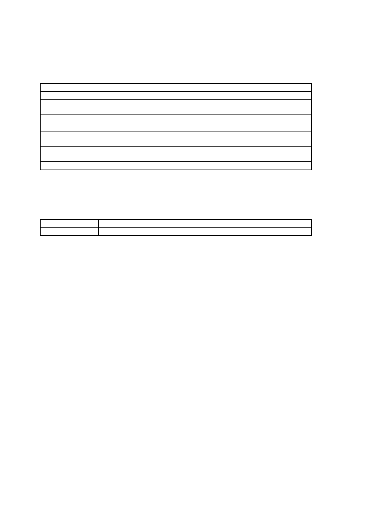
1. Revision History
Date Release Author Description
2005/06/09 0.90 Kimmy Peng First Release
2005/06/13 0.92 Kimmy Peng Revise specification base on the input from
PS review meeting
2005/06/13 0.93 Kimmy Peng Word correction
2005/08/23 0.94 Kevin Yen Spec updating after C2 verification on page 5
2005/10/3 1.00 Kevin Yen Spec updating with output power and power
consumption
2005/11/18 1.10 Kevin Yen Spec updating after C3-2 verification on page
5 to 8.
2005/11/29 1.20 Kevin Yen Spec updating
2. Related Documents
Date Author Document
Y2003 Richard Chou G-660 PS
ZyXEL Communications Corp. Proprietary & Confidential Information
Specifications are subject to change without notice
1

3. Introduction
G-663 is an IEEE 802.11g 54Mbps wireless LAN module. It operates at 2.4GHz unlicensed
frequency band for wireless networks in the home or office environment. Base on the Ti TNETW1350A
chipset. G-663 supports rapid data transfer rate up to 54Mbps and users could work anywhere in the
coverage area and enjoy the convenience and mobility of wireless.
The G-663 also backward compatible with 802.11b access point by using 802.11b standard.
Wireless G-663 also provides a high quality utility, including site survey tool, to allow user easy setting and
maintain wireless networking activities. With built-in IEEE 802.1x client support and dynamic WEP key
exchange features, Wireless G-663 provides best security access.
4. Features
• IEEE 802.11g complies.
• Backward compatible with IEEE 802.11b standard.
• Wire-free access to networked resources from anywhere beyond the desktop.
• Interference resistant designed guarantee reliable performance.
• Delivers data rate up to 54 Mbps.
• Dynamically shifts between 54, 48, 36, 24, 18, 12, 11, 9, 6, 5.5, 2, 1 Mbps network speed, based
on signal strength, for maximum availability and reliability of connection.
• Allows users move between Access Points without resetting their connection reconfiguration.
• Uses 2.4GHz frequency band, which complies with worldwide requirement
• Support WPA2 and AES
• Support WDS, WMM,mSSID,
• Dynamic WEP key exchange support
Remark: * Future support
ZyXEL Communications Corp. Proprietary & Confidential Information
Specifications are subject to change without notice
2

USA (FCC): 2.412GHz~2.462GHz, Europe (CE): 2.412GHz~2.472GHz,
Taiwan (DGT): 2.412GHz~2.462GHz
5. Specification
Specifications
Product Name
Interface
Network Standard
Data Rate
Modulation
Operating Frequency
Operating Channels
Antenna
Receiver Sensitivity
1~11 for N. America, 1~13 for Europe (ETSI), 1~11 channels for Taiwan (DGT)
802.11G WIRELESS LAN MODULE
VLYNQ ( VLYNQ1 CLOCK AS INPUT , VLYNQ2 CLOCK AS OUTPUT )
IEEE802.11g/b COMPLIANT
54Mbps with automatic fallback to 48, 36, 24,18,12,11,9,6,5.5, 2,1 Mbps
802.11g---- 54,48,36,24,18,12,9,6Mbps (OFDM)
802.11b---- CCK (11Mbps, 5.5Mbps), DQPSK (2Mbps), DBPSK (1Mbps)
Default is single antenna, reserve the capability for dual diversity antenna
-96 dBm @ 1M (CCK, 8% PER)
-91 dBm @ 2M (CCK, 8% PER)
-87 dBm @ 5.5M (CCK, 8% PER)
-84 dBm @ 11M (CCK, 8% PER)
-91 dBm @ 6M (OFDM, 10% PER)
-86 dBm @ 9M (OFDM, 10% PER)
-85.6 dBm @ 12M (OFDM, 10% PER)
-83 dBm @ 18M (OFDM, 10% PER)
-81 dBm @ 24M (OFDM, 10% PER)
-77 dBm @ 36M (OFDM, 10% PER)
-74 dBm @ 48M (OFDM, 10% PER)
-72 dBm @ 54M (OFDM, 10% PER)
Current
Consumption
Operational Voltage
Operating
Temperature
Humidity
Dimensions (mm) 59.6 mm x 44.6 mm
ZyXEL Communications Corp. Proprietary & Confidential Information
Specifications are subject to change without notice
TX current consumption: (OFDM) 550 mA @ 20 dBm , 3.3V
(CCK) 550 mA @ 20 dBm , 3.3V
RX current consumption: 260 mA
Co-layout with both 3.3/5V DC (3.3V is default value while 5V is optional)
0 to 50 ℃
10% to 90% Non-condensing
3

g
* Above sheet display with Average output power
Weight (g) 10.2g +/- 0.5g
Calibration Transmit
Output Power
(FCC, 802.11g)
(For calibration in
Production )
Test en
ineer can use following specifications for calibration in
Production .
Typical Ouput Power= Maximum Output power -1.5dB
Minimum Ouput power = Maximum Output power- 3dB
Maximum Output Power (802.11g , FCC)
Channel
Channel 1
Channel 2
Channel 3
Channel 4
Channel 5
Channel 6
Channel 7
Channel 8
Channel 9
6
Mbps9 Mbps
16.5 16.5 16.5 16.5 16.5 16.5 16.3 16
18 18 18 18 18 18 17.8 17.5
19 19 19 19 19 19 18.8 18.5
20 20 20 20 20 20 18.8 18.5
20 20 20 20 20 20 18.8 18.5
20 20 20 20 20 20 18.8 18.5
20 20 20 20 20 20 18.8 18.5
20 20 20 20 20 20 18.8 18.5
19 19 19 19 19 19 18.8 18.5
12
Mbps
18
Mbps
24
Mbps
36
Mbps
48
Mbps
54
Mbps
Channel 10
Channel 11
ZyXEL Communications Corp. Proprietary & Confidential Information
18 18 18 18 18 18 17.8 17.5
16 16 16 16 16 16 15.8 15.5
4
Specifications are subject to change without notice

g
* Above sheet display with Average output power
Calibration Transmit
Output Power
(FCC , 802.11b)
(For calibration in
Production )
Test en
ineer can use following specifications for calibration in
Production .
Typical Ouput Power= Maximum Output power -1.5dB
Minimum Ouput power = Maximum Output power- 3dB
Maximum Output Power
Channel
Mbps2 Mbps
Channel 1
Channel 2
Channel 3
Channel 4
Channel 5
Channel 6
Channel 7
(802.11b , FCC)
1
18 18 18 18
19 19 19 19
19 19 19 19
20 20 20 20
20 20 20 20
20 20 20 20
20 20 20 20
5.5
Mbps
11
Mbps
Channel 8
Channel 9
Channel 10
Channel 11
20 20 20 20
20 20 20 20
18 18 18 18
18 18 18 18
ZyXEL Communications Corp. Proprietary & Confidential Information
Specifications are subject to change without notice
5

We can use FCC Transmit Power Limit Table for 3.3V application to pass
FCC certification
Firmware Engineer must add this table to FCC part of AP code
Test engineer can not use this table for calibration in production
Gain changes (dB) for TX Data Rates
FCC
(802.11b,802.11g)
Transmit Power
Limit Table for 3.3V
application
Channel
Channel 1 -4 -4 -4 -4
Channel 2 0 0 0 0
Channel 3 0 0 0 0
Channel 4 0 0 0 0
Channel 5 0 0 0 0
Channel 6 0 0 0 0
Channel 7 0 0 0 0
Channel 8 0 0 0 0
Channel 9 0 0 0 0
Channel 10 0 0 0 0
Channel 11 -4 -4 -4 -4
6M,9M,
12M
18M,24M,
36M
48M
54M
1M,2M,
5.5M,11M
ZyXEL Communications Corp. Proprietary & Confidential Information
Specifications are subject to change without notice
6

* Above sheet display with Average output power
Firmware engineer can use following specifications to calibrate ETSI
output power with AP
Typical Ouput Power= Maximum Output power -1.5dB
Minimum Ouput power = Maximum Output power- 3dB
Maximum Output Power (802.11g , ETSI)
ETSI
Calibration Transmit
Output Power
(ETSI, 802.11g)
Channel
Channel 1
Channel 2
Channel 3
Channel 4
Channel 5
Channel 6
Channel 7
Channel 8
Channel 9
Channel 10
Channel 11
Channel 12
Channel 13
6
Mbps9 Mbps
16.5 16.5 16.5 16.5 16.5 16.5 16.3 16
17 17 17 17 17 17 16.8 16.5
17 17 17 17 17 17
17 17 17 17 17 17
17 17 17 17 17 17
17 17 17 17 17 17
17 17 17 17 17 17
17 17 17 17 17 17
17 17 17 17 17 17
17 17 17 17 17 17
16 16 16 16 16 16 15.8 15.5
17 17 17 17 17 17
17 17 17 17 17 17
12
Mbps
18
Mbps
24
Mbps
36
Mbps
48
Mbps
16.8 16.5
16.8 16.5
16.8 16.5
16.8 16.5
16.8 16.5
16.8 16.5
16.8 16.5
16.8 16.5
16.8 16.5
16.8 16.5
54
Mbps
ZyXEL Communications Corp. Proprietary & Confidential Information
Specifications are subject to change without notice
7

* Above sheet display with Average output power
Firmware engineer can use following specifications to calibrate ETSI
output power with AP
Typical Ouput Power= Maximum Output power -1.5dB
Minimum Ouput power = Maximum Output power- 3dB
Maximum Output Power
ETSI
Calibration Transmit
Output Power
(ETSI , 802.11b)
Channel
Channel 1
Channel 2
Channel 3
Channel 4
Channel 5
Channel 6
Channel 7
Channel 8
Channel 9
Channel 10
Channel 11
Channel 12
Channel 13
(802.11b , ETSI)
1
Mbps2 Mbps
17 17 17 17
17 17 17 17
17 17 17 17
17 17 17 17
17 17 17 17
17 17 17 17
17 17 17 17
17 17 17 17
17 17 17 17
17 17 17 17
17 17 17 17
17 17 17 17
17 17 17 17
5.5
Mbps
11
Mbps
ZyXEL Communications Corp. Proprietary & Confidential Information
Specifications are subject to change without notice
8

We can use ETSI Transmit Power Limit Table for 3.3V application to pass
FCC certification
Firmware Engineer must add this table to ETSI part of AP code
Test engineer can not use this table for calibration in production
Gain changes (dB) for TX Data Rates
ETSI
(802.11b,802.11g)
Transmit Power
Limit Table for 3.3V
application
Channel
6M,9M,
12M
18M,24M,
36M
48M
54M
1M,2M,
5.5M,11M
Channel 1 0 0 0 -1
Channel 2 -1 -1 -1 -2
Channel 3
Channel 4
Channel 5
Channel 6
Channel 7
Channel 8
Channel 9
-2 -2 -2
-3 -3 -2
-3 -3 -2
-3 -3 -2
-3 -3 -2
-3 -3 -2
-2 -2 -2
-2
-3
-3
-3
-3
-3
-3
Channel 10 -1 -1 -1 -1
Channel 11 0 0 0 -1
Channel 12 -3 -3 -2 -3
Channel 13 -3 -3 -2 -3
ZyXEL Communications Corp. Proprietary & Confidential Information
9
Specifications are subject to change without notice

FCC Statement
Warning: Changes or modificatio ns to this unit not expressly approved by th e party responsible for
compliance could void the user authority to operate the equipment.
This device complies with Part 15 of the FCC Rules. Operation is subject to the following
twoconditions:
(1) this device may not cause harmful interference, and
(2) this device must accept any interference received, including interference that may cause undesired
operation.
NOTE:
device, pursuant to Part 15 of the FCC Rules. These limits are designed to provide reasonable
protection against harmful interference in a residential installation. This equipment generates, uses
and can radiate radio frequency energy and, if not installed and used in accordance with the
instructions, may cause harmful interference to r adio co mmun ication s. Howev er, there i s no g uarantee
that interference will not occur in a particular installation. If this equipment does cause harmful
interference to radio or television reception, which can be determin ed by turning the equipment off
and on, the user is encouraged to try to correct the interference by one or more of the following
measures:
Reorient or relocate the receiving antenna. Increase the separation between the equipment and
receiver. Connect the equipment into an outlet on a circuit d ifferent from that to which the receiver is
needed. Consult the dealer or an experienced radio/ TV technician for help.
Service Center in U.S.A
Company Name : ZyXEL Communications, INC. USA
Company Address: 1650 E. Miraloma Ave. Placentia, CA 92870
Tel: (714)632-0858
This equipment has been tested and found to comply with the limits for a Class B digital
CAUTION:
1. To comply with FCC RF exposure compliance requirements, a separation di stance of at lea st 20 cm
must be maintained between the antenna of this device and all persons.
2. This Transmitter must not be co-located or operating in conjunction with any other antenna or
transmitter
This device is intended only for OEM integrators under the following conditions:
1) The antenna must be installed su ch that 20 cm is maintained b etween the antenna and users. For
ZyXEL Communications Corp. Proprietary & Confidential Information
Specifications are subject to change without notice

laptop installations, the antenna must be installed to ensure that the proper spacing is maintained in the
event the users places the device in their lap duri ng use (i.e. posi tioning of antennas must b e placed in
the upper portion of the LCD panel only to ensure 20 cm will be maintained if the user places the
device in their lap for use) and
2) The transmitter module may not be co-located with any other transmitter or antenna. As long as the
2 conditions above are met, further transmitter testing will not be required. However, the OEM
integrator is still responsible for testing their end-product for any additional compliance requirements
required with this module installed (for example, digital device emissions, PCperipheral requirements,
etc.).
IMPORTANT NOTE: In the event that these conditions can not be met (for example certain
laptop configurations or co-location with another transmitter), then the FCC authorization is no longer
considered valid and the FCC ID can not be used on the final product. In these
circumstances, the OEM integrator will be responsible for re-evaluating the end product (including the
transmitter) and obtaining a separate FCC authorization.
End Product Labeling
This transmitter module is authorized on ly for use i n devices where the ant enna may be installed suc h
that 20 cm may be maintained between the antenna and users (for example access points, routers,
wireless ASDL modems, certain laptop configurations, and similar equipment). The final end product
must be labeled in a visible area with the following: "Contains TX FCC ID: I88G663".
RF Exposure Manual Information That Must be Included
The users manual for end users must include the following information in a prominent location
"IMPORTANT NOTE: To comply with FCC RF exposure compliance requirements, the antenna used
for this transmitter must be installed to provide a separation distance of at least 20 cm from all persons
and must not be co-located or operating in conjunction with any other antenna or transmitter."
Additional Information That Must be Provided to OEM Integrators
The end user should NOT be provided any instructions on how to remove or install the device.
注意 !
依據 低功率電波輻射性電機管理辦法
第十二條 經型式認證合格之低功率射頻電機,非經許可,公司、商號或使用
者均不得擅自變更頻率、加大功率或變更原設計之特性及功能。
第十四條 低功率射頻電機之使用不得影響飛航安全及干擾合法通信;經發現
有干擾現象時,應立即停用,並改善至無干擾時方得繼續使用。
前項合法通信,指依電信規定作業之無線電信。低功率射頻電機須忍
受合法通信或工業、科學及醫療用電波輻射性電機設備之干擾。
ZyXEL Communications Corp. Proprietary & Confidential Information
Specifications are subject to change without notice
 Loading...