

Page 1

ZyAIR B-420
Wireless LAN Ethernet Adapter and Bridge
User's Guide
Version 3.50
September 2003
Page 2

ZyAIR B-420 Wireless LAN Ethernet Adapter and Bridge
Copyright
Copyright © 2003 by ZyXEL Communications Corporation.
The contents of this publication may not be reproduced in any part or as a whole, transcribed, stored in a
retrieval system, translated into any language, or transmitted in any form or by any means, electronic,
mechanical, magnetic, optical, chemical, photocopying, manual, or otherwise, without the prior written
permission of ZyXEL Communications Corporation.
Published by ZyXEL Communications Corporation. All rights reserved.
Disclaimer
ZyXEL does not assume any liability arising out of the application or use of any products, or software
described herein. Neither does it convey any license under its patent rights nor the patent rights of others.
ZyXEL further reserves the right to make changes in any products described herein without notice. This
publication is subject to change without notice.
Trademarks
ZyNOS (ZyXEL Network Operating System) is a registered trademark of ZyXEL Communications, Inc.
Other trademarks mentioned in this publication are used for identification purposes only and may be
properties of their respective owners.
ii Copyright
Page 3

ZyAIR B-420 Wireless LAN Ethernet Adapter and Bridge
Federal Communications Commission
(FCC) Interference Statement
This device complies with Part 15 of FCC rules. Operation is subject to the following two conditions:
• This device may not cause harmful interference.
• This device must accept any interference received, including interference that may cause undesired
operations.
This equipment has been tested and found to comply with the limits for a Class B digital device pursuant to
Part 15 of the FCC Rules. These limits are designed to provide reasonable protection against harmful
interference in a commercial environment. This equipment generates, uses, and can radiate radio frequency
energy, and if not installed and used in accordance with the instructions, may cause harmful interference to
radio communications.
If this equipment does cause harmful interference to radio/television reception, which can be determined by
turning the equipment off and on, the user is encouraged to try to correct the interference by one or more of
the following measures:
1. Reorient or relocate the receiving antenna.
2. Increase the separation between the equipment and the receiver.
3. Connect the equipment into an outlet on a circuit different from that to which the receiver is connected.
4. Consult the dealer or an experienced radio/TV technician for help.
Notice 1
Changes or modifications not expressly approved by the party responsible for compliance could void the
user's authority to operate the equipment.
Certifications
Refer to the product page at www.zyxel.com
FCC Statement iii
.
Page 4

ZyAIR B-420 Wireless LAN Ethernet Adapter and Bridge
ZyXEL Limited Warranty
ZyXEL warrants to the original end user (purchaser) that this product is free from any defects in materials
or workmanship for a period of up to two years from the date of purchase. During the warranty period, and
upon proof of purchase, should the product have indications of failure due to faulty workmanship and/or
materials, ZyXEL will, at its discretion, repair or replace the defective products or components without
charge for either parts or labor, and to whatever extent it shall deem necessary to restore the product or
components to proper operating condition. Any replacement will consist of a new or re-manufactured
functionally equivalent product of equal value, and will be solely at the discretion of ZyXEL. This warranty
shall not apply if the product is modified, misused, tampered with, damaged by an act of God, or subjected
to abnormal working conditions.
Note
Repair or replacement, as provided under this warranty, is the exclusive remedy of the purchaser. This
warranty is in lieu of all other warranties, express or implied, including any implied warranty of
merchantability or fitness for a particular use or purpose. ZyXEL shall in no event be held liable for indirect
or consequential damages of any kind of character to the purchaser.
To obtain the services of this warranty, contact ZyXEL's Service Center for your Return Material
Authorization number (RMA). Products must be returned Postage Prepaid. It is recommended that the unit
be insured when shipped. Any returned products without proof of purchase or those with an out-dated
warranty will be repaired or replaced (at the discretion of ZyXEL) and the customer will be billed for parts
and labor. All repaired or replaced products will be shipped by ZyXEL to the corresponding return address,
Postage Paid. This warranty gives you specific legal rights, and you may also have other rights that vary
from country to country.
Safety Warnings
1. To reduce the risk of fire, use only No. 26 AWG or larger telephone wire.
2. Do not use this product near water, for example, in a wet basement or near a swimming pool.
3. Avoid using this product during an electrical storm. There may be a remote risk of electric shock from
lightening.
iv ZyXEL Warranty
Page 5

ZyAIR B-420 Wireless LAN Ethernet Adapter and Bridge
Customer Support
Please have the following information ready when you contact customer support.
• Product model and serial number.
• Warranty Information.
• Date that you received your device.
• Brief description of the problem and the steps you took to solve it.
METHOD
LOCATION
WORLDWIDE
AMERICA
E-MAIL
SUPPORT/SALES
support@zyxel.com.tw
sales@zyxel.com.tw
support@zyxel.com +1-800-255-4101 www.us.zyxel.com NORTH
sales@zyxel.com
support@zyxel.dk +45-3955-0700 www.zyxel.dk SCANDINAVIA
sales@zyxel.dk
support@zyxel.de +49-2405-6909-0 www.zyxel.de GERMANY
sales@zyxel.de
+886-3-578-2439 ftp.europe.zyxel.com
+1-714-632-0858 ftp.zyxel.com
+45-3955-0707 ftp.zyxel.dk
+49-2405-6909-99
TELEPHONE/FAX WEB SITE/ FTP SITE REGULAR MAIL
+886-3-578-3942 www.zyxel.com
www.europe.zyxel.com
ZyXEL Communications Corp.,
6 Innovation Road II, ScienceBased Industrial Park, Hsinchu
300, Taiwan.
ZyXEL Communications A/S,
Columbusvej 5, 2860 Soeborg,
Denmark.
ZyXEL Deutschland GmbH.
Adenauerstr. 20/A2 D-52146
Wuerselen, Germany
Customer Support v
Page 6

ZyAIR B-420 Wireless LAN Ethernet Adapter and Bridge
Table of Contents
Copyright......................................................................................................................................................... ii
Federal Communications Commission (FCC) Interference Statement.....................................................iii
ZyXEL Limited Warranty ............................................................................................................................iv
Customer Support........................................................................................................................................... v
List of Figures ................................................................................................................................................ix
List of Tables ................................................................................................................................................. xii
Preface ..........................................................................................................................................................xiii
OVERVIEW.....................................................................................................................................................I
Chapter 1 Getting to Know Your ZyAIR................................................................................................... 1-1
1.1 Introducing the ZyAIR............................................................................................................... 1-1
1.2 ZyAIR Features..........................................................................................................................1-1
1.3 Applications for the ZyAIR .......................................................................................................1-4
1.3.1 Infrastructure......................................................................................................................1-4
1.3.2 Ad Hoc...............................................................................................................................1-5
1.3.3 Bridge ................................................................................................................................1-5
Chapter 2 Introducing the Web Configurator ..........................................................................................2-1
2.1 Accessing the ZyAIR Web Configurator...................................................................................2-1
2.2 Navigating the ZyAIR Web Configurator..................................................................................2-2
2.3 Resetting the ZyAIR ..................................................................................................................2-3
2.3.1 Method of Restoring Factory-Defaults ..............................................................................2-3
SYSTEM, WIRELESS AND IP.................................................................................................................... II
Chapter 3 System Screens ........................................................................................................................... 3-1
3.1 System Overview.......................................................................................................................3-1
3.2 Configuring General Setup ........................................................................................................3-1
3.3 Configuring Password................................................................................................................3-2
3.4 Configuring Time Setting ..........................................................................................................3-3
Chapter 4 Wireless LAN .............................................................................................................................4-1
4.1 Wireless LAN Basis................................................................................................................... 4-1
4.1.1 Channel .............................................................................................................................. 4-1
4.1.2 ESS ID ...............................................................................................................................4-1
4.1.3 WEP Encryption ................................................................................................................4-1
4.1.4 RTS/CTS............................................................................................................................4-1
4.1.5 Fragmentation Threshold................................................................................................... 4-3
4.2 Wireless Security Overview.......................................................................................................4-3
4.3 WEP Overview ..........................................................................................................................4-3
4.3.1 Data Encryption .................................................................................................................4-4
4.3.2 Authentication.................................................................................................................... 4-4
4.4 Configuring Wireless ................................................................................................................. 4-5
4.4.1 Infrastructure......................................................................................................................4-5
vi Table of Contents
Page 7

ZyAIR B-420 Wireless LAN Ethernet Adapter and Bridge
4.4.2 Ad-Hoc...............................................................................................................................4-8
4.4.3 Bridge...............................................................................................................................4-10
Chapter 5 IP Screen .....................................................................................................................................5-1
5.1 Factory Ethernet Defaults...........................................................................................................5-1
5.2 TCP/IP Parameters .....................................................................................................................5-1
5.2.1 IP Address and Subnet Mask..............................................................................................5-1
5.3 Configuring IP............................................................................................................................5-2
LOGS ............................................................................................................................................................ III
Chapter 6 Logs Screens ...............................................................................................................................6-1
6.1 Configuring View Log ...............................................................................................................6-1
6.2 Configuring Log Settings ...........................................................................................................6-2
MAINTENANCE......................................................................................................................................... IV
Chapter 7 Maintenance ...............................................................................................................................7-1
7.1 Maintenance Overview ..............................................................................................................7-1
7.2 System Status Screen .................................................................................................................7-1
7.2.1 System Statistics.................................................................................................................7-2
7.3 Wireless Screen..........................................................................................................................7-3
7.4 F/W Upload Screen ....................................................................................................................7-5
7.5 Configuration Screen .................................................................................................................7-7
7.5.1 Backup Configuration ........................................................................................................7-7
7.5.2 Restore Configuration ........................................................................................................7-8
7.5.3 Back to Factory Defaults..................................................................................................7-10
SMT CONFIGURATION.............................................................................................................................. V
Chapter 8 Introducing the SMT .................................................................................................................8-1
8.1 Connect to your ZyAIR Using Telnet ........................................................................................8-1
8.2 Changing the System Password .................................................................................................8-1
8.3 ZyAIR SMT Menu Overview Example .....................................................................................8-2
8.4 Navigating the SMT Interface....................................................................................................8-4
8.4.1 System Management Terminal Interface Summary...........................................................8-5
Chapter 9 General Setup.............................................................................................................................9-1
9.1 General Setup.............................................................................................................................9-1
9.1.1 Procedure To Configure Menu 1........................................................................................9-1
Chapter 10 LAN Setup ..............................................................................................................................10-1
10.1 LAN Setup ...............................................................................................................................10-1
10.2 TCP/IP Ethernet Setup .............................................................................................................10-1
10.3 Wireless LAN Setup ................................................................................................................10-2
10.3.1 Configuring Bridge Link..................................................................................................10-5
Chapter 11 SNMP Configuration..............................................................................................................11-1
11.1 About SNMP............................................................................................................................11-1
11.2 Supported MIBs .......................................................................................................................11-2
11.3 SNMP Configuration ...............................................................................................................11-2
Table of Contents vii
Page 8

ZyAIR B-420 Wireless LAN Ethernet Adapter and Bridge
11.4 SNMP Traps ............................................................................................................................11-3
Chapter 12 System Information ...............................................................................................................12-1
12.1 System Status...........................................................................................................................12-1
12.2 System Information..................................................................................................................12-3
12.2.1 System Information..........................................................................................................12-3
12.2.2 Console Port Speed.......................................................................................................... 12-4
12.3 Log and Trace ..........................................................................................................................12-5
12.3.1 Viewing Error Log........................................................................................................... 12-5
Chapter 13 Firmware and Configuration File Maintenance .................................................................13-1
13.1 Filename Conventions .............................................................................................................13-1
13.2 Backup Configuration.............................................................................................................. 13-2
13.2.1 Backup Configuration Using FTP....................................................................................13-2
13.2.2 Using the FTP command from the DOS Prompt .............................................................13-3
13.2.3 Backup Configuration Using TFTP ................................................................................. 13-4
13.2.4 Example: TFTP Command ..............................................................................................13-4
13.3 Restore Configuration.............................................................................................................. 13-5
13.4 Uploading Firmware and Configuration Files .........................................................................13-6
13.4.1 Firmware Upload ............................................................................................................. 13-7
13.4.2 Configuration File Upload ............................................................................................... 13-7
13.4.3 Using the FTP command from the DOS Prompt Example ..............................................13-8
13.4.4 TFTP File Upload ............................................................................................................13-9
13.4.5 Example: TFTP Command ............................................................................................13-10
Chapter 14 System Maintenance and Information.................................................................................14-1
14.1 Command Interpreter Mode.....................................................................................................14-1
14.2 Time and Date Setting .............................................................................................................14-2
APPENDICES...............................................................................................................................................VI
Appendix A Troubleshooting...................................................................................................................... A-1
Appendix B Brute-Force Password Guessing Protection........................................................................ B-1
Appendix C Setting up Your Computer’s IP Address.............................................................................. C-1
Appendix D Wireless LAN and IEEE 802.11 ...........................................................................................D-1
Appendix E Antenna Selection and Positioning Recommendation ........................................................ E-1
Appendix F Power over Ethernet Specifications...................................................................................... F-1
Appendix G IP Subnetting .........................................................................................................................G-1
Appendix H Command Interpreter...........................................................................................................H-1
Appendix I Log Descriptions ...................................................................................................................... I-1
Appendix J Power Adaptor Specifications ................................................................................................J-1
Appendix K Index.......................................................................................................................................K-1
viii Table of Contents
Page 9

ZyAIR B-420 Wireless LAN Ethernet Adapter and Bridge
List of Figures
Figure 1-1 PoE Installation Example ............................................................................................................. 1-2
Figure 1-2 Infrastructure Network Example .................................................................................................. 1-4
Figure 1-3 Ad-hoc Application Example ....................................................................................................... 1-5
Figure 1-4 Bridge Application Example ........................................................................................................ 1-5
Figure 2-1 Web Browser Address Field ......................................................................................................... 2-1
Figure 2-2 Change Password Screen.............................................................................................................. 2-1
Figure 2-3 The MAIN MENU Screen of the Web Configurator.................................................................... 2-2
Figure 3-1 System General Setup .................................................................................................................. 3-1
Figure 3-2 Password....................................................................................................................................... 3-3
Figure 3-3 Time Setting ................................................................................................................................. 3-4
Figure 4-1 RTS/CTS ...................................................................................................................................... 4-2
Figure 4-2 ZyAIR Wireless Security Levels .................................................................................................. 4-3
Figure 4-3 WEP Authentication Steps............................................................................................................ 4-4
Figure 4-4 Infrastructure Network Example .................................................................................................. 4-5
Figure 4-5 Roaming Example........................................................................................................................ 4-6
Figure 4-6 Wireless : Infrastructure ............................................................................................................... 4-7
Figure 4-7 Ad-hoc (IBSS) Wireless LAN ...................................................................................................... 4-9
Figure 4-8 Wireless : Ad Hoc......................................................................................................................... 4-9
Figure 4-9 Bridging Example....................................................................................................................... 4-10
Figure 4-10 Bridge Loop: Two Bridges Connected to Hub ..........................................................................4-11
Figure 4-11 Bridge Loop: Bridge Connected to Wired LAN........................................................................4-11
Figure 4-12 Wireless : Bridge ...................................................................................................................... 4-12
Figure 5-1 IP .................................................................................................................................................. 5-2
Figure 6-1 View Log ...................................................................................................................................... 6-1
Figure 6-2 Log Settings.................................................................................................................................. 6-3
Figure 7-1 System Status ............................................................................................................................... 7-1
Figure 7-2 System Status: Show Statistics ..................................................................................................... 7-2
Figure 7-3 Channel Usage.............................................................................................................................. 7-4
Figure 7-4 Firmware Upload.......................................................................................................................... 7-5
Figure 7-5 Firmware Upload In Process ........................................................................................................ 7-6
Figure 7-6 Network Temporarily Disconnected............................................................................................. 7-7
Figure 7-7 Firmware Upload Error ................................................................................................................ 7-7
Figure 7-8 Backup Configuration .................................................................................................................. 7-8
Figure 7-9 Restore Configuration .................................................................................................................. 7-8
Figure 7-10 Configuration Upload Successful............................................................................................... 7-9
Figure 7-11 Network Temporarily Disconnected........................................................................................... 7-9
Figure 7-12 Configuration Upload Error ..................................................................................................... 7-10
Figure 7-13 Back to Factory Default............................................................................................................ 7-10
Figure 7-14 Reset Warning Message.............................................................................................................7-11
List of Figures ix
Page 10

ZyAIR B-420 Wireless LAN Ethernet Adapter and Bridge
Figure 8-1 Login Screen .................................................................................................................................8-1
Figure 8-2 Menu 23.1 System Security : Change Password...........................................................................8-2
Figure 8-3 ZyAIR B-420 SMT Menu Overview Example .............................................................................8-3
Figure 8-4 ZyAIR B-420 SMT Main Menu....................................................................................................8-5
Figure 9-1 Menu 1 General Setup...................................................................................................................9-1
Figure 10-1 Menu 3 LAN Setup...................................................................................................................10-1
Figure 10-2 Menu 3.2 TCP/IP Setup.............................................................................................................10-1
Figure 10-3 Menu 3.5 Wireless LAN Setup .................................................................................................10-3
Figure 10-4 Menu 3.5 Wireless LAN Setup .................................................................................................10-5
Figure 10-5 Menu 3.5.4 Bridge Link Configuration.....................................................................................10-5
Figure 11-1 SNMP Management Model....................................................................................................... 11-1
Figure 11-2 Menu 22 SNMP Configuration .................................................................................................11-3
Figure 12-1 Menu 24 System Maintenance..................................................................................................12-1
Figure 12-2 Menu 24.1 System Maintenance : Status ..................................................................................12-2
Figure 12-3 Menu 24.2 System Information and Console Port Speed..........................................................12-3
Figure 12-4 Menu 24.2.1 System Information : Information........................................................................12-3
Figure 12-5 Menu 24.2.2 System Maintenance : Change Console Port Speed.............................................12-4
Figure 12-6 Menu 24.3 System Maintenance : Log and Trace.....................................................................12-5
Figure 12-7 Sample Error and Information Messages..................................................................................12-5
Figure 13-1 Menu 24.5 Backup Configuration.............................................................................................13-2
Figure 13-2 FTP Session Example................................................................................................................13-3
Figure 13-3 Menu 24.6 Restore Configuration.............................................................................................13-6
Figure 13-4 Menu 24.7 System Maintenance : Upload Firmware................................................................13-6
Figure 13-5 Menu 24.7.1 System Maintenance : Upload System Firmware ................................................13-7
Figure 13-6 Menu 24.7.2 System Maintenance : Upload System Configuration File ..................................13-8
Figure 13-7 FTP Session Example................................................................................................................13-9
Figure 14-1 Menu 24 System Maintenance..................................................................................................14-1
Figure 14-2 Valid CI Commands .................................................................................................................. 14-1
Figure 14-3 Menu 24.10 System Maintenance : Time and Date Setting ......................................................14-2
x List of Figures
Page 11

Page 12

ZyAIR B-420 Wireless LAN Ethernet Adapter and Bridge
List of Tables
Table 3-1 System General Setup.....................................................................................................................3-2
Table 3-2 Password.........................................................................................................................................3-3
Table 3-3 Time Setting....................................................................................................................................3-4
Table 4-1 Wireless : Infrastructure..................................................................................................................4-7
Table 4-2 Wireless : Ad Hoc .........................................................................................................................4-10
Table 4-3 Wireless : Bridge...........................................................................................................................4-12
Table 5-1 Private IP Address Ranges..............................................................................................................5-2
Table 5-2 IP.....................................................................................................................................................5-3
Table 6-1 View Log ........................................................................................................................................6-2
Table 6-2 Log Settings....................................................................................................................................6-3
Table 7-1 System Status..................................................................................................................................7-1
Table 7-2 System Status: Show Statistics .......................................................................................................7-2
Table 7-3 Channel Usage................................................................................................................................7-4
Table 7-4 Firmware Upload............................................................................................................................7-6
Table 7-5 Restore Configuration.....................................................................................................................7-9
Table 8-1 Main Menu Commands ..................................................................................................................8-4
Table 8-2 Main Menu Summary.....................................................................................................................8-5
Table 9-1 Menu 1 General Setup ....................................................................................................................9-2
Table 10-1 Menu 3.2 TCP/IP Setup .............................................................................................................. 10-2
Table 10-2 Menu 3.5 Wireless LAN Setup ...................................................................................................10-3
Table 10-3 Menu 3.5.4 Bridge Link Configuration ......................................................................................10-6
Table 11-1 Menu 22 SNMP Configuration ...................................................................................................11-3
Table 11-2 SNMP Traps................................................................................................................................11-4
Table 11-3 Ports and Interface Types............................................................................................................ 11-4
Table 12-1 Menu 24.1 System Maintenance : Status.................................................................................... 12-2
Table 12-2 System Maintenance : Information............................................................................................. 12-4
Table 13-1 Filename Conventions ................................................................................................................13-2
Table 13-2 General Commands for Third Party FTP Clients........................................................................13-3
Table 13-3 General Commands for Third Party TFTP Clients .....................................................................13-5
Table 14-1 Menu 24.10 System Maintenance : Time and Date Setting........................................................14-2
xii List of Tables
Page 13

ZyAIR B-420 Wireless LAN Ethernet Adapter and Bridge
Preface
Congratulations on your purchase of the ZyAIR B-420 Wireless LAN Ethernet Adapter and Bridge.
The ZyAIR B-420 is an IEEE 802.11b compliant 11Mbps wireless LAN Ethernet Adapter and Bridge, which
supports Wireless Distribution System (WDS) for workgroup bridge applications.
This User’s Guide is designed to guide you through the configuration of your ZyAIR using the web
configurator or the SMT.
Use the web configurator, System Management Terminal (SMT) or command
interpreter interface to configure your ZyAIR. Not all features can be configured
through all interfaces.
The web configurator parts of this guide contain background information on features configurable by the web
configurator and the SMT. The SMT parts of this guide contain background information on features not
configurable by the web configurator.
Related Documentation
Supporting Disk
Refer to the included CD for support documents.
Quick Installation Guide
Our Quick Installation Guide is designed to help you get up and running right away. It contains
information on the configuration of key features and hardware connections and installation.
ZyXEL Web Site
The ZyXEL download library at www.zyxel.com
also refer to www.zyxel.com
for an online glossary of networking terms.
contains additional support documentation. Please
Syntax Conventions
• “Type” means for you to type one or more characters and press the carriage return. “Select” or “Choose”
means for you to use one predefined choices.
• Enter, or carriage return, key; [ESC] means the escape key and [SPACE BAR] means the space bar.
[UP] and [DOWN] are the up and down arrow keys.
• Mouse action sequences are denoted using a comma. For example, “click the Apple icon, Control
Panels and then Modem” means first click the Apple icon, then point your mouse pointer to Control
Panels and then click Modem.
• For brevity’s sake, we will use “e.g.,” as a shorthand for “for instance”, and “i.e.,” for “that is” or “in
other words” throughout this manual.
Preface xiii
Page 14

ZyAIR B-420 Wireless LAN Ethernet Adapter and Bridge
• The ZyAIR B-420 Wireless LAN Ethernet Adapter and Bridge will be referred to simply as the ZyAIR
in the user’s guide.
User Guide Feedback
Help us help you. E-mail all User Guide-related comments, questions or suggestions for improvement to
techwriters@zyxel.com.tw or send regular mail to The Technical Writing Team, ZyXEL Communications
Corp., 6 Innovation Road II, Science-Based Industrial Park, Hsinchu, 300, Taiwan. Thank you.
xiv Preface
Page 15

Overview
PPaarrtt II::
OVERVIEW
This part introduces the main features and applications of the ZyAIR and shows how to access the web configurator.
I
Page 16

Page 17

ZyAIR B-420 Wireless LAN Ethernet Adapter and Bridge
Chapter 1
Getting to Know Your ZyAIR
This chapter introduces the main features and applications of the ZyAIR.
1.1 Introducing the ZyAIR
The ZyAIR is an IEEE802.11b compliant 11Mbps wireless LAN Ethernet Adapter and Bridge. The ZyAIR
provides easy network access to mobile users. The ZyAIR also supports Wireless Distribution System
(WDS) for workgroup bridge applications.
You may configure and manage the ZyAIR using SMT via Telnet, embedded web configurator or SNMP.
You can access the SMT or web configurator from the LAN only in Infrastructure and Ad-Hoc modes. But in
WDS mode, the ZyAIR is configurable from either end of the bridge link.
1.2 ZyAIR Features
Your ZyAIR is packed with a number of features that give it the flexibility to provide a complete networking
solution for almost any user.
10/100M Auto-negotiating Ethernet/Fast Ethernet Interface
This auto-negotiating feature allows the ZyAIR to detect the speed of incoming transmissions and adjust
appropriately without manual intervention. It allows data transfer of either 10 Mbps or 100 Mbps in either
half-duplex or full-duplex mode depending on your Ethernet network.
10/100M Auto-crossover Ethernet/Fast Ethernet Interface
The LAN interface automatically adjusts to either a crossover or straight-through Ethernet cable.
Reset Button
The ZyAIR reset button is built into the top panel. Use this button to restore the factory default password to
1234; IP address to 192.168.1.11, subnet mask to 255.255.255.0.
ZyAIR LED
The blue ZyAIR LED (also known as the Breathing LED) is on when the ZyAIR is on and blinks (or breaths)
when data is being transmitted to/from its wireless stations. You may use the web configurator to turn this
LED off even when the ZyAIR is on and data is being transmitted/received.
Getting to Know Your ZyAIR 1-1
Page 18
ZyAIR B-420 Wireless LAN Ethernet Adapter and Bridge
Bridge
A Bridge link LED turns steady on green when your ZyAIR acts as a bridge, establishing a wireless link to
another AP.
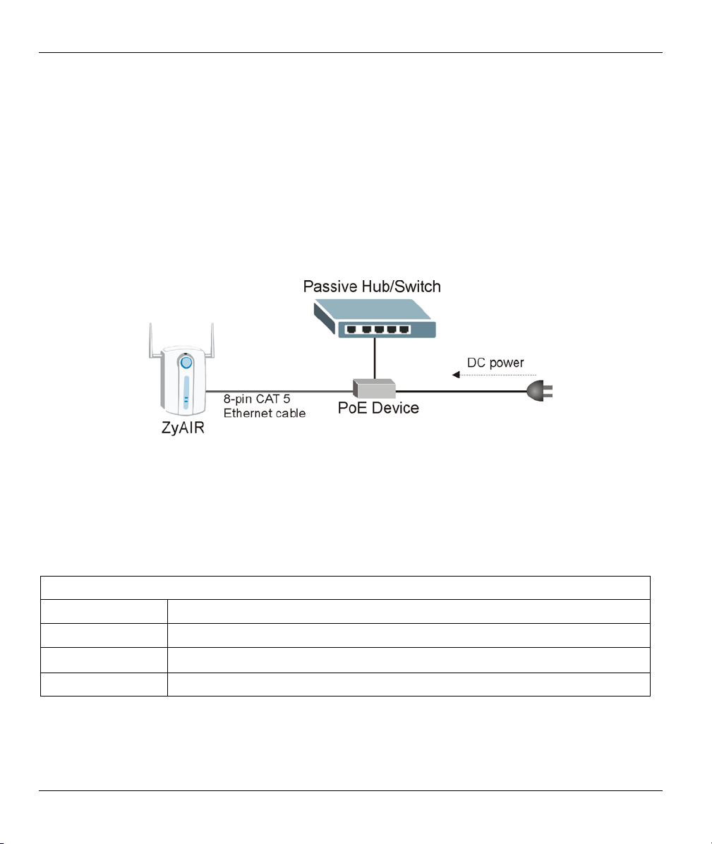
Power over Ethernet (PoE)
Power over Ethernet (PoE) is the ability to provide power to your ZyAIR via an 8-pin CAT 5 Ethernet cable,
eliminating the need for a nearby power source. An injector or PoE device (not included) is also needed to
supply the Ethernet cable with power. This feature allows increased flexibility in the locating of your ZyAIR.
You only need to connect the external power adaptor if you are not using PoE. If you simultaneously use
both PoE and the external power adaptor, the ZyAIR will draw power from the PoE connection only. Refer
to the appendix for more information about PoE.
Figure 1-1 PoE Installation Example
802.11b Wireless LAN Standard
ZyAIR products containing the letter “B” in the model name, such as ZyAIR B-1000, ZyAIR B-1020,
comply with the 802.11b wireless standard.
The 802.11b data rate and corresponding modulation techniques are as follows. The modulation technique
defines how bits are encoded onto radio waves.
802.11b
Data Rate (Mbps) Modulation
1 DBPSK (Differential Binary Phase Shift Keyed)
2
5.5 / 11 CCK (Complementary Code Keying)
DQPSK (Differential Quadrature Phase Shift Keying
1-2 Getting to Know Your ZyAIR
)
Page 19

ZyAIR B-420 Wireless LAN Ethernet Adapter and Bridge
The ZyAIR may be prone to RF (Radio Frequency) interference from other 2.4 GHz
devices such as microwave ovens, wireless phones, Bluetooth enabled devices,
and other wireless LANs.
Output Power Management
Power Management is the ability to set the level of output power. This feature is only available in bridge
mode.
There may be interference or difficulty with channel assignment when there is a high density of APs within a
coverage area. In this case you can lower the output power of each access point, thus enabling you to place
access points closer together.
WDS Functionality
A Distribution System (DS) is a wired connection between two or more APs, while a Wireless Distribution
System (WDS) is a wireless connection. Your ZyAIR supports WDS, providing a cost-effective solution for
wireless network expansion.
Brute-Force Password Guessing Protection
The ZyAIR has a special protection mechanism to discourage brute-force password guessing attacks on the
ZyAIR's management interfaces. You can specify a wait-time that must expire before entering a fourth
password after three incorrect passwords have been entered. Please see the appendix for details about this
feature.
SNMP
SNMP (Simple Network Management Protocol) is a protocol used for exchanging management information
between network devices. SNMP is a member of the TCP/IP protocol suite. Your ZyAIR supports SNMP
agent functionality, which allows a manger station to manage and monitor the ZyAIR through the network.
The ZyAIR supports SNMP version one (SNMPv1) and version two c (SNMPv2c).
Full Network Management
The embedded web configurator is an all-platform web-based utility that allows you to easily access the
ZyAIR’s management settings. Most functions of the ZyAIR are also software configurable via the SMT
(System Management Terminal) interface. The SMT is a menu-driven interface that you can access from a
terminal emulator over a telnet connection.
Logging and Tracing
♦ Built-in message logging and packet tracing.
♦ Unix syslog facility support.
Getting to Know Your ZyAIR 1-3
Page 20
ZyAIR B-420 Wireless LAN Ethernet Adapter and Bridge
Embedded FTP and TFTP Servers
The ZyAIR’s embedded FTP and TFTP servers enable fast firmware upgrades as well as configuration file
backups and restoration.
Wireless LAN Channel Usage
The Wireless Channel Usage screen displays whether the radio channels are used by other wireless devices
within the transmission range of the ZyAIR. This allows you to select the channel with minimum interference
for your ZyAIR.
1.3 Applications for the ZyAIR
Here are some application examples of what you can do with your ZyAIR.
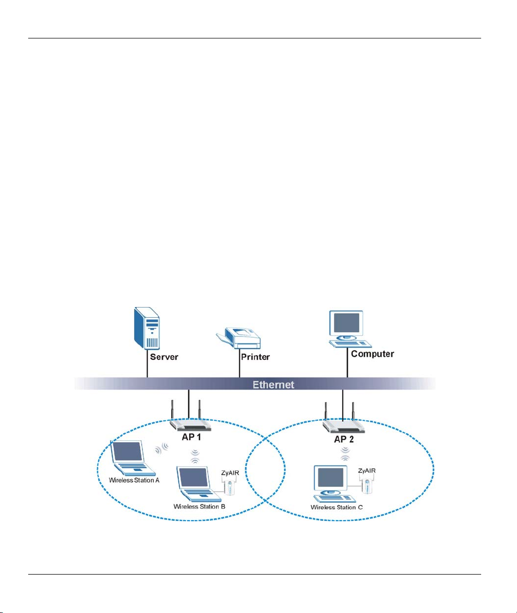
1.3.1 Infrastructure
When wireless stations wish to access and share resources on the wired network, they should use
infrastructure mode. Wireless stations may move from one coverage area to another seamlessly without
network interruption. This is called roaming.
The figure below depicts an infrastructure network example.
Figure 1-2 Infrastructure Network Example
1-4 Getting to Know Your ZyAIR
Page 21
ZyAIR B-420 Wireless LAN Ethernet Adapter and Bridge
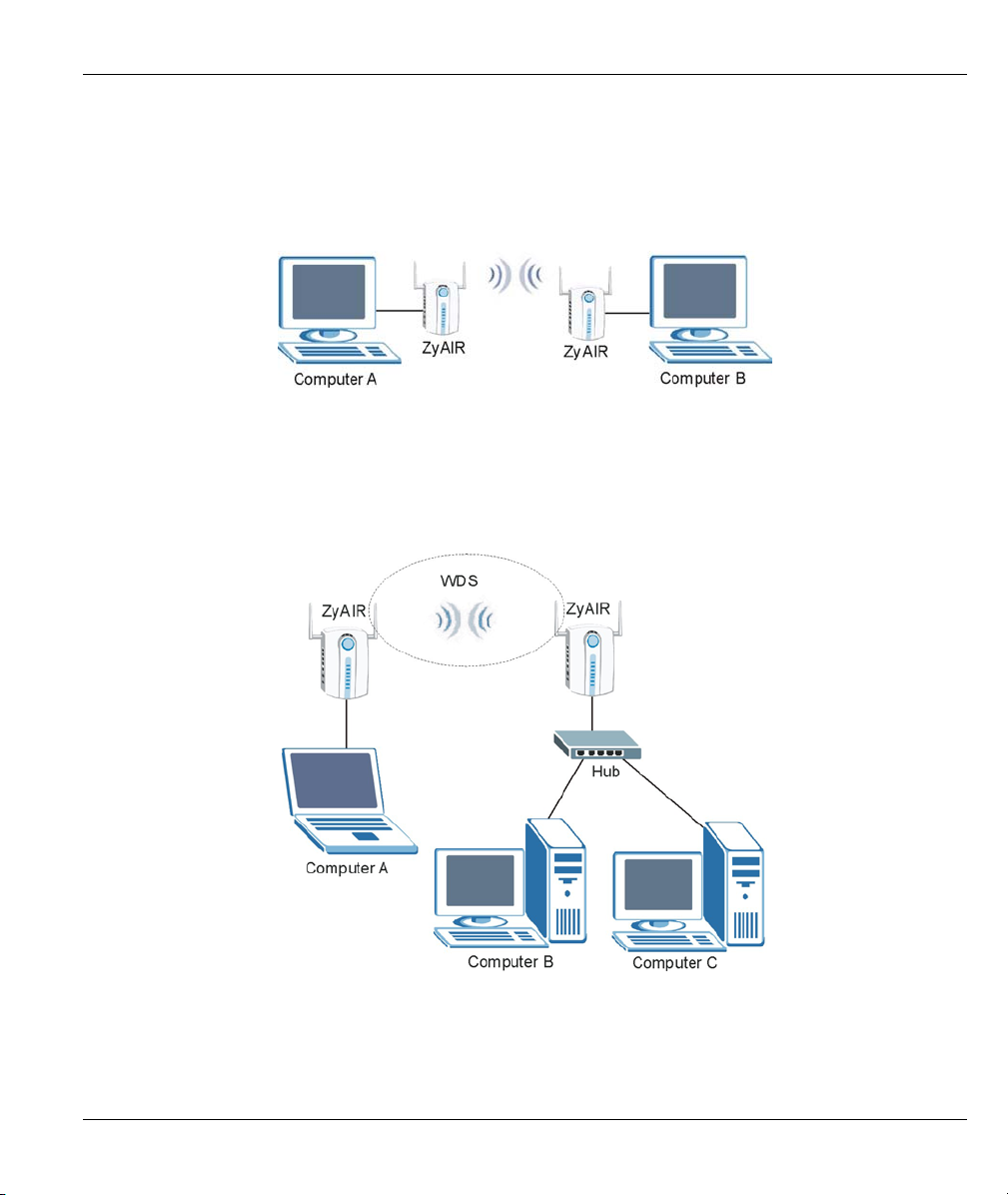
1.3.2 Ad Hoc
An ad-hoc network consists of two or more computers communicating with one another through the wireless
network. No access points (APs) or existing wired networks are needed. An access point acts as a bridge
between the wireless and wired networks.
Figure 1-3 Ad-hoc Application Example
1.3.3 Bridge
The ZyAIR can function as wireless network bridge allowing you to connect two wired network segments.
This wireless bridge connection is equivalent to a Wireless Distribution System (WDS).
Figure 1-4 Bridge Application Example
Getting to Know Your ZyAIR 1-5
Page 22

Page 23
ZyAIR B-420 Wireless LAN Ethernet Adapter and Bridge
A
Chapter 2
Introducing the Web Configurator
This chapter describes how to access the ZyAIR web configurator and provides an overview of its
screens. The default IP address of the ZyAIR is 192.168.1.11.
2.1 Accessing the ZyAIR Web Configurator
Step 1. Make sure your ZyAIR hardware is properly connected (refer to the Quick Installation Guide).
Step 2. Prepare your computer/computer network to connect to the ZyAIR (refer to the appendix).
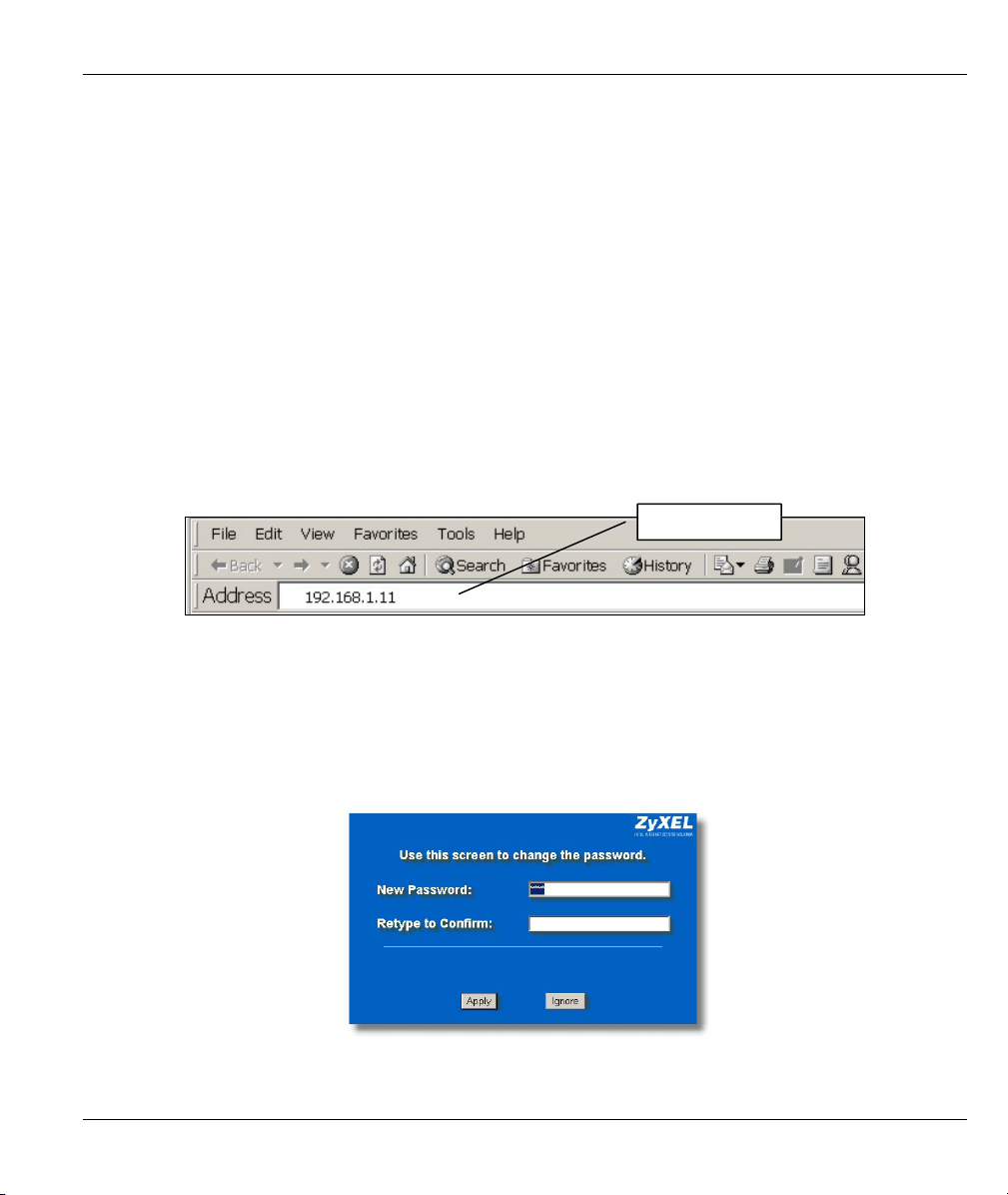
Step 3. Launch your web browser.
Step 4. Type "192.168.1.11" (default) as the URL.
ddress field.
Figure 2-1 Web Browser Address Field
Step 5. Type "1234" (default) as the password and click Login. In some versions, the default password
appears automatically - if this is the case, click Login.
Step 6. You should see a screen asking you to change your password (highly recommended) as shown
next. Type a new password (and retype it to confirm) and click Apply or click Ignore to allow
access without password change.
Figure 2-2 Change Password Screen
Introducing the Web Configurator 2-1
Page 24
ZyAIR B-420 Wireless LAN Ethernet Adapter and Bridge
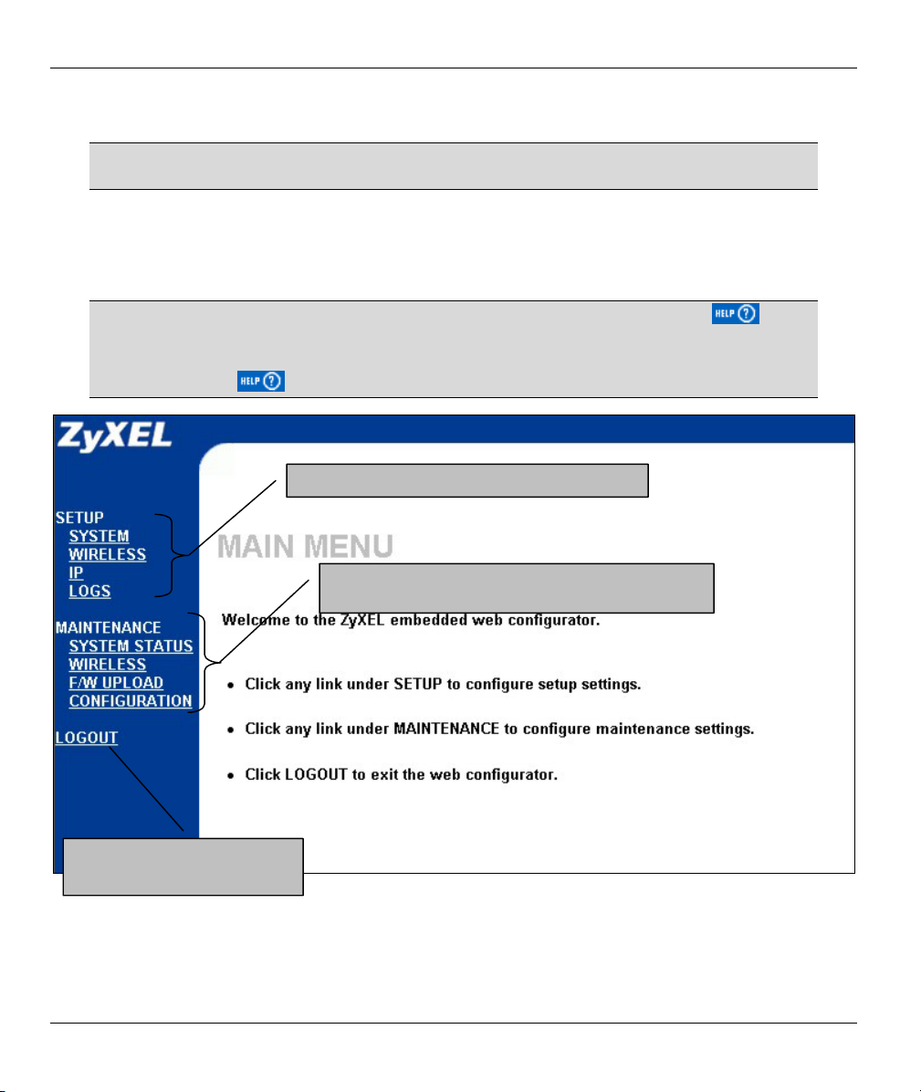
Step 7. You should now see the MAIN MENU screen.
The ZyAIR automatically times out after five minutes of inactivity. Simply log back
into the ZyAIR if this happens to you.
2.2 Navigating the ZyAIR Web Configurator
The following summarizes how to navigate the web configurator from the MAIN MENU screen.
Follow the instructions you see in the MAIN MENU screen or click the icon
(located in the top right corner of most screens) to view online help.
The icon does not appear in the MAIN MENU screen.
Use these submenus to configure ZyAIR features.
Use these submenus to view information about your
ZyAIR or upgrade configuration and firmware files.
Click LOGOUT at any time to
exit the web configurator.
Figure 2-3 The MAIN MENU Screen of the Web Configurator
2-2 Introducing the Web Configurator
Page 25

ZyAIR B-420 Wireless LAN Ethernet Adapter and Bridge
2.3 Resetting the ZyAIR
If you forget your password or cannot access the ZyAIR, you will need to reload the factory-default
configuration file or use the RESET button on the top panel of the ZyAIR. Uploading this configuration file
replaces the current configuration file with the factory-default configuration file. This means that you will
lose all configurations that you had previously. The password will be reset to “1234”, also.
2.3.1 Method of Restoring Factory-Defaults
You can erase the current configuration and restore factory defaults in three ways:
1. Use the RESET button on the top panel of the ZyAIR to upload the default configuration file (hold this
button in for about 10 seconds or until the Link LED turns red). Use this method for cases when the
password or IP address of the ZyAIR is not known.
2. Use the web configurator to restore defaults (refer to the Maintenance chapter).
3. Transfer the configuration file to your ZyAIR using FTP. See the part on SMT configuration for more
information.
Introducing the Web Configurator 2-3
Page 26

System, Wireless and IP
Part II:
SYSTEM, WIRELESS AND IP
This part covers System, Wireless and IP web configurator screens.
II
Page 27

Page 28
ZyAIR B-420 Wireless LAN Ethernet Adapter and Bridge
This chapter provides information on the System screens.
3.1 System Overview
This section provides information on general system setup.
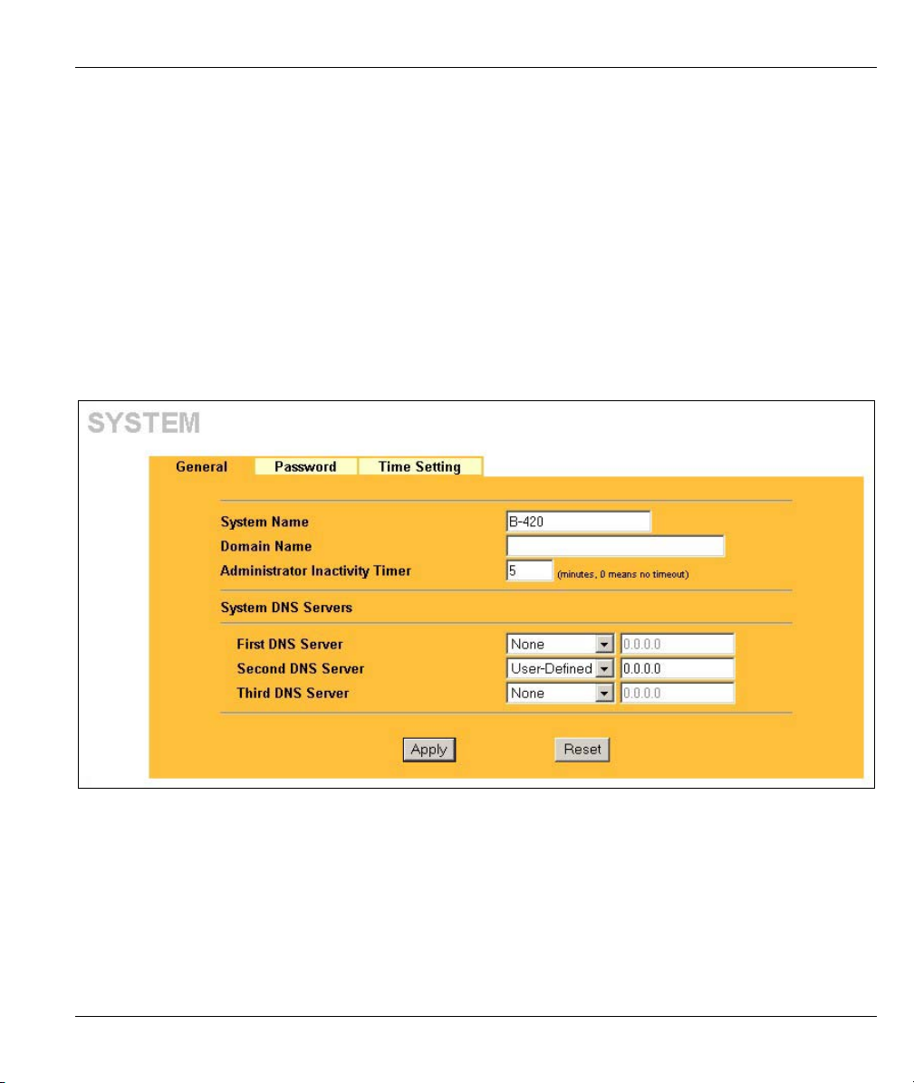
3.2 Configuring General Setup
Click SYSTEM under SETUP to open the General screen.
Chapter 3
System Screens
Figure 3-1 System General Setup
The following table describes the labels in this screen.
System Screens 3-1
Page 29

ZyAIR B-420 Wireless LAN Ethernet Adapter and Bridge
Table 3-1 System General Setup
LABEL DESCRIPTION
System Name Type a descriptive name to identify the ZyAIR in the Ethernet network.
This name can be up to 30 alphanumeric characters long. Spaces are not allowed, but
dashes "-" and underscores "_" are accepted.
Domain Name This is not a required field. Leave this field blank or enter the domain name here if you
know it.
Administrator
Inactivity Timer
System DNS Servers
First DNS Server
Second DNS
Server
Third DNS
Server
Apply
Reset
Type how many minutes a management session (either via the web configurator or
SMT) can be left idle before the session times out.
The default is 5 minutes. After it times out you have to log in with your password again.
Very long idle timeouts may have security risks.
A value of "0" means a management session never times out, no matter how long it
has been left idle (not recommended).
Select From DHCP if your DHCP server dynamically assigns DNS server information
(and the ZyAIR's Ethernet IP address). The field to the right displays the (read-only)
DNS server IP address that the DHCP assigns.
Select User-Defined if you have the IP address of a DNS server. Enter the DNS
server's IP address in the field to the right. If you chose User-Defined, but leave the IP
address set to 0.0.0.0, User-Defined changes to None after you click Apply. If you set
a second choice to User-Defined, and enter the same IP address, the second User-
Defined changes to None after you click Apply.
Select None if you do not want to configure DNS servers. If you do not configure a
DNS server, you must know the IP address of a machine in order to access it.
The default setting is None.
Click Apply to save your changes back to the ZyAIR.
Click Reset to reload the previous configuration for this screen.
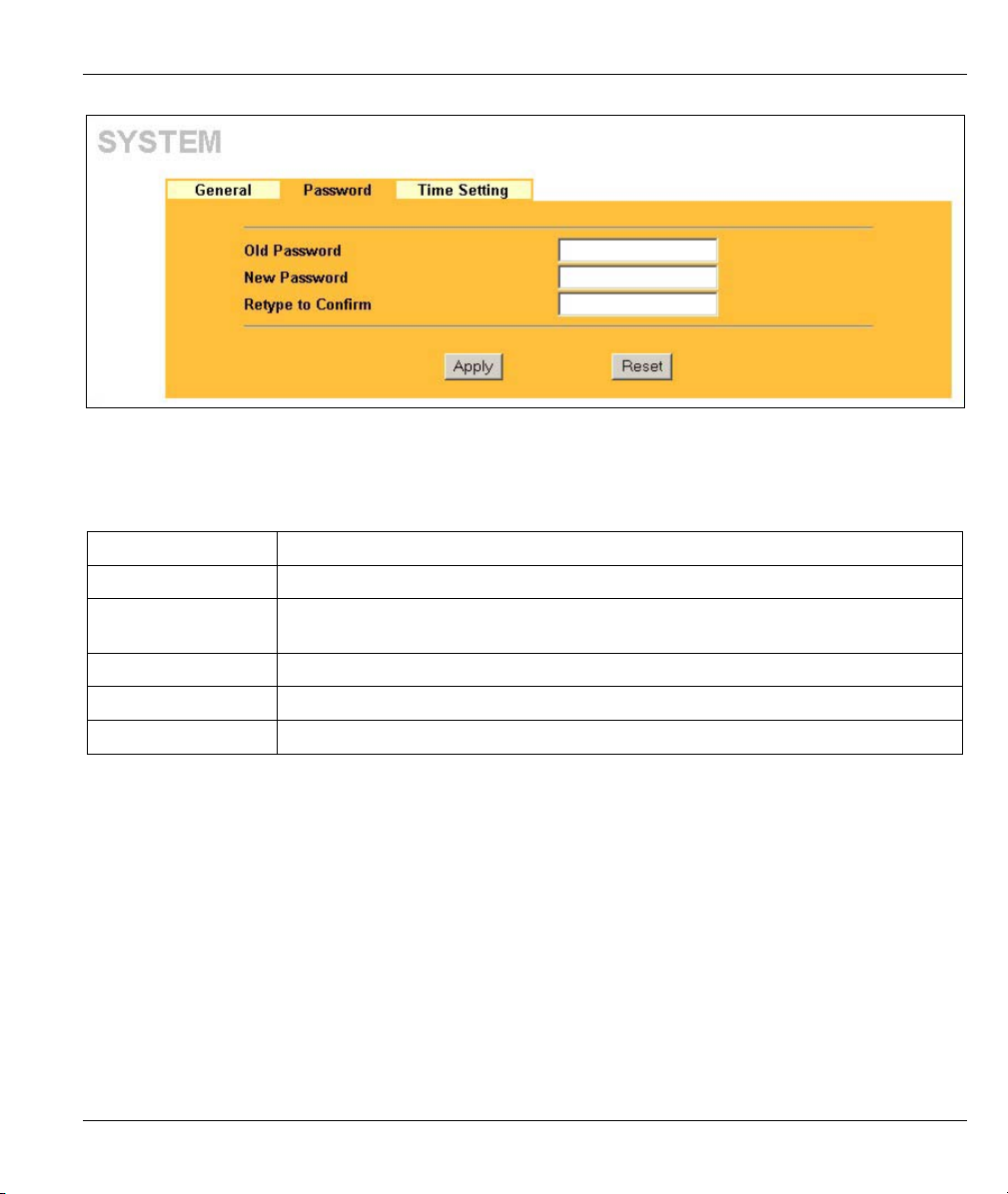
3.3 Configuring Password
To change your ZyAIR’s password (recommended), click SYSTEM under SETUP and then the Password
tab. The screen appears as shown. This screen allows you to change the ZyAIR’s password.
If you forget your password (or the ZyAIR IP address), you will need to reset the ZyAIR. See the Resetting
the ZyAIR section for details.
3-2 System Screens
Page 30
ZyAIR B-420 Wireless LAN Ethernet Adapter and Bridge
Figure 3-2 Password
The following table describes the labels in this screen.
Table 3-2 Password
LABEL DESCRIPTION
Old Password Type in your existing system password (1234 is the default password).
New Password Type your new system password (up to 31 characters). Note that as you type a
password, the screen displays an asterisk (*) for each character you type.
Retype to Confirm Type your new system password again for confirmation.
Apply
Reset
Click Apply to save your changes back to the ZyAIR.
Click Reset to reload the previous configuration for this screen.
3.4 Configuring Time Setting
To change your ZyAIR’s time and date, click SYSTEM under SETUP and then the Time Setting tab. The
screen appears as shown. Use this screen to configure the ZyAIR’s system time.
System Screens 3-3
Page 31

ZyAIR B-420 Wireless LAN Ethernet Adapter and Bridge
Figure 3-3 Time Setting
The following table describes the labels in this screen.
Table 3-3 Time Setting
LABEL DESCRIPTION
Current Time
(hh:mm:ss)
New Time
(hh:mm:ss)
Current Date
(yyyy:mm:dd)
New Date
(yyyy:mm:dd)
Apply
Reset
This field displays the time of your ZyAIR.
Enter the new time in this field.
This field displays the date of your ZyAIR.
Enter the new date in this field.
Click Apply to save your changes back to the ZyAIR.
Click Reset to reload the previous configuration for this screen.
3-4 System Screens
Page 32

ZyAIR B-420 Wireless LAN Ethernet Adapter and Bridge
Chapter 4
Wireless LAN
This chapter discusses how to configure Wireless LAN screens on the ZyAIR.
4.1 Wireless LAN Basis
This section provides basic background information on the wireless LAN screens.
4.1.1 Channel
The range of radio frequencies used by IEEE 802.11b wireless devices is called a “channel”. Channels
available depend on your geographical area. You may have a choice of channels (for your region) so you
should use a different channel than an adjacent AP (access point) to reduce interference. Interference occurs
when radio signals from different access points overlap causing interference and degrading performance.
Adjacent channels partially overlap however. To avoid interference due to overlap, your ZyAIR should be on
a channel at least five channels away from a channel that an adjacent AP is using. For example, if your
region has 11 channels and an adjacent AP is using channel 1, then you need to select a channel between 6 or
11.
The ZyAIR’s “Scan” function is especially designed to automatically scan for a channel with the least
interference.
4.1.2 ESS ID
An Extended Service Set (ESS) is a group of access points connected to a wired LAN on the same subnet. An
ESS ID uniquely identifies each set. All access points and their associated wireless stations in the same set
must have the same ESSID.
4.1.3 WEP Encryption
WEP (Wired Equivalent Privacy) encrypts data frames before transmitting over the wireless network. WEP
encryption scrambles the data transmitted between the wireless stations and the access points to keep network
communications private. It encrypts unicast and multicast communications in a network. Both the wireless
stations and the access points must use the same WEP key for data encryption and decryption.
4.1.4 RTS/CTS
A hidden node occurs when two stations are within range of the same access point, but are not within range
of each other. The following figure illustrates a hidden node. Both stations (STA) are within range of the
access point (AP) or wireless gateway, but out-of-range of each other, so they cannot “hear” each other, that
Wireless LAN 4-1
Page 33

ZyAIR B-420 Wireless LAN Ethernet Adapter and Bridge
is they do not know if the channel is currently being used. Therefore, they are considered hidden from each
other.
Figure 4-1 RTS/CTS
When station A sends data to the ZyAIR, it might not know that station B is already using the channel. If
these two stations send data at the same time, collisions may occur when both sets of data arrive at the AP at
the same time, resulting in a loss of messages for both stations.
RTS/CTS is designed to prevent collisions due to hidden nodes. An RTS/CTS defines the biggest size data
frame you can send before an RTS (Request To Send)/CTS (Clear to Send) handshake is invoked.
When a data frame exceeds the RTS/CTS value you set (between 0 to 2432 bytes), the station that wants to
transmit this frame must first send an RTS (Request To Send) message to the AP for permission to send it.
The AP then responds with a CTS (Clear to Send) message to all other stations within its range to notify
them to defer their transmission. It also reserves and confirms with the requesting station the time frame for
the requested transmission.
Stations can send frames smaller than the specified RTS/CTS directly to the AP without the RTS (Request
To Send)/CTS (Clear to Send) handshake.
You should only configure RTS/CTS if the possibility of hidden nodes exists on your network and the “cost”
of resending large frames is more than the extra network overhead involved in the RTS (Request To
Send)/CTS (Clear to Send) handshake.
If the RTS/CTS value is greater than the Fragmentation Threshold value (see next), then the RTS (Request
To Send)/CTS (Clear to Send) handshake will never occur as data frames will be fragmented before they
reach RTS/CTS size.
Enabling the RTS Threshold causes redundant network overhead that could
negatively affect the throughput performance instead of providing a remedy.
4-2 Wireless LAN
Page 34

ZyAIR B-420 Wireless LAN Ethernet Adapter and Bridge
4.1.5 Fragmentation Threshold
A Fragmentation Threshold is the maximum data fragment size (between 256 and 2432 bytes) that can be
sent in the wireless network before the ZyAIR will fragment the packet into smaller data frames.
A large Fragmentation Threshold is recommended for networks not prone to interference while you should
set a smaller threshold for busy networks or networks that are prone to interference.
If the Fragmentation Threshold value is smaller than the RTS/CTS value (see previously) you set, then the
RTS (Request To Send)/CTS (Clear to Send) handshake will never occur as data frames will be fragmented
before they reach RTS/CTS size.
4.2 Wireless Security Overview
Wireless security is vital to your network to protect wireless communication between wireless stations,
access points and the wired network.
The figure below shows the possible wireless security levels on your ZyAIR. The highest security level relies
on EAP (Extensible Authentication Protocol) for authentication and utilizes dynamic WEP key exchange. It
requires interaction with a RADIUS (Remote Authentication Dial-In User Service) server either on the WAN
or your LAN to provide authentication service for wireless stations.
Figure 4-2 ZyAIR Wireless Security Levels
If you do not enable any wireless security on your ZyAIR, your network is accessible to any wireless
networking device that is within range.
4.3 WEP Overview
WEP (Wired Equivalent Privacy) as specified in the IEEE 802.11 standard provides methods for both data
encryption and wireless station authentication.
Wireless LAN 4-3
Page 35

ZyAIR B-420 Wireless LAN Ethernet Adapter and Bridge
4.3.1 Data Encryption
WEP provides a mechanism for encrypting data using encryption keys. The values for the keys must be set
up exactly the same on the APs or other peer ad-hoc wireless computers as they are on the ZyAIR to encrypt
and decrypt data. Your ZyAIR allows you to configure up to four 64-bit or 128-bit WEP keys, but only one
key can be enabled at any one time.
4.3.2 Authentication
Three different methods can be used to authenticate wireless stations to the network: Open System, Shared
Key, and Auto. The following figure illustrates the steps involved.
Figure 4-3 WEP Authentication Steps
Open system authentication involves an unencrypted two-message procedure. A wireless station sends an
open system authentication request to the AP, which will then automatically accept and connect the wireless
station to the network. In effect, open system is not authentication at all as any station can gain access to the
network.
Shared key authentication involves a four-message procedure. A wireless station sends a shared key
authentication request to the AP, which will then reply with a challenge text message. The wireless station
4-4 Wireless LAN
Page 36

ZyAIR B-420 Wireless LAN Ethernet Adapter and Bridge
must then use the AP’s default WEP key to encrypt the challenge text and return it to the AP, which attempts
to decrypt the message using the AP’s default WEP key. If the decrypted message matches the challenge text,
the wireless station is authenticated.
When your ZyAIR's authentication method is set to open system, it will only accept open system
authentication requests. The same is true for shared key authentication. However, when it is set to auto
authentication, the ZyAIR will accept either type of authentication request and the ZyAIR will fall back to
use open authentication if the shared key does not match.
4.4 Configuring Wireless
Click WIRELESS under SETUP to display the Wireless screen.
To use your ZyAIR as a wireless LAN adapter, select the Infrastructure or Ad Hoc operating mode. To use
your ZyAIR as a wireless LAN bridge connecting two wired network segments, select the Bridge operating
mode. The screen varies according to the operating mode you select.
4.4.1 Infrastructure
An infrastructure network, also called a Basic Service Set (BSS), exists when all communications between
wireless stations or between a wireless station and a wired network client go through one access point (AP).
Figure 4-4 Infrastructure Network Example
Wireless LAN 4-5
Page 37

ZyAIR B-420 Wireless LAN Ethernet Adapter and Bridge
Roaming
In an infrastructure network, wireless stations are able to switch from one AP to another as they move
between the coverage areas. During this period, the wireless stations maintain uninterrupted connections to
the network. This is roaming. As the wireless station moves from place to place, it is responsible for choosing
the most appropriate AP depending on the signal strength, network utilization or other factors.
The following figure depicts a simple roaming example. When Wireless Station B moves to position X, the
ZyAIR in Wireless Station B automatically switches the channel to the one used by AP 2 in order to stay
connected to the network.
Figure 4-5 Roaming Example
Select Infrastructure from the Operating Mode drop-down list box to display the screen as shown.
4-6 Wireless LAN
Page 38

ZyAIR B-420 Wireless LAN Ethernet Adapter and Bridge
Figure 4-6 Wireless : Infrastructure
The following table describes the labels in this screen.
Table 4-1 Wireless : Infrastructure
LABEL DESCRIPTION
Operating Mode
ESSID In this field enter the ESSID of the AP to which you want to associate. To associate to
RTS/CTS
Threshold
Select Infrastructure from the drop-down list.
an ad-hoc network, you must enter the same ESSID as the peer ad-hoc computer.
Enter Any to associate to or roam between any infrastructure wireless networks.
Enter a value between 0 and 2432. The default is 2432.
Wireless LAN 4-7
Page 39

ZyAIR B-420 Wireless LAN Ethernet Adapter and Bridge
Table 4-1 Wireless : Infrastructure
LABEL DESCRIPTION
Fragmentation
Threshold
WEP Encryption
Authentication
Method
ASCII Select this option to enter ASCII characters as the WEP keys.
Hex Select this option to enter hexadecimal characters as the WEP keys.
Key 1 to
Key 4
Enable
Breathing LED
Apply
Reset
Enter a value between 256 and 2432.
It is the maximum data fragment size that can be sent.
Select Disable to allow wireless stations to communicate with the AP without any data
encryption.
Select 64-bit WEP or 128-bit WEP to enable data encryption.
Select Auto, Open System Only or Shared Key Only from the drop-down list box.
This field is N/A if WEP is not activated.
If WEP encryption is activated, the default setting is Auto.
The preceding “0x” is entered automatically.
The WEP keys are used to encrypt data. Both the AP and the wireless stations must
use the same WEP key for data transmission.
If you chose 64-bit WEP, then enter any 5 ASCII characters or 10 hexadecimal
characters ("0-9", "A-F").
If you chose 128-bit WEP, then enter 13 ASCII characters or 26 hexadecimal
characters ("0-9", "A-F").
You must configure all four keys, but only one key can be activated at any one time.
The default key is key 1.
Select this check box to enable the Breathing LED, also known as the ZyAIR LED.
The blue ZyAIR LED is on when the ZyAIR is on and blinks (or breaths) when data is
being transmitted to/from its wireless stations. Clear the check box to turn this LED off
even when the ZyAIR is on and data is being transmitted/received.
Click Apply to save your changes back to the ZyAIR.
Click Reset to begin configuring this screen afresh.
4.4.2 Ad-Hoc
An Ad-hoc network, also called an Independent Basic Service Set (IBSS), is the simplest WLAN
configuration. An Ad-hoc network is defined as two or more computers with wireless adapters within range
of each other that from an independent (wireless) network without the need of an access point (AP).
4-8 Wireless LAN
Page 40

ZyAIR B-420 Wireless LAN Ethernet Adapter and Bridge
Figure 4-7 Ad-hoc (IBSS) Wireless LAN
Select Ad Hoc in the Operating Mode drop-down list box to display the screen as shown.
Figure 4-8 Wireless : Ad Hoc
Wireless LAN 4-9
Page 41

ZyAIR B-420 Wireless LAN Ethernet Adapter and Bridge
The following table describes the additional fields that display when you select the Ad Hoc operating mode
in the Wireless screen.
Table 4-2 Wireless : Ad Hoc
LABEL DESCRIPTION
Operating Mode
ESSID In this field enter the ESSID of the peer ad-hoc computer to which you want to
Choose
Channel ID
Scan Click this button to have the ZyAIR automatically scan for and select a channel with the
Select Ad Hoc in this field to display the screen.
associate. To associate to an ad-hoc network, you must enter the same ESSID as the
peer ad-hoc computer.
Enter Any to associate to or roam between any infrastructure wireless networks.
Set the operating frequency/channel depending on your particular region.
To manually set the ZyAIR to use a channel, select a channel from the drop-down list
box. Click WIRELESS under MAINTENANCE to open the Channel Usage screen to
make sure the channel is not already used by another AP or independent peer-to-peer
wireless network.
To have the ZyAIR automatically select a channel, click Scan instead.
least interference.
4.4.3 Bridge
The ZyAIR can function as a wireless network bridge allowing you to wirelessly connect two wired network
segments. You need to know the MAC address of the peer device, which also must be in bridge mode. In the
example below, Computers B and C will be able to communicate with Computer A through the ZyAIR
bridges, forming a Wireless Distribution System (WDS).
Figure 4-9 Bridging Example
4-10 Wireless LAN
Page 42

ZyAIR B-420 Wireless LAN Ethernet Adapter and Bridge
Be careful to avoid bridge loops when you enable bridging in the ZyAIR. Bridge loops cause broadcast
traffic to circle the network endlessly, resulting in possible throughput degradation and disruption of
communications. The following examples show two network topologies that can lead to this problem:
If two or more ZyAIRs (in bridge mode) are connected to the same hub as shown next.
Figure 4-10 Bridge Loop: Two Bridges Connected to Hub
If your ZyAIR (in bridge mode) is connected to a wired LAN while communicating with another
wireless bridge that is also connected to the same wired LAN as shown next.
Figure 4-11 Bridge Loop: Bridge Connected to Wired LAN
To prevent bridge loops, ensure that your ZyAIR is not set to bridge mode while connected to both wired and
wireless segments of the same LAN.
Wireless LAN 4-11
Page 43

ZyAIR B-420 Wireless LAN Ethernet Adapter and Bridge
Click WIRELESS under SETUP. Select Bridge in the Operating Mode drop-down list box to display the
screen as shown.
Figure 4-12 Wireless : Bridge
The following table describes the additional fields that display when you select the Bridge operating mode in
the Wireless screen.
Table 4-3 Wireless : Bridge
LABEL DESCRIPTION
Operating Mode
Select Bridge in this field to display the screen as shown in Figure 4-12.
4-12 Wireless LAN
Page 44

ZyAIR B-420 Wireless LAN Ethernet Adapter and Bridge
Table 4-3 Wireless : Bridge
LABEL DESCRIPTION
Peer Bridge
MAC Address
WEP Encryption
Authentication
Method
ASCII Select this option to enter ASCII characters as the WEP keys.
Hex Select this option to enter hexadecimal characters as the WEP keys.
Key 1 to
Key 4
Enable
Breathing LED
Output Power Set the output power of the ZyAIR in this field. If there is a high density of APs within
Type the MAC address of peer device in valid MAC address format, that is, six
hexadecimal character pairs, for example, 12:34:56:78:9a:bc.
Select Disable to allow wireless stations to communicate with the AP without any data
encryption.
Select 64-bit WEP or 128-bit WEP to enable data encryption.
Select Auto, Open System Only or Shared Key Only from the drop-down list box.
This field is N/A if WEP is not activated.
If WEP encryption is activated, the default setting is Auto.
The preceding “0x” is entered automatically.
The WEP keys are used to encrypt data. Both the AP and the wireless stations must
use the same WEP key for data transmission.
If you chose 64-bit WEP, then enter any 5 ASCII characters or 10 hexadecimal
characters ("0-9", "A-F").
If you chose 128-bit WEP, then enter 13 ASCII characters or 26 hexadecimal
characters ("0-9", "A-F").
You must configure all four keys, but only one key can be activated at any one time.
The default key is key 1.
Select this check box to enable the Breathing LED, also known as the ZyAIR LED.
The blue ZyAIR LED is on when the ZyAIR is on and blinks (or breaths) when data is
being transmitted to/from its wireless stations. Clear the check box to turn this LED off
even when the ZyAIR is on and data is being transmitted/received.
an area, decrease the output power of the ZyAIR to reduce interference with other
APs.
The options are 11dBm (12.6mW), 13dBm (20mW), 15dBm (32mW) or 17dBm
(50mW).
Wireless LAN 4-13
Page 45

Page 46

ZyAIR B-420 Wireless LAN Ethernet Adapter and Bridge
Chapter 5
IP Screen
This chapter discusses how to configure IP on the ZyAIR.
5.1 Factory Ethernet Defaults
The Ethernet parameters of the ZyAIR are preset in the factory with the following values:
• IP address of 192.168.1.11
• Subnet mask of 255.255.255.0 (24 bits)
These parameters should work for the majority of installations.
5.2 TCP/IP Parameters
5.2.1 IP Address and Subnet Mask
Similar to the way houses on a street share a common street name, so too do computers on a LAN share one
common network number.
Where you obtain your network number depends on your particular situation. If the ISP or your network
administrator assigns you a block of registered IP addresses, follow their instructions in selecting the IP
addresses and the subnet mask.
The Internet Assigned Number Authority (IANA) reserved this block of addresses specifically for private
use; please do not use any other number unless you are told otherwise. Let's say you select 192.168.1.0 as the
network number; which covers 254 individual addresses, from 192.168.1.1 to 192.168.1.254 (zero and 255
are reserved). In other words, the first three numbers specify the network number while the last number
identifies an individual computer on that network.
Once you have decided on the network number, pick an IP address that is easy to remember, for instance,
192.168.1.11, for your ZyAIR, but make sure that no other device on your network is using that IP address.
The subnet mask specifies the network number portion of an IP address. Your ZyAIR will compute the
subnet mask automatically based on the IP address that you entered. You don't need to change the subnet
mask computed by the ZyAIR unless you are instructed to do otherwise.
Every computer on the Internet must have a unique IP address. If your networks are isolated from the
Internet, for instance, only between your two branch offices, you can assign any IP addresses to the hosts
without problems. However, the Internet Assigned Numbers Authority (IANA) has reserved the following
three blocks of IP addresses specifically for private networks.
IP 5-1
Page 47

ZyAIR B-420 Wireless LAN Ethernet Adapter and Bridge
Table 5-1 Private IP Address Ranges
10.0.0.0 - 10.255.255.255
172.16.0.0 - 172.31.255.255
192.168.0.0 - 192.168.255.255
You can obtain your IP address from the IANA, from an ISP or have it assigned by a private network. If you
belong to a small organization and your Internet access is through an ISP, the ISP can provide you with the
Internet addresses for your local networks. On the other hand, if you are part of a much larger organization,
you should consult your network administrator for the appropriate IP addresses.
Regardless of your particular situation, do not create an arbitrary IP address;
always follow the guidelines above. For more information on address assignment,
please refer to RFC 1597, Address Allocation for Private Internets and RFC 1466,
Guidelines for Management of IP Address Space.
5.3 Configuring IP
Click IP to display the screen shown next.
Figure 5-1 IP
5-2 IP
Page 48

ZyAIR B-420 Wireless LAN Ethernet Adapter and Bridge
The following table describes the labels in this screen.
Table 5-2 IP
LABEL DESCRIPTION
IP Address Assignment
Get automatically Select this option if your ZyAIR is using a dynamically assigned IP address from
a DHCP server each time.
You must know the IP address assigned to the ZyAIR (by
the DHCP server) to access the ZyAIR again.
Use fixed IP address Select this option if your ZyAIR is using a static IP address. When you select
this option, fill in the fields below.
IP Address Enter the IP address of your ZyAIR in dotted decimal notation.
If you change the ZyAIR's IP address, you must use the
new IP address if you want to access the web
configurator again.
IP Subnet Mask Type the subnet mask.
Gateway IP Address Type the IP address of the gateway. The gateway is an immediate neighbor of
your ZyAIR that will forward the packet to the destination. On the LAN, the
gateway must be a router on the same segment as your ZyAIR.
Apply
Reset
Click Apply to save your changes back to the ZyAIR.
Click Reset to begin configuring this screen afresh.
IP 5-3
Page 49

Logs
Part III:
LOGS
This part provides information and configuration instructions for the logs.
III
Page 50

ZyAIR B-420 Wireless LAN Ethernet Adapter and Bridge
Chapter 6
Logs Screens
This chapter contains information about configuring general log settings and viewing the ZyAIR’s
logs. Refer to the appendix for example log message explanations.
6.1 Configuring View Log
The web configurator allows you to look at all of the ZyAIR’s logs in one location.
Click LOGS under SETUP to open the View Log screen. Use the View Log screen to see the logs for the
categories that you selected in the Log Settings screen (see section 6.2). Options include logs about system
maintenance, system errors and access control.
You can view logs and alert messages in this page. Alerts are displayed in red and logs are displayed in
black. Once the number of log entries are all used, the log will wrap around and the old logs will be deleted.
Click a column heading to sort the entries. A triangle indicates the direction of the sort order.
Figure 6-1 View Log
The following table describes the labels in this screen.
Logs Screens 6-1
Page 51

ZyAIR B-420 Wireless LAN Ethernet Adapter and Bridge
Table 6-1 View Log
LABEL DESCRIPTION
Display Select a log category from the drop down list box to display logs within the selected
category. To view all logs, select All Logs.
The number of categories shown in the drop down list box depends on the selection in
the Log Settings page.
Time This field displays the time the log was recorded.
Message This field states the reason for the log.
Source This field lists the source IP address and the port number of the incoming packet.
Destination This field lists the destination IP address and the port number of the incoming packet.
Note This field displays additional information about the log entry.
Email Log Now
Refresh
Clear Log
Click Email Log Now to send the log screen to the e-mail address specified in the Log
Settings page.
Click Refresh to renew the log screen.
Click Clear Log to clear all the logs.
6.2 Configuring Log Settings
To change your ZyAIR’s log settings, click LOGS under SETUP and then the Log Settings tab. The screen
appears as shown.
Use the Log Settings screen to configure to where the ZyAIR is to send the logs; the schedule for when the
ZyAIR is to send the logs and which logs and/or immediate alerts the ZyAIR is to send.
An alert is a type of log that warrants more serious attention. Some categories such as System Errors consist
of both logs and alerts. You may differentiate them by their color in the View Log screen. Alerts are
displayed in red and logs are displayed in black.
6-2 Logs Screens
Page 52

ZyAIR B-420 Wireless LAN Ethernet Adapter and Bridge
Figure 6-2 Log Settings
The following table describes the labels in this screen.
Table 6-2 Log Settings
LABEL DESCRIPTION
Address Info
Logs Screens 6-3
Page 53

ZyAIR B-420 Wireless LAN Ethernet Adapter and Bridge
Table 6-2 Log Settings
LABEL DESCRIPTION
Mail Server Enter the server name or the IP address of the mail server for the e-mail addresses
specified below. If this field is left blank, logs and alert messages will not be sent via
e-mail.
Mail Subject Type a title that you want to be in the subject line of the log e-mail message that the
ZyAIR sends.
Send Log to Logs are sent to the e-mail address specified in this field. If this field is left blank,
logs will not be sent via e-mail.
Send Alerts to Enter the e-mail address where the alert messages will be sent. If this field is left
blank, alert messages will not be sent via e-mail.
Syslog Logging
Active
Syslog IP Address Enter the server name or the IP address of the syslog server that will log the CDR
Log Facility
Send Log
Log Schedule This drop-down menu is used to configure the frequency of log messages being
Day for Sending Log
Time for Sending Log Enter the time of the day in 24-hour format (for example 23:00 equals 11:00 pm) to
Log Select the categories of logs that you want to record.
Click Active to enable UNIX syslog.
(Call Detail Record) and system messages.
Select the Local from the drop down list box. The log facility allows you to log the
messages to different files in the syslog server. Refer to your UNIX manual for more
information.
sent as E-mail:
• Daily
• Weekly
• Hourly
• When the Log is Full
• None.
If the Weekly or the Daily option is selected, specify a time of day when the E-mail
should be sent. If the Weekly option is selected, then also specify which day of the
week the E-mail should be sent. If the When Log is Full option is selected, an alert
is sent when the log fills up. If you select None, no log messages are sent.
This field is only available when you select Weekly in the Log Schedule field.
Use the drop down list box to select which day of the week to send the logs.
send the logs.
6-4 Logs Screens
Page 54

ZyAIR B-420 Wireless LAN Ethernet Adapter and Bridge
Table 6-2 Log Settings
LABEL DESCRIPTION
Send Immediate Alert Select the categories of alerts for which you want the ZyAIR to immediately send
e-mail alerts.
Apply
Reset
Click Apply to save your customized settings and exit this screen.
Click Reset to reconfigure all the fields in this screen.
Logs Screens 6-5
Page 55

Maintenance
Part IV:
MAINTENANCE
This part describes the Maintenance web configurator screens.
IV
Page 56

Page 57

ZyAIR B-420 Wireless LAN Ethernet Adapter and Bridge
Chapter 7
Maintenance
This chapter displays system information such as ZyNOS firmware, port IP addresses and port
traffic statistics.
7.1 Maintenance Overview
The maintenance screens can help you view system information, upload new firmware, manage configuration
and restart your ZyAIR.
7.2 System Status Screen
Click MAINTENANCE to open the System Status screen, where you can use to monitor your ZyAIR. Note
that these fields are READ-ONLY and are meant to be used for diagnostic purposes.
Figure 7-1 System Status
The following table describes the labels in this screen.
Table 7-1 System Status
LABEL DESCRIPTION
System Name
Maintenance 7-1
This is the System Name you enter in the first Internet Access Wizard screen. It is
for identification purposes
Page 58

ZyAIR B-420 Wireless LAN Ethernet Adapter and Bridge
Table 7-1 System Status
LABEL DESCRIPTION
ZyNOS Firmware
Version
IP Address This is the Ethernet port IP address.
IP Subnet Mask This is the Ethernet port subnet mask.
DHCP
Show Statistics
This is the ZyNOS Firmware version and the date created. ZyNOS is ZyXEL's
proprietary Network Operating System design.
This is the Ethernet port DHCP role - Client or None.
Click Show Statistics to see router performance statistics such as number of
packets sent and number of packets received for each port.
7.2.1 System Statistics
Read-only information here includes port status and packet specific statistics. Also provided are "system up
time" and "poll interval". The Poll Interval field is configurable.
Figure 7-2 System Status: Show Statistics
The following table describes the labels in this screen.
Table 7-2 System Status: Show Statistics
LABEL DESCRIPTION
Port This is the Ethernet or wireless port.
7-2 Maintenance
Page 59

ZyAIR B-420 Wireless LAN Ethernet Adapter and Bridge
Table 7-2 System Status: Show Statistics
LABEL DESCRIPTION
Status This shows the port speed and duplex setting if you are using Ethernet encapsulation for
the Ethernet port.
This shows the transmission speed only for wireless port.
TxPkts This is the number of transmitted packets on this port.
RxPkts This is the number of received packets on this port.
Collisions This is the number of collisions on this port.
Tx B/s This shows the transmission speed in bytes per second on this port.
Rx B/s This shows the reception speed in bytes per second on this port.
Up Time This is total amount of time the line has been up.
System Up Time This is the total time the ZyAIR has been on.
Poll Interval Enter the time interval for refreshing statistics.
Set Interval Click this button to apply the new poll interval you entered above.
Stop Click this button to stop refreshing statistics.
7.3 Wireless Screen
The Channel Usage screen shows whether a channel is used by another wireless network or not. If a channel
is being used, you should select a channel removed from it by five channels to completely avoid overlap.
Click WIRELESS under MAINTENANCE to display the screen as shown next.
Wait a moment while the ZyAIR compiles the information.
Maintenance 7-3
Page 60

ZyAIR B-420 Wireless LAN Ethernet Adapter and Bridge
Figure 7-3 Channel Usage
The following table describes the labels in this screen.
Table 7-3 Channel Usage
LABEL DESCRIPTION
This is the Service Set IDentification name of the AP in an Infrastructure wireless
network or wireless station in an Ad-Hoc wireless network. For our purposes, we define
SSID
MAC Address
Channel
Signal
an Infrastructure network as a wireless network that uses an AP and an Ad-Hoc network
(also known as Independent Basic Service Set (IBSS)) as one that doesn’t. See the
Wireless LAN chapter for more information on basic service sets (BSS) and extended
service sets (ESS).
This field displays the MAC address of the AP in an Infrastructure wireless network. It is
randomly generated (so ignore it) in an Ad-Hoc wireless network.
This is the index number of the channel currently used by the associated AP in an
Infrastructure wireless network or wireless station in an Ad-Hoc wireless network.
This field displays the strength of the AP’s signal. If you must choose a channel that’s
currently in use, choose one with low signal strength for minimum interference.
7-4 Maintenance
Page 61

ZyAIR B-420 Wireless LAN Ethernet Adapter and Bridge
Table 7-3 Channel Usage
LABEL DESCRIPTION
“Network mode” in this screen refers to your wireless LAN infrastructure (refer to the
Wireless LAN chapter) and WEP setup.
Network Mode
Refresh
Network modes are: Infra (same as an extended service set ESS), Infra, WEP (WEP
encryption is enabled), Ad-Hoc (same as an independent basic service set IBSS), or Ad-
Hoc, WEP.
Click Refresh to reload the screen.
7.4 F/W Upload Screen
Find firmware at www.zyxel.com in a file that (usually) uses the system model name with a "*.bin"
extension, e.g., "zyair.bin". The upload process uses HTTP (Hypertext Transfer Protocol) and may take up to
two minutes. After a successful upload, the system will reboot. See the Firmware and Configuration File
Maintenance chapter for upgrading firmware using FTP/TFTP commands.
Click F/W UPLOAD under MAINTENANCE. Follow the instructions in this screen to upload firmware to
your ZyAIR.
Figure 7-4 Firmware Upload
The following table describes the labels in this screen.
Maintenance 7-5
Page 62

ZyAIR B-420 Wireless LAN Ethernet Adapter and Bridge
Table 7-4 Firmware Upload
LABEL DESCRIPTION
File Path
Browse...
Upload
Type in the location of the file you want to upload in this field or click Browse ... to find it.
Click Browse... to find the .bin file you want to upload. Remember that you must decompress
compressed (.zip) files before you can upload them.
Click Upload to begin the upload process. This process may take up to two minutes.
WARNING!
Do not interrupt the file transfer process as this may PERMANENTLY DAMAGE
YOUR ZyAIR. When the firmware upload process is complete, the ZyAIR will
automatically restart.
After you see the Firmware Upload in Process screen, wait two minutes before logging into the device
again.
Figure 7-5 Firmware Upload In Process
The ZyAIR automatically restarts in this time causing a temporary network disconnect. In some operating
systems, you may see the following icon on your desktop.
7-6 Maintenance
Page 63

ZyAIR B-420 Wireless LAN Ethernet Adapter and Bridge
Figure 7-6 Network Temporarily Disconnected
After two minutes, log in again and check your new firmware version in the System Status screen.
If the upload was not successful, the following screen will appear. Click Return to go back to the F/W
Upload screen.
Figure 7-7 Firmware Upload Error
7.5 Configuration Screen
The web configurator uses TFTP to transfer files. See the Firmware and Configuration File Maintenance
chapter for transferring configuration files using FTP/TFTP commands.
Click MAINTENANCE and then CONFIGURATION. Information related to backup configuration,
restoring configuration and factory defaults appears as shown next.
7.5.1 Backup Configuration
Backup Configuration allows you to backup (save) the current system (ZyAIR) configuration to your
computer. Backup is highly recommended once your ZyAIR is functioning properly.
Click Backup to save your current ZyAIR configuration to your computer.
Maintenance 7-7
Page 64

ZyAIR B-420 Wireless LAN Ethernet Adapter and Bridge
Figure 7-8 Backup Configuration
7.5.2 Restore Configuration
Restore configuration replaces your ZyAIR's current configuration with a previously saved configuration.
Restore files (usually) have a .ROM extension, e.g., "zyair.rom". The system reboots automatically after the
file transfer is complete and uses the configured values in the file.
WARNING!
Do not interrupt the file transfer process as this may PERMANENTLY DAMAGE
YOUR ZyAIR. When the Restore Configuration process is complete, the ZyAIR will
automatically restart.
Figure 7-9 Restore Configuration
The following table describes the labels in this screen.
7-8 Maintenance
Page 65

ZyAIR B-420 Wireless LAN Ethernet Adapter and Bridge
Table 7-5 Restore Configuration
LABEL DESCRIPTION
File Path
Browse...
Upload
Type in the location of the file you want to upload in this field or click Browse ... to find it.
Click Browse... to find the file you want to upload. Remember that you must decompress
compressed (.ZIP) files before you can upload them.
Click Upload to begin the upload process.
Do not turn off the device while configuration file upload is in progress.
After you see a “configuration upload successful” screen, you must then wait one minute before logging into
the ZyAIR again.
Figure 7-10 Configuration Upload Successful
The ZyAIR automatically restarts in this time causing a temporary network disconnect. In some operating
systems, you may see the following icon on your desktop.
Figure 7-11 Network Temporarily Disconnected
If you uploaded the default configuration file you may need to change the IP address of your computer to be
in the same subnet as that of the default ZyAIR IP address (192.168.1.11). See the appendix for details on
how to set up your computer’s IP address.
Maintenance 7-9
Page 66

ZyAIR B-420 Wireless LAN Ethernet Adapter and Bridge
If the upload was not successful, the following screen will appear. Click Return to go back to the
Configuration screen.
Figure 7-12 Configuration Upload Error
7.5.3 Back to Factory Defaults
Clicking the Reset button in this section clears all user-entered configuration information and returns the
ZyAIR to its factory defaults as shown on the screen.
This will erase all configurations that you have applied.
Figure 7-13 Back to Factory Default
The following warning screen will appear.
7-10 Maintenance
Page 67

ZyAIR B-420 Wireless LAN Ethernet Adapter and Bridge
Figure 7-14 Reset Warning Message
You can also press the RESET button on the rear panel to reset the factory defaults of your ZyAIR. Refer to
the Resetting the ZyAIR section for more information on the RESET button.
Maintenance 7-11
Page 68

SMT Configuration
Part V:
SMT CONFIGURATION
This part contains SMT (System Management Terminal) configuration and background
information for features only configurable by SMT.
See the web configurator parts of this guide for background information on
features configurable by web configurator and SMT.
V
Page 69

Page 70

ZyAIR B-420 Wireless LAN Ethernet Adapter and Bridge
Chapter 8
Introducing the SMT
This chapter describes how to access the SMT and provides an overview of its menus.
8.1 Connect to your ZyAIR Using Telnet
The following procedure details how to telnet into your ZyAIR.
Step 1. In Windows, click Start (usually in the bottom left corner), Run and then type “telnet
192.168.1.11” (the default IP address) and click OK.
Step 2. For your first login, enter the default password “1234”. As you type the password, the screen
displays an asterisk “*” for each character you type.
Password : xxxx
Figure 8-1 Login Screen
Step 3. After entering the password you will see the main menu.
Please note that if there is no activity for longer than five minutes (default timeout period) after you log in,
your ZyAIR will automatically log you out. You will then have to telnet into the ZyAIR again. You can use
the web configurator or the CI commands to change the inactivity time out period.
8.2 Changing the System Password
Change the ZyAIR default password by following the steps shown next.
Step 1. From the main menu, enter 23 to display Menu 23 – System Security.
Step 2. Enter 1 to display Menu 23.1 – System Security – Change Password as shown next.
Step 3. Type your existing system password in the Old Password field, and press [ENTER].
Introducing the SMT 8-1
Page 71

ZyAIR B-420 Wireless LAN Ethernet Adapter and Bridge
Menu 23.1 – System Security – Change Password
Old Password= ****
New Password= ?
Retype to confirm= ?
Enter here to CONFIRM or ESC to CANCEL:
Figure 8-2 Menu 23.1 System Security : Change Password
Step 4. Type your new system password in the New Password field (up to 30 characters), and press
[ENTER].
Step 5. Re-type your new system password in the Retype to confirm field for confirmation and press
[ENTER].
Note that as you type a password, the screen displays an asterisk “*” for each character you type.
8.3 ZyAIR SMT Menu Overview Example
The following figure gives you an example overview of the various SMT menu screens for your ZyAIR.
8-2 Introducing the SMT
Page 72

ZyAIR B-420
Main Menu
ZyAIR B-420 Wireless LAN Ethernet Adapter and Bridge
Menu 1
General Setup
Menu 3
LAN Setup
Menu 3.2
TCP/IP Setup
Menu 3.5
Wireless LAN
Setup
Menu 3.5.4
Bridge Link
Configuration
Menu 22
SNMP
Configuration
Menu 23
System Password
Menu 24.2.1
System Maintenance
- Information
Menu 24.3.1
System Maintenance
- View Error Log
Menu 24.7.1
Upload System
Firmware
Menu 24
System
Maintenance
Menu 24.2
System Information and
Console Port Speed
Menu 24.3
System Maintenance
- Log and Trace
Menu 24.1
System Maintenance
- Status
Menu 24.2.2
System Maintenance
- Change Console Port
Spe ed
Menu 24.5
Backup
Configuration
Menu 24.6
Restore
Configuration
Menu 24.7
Upload Firmware
Configuration File
Menu 24.7.2
Upload System
Menu 24.8
Command
Interpreter Mode
Menu 24.10
Time and Date
Setting
Figure 8-3 ZyAIR B-420 SMT Menu Overview Example
Introducing the SMT 8-3
Page 73

ZyAIR B-420 Wireless LAN Ethernet Adapter and Bridge
8.4 Navigating the SMT Interface
The SMT (System Management Terminal) is the interface that you use to configure your ZyAIR.
Several operations that you should be familiar with before you attempt to modify the configuration are
listed in the table below.
Table 8-1 Main Menu Commands
OPERATION KEYSTROKE DESCRIPTION
Move down to
another menu
Move up to a
previous menu
Move to a “hidden”
menu
Move the cursor [ENTER] or
Entering
information
Required fields
N/A fields <N/A> Some of the fields in the SMT will show a <N/A>. This symbol
Save your
configuration
Exit the SMT Type 99, then press
[ENTER] To move forward to a submenu, type in the number of the desired
submenu and press [ENTER].
[ESC] Press [ESC] to move back to the previous menu.
Press [SPACE
BAR] to change No
to Yes then press
[ENTER].
[UP]/[DOWN] arrow
keys.
Type in or press
[SPACE BAR], then
press [ENTER].
<?> or ChangeMe
[ENTER] Save your configuration by pressing [ENTER] at the message
[ENTER].
Fields beginning with “Edit” lead to hidden menus and have a
default setting of No. Press [SPACE BAR] once to change No to
Yes, then press [ENTER] to go to the “hidden” menu.
Within a menu, press [ENTER] to move to the next field. You can
also use the [UP]/[DOWN] arrow keys to move to the previous
and the next field, respectively.
You need to fill in two types of fields. The first requires you to type
in the appropriate information. The second allows you to cycle
through the available choices by pressing [SPACE BAR].
All fields with the symbol <?> must be filled in order to be able to
save the new configuration.
All fields with ChangeMe must not be left blank in order to be
able to save the new configuration.
refers to an option that is Not Applicable.
“Press ENTER to confirm or ESC to cancel”. Saving the data on
the screen will take you, in most cases to the previous menu.
Type 99 at the main menu prompt and press [ENTER] to exit the
SMT interface.
After you enter the password, the SMT displays the main menu, as shown next.
8-4 Introducing the SMT
Page 74

ZyAIR B-420 Wireless LAN Ethernet Adapter and Bridge
ZyAIR B-420 Main Menu
Getting Started Advanced Management
1. General Setup 22. SNMP Configuration
3. LAN Setup 23. System Password
24. System Maintenance
Advanced Applications
99. Exit
Enter Menu Selection Number:
Copyright (c) 1994 - 2003 ZyXEL Communications Corp.
Figure 8-4 ZyAIR B-420 SMT Main Menu
8.4.1 System Management Terminal Interface Summary
Table 8-2 Main Menu Summary
# MENU TITLE DESCRIPTION
1 General Setup Use this menu to set up your general information.
3 LAN Setup Use this menu to set up your LAN and WLAN connection.
22 SNMP Configuration Use this menu to set up SNMP related parameters.
23 System Password Use this menu to change your password.
24 System Maintenance This menu provides system status, diagnostics, software upload, etc.
99 Exit Use this to exit from SMT and return to a blank screen.
Introducing the SMT 8-5
Page 75

Page 76

ZyAIR B-420 Wireless LAN Ethernet Adapter and Bridge
Chapter 9
General Setup
The chapter shows you the information on general setup.
9.1 General Setup
Menu 1 – General Setup contains administrative and system-related information (shown next). The
System Name field is for identification purposes. It is recommended you type your computer's "Computer
name".
The Domain Name entry is what is propagated to the DHCP clients on the LAN. While you must enter the
host name (System Name) on each individual computer, the domain name can be assigned from the ZyAIR
via DHCP.
9.1.1 Procedure To Configure Menu 1
Step 1. Enter 1 in the Main Menu to open Menu 1 – General Setup as shown next.
Menu 1 - General Setup
System Name= B-420
Domain Name=
First System DNS Server= None
IP Address= N/A
Second System DNS Server= None
IP Address= N/A
Third System DNS Server= None
IP Address= N/A
Press ENTER to Confirm or ESC to Cancel:
Figure 9-1 Menu 1 General Setup
Step 2. Fill in the required fields. Refer to the following table for more information about these fields.
General Setup 9-1
Page 77

ZyAIR B-420 Wireless LAN Ethernet Adapter and Bridge
Table 9-1 Menu 1 General Setup
FIELD DESCRIPTION EXAMPLE
System Name Choose a descriptive name for identification purposes. This name can
be up to 30 alphanumeric characters long. Spaces are not allowed, but
dashes “-” and underscores "_" are accepted.
Domain Name This is not a required field. Leave this field blank or enter the domain
name here if you know it.
First/Second/Third
System DNS
Server
IP Address Enter the IP addresses of the DNS servers. This field is available when
When you have completed this menu, press [ENTER] at the prompt “Press ENTER to Confirm…” to save
your configuration, or press [ESC] at any time to cancel.
Press [SPACE BAR] to select From DHCP, User Defined or None and
press [ENTER].
you select User-Defined in the field above.
B-420
None
N/A
9-2 General Setup
Page 78

ZyAIR B-420 Wireless LAN Ethernet Adapter and Bridge
Chapter 10
LAN Setup
This chapter shows you how to configure the LAN on your ZyAIR..
10.1 LAN Setup
This section describes how to configure the Ethernet using Menu 3 – LAN Setup. From the main menu,
enter 3 to display menu 3.
Menu 3 - LAN Setup
2. TCP/IP Setup
5. Wireless LAN Setup
Enter Menu Selection Number:
Figure 10-1 Menu 3 LAN Setup
Detailed explanation about the LAN Setup menu is given in the next chapter.
10.2 TCP/IP Ethernet Setup
Use menu 3.2 to configure your ZyAIR for TCP/IP.
To edit menu 3.2, enter 3 from the main menu to display Menu 3-LAN Setup. When menu 3 appears, press
2 and press [ENTER] to display Menu 3.2-TCP/IP Setup, as shown next
Menu 3.2 - TCP/IP Setup
IP Address Assignment= Static
IP Address= 192.168.1.11
IP Subnet Mask= 255.255.255.0
Gateway IP Address= 0.0.0.0
Press ENTER to Confirm or ESC to Cancel:
Figure 10-2 Menu 3.2 TCP/IP Setup
LAN Setup 10-1
:
Page 79

ZyAIR B-420 Wireless LAN Ethernet Adapter and Bridge
Follow the instructions in the following table to configure the fields in this menu.
Table 10-1 Menu 3.2 TCP/IP Setup
FIELD DESCRIPTION EXAMPLE
IP Address
Assignment
IP Address Enter the (LAN) IP address of your ZyAIR in dotted decimal notation 192.168.1.11
IP Subnet Mask Your ZyAIR will automatically calculate the subnet mask based on the
Gateway IP
Address
When you have completed this menu, press [ENTER] at the prompt “Press ENTER to Confirm…” to save
your configuration, or press [ESC] at any time to cancel.
Press [SPACE BAR] and then [ENTER] to select Dynamic to have the
ZyAIR obtain an IP address from a DHCP server. You must know the
IP address assigned to the ZyAIR (by the DHCP server) to access the
ZyAIR again.
Select Static to give the ZyAIR a fixed, unique IP address. Enter a
subnet mask appropriate to your network and the gateway IP address if
applicable.
IP address that you assign. Unless you are implementing subnetting,
use the subnet mask computed by the ZyAIR.
Type the IP address of the gateway. The gateway is an immediate
neighbor of your ZyAIR that will forward the packet to the destination.
On the LAN, the gateway must be a router on the same network
segment as your ZyAIR.
Static
255.255.255.0
10.3 Wireless LAN Setup
Use menu 3.5 to configure your ZyAIR’s wireless settings. To edit menu 3.5, enter 3 from the main menu
to display Menu 3 – LAN Setup. When menu 3 appears, press 5 and then press [ENTER] to display Menu
3.5 – Wireless LAN Setup as shown next.
10-2 LAN Setup
Page 80

ZyAIR B-420 Wireless LAN Ethernet Adapter and Bridge
Menu 3.5 - Wireless LAN Setup
Operating Mode= Infrastructure
ESSID= Any
Channel ID= N/A
RTS Threshold= 2432
Frag. Threshold= 2432
WEP Encryption= Disable
Default Key= N/A
Key1= N/A
Key2= N/A
Key3= N/A
Key4= N/A
Authen. Method= N/A
Breathing LED= Yes
Output Power= N/A
Edit Bridge Link Configuration= N/A
Press ENTER to Confirm or ESC to Cancel:
Figure 10-3 Menu 3.5 Wireless LAN Setup
The following table describes the fields in this menu.
Table 10-2 Menu 3.5 Wireless LAN Setup
FIELD DESCRIPTION EXMAPLE
Operating
Mode
ESSID
Channel ID
RTS
Threshold
Frag.
Threshold
Press [SPACE BAR] and select Infrastructure, Ad Hoc or Bridge. Infrastruct
Enter the ESSID of the AP or the peer ad-hoc computer to which you want to
associate in this field. To associate to an ad-hoc network, you must enter
the same ESSID as the peer ad-hoc computer.
Enter any to associate to or roam between any infrastructure wireless
networks.
Press [SPACE BAR] to select a channel. This allows you to set the operating
frequency/channel depending on your particular region.
This filed is not available if you select Infrastructure in the Operating Mode
field.
Setting this attribute to zero turns on the RTS/CTS handshake. Enter a value
between 0 and 2432.
This is the maximum data fragment size that can be sent. Enter a value
between 256 and 2432.
ure
Any
N/A
2432
2432
LAN Setup 10-3
Page 81

ZyAIR B-420 Wireless LAN Ethernet Adapter and Bridge
Table 10-2 Menu 3.5 Wireless LAN Setup
FIELD DESCRIPTION EXMAPLE
WEP
Encryption
Default Key
Key 1 to Key 4
Authen.
Method
Breathing LED
Output Power
Select Disable to allow wireless stations to communicate with the access
points without any data encryption.
Select 64-bit WEP or 128-bit WEP to enable data encryption.
Enter the key number (1 to 4) in this field. Only one key can be enabled at
any one time. This key must be the same on the ZyAIR and the wireless
stations to communicate.
The WEP keys are used to encrypt data. Both the ZyAIR and the wireless
stations must use the same WEP key for data transmission.
If you chose 64-bit WEP in the WEP Encryption field, then enter any 5
ASCII characters or 10 hexadecimal characters ("0-9", "A-F").
If you chose 128-bit WEP in the WEP Encryption field, then enter 13 ASCII
characters or 26 hexadecimal characters ("0-9", "A-F").
Disable
0x12345ab
cde
Enter “0x” before the key to denote a hexadecimal key.
Don’t enter “0x” before the key to denote an ASCII key.
Press [SPACE BAR] to select Auto, Open System Only or Shared Key
Only and press [ENTER].
This field is N/A if WEP is not activated.
If WEP encryption is activated, the default setting is Auto.
Press [SPACE BAR] to select Yes or No and press [ENTER].
Press [SPACE BAR] to select 11dBm, 13dBm, 15dBm or 17dBm and press
[ENTER].
Auto
17dBm
1
Edit Bridge
Link
Configuration
When you have completed this menu, press [ENTER] at the prompt “Press ENTER to confirm or ESC to
cancel” to save your configuration or press [ESC] to cancel and go back to the previous screen.
This field is only available when you select Bridge in the Operating Mode
field.
Press [SPACE BAR] to select Yes or No and press [ENTER].
N/A
10-4 LAN Setup
Page 82

ZyAIR B-420 Wireless LAN Ethernet Adapter and Bridge
10.3.1 Configuring Bridge Link
Follow the steps below to configure bridge link on your ZyAIR.
Step 1. From the main menu, enter 3 to open Menu 3 – LAN Setup.
Step 2. Enter 5 to display Menu 3.5 – Wireless LAN Setup.
Menu 3.5 - Wireless LAN Setup
ESSID= N/A
Channel ID= CH06 2437MHz
RTS Threshold= 2432
Frag. Threshold= 2432
WEP Encryption= Disable
Default Key= N/A
Key1= N/A
Key2= N/A
Key3= N/A
Key4= N/A
Authen. Method= N/A
Breathing LED= Yes
Output Power= N/A
Press ENTER to Confirm or ESC to Cancel:
Operating Mode= Bridge
Edit Bridge Link Configuration= Yes
Figure 10-4 Menu 3.5 Wireless LAN Setup
Step 3. In the Operating Mode field, press [SPACE BAR] to select Bridge and press [ENTER].
Step 4. Move the cursor to the Edit Bridge Link Configuration field. Press [SPACE BAR] to select
Yes and press [ENTER]. Menu 3.5.4 – Bridge Link Configuration displays as shown next.
Menu 3.5.4 - Bridge Link Configuration
Active = Yes
----------------------------------------------------------------------------- Peer Address = 00:a0:c5:55:97:50
------------------------------------------------------------------------------
Press ENTER to Confirm or ESC to Cancel:
Figure 10-5 Menu 3.5.4 Bridge Link Configuration
LAN Setup 10-5
Page 83

ZyAIR B-420 Wireless LAN Ethernet Adapter and Bridge
The following table describes the fields in this menu.
Table 10-3 Menu 3.5.4 Bridge Link Configuration
FIELD DESCRIPTION EXAMPLE
Active
Peer
Address
When you have completed this menu, press [ENTER] at the prompt “Press ENTER to confirm or ESC to
cancel” to save your configuration or press [ESC] to cancel and go back to the previous screen.
Press [SPACE BAR] to select Yes or No and press [ENTER]. Yes
Type the MAC address of peer device in valid MAC address format, that is,
six hexadecimal character pairs, for example, 12:34:56:78:9a:bc.
10-6 LAN Setup
Page 84

ZyAIR B-420 Wireless LAN Ethernet Adapter and Bridge
Chapter 11
SNMP Configuration
This chapter explains SNMP configuration menu 22.
11.1 About SNMP
Simple Network Management Protocol is a protocol used for exchanging management information between
network devices. SNMP is a member of the TCP/IP protocol suite. Your ZyAIR supports SNMP agent
functionality, which allows a manager station to manage and monitor the ZyAIR through the network. The
ZyAIR supports SNMP version one (SNMPv1) and version two c (SNMPv2c). The next figure illustrates
an SNMP management operation. SNMP is only available if TCP/IP is configured.
Figure 11-1 SNMP Management Model
An SNMP managed network consists of two main components: agents and a manager.
SNMP Configuration 11-1
Page 85

ZyAIR B-420 Wireless LAN Ethernet Adapter and Bridge
An agent is a management software module that resides in a managed device (the ZyAIR). An agent
translates the local management information from the managed device into a form compatible with SNMP.
The manager is the console through which network administrators perform network management functions.
It executes applications that control and monitor managed devices.
The managed devices contain object variables/managed objects that define each piece of information to be
collected about a device. Examples of variables include the number of packets received, node port status
etc. A Management Information Base (MIB) is a collection of managed objects. SNMP allows a manager
and agents to communicate for the purpose of accessing these objects.
SNMP itself is a simple request/response protocol based on the manager/agent model. The manager issues a
request and the agent returns responses using the following protocol operations:
• Get - Allows the manager to retrieve an object variable from the agent.
• GetNext - Allows the manager to retrieve the next object variable from a table or list within an agent.
In SNMPv1, when a manager wants to retrieve all elements of a table from an agent, it initiates a Get
operation, followed by a series of GetNext operations.
• Set - Allows the manager to set values for object variables within an agent.
• Trap - Used by the agent to inform the manager of some events.
11.2 Supported MIBs
The ZyAIR supports RFC-1215 and MIB II as defined in RFC-1213. The focus of the MIBs is to let
administrators collect statistic data and monitor status and performance.
11.3 SNMP Configuration
To configure SNMP, select option 22 from the main menu to open Menu 22 – SNMP Configuration as
shown next. The “community” for Get, Set and Trap fields is SNMP terminology for password.
11-2 SNMP Configuration
Page 86

ZyAIR B-420 Wireless LAN Ethernet Adapter and Bridge
Menu 22 - SNMP Configuration
Press ENTER to Confirm or ESC to Cancel:
SNMP:
Get Community= public
Set Community= public
Trusted Host= 0.0.0.0
Trap:
Community= public
Destination= 0.0.0.0
Figure 11-2 Menu 22 SNMP Configuration
The following table describes the SNMP configuration parameters.
Table 11-1 Menu 22 SNMP Configuration
FIELD DESCRIPTION EXAMPLE
SNMP:
Get Community
Type the Get Community, which is the password for the incoming
Get- and GetNext requests from the management station.
Set Community
Type the Set Community, which is the password for incoming Set
requests from the management station.
Trusted Host If you enter a trusted host, your ZyAIR will only respond to SNMP
messages from this address. A blank (default) field means your
ZyAIR will respond to all SNMP messages it receives, regardless
of source.
Trap:
Community Type the trap community, which is the password sent with each
trap to the SNMP manager.
Destination Type the IP address of the station to send your SNMP traps to. 0.0.0.0
When you have completed this menu, press [ENTER] at the prompt “Press ENTER to confirm or ESC to
cancel” to save your configuration or press [ESC] to cancel and go back to the previous screen.
public
public
0.0.0.0
public
11.4 SNMP Traps
The ZyAIR will send traps to the SNMP manager when any one of the following events occurs:
SNMP Configuration 11-3
Page 87

ZyAIR B-420 Wireless LAN Ethernet Adapter and Bridge
Table 11-2 SNMP Traps
TRAP # TRAP NAME DESCRIPTION
1 coldStart (defined in RFC-1215) A trap is sent after booting (power on).
2 warmStart (defined in RFC-1215) A trap is sent after booting (software reboot).
3 linkUp (defined in RFC-1215) A trap is sent when the port is up.
4 authenticationFailure (defined in
RFC-1215)
6 linkDown (defined in RFC-1215) A trap is sent when the port is down.
A trap is sent to the manager when receiving any SNMP
get or set requirements with wrong community
(password).
The following table maps the physical port and encapsulation to the interface type.
Table 11-3 Ports and Interface Types
PHYSICAL PORT/ENCAP INTERFACE TYPE
LAN port(s) enet0
Wireless port enet1
PPPoE encap pppoe
1483 encap mpoa
Ethernet encap enet-encap
PPPoA ppp
11-4 SNMP Configuration
Page 88

ZyAIR B-420 Wireless LAN Ethernet Adapter and Bridge
Chapter 12
System Information
This chapter covers the information and diagnostic tools in SMT menus 24.1 to 24.3.
These tools include updates on system status, port status, log and trace capabilities and upgrades for the
system software. This chapter describes how to use these tools in detail.
Type 24 in the main menu and press [ENTER] to open Menu 24
– System Maintenance, as shown in the
following figure.
Menu 24 - System Maintenance
1. System Status
2. System Information and Console Port Speed
3. Log and Trace
5. Backup Configuration
6. Restore Configuration
7. Upload Firmware
8. Command Interpreter Mode
10. Time and Date Setting
Enter Menu Selection Number:
Figure 12-1 Menu 24 System Maintenance
12.1 System Status
The first selection, System Status gives you information on the status and statistics of the ports, as shown
next. System Status is a tool that can be used to monitor your ZyAIR. Specifically, it gives you information
on your Ethernet and Wireless LAN status, number of packets sent and received.
To get to System Status, type 24 to go to Menu 24 – System Maintenance. From this menu, type 1. System Status. There are two commands in Menu 24.1 – System Maintenance – Status. Entering 9 resets the counters; pressing [ESC] takes you back to the previous screen.
The following table describes the fields present in Menu 24.1 – System Maintenance – Status which are
read-only and meant for diagnostic purposes.
System Information 12-1
Page 89

ZyAIR B-420 Wireless LAN Ethernet Adapter and Bridge
Menu 24.1 - System Maintenance - Status 00:18:45
Sat. Jan. 01, 2000
Port Status TxPkts RxPkts Cols Tx B/s Rx B/s Up Time
ETH 100M/Full 396 684 0 272 128 0:17:32
WLAN 11M 236 0 0 0 0 0:17:33
Port Ethernet Address IP Address IP Mask DHCP
ETH 00:A0:C5:01:23:45 192.168.1.11 255.255.255.0 None
WLAN 00:A0:C5:01:23:45
System up Time: 0:17:38
Name: B-420
ZyNOS F/W Version: V3.50(HE.0)b2 | 07/10/2003
Press Command:
-
-
Figure 12-2 Menu 24.1 System Maintenance : Status
The following table describes the fields present in this menu.
Table 12-1 Menu 24.1 System Maintenance : Status
FIELD DESCRIPTION
Port This is the port type. Port types are: Ethernet and Wireless
Status This shows the status of the remote node.
TxPkts This is the number of transmitted packets to this remote node.
RxPkts This is the number of received packets from this remote node.
Cols This is the number of collisions on this connection.
Tx B/s This shows the transmission rate in bytes per second.
Rx B/s This shows the receiving rate in bytes per second.
Up Time This is the time this channel has been connected to the current remote node.
Ethernet Address This shows the MAC address of the port.
IP Address This shows the IP address of the network device connected to the port.
IP Mask This shows the subnet mask of the network device connected to the port.
DHCP This shows the DHCP setting (None or Client) for the port.
12-2 System Information
Page 90

ZyAIR B-420 Wireless LAN Ethernet Adapter and Bridge
Table 12-1 Menu 24.1 System Maintenance : Status
FIELD DESCRIPTION
System Up Time This is the time the ZyAIR is up and running from the last reboot.
12.2 System Information
To get to the System Information:
Step 1. Enter 24 to display Menu 24 – System Maintenance.
Step 2. Enter 2 to display Menu 24.2 – System Information and Console Port Speed.
Step 3. From this menu you have two choices as shown in the next figure:
Menu 24.2 - System Information and Console Port Speed
1. System Information
Please enter selection:
Figure 12-3 Menu 24.2 System Information and Console Port Speed
The ZyAIR has an internal console port for support personnel only. Do not open
2. Console Port Speed
the ZyAIR as it will void your warranty.
12.2.1 System Information
Enter 1 in menu 24.2 to display the screen shown next.
System Information 12-3
Menu 24.2.1 - System Maintenance - Information
Name: B-420
Routing: BRIDGE
ZyNOS F/W Version: V3.50(HE.0)b2 | 07/10/2003
Country Code: 255
LAN
Ethernet Address: 00:A0:C5:55:66:22
IP Address: 192.168.1.11
IP Mask: 255.255.255.0
DHCP: None
Press ESC or RETURN to Exit:
Figure 12-4 Menu 24.2.1 System Information : Information
Page 91

ZyAIR B-420 Wireless LAN Ethernet Adapter and Bridge
The following table describes the fields in this menu.
Table 12-2 System Maintenance : Information
FIELD DESCRIPTION
Name Displays the system name of your ZyAIR. This information can be changed in
Menu 1 – General Setup.
Routing Refers to the routing protocol used.
ZyNOS F/W
Version
Country Code Refers to the country code of the firmware.
LAN
Ethernet Address Refers to the Ethernet MAC (Media Access Control) of your ZyAIR.
IP Address This is the IP address of the ZyAIR in dotted decimal notation.
IP Mask This shows the subnet mask of the ZyAIR.
DHCP This field shows the DHCP setting of the ZyAIR.
When you have completed this menu, press [ENTER] at the prompt “Press ENTER to confirm or ESC to
cancel” to save your configuration or press [ESC] to cancel and go back to the previous screen.
Refers to the ZyNOS (ZyXEL Network Operating System) system firmware version.
ZyNOS is a registered trademark of ZyXEL Communications Corporation.
12.2.2 Console Port Speed
You can set up different port speeds for the console port through Menu 24.2.2 – System Maintenance –
Console Port Speed. Your ZyAIR supports 9600 (default), 19200, 38400, 57600 and 115200 bps console
port speeds. Press [SPACE BAR] and then [ENTER] to select the desired speed in menu 24.2.2, as shown
in the following figure.
Menu 24.2.2 – System Maintenance – Change Console Port Speed
Console Port Speed: 9600
Press ENTER to Confirm or ESC to Cancel:
Figure 12-5 Menu 24.2.2 System Maintenance : Change Console Port Speed
After you changed the console port speed on your ZyAIR, you must also make the same change to the
console port speed parameter of your communication software.
12-4 System Information
Page 92

ZyAIR B-420 Wireless LAN Ethernet Adapter and Bridge
12.3 Log and Trace
Your ZyAIR provides the error logs and trace records that are stored locally.
12.3.1 Viewing Error Log
The first place you should look for clues when something goes wrong is the error log. Follow the
procedures to view the local error/trace log:
Step 1. Type 24 in the main menu to display Menu 24 – System Maintenance. Step 2. From menu 24, type 3 to display Menu 24.3 – System Maintenance – Log and Trace.
1. View Error Log
Menu 24.3 - System Maintenance - Log and Trace
Please enter selection:
Figure 12-6 Menu 24.3 System Maintenance : Log and Trace
Step 3. Enter 1 from Menu 24.3 – System Maintenance – Log and Trace and press [ENTER] twice to
display the error log in the system.
After the ZyAIR finishes displaying the error log, you will have the option to clear it. Samples of typical
error and information messages are presented in the next figure.
57 Sat Jan 01 14:10:24 2000 PINI INFO Last errorlog repeat 1 Times
58 Sat Jan 01 14:10:24 2000 PINI INFO main: init completed
59 Sat Jan 01 14:10:26 2000 PP05 -WARN SNMP TRAP 3: link up
60 Sat Jan 01 14:10:54 2000 PSSV -WARN Last errorlog repeat 1 Times
61 Sat Jan 01 14:10:54 2000 PSSV -WARN SNMP TRAP 0: cold start
62 Sat Jan 01 14:11:50 2000 PP0a INFO SMT Password pass
63 Sat Jan 01 14:11:50 2000 PINI INFO SMT Session Begin
Clear Error Log (y/n):
Figure 12-7 Sample Error and Information Messages
System Information 12-5
Page 93

Page 94

ZyAIR B-420 Wireless LAN Ethernet Adapter and Bridge
Chapter 13
Firmware and Configuration File
Maintenance
This chapter tells you how to backup and restore your configuration file as well as upload new
firmware and configuration files using the SMT screens.
13.1 Filename Conventions
The configuration file (often called the romfile or rom-0) contains the factory default settings in the menus
such as password and TCP/IP Setup, etc. It arrives from ZyXEL with a rom filename extension. Once you
have customized the ZyAIR's settings, they can be saved back to your computer under a filename of your
choosing.
ZyNOS (ZyXEL Network Operating System sometimes referred to as the “ras” file) is the system firmware
and has a “bin” filename extension. With many FTP and TFTP clients, the filenames are similar to those
seen next.
ftp> put firmware.bin ras
This is a sample FTP session showing the transfer of the computer file " firmware.bin" to the ZyAIR.
ftp> get rom-0 config.cfg
This is a sample FTP session saving the current configuration to the computer file config.cfg.
If your [T]FTP client does not allow you to have a destination filename different than the source, you will
need to rename them as the ZyAIR only recognizes “rom-0” and “ras”. Be sure you keep unaltered copies
of both files for later use.
The following table is a summary. Please note that the internal filename refers to the filename on the
ZyAIR and the external filename refers to the filename not
network or FTP site and so the name (but not the extension) will vary. After uploading new firmware see
the ZyNOS F/W Version field in Menu 24.2.1 – System Maintenance – Information to confirm that you
have uploaded the correct firmware version.
Firmware and Configuraiton File Maintenance 13-1
on the ZyAIR, that is, on your computer, local
Page 95

ZyAIR B-420 Wireless LAN Ethernet Adapter and Bridge
Table 13-1 Filename Conventions
FILE TYPE INTERNAL
NAME
EXTERNAL
NAME
DESCRIPTION
Configuration File Rom-0 *.rom This is the configuration filename on the ZyAIR.
Uploading the rom-0 file replaces the entire ROM file
system, including your ZyAIR configurations,
system-related data (including the default
password), the error log and the trace log.
Firmware Ras *.bin This is the generic name for the ZyNOS firmware on
the ZyAIR.
13.2 Backup Configuration
Option 5 from Menu 24 – System Maintenance allows you to backup the current ZyAIR configuration to
your computer. Backup is highly recommended once your ZyAIR is functioning properly. FTP is the
preferred method, although TFTP can also be used.
Please note that the terms “download” and “upload” are relative to the computer. Download means to
transfer from the ZyAIR to the computer, while upload means from your computer to the ZyAIR.
13.2.1 Backup Configuration Using FTP
Enter 5 in Menu 24 – System Maintenance to get the following screen.
Menu 24.5 – Backup Configuration
To transfer the configuration file to your workstation, follow the
procedure below:
1. Launch the FTP client on your workstation.
2. Type "open" and the IP address of your router. Then type "root" and
SMT password as requested.
3. Locate the ‘rom-0’ file.
4. Type ‘get rom-0’ to back up the current router configuration to your
workstation.
For details on FTP commands, please consult the documentation of your FTP
client program. For details on backup using TFTP (note that you must
remain in the menu to back up using TFTP), please see your router manual.
Press ENTER to Exit:
Figure 13-1 Menu 24.5 Backup Configuration
13-2 Firmware and Configuraiton File Maintenance
Page 96

ZyAIR B-420 Wireless LAN Ethernet Adapter and Bridge
13.2.2 Using the FTP command from the DOS Prompt
Step 1. Launch the FTP client on your computer.
Step 2. Enter “open” and the IP address of your ZyAIR.
Step 3. Press [ENTER] when prompted for a username.
Step 4. Enter “root” and your SMT password as requested. The default is 1234.
Step 5. Enter “bin” to set transfer mode to binary.
Step 6. Use “get” to transfer files from the ZyAIR to the computer, for example, “get rom-0 config.rom”
transfers the configuration file on the ZyAIR to your computer and renames it “config.rom”. See
earlier in this chapter for more information on filename conventions.
Step 7. Enter “quit” to exit the FTP prompt.
331 Enter PASS command
Password:
230 Logged in
ftp> bin
200 Type I OK
ftp> get rom-0 zyxel.rom
200 Port command okay
150 Opening data connection for STOR ras
226 File received OK
ftp: 327680 bytes sent in 1.10Seconds 297.89Kbytes/sec.
ftp> quit
Figure 13-2 FTP Session Example
The following table describes some of the commands that you may see in third party FTP clients.
Table 13-2 General Commands for Third Party FTP Clients
COMMAND DESCRIPTION
Host Address Enter the address of the host server.
Login Type Anonymous.
This is when a user I.D. and password is automatically supplied to the server for
anonymous access. Anonymous logins will work only if your ISP or service
administrator has enabled this option.
Normal.
The server requires a unique User ID and Password to login.
Transfer Type Transfer files in either ASCII (plain text format) or in binary mode.
The ZyAIR requires binary mode.
Firmware and Configuraiton File Maintenance 13-3
Page 97

ZyAIR B-420 Wireless LAN Ethernet Adapter and Bridge
Table 13-2 General Commands for Third Party FTP Clients
COMMAND DESCRIPTION
Initial Remote
Directory
Initial Local
Directory
Specify the default remote directory (path).
Specify the default local directory (path).
13.2.3 Backup Configuration Using TFTP
The ZyAIR supports the up/downloading of the firmware and the configuration file using TFTP (Trivial
File Transfer Protocol) over LAN. Although TFTP should work over WAN as well, it is not recommended.
To use TFTP, your computer must have both telnet and TFTP clients. To backup the configuration file,
follow the procedure shown next:
Step 1. Use telnet from your computer to connect to the ZyAIR and log in. Because TFTP does not
have any security checks, the ZyAIR records the IP address of the telnet client and accepts
TFTP requests only from this address.
Step 2. Put the SMT in command interpreter (CI) mode by entering 8 in Menu 24 – System
Maintenance.
Step 3. Enter command “sys stdio 0” to disable the SMT timeout, so the TFTP transfer will not be
interrupted. Enter command “sys stdio 5” to restore the five-minute SMT timeout (default)
when the file transfer is complete.
Step 4. Launch the TFTP client on your computer and connect to the ZyAIR. Set the transfer mode to
binary before starting data transfer.
Step 5. Use the TFTP client (see the example below) to transfer files between the ZyAIR and the
computer. The file name for the configuration file is rom-0 (rom-zero, not capital o).
Note that the telnet connection must be active and the SMT in CI mode before and during the TFTP
transfer. For details on TFTP commands (see following example), please consult the documentation of your
TFTP client program. For UNIX, use “get” to transfer from the ZyAIR to the computer and “binary” to set
binary transfer mode.
13.2.4 Example: TFTP Command
The following is an example TFTP command:
TFTP [-i] host get rom-0 config.rom
13-4 Firmware and Configuraiton File Maintenance
Page 98

ZyAIR B-420 Wireless LAN Ethernet Adapter and Bridge
where “i” specifies binary image transfer mode (use this mode when transferring binary files), “host” is the
ZyAIR IP address, “get” transfers the file source on the ZyAIR (rom-0 name of the configuration file on
the ZyAIR) to the file destination on the computer and renames it config.rom.
The following table describes some of the fields that you may see in third party TFTP clients.
Table 13-3 General Commands for Third Party TFTP Clients
COMMAND DESCRIPTION
Host Enter the IP address of the ZyAIR. 192.168.1.11 is the ZyAIR’s default IP
address when shipped.
Send/Fetch Use “Send” to upload the file to the ZyAIR and “Fetch” to back up the file on
your computer.
Local File Enter the path and name of the firmware file (*.bin extension) or configuration
file (*.rom extension) on your computer.
Remote File This is the filename on the ZyAIR. The filename for the firmware is “ras” and for
the configuration file, is “rom-0”.
Binary Transfer the file in binary mode.
Abort Stop transfer of the file.
13.3 Restore Configuration
Menu 24.6 – System Maintenance – Restore Configuration allows you to restore the configuration via
FTP or TFTP to your ZyAIR. The preferred method is FTP. Note that this function erases the current
configuration before restoring the previous backup configuration; please do not attempt to restore unless
you have a backup configuration stored on disk. To restore configuration using FTP or TFTP is the same as
uploading the configuration file, please refer to the following sections on FTP and TFTP file transfer for
more details. The ZyAIR restarts automatically after the file transfer is complete.
Firmware and Configuraiton File Maintenance 13-5
Page 99

ZyAIR B-420 Wireless LAN Ethernet Adapter and Bridge
Menu 24.6 – Restore Configuration
To transfer the firmware and the configuration file, follow the procedure
below:
1. Launch the FTP client on your workstation.
2. Type "open" and the IP address of your router. Then type "root" and
SMT password as requested.
3. Type “put backupfilename rom-0” where backupfilename is the name of
your backup configuration file on your workstation and rom-spt is the
Remote file name on the router. This restores the configuration to your
router.
4. The system reboots automatically after a successful file transfer.
For details on FTP commands, please consult the documentation of your FTP
client program. For details on restoring using TFTP (note that you must
remain in the menu to back up using TFTP), please see your router manual.
Press ENTER to Exit:
Figure 13-3 Menu 24.6 Restore Configuration
13.4 Uploading Firmware and Configuration Files
Menu 24.7 – System Maintenance – Upload Firmware allows you to upgrade the firmware and the
configuration file.
WARNING!
PLEASE WAIT A FEW MINUTES FOR THE ZYAIR TO RESTART AFTER FIRMWARE
OR CONFIGURATION FILE UPLOAD. INTERRUPTING THE UPLOAD PROCESS
MAY PERMANENTLY DAMAGE YOUR ZYAIR.
Menu 24.7 - System Maintenance - Upload Firmware
1. Upload System Firmware
2. Upload System Configuration File
Enter Menu Selection Number:
Figure 13-4 Menu 24.7 System Maintenance : Upload Firmware
The configuration data, system-related data, the error log and the trace log are all stored in the configuration
file. Please be aware that uploading the configuration file replaces everything contained within.
13-6 Firmware and Configuraiton File Maintenance
Page 100

ZyAIR B-420 Wireless LAN Ethernet Adapter and Bridge
13.4.1 Firmware Upload
FTP is the preferred method for uploading the firmware and configuration. To use this feature, your
computer must have an FTP client.
When you telnet into the ZyAIR, you will see the following screens for uploading firmware and the
configuration file using FTP.
Menu 24.7.1 - System Maintenance - Upload System Firmware
To upload the system firmware, follow the procedure below:
1. Launch the FTP client on your workstation.
2. Type "open" and the IP address of your system. Then type "root" and
SMT password as requested.
3. Type "put firmwarefilename ras" where "firmwarefilename" is the name
of your firmware upgrade file on your workstation and "ras" is the
remote file name on the system.
4. The system reboots automatically after a successful firmware upload.
For details on FTP commands, please consult the documentation of your FTP
client program. For details on uploading system firmware using TFTP (note
that you must remain on this menu to upload system firmware using TFTP),
please see your manual.
Press ENTER to Exit:
Figure 13-5 Menu 24.7.1 System Maintenance : Upload System Firmware
13.4.2 Configuration File Upload
You see the following screen when you telnet into menu 24.7.2.
Firmware and Configuraiton File Maintenance 13-7
 Loading...