

Page 1

ZyAIR B-2000
Wireless LAN Gateway with 4-Port Switch
User's Guide
Version 3.50
October 2002
Page 2

ZyAIR B-2000 Wireless LAN Gateway with 4-Port Switch
Copyright
Copyright © 2002 by ZyXEL Communications Corporation.
The contents of this publication may not be reproduced in any part or as a whole, transcribed, stored in a
retrieval system, translated into any language, or transmitted in any form or by any means, electronic,
mechanical, magnetic, optical, chemical, photocopying, manual, or otherwise, without the prior written
permission of ZyXEL Communications Corporation.
Published by ZyXEL Communications Corporation. All rights reserved.
Disclaimer
ZyXEL does not assume any liability arising out of the application or use of any products, or software
described herein. Neither does it convey any license under its patent rights nor the patent rights of others.
ZyXEL further reserves the right to make changes in any products described herein without notice. This
publication is subject to change without notice.
Trademarks
ZyNOS (ZyXEL Network Operating System) is a registered trademark of ZyXEL Communications, Inc.
Other trademarks mentioned in this publication are used for identification purposes only and may be
properties of their respective owners.
ii Copyright
Page 3

ZyAIR B-2000 Wireless LAN Gateway with 4-Port Switch
Federal Communications Commission
(FCC) Interference Statement
This device complies with Part 15 of FCC rules. Operation is subject to the following two conditions:
• This device may not cause harmful interference.
• This device must accept any interference received, including interference that may cause undesired
operations.
This equipment has been tested and found to comply with the limits for a Class B digital device pursuant to
Part 15 of the FCC Rules. These limits are designed to provide reasonable protection against harmful
interference in a commercial environment. This equipment generates, uses, and can radiate radio frequency
energy, and if not installed and used in accordance with the instructions, may cause harmful interference to
radio communications.
If this equipment does cause harmful interference to radio/television reception, which can be determined by
turning the equipment off and on, the user is encouraged to try to correct the interference by one or more of
the following measures:
1. Reorient or relocate the receiving antenna.
2. Increase the separation between the equipment and the receiver.
3. Connect the equipment into an outlet on a circuit different from that to which the receiver is connected.
4. Consult the dealer or an experienced radio/TV technician for help.
Notice 1
Changes or modifications not expressly approved by the party responsible for compliance could void the
user's authority to operate the equipment.
Certifications
Refer to the product page at www.zyxel.com
FCC Statement iii
.
Page 4

ZyAIR B-2000 Wireless LAN Gateway with 4-Port Switch
ZyXEL Limited Warranty
ZyXEL warrants to the original end user (purchaser) that this product is free from any defects in materials
or workmanship for a period of up to two years from the date of purchase. During the warranty period, and
upon proof of purchase, should the product have indications of failure due to faulty workmanship and/or
materials, ZyXEL will, at its discretion, repair or replace the defective products or components without
charge for either parts or labor, and to whatever extent it shall deem necessary to restore the product or
components to proper operating condition. Any replacement will consist of a new or re-manufactured
functionally equivalent product of equal value, and will be solely at the discretion of ZyXEL. This warranty
shall not apply if the product is modified, misused, tampered with, damaged by an act of God, or subjected
to abnormal working conditions.
Note
Repair or replacement, as provided under this warranty, is the exclusive remedy of the purchaser. This
warranty is in lieu of all other warranties, express or implied, including any implied warranty of
merchantability or fitness for a particular use or purpose. ZyXEL shall in no event be held liable for indirect
or consequential damages of any kind of character to the purchaser.
To obtain the services of this warranty, contact ZyXEL's Service Center for your Return Material
Authorization number (RMA). Products must be returned Postage Prepaid. It is recommended that the unit
be insured when shipped. Any returned products without proof of purchase or those with an out-dated
warranty will be repaired or replaced (at the discretion of ZyXEL) and the customer will be billed for parts
and labor. All repaired or replaced products will be shipped by ZyXEL to the corresponding return address,
Postage Paid. This warranty gives you specific legal rights, and you may also have other rights that vary
from country to country.
Safety Warnings
1. To reduce the risk of fire, use only No. 26 AWG or larger telephone wire.
2. Do not use this product near water, for example, in a wet basement or near a swimming pool.
3. Avoid using this product during an electrical storm. There may be a remote risk of electric shock from
lightening.
iv ZyXEL Warranty
Page 5

ZyAIR B-2000 Wireless LAN Gateway with 4-Port Switch
Customer Support
Please have the following information ready when you contact customer support.
• Product model and serial number.
• Warranty Information.
• Date that you received your device.
• Brief description of the problem and the steps you took to solve it.
METHOD
LOCATION
WORLDWIDE
AMERICA
E-MAIL
SUPPORT/SALES
support@zyxel.com.tw
sales@zyxel.com.tw
support@zyxel.com +1-714-632-0882
sales@zyxel.com
support@zyxel.dk +45-3955-0700 www.zyxel.dk SCANDINAVIA
sales@zyxel.dk
support@zyxel.de +49-2405-6909-0 www.zyxel.de GERMANY
sales@zyxel.de
+886-3-578-2439 ftp.europe.zyxel.com
+1-714-632-0858 ftp.zyxel.com
+45-3955-0707 ftp.zyxel.dk
+49-2405-6909-99
TELEPHONE/FAX WEB SITE/ FTP SITE REGULAR MAIL
+886-3-578-3942 www.zyxel.com
www.europe.zyxel.com
www.zyxel.com NORTH
800-255-4101
ZyXEL Communications Corp.,
6 Innovation Road II, ScienceBased Industrial Park, Hsinchu
300, Taiwan.
ZyXEL Communications Inc.,
1650 Miraloma Avenue,
Placentia, CA 92870, U.S.A.
ZyXEL Communications A/S,
Columbusvej 5, 2860 Soeborg,
Denmark.
ZyXEL Deutschland GmbH.
Adenauerstr. 20/A4 D-52146
Wuerselen, Germany
Customer Support v
Page 6

ZyAIR B-2000 Wireless LAN Gateway with 4-Port Switch
Table of Contents
Copyright......................................................................................................................................................... ii
Federal Communications Commission (FCC) Interference Statement.....................................................iii
ZyXEL Limited Warranty ............................................................................................................................ iv
Customer Support........................................................................................................................................... v
List of Figures ................................................................................................................................................xi
List of Tables ................................................................................................................................................. xv
List of Diagrams........................................................................................................................................... xvi
Preface .........................................................................................................................................................xvii
GETTING STARTED .....................................................................................................................................I
Chapter 1 Getting To Know Your ZyAIR..................................................................................................1-1
1.1 ZyAIR B-2000 Wireless LAN Gateway with 4-Port Switch.....................................................1-1
1.2 Features of the ZyAIR ...............................................................................................................1-1
1.3 Application for the ZyAIR......................................................................................................... 1-4
1.3.1 Broadband Internet Access via Cable or DSL modem.......................................................1-4
Chapter 2 Hardware Installation and Initial Setup.................................................................................. 2-1
2.1 Front Panel LEDs of the ZyAIR ................................................................................................2-1
2.2 Side Panel and Connections of the ZyAIR ................................................................................2-3
2.2.1 WAN Port ..........................................................................................................................2-3
2.2.2 Four LAN 10/100M Ports..................................................................................................2-3
2.2.3 Console Port....................................................................................................................... 2-4
2.2.4 Restore Factory Defaults/Reset Button.............................................................................. 2-4
2.2.5 Power Port..........................................................................................................................2-4
2.2.6 F.G. (Frame Ground) .........................................................................................................2-4
2.2.7 Antennas ............................................................................................................................2-4
2.3 Hardware Mounting Options .....................................................................................................2-5
2.4 Additional Installation Requirements ........................................................................................2-5
2.5 ZyAIR Configuration................................................................................................................. 2-6
2.5.1 Connect to Your ZyAIR Using the Web Configurator ......................................................2-6
2.5.2 Connect to your ZyAIR Using Telnet................................................................................2-6
2.5.3 Connect to Your ZyAIR Using the Console Port............................................................... 2-6
2.5.4 Initial Screen ...................................................................................................................... 2-7
2.5.5 Entering Password .............................................................................................................2-7
2.6 Resetting the ZyAIR ..................................................................................................................2-8
2.6.1 Methods of Restoring Factory-Defaults.............................................................................2-8
2.6.2 ZyAIR SMT Menu Overview............................................................................................2-8
2.7 Navigating the SMT Interface..................................................................................................2-10
2.7.1 System Management Terminal Interface Summary......................................................... 2-11
2.8 Changing the System Password ............................................................................................... 2-12
2.9 General Setup...........................................................................................................................2-12
vi Table of Contents
Page 7

ZyAIR B-2000 Wireless LAN Gateway with 4-Port Switch
2.9.1 Dynamic DNS ..................................................................................................................2-13
2.9.2 Procedure To Configure Menu 1......................................................................................2-13
2.9.3 Procedure to Configure Dynamic DNS ............................................................................2-14
2.10 WAN Setup ..............................................................................................................................2-15
2.11 LAN Setup ...............................................................................................................................2-16
2.11.1 General Ethernet Port Filter Setup ...................................................................................2-17
Chapter 3 Internet Access ...........................................................................................................................3-1
3.1 Factory Ethernet Defaults...........................................................................................................3-1
3.2 LANs and WANs .......................................................................................................................3-1
3.2.1 LANs, WANs and the ZyAIR............................................................................................3-1
3.3 TCP/IP Parameters.....................................................................................................................3-2
3.3.1 IP Address and Subnet Mask..............................................................................................3-2
3.3.2 Private IP Addresses...........................................................................................................3-3
3.3.3 RIP Setup ...........................................................................................................................3-3
3.3.4 DHCP Configuration..........................................................................................................3-4
3.4 IP Multicast ................................................................................................................................3-5
3.5 TCP/IP Ethernet and DHCP Setup.............................................................................................3-5
3.6 IP Alias.......................................................................................................................................3-7
3.6.1 IP Alias Setup.....................................................................................................................3-8
3.7 Encapsulation ...........................................................................................................................3-10
3.7.1 Ethernet ............................................................................................................................3-10
3.7.2 PPPoE...............................................................................................................................3-10
3.7.3 PPTP.................................................................................................................................3-10
3.8 IP Address Assignment ............................................................................................................3-11
3.9 Internet Access Configuration..................................................................................................3-11
3.10 Internet Access Setup...............................................................................................................3-12
3.11 Wireless LAN...........................................................................................................................3-13
3.11.1 Wireless LAN Parameters................................................................................................3-13
3.11.2 Wireless LAN Setup.........................................................................................................3-15
3.11.3 Roaming ...........................................................................................................................3-16
3.11.4 Requirements for Roaming ..............................................................................................3-17
3.11.5 Enable the Roaming Feature on the ZyAIR .....................................................................3-18
ADVANCED APPLICATIONS.....................................................................................................................II
Chapter 4 Wireless LAN Security Setup....................................................................................................4-1
4.1 Levels of Security ......................................................................................................................4-1
4.2 Data Encryption with WEP ........................................................................................................4-1
4.3 Network Authentication .............................................................................................................4-3
4.3.1 EAP ....................................................................................................................................4-3
4.3.2 RADIUS.............................................................................................................................4-3
4.3.3 Sequence for EAP Authentication......................................................................................4-4
4.3.4 Enable EAP Authentication on Your ZyAIR .....................................................................4-5
Table of Contents vii
Page 8

ZyAIR B-2000 Wireless LAN Gateway with 4-Port Switch
4.3.5 Configuring External RADIUS Server ..............................................................................4-6
4.4 Creating User Accounts on the ZyAIR ...................................................................................... 4-7
4.5 MAC Address Filtering..............................................................................................................4-8
Chapter 5 Remote Node Configuration ..................................................................................................... 5-1
5.1 Remote Node Profile..................................................................................................................5-1
5.1.1 Encapsulation Scenarios .................................................................................................... 5-1
5.1.2 Outgoing Authentication Protocol .....................................................................................5-4
5.1.3 Remote Node Setup ...........................................................................................................5-4
5.2 Remote Node Filter.................................................................................................................... 5-6
5.2.1 IP Static Route Setup .........................................................................................................5-7
Chapter 6 Network Address Translation (NAT)........................................................................................6-1
6.1 Introduction................................................................................................................................6-1
6.1.1 NAT Definitions ................................................................................................................6-1
6.1.2 What NAT Does ................................................................................................................6-2
6.1.3 How NAT Works............................................................................................................... 6-2
6.1.4 NAT Application ............................................................................................................... 6-3
6.1.5 NAT Mapping Types .........................................................................................................6-4
6.2 Using NAT.................................................................................................................................6-6
6.2.1 SUA (Single User Account) Versus NAT .........................................................................6-6
6.2.2 Applying NAT ...................................................................................................................6-6
6.3 NAT Setup ................................................................................................................................. 6-7
6.3.1 Address Mapping Sets .......................................................................................................6-8
6.3.2 Configuring Individual Rule ............................................................................................6-11
6.4 NAT Server Sets – Port Forwarding ........................................................................................6-12
6.4.1 Configuring a Server behind NAT................................................................................... 6-13
6.5 General NAT Examples ...........................................................................................................6-16
6.5.1 Example 1: Internet Access Only.....................................................................................6-16
6.5.2 Example 2: Internet Access with an Inside Server...........................................................6-17
6.5.3 Example 3: Multiple Public IP Addresses With Inside Servers.......................................6-18
6.5.4 Example 4: NAT Unfriendly Application Programs........................................................6-21
ADVANCED MANAGEMENT...................................................................................................................III
Chapter 7 Filter Configuration...................................................................................................................7-1
7.1 About Filtering........................................................................................................................... 7-1
7.2 Configuring a Filter Set .............................................................................................................7-3
7.2.1 Filter Rules Summary Menus ............................................................................................7-5
7.3 Configuring a Filter Rule ...........................................................................................................7-6
7.3.1 TCP/IP Filter Rule .............................................................................................................7-6
7.3.2 Generic Filter Rule........................................................................................................... 7-11
7.4 Filter Types and NAT .............................................................................................................. 7-12
7.5 Example Filter..........................................................................................................................7-13
7.6 Applying Filters and Factory Defaults.....................................................................................7-15
viii Table of Contents
Page 9

ZyAIR B-2000 Wireless LAN Gateway with 4-Port Switch
7.6.1 Ethernet Traffic ................................................................................................................7-16
7.6.2 Remote Node Filters.........................................................................................................7-16
Chapter 8 SNMP Configuration .................................................................................................................8-1
8.1 About SNMP..............................................................................................................................8-1
8.2 Supported MIBs .........................................................................................................................8-2
8.3 SNMP Configuration .................................................................................................................8-2
8.4 SNMP Traps...............................................................................................................................8-3
Chapter 9 System Information and Diagnosis ...........................................................................................9-1
9.1 System Status .............................................................................................................................9-1
9.2 System Information ....................................................................................................................9-3
9.2.1 System Information............................................................................................................9-3
9.2.2 Console Port Speed ............................................................................................................9-4
9.3 Log and Trace ............................................................................................................................9-4
9.3.1 Viewing Error Log .............................................................................................................9-5
9.3.2 UNIX Syslog......................................................................................................................9-5
9.3.3 Call-Triggering Packet .......................................................................................................9-7
9.4 Diagnostic ..................................................................................................................................9-7
Chapter 10 Firmware and Configuration File Maintenance..................................................................10-1
10.1 Filename Conventions..............................................................................................................10-1
10.2 Backup Configuration ..............................................................................................................10-2
10.2.1 Backup Configuration ......................................................................................................10-3
10.2.2 Using the FTP Command from the Command Line.........................................................10-3
10.2.3 Example of FTP Commands from the Command Line....................................................10-4
10.2.4 GUI-based FTP Clients ....................................................................................................10-4
10.2.5 TFTP and FTP over WAN Will Not Work When............................................................10-4
10.2.6 Backup Configuration Using TFTP .................................................................................10-5
10.2.7 TFTP Command Example................................................................................................10-5
10.2.8 GUI-based TFTP Clients..................................................................................................10-5
10.2.9 Backup Via Console Port .................................................................................................10-6
10.3 Restore Configuration ..............................................................................................................10-7
10.3.1 Restore Using FTP ...........................................................................................................10-8
10.3.2 Restore Using FTP Session Example ...............................................................................10-9
10.3.3 Restore Via Console Port .................................................................................................10-9
10.4 Uploading Firmware and Configuration Files........................................................................10-10
10.4.1 Firmware File Upload ....................................................................................................10-10
10.4.2 Configuration File Upload .............................................................................................10-11
10.4.3 FTP File Upload Command from the DOS Prompt Example........................................10-12
10.4.4 FTP Session Example of Firmware File Upload............................................................10-12
10.4.5 TFTP File Upload ..........................................................................................................10-12
10.4.6 TFTP Upload Command Example.................................................................................10-13
10.4.7 Uploading Via Console Port...........................................................................................10-13
Table of Contents ix
Page 10

ZyAIR B-2000 Wireless LAN Gateway with 4-Port Switch
10.4.8 Uploading Firmware File Via Console Port...................................................................10-14
10.4.9 Example Xmodem Firmware Upload Using HyperTerminal ........................................10-14
10.4.10 Uploading Configuration File Via Console Port............................................................ 10-15
10.4.11 Example Xmodem Configuration Upload Using HyperTerminal..................................10-15
Chapter 11 System Maintenance and Information ................................................................................. 11-1
11.1 Command Interpreter Mode.....................................................................................................11-1
11.2 Time and Date Setting .............................................................................................................11-2
11.2.1 Resetting the Time ........................................................................................................... 11-3
Chapter 12 Call Scheduling ......................................................................................................................12-1
12.1 Introduction..............................................................................................................................12-1
Chapter 13 Remote Management.............................................................................................................13-1
13.1 Telnet .......................................................................................................................................13-1
13.2 FTP .......................................................................................................................................... 13-1
13.3 Web.......................................................................................................................................... 13-1
13.4 Remote Management ...............................................................................................................13-1
13.4.1 Remote Management Setup .............................................................................................13-2
13.4.2 Remote Management Limitations .................................................................................... 13-3
13.5 Remote Management and NAT ...............................................................................................13-3
13.6 System Timeout .......................................................................................................................13-4
ADDITIONAL INFORMATION ................................................................................................................IV
Chapter 14 Troubleshooting......................................................................................................................14-1
14.1 Problem Starting Up the ZyAIR ..............................................................................................14-1
14.2 Problem with the Password...................................................................................................... 14-1
14.3 Problem with the Ethernet Interface ........................................................................................14-2
14.4 Problem with the WAN Interface ............................................................................................14-2
14.5 Problem with Internet Access ..................................................................................................14-3
14.6 Problem with Telnet.................................................................................................................14-3
Appendix A Wireless LAN and IEEE 802.11............................................................................................... A
Appendix B Wireless LAN With IEEE802.1x ..............................................................................................E
Appendix C Antenna Selection and Positioning Recommendation ........................................................... G
Appendix D PPPoE..........................................................................................................................................I
Appendix E PPTP.......................................................................................................................................... K
Appendix F TCP/IP .......................................................................................................................................O
Appendix G IP Subnetting ............................................................................................................................ U
Appendix H Power Adapter Specifications............................................................................................... CC
Index .............................................................................................................................................................EE
x Table of Contents
Page 11

ZyAIR B-2000 Wireless LAN Gateway with 4-Port Switch
List of Figures
Figure 1-1 Internet Access Application.......................................................................................................... 1-4
Figure 2-1 ZyAIR Front Panel ....................................................................................................................... 2-1
Figure 2-2 ZyAIR Side Panel and Connections ............................................................................................. 2-3
Figure 2-3 Power-On Display........................................................................................................................ 2-7
Figure 2-4 Login Screen ................................................................................................................................ 2-7
Figure 2-5 ZyAIR SMT Menu Overview....................................................................................................... 2-9
Figure 2-6 SMT Main Menu.........................................................................................................................2-11
Figure 2-7 Menu 23 – System Password...................................................................................................... 2-12
Figure 2-8 Menu 1 – General Setup............................................................................................................. 2-13
Figure 2-9 Configure Dynamic DNS ........................................................................................................... 2-14
Figure 2-10 Menu 2 – WAN Setup............................................................................................................... 2-16
Figure 2-11 Menu 3 – LAN Setup................................................................................................................ 2-17
Figure 2-12 Menu 3.1 – General Ethernet Setup.......................................................................................... 2-17
Figure 3-1 LAN & WAN IPs ......................................................................................................................... 3-2
Figure 3-2 Menu 3.2 – TCP/IP and DHCP Ethernet Setup ............................................................................3-6
Figure 3-3 Physical Network ......................................................................................................................... 3-8
Figure 3-4 Partitioned Logical Networks....................................................................................................... 3-8
Figure 3-5 Menu 3.2-TCP/IP and DHCP Setup ............................................................................................. 3-8
Figure 3-6 Menu 3.2.1-IP Alias Setup............................................................................................................ 3-9
Figure 3-7 Internet Access Setup ................................................................................................................. 3-12
Figure 3-8 RTS Threshold........................................................................................................................... 3-14
Figure 3-9 Menu 3.5 - Wireless LAN Setup ................................................................................................ 3-15
Figure 3-10 Roaming Example.................................................................................................................... 3-17
Figure 3-11 Wireless LAN Setup ................................................................................................................. 3-18
Figure 3-12 Menu 3.5.2 – Roaming Configuration...................................................................................... 3-18
Figure 4-1 ZyAIR Wireless Security Levels .................................................................................................. 4-1
Figure 4-2 Wireless LAN Setup ..................................................................................................................... 4-2
Figure 4-3 Sequence for EAP Authentication ................................................................................................ 4-4
Figure 4-4 Menu 23 – System Security.......................................................................................................... 4-5
Figure 4-5 Menu 23.4- System Security – IEEE802.1X................................................................................ 4-5
Figure 4-6 Menu 23.2 System Security - External Server.............................................................................. 4-6
Figure 4-7 Menu 14- Dial-in User Setup ....................................................................................................... 4-8
Figure 4-8 Menu 14.1- Edit Dial-in User....................................................................................................... 4-8
Figure 4-9 Menu 3.5 – Wireless LAN Setup.................................................................................................. 4-9
Figure 4-10 Menu 3.5.1 – WLAN MAC Address Filter ................................................................................4-9
Figure 5-1 Menu 11.1 - Remote Node Profile................................................................................................ 5-2
Figure 5-2 Remote Node Network Layer Options ......................................................................................... 5-5
Figure 5-3 Menu 11.5 - Remote Node Filter (Ethernet Encapsulation ) ........................................................ 5-7
Figure 5-4 Menu 11.5 - Remote Node Filter (PPTP or PPPoE Encapsulation).............................................. 5-7
List of Figures xi
Page 12

ZyAIR B-2000 Wireless LAN Gateway with 4-Port Switch
Figure 5-5 Sample Static Routing Topology...................................................................................................5-8
Figure 5-6 Menu 12.1 - IP Static Route Setup ................................................................................................5-8
Figure 5-7 Edit IP Static Route .......................................................................................................................5-9
Figure 6-1 How NAT Works...........................................................................................................................6-3
Figure 6-2 NAT Application With IP Alias.....................................................................................................6-4
Figure 6-3 Menu 4 - Applying NAT for Internet Access.................................................................................6-6
Figure 6-4 Menu 11.3 - Applying NAT to the Remote Node..........................................................................6-7
Figure 6-5 Menu 15 - NAT Setup ...................................................................................................................6-8
Figure 6-6 Menu 15.1 - Address Mapping Sets ..............................................................................................6-8
Figure 6-7 Menu 15.1.255 - SUA Address Mapping Rules............................................................................6-9
Figure 6-8 Menu 15.1.1 - First Set................................................................................................................6-10
Figure 6-9 Menu 15.1.1.1 - Editing/Configuring an Individual Rule in a Set .............................................. 6-11
Figure 6-10 Menu 15.2 - NAT Server Setup.................................................................................................6-14
Figure 6-11 Multiple Servers Behind NAT Example....................................................................................6-15
Figure 6-12 NAT Example 1.........................................................................................................................6-16
Figure 6-13 Menu 4 - Internet Access & NAT Example............................................................................... 6-16
Figure 6-14 NAT Example 2.........................................................................................................................6-17
Figure 6-15 Menu 15.2.1 - Specifying an Inside Server ...............................................................................6-17
Figure 6-16 NAT Example 3.........................................................................................................................6-18
Figure 6-17 Example 3: Menu 11.3 ..............................................................................................................6-19
Figure 6-18 Example 3: Menu 15.1.1.1........................................................................................................6-19
Figure 6-19 Example 3: Final Menu 15.1.1 ..................................................................................................6-20
Figure 6-20 NAT Example 4.........................................................................................................................6-21
Figure 6-21 Example 4: Menu 15.1.1.1........................................................................................................6-21
Figure 6-22 Example 4: Menu 15.1.1...........................................................................................................6-22
Figure 7-1 Outgoing Packet Filtering Process ................................................................................................7-1
Figure 7-2 Filter Rule Process ........................................................................................................................7-2
Figure 7-3 Menu 21 – Filter Set Configuration ..............................................................................................7-3
Figure 7-4 NetBIOS_WAN Filter Rules Summary.........................................................................................7-4
Figure 7-5 NetBIOS_LAN Filter Rules Summary..........................................................................................7-4
Figure 7-6 TEL_FTP_WEB_WAN Filter Rules Summary.............................................................................7-4
Figure 7-7 Menu 21.1.1 – TCP/IP Filter Rule.................................................................................................7-7
Figure 7-8 Executing an IP Filter..................................................................................................................7-10
Figure 7-9 Menu 21.4.1 – Generic Filter Rule.............................................................................................. 7-11
Figure 7-10 Protocol and Device Filter Sets.................................................................................................7-13
Figure 7-11 Sample Telnet Filter ..................................................................................................................7-13
Figure 7-12 Sample Filter – Menu 21.3.1.....................................................................................................7-14
Figure 7-13 Sample Filter Rules Summary - Menu 21.1..............................................................................7-15
Figure 7-14 Filtering Ethernet Traffic........................................................................................................... 7-16
Figure 7-15 Filtering Remote Node Traffic ..................................................................................................7-16
Figure 8-1 SNMP Management Model...........................................................................................................8-1
xii List of Figures
Page 13

ZyAIR B-2000 Wireless LAN Gateway with 4-Port Switch
Figure 8-2 Menu 22 – SNMP Configuration.................................................................................................. 8-3
Figure 9-1 Menu 24 - System Maintenance................................................................................................... 9-1
Figure 9-2 Menu 24.1 – System Maintenance – Status.................................................................................. 9-2
Figure 9-3 Menu 24.2 – System Information and Console Port Speed.......................................................... 9-3
Figure 9-4 Menu 24.2.1 – System Maintenance – Information ..................................................................... 9-3
Figure 9-5 Menu 24.2.2 – System Maintenance – Change Console Port Speed............................................ 9-4
Figure 9-6 Menu 24.3 – System Maintenance – Log and Trace..................................................................... 9-5
Figure 9-7 Sample Error and Information Messages ..................................................................................... 9-5
Figure 9-8 Menu 24.3.2 – System Maintenance – Syslog.............................................................................. 9-6
Figure 9-9 Menu 24.4 – System Maintenance – Diagnostic ..........................................................................9-7
Figure 10-1 Telnet in Menu 24.5.................................................................................................................. 10-3
Figure 10-2 FTP Session Example............................................................................................................... 10-4
Figure 10-3 System Maintenance – Backup Configuration ......................................................................... 10-6
Figure 10-4 System Maintenance – Starting Xmodem Download Screen ................................................... 10-6
Figure 10-5 Backup Configuration Example ............................................................................................... 10-7
Figure 10-6 Successful Backup Confirmation Screen.................................................................................. 10-7
Figure 10-7 Telnet into Menu 24.6............................................................................................................... 10-8
Figure 10-8 Restore Using FTP Session Example ....................................................................................... 10-9
Figure 10-9 System Maintenance – Restore Configuration ......................................................................... 10-9
Figure 10-10 System Maintenance – Starting Xmodem Download Screen................................................. 10-9
Figure 10-11 Restore Configuration Example ........................................................................................... 10-10
Figure 10-12 Successful Restoration Confirmation Screen ....................................................................... 10-10
Figure 10-13 Telnet Into Menu 24.7.1 – Upload System Firmware............................................................10-11
Figure 10-14 Telnet Into Menu 24.7.2 – System Maintenance ...................................................................10-11
Figure 10-15 FTP Session Example of Firmware File Upload .................................................................. 10-12
Figure 10-16 Menu 24.7.1 as seen using the Console Port ........................................................................ 10-14
Figure 10-17 Example Xmodem Upload ................................................................................................... 10-14
Figure 10-18 Menu 24.7.2 as seen using the Console Port ........................................................................ 10-15
Figure 10-19 Example Xmodem Upload ................................................................................................... 10-16
Figure 11-1 Menu 24 – System Maintenance................................................................................................11-1
Figure 11-2 Valid CI Commands...................................................................................................................11-1
Figure 11-3 Menu 24.10 System Maintenance – Time and Date Setting......................................................11-2
Figure 12-1 Menu 26 - Schedule Setup........................................................................................................ 12-1
Figure 12-2 Schedule Set Setup ................................................................................................................... 12-2
Figure 12-3 Applying Schedule Set(s) to a Remote Node (PPTP)............................................................... 12-4
Figure 13-1 Telnet Configuration on a TCP/IP Network ............................................................................. 13-1
Figure 13-2 Menu 24.11 - Remote Management Control ............................................................................ 13-2
List of Figures xiii
Page 14

Page 15

ZyAIR B-2000 Wireless LAN Gateway with 4-Port Switch
List of Tables
Table 2-1 Front Panel LED Description......................................................................................................... 2-2
Table 1-2 ZyAIR Wireless LAN Coverage .................................................................................................... 2-5
Table 2-3 Main Menu Commands................................................................................................................ 2-10
Table 2-4 Main Menu Summary ...................................................................................................................2-11
Table 2-5 General Setup Menu Fields .......................................................................................................... 2-14
Table 2-6 Configure Dynamic DNS Menu Fields........................................................................................ 2-15
Table 2-7 WAN Setup Field Descriptions .................................................................................................... 2-16
Table 3-1 DHCP Ethernet Setup Menu Fields................................................................................................ 3-6
Table 3-2 TCP/IP Ethernet Setup Menu Fields .............................................................................................. 3-7
Table 3-3 IP Alias Setup Menu Fields............................................................................................................ 3-9
Table 3-4 Internet Account Information........................................................................................................3-11
Table 3-5 Internet Access Setup Menu Fields .............................................................................................. 3-12
Table 3-6 Wireless LAN Setup Field Description........................................................................................ 3-16
Table 3-7 Roaming Configuration Field Descriptions ................................................................................. 3-19
Table 4-1 Wireless LAN Setup Field Description.......................................................................................... 4-2
Table 4-2 IEEE802.1X System Security Field Descriptions.......................................................................... 4-5
Table 4-3 Menu 23.2 System Security - External Server Field Description .................................................. 4-6
Table 4-4 Menu 14.1- Edit Dial-in User Field Description............................................................................ 4-8
Table 4-5 MAC Address Filter Field Description ........................................................................................ 4-10
Table 5-1 Remote Node Profile Menu Fields................................................................................................. 5-2
Table 5-2 Remote Node Network Layer Options........................................................................................... 5-5
Table 5-3 Edit IP Static Route Menu Fields................................................................................................... 5-9
Table 6-1 NAT Definitions ............................................................................................................................. 6-1
Table 6-2 NAT Mapping Types...................................................................................................................... 6-5
Table 6-3 Applying NAT in Menus 4 & 11.3 ................................................................................................. 6-7
Table 6-4 SUA Address Mapping Rules......................................................................................................... 6-9
Table 6-5 Fields in Menu 15.1.1 .................................................................................................................. 6-10
Table 6-6 Menu 15.1.1.1 - Editing/Configuring an Individual Rule in a Set ................................................6-11
Table 6-7 Services & Port Numbers............................................................................................................. 6-13
Table 7-1 Abbreviations Used in the Filter Rules Summary Menu................................................................ 7-5
Table 7-2 Rule Abbreviations Used ............................................................................................................... 7-5
Table 7-3 TCP/IP Filter Rule Menu Fields..................................................................................................... 7-7
Table 7-4 Generic Filter Rule Menu Fields...................................................................................................7-11
Table 7-5 Filter Sets Table ........................................................................................................................... 7-15
Table 8-1 SNMP Configuration Menu Fields................................................................................................. 8-3
Table 8-2 SNMP Traps................................................................................................................................... 8-4
Table 8-3 Ports and Permanent Virtual Circuits............................................................................................. 8-4
Table 9-1 System Maintenance – Status Menu Fields.................................................................................... 9-2
Table 9-2 Fields in System Maintenance ....................................................................................................... 9-3
Lists of Tables and Diagrams xv
Page 16

ZyAIR B-2000 Wireless LAN Gateway with 4-Port Switch
Table 9-3 System Maintenance Menu – Syslog Parameters ...........................................................................9-6
Table 9-4 System Maintenance Menu – Diagnostic .......................................................................................9-7
Table 10-1 Filename Conventions ................................................................................................................10-2
Table 10-2 General Commands for GUI-based FTP Clients ........................................................................10-4
Table 10-3 General Commands for GUI-based TFTP Clients ......................................................................10-6
Table 11-1 Time and Date Setting Fields...................................................................................................... 11-2
Table 12-1 Schedule Set Setup Fields...........................................................................................................12-2
Table 13-1 Menu 24.11 -Remote Management Control................................................................................13-2
Table 14-1 Troubleshooting the Start-Up of Your ZyAIR ............................................................................14-1
Table 14-2 Troubleshooting the Password....................................................................................................14-1
Table 14-3 Troubleshooting the Ethernet Interface.......................................................................................14-2
Table 14-4 Troubleshooting the WAN Interface ........................................................................................... 14-2
Table 14-5 Troubleshooting the Internet Access ........................................................................................... 14-3
Table 14-6 Troubleshooting Telnet ...............................................................................................................14-3
List of Diagrams
Diagram 1 Peer-to-Peer Communication in an Ad-hoc Network...................................................................... B
Diagram 2 ESS Provides Campus-Wide Coverage........................................................................................... C
Diagram 3 Sequences for EAP MD5-Challenge Authentication .......................................................................F
Diagram 4 Single-PC per Modem Hardware Configuration...............................................................................I
Diagram 5 ZyAIR as a PPPoE Client ................................................................................................................ J
Diagram 6 Transport PPP frames over Ethernet ............................................................................................... K
Diagram 7 PPTP Protocol Overview .................................................................................................................L
Diagram 8 Example Message Exchange between PC and an ANT ...................................................................L
xvi Lists of Tables and Diagrams
Page 17

ZyAIR B-2000 Wireless LAN Gateway with 4-Port Switch
Preface
The ZyAIR B-2000 Wireless LAN Gateway with 4-Port Switch is the ideal all-in-one device for small
networks connecting to the Internet via a cable/DSL modem. The ZyAIR is equipped with four auto-sensing
10/100BASE-T Ethernet ports to connect to your network and an RJ-45 port to connect to your ADSL
service.
The ZyAIR B-2000's 10/100M auto-negotiating LAN interface enables fast data transfer of either 10Mbps or
100Mbps in either half-duplex or full-duplex mode depending on your Ethernet network using either a
crossover or straight-through Ethernet cable.
ZyAIR B-2000 has an embedded IEEE802.11b compliant 11Mpbs Ethernet wireless access point. It is suited
for wireless connection to the wired network in the home and office environment allowing users to enjoy the
convenience of wireless LAN access within the coverage area.
For security, your ZyAIR supports the latest IEEE802.1x standard, WEP (Wire Equivalent Privacy), and
MAC address filtering.
Your ZyAIR is easy to install and configure. All functions are configurable via the SMT (System
Management Terminal), embedded web configurator or the console port. Advanced users may configure the
ZyAIR using CLI (Command Line Interface) commands.
Don’t forget to register your ZyAIR (fast, easy online registration at
www.zyxel.com) for free future product updates and information.
About This User's Guide
This user's guide covers all aspects of ZyAIR operations and shows you how to get the best out of the
multiple advanced features of your ZyAIR using the SMT. It is designed to guide you through the correct
configuration of your ZyAIR for various applications.
Related Documentation
Supporting Disk
More detailed information and examples can be found in our included disk (as well as on the
zyxel.com web site). This disk contains information on configuring your ZyAIR for Internet access,
general and advanced FAQs, Application Notes, Troubleshooting, a reference for CI Commands and
bundled software.
Quick Installation Guide
Our Quick Installation Guide is designed to help you get up and running right away. It contains a
detailed easy-to-follow connection diagram, default settings, handy checklists and information on
setting up your network and configuring for Internet access.
ZyXEL Web Site
Preface xvii
Page 18

ZyAIR B-2000 Wireless LAN Gateway with 4-Port Switch
The ZyXEL download library at www.zyxel.com contains additional support documentation. Please
also refer to www.zyxel.com for an online glossary of networking terms.
Syntax Conventions
• “Type” means for you to type one or more characters and press the carriage return. “Select” or “Choose”
means for you to use one predefined choices.
• The SMT menu titles and labels are in Bold Times New Roman font. Predefined field choices are in
Bold Arial font. Command and arrow keys are enclosed in square brackets. [ENTER] means the Enter,
or carriage return key; [ESC] means the Escape key and [SPACE BAR] means the Space Bar.
• For brevity’s sake, we will use “e.g.,” as a shorthand for “for instance”, and “i.e.,” for “that is” or “in
other words” throughout this manual.
• The ZyAIR B-2000 Wireless LAN Gateway with 4-Port Switch may be referred to as the ZyAIR B-2000
or, simply, as the ZyAIR in this user’s guide.
xviii Preface
Page 19

Getting Started
PPaarrtt II::
GETTING STARTED
This part is structured as a step-by-step guide to help you connect, install and set up your ZyAIR
to operate on your network and to access the Internet. Described are Key Features and
Application, Hardware Installation, Initial Setup and Internet Access.
I
Page 20

Page 21

ZyAIR B-2000 Wireless LAN Gateway with 4-Port Switch
Chapter 1
Getting To Know Your ZyAIR
This chapter describes the key features and applications of your ZyAIR.
1.1 ZyAIR B-2000 Wireless LAN Gateway with 4-Port Switch
The ZyAIR is a cost effective wireless LAN gateway with an integrated 10/100 Mbps and wireless
interfaces and robust network management features for Internet access via an external cable/xDSL modem.
Equipped with a 10Mbps Ethernet WAN port, four auto-negotiating 10/100Mbps Ethernet LAN ports and
the Single User Account (SUA) feature, the ZyAIR is uniquely suited as a broadband Internet accesssharing gateway for multi-computer homes and home offices.
For added security, your ZyAIR supports various methods of network security: WEP, MAC address
filtering, and IEEE 802.1x authentication.
ZyAIR provides ease of installation and superior network security. What’s more, users enjoy the
convenience and mobility with wireless LAN connectivity, working anywhere within the coverage area.
1.2 Features of the ZyAIR
Your ZyAIR is packed with a number of features that give it the flexibility to provide a complete
networking solution for almost any user.
4-Port Switch
A combination of switch and router makes your ZyAIR a cost-effective and viable network solution. You
can connect up to four computers to the LAN ports on you ZyAIR without the cost of a hub.
10/100M Auto-negotiation Ethernet/Fast Ethernet Interface
This auto-negotiation feature allows the ZyAIR to detect the speed of incoming transmissions and adjust
appropriately without manual intervention. It allows data transfer of either 10 Mbps or 100 Mbps in either
half-duplex or full-duplex mode depending on your Ethernet network.
IEEE 802.11b 11 Mbps Wireless LAN
The 11 Mbps wireless LAN provides wireless mobility and a fast network environment for small and home
offices. Computers with IEEE 802.11b wireless NICs (Network Interface Cards) can connect to the local
area network without any wiring efforts and enjoy reliable high-speed connectivity.
Getting To Know Your ZyAIR 1-1
Page 22

ZyAIR B-2000 Wireless LAN Gateway with 4-Port Switch
Wireless LAN MAC Address Filtering
MAC Address Filtering together with ESSID (Extended Service Set IDentifier), WEP (Wired Equivalent
Privacy) and IEEE 802.1x to ensure wireless network security.
IEEE 802.1x for Network Security
Your ZyAIR supports the IEEE 802.1x standard that works with the IEEE 802.11 to enhance user
authentication. With the local user profile, the ZyAIR allows you to configure up 32 user profiles without a
network authentication server. In addition, centralized user and accounting management is possible on an
optional network authentication server.
EAP (RFC2284)
EAP (Extensible Authentication Protocol) supports multiple authentication methods to ensure the highest
security level available.
RADIUS (RFC2138, 2139)
RADIUS (Remote Authentication Dial In User Service) server enables authentication, authorization and
accounting for your wireless network.
PPPoE Support (RFC2516)
PPPoE (Point-to-Point Protocol over Ethernet) emulates a dial-up connection. It allows your ISP to use their
existing network configuration with newer broadband technologies such as ADSL. The PPPoE driver on the
ZyAIR is transparent to the computers on the LAN, which see only Ethernet and are not aware of PPPoE
thus saving you from having to manage PPPoE clients on individual computers.
PPTP Support
Point-to-Point Tunneling Protocol (PPTP) is a network protocol that enables secure transfer of data from a
remote client to a private server, creating a Virtual Private Network (VPN) using a TCP/IP-based network.
PPTP supports on-demand, multi-protocol and virtual private networking over public networks, such as the
Internet. Use PPTP to connect to a broadband modem to achieve access to high-speed data networks via a
familiar "dial-up networking" user interface.
NAT for Single-IP-address Internet Access
The ZyAIR's SUA (Single User Account) feature allows multiple-user Internet access for the cost of a
single IP account. NAT supports popular Internet applications such as MS traceroute, CuSeeMe, IRC,
RealPlayer, VDOLive, Quake, and PPTP. No configuration is needed to support these applications.
Dynamic DNS Support
With Dynamic DNS support, you can have a static hostname alias for a dynamic IP address, allowing the
host to be more easily accessible from various locations on the Internet. You must register for this service
with a Dynamic DNS client.
1-2 Getting To Know Your ZyAIR
Page 23

ZyAIR B-2000 Wireless LAN Gateway with 4-Port Switch
DHCP Support
DHCP (Dynamic Host Configuration Protocol) allows the individual clients (computers) to obtain the
TCP/IP configuration at start-up from a centralized DHCP server. The ZyAIR has built-in DHCP server
capability enabled by default. It can assign IP addresses, an IP default gateway and DNS servers to DHCP
clients. The ZyAIR also acts as a surrogate DHCP server (DHCP Relay) where it relays IP address
assignment from the actual real DHCP server to the clients.
Multicast
Traditionally, IP packets are transmitted in two ways - unicast or broadcast. Multicast is a third way to
deliver IP packets to a group of hosts. IGMP (Internet Group Management Protocol) is the protocol used to
support multicast groups. The latest version is version 2 (see RFC 2236). The ZyAIR supports versions 1
and 2.
Network Management
♦ Menu driven SMT (System Management Terminal) management
♦ Embedded Web Configurator
♦ CLI (Command Line Interpreter)
♦ Remote SMT session via Telnet
♦ Remote Management via Telnet, FTP or Web servers.
♦ Console port management
♦ SNMP manageable
♦ DHCP Server/Client
♦ Built-in Diagnostic Tools
♦ Syslog
♦ Telnet Support (Password-protected telnet access to internal configuration manager)
♦ TFTP/FTP server, firmware upgrade and configuration backup/support supported
Diagnostics Capabilities
The ZyAIR can perform self-diagnostic tests. These tests check the integrity of the following circuitry:
♦ FLASH memory
♦ DRAM
♦ LAN port
Getting To Know Your ZyAIR 1-3
Page 24
ZyAIR B-2000 Wireless LAN Gateway with 4-Port Switch
♦ Wireless port
Ease of Installation
Your ZyAIR is designed for quick, intuitive and easy installation.
Housing
Your ZyAIR's all new compact and ventilated housing minimizes space requirements making it easy to
position anywhere in your busy office.
1.3 Application for the ZyAIR
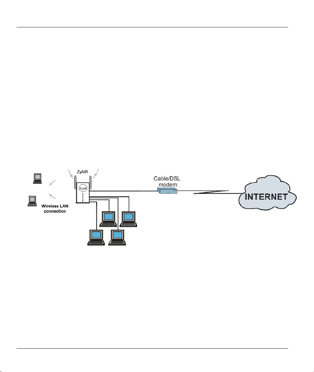
1.3.1 Broadband Internet Access via Cable or DSL modem.
A cable modem or DSL modem can be connected to the ZyAIR WAN port and up to four computers can be
connected to the ZyAIR LAN ports for super-fast broadband Internet access. Wireless clients also enjoy the
LAN connectivity to the Internet. The ZyAIR provides not only the high-speed Internet access but also a
complete solution to efficiently manage data traffic on your network.
Figure 1-1 Internet Access Application
1-4 Getting To Know Your ZyAIR
Page 25
ZyAIR B-2000 Wireless LAN Gateway with 4-Port Switch
Chapter 2
Hardware Installation and Initial Setup
This chapter describes the physical features of the ZyAIR and how to make cable connections.
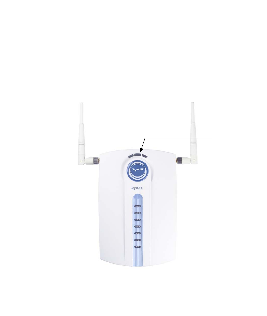
2.1 Front Panel LEDs of the ZyAIR
The LEDs on the front panel indicate the operational status of your ZyAIR
LINK LED
Figure 2-1 ZyAIR Front Panel
Hardware Installation and Initial Setup 2-1
Page 26

ZyAIR B-2000 Wireless LAN Gateway with 4-Port Switch
Table 2-1 Front Panel LED Description
LED COLOR STATUS DESCRIPTION
Green On The wireless card on the ZyAIR is working. LINK
Off The wireless card on the ZyAIR is not working.
ZyAIR
(WLAN
ACK)
LAN 1-4
WAN
SYS Green
Blue
Green
Orange
Green
Orange
On
(dim)
Breathing The ZyAIR is sending/receiving data through the wireless LAN.
On The ZyAIR has a successful 10Mb Ethernet connection.
Blinking The ZyAIR is sending/receiving data.
Off The ZyAIR does not have 10Mb Ethernet connection.
On The ZyAIR has a successful 100Mb Ethernet connection.
Blinking The ZyAIR is sending/receiving data.
Off The ZyAIR does not have 100Mb Ethernet connection.
On The ZyAIR has successful 10Mb WAN connection.
Blinking The ZyAIR is sending/receiving data.
Off The ZyAIR does not have 10Mb WAN connection.
On The ZyAIR has successful 100Mb WAN connection.
Blinking The ZyAIR is sending/receiving data.
Off The ZyAIR does not have 100Mb WAN connection.
On The ZyAIR is functioning properly.
Blinking The ZyAIR is rebooting.
Off The ZyAIR is not ready or has malfunctioned.
On The ZyAIR is receiving power. PWR Green
Off The ZyAIR is not receiving power.
The ZyAIR is ready, but is not sending/receiving data through the
wireless LAN.
2-2 Hardware Installation and Initial Setup
Page 27
ZyAIR B-2000 Wireless LAN Gateway with 4-Port Switch
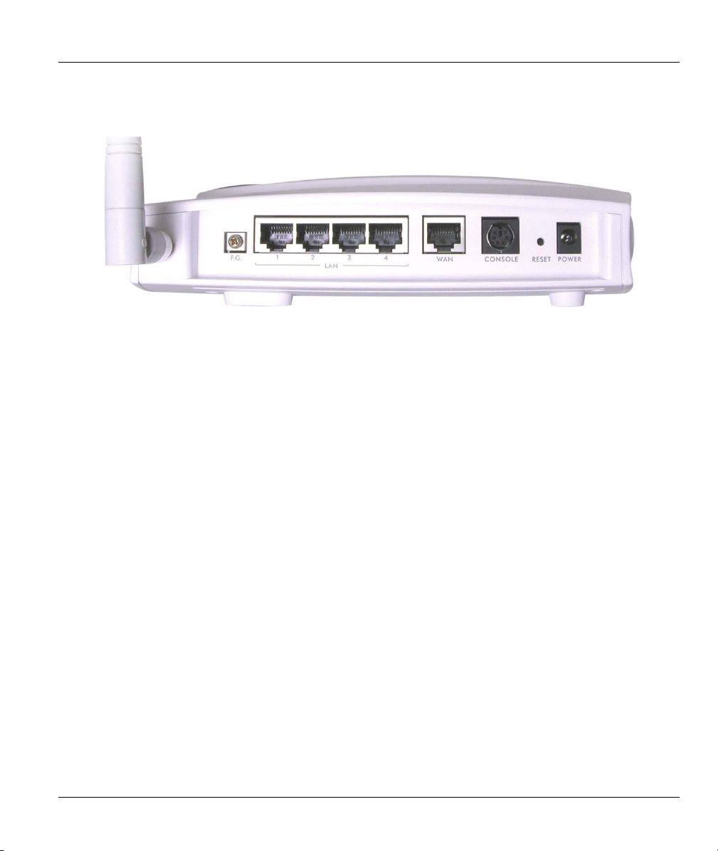
2.2 Side Panel and Connections of the ZyAIR
The following figure shows the side panel of your ZyAIR.
Figure 2-2 ZyAIR Side Panel and Connections
2.2.1 WAN Port
Connecting the ZyAIR to a Cable Modem
1. Connect the WAN port on the ZyAIR to the Ethernet port on your cable modem using the Ethernet
cable that came with your cable modem. The Ethernet port on a cable modem is sometimes labeled
"PC" or "Workstation".
2. Connect the coaxial cable from your cable service to the threaded coaxial cable connector on the back
of the cable modem.
Connecting the ZyAIR to a DSL Modem
Connect the WAN port on the ZyAIR to the Ethernet port on your DSL modem using the Ethernet cable
that came with your DSL modem.
2.2.2 Four LAN 10/100M Ports
Ethernet 10Base-T/100Base-T networks use Shielded Twisted Pair (STP) cable with RJ-45 connectors that
look like a bigger telephone plug with 8 pins. All LAN ports are auto-sensing, so you may use the crossover
cable provided or a straight-through Ethernet cable to connect your ZyAIR to a computer/external hub.
If you want to connect more than four computers to your ZyAIR, you must use an external hub. Connect a
LAN port on the ZyAIR to a port on the hub using a crossover Ethernet cable.
Hardware Installation and Initial Setup 2-3
Page 28

ZyAIR B-2000 Wireless LAN Gateway with 4-Port Switch
When the ZyAIR is on and properly connected to a computer or a hub, the
corresponding LAN LED on the front panel turns on.
2.2.3 Console Port
Use terminal emulator software on a computer for configuring your ZyAIR via the console port. Connect
the 7-pin end of the supplied console cable to the console port of the ZyAIR and the 9-pin female end to a
serial port (COM1, COM2 or other COM port) of your computer. See the section on Additional Installation
Requirements to configure the terminal emulator software to log in to the ZyAIR through the console port.
2.2.4 Restore Factory Defaults/Reset Button
Reset to the factory defaults by holding the RESET button in for about 5 seconds to restart the ZyAIR
.Refer to section 2.6 for information on the factory default values on your ZyAIR.
All custom settings will be lost once you reset to the default settings.
2.2.5 Power Port
Connect the power adapter to the port labeled POWER on the side panel of your ZyAIR which then
automatically turns on.
The ZyAIR will reboot if the supplied power is too low. This is a normal operation.
To avoid damage to the ZyAIR, make sure you use the correct power adapter.
Refer to the Power Adapter Specification Appendix for this information.
2.2.6 F.G. (Frame Ground)
Ground the ZyAIR by connecting a grounded wire to the F.G. terminal.
2.2.7 Antennas
The ZyAIR is equipped with two reverse SMA connectors and two detachable omni-directional 2dBi
antennas to provide clear radio signal between the wireless stations and the access points. Refer to the
Antenna Selection and Positioning Recommendations appendix for more information.
The following table shows the ZyAIR’s coverage in meters using the included antennas. The distance may
differ depending on the network environment.
2-4 Hardware Installation and Initial Setup
Page 29

ZyAIR B-2000 Wireless LAN Gateway with 4-Port Switch
Table 1-2 ZyAIR Wireless LAN Coverage
≈11 Mbps ≤ 5.5 Mbps
Indoor
Outdoor
ZyXEL offers several optional antennas to provide optimum coverage and performance for your ZyAIR.
Refer to the Quick Start Guide for instructions to attach the antennas to your ZyAIR.
50 m 80 m
200 m 300 m
2.3 Hardware Mounting Options
The ZyAIR may be placed on a flat surface or wall mounted.
In general, the best location to place the access point is at the center of your intended wireless coverage
area. For better performance, mount the ZyAIR in a high position free of obstructions.
Refer to the Quick Start Guide for hardware installation procedure.
2.4 Additional Installation Requirements
A computer with an IEEE 802.11b wireless LAN card or an Ethernet 10Base-T/100Base-T NIC.
To enable remote RADIUS authentication for wireless clients, you need
A wireless client computer running IEEE 802.1x-compliant software. Currently, this is offered in
Windows XP.
A network RADIUS server for remote user authentication and accounting.
A computer equipped with a web browser (with JavaScript enabled) and/or Telnet.
A computer equipped with communications software (for example, Hyper Terminal in Windows)
configured to the following parameters:
VT100 terminal emulation.
9600 baud rate.
Parity set to none, 8 data bits, 1 stop bit.
Flow control set to none.
• A cable/xDSL modem and an ISP account for Internet access.
Hardware Installation and Initial Setup 2-5
Page 30

ZyAIR B-2000 Wireless LAN Gateway with 4-Port Switch
2.5 ZyAIR Configuration
Configure your ZyAIR using:
Web configurator
SMT (System Management Terminal). Access the SMT via:
o LAN or WAN using Telnet
o Console port using terminal emulation software
2.5.1 Connect to Your ZyAIR Using the Web Configurator
Step 1. Make sure your computer IP address and the ZyAIR IP address are on the same subnet. Refer to
the TCP/IP appendix.
Step 2. Launch your web browser and enter 192.168.1.1 as the URL.
Step 3. In the Password field, type "1234". Click Login.
Step 4. Either enter a new password (and retype it to confirm) and click Apply or click Ignore.
Click the Help button for online web configurator HTML help.
2.5.2 Connect to your ZyAIR Using Telnet
The following procedure details how to telnet into your ZyAIR.
Step 1. Make sure your computer IP address and the ZyAIR IP address are on the same subnet. Refer to
the TCP/IP appendix.
Step 2. In Windows, click Start (usually in the bottom left corner), Run and then type “telnet
192.168.1.1” (the default IP address) and click OK.
Step 3. Enter 1234 in the Password field.
Step 4. After entering the password you will see the main menu.
2.5.3 Connect to Your ZyAIR Using the Console Port
Step 1. Connect the 7-pin male end of a console port cable to the port labelled CONSOLE on the
ZyAIR and the 9-pin female end to an avaliable serial port on your computer.
Step 2. Run the communications software and configure the communication parameteres as described
in the Additional Installation Requirements section.
Step 3. Turn on your ZyAIR and you should see the initial screen shown next.
2-6 Hardware Installation and Initial Setup
Page 31

ZyAIR B-2000 Wireless LAN Gateway with 4-Port Switch
Please note that if there is no activity for longer than five minutes (default timeout
period) after you log in, your ZyAIR will automatically log you out.
The remainder of this user’s guide shows you how to configure the ZyAIR for Internet access using SMT
screens through the console port. There are also some sections in this guide that focus on using Telnet to
configure the ZyAIR.
2.5.4 Initial Screen
When you turn on your ZyAIR, it performs several internal tests as well as line initialization. After the
initialization, the ZyAIR asks you to press [ENTER] to continue, as shown.
Copyright (c) 1994 - 2002 ZyXEL Communications Corp.
initialize ch =0, ethernet address: 00:A0:C5:00:15:37
initialize ch =1, ethernet address: 00:A0:C5:00:15:38
initialize ch =2, ethernet address: 00:A0:C5:00:15:37
Press ENTER to continue...
Figure 2-3 Power-On Display
2.5.5 Entering Password
The login screen appears after you press [ENTER], prompting you to enter the password, as shown next.
For your first login, enter the default password “1234”. As you type the password, the screen displays an
“x” for each character you type.
Please note that if there is no activity for longer than five minutes after you log in, your ZyAIR will
automatically log you out and will display a blank screen. If you see a blank screen, press [ENTER] to
display the login screen again.
Enter Password : xxxx
Figure 2-4 Login Screen
Hardware Installation and Initial Setup 2-7
Page 32

ZyAIR B-2000 Wireless LAN Gateway with 4-Port Switch
2.6 Resetting the ZyAIR
If you forget your password or cannot access the ZyAIR, you will need to reload the factory-default
configuration file. Uploading this configuration file replaces the current configuration file with the factorydefault configuration file. This means that you will lose all configurations that you had previously; the
password will be reset to “1234” and the LAN IP address to 192.168.1.1.
To obtain the default configuration file, download it from the ZyXEL FTP site, unzip it and save it in a
folder.
2.6.1 Methods of Restoring Factory-Defaults
You can erase the current configuration and restore factory defaults in three ways:
1. Transfer the configuration file to your ZyAIR using the SMT menus. See later in this User’s Guide for
more information on this.
2. Use the RESET button on the side panel of the ZyAIR to upload the default configuration file (hold
this button in for more than 3 seconds). Use this method for cases when the password or IP address of
the ZyAIR is not known.
3. Use the web configurator to restore defaults (see the web configurator HTML help)
All custom settings will be lost once you reset to the default settings.
2.6.2 ZyAIR SMT Menu Overview
The following figure gives you an overview of the various SMT menu screens of your ZyAIR.
2-8 Hardware Installation and Initial Setup
Page 33

ZyAIR B-2000 Wireless LAN Gateway with 4-Port Switch
Figure 2-5 ZyAIR SMT Menu Overview
Hardware Installation and Initial Setup 2-9
Page 34

ZyAIR B-2000 Wireless LAN Gateway with 4-Port Switch
2.7 Navigating the SMT Interface
The SMT (System Management Terminal) is the interface that you use to configure your ZyAIR.
Several operations that you should be familiar with before you attempt to modify the configuration are
listed in the table below.
Table 2-3 Main Menu Commands
OPERATION KEYSTROKE DESCRIPTION
Move down to
another menu
Move up to a
previous menu
Move to a “hidden”
menu
Move the cursor [ENTER] or
Entering
information
Required fields
N/A fields <N/A> Some of the fields in the SMT will show a <N/A>. This symbol
Save your
configuration
Exit the SMT Type 99, then press
[ENTER] To move forward to a submenu, type in the number of the desired
submenu and press [ENTER].
[ESC] Press [ESC] to move back to the previous menu.
Press [SPACE
BAR] to change No
to Yes then press
[ENTER].
[UP]/[DOWN] arrow
keys.
Type in or press
[SPACE BAR], then
press [ENTER].
<?>
[ENTER] Save your configuration by pressing [ENTER] at the message
[ENTER].
Fields beginning with “Edit” lead to hidden menus and have a
default setting of No. Press [SPACE BAR] once to change No to
Yes, then press [ENTER] to go to the “hidden” menu.
Within a menu, press [ENTER] to move to the next field. You can
also use the [UP]/[DOWN] arrow keys to move to the previous
and the next field, respectively.
You need to fill in two types of fields. The first requires you to type
in the appropriate information. The second allows you to cycle
through the available choices by pressing [SPACE BAR].
All fields with the symbol <?> must be filled in order to be able to
save the new configuration.
refers to an option that is Not Applicable.
“Press ENTER to confirm or ESC to cancel”. Saving the data on
the screen will take you, in most cases to the previous menu.
Type 99 at the main menu prompt and press [ENTER] to exit the
SMT interface.
After you enter the password, the SMT displays the main menu, as shown next.
2-10 Hardware Installation and Initial Setup
Page 35

ZyAIR B-2000 Wireless LAN Gateway with 4-Port Switch
ZyAIR B-2000 Main Menu
Getting Started
1. General Setup
2. WAN Setup
3. LAN Setup
4. Internet Access Setup
Advanced Applications
11. Remote Node Setup
12. Static Routing Setup
14. Dial-in User Setup
15. NAT Setup
Enter Menu Selection Number:_
Copyright (c) 1994 - 2002 ZyXEL Communications Corp.
Advanced Management
21. Filter Set Configuration
22. SNMP Configuration
23. System Password
24. System Maintenance
26. Schedule Setup
99. Exit
Figure 2-6 SMT Main Menu
The SMT menu continually improves and changes with new firmware upgrades. Check the release notes at
www.zyxel.com
to find the most recent upgrades and information.
2.7.1 System Management Terminal Interface Summary
Table 2-4 Main Menu Summary
# MENU TITLE DESCRIPTION
1 General Setup Use this menu to set up your general information.
2 WAN Use this menu to set up your WAN connection.
3 LAN Setup Use this menu to set up your LAN and WLAN connection.
4 Internet Access Setup A quick and easy way to set up an Internet connection.
11 Remote Node Setup Use this menu to set up the Remote Node for LAN-to-LAN connection,
including Internet connection.
12 Static Routing Setup Use this menu to set up static routes.
14 Dial-in User Setup Use this menu to set up local user profiles on the ZyAIR.
15 NAT Setup Use this menu to specify inside servers when NAT is enabled.
21 Filter Set Configuration Use this menu to set up filters to provide security, etc.
22 SNMP Configuration Use this menu to set up SNMP related parameters.
23 System Password Use this menu to change your password.
Hardware Installation and Initial Setup 2-11
Page 36

ZyAIR B-2000 Wireless LAN Gateway with 4-Port Switch
Table 2-4 Main Menu Summary
# MENU TITLE DESCRIPTION
24 System Maintenance This menu provides system status, diagnostics, software upload, etc.
26 Schedule Setup Use this menu to schedule outgoing calls.
99 Exit Use this to exit from SMT and return to a blank screen.
2.8 Changing the System Password
Change the ZyAIR default password by following the steps shown next.
Step 1. Enter 23 in the main menu to display Menu 23 - System Password as shown next.
Step 2. Type your existing system password in the Old Password field, for example “1234”, and press
[ENTER].
Menu 23 – System Password
Old Password= ****
New Password= ?
Retype to confirm= ?
Enter here to CONFIRM or ESC to CANCEL:
Figure 2-7 Menu 23 – System Password
Step 3. Type your new system password in the New Password field (up to 30 characters), and press
[ENTER].
Step 4. Re-type your new system password in the Retype to confirm field for confirmation and press
[ENTER].
Note that as you type a password, the screen displays an asterisk “*” for each character you type.
2.9 General Setup
Menu 1 – General Setup contains administrative and system-related information (shown next). The
System Name field is for identification purposes. However, because some ISPs check this name you should
enter your computer's "Computer Name".
• In Windows 95/98 click Start, Settings Control, Panel Network. Click the Identification tab,
note the entry for the Computer name field and enter it as the ZyAIR System Name.
2-12 Hardware Installation and Initial Setup
Page 37

ZyAIR B-2000 Wireless LAN Gateway with 4-Port Switch
In Windows 2000 click Start, Settings, Control Panel and then double-click System. Click the Network
Identification tab and then the Properties button. Note the entry for the Computer name field and enter it
as the ZyAIR System Name.
In Windows XP, click start, My Computer View system information and then click the Computer
Name tab. Note the entry in the Full computer name field and enter it as the ZyAIR System Name.
The Domain Name entry is what is propagated to the DHCP clients on the LAN. If you leave this blank,
the domain name obtained by DHCP from the ISP is used. While you must enter the host name (System
Name) on each individual computer, the domain name can be assigned from the ZyAIR via DHCP.
2.9.1 Dynamic DNS
Dynamic DNS (Domain Name System) allows you to update your current dynamic IP address with one or
many dynamic DNS services so that anyone can contact you (in NetMeeting, CU-SeeMe or other services).
You can also access your FTP server or Web site on your own computer using a DNS-like address (for
example, myhost.dhs.org, where myhost is a name of your choice) which will never change instead of using
an IP address that changes each time you reconnect. Your friends or relatives will always be able to call you
even if they don't know your IP address.
First of all, you need to have registered a dynamic DNS account with www.dyndns.org. This is for people
with a dynamic IP from their ISP or DHCP server that would still like to have a DNS name.
To use this service, you must register with the Dynamic DNS service provider. The Dynamic DNS service
provider will give you a password or key. The ZyAIR supports www.dyndns.org. You can apply to this
service provider for Dynamic DNS service.
DYNDNS Wildcard
Enabling the wildcard feature for your host causes *.yourhost.dyndns.org to be aliased to the same IP
address as yourhost.dyndns.org. This feature is useful if you want to be able to use, for example,
www.yourhost.dyndns.org and still reach your hostname.
2.9.2 Procedure To Configure Menu 1
Step 1. Enter 1 in the Main Menu to open Menu 1 – General Setup (shown next).
Menu 1 - General Setup
System Name= ?
Domain Name=
Edit Dynamic DNS= No
Press ENTER to Confirm or ESC to Cancel:
Figure 2-8 Menu 1 – General Setup
Hardware Installation and Initial Setup 2-13
Page 38

ZyAIR B-2000 Wireless LAN Gateway with 4-Port Switch
Step 2. Fill in the required fields. Refer to the table shown next for more information about these fields.
Table 2-5 General Setup Menu Fields
FIELD DESCRIPTION EXAMPLE
System Name Choose a descriptive name for identification purposes. This name can
ZyAIR
be up to 30 alphanumeric characters long. Spaces are not allowed, but
dashes “-” and underscores "_" are accepted.
Domain Name Enter the domain name (if you know it) here. If you leave this field blank,
the ISP may assign a domain name via DHCP. You can go to menu 24.8
zyxel.com.t
w
and type "sys domainname" to see the current domain name used by
your gateway.
If you want to clear this field just press the [SPACE BAR]. The domain
name entered by you is given priority over the ISP assigned domain
name.
Edit Dynamic DNS
Press [SPACE BAR] to select Yes and press [ENTER] to configure
No
Menu 1.1 – Configure Dynamic DNS (discussed next).
When you have completed this menu, press [ENTER] at the prompt “Press ENTER to Confirm…” to save
your configuration, or press [ESC] at any time to cancel.
2.9.3 Procedure to Configure Dynamic DNS
If you have a private WAN IP address, then you cannot use Dynamic DNS.
Step 1. To configure Dynamic DNS, go to Menu 1 – General Setup and select Yes in the Edit
Dynamic DNS field. Press [ENTER] to display Menu 1.1– Configure Dynamic DNS as
shown next.
Menu 1.1 - Configure Dynamic DNS
Press ENTER to Confirm or ESC to Cancel:
Service Provider= WWW.DynDNS.ORG
Active= Yes
DDNSType= DynamicDNS
Host=
EMAIL=
USER=
Password= ********
Enable Wildcard= No
Offline= N/A
Figure 2-9 Configure Dynamic DNS
2-14 Hardware Installation and Initial Setup
Page 39

ZyAIR B-2000 Wireless LAN Gateway with 4-Port Switch
Follow the instructions in the next table to configure Dynamic DNS parameters.
Table 2-6 Configure Dynamic DNS Menu Fields
FIELD DESCRIPTION EXAMPLE
Service Provider This is the name of your Dynamic DNS service provider. WWW.DynDNS.ORG
(default)
Active
DDNS Type Select the type of service that you are registered for from your
Host Enter the domain name assigned to your ZyAIR by your
EMAIL Enter your e-mail address. mail@mailserver
USER Enter your user name.
Password Enter the password assigned to you.
Enable Wildcard Your ZyAIR supports DYNDNS Wildcard. Press [SPACE BAR]
Offline
When you have completed this menu, press [ENTER] at the prompt “Press ENTER to Confirm…” to save
your configuration, or press [ESC] at any time to cancel.
Press [SPACE BAR] to select Yes and then press [ENTER] to
make dynamic DNS active.
Dynamic DNS service provider.
Dynamic DNS provider.
and then [ENTER] to select Yes to activate wildcard. This field
is N/A when you choose DDNS client as your service provider.
This option is available when CustomDNS is selected in the
DDNS Type field. Check with your Dynamic DNS service
provider to have traffic redirected to a URL (that you can
specify) while you are off line.
Yes
Dynamic DNS
(default)
me.dyndns.org
No
N/A
2.10 WAN Setup
The MAC address field allows users to configure the WAN port's MAC Address by either using the factory
default or cloning the MAC address from a computer on your LAN. Once it is successfully configured, the
address will be copied to the rom file (ZyNOS configuration file). It will not change unless you change the
setting or upload a different rom file.
ZyXEL recommends you clone the MAC address from a workstation on your LAN
even if your ISP does not require MAC address authentication.
Hardware Installation and Initial Setup 2-15
Page 40

ZyAIR B-2000 Wireless LAN Gateway with 4-Port Switch
From the main menu, enter 2 to display Menu 2-WAN Setup screen as shown.
Menu 2 - WAN Setup
MAC Address:
Assigned By= Factory default
IP Address= N/A
Press ENTER to Confirm or ESC to Cancel:
Figure 2-10 Menu 2 – WAN Setup
The following table describes the fields in this screen.
Table 2-7 WAN Setup Field Descriptions
FIELD DESCRIPTION EXAMPLE
MAC Address
Assigned By
Press [SPACE BAR] to select Factory default and press [ENTER] to
use the factory assigned MAC address.
Select IP address attached on LAN and enter the IP address in the
IP Address field below to clone the MAC address of the computer
on the Ethernet.
IP Address Enter the IP address of the computer whose MAC address you are
cloning. This field is available if you select IP address attached on
LAN in the Assigned By field.
Factory default
N/A
2.11 LAN Setup
This section describes how to configure the Ethernet using Menu 3 – LAN Setup. From the main menu,
enter 3 to display menu 3.
2-16 Hardware Installation and Initial Setup
Page 41

ZyAIR B-2000 Wireless LAN Gateway with 4-Port Switch
Menu 3 - LAN Setup
1. LAN Port Filter Setup
2. TCP/IP and DHCP Setup
5. Wireless LAN Setup
Enter Menu Selection Number:
Figure 2-11 Menu 3 – LAN Setup
Detailed explanation about the LAN Setup screens is given in the next chapter.
2.11.1 General Ethernet Port Filter Setup
This menu allows you to specify filter set(s) that you wish to apply to the Ethernet traffic. You seldom
need to filter Ethernet traffic; however, the filter sets may be useful to block certain packets, reduce traffic
and prevent security breaches.
Menu 3.1 - LAN Port Filter Setup
Input Filter Sets:
protocol filters=
device filters=
Output Filter Sets:
protocol filters=
device filters=
Press ENTER to Confirm or ESC to Cancel:
Figure 2-12 Menu 3.1 – General Ethernet Setup
If you need to define filters, please read the Filter Set Configuration chapter first, then return to this menu
to define the filter sets.
Hardware Installation and Initial Setup 2-17
Page 42

Page 43

ZyAIR B-2000 Wireless LAN Gateway with 4-Port Switch
Chapter 3
Internet Access
This chapter shows you how to configure the LAN and WAN of your ZyAIR for Internet access.
3.1 Factory Ethernet Defaults
The Ethernet parameters of the ZyAIR are preset in the factory with the following values:
1. Ethernet IP address of 192.168.1.1 with subnet mask of 255.255.255.0 (24 bits).
2. DHCP server enabled with 32 client IP addresses starting from 192.168.1.33.
These parameters should work for the majority of installations. If the parameters are satisfactory, you can
skip to TCP/IP Ethernet Setup and DHCP to enter the DNS server address(es) if your ISP gives you explicit
DNS server address(es). If you wish to change the factory defaults or to learn more about TCP/IP, please
read on.
3.2 LANs and WANs
A LAN (Local Area Network) is a computer network limited to the immediate area, usually the same
building or floor of a building. A WAN (Wide Area Network), on the other hand, is an outside connection
to another network or the Internet.
3.2.1 LANs, WANs and the ZyAIR
The actual physical connection determines whether the ZyAIR ports are LAN or WAN ports. There are two
separate IP networks, one inside, the LAN network; the other outside: the WAN network as shown next:
Internet Access 3-1
Page 44

ZyAIR B-2000 Wireless LAN Gateway with 4-Port Switch
Figure 3-1 LAN & WAN IPs
3.3 TCP/IP Parameters
3.3.1 IP Address and Subnet Mask
Like houses on a street that share a common street name, the computers on a LAN share one common
network number.
Where you obtain your network number depends on your particular situation. If the ISP or your network
administrator assigns you a block of registered IP addresses, follow their instructions in selecting the IP
addresses and the subnet mask.
If the ISP did not explicitly give you an IP network number, then most likely you have a single user account
and the ISP will assign you a dynamic IP address when the connection is established. If this is the case, it is
recommended that you select a network number from 192.168.0.0 to 192.168.255.0 (ignoring the trailing
zero) and you must enable the Single User Account feature of the ZyAIR. The Internet Assigned Number
Authority (IANA) reserved this block of addresses specifically for private use; please do not use any other
number unless you are told otherwise. Let’s say you select 192.168.1.0 as the network number; which
covers 254 individual addresses, from 192.168.1.1 to 192.168.1.154 (zero and 255 are reserved). In other
words, the first three numbers specify the network number while the last number identifies an individual
computer on that network.
The subnet mask specifies the network number portion of an IP address. Your ZyAIR will compute the
subnet mask automatically based on the IP address that you entered. You don’t need to change the subnet
mask computed by the ZyAIR unless you are instructed to do otherwise.
3-2 Internet Access
Page 45

ZyAIR B-2000 Wireless LAN Gateway with 4-Port Switch
3.3.2 Private IP Addresses
Every machine on the Internet must have a unique address. If your networks are isolated from the Internet,
for example, only between your two branch offices, you can assign any IP addresses to the hosts without
problems. However, the Internet Assigned Numbers Authority (IANA) has reserved the following three
blocks of IP addresses specifically for private networks:
10.0.0.0 — 10.255.255.255
172.16.0.0 — 172.31.255.255
192.168.0.0 — 192.168.255.255
You can obtain your IP address from the IANA, from an ISP or it can be assigned from a private network.
If you belong to a small organization and your Internet access is through an ISP, the ISP can provide you
with the Internet addresses for your local networks. On the other hand, if you are part of a much larger
organization, you should consult your network administrator for the appropriate IP addresses.
Regardless of your particular situation, do not create an arbitrary IP address;
always follow the guidelines above. For more information on address assignment,
please refer to RFC 1597, Address Allocation for Private Internets and RFC 1466,
Guidelines for Management of IP Address Space.
3.3.3 RIP Setup
RIP (Routing Information Protocol) allows a router to exchange routing information with other routers.
The RIP Direction field controls the sending and receiving of RIP packets. When set to:
1. Both - the ZyAIR will broadcast its routing table periodically and incorporate the RIP information that
it receives.
2. In Only - the ZyAIR will not send any RIP packets but will accept all RIP packets received.
3. Out Only - the ZyAIR will send out RIP packets but will not accept any RIP packets received.
4. None - the ZyAIR will not send any RIP packets and will ignore any RIP packets received.
The Version field controls the format and the broadcasting method of the RIP packets that the ZyAIR sends
(it recognizes both formats when receiving). RIP-1 is universally supported; but RIP-2 carries more
information. RIP-1 is probably adequate for most networks, unless you have an unusual network topology.
Both RIP-2B and RIP-2M sends the routing data in RIP-2 format; the difference being that RIP-2B uses
subnet broadcasting while RIP-2M uses multicasting.
Internet Access 3-3
Page 46

ZyAIR B-2000 Wireless LAN Gateway with 4-Port Switch
3.3.4 DHCP Configuration
DHCP (Dynamic Host Configuration Protocol) allows the individual clients (computers) to obtain the
TCP/IP configuration at start-up from a centralized DHCP server. The ZyAIR has built-in DHCP server
capability, enabled by default, which means it can assign IP addresses, an IP default gateway and DNS
servers to Windows 95, Windows NT and other systems that support the DHCP client. The ZyAIR can also
act as a surrogate DHCP server where it relays IP address assignment from the actual DHCP server to the
clients.
IP Pool Setup
The ZyAIR is pre-configured with a pool of 32 IP addresses starting from 192.168.1.33 to 192.168.1.64 for
the client machines. This leaves 31 IP addresses, 192.168.1.3 to 192.168.1.32 (excluding the ZyAIR itself
which has a default IP of 192.168.1.1) for other server machines, for example, server for mail, FTP, telnet,
web, etc., that you may have.
DNS Server Address
DNS (Domain Name System) is for mapping a domain name to its corresponding IP address and vice versa,
for example, the IP address of www.zyxel.com is 204.217.0.2. The DNS server is extremely important
because without it, you must know the IP address of a machine before you can access it. The DNS server
addresses that you enter in the DHCP setup are passed to the client machines along with the assigned IP
address and subnet mask.
There are two ways that an ISP disseminates the DNS server addresses. The first is for an ISP to tell a
customer the DNS server addresses, usually in the form of an information sheet, when s/he signs up. If your
ISP does give you the DNS server addresses, enter them in the DNS Server fields in DHCP Setup,
otherwise, leave them blank.
Some ISP’s choose to pass the DNS servers using the DNS server extensions of PPP IPCP (IP Control
Protocol) after the connection is up. If your ISP did not give you explicit DNS servers, chances are the DNS
servers are conveyed through IPCP negotiation. The ZyAIR supports the IPCP DNS server extensions
through the DNS proxy feature.
If the Primary and Secondary DNS Server fields in DHCP Setup are not specified, for instance, left as
0.0.0.0, the ZyAIR tells the DHCP clients that it itself is the DNS server. When a computer sends a DNS
query to the ZyAIR, the ZyAIR forwards the query to the real DNS server learned through IPCP and relays
the response back to the computer.
Please note that DNS proxy works only when the ISP uses the IPCP DNS server extensions. It does not
mean you can leave the DNS servers out of the DHCP setup under all circumstances. If your ISP gives you
explicit DNS servers, make sure that you enter their IP addresses in the DHCP Setup menu. This way, the
ZyAIR can pass the DNS servers to the computers and the computers can query the DNS server directly
without the ZyAIR’s intervention.
3-4 Internet Access
Page 47

ZyAIR B-2000 Wireless LAN Gateway with 4-Port Switch
3.4 IP Multicast
Traditionally, IP packets are transmitted in one of either two ways - Unicast (1 sender – 1 recipient) or
Broadcast (1 sender – everybody on the network). Multicast is a third way to deliver IP packets to a group
of hosts on the network - not everybody.
IGMP (Internet Group Multicast Protocol) is a session-layer protocol used to establish membership in a
multicast group - it is not used to carry user data. IGMP version 2 (RFC 2236) is an improvement over
version 1 (RFC 1112) but IGMP version 1 is still in wide use. If you would like to read more detailed
information about interoperability between IGMP version 2 and version 1, please see sections 4 and 5 of
RFC 2236. The class D IP address is used to identify host groups and can be in the range 224.0.0.0 to
239.255.255.255. The address 224.0.0.0 is not assigned to any group and is used by IP multicast computers.
The address 224.0.0.1 is used for query messages and is assigned to the permanent group of all IP hosts
(including gateways). All hosts must join the 224.0.0.1 group in order to participate in IGMP. The address
224.0.0.2 is assigned to the multicast routers group.
The ZyAIR supports both IGMP version 1 (IGMP-v1) and version 2 (IGMP-v2). At start up, the ZyAIR
queries all directly connected networks to gather group membership. After that, the ZyAIR periodically
updates this information. IP Multicasting can be enabled/disabled on the ZyAIR LAN and/or WAN
interfaces using menus 3.2 (LAN) and 11.3 (WAN). Select None to disable IP Multicasting on these
interfaces.
3.5 TCP/IP Ethernet and DHCP Setup
Use menu 3.2 to configure your ZyAIR for TCP/IP.
To edit menu 3.2, enter 3 from the main menu to display Menu 3-Ethernet Setup. When menu 3 appears,
press 2 and press [ENTER] to display Menu 3.2-TCP/IP and DHCP Ethernet Setup, as shown next
:
Internet Access 3-5
Page 48

ZyAIR B-2000 Wireless LAN Gateway with 4-Port Switch
Menu 3.2 - TCP/IP and DHCP Ethernet Setup
DHCP Setup:
DHCP= Server
Client IP Pool Starting Address= 192.168.1.33
Size of Client IP Pool= 32
Primary DNS Server= 0.0.0.0
Secondary DNS Server= 0.0.0.0
Remote DHCP Server= N/A
TCP/IP Setup:
IP Address= 192.68.1.1
IP Subnet Mask= 255.255.255.0
RIP Direction= Both
Version= RIP-1
Multicast= None
Edit IP Alias= No
Press ENTER to Confirm or ESC to Cancel:
Press Space Bar to Toggle.
First address in
the IP Pool
Size of the IP
Pool
IP addresses of
the DNS
servers
This is the IP
address of the
ZyAIR
Figure 3-2 Menu 3.2 – TCP/IP and DHCP Ethernet Setup
Follow the instructions in the following table on how to configure the DHCP fields.
Table 3-1 DHCP Ethernet Setup Menu Fields
FIELD DESCRIPTION EXAMPLE
DHCP Setup
If set to Server, your ZyAIR can assign IP addresses, an IP default
DHCP
gateway and DNS servers to Windows 95, Windows NT and other
systems that support the DHCP client.
If set to None, the DHCP server will be disabled.
If set to Relay, the ZyAIR acts as a surrogate DHCP server and
relays DHCP requests and responses between the remote server
and the clients. Enter the IP address of the actual, remote DHCP
server in the Remote DHCP Server in this case.
When DHCP is used, the following items need to be set:
Client IP Pool
Starting Address
This field specifies the first of the contiguous addresses in the IP
address pool.
Size of Client IP Pool This field specifies the size or count of the IP address pool. 32
Primary DNS Server
Secondary DNS
Enter the IP addresses of the DNS servers. The DNS servers are
passed to the DHCP clients along with the IP address and the subnet
mask.
Server
Server
(default)
192.168.1.33
3-6 Internet Access
Page 49

ZyAIR B-2000 Wireless LAN Gateway with 4-Port Switch
Table 3-1 DHCP Ethernet Setup Menu Fields
FIELD DESCRIPTION EXAMPLE
Remote DHCP
If Relay is selected in the DHCP field above then enter the IP
Server
address of the actual remote DHCP server here.
Follow the instructions in the following table to configure TCP/IP parameters for the Ethernet port.
Table 3-2 TCP/IP Ethernet Setup Menu Fields
FIELD DESCRIPTION EXAMPLE
TCP/IP Setup
IP Address Enter the (LAN) IP address of your ZyAIR in dotted decimal notation 192.168.1.1
IP Subnet Mask Your ZyAIR will automatically calculate the subnet mask based on the
IP address that you assign. Unless you are implementing subnetting,
use the subnet mask computed by the ZyAIR.
RIP Direction
Version
Multicast IGMP (Internet Group Multicast Protocol) is a session-layer protocol
SPACE BAR] to select the RIP direction. Choices are Both, In
Press [
Only, Out Only or None.
Press [SPACE BAR] to select the RIP version. Choices are RIP-1,
RIP-2B or RIP-2M.
used to establish membership in a Multicast group. The ZyAIR supports
both IGMP version 1(IGMP-v1) and version 2 (IGMP-v2). Press the
SPACE BAR] to enable IP Multicasting or select None to disable it.
[
255.255.255.0
Both
(default)
RIP-1
(default)
None
(default)
Edit IP Alias The ZyAIR supports three logical LAN interfaces via its single physical
Ethernet interface with the ZyAIR itself as the gateway for each LAN
network.
Press [
SPACE BAR] to select Yes and press [ENTER] to go to menu
3.2.1
When you have completed this menu, press [ENTER] at the prompt “Press ENTER to Confirm…” to save
your configuration, or press [ESC] at any time to cancel.
No
(default)
3.6 IP Alias
IP Alias allows you to partition a physical network into different logical networks over the same Ethernet
interface. The ZyAIR supports three logical LAN interfaces via its single physical Ethernet interface with
the ZyAIR itself as the gateway for each LAN network.
Internet Access 3-7
Page 50

ZyAIR B-2000 Wireless LAN Gateway with 4-Port Switch
Figure 3-3 Physical Network Figure 3-4 Partitioned Logical Networks
Use menu 3.2.1 to configure IP Alias on your ZyAIR.
3.6.1 IP Alias Setup
Use menu 3.2 to configure the first network. Move the cursor to Edit IP Alias field and press
[SPACE BAR] to choose Yes and press [ENTER] to configure the second and third network.
Menu 3.2 - TCP/IP and DHCP Setup
DHCP Setup:
DHCP= Server
Client IP Pool Starting Addres= 192.168.1.33
Size of Client IP Pool= 6
Primary DNS Server= 0.0.0.0
Secondary DNS Server= 0.0.0.0
Remote DHCP Server= N/A
TCP/IP Setup:
IP Address= 192.168.1.1
IP Subnet Mask= 255.255.255.0
RIP Direction= None
Version= N/A
Multicast= None
IP Policies=
Press ENTER to confirm or ESC to Cancel:
Edit IP Alias= Yes
Figure 3-5 Menu 3.2-TCP/IP and DHCP Setup
Press [ENTER] to display Menu 3.2.1-IP Alias Setup, as shown next.
3-8 Internet Access
Page 51

ZyAIR B-2000 Wireless LAN Gateway with 4-Port Switch
Menu 3.2.1 - IP Alias Setup
IP Alias 1= No
IP Address= N/A
IP Subnet Mask= N/A
RIP Direction= N/A
Version= N/A
Incoming protocol filters= N/A
Outgoing protocol filters= N/A
IP Alias 2= No
IP Address= N/A
IP Subnet Mask= N/A
RIP Direction= N/A
Version= N/A
Incoming protocol filters= N/A
Outgoing protocol filters= N/A
Enter here to CONFIRM or ESC to CANCEL:
Figure 3-6 Menu 3.2.1-IP Alias Setup
Follow the instructions in the table below to configure IP Alias parameters.
Table 3-3 IP Alias Setup Menu Fields
FIELD DESCRIPTION EXAMPLE
IP Alias
IP Address Enter the IP address of your ZyAIR in dotted decimal notation 192.168.1.1
IP Subnet Mask Your ZyAIR will automatically calculate the subnet mask based on
RIP Direction
Version
Incoming
Protocol Filters
Outgoing
Protocol Filters
Choose Yes to configure the LAN network for the ZyAIR. Yes
255.255.255.0
the IP address that you assign. Unless you are implementing
subnetting, use the subnet mask computed by the ZyAIR
Press [SPACE BAR] to select the RIP direction. Choices are None,
None
Both, In Only or Out Only.
Press [SPACE BAR] to select the RIP version. Choices are RIP-1,
RIP-1
RIP-2B or RIP-2M.
Enter the filter set(s) you wish to apply to the incoming traffic
between this node and the ZyAIR.
Enter the filter set(s) you wish to apply to the outgoing traffic between
this node and the ZyAIR.
When you have completed this menu, press [ENTER] at the prompt “Press ENTER to Confirm…” to save
your configuration, or press [
ESC] at any time to cancel.
Internet Access 3-9
Page 52

ZyAIR B-2000 Wireless LAN Gateway with 4-Port Switch
3.7 Encapsulation
Be sure to use the encapsulation method required by your ISP. The ZyAIR supports the following methods.
3.7.1 Ethernet
This encapsulation method is used when the WAN port is used as a regular Ethernet.
3.7.2 PPPoE
Point-to-Point Protocol over Ethernet (PPPoE) functions as a dial-up connection. PPPoE is an IETF Draft
standard specifying how a host personal computer interacts with a broadband modem (for example, xDSL,
cable, wireless, etc.) to achieve access to high-speed data networks. It preserves the existing Microsoft DialUp Networking experience and requires no new learning or procedures.
For the service provider, PPPoE offers an access and authentication method that works with existing access
control systems (for example, Radius). For the user, PPPoE provides a login and authentication method that
the existing Microsoft Dial-Up Networking software can activate, and therefore requires no new learning or
procedures for Windows users.
One of the benefits of PPPoE is the ability to let end users access one of multiple network services, a
function known as dynamic service selection. This enables the service provider to easily create and offer
new IP services for specific users.
Operationally, PPPoE saves significant effort for both the end user and ISP/carrier, as it requires no specific
configuration of the broadband modem at the customer site.
By implementing PPPoE directly on the ZyAIR (rather than individual computers), the computers on the
LAN do not need PPPoE software installed, since the Teledat Router 400 does that part of the task.
Furthermore, with SUA, all of the LAN's computers will have access. For more information on PPPoE,
please refer to the PPPoE Appendix.
3.7.3 PPTP
Point-to-Point Tunneling Protocol (PPTP) is a network protocol that enables transfer of data from a remote
client to a private server, creating a Virtual Private Network (VPN) using TCP/IP-based networks.
PPTP supports on-demand, multi-protocol, and virtual private networking over public networks, such as the
Internet. For more information on PPTP, please refer to the PPTP Appendix.
3-10 Internet Access
Page 53

ZyAIR B-2000 Wireless LAN Gateway with 4-Port Switch
3.8 IP Address Assignment
A static IP is a fixed IP that your ISP gives you. A dynamic IP is not fixed; the ISP assigns you a different
one each time. The Single User Account feature can be enabled or disabled if you have either a dynamic or
static IP. However the encapsulation method assigned influences your choices for IP Address.
3.9 Internet Access Configuration
Menu 4 allows you to enter the Internet Access information in one screen. Menu 4 is actually a simplified
setup for one of the remote nodes that you can access in menu 11. Before you configure your ZyAIR for
Internet access, you need to collect your Internet account information from your ISP and telephone
company.
Use the following table to record your Internet Account Information. Note that if you are using PPP or
PPPoE encapsulation, then the only ISP information you need is a login name and password.
Table 3-4 Internet Account Information
FIELD DESCRIPTION YOUR INFO
System Name Name of the ZyAIR (optional).
Service Name
(PPPoE)
Encapsulation Ethernet, PPPoE or PPTP
My Login Enter the login name assigned by your ISP (for
My Password Enter the password associated with your ISP assigned
Idle Timeout
(PPPoE or PPP)
IP Address Enter if your IP address is not dynamically assigned.
Enter the PPPoE service name if the ISP supplies one.
Enter “any” if the ISP does not assign you one.
PPP/PPPoE only).
My Login (for PPP/PPPoE only).
Enter the time lapse, in seconds, before you
automatically disconnect from the PPPoE or PPP
server.
Network Address
Translation
DNS Server
Address
Assignment
Full Feature, SUA Only or None.
Primary DNS server
Secondary DNS server
Enter when using RFC 1483 Encapsulation or a static
IP address.
Internet Access 3-11
Page 54

ZyAIR B-2000 Wireless LAN Gateway with 4-Port Switch
3.10 Internet Access Setup
From the main menu, type 4 to display Menu 4 – Internet Access Setup, as shown next.
Menu 4 - Internet Access Setup
ISP's Name= ChangeMe
Encapsulation= Ethernet
Service Type= Standard
My Login= N/A
My Password= N/A
Login Server= N/A
IP Address Assignment= Dynamic
IP Address= N/A
IP Subnet Mask= N/A
Gateway IP Address= N/A
Network Address Translation= SUA Only
Press ENTER to Confirm or ESC to Cancel:
Figure 3-7 Internet Access Setup
The following table contains instructions on how to configure your ZyAIR for Internet access.
Table 3-5 Internet Access Setup Menu Fields
FIELD DESCRIPTION EXAMPLE
ISP’s Name Enter the name of your Internet Service Provider. This information is
for identification purposes only.
Encapsulation
Press [SPACE BAR] to select the method of encapsulation used
by your ISP. Choices are PPPoE, PPP or Ethernet.
Service Type
This field is available if you select the Ethernet encapsulation.
Press [SPACE BAR] to select the service type then press [ENTER].
Choose a RoadRunner flavor if your ISP is using Time Warner's
RoadRunner; otherwise choose Standard. The User Name,
Password and Login Server fields are not applicable (N/A) for the
latter.
Choose from Standard, Telstra (RoadRunner Telstra or BigPond
authentication method), RR-Manager (RoadRunner Manager
authentication method) or RR-Toshiba (RoadRunner Toshiba
authentication method).
MyISP
Ethernet
Standard
3-12 Internet Access
Page 55

ZyAIR B-2000 Wireless LAN Gateway with 4-Port Switch
Table 3-5 Internet Access Setup Menu Fields
FIELD DESCRIPTION EXAMPLE
My Login
My Password Enter the password associated with the login name above. N/A
Login Server Enter the IP address of the login server in dotted decimal notation. 10.11.12.13
IP Address
Assignment
IP Address Enter the IP address supplied by your ISP if applicable. 10.11.12.20
IP Subnet Mask Your ZyAIR will automatically calculate the subnet mask based on
Gateway IP
Address
Network Address
Translation
Configure the My Login and My Password fields for PPP and
PPPoE encapsulation only. Enter the login name that your ISP gives
you. If you are using PPPoE encapsulation, then this field must be
of the form user@domain
service name.
Press [SPACE BAR] and then [ENTER] to select Static or
Dynamic address assignment.
the IP address that you entered. Unless you are implementing
subnetting, use the subnet mask computed by the ZyAIR.
Type the IP address of the gateway. The gateway is an immediate
neighbor of your ZyAIR that will forward the packet to the
destination. On the LAN, the gateway must be a router on the same
segment as your ZyAIR.
Press [SPACE BAR] and then [ENTER] to select None, SUA Only
or Full Feature. Please see the NAT Chapter for more details.
where domain identifies your PPPoE
N/A
Static
SUA Only
When you have completed this menu, press [ENTER] at the prompt “Press ENTER to Confirm…” to save
your configuration, or press [ESC] at any time to cancel.
If all your settings are correct your ZyAIR should connect automatically to the Internet. If the connection
fails, note the error message that you receive on the screen and take the appropriate troubleshooting steps.
3.11 Wireless LAN
3.11.1 Wireless LAN Parameters
Channel
The range of radio frequencies used by IEEE 802.11b wireless devices is called a channel. You can choose
the radio channel depending on your geographical area. Adjacent Access Points (APs) with overlapping
coverage areas should use different channels to reduce crosstalk. Crosstalk occurs when the radio signals
from access points overlap and interfere one another degrading performance.
Internet Access 3-13
Page 56

ZyAIR B-2000 Wireless LAN Gateway with 4-Port Switch
ESS ID
Extended Service Set (ESS) is defined as one or more access points (APs) acting as a bridge between a
wired LAN and the associated wireless clients. The ESS ID is a unique ID given to the APs and the wireless
clients that participate in the same wireless network. You can think the EES ID as being similar to a
workgroup name in a Microsoft network.
Wireless LANs can be as simple as two computers with wireless network interface cards (NICs)
communicating in a peer-to-peer network or as complex as a number of computers with wireless NICs
communicating through access points which bridge network traffic to the wired LAN.
The ESS ID provides minimum security for your network, see section on Wireless Security Setup for more
information.
RTS Threshold
The RTS (Request To Send) Threshold prevents the hidden node problem. Hidden node problem occurs
when two stations are within the range of the same access point, but are not within the range of each other.
The following figure illustrates the hidden node problem. Both stations (STA) are within the range of the
AP, however, they cannot hear each other. Therefore, they are considered as hidden nodes from each other.
When a station starts data transmission with the access point, it might not know that the other station is
already using the wireless medium. When these two stations send data at the same time, they might collide
when arriving simultaneously at the AP. The collision will most certainly result in a loss of messages for
both stations.
Figure 3-8 RTS Threshold
Thus, RTS Threshold mechanism provides a solution to prevent data collisions. When you enable RTS
Threshold on a possible hidden station, this station and its AP will use a Request to Send/Clear to Send
protocol (RTS/CTS). The station will send an RTS message to the AP, informing that it is going to transmit
the data. Upon receipt, the Access Point will respond with a CTS message to all stations within its range to
3-14 Internet Access
Page 57

ZyAIR B-2000 Wireless LAN Gateway with 4-Port Switch
notify all other stations to defer transmission. It will also confirm with the requesting station that the AP has
reserved it for the time frame of the requested transmission.
The RTS function will be activated if the packet size exceeds the value you set. It is highly recommended
that you set the value ranging from 0 to 2432.
Enabling the RTS Threshold causes redundant network overhead that could
negatively affect the throughput performance instead of providing a remedy.
Fragmentation Threshold
Fragmentation improves the efficiency when high traffic flows along in the wireless network.
WEP
As the first line of protection against wireless network intrusion, the ZyAIR provides the standard WEP
(Wired Equivalent Privacy) for data encryption. However, there may be a significant degradation of the
data throughput on the wireless link when WEP is enabled. See section on Wireless Security Setup for more
information about configuring WEP data encryption.
3.11.2 Wireless LAN Setup
Use menu 3.5 to set up your ZyAIR as the wireless access point. To edit menu 3.5, enter 3 from the main
menu to display Menu 3 – LAN Setup. When menu 3 appears, press 5 and then press [ENTER] to display
Menu 3.5 – Wireless LAN Setup as shown next.
Menu 3.5 - Wireless LAN Setup
ESSID= Wireless
Hide ESSID= No
Channel ID= CH01 2412MHz
RTS Threshold= 2432
Frag. Threshold= 2432
WEP= Disable
Default Key= N/A
Key1= N/A
Key2= N/A
Key3= N/A
Key4= N/A
Edit MAC Address Filter= No
Press ENTER to Confirm or ESC to Cancel:
Edit Roaming Configuration= Yes
Figure 3-9 Menu 3.5 - Wireless LAN Setup
The following table describes the fields in this screen.
Internet Access 3-15
Page 58

ZyAIR B-2000 Wireless LAN Gateway with 4-Port Switch
Table 3-6 Wireless LAN Setup Field Description
FIELD DESCRIPTION EXMAPLE
The ESSID (Extended Service Set IDentity) identifies the AP the wireless client
ESSID
Hide ESSID
Channel ID
RTS
Threshold
Fragment
Threshold
When you have completed this menu, press [ENTER] at the prompt “Press ENTER to confirm or ESC to
cancel” to save your configuration or press [ESC] to cancel and go back to the previous screen.
is to associate to. Wireless clients associating to the AP must have the same
ESSID. Enter a descriptive name up to 32 printable 7-bit ASCII characters.
Press [SPACE BAR] and select Yes to hide the ESSID in the outgoing beacon
frame so a station cannot obtain the ESSID through passive scanning.
Press [SPACE BAR] to select a channel. This allows you to set the operating
frequency/channel depending on your particular region.
Possible choices are CH01 2412MHz, CH02 2417MHz, CH03 2422MHz,
CH04 2427MHz, CH05 2432MHz, CH06 2437MHz, CH07 2442MHz, CH08
2447MHz, CH09 2452MHz, CH10 2457MHz or CH11 2462MHz.
RTS (Request To Send) threshold (number of bytes) enables RTS/CTS
handshake. Data with its frame size larger than this value will perform the
RTS/CTS handshake. Setting this attribute to be larger than the maximum
MSDU (MAC Service Data Unit) size turns off the RTS/CTS handshake.
Setting this attribute to zero turns on the RTS/CTS handshake. Enter a value
between 0 and 2432.
The threshold (number of bytes) for the fragmentation boundary for directed
messages. It is the maximum data fragment size that can be sent. Enter a
value between 256 and 2432.
Wireless
No
CH01
2412MHz
2432
2432
For WEP key configuration, refer to section on WEP Data Encryption.
3.11.3 Roaming
A wireless station is a computer with an IEEE 802.11b compliant wireless Network Interface Card (NIC).
An Access Point (AP) acts as a bridge between the wireless and wired networks. An AP creates its own
wireless coverage area. A wireless station can associate with a particular access point only if it is within the
access point’s coverage area.
In a network environment with multiple access points, wireless stations are able to switch from one access
point to another as they move between the coverage areas. This is roaming. As the wireless station moves
from place to place, it is responsible for choosing the most appropriate access point depending on the signal
strength, network utilization or other factors.
The roaming feature on the access points allows the access points to relay information about the wireless
stations to each other. When a wireless station moves from a coverage area to another, it scans and uses the
3-16 Internet Access
Page 59

ZyAIR B-2000 Wireless LAN Gateway with 4-Port Switch
signal of a new access point, which then informs the access points on the LAN about the change. The new
information is then propagated to the other access points on the LAN. An example is shown in Figure 3-10.
If the roaming feature is not enabled on the access points, information is not communicated between the
access points when a wireless station moves between coverage areas. The wireless station may not be able
to communicate with other wireless stations on the network and vice versa.
Figure 3-10 Roaming Example
The steps below describe the roaming process.
Step 1. As wireless station Y moves from the coverage area of access point AP 1 to that of acces point
AP 2, it scans and uses the signal of access point AP 2.
Step 2. Access point AP 2 acknowledges the pressence of wireless station Y and relays this
information to access point AP 1 through the wired LAN.
Step 3. Access point AP 1 updates the new position of wireless station .
Step 4. Wireless station Y sends a request to access point AP 2 for reauthentication.
3.11.4 Requirements for Roaming
The following requirements must be met in order for wireless stations to roam between the coverage areas.
1. All the access points must be on the same subnet and configured with the same ESSID.
2. If IEEE 802.1x user authentication is enabled and to be done locally on the access point, the new
access point must have the user profile for the wireless station.
Internet Access 3-17
Page 60

ZyAIR B-2000 Wireless LAN Gateway with 4-Port Switch
3. The adjacent access points should use different radio channels when their coverage areas overlap.
4. All access points must use the same port number to relay roaming information.
5. The access points must be connected to the Ethernet and be able to get IP addresses from a DHCP
server if using dynamic IP address assignment.
3.11.5 Enable the Roaming Feature on the ZyAIR
Enable the roaming feature if you have two or more ZyAIRs on the same subnet. Follow the steps below to
allow roaming on your ZyAIR.
Step 1. From the main menu, enter 3 to display Menu 3 – LAN Setup.
Step 2. Enter 5 to display Menu 3.5 – Wireless LAN Setup.
Menu 3.5 - Wireless LAN Setup
ESSID= Wireless
Hide ESSID= No
Channel ID= CH01 2412MHz
RTS Threshold= 2432
Frag. Threshold= 2432
WEP= Disable
Default Key= N/A
Key1= N/A
Key2= N/A
Key3= N/A
Key4= N/A
Edit MAC Address Filter= No
Press ENTER to Confirm or ESC to Cancel:
Edit Roaming Configuration= Yes
Figure 3-11 Wireless LAN Setup
Step 3. Move the cursor to the Edit Roaming Configuration field. Press [SPACE BAR] to select Yes
and then press [ENTER]. Menu 3.5.2 – Roaming Configuration displays as shown next.
Menu 3.5.2 - Roaming Configuration
Active= Yes
Port #= 16290
Press ENTER to Confirm or ESC to Cancel:
Figure 3-12 Menu 3.5.2 – Roaming Configuration
The following table describes the fields in this menu.
3-18 Internet Access
Page 61

ZyAIR B-2000 Wireless LAN Gateway with 4-Port Switch
Table 3-7 Roaming Configuration Field Descriptions
FIELD DESCRIPTION
Active
Port # Enter the port number to communicate roaming information between access points. The
When you have completed this menu, press [ENTER] at the prompt “Press ENTER to confirm or ESC to
cancel” to save your configuration or press [ESC] to cancel and go back to the previous screen.
Press [SPACE BAR] and then [ENTER] to select Yes to allow roaming on the ZyAIR Press
[SPACE BAR] and then [ENTER] to select Yes to enable roaming on the ZyAIR if you have
two or more ZyAIRs on the same subnet..
port number must be the same on all access points. The default is 16290. Make sure this
port is not used by other services.
Internet Access 3-19
Page 62

Advanced Applications
PPaarrtt IIII::
ADVANCED APPLICATIONS
This part shows how to configure Wireless Security, Remote Node, Remote Node TCP/IP and
NAT.
II
Page 63

Page 64

ZyAIR B-2000 Wireless LAN Gateway with 4-Port Switch
Chapter 4
Wireless LAN Security Setup
This chapter describes the types of security you can enable on the ZyAIR.
4.1 Levels of Security
Wireless security is vital to your network to protect wireless communication between wireless clients,
access points and other wireless.
The figure below shows the possible wireless security levels on your ZyAIR. The highest security level is
EAP (Extensible Authentication Protocol) authentication. It requires interaction with a RADIUS (Remote
Authentication Dial-In User Service) server either on the WAN or your LAN to provide authentication
service for wireless clients.
Figure 4-1 ZyAIR Wireless Security Levels
If you do not enable any wireless security on your ZyAIR, your network is accessible to any wireless
networking device that is within range.
4.2 Data Encryption with WEP
WEP encryption scrambles the data transmitted between the wireless clients and the access points to keep
network communications private. It encrypts unicast and multicast communications in a network. Both the
wireless clients and the access points must use the same WEP key for data encryption and decryption. For
wireless LAN setup, refer to section on Wireless LAN Setup.
Your ZyAIR allows you to configure up to four 64-bit or 128-bit WEP keys but only one key can be
enabled at any one time. Follow the steps below to configure and enable WEP encryption.
Wireless LAN Security Setup 4-1
Page 65

ZyAIR B-2000 Wireless LAN Gateway with 4-Port Switch
Step 1. From the main menu, enter 3 to display Menu 3 – Lan Setup.
Step 2. Enter 5 to display Menu 3.5 – Wireless LAN Setup.
Menu 3.5 - Wireless LAN Setup
ESSID= 432545
Hide ESSID= No
Channel ID= CH11 2462MHz
RTS Threshold= 2432
Frag. Threshold= 2432
Default Key= N/A
Key1= N/A
Key2= N/A
Key3= N/A
Key4= N/A
Edit MAC Address Filter= No
Edit Roaming Configuration= No
WEP= Disable
Figure 4-2 Wireless LAN Setup
The following table describes the WEP related fields in this screen. For wireless LAN field descriptions
refer to section on Wireless LAN Setup.
Table 4-1 Wireless LAN Setup Field Description
FIELD DESCRIPTION EXMAPLE
WEP (Wired Equivalent Privacy) provides data encryption to prevent unauthorized
Disable
wireless stations from accessing data transmitted over the wireless network.
WEP
Select Disable to allow wireless clients to communicate with the access points
without any data encryption.
1
Default
Key
Select 64-bit WEP or 128-bit WEP to enable data encryption.
Enter the key number (1 to 4) in this field. Only one key cab be enabled at any
one time.
If you chose 64-bit WEP in the WEP Encryption field, then enter any 5
characters (ASCII string) or 10 hexadecimal digits ("0-9", "A-F") preceded by 0x
for each key.
Key 1 to
Key 4
If you chose 128-bit WEP in the WEP Encryption field, then enter 13 characters
(ASCII string) or 26 hexadecimal digits ("0-9", "A-F") preceded by 0x for each key.
There are four data encryption keys to secure your data from eavesdropping by
unauthorized wireless users. The values for the keys must be set up exactly the
same on the access points as they are on the wireless client computers.
When you have completed this menu, press [ENTER] at the prompt “Press ENTER to confirm or ESC to
cancel” to save your configuration or press [ESC] to cancel and go back to the previous screen.
4-2 Wireless LAN Security Setup
Page 66

ZyAIR B-2000 Wireless LAN Gateway with 4-Port Switch
4.3 Network Authentication
Before a wireless client can communicate on your network through your ZyAIR, it must be authenticated
by the ZyAIR or your network.
4.3.1 EAP
EAP is an authentication protocol designed originally to run over PPP (Point-to-Point Protocol) frame in
order to support multiple types of user authentication. By using EAP to interact with an EAP-compatible
RADIUS server, the access point helps a wireless client and a RADIUS server to perform mutual
authentication.
4.3.2 RADIUS
RADIUS is based on a client-sever model that supports authentication, authorization and accounting. The
access point is the client and the server is the RADIUS server. The RADIUS server handles the following
tasks:
• Authentication
Determines the identity of the users.
• Authorization
Determines the network services available to authenticated users once they are connected to the
network.
• Accounting
Keeps track of the client’s network activity.
RADIUS is a simple package exchange in which your ZyAIR acts as a message relay between the wireless
client and the network RADIUS server.
Types of RADIUS Messages
The following types of RADIUS messages are exchanged between the access point and the RADIUS server
for user authentication:
• Access-Request
Sent by an access point requesting authentication.
• Access-Reject
Sent by a RADIUS server rejecting access.
Wireless LAN Security Setup 4-3
Page 67

ZyAIR B-2000 Wireless LAN Gateway with 4-Port Switch
• Access-Accept
Sent by a RADIUS server allowing access.
• Access-Challenge
Sent by a RADIUS server requesting more information in order to allow access. The access point
sends a proper response from the user and then sends another Access-Request message.
The following types of RADIUS messages are exchanged between the access point and the RADIUS server
for user accounting:
• Accounting-Request
Sent by the access point requesting accounting.
• Accounting-Response
Sent by the RADIUS server to indicate that it has started or stopped accounting.
In order to ensure network security, the access point and the RADIUS server use a shared secret key, which
is a password, they both know. The key is not sent over the network. In addition to the shared key,
password information exchanged is also encrypted to protect the network from unauthorized access.
4.3.3 Sequence for EAP Authentication
The following figure shows the authentication steps when you enable EAP and specify a RADIUS server on
your access point.
Figure 4-3 Sequence for EAP Authentication
The steps below describe how the IEEE 802.1X EAP authentication works.
Step 1. The wireless client sents a “request” message to the ZyAIR..
Step 2. The ZyAIR sends a “request” message to the wireless client for identity information.
Step 3. The wireless client replies with the password and username information.
Step 4. The ZyAIR receives the message and repackets this information into an Access-Request
package which is then sent to the remote RADIUS server (or the Authentication server).
4-4 Wireless LAN Security Setup
Page 68

ZyAIR B-2000 Wireless LAN Gateway with 4-Port Switch
Step 5. The RADIUS server checks the user information against its user profile database and sends an
“accept” or a “deny” packet to ZyAIR.
Step 6. When ZyAIR receives the “accept” package, the client port is placed into an authorized state
and traffic is allowed to proceed. Otherwise, no traffic is allowed.
4.3.4 Enable EAP Authentication on Your ZyAIR
Follow the steps below to enable EAP authentication on your ZyAIR.
Step 1. From the main menu, enter 23 to display Menu23 – System Security.
Step 2. Enter 4 to display Menu 23.4 – System Security – IEEE802.1X.
Menu 23 - System Security
1. Change Password
2. RADIUS Server
4. IEEE802.1X
Figure 4-4 Menu 23 – System Security
Menu 23.4 - System Security - IEEE802.1X
Authentication Control= Force Authorized
ReAuthentication Timer (in second)= N/A
Press ENTER to Confirm or ESC to Cancel:
Figure 4-5 Menu 23.4- System Security – IEEE802.1X
The following table describes the fields in this screen.
Table 4-2 IEEE802.1X System Security Field Descriptions
FIELD DESCRIPTION
Authentication
Control
Press [SPACE BAR] to select from Forced Authorized, Forced Unauthorized or
Auto. The default is Forced Authorized.
Select Auto to authenticate all wireless clients.
Select Force Authorized to allow any user access to your wireless network without
authentication.
Select Force UnAuthorized to deny all user access to your wireless network.
Wireless LAN Security Setup 4-5
Page 69

ZyAIR B-2000 Wireless LAN Gateway with 4-Port Switch
Table 4-2 IEEE802.1X System Security Field Descriptions
FIELD DESCRIPTION
ReAuthentication Timer
(in seconds)
Specify the time interval between the RADIUS server’s authentication checks of
wireless users connected to the network.
This field is activated only when you select Auto authentication control. The default
time interval is 1800 seconds.
When you have completed this menu, press [ENTER] at the prompt “Press ENTER to confirm or ESC to
cancel” to save your configuration or press [ESC] to cancel and go back to the previous screen.
Once you enable the EAP authentication, you need to specify the external RADIUS server or create local
user accounts for authentication.
4.3.5 Configuring External RADIUS Server
From Menu 23- System Security, enter 2 to display Menu 23.2 - System Security-RADIUS Server as
shown next.
Menu 23.2 - System Security - RADIUS Server
Authentication Server:
Active= No
Server Address= ?
Port #= 1812
Key= ?
Accounting Server:
Active= No
Server Address= ?
Port #= 1813
Key= ?
Figure 4-6 Menu 23.2 System Security - External Server
The following table describes the fields in this screen.
Table 4-3 Menu 23.2 System Security - External Server Field Description
FIELD DESCRIPTION EXAMPLE
Authentication Server
Active
Press [SPACE BAR] to select Yes and press [ENTER] to enable
user authentication through an external authentication server.
Select No to enable user authentication using the local user
profile on the ZyAIR.
No
4-6 Wireless LAN Security Setup
Page 70

ZyAIR B-2000 Wireless LAN Gateway with 4-Port Switch
Table 4-3 Menu 23.2 System Security - External Server Field Description
FIELD DESCRIPTION EXAMPLE
Server Address Enter the IP address of the external authentication server in
dotted decimal notation.
Port The default port of the RADIUS server for authentication is
1812.
You need not change this value unless your network
administrator instructs you to do so with additional information.
Key Specify a password (up to 31 alphanumeric characters) as the
key to be shared between the external authentication server and
the access points.
The key is not sent over the network. This key must be the
same on the external authentication server and ZyAIR.
Accounting Server
Active
Server Address Enter the IP address of the external accounting server in dotted
When you have completed this menu, press [ENTER] at the prompt “Press ENTER to confirm or ESC to
cancel” to save your configuration or press [ESC] to cancel and go back to the previous screen.
Press [SPACE BAR] to select Yes and press [ENTER] to enable
user authentication through an external accounting server.
decimal notation.
The default port of the RADIUS server for accounting is 1813.
Port
You need not change this value unless your network
administrator instructs you to do so with additional information.
Key Specify a password (up to 31 alphanumeric characters) as the
key to be shared between the external accounting server and
the access points.
The key is not sent over the network. This key must be the
same on the external accounting server and ZyAIR.
10.11.12.13
1812
No
10.11.12.13
1813
4.4 Creating User Accounts on the ZyAIR
By storing user profiles locally, your ZyAIR is able to authenticate wireless users without interacting with a
network RADIUS server.
Follow the steps below to set up user profiles on your ZyAIR.
Step 1. From the main menu, enter 14 to display Menu 14 - Dial-in User Setup.
Wireless LAN Security Setup 4-7
Page 71

ZyAIR B-2000 Wireless LAN Gateway with 4-Port Switch
Menu 14 - Dial-in User Setup
1. ________ 9. ________ 17. ________ 25. ________
2. ________ 10. ________ 18. ________ 26. ________
3. ________ 11. ________ 19. ________ 27. ________
4. ________ 12. ________ 20. ________ 28. ________
5. ________ 13. ________ 21. ________ 29. ________
6. ________ 14. ________ 22. ________ 30. ________
7. ________ 15. ________ 23. ________ 31. ________
8. ________ 16. ________ 24. ________ 32. ________
Enter Menu Selection Number:
Figure 4-7 Menu 14- Dial-in User Setup
Step 2. Type a number and press [ENTER] to edit the user profile.
User Name= test
Active= Yes
Password= ********
Press ENTER to Confirm or ESC to Cancel:
Menu 14.1 - Edit Dial-in User
Figure 4-8 Menu 14.1- Edit Dial-in User
The following table describes the fields in this screen.
Table 4-4 Menu 14.1- Edit Dial-in User Field Description
FIELD DESCRIPTION
User Name Enter a username up to 31 alphanumeric characters long for this user profile.
Active
Press [SPACE BAR] to select Yes and press [ENTER] to enable the user profile.
Password Enter a password up to 31 characters long for this user profile.
When you have completed this menu, press [ENTER] at the prompt “Press ENTER to confirm or ESC to
cancel” to save your configuration or press [ESC] to cancel and go back to the previous screen.
4.5 MAC Address Filtering
Your ZyAIR checks the MAC address of the wireless client device against a list of allowed or denied MAC
addresses. However, intruders could fake allowed MAC addresses so MAC-based authentication is less
secure than EAP authentication.
4-8 Wireless LAN Security Setup
Page 72

ZyAIR B-2000 Wireless LAN Gateway with 4-Port Switch
Follow the steps below to create the MAC address table on your ZyAIR.
Step 1. From the main menu, enter 3 to open Menu 3 – LAN Setup.
Step 2. Enter 5 to display Menu 3.5 – Wireless LAN Setup.
ESSID= 432545
Hide ESSID= No
Channel ID= CH11 2462MHz
RTS Threshold= 2432
Frag. Threshold= 2432
WEP= Disable
Default Key= N/A
Key1= N/A
Key2= N/A
Key3= N/A
Key4= N/A
Edit Roaming Configuration= No
Menu 3.5 - Wireless LAN Setup
Edit MAC Address Filter= No
Press ENTER to Confirm or ESC to Cancel:
Figure 4-9 Menu 3.5 – Wireless LAN Setup
Step 3. In the Edit MAC Address Filtering field, press [SPACE BAR] to select Yes and press
[ENTER]. Menu 3.5.1 – WLAN MAC Address Filter displays as shown next.
Menu 3.5.1 - WLAN MAC Address Filter
Active= No
Filter Action= Allowed Association
MAC Address Filter
Address 1= 00:00:00:00:00:00
Address 2= 00:00:00:00:00:00
Address 3= 00:00:00:00:00:00
Address 4= 00:00:00:00:00:00
Address 5= 00:00:00:00:00:00
Address 6= 00:00:00:00:00:00
Address 7= 00:00:00:00:00:00
Address 8= 00:00:00:00:00:00
Address 9= 00:00:00:00:00:00
Address 10= 00:00:00:00:00:00
Address 11= 00:00:00:00:00:00
Address 12= 00:00:00:00:00:00
Enter here to CONFIRM or ESC to CANCEL:
Figure 4-10 Menu 3.5.1 – WLAN MAC Address Filter
The following table describes the fields in this menu.
Wireless LAN Security Setup 4-9
Page 73

ZyAIR B-2000 Wireless LAN Gateway with 4-Port Switch
Table 4-5 MAC Address Filter Field Description
FIELD DESCRIPTION
Active
Filter Action
MAC Address Filter
Address 1..12
When you have completed this menu, press [ENTER] at the prompt “Press ENTER to confirm or ESC to
cancel” to save your configuration or press [ESC] to cancel and go back to the previous screen.
To enable MAC address filtering, press [SPACE BAR] to select Yes and press [ENTER].
Define the filter action for the list of MAC addresses in the MAC address filter table.
To deny access to the ZyAIR, press [SPACE BAR] to select Deny Association and press
[ENTER]. MAC addresses not listed will be allowed to access the router.
The default action, Allowed Association, permits association with the ZyAIR. MAC
addresses not listed will be denied access to the router.
Enter the MAC addresses (in XX:XX:XX:XX:XX:XX format) of the client computers that are
allowed or denied access to the ZyAIR in these address fields.
4-10 Wireless LAN Security Setup
Page 74

ZyAIR B-2000 Wireless LAN Gateway with 4-Port Switch
Chapter 5
Remote Node Configuration
This chapter shows you how to set up remote nodes on the WAN side.
A remote node is required for placing calls to a remote gateway. A remote node represents both the remote
gateway and the network behind it across a WAN connection. When you use menu 4 to set up Internet
access, you are configuring one of the remote nodes.
5.1 Remote Node Profile
Use Menu 11-Remote Node Profile to setup the remote node.
From the main menu, enter 11 to display Menu 11-Remote Node Profile as shown in Figure 5-1.
5.1.1 Encapsulation Scenarios
For Internet access you should use the encapsulation used by your ISP.
Nailed-Up Connection (PPPoE/PPTP)
A nailed-up connection is a dial-up line where the connection is always up regardless of traffic demand.
The ZyAIR does two things when you specify a nailed-up connection. The first is that idle timeout is
disabled. The second is that the ZyAIR will try to bring up the connection when turned on and whenever the
connection is down. A nailed-up connection can be very expensive for obvious reasons.
Do not specify a nailed-up connection unless your telephone company offers flat-rate service or you need a
constant connection and the cost is of no concern.
Remote Node Configuration 5-1
Page 75

ZyAIR B-2000 Wireless LAN Gateway with 4-Port Switch
Menu 11.1 - Remote Node Profile
Rem Node Name= ChangeMe Route= IP
Active= Yes
Encapsulation= PPTP Edit IP= No
Service Type= Standard Telco Option:
Service Name= N/A Allocated Budget(min)= 0
Outgoing: Period(hr)= 0
My Login= Schedules=
My Password= ******** Nailed-Up Connection= No
Authen= CHAP/PAP
PPTP: Session Options:
My IP Addr= Edit Filter Sets= No
My IP Mask= Idle Timeout(sec)= 100
Server IP Addr=
Connection ID/Name=
Press ENTER to Confirm or ESC to Cancel:
Figure 5-1 Menu 11.1 - Remote Node Profile
In Menu 11.1 – Remote Node Profile, fill in the fields as described in the following table.
Table 5-1 Remote Node Profile Menu Fields
FIELD DESCRIPTION EXAMPLE
Rem Node Name Type a unique, descriptive name of up to eight characters for this
node.
Active
Encapsulation
Service Type Press [SPACE BAR] and then [ENTER] to select the service type.
Service Name
Press [SPACE BAR] and then [ENTER] to select No to deactivate
this node. Inactive nodes are displayed with a minus sign “–“ in
SMT menu 11.
Press [SPACE BAR] to select from Ethernet, PPPoE or PPTP and
press [ENTER].
Choose a RoadRunner flavor if your ISP is using Time Warner's
RoadRunner; otherwise choose Standard. The User Name,
Password and Login Server IP Address fields are not applicable
(N/A) for the latter.
Choose from Standard, Telstra (RoadRunner Telstra or BigPond
authentication method), RR-Manager (RoadRunner Manager
authentication method) or RR-Toshiba (RoadRunner Toshiba
authentication method).
When using PPPoE encapsulation, type the name of your PPPoE
service here.
ChangeMe
Yes
(default)
Ethernet
Standard
N/A
5-2 Remote Node Configuration
Page 76

ZyAIR B-2000 Wireless LAN Gateway with 4-Port Switch
Table 5-1 Remote Node Profile Menu Fields
FIELD DESCRIPTION EXAMPLE
Outgoing:
My Login
My Password Type the password assigned by your ISP when the ZyAIR calls this
Authen
PPTP:
My IP Address Type the (static) IP address assigned to you by your ISP in dotted
My IP Mask Type the subnet mask of the PPTP server.
Server IP Address Type the IP address of the PPTP server in dotted decimal notation.
Connection
ID/Name
Route
Edit IP
Telco Option:
Allocated
Budget (min)
Type the login name assigned by your ISP when the ZyAIR calls
this remote node.
remote node.
This field sets the authentication protocol used for outgoing calls.
Options for this field are:
CHAP/PAP – Your ZyAIR will accept either CHAP or PAP when
requested by this remote node.
CHAP – accept CHAP (Challenge Handshake Authentication
Protocol) only.
PAP – accept PAP (Password Authentication Protocol) only.
decimal notation.
Enter the connection ID or connection name in this field. It must
follow the "c:id" and "n:name" format. For example, C:12 or N:My
ISP.
This field is optional and depends on the requirements of your
xDSL modem.
This field determines the protocol used in routing. Options are IP
and None.
Press [SPACE BAR] to select Yes and press [ENTER] to display
Menu 11.3 – Remote Node Network Layer Options.
Telco Option is available only for PPTP or PPPoE encapsulation.
This sets a ceiling for outgoing call time for this remote node. The
default for this field is 0 meaning no budget control.
PAP
10.11.12.13
(default)
No
(default)
IP
0
Remote Node Configuration 5-3
Page 77

ZyAIR B-2000 Wireless LAN Gateway with 4-Port Switch
Table 5-1 Remote Node Profile Menu Fields
FIELD DESCRIPTION EXAMPLE
Period (hr) This field is the time period that the budget should be reset. For
example, if we are allowed to call this remote node for a maximum
of 10 minutes every hour, then the Allocated Budget is (10
minutes) and the Period (hr) is 1 (hour).
Schedule
Nailed up
Connection
Session Options
Edit Filter Sets
Idle Timeout (sec) Type the number of seconds (0-9999) that can elapse when the
When you have completed this menu, press [ENTER] at the prompt “Press ENTER to confirm or ESC to
cancel” to save your configuration or press [ESC] to cancel and go back to the previous screen.
This field is only applicable for PPPoE and PPPTP encapsulation.
You can apply up to four schedule sets here. For more details
please refer to the Call Schedule Setup chapter.
This field is only applicable for PPPoE and PPTP encapsulation.
This field specifies if you want to make the connection to this
remote node a nailed-up connection. More details are given earlier
in this section.
Use [SPACE BAR] to choose Yes and press [ENTER] to open
menu 11.5 to edit the filter sets. See the Remote Node Filter
section for more details.
ZyAIR is idle (there is no traffic going to the remote node), before
the ZyAIR automatically disconnects the remote node. 0 means
that the session will not timeout.
This field is available only for PPTP or PPPoE encapsulations.
0
(default)
No
(default)
100
(default)
5.1.2 Outgoing Authentication Protocol
For obvious reasons, you should employ the strongest authentication protocol possible. However, some
vendors’ implementation includes specific authentication protocol in the user profile. It will disconnect if
the negotiated protocol is different from that in the user profile, even when the negotiated protocol is
stronger than specified. If the peer disconnects right after a successful authentication, make sure that you
specify the correct authentication protocol when connecting to such an implementation.
5.1.3 Remote Node Setup
For the TCP/IP parameters, perform the following steps to edit Menu 11.3 - Remote Node Network Layer
Options.
5-4 Remote Node Configuration
Page 78

ZyAIR B-2000 Wireless LAN Gateway with 4-Port Switch
Move the cursor to the Edit IP field, press [SPACE BAR] to select Yes, then press [ENTER] to display
Menu 11.3 – Remote Node Network Layer Options shown below.
Menu 11.3 - Remote Node Network Layer Options
IP Address Assignment= Static
Rem IP Addr= 0.0.0.0
Rem Subnet Mask= 0.0.0.0
My WAN Addr= 0.0.0.0
Network Address Translation= None
Metric= 1
Private= No
RIP Direction= None
Version= N/A
Multicast= None
Enter here to CONFIRM or ESC to CANCEL:
Figure 5-2 Remote Node Network Layer Options
The next table explains fields in Menu 11.3
- Remote Node Network Layer Options.
Table 5-2 Remote Node Network Layer Options
FIELD DESCRIPTITON EXAMPLE
IP Address
Assignment
Press [SPACE BAR] and then [ENTER] to select Dynamic if the remote
node is using a dynamically assigned IP address or Static if it is using a
Static
static (fixed) IP address. You will only be able to configure this in the
ISP node (also the one you configure in menu 4), all other nodes are
set to Static.
Rem IP Addr This is the IP address you entered in the previous menu.
Rem Subnet
Type the subnet mask assigned to the remote node.
Mask
My WAN Addr Some implementations, especially UNIX derivatives, require separate
IP network numbers for the WAN and LAN links and each end to have a
unique address within the WAN network number. In that case, type the
IP address assigned to the WAN port of your ZyAIR.
Network
Address
Press [SPACE BAR] and then [ENTER] to select Full Feature if you
have multiple public WAN IP addresses for your ZyAIR.
Full
Feature
Translation
Remote Node Configuration 5-5
Page 79

ZyAIR B-2000 Wireless LAN Gateway with 4-Port Switch
Table 5-2 Remote Node Network Layer Options
FIELD DESCRIPTITON EXAMPLE
Select SUA Only if you have just one public WAN IP address for your
ZyAIR. The SMT uses Address Mapping Set 255 (menu 15.1 - see
section 6.3.1).
Select None to disable NAT.
Metric The metric represents the “cost” of transmission for routing purposes.
IP routing uses hop count as the cost measurement, with a minimum of
1 for directly connected networks. Type a number that approximates the
cost for this link. The number need not be precise, but it must be
between 1 and 15. In practice, 2 or 3 is usually a good number.
Private This determines if the ZyAIR will include the route to this remote node
in its RIP broadcasts. If set to Yes, this route is kept private and not
included in RIP broadcast. If No, the route to this remote node will be
propagated to other hosts through RIP broadcasts.
RIP Direction Press [SPACE BAR] and then [ENTER] to select the RIP Direction.
Options are Both, In Only, Out Only or None.
Version Press [SPACE BAR] and then [ENTER] to select the RIP version.
Options are RIP-1, RIP-2B or RIP-2M.
Multicast
When you have completed this menu, press [ENTER] at the prompt “Press ENTER to confirm or ESC to
cancel” to save your configuration or press [ESC] to cancel and go back to the previous screen.
IGMP-v1 sets IGMP to version 1, IGMP-v2 sets IGMP to version 2 and
None disables IGMP.
2
No
None
RIP-1
None
5.2 Remote Node Filter
Move the cursor to the Edit Filter Sets field in menu 11.1, then press [SPACE BAR] to select Yes. Press
[ENTER] to display Menu 11.5 - Remote Node Filter.
Use Menu 11.5 - Remote Node Filter to specify the filter set(s) to apply to the incoming and outgoing
traffic between this remote node and the ZyAIR and also to prevent certain packets from triggering calls.
You can specify up to 4 filter sets separated by comma, for example, 1, 5, 9, 12, in each filter field.
Note that spaces are accepted in this field.
5-6 Remote Node Configuration
Page 80

ZyAIR B-2000 Wireless LAN Gateway with 4-Port Switch
Input Filter Sets:
protocol filters= 1, 2, 3
device filters=
Output Filter Sets:
protocol filters=
device filters=
Enter here to CONFIRM or ESC to CANCEL:
Menu 11.5 - Remote Node Filter
Figure 5-3 Menu 11.5 - Remote Node Filter (Ethernet Encapsulation )
Menu 11.5 - Remote Node Filter
Enter here to CONFIRM or ESC to CANCEL:
Input Filter Sets:
protocol filters=
device filters=
Output Filter Sets:
protocol filters= 1
device filters=
Call Filter Sets:
protocol filters=
device filters=
Figure 5-4 Menu 11.5 - Remote Node Filter (PPTP or PPPoE Encapsulation)
5.2.1 IP Static Route Setup
Static routes tell the ZyAIR routing information that it cannot learn automatically through other means. This
can arise in cases where RIP is disabled on the LAN or a remote network is beyond the one that is directly
connected to a remote node.
Each remote node specifies only the network to which the gateway is directly connected and the ZyAIR has
no knowledge of the networks beyond. For instance, the ZyAIR knows about network N2 in the following
figure through remote node Router 1. However, the ZyAIR is unable to route a packet to network N3
because it does not know that there is a route through remote node Router 1 (via Router 2). The static routes
allow you to tell the ZyAIR about the networks beyond the remote nodes.
Remote Node Configuration 5-7
Page 81

ZyAIR B-2000 Wireless LAN Gateway with 4-Port Switch
Figure 5-5 Sample Static Routing Topology
Configuration
Step 1. To configure an IP static route, use Menu 12 - Static Route Setup as shwon next.
Menu 12 - IP Static Route Setup
1. ________
2. ________
3. ________
4. ________
5. ________
6. ________
7. ________
8. ________
Enter selection number:
Figure 5-6 Menu 12.1 - IP Static Route Setup
Step 2. Now, type the route number of a static route you want to configure.
5-8 Remote Node Configuration
Page 82

ZyAIR B-2000 Wireless LAN Gateway with 4-Port Switch
Route #: 1
Route Name= ?
Active= No
Destination IP Address= ?
IP Subnet Mask= ?
Gateway IP Address= ?
Metric= 2
Private= No
Menu 12.1 - Edit IP Static Route
Press ENTER to Confirm or ESC to Cancel:
Figure 5-7 Edit IP Static Route
The following table describes the fields for Menu 12.1 - Edit IP Static Route Setup.
Table 5-3 Edit IP Static Route Menu Fields
FIELD DESCRIPTION
Route # This is the index number of the static route that you chose in menu 12.1.
Route Name Type a descriptive name for this route. This is for identification purpose only.
Active This field allows you to activate/deactivate this static route.
Destination IP
Address
IP Subnet
Mask
Gateway IP
Address
Metric Metric represents the “cost” of transmission for routing purposes. IP routing uses hop
Private This parameter determines if the ZyAIR will include the route to this remote node in its
This parameter specifies the IP network address of the final destination. Routing is
always based on network number. If you need to specify a route to a single host, use a
subnet mask of 255.255.255.255 in the subnet mask field to force the network number to
be identical to the host ID.
Type the subnet mask for this destination. Follow the discussion on IP Subnet Mask in
this manual.
Type the IP address of the gateway. The gateway is an immediate neighbor of your
ZyAIR that will forward the packet to the destination. On the LAN, the gateway must be a
router on the same segment as your ZyAIR; over WAN, the gateway must be the IP
address of one of the remote nodes.
count as the measurement of cost, with a minimum of 1 for directly connected networks.
Type a number that approximates the cost for this link. The number need not be precise,
but it must be between 1 and 15. In practice, 2 or 3 is usually a good number.
RIP broadcasts. If set to Yes, this route is kept private and is not included in RIP
broadcasts. If No, the route to this remote node will be propagated to other hosts
through RIP broadcasts.
Remote Node Configuration 5-9
Page 83

Page 84

ZyAIR B-2000 Wireless LAN Gateway with 4-Port Switch
Chapter 6
Network Address Translation (NAT)
This chapter discusses how to configure NAT on the ZyAIR.
6.1 Introduction
NAT (Network Address Translation - NAT, RFC 1631) is the translation of the IP address of a host in a
packet, for example, the source address of an outgoing packet, used within one network to a different IP
address known within another network.
6.1.1 NAT Definitions
Inside/outside denotes where a host is located relative to the ZyAIR, for example, the computers of your
subscribers are the inside hosts, while the web servers on the Internet are the outside hosts.
Global/local denotes the IP address of a host in a packet as the packet traverses a router, for example, the
local address refers to the IP address of a host when the packet is in the local network, while the global
address refers to the IP address of the host when the same packet is traveling in the WAN side.
Note that inside/outside refers to the location of a host, while global/local refers to the IP address of a host
used in a packet. Thus, an inside local address (ILA) is the IP address of an inside host in a packet when
the packet is still in the local network, while an inside global address (IGA) is the IP address of the same
inside host when the packet is on the WAN side. The following table summarizes this information.
Table 6-1 NAT Definitions
ITEM DESCRIPTION
Inside This refers to the host on the LAN.
Outside This refers to the host on the WAN.
Local This refers to the packet address (source or destination) as the packet travels on the LAN.
Global This refers to the packet address (source or destination) as the packet travels on the WAN.
NAT never changes the IP address (either local or global) of an outside host.
NAT 6-1
Page 85

ZyAIR B-2000 Wireless LAN Gateway with 4-Port Switch
6.1.2 What NAT Does
In the simplest form, NAT changes the source IP address in a packet received from a subscriber (the inside
local address) to another (the inside global address) before forwarding the packet to the WAN side. When
the response comes back, NAT translates the destination address (the inside global address) back to the
inside local address before forwarding it to the original inside host. Note that the IP address (either local or
global) of an outside host is never changed.
The global IP addresses for the inside hosts can be either static or dynamically assigned by the ISP. In
addition, you can designate servers, for example, a web server and a telnet server, on your local network
and make them accessible to the outside world. Although you can make designated servers on the LAN
accessible to the outside world, it is strongly recommended that you attach those servers to the DMZ port
instead. If you do not define any servers (for Many-to-One and Many-to-Many Overload mapping – see
Table 6-2), NAT offers the additional benefit of firewall protection. With no servers defined, your ZyAIR
filters out all incoming inquiries, thus preventing intruders from probing your network. For more
information on IP address translation, refer to RFC 1631, The IP Network Address Translator (NAT).
6.1.3 How NAT Works
Each packet has two addresses – a source address and a destination address. For outgoing packets, the ILA
(Inside Local Address) is the source address on the LAN, and the IGA (Inside Global Address) is the source
address on the WAN. For incoming packets, the ILA is the destination address on the LAN, and the IGA is
the destination address on the WAN. NAT maps private (local) IP addresses to globally unique ones
required for communication with hosts on other networks. It replaces the original IP source address (and
TCP or UDP source port numbers for Many-to-One and Many-to-Many Overload NAT mapping) in each
packet and then forwards it to the Internet. The ZyAIR keeps track of the original addresses and port
numbers so incoming reply packets can have their original values restored. The following figure illustrates
this.
6-2 NAT
Page 86

6.1.4 NAT Application
ZyAIR B-2000 Wireless LAN Gateway with 4-Port Switch
Figure 6-1 How NAT Works
The following figure illustrates a possible NAT application, where three inside LANs (logical LANs using
IP Alias) behind the ZyAIR can communicate with three distinct WAN networks. More examples follow at
the end of this chapter.
NAT 6-3
Page 87

ZyAIR B-2000 Wireless LAN Gateway with 4-Port Switch
Figure 6-2 NAT Application With IP Alias
6.1.5 NAT Mapping Types
NAT supports five types of IP/port mapping. They are:
1. One to One: In One-to-One mode, the ZyAIR maps one local IP address to one global IP address.
2. Many to One: In Many-to-One mode, the ZyAIR maps multiple local IP addresses to one global IP
address. This is equivalent to SUA (for instance, PAT, port address translation), ZyXEL’s Single User
Account feature that previous ZyXEL routers supported (the SUA Only option in today’s routers).
3. Many to Many Overload: In Many-to-Many Overload mode, the ZyAIR maps the multiple local IP
addresses to shared global IP addresses.
4. Many One-to-One:
global IP address.
6-4 NAT
In Many One-to-One mode, the ZyAIR maps each local IP address to a unique
Page 88

ZyAIR B-2000 Wireless LAN Gateway with 4-Port Switch
5. Server: This type allows you to specify inside servers of different services behind the NAT to be
accessible to the outside world although, it is highly recommended that you use the DMZ port for these
servers instead.
Port numbers do not change for One-to-One and Many One-to-One NAT mapping
types.
The following table summarizes these types.
Table 6-2 NAT Mapping Types
TYPE IP MAPPING SMT ABBREVIATION
One-to-One ILA1ÅÆ IGA1 1:1
Many-to-One (SUA/PAT) ILA1ÅÆ IGA1
ILA2ÅÆ IGA1
…
Many-to-Many Overload ILA1ÅÆ IGA1
ILA2ÅÆ IGA2
ILA3ÅÆ IGA1
ILA4ÅÆ IGA2
…
Many One-to-One ILA1ÅÆ IGA1
ILA2ÅÆ IGA2
ILA3ÅÆ IGA3
…
Server Server 1 IPÅÆ IGA1
Server 2 IPÅÆ IGA1
Server 3 IPÅÆ IGA1
M:1
M:M Ov
M-1-1
Server
NAT 6-5
Page 89

ZyAIR B-2000 Wireless LAN Gateway with 4-Port Switch
6.2 Using NAT
6.2.1 SUA (Single User Account) Versus NAT
SUA (Single User Account) is a ZyNOS implementation of a subset of NAT that supports two types of
mapping, Many-to-One and Server. See section 6.3.1 for a detailed description of the NAT set for SUA.
The ZyAIR also supports Full Feature NAT to map multiple global IP addresses to multiple private LAN
IP addresses of clients or servers using mapping types as outlined in Table 6-2.
1. Choose SUA Only if you have just one public WAN IP address for your ZyAIR.
2. Choose Full Feature if you have multiple public WAN IP addresses for your ZyAIR.
6.2.2 Applying NAT
You apply NAT via menus 4 or 11.3 as displayed next. The next figure shows you how to apply NAT for
Internet access in menu 4. Enter 4 from the main menu to go to Menu 4 - Internet Access Setup.
Menu 4 - Internet Access Setup
ISP's Name= ChangeMe
Encapsulation= Ethernet
Service Type= Standard
My Login= N/A
My Password= N/A
Login Server= N/A
IP Address Assignment= Dynamic
IP Address= N/A
IP Subnet Mask= N/A
Gateway IP Address= N/A
Network Address Translation= Full Feature
Press ENTER to Confirm or ESC to Cancel:
Figure 6-3 Menu 4 - Applying NAT for Internet Access
The following figure shows how you apply NAT to the remote node in menu 11.1.
Step 1. Enter 11 from the main menu.
Step 2. Move the cursor to the Edit IP field, press [SPACE BAR] to select Yes and press [ENTER] to
bring up Menu 11.3 - Remote Node Network Layer Options.
6-6 NAT
Page 90

ZyAIR B-2000 Wireless LAN Gateway with 4-Port Switch
Menu 11.3 - Remote Node Network Layer Options
IP Address Assignment= Dynamic
IP Address= N/A
IP Subnet Mask= N/A
Gateway IP Addr= N/A
Metric= 1
Private= N/A
RIP Direction= None
Version= N/A
Multicast= None
Network Address Translation= Full Feature
Enter here to CONFIRM or ESC to CANCEL:
Figure 6-4 Menu 11.3 - Applying NAT to the Remote Node
The following table describes the options for Network Address Translation.
Table 6-3 Applying NAT in Menus 4 & 11.3
FIELD DESCRIPTION EXAMPLE
Network
Address
Mapping
Press [SPACE BAR] and then [ENTER] to select Full Feature if you
have multiple public WAN IP addresses for your ZyAIR.
Select None to disable NAT.
When you select SUA Only, the SMT uses Address Mapping Set 255
(menu 15.1 - see Section 6.3.1). Choose SUA Only if you have just
one public WAN IP address for your ZyAIR.
Full Feature
6.3 NAT Setup
Use the Address Mapping Sets menus and submenus to create the mapping table used to assign global
addresses to computers on the LAN. You can see two NAT Address Mapping sets in menu 15.1. You can
only configure Set 1. Set 255 is used for SUA. When you select Full Feature in menu 4 or 11.3, the SMT
will use Set 1, which supports all mapping types as outlined in Table 6-2. When you select SUA Only, the
SMT will use the pre-configured Set 255 (read only).
The Server Set is a list of LAN side servers mapped to external ports. To use this set, a server rule must be
set up inside the NAT Address Mapping set. Please see Section 6.4 for further information on these menus.
To configure NAT, enter 15 from the main menu to bring up the following screen.
NAT 6-7
Page 91

ZyAIR B-2000 Wireless LAN Gateway with 4-Port Switch
Menu 15 – NAT Setup
1. Address Mapping Sets
2. NAT Server Sets
Enter Menu Selection Number:
Figure 6-5 Menu 15 - NAT Setup
6.3.1 Address Mapping Sets
Enter 1 to bring up Menu 15.1 – Address Mapping Sets.
1.
255. SUA (read only)
SUA Address Mapping Set
Enter 255 to display the next screen (see also Section 6.2.1). The fields in this menu cannot be changed.
Menu 15.1 - Address Mapping Sets
Enter Menu Selection Number:
Figure 6-6 Menu 15.1 - Address Mapping Sets
Menu 15.1.255 is read-only.
6-8 NAT
Page 92

ZyAIR B-2000 Wireless LAN Gateway with 4-Port Switch
Menu 15.1.1 - Address Mapping Rules
Set Name= SUA
Idx Local Start IP Local End IP Global Start IP Global End IP Type
--- --------------- --------------- --------------- --------------- ------
1. 0.0.0.0 255.255.255.255 0.0.0.0 M-1
2. 0.0.0.0 Server
3.
4.
5.
6.
7.
8.
9.
10.
Figure 6-7 Menu 15.1.255 - SUA Address Mapping Rules
The following table explains the fields in this screen.
Table 6-4 SUA Address Mapping Rules
FIELD DESCRIPTION EXAMPLE
Set Name This is the name of the set you selected in menu 15.1 or enter the
name of a new set you want to create.
Idx This is the index or rule number. 1
Local Start IP
Local End IP
Local Start IP is the starting local IP address (ILA) (see Figure 6-1).
Local End IP is the ending local IP address (ILA). If the rule is for all
local IPs, then the Start IP is 0.0.0.0 and the End IP is
255.255.255.255.
SUA
0.0.0.0
255.255.255.25
5
Global Start IP This is the starting global IP address (IGA). If you have a dynamic
0.0.0.0
IP, enter 0.0.0.0 as the Global Start IP.
Global End IP This is the ending global IP address (IGA).
Type These are the mapping types discussed above (see Table 6-2).
Server
Server allows us to specify multiple servers of different types behind
NAT to this machine. See later for some examples.
Once you have finished configuring a rule in this menu, press [ENTER] at the message “Press ENTER to
Confirm…” to save your configuration, or press [ESC] to cancel.
NAT 6-9
Page 93

ZyAIR B-2000 Wireless LAN Gateway with 4-Port Switch
User-Defined Address Mapping Sets
Now let’s look at option 1 in menu 15.1. Enter 1 to bring up this menu. We’ll just look at the differences
from the previous menu. Note the extra Action and Select Rule fields mean you can configure rules in this
screen. Note also that the “?” in the Set Name field means that this is a required field and you must enter a
name for the set.
Set Name= ?
Idx Local Start IP Local End IP Global Start IP Global End IP Type
--- --------------- --------------- --------------- --------------- ------
1.
2
3.
4.
5.
6.
7.
8.
9.
10.
Action= Edit Select Rule=
Press ENTER to Confirm or ESC to Cancel:
Menu 15.1.1 - Address Mapping Rules
Figure 6-8 Menu 15.1.1 - First Set
The table below describes the fields for configuration in this screen.
Table 6-5 Fields in Menu 15.1.1
FIELD DESRIPTION EXAMPL
Set Name Enter a name for this set of rules. This is a required field. If this field is left
blank, the entire set will be deleted.
Action
The default is Edit. Edit means you want to edit a selected rule (see following
field). Insert Before means to insert a rule before the rule selected. The rules
after the selected rule will then be moved down by one rule. Delete means to
delete the selected rule and then all the rules after the selected one will be
advanced one rule. None disables the Select Rule item.
Select
Rule
When you choose Edit, Insert Before or Delete in the previous field the
cursor jumps to this field to allow you to select the rule to apply the action in
question.
NAT_SET
E
Edit
1
6-10 NAT
Page 94

ZyAIR B-2000 Wireless LAN Gateway with 4-Port Switch
You must press [ENTER] at the bottom of the screen to save the whole set. You
must do this again if you make any changes to the set – including deleting a rule.
No changes to the set take place until this action is taken.
An End IP address must be numerically greater than its corresponding IP Start address.
If the Set Name field is left blank, the entire set will be deleted.
6.3.2 Configuring Individual Rule
In Menu 15.1.1-Address Mapping Rules, select Edit in the Action field and then selecting a rule brings
up the following menu, Menu 15.1.1.1
and configure the Type, Local and Global Start/End IPs.
- Address Mapping Rule in which you can edit an individual rule
Press ENTER to Confirm or ESC to Cancel:
Menu 15.1.1.1 Address Mapping Rule
Type= One-to-One
Local IP:
Start=
End = N/A
Global IP:
Start=
End = N/A
Figure 6-9 Menu 15.1.1.1 - Editing/Configuring an Individual Rule in a Set
Table 6-6 Menu 15.1.1.1 - Editing/Configuring an Individual Rule in a Set
FIELD DESCRIPTION EXAMPLE
Type Press [SPACE BAR] and then [ENTER] to select from a total of five types.
These are the mapping types discussed in Table 6-2. Server allows you to
specify multiple servers of different types behind NAT to this computer.
See Section 6.5.3 for an example.
Local IP
Only local IP fields are N/A for server; Global IP fields MUST be set for
Server.
Start This is the starting local IP address (ILA). 0.0.0.0
End This is the ending local IP address (ILA). If the rule is for all local IPs, then
put the Start IP as 0.0.0.0 and the End IP as 255.255.255.255. This field is
N/A for One-to-One and Server types.
One-to-One
N/A
NAT 6-11
Page 95

ZyAIR B-2000 Wireless LAN Gateway with 4-Port Switch
FIELD DESCRIPTION EXAMPLE
Global IP
Start This is the starting global IP address (IGA). If you have a dynamic IP, enter
0.0.0.0 as the Global IP Start. Note that Global IP Start can be set to
0.0.0.0 only if the types are Many-to-One or Server.
This is the ending global IP address (IGA). This field is N/A for One-to-
End
One, Many-to-One and Server types.
Server
Mapping
Once you have finished configuring a rule in this menu, press [ENTER] at the message “Press ENTER
to Confirm…” to save your configuration, or press [ESC] to cancel.
Only available when Type is set to Server. Type a number from 1 to 10 to
choose a server set from menu 15.2.
Set
0.0.0.0
N/A
Ordering Your Rules
Ordering your rules is important because the ZyAIR applies the rules in the order that you specify. When a
rule matches the current packet, the ZyAIR takes the corresponding action and the remaining rules are
ignored. If there are any empty rules before your new configured rule, your configured rule will be pushed
up by that number of empty rules. For example, if you have already configured rules 1 to 6 in your current
set and now you configure rule number 9. In the set summary screen, the new rule will be rule 7, not 9.
Now if you delete rule 4, rules 5 to 7 will be pushed up by 1 rule, so as old rule 5 becomes rule 4, old rule 6
becomes rule 5 and old rule 7 becomes rule 6.
6.4 NAT Server Sets – Port Forwarding
A NAT server set is a list of inside (behind NAT on the LAN) servers, for example, web or FTP, that you
can make visible to the outside world even though NAT makes your whole inside network appear as a
single machine to the outside world.
Use Menu 15 - NAT Setup to forward incoming service requests to the server(s) on your local network.
You may enter a single port number or a range of port numbers to be forwarded, and the local IP address of
the desired server. The port number identifies a service; for example, web service is on port 80 and FTP on
port 21. In some cases, such as for unknown services or where one server can support more than one service
(for example both FTP and web service), it might be better to specify a range of port numbers.
In addition to the servers for specified services, NAT supports a default server. A service request that does
not have a server explicitly designated for it is forwarded to the default server. If the default is not defined,
the service request is simply discarded.
6-12 NAT
Page 96

ZyAIR B-2000 Wireless LAN Gateway with 4-Port Switch
Many residential broadband ISP accounts do not allow you to run any server
processes (such as a Web or FTP server) from your location. Your ISP may
periodically check for servers and may suspend your account if it discovers any
active services at your location. If you are unsure, refer to your ISP.
The most often used port numbers are shown in the following table. Please refer to RFC 1700 for further
information about port numbers. Please also refer to the included disk for more examples and details on
NAT.
Table 6-7 Services & Port Numbers
SERVICES PORT NUMBER
ECHO 7
FTP (File Transfer Protocol) 21
Telnet 23
SMTP (Simple Mail Transfer Protocol) 25
DNS (Domain Name System) 53
Finger 79
HTTP (Hyper Text Transfer protocol or WWW, Web) 80
POP3 (Post Office Protocol) 110
NNTP (Network News Transport Protocol) 119
SNMP (Simple Network Management Protocol) 161
SNMP trap 162
PPTP (Point-to-Point Tunneling Protocol) 1723
6.4.1 Configuring a Server behind NAT
Follow these steps to configure a server behind NAT:
Step 1. Enter 15 in the main menu to go to Menu 15 - NAT Setup.
Step 2. Enter 2 to display Menu 15.2 - NAT Server Sets as shown next.
NAT 6-13
Page 97

ZyAIR B-2000 Wireless LAN Gateway with 4-Port Switch
Menu 15.2 - NAT Server Setup
Rule Start Port No. End Port No. IP Address
---------------------------------------------------
1. Default Default 0.0.0.0
2. 0 0 0.0.0.0
3. 0 0 0.0.0.0
4. 0 0 0.0.0.0
5. 0 0 0.0.0.0
6. 0 0 0.0.0.0
7. 0 0 0.0.0.0
8. 0 0 0.0.0.0
9. 0 0 0.0.0.0
10. 0 0 0.0.0.0
11. 0 0 0.0.0.0
12. 1027 1027 RR Reserved
Press ENTER to Confirm or ESC to Cancel:
Figure 6-10 Menu 15.2 - NAT Server Setup
Step 3. Enter a port number in an unused Start Port No field. To forward only one port, enter it again
in the End Port No field. To specify a range of ports, enter the last port to be forwarded in the
End Port No field.
Step 4. Enter the inside IP address of the server in the IP Address field. In the following figure, you
have a computer acting as an FTP, Telnet and SMTP server (ports 21, 23 and 25) at
192.168.1.33.
Step 5. Press [ENTER] at the “Press ENTER to confirm …” prompt to save your configuration after
you define all the servers or press [ESC] at any time to cancel.
6-14 NAT
Page 98

ZyAIR B-2000 Wireless LAN Gateway with 4-Port Switch
Figure 6-11 Multiple Servers Behind NAT Example
NAT 6-15
Page 99

ZyAIR B-2000 Wireless LAN Gateway with 4-Port Switch
6.5 General NAT Examples
6.5.1 Example 1: Internet Access Only
In the following Internet access example, you only need one rule where your ILAs (Inside Local addresses)
all map to one dynamic IGA (Inside Global Address) assigned by your ISP.
Figure 6-12 NAT Example 1
Menu 4 - Internet Access Setup
ISP's Name= ChangeMe
Encapsulation= Ethernet
Service Type= Standard
My Login= N/A
My Password= N/A
Login Server= N/A
IP Address Assignment= Dynamic
IP Address= N/A
IP Subnet Mask= N/A
Gateway IP Address= N/A
Press ENTER to Confirm or ESC to Cancel:
Network Address Translation= SUA Only
Figure 6-13 Menu 4 - Internet Access & NAT Example
From menu 4, choose the SUA Only option from the Network Address Translation field. This is the
Many-to-One mapping discussed in section 6.5. The SUA Only read-only option from the Network
Address Translation field in menus 4 and 11.3 is specifically pre-configured to handle this case.
6-16 NAT
Page 100

ZyAIR B-2000 Wireless LAN Gateway with 4-Port Switch
6.5.2 Example 2: Internet Access with an Inside Server
Figure 6-14 NAT Example 2
In this case, you do exactly as above (use the convenient pre-configured SUA Only set) and then go to
menu 15.2 to specify the Inside Server behind the NAT as shown in the next figure.
Menu 15.2 - NAT Server Setup
Rule Start Port No. End Port No. IP Address
---------------------------------------------------
2. 0 0 0.0.0.0
3. 0 0 0.0.0.0
4. 0 0 0.0.0.0
5. 0 0 0.0.0.0
6. 0 0 0.0.0.0
7. 0 0 0.0.0.0
8. 0 0 0.0.0.0
9. 0 0 0.0.0.0
10. 0 0 0.0.0.0
11. 0 0 0.0.0.0
12. 1027 1027 RR Reserved
Press ENTER to Confirm or ESC to Cancel:
1. Default Default 192.168.1.10
Figure 6-15 Menu 15.2.1 - Specifying an Inside Server
NAT 6-17
 Loading...