

Page 1

ZyAIR G-3000
802.11g Business Access Point/Bridge/Repeater
User’s Guide
Version 3.50
2/2005
Page 2

Page 3

ZyAIR G-3000 User’s Guide
Copyright
Copyright © 2004 by ZyXEL Communications Corporation.
The contents of this publication may not be reproduced in any part or as a whole, transcribed,
stored in a retrieval system, translated into any language, or transmitted in any form or by any
means, electronic, mechanical, magnetic, optical, chemical, photocopying, manual, or
otherwise, without the prior written permission of ZyXEL Communications Corporation.
Published by ZyXEL Communications Corporation. All rights reserved.
Disclaimer
ZyXEL does not assume any liability arising out of the application or use of any products, or
software described herein. Neither does it convey any license under its patent rights nor the
patent rights of others. ZyXEL further reserves the right to make changes in any products
described herein without notice. This publication is subject to change without notice.
Trademarks
ZyNOS (ZyXEL Network Operating System) is a registered trademark of ZyXEL
Communications, Inc. Other trademarks mentioned in this publication are used for
identification purposes only and may be properties of their respective owners.
Copyright 2
Page 4

ZyAIR G-3000 User’s Guide
Federal Communications
Commission (FCC) Interference
Statement
This device complies with Part 15 of FCC rules. Operation is subject to the following two
conditions:
• This device may not cause harmful interference.
• This device must accept any interference received, including interference that may cause
undesired operations.
This equipment has been tested and found to comply with the limits for a Class B digital
device pursuant to Part 15 of the FCC Rules. These limits are designed to provide reasonable
protection against harmful interference in a commercial environment. This equipment
generates, uses, and can radiate radio frequency energy, and if not installed and used in
accordance with the instructions, may cause harmful interference to radio communications.
If this equipment does cause harmful interference to radio/television reception, which can be
determined by turning the equipment off and on, the user is encouraged to try to correct the
interference by one or more of the following measures:
• Reorient or relocate the receiving antenna.
• Increase the separation between the equipment and the receiver.
• Connect the equipment into an outlet on a circuit different from that to which the receiver
is connected.
• Consult the dealer or an experienced radio/TV technician for help.
Notice 1
Changes or modifications not expressly approved by the party responsible for compliance
could void the user's authority to operate the equipment.
Certifications
Go to www.zyxel.com
1 Select your product from the drop-down list box on the ZyXEL home page to go to that
product's page.
2 Select the certification you wish to view from this page
3 Federal Communications Commission (FCC) Interference Statement
Page 5

ZyAIR G-3000 User’s Guide
ZyXEL Limited Warranty
ZyXEL warrants to the original end user (purchaser) that this product is free from any defects
in materials or workmanship for a period of up to two years from the date of purchase. During
the warranty period, and upon proof of purchase, should the product have indications of failure
due to faulty workmanship and/or materials, ZyXEL will, at its discretion, repair or replace the
defective products or components without charge for either parts or labor, and to whatever
extent it shall deem necessary to restore the product or components to proper operating
condition. Any replacement will consist of a new or re-manufactured functionally equivalent
product of equal value, and will be solely at the discretion of ZyXEL. This warranty shall not
apply if the product is modified, misused, tampered with, damaged by an act of God, or
subjected to abnormal working conditions.
Note
Repair or replacement, as provided under this warranty, is the exclusive remedy of the
purchaser. This warranty is in lieu of all other warranties, express or implied, including any
implied warranty of merchantability or fitness for a particular use or purpose. ZyXEL shall in
no event be held liable for indirect or consequential damages of any kind of character to the
purchaser.
To obtain the services of this warranty, contact ZyXEL's Service Center for your Return
Material Authorization number (RMA). Products must be returned Postage Prepaid. It is
recommended that the unit be insured when shipped. Any returned products without proof of
purchase or those with an out-dated warranty will be repaired or replaced (at the discretion of
ZyXEL) and the customer will be billed for parts and labor. All repaired or replaced products
will be shipped by ZyXEL to the corresponding return address, Postage Paid. This warranty
gives you specific legal rights, and you may also have other rights that vary from country to
country.
Safety Warnings
1 To reduce the risk of fire, use only No. 26 AWG or larger telephone wire.
2 Do not use this product near water, for example, in a wet basement or near a swimming
pool.
3 Avoid using this product during an electrical storm. There may be a remote risk of
electric shock from lightening.
This product has been designed for the WLAN 2.4 GHz network throughout the EC region and
Switzerland, with restrictions in France.
ZyXEL Limited Warranty 4
Page 6

ZyAIR G-3000 User’s Guide
Please have the following information ready when you contact customer support.
• Product model and serial number.
• Warranty Information.
• Date that you received your device.
• Brief description of the problem and the steps you took to solve it.
Customer Support
METHOD
LOCATION
WORLDWIDE
NORTH
AMERICA
GERMANY
FRANCE
SPAIN
DENMARK
NORWAY
SWEDEN
FINLAND
SUPPORT E-MAIL TELEPHONE
SALES E-MAIL FAX FTP SITE
support@zyxel.com.tw +886-3-578-3942 www.zyxel.com
sales@zyxel.com.tw +886-3-578-2439 ftp.zyxel.com
support@zyxel.com +1-800-255-4101
+1-714-632-0882
sales@zyxel.com +1-714-632-0858 ftp.us.zyxel.com
support@zyxel.de +49-2405-6909-0 www.zyxel.de ZyXEL Deutschland GmbH.
sales@zyxel.de +49-2405-6909-99
info@zyxel.fr +33 (0)4 72 52 97 97 www.zyxel.fr Z yX E L F r an c e
+33 (0)4 72 52 19 20
support@zyxel.es +34 902 195 420 www.zyxel.es Z yX E L C o m m un i c a t i o n s
sales@zyxel.es +34 913 005 345
support@zyxel.dk +45 39 55 07 00 www.zyxel.dk Z y X E L C o m m u n i c a t i o n s A / S
sales@zyxel.dk +45 39 55 07 07
support@zyxel.no +47 22 80 61 80 www.zyxel.no Z y X E L C o m m u n i c a t i o n s A / S
sales@zyxel.no +47 22 80 61 81
support@zyxel.se +46 31 744 7700 www.zyxel.se ZyXEL Communications A/S
sales@zyxel.se +46 31 744 7701
support@zyxel.fi +358 9 4780 8411 www.zyxel.fi Z yXEL Comm un i cations Oy
sales@zyxel.fi +358 9 4780 8448
A
WEB SITE
REGULAR MAIL
ZyXEL Communications Corp.
www.europe.zyxel.com
ftp.europe.zyxel.com
www.us.zyxel.com ZyXEL Communications Inc.
6 Innov ati on Road II
Sc ience Park
Hs inchu 3 00
Ta iw a n
1130 N. Miller St.
Ana hei m
CA 92806- 2001
U.S.A.
Adenauerstr. 20/A2 D-52146
Wuerselen
Germany
1 rue des Ve rg er s
Ba t. 1 / C
69760 Limonest
France
A l e j a n d r o V i l l e g a s 3 3
1 º , 2 8 0 4 3 M a d r i d
Spain
Col um bu sv ej 5
2860 Soeborg
Denmark
Ni ls Hansens vei 13
0667 Oslo
Norway
Sjöporten 4, 41764 Göteborg
Sweden
Mal mi nk aa ri 10
00700 Helsinki
Finland
5 Customer Support
Page 7

a. “+” is the (prefix) number you enter to make an international telephone call.
ZyAIR G-3000 User’s Guide
Customer Support 6
Page 8

ZyAIR G-3000 User’s Guide
7 Customer Support
Page 9

ZyAIR G-3000 User’s Guide
Table of Contents
Copyright .................................................................................................................. 2
Federal Communications Commission (FCC) Interference Statement ............... 3
ZyXEL Limited Warranty.......................................................................................... 4
Customer Support.................................................................................................... 5
Preface .................................................................................................................... 24
Chapter 1
Getting to Know Your ZyAIR ................................................................................. 28
1.1 Introducing the ZyAIR .......................................................................................28
1.2 ZyAIR Features ..................................................................................................28
1.2.1 Physical Features .....................................................................................28
1.2.1.1 10/100M Auto-negotiating Ethernet/Fast Ethernet Interface ...........28
1.2.1.2 10/100M Auto-crossover Ethernet/Fast Ethernet Interface .............28
1.2.1.3 Reset Button ...................................................................................28
1.2.1.4 ZyAIR LED ......................................................................................29
1.2.1.5 Bridge/Repeater LED ......................................................................29
1.2.1.6 Power over Ethernet (PoE) ............................................................29
1.2.2 Firmware Features ....................................................................................29
1.2.2.1 Dual WLAN Interface ......................................................................29
1.2.2.2 Internal RADIUS Server ..................................................................30
1.2.2.3 Wi-Fi Protected Access ...................................................................30
1.2.2.4 Layer-2 Isolation ..............................................................................30
1.2.2.5 VLAN ...............................................................................................30
1.2.2.6 WDS Functionality ...........................................................................30
1.2.2.7 802.11b Wireless LAN Standard .....................................................31
1.2.2.8 802.11g Wireless LAN Standard .....................................................31
1.2.2.9 STP (Spanning Tree Protocol) / RSTP (Rapid STP) .......................32
1.2.2.10 Certificates ....................................................................................32
1.2.2.11 Limit the number of Client Connections .........................................32
1.2.2.12 SSL Passthrough ..........................................................................32
1.2.2.13 Brute-Force Password Guessing Protection ................................32
1.2.2.14 Wireless LAN MAC Address Filtering ...........................................32
1.2.2.15 WEP Encryption ............................................................................32
Table of Contents 8
Page 10

ZyAIR G-3000 User’s Guide
1.3 Applications for the ZyAIR ..................................................................................33
1.3.1 Dual WLAN Interface ................................................................................34
1.3.2 Access Point .............................................................................................34
1.3.3 AP + Bridge ..............................................................................................35
1.3.4 Bridge / Repeater ......................................................................................36
Chapter 2
Introducing the Web Configurator........................................................................ 38
2.1 Accessing the ZyAIR Web Configurator .............................................................38
2.2 Resetting the ZyAIR ...........................................................................................40
2.2.1 .Procedure To Use The Reset Button .......................................................40
2.2.2 Method of Restoring Factory-Defaults ......................................................40
2.3 Navigating the ZyAIR Web Configurator ............................................................40
1.2.2.16 IEEE 802.1x Network Security ......................................................33
1.2.2.17 SNMP ............................................................................................33
1.2.2.18 Full Network Management ............................................................33
1.2.2.19 Logging and Tracing ......................................................................33
1.2.2.20 Embedded FTP and TFTP Servers ...............................................33
1.2.2.21 Wireless Association List ..............................................................33
1.2.2.22 Wireless LAN Channel Usage .......................................................33
Chapter 3
Wizard Setup .......................................................................................................... 42
3.1 Wizard Setup Overview ......................................................................................42
3.1.1 Channel ....................................................................................................42
3.1.2 ESS ID ......................................................................................................42
3.1.3 WEP Encryption ........................................................................................42
3.2 Wizard Setup: General Setup ............................................................................43
3.3 Wizard Setup: Wireless LAN ..............................................................................44
3.4 Wizard Setup: IP Address ..................................................................................45
3.4.1 IP Address Assignment ............................................................................45
3.4.2 IP Address and Subnet Mask ...................................................................46
3.5 Basic Setup Complete ........................................................................................48
Chapter 4
System Screens ..................................................................................................... 50
4.1 System Overview ...............................................................................................50
4.2 Configuring General Setup .................................................................................50
4.3 Configuring Password ........................................................................................51
4.4 Configuring Time Setting ...................................................................................52
9 Table of Contents
Page 11

ZyAIR G-3000 User’s Guide
Chapter 5
Wireless Configuration and Roaming ................................................................. 56
5.1 Wireless LAN Overview .....................................................................................56
5.1.1 IBSS ..........................................................................................................56
5.1.2 BSS ...........................................................................................................56
5.1.3 ESS ...........................................................................................................57
5.2 Wireless LAN Basics ..........................................................................................58
5.2.1 RTS/CTS .................................................................................................58
5.2.2 Fragmentation Threshold ..........................................................................59
5.3 Spanning Tree Protocol (STP) ...........................................................................60
5.3.1 Rapid STP ................................................................................................60
5.3.2 STP Terminology ......................................................................................60
5.3.3 How STP Works .......................................................................................61
5.3.4 STP Port States ........................................................................................61
5.4 Preamble ...........................................................................................................61
5.5 Configuring Wireless ..........................................................................................62
5.5.1 Access Point Mode ...................................................................................62
5.5.2 Bridge/Repeater Mode ..............................................................................65
5.5.3 AP+Bridge Mode ......................................................................................69
5.6 Configuring Roaming .........................................................................................71
5.6.1 Requirements for Roaming .......................................................................72
Chapter 6
Wireless Security ................................................................................................... 74
6.1 Wireless Security Overview ...............................................................................74
6.2 WEP Overview ...................................................................................................74
6.2.1 Data Encryption .......................................................................................74
6.2.2 Authentication ...........................................................................................75
6.3 Configuring WEP Encryption ..............................................................................76
6.4 Layer-2 Isolation Introduction .............................................................................78
6.5 Layer-2 Isolation Configuration ..........................................................................79
6.5.1 Layer-2 Isolation Examples ......................................................................81
6.5.2 Layer-2 Isolation Example 1 .....................................................................81
6.5.3 Layer-2 Isolation Example 2 .....................................................................82
6.5.4 Layer-2 Isolation Example 3 .....................................................................82
6.6 MAC Filter ..........................................................................................................83
6.7 802.1x Overview ................................................................................................85
6.8 Introduction to RADIUS ......................................................................................85
6.8.1 Types of RADIUS Messages ....................................................................85
6.9 EAP Authentication Overview ............................................................................86
6.10 Dynamic WEP Key Exchange ..........................................................................87
6.11 Introduction to WPA ..........................................................................................87
6.11.1 User Authentication ................................................................................87
Table of Contents 10
Page 12

ZyAIR G-3000 User’s Guide
6.11.2 Encryption ..............................................................................................88
6.12 WPA-PSK Application Example .......................................................................88
6.13 WPA with RADIUS Application Example ..........................................................89
6.14 Security Parameters Summary ........................................................................90
6.15 Wireless Client WPA Supplicants .....................................................................91
6.16 Configuring 802.1x and WPA ...........................................................................91
6.17 Authentication Required : 802.1x .....................................................................92
6.18 Authentication Required : WPA ........................................................................96
6.19 Authentication Required: WPA-PSK ................................................................98
Chapter 7
Internal RADIUS Server ....................................................................................... 100
7.1 Internal RADIUS Overview ...............................................................................100
7.2 Internal RADIUS Server Setting .......................................................................102
7.3 Trusted AP Overview .......................................................................................104
7.4 Configuring Trusted AP ....................................................................................105
7.5 Trusted Users Overview ...................................................................................106
7.6 Configuring Trusted Users ...............................................................................106
Chapter 8
VLAN ..................................................................................................................... 108
8.1 VLAN ................................................................................................................108
8.1.1 Management VLAN ID ............................................................................108
8.2 Configuring VLAN ............................................................................................108
Chapter 9
IP Screen............................................................................................................... 110
9.1 Factory Ethernet Defaults ................................................................................ 110
9.2 TCP/IP Parameters ..........................................................................................110
9.2.1 IP Address and Subnet Mask ................................................................. 110
9.2.2 WAN IP Address Assignment .................................................................110
9.3 Configuring IP .................................................................................................. 111
Chapter 10
Certificates............................................................................................................ 114
10.1 Certificates Overview .....................................................................................114
10.1.1 Advantages of Certificates ....................................................................115
10.2 Self-signed Certificates .................................................................................. 115
10.3 Configuration Summary ................................................................................. 115
10.4 My Certificates ............................................................................................... 115
10.5 Certificate File Formats .................................................................................. 117
10.6 Importing a Certificate ....................................................................................118
10.7 Creating a Certificate ..................................................................................... 119
11 Table of Contents
Page 13

ZyAIR G-3000 User’s Guide
10.8 My Certificate Details .....................................................................................121
10.9 Trusted CAs ...................................................................................................124
10.10 Importing a Trusted CA’s Certificate .............................................................126
10.11 Trusted CA Certificate Details ......................................................................127
Chapter 11
Remote Management Screens ............................................................................ 132
11.1 Remote Management Overview .....................................................................132
11.1.1 Remote Management Limitations .........................................................132
11.1.2 Remote Management and NAT ............................................................133
11.1.3 System Timeout ...................................................................................133
11.2 Configuring WWW ..........................................................................................133
11.3 Configuring Telnet ..........................................................................................135
11.4 Configuring TELNET ......................................................................................135
11.5 Configuring FTP .............................................................................................136
11.6 SNMP .............................................................................................................137
11.6.1 Supported MIBs ....................................................................................139
11.6.2 SNMP Traps ..........................................................................................139
11.6.3 Configuring SNMP ................................................................................139
Chapter 12
Log Screens.......................................................................................................... 142
12.1 Configuring View Log .....................................................................................142
12.2 Configuring Log Settings ................................................................................143
Chapter 13
Maintenance ......................................................................................................... 146
13.1 Maintenance Overview ...................................................................................146
13.2 System Status Screen ....................................................................................146
13.2.1 System Statistics ...................................................................................147
13.3 Association List ..............................................................................................148
13.4 Channel Usage ..............................................................................................149
13.5 F/W Upload Screen ........................................................................................151
13.6 Configuration Screen .....................................................................................153
13.6.1 Backup Configuration ...........................................................................154
13.6.2 Restore Configuration ..........................................................................154
13.6.3 Back to Factory Defaults .......................................................................156
13.7 Restart Screen ...............................................................................................156
Chapter 14
Introducing the SMT ............................................................................................158
14.1 Connect to your ZyAIR Using Telnet ..............................................................158
14.2 Changing the System Password ....................................................................158
Table of Contents 12
Page 14

ZyAIR G-3000 User’s Guide
14.3 ZyAIR SMT Menu Overview Example ............................................................159
14.4 Navigating the SMT Interface .........................................................................160
14.4.1 System Management Terminal Interface Summary ..............................162
Chapter 15
General Setup.......................................................................................................164
15.1 General Setup ................................................................................................164
15.1.1 Procedure To Configure Menu 1 ...........................................................164
Chapter 16
LAN Setup.............................................................................................................166
16.1 LAN Setup ......................................................................................................166
16.2 TCP/IP Ethernet Setup ...................................................................................166
16.3 Wireless LAN Setup .......................................................................................167
16.3.1 Configuring MAC Address Filter ...........................................................170
16.3.2 Configuring Bridge Link ........................................................................171
Chapter 17
Dial-in User Setup ................................................................................................ 174
17.1 Dial-in User Setup ..........................................................................................174
Chapter 18
VLAN Setup .......................................................................................................... 176
18.1 VLAN Setup ...................................................................................................176
Chapter 19
SNMP Configuration ............................................................................................ 178
19.1 About SNMP ..................................................................................................178
19.2 Supported MIBs ............................................................................................179
19.3 SNMP Configuration ......................................................................................179
19.4 SNMP Traps ...................................................................................................180
Chapter 20
System Security ................................................................................................... 182
20.1 System Security .............................................................................................182
20.1.1 System Password .................................................................................182
20.1.2 Configuring External RADIUS Server ...................................................182
20.1.3 802.1x ...................................................................................................184
Chapter 21
System Information and Diagnosis .................................................................... 188
21.1 System Status ................................................................................................188
21.2 System Information ........................................................................................190
13 Table of Contents
Page 15

ZyAIR G-3000 User’s Guide
21.2.1 System Information ...............................................................................190
21.2.2 Console Port Speed ..............................................................................191
21.3 Log and Trace ................................................................................................192
21.3.1 Viewing Error Log .................................................................................192
21.4 Diagnostic ......................................................................................................193
Chapter 22
Firmware and Configuration File Maintenance ................................................. 196
22.1 Filename Conventions ...................................................................................196
22.2 Backup Configuration .....................................................................................197
22.2.1 Backup Configuration Using FTP .........................................................197
22.2.2 Using the FTP command from the DOS Prompt ..................................198
22.2.3 Backup Configuration Using TFTP .......................................................199
22.2.4 Example: TFTP Command ...................................................................200
22.2.5 Backup Via Console Port ......................................................................200
22.3 Restore Configuration ...................................................................................201
22.3.1 Restore Using FTP ...............................................................................202
22.4 Uploading Firmware and Configuration Files .................................................202
22.4.1 Firmware Upload ..................................................................................203
22.4.2 Configuration File Upload .....................................................................203
22.4.3 Using the FTP command from the DOS Prompt Example ...................204
22.4.4 TFTP File Upload ..................................................................................204
22.4.5 Example: TFTP Command ...................................................................205
22.4.6 Uploading Via Console Port ..................................................................205
22.4.7 Uploading Firmware File Via Console Port ...........................................205
22.4.8 Example Xmodem Firmware Upload Using HyperTerminal ..................206
22.4.9 Uploading Configuration File Via Console Port ....................................206
22.4.10 Example Xmodem Configuration Upload Using HyperTerminal .........207
Chapter 23
System Maintenance and Information ...............................................................208
23.1 Command Interpreter Mode ...........................................................................208
23.1.1 CNM ......................................................................................................209
23.1.2 Configuring Vantage CNM ....................................................................209
23.1.3 Configuration Example .........................................................................212
23.2 Time and Date Setting ....................................................................................213
23.2.1 Resetting the Time ................................................................................215
23.3 Remote Management Setup ..........................................................................215
23.3.1 Telnet ....................................................................................................215
23.3.2 FTP .......................................................................................................215
23.3.3 Web ......................................................................................................215
23.3.4 Remote Management Setup .................................................................216
23.3.5 Remote Management Limitations .........................................................218
Table of Contents 14
Page 16

ZyAIR G-3000 User’s Guide
23.4 Remote Management and NAT ......................................................................218
23.5 System Timeout .............................................................................................218
Appendix A
Troubleshooting................................................................................................... 220
Appendix B
Specifications...................................................................................................... 222
Appendix C
Power over Ethernet Specifications................................................................... 224
Appendix D
Brute-Force Password Guessing Protection..................................................... 226
Appendix E
Setting up Your Computer’s IP Address............................................................ 228
Appendix F
IP Address Assignment Conflicts ......................................................................240
Appendix G
IP Subnetting ........................................................................................................ 244
Appendix H
Command Interpreter........................................................................................... 252
Appendix I
Log Descriptions.................................................................................................. 254
Appendix J
Wireless LAN and IEEE 802.11 ...........................................................................258
Appendix K
Wireless LAN With IEEE 802.1x .......................................................................... 262
Appendix L
Types of EAP Authentication.............................................................................. 264
Appendix M
Antenna Selection and Positioning Recommendation..................................... 268
Appendix N
Power Adaptor Specifications ............................................................................ 270
15 Table of Contents
Page 17

ZyAIR G-3000 User’s Guide
List of Figures
Figure 1 PoE Installation Example ...................................................................................... 29
Figure 2 WDS Functionality Example ................................................................................. 31
Figure 3 Dual WLAN Application ......................................................................................... 34
Figure 4 Access Point Application ....................................................................................... 35
Figure 5 AP+Bridge Application ........................................................................................ 36
Figure 6 Bridge Application ................................................................................................. 37
Figure 7 Repeater Application ............................................................................................. 37
Figure 8 Change Password Screen .................................................................................... 39
Figure 9 Replace Certificate Screen ................................................................................... 39
Figure 10 The MAIN MENU Screen of the Web Configurator ............................................. 41
Figure 11 Wizard 1 : General Setup .................................................................................... 43
Figure 12 Wizard 2 : Wireless LAN Setup ........................................................................... 44
Figure 13 Wizard 3 : IP Address Assignment ..................................................................... 47
Figure 14 Wizard 4 : Setup Complete ................................................................................. 48
Figure 15 System General Setup ........................................................................................ 50
Figure 16 Password. ........................................................................................................... 52
Figure 17 Time Setting ........................................................................................................ 53
Figure 18 IBSS (Ad-hoc) Wireless LAN .............................................................................. 56
Figure 19 Basic Service set ................................................................................................ 57
Figure 20 Extended Service Set ......................................................................................... 58
Figure 21 RTS/CTS ............................................................................................................. 59
Figure 22 Wireless : Access Point ...................................................................................... 63
Figure 23 Bridging Example ................................................................................................ 66
Figure 24 Bridge Loop: Two Bridges Connected to Hub ..................................................... 66
Figure 25 Bridge Loop: Bridge Connected to Wired LAN ................................................... 67
Figure 26 Wireless : Bridge/Repeater ................................................................................. 68
Figure 27 Wireless: AP+Bridge ........................................................................................... 70
Figure 28 Roaming Example ............................................................................................... 72
Figure 29 Roaming ..............................................................................................................73
Figure 30 WEP Authentication Steps .................................................................................. 75
Figure 31 Wireless ............................................................................................................. 76
Figure 32 Layer-2 Isolation Application ............................................................................... 79
Figure 33 Layer-2 Isolation Configuration Screen ............................................................... 80
Figure 34 Layer-2 Isolation Example .................................................................................. 81
Figure 35 Layer-2 Isolation Example 1 ............................................................................... 82
Figure 36 Layer-2 Isolation Example 2 ............................................................................... 82
List of Figures 16
Page 18

ZyAIR G-3000 User’s Guide
Figure 37 Layer-2 Isolation Example 3 ............................................................................... 83
Figure 38 MAC Address Filter ............................................................................................. 84
Figure 39 EAP Authentication ............................................................................................. 86
Figure 40 WPA - PSK Authentication .................................................................................. 89
Figure 41 WPA with RADIUS Application Example ............................................................ 90
Figure 42 Wireless LAN : 802.1x/WPA ............................................................................... 92
Figure 43 Wireless LAN : 802.1x/WPA for 802.1x Protocol ................................................ 93
Figure 44 Wireless LAN: 802.1x/WPA for WPA Protocol .................................................... 97
Figure 45 Wireless LAN: 802.1x/WPA for WPA-PSK Protocol ............................................ 99
Figure 46 ZyAIR Authenticates Wireless Stations ............................................................... 101
Figure 47 ZyAIR Authenicates other AP’s ........................................................................... 101
Figure 48 Internal RADIUS Server Setting Screen ............................................................ 103
Figure 49 Trusted AP Overview .......................................................................................... 104
Figure 50 Trusted AP Screen .............................................................................................. 105
Figure 51 Trusted Users Screen ......................................................................................... 107
Figure 52 VLAN ................................................................................................................... 109
Figure 53 IP Setup ............................................................................................................. 111
Figure 54 My Certificates .................................................................................................... 116
Figure 55 My Certificate Import ........................................................................................... 118
Figure 56 My Certificate Create .......................................................................................... 119
Figure 57 My Certificate Details .......................................................................................... 122
Figure 58 Trusted CAs ........................................................................................................ 125
Figure 59 Trusted CA Import ............................................................................................... 126
Figure 60 Trusted CA Details .............................................................................................. 128
Figure 61 Remote Management: WWW ............................................................................. 134
Figure 62 Telnet Configuration on a TCP/IP Network ......................................................... 135
Figure 63 Remote Management: Telnet .............................................................................. 136
Figure 64 Remote Management: FTP ................................................................................. 137
Figure 65 SNMP Management Model ................................................................................. 138
Figure 66 Remote Management: SNMP ............................................................................. 140
Figure 67 View Log .............................................................................................................143
Figure 68 Log Settings ........................................................................................................ 144
Figure 69 System Status ..................................................................................................... 146
Figure 70 System Status: Show Statistics ........................................................................... 147
Figure 71 Association List ................................................................................................... 149
Figure 72 Channel Usage ................................................................................................... 150
Figure 73 Firmware Upload ................................................................................................. 151
Figure 74 Firmware Upload In Process ............................................................................... 152
Figure 75 Network Temporarily Disconnecte ...................................................................... 152
Figure 76 Firmware Upload Error ........................................................................................ 153
Figure 77 Configuration ....................................................................................................... 154
Figure 78 Configuration Upload Successful ........................................................................ 155
Figure 79 Network Temporarily Disconnected .................................................................... 155
17 List of Figures
Page 19

ZyAIR G-3000 User’s Guide
Figure 80 Configuration Upload Error ................................................................................. 156
Figure 81 Reset Warning Message ..................................................................................... 156
Figure 82 Restart Screen .................................................................................................... 157
Figure 83 Login Screen ....................................................................................................... 158
Figure 84 Menu 23.1 System Security : Change Password ................................................ 159
Figure 85 ZyAIR G-3000 SMT Menu Overview Example ................................................... 160
Figure 86 ZyAIR G-3000 SMT Main Menu .......................................................................... 161
Figure 87 Menu 1 General Setup ........................................................................................ 164
Figure 88 Menu 3 LAN Setup ............................................................................................. 166
Figure 89 Menu 3.2 TCP/IP Setup ...................................................................................... 167
Figure 90 Menu 3.5 Wireless LAN Setup ............................................................................ 168
Figure 91 Menu 3.5 Wireless LAN Setup ............................................................................ 170
Figure 92 Menu 3.5.1 WLAN MAC Address Filter .............................................................. 171
Figure 93 Menu 3.5 Wireless LAN Setup ............................................................................ 172
Figure 94 Menu 3.5.4 Bridge Link Configuration ................................................................. 173
Figure 95 Menu 14- Dial-in User Setup ............................................................................... 174
Figure 96 Menu 14.1- Edit Dial-in User ............................................................................... 175
Figure 97 Menu 16 VLAN Setup ......................................................................................... 176
Figure 98 SNMP Management Model ................................................................................. 178
Figure 99 Menu 22 SNMP Configuration ........................................................................... 180
Figure 100 Menu 23 System Security ................................................................................. 182
Figure 101 Menu 23 System Security ................................................................................. 183
Figure 102 Menu 23.2 System Security : RADIUS Server .................................................. 183
Figure 103 Menu 23 System Security ................................................................................. 184
Figure 104 Menu 23.4 System Security : IEEE802.1x ........................................................ 185
Figure 105 Menu 24 System Maintenance ......................................................................... 188
Figure 106 Menu 24.1 System Maintenance : Status ......................................................... 189
Figure 107 Menu 24.2 System Information and Console Port Speed ................................. 190
Figure 108 Menu 24.2.1 System Information : Information ................................................. 191
Figure 109 Menu 24.2.2 System Maintenance : Change Console Port Speed ................... 192
Figure 110 Menu 24.3 System Maintenance : Log and Trace ............................................. 192
Figure 111 Sample Error and Information Messages .......................................................... 193
Figure 112 Menu 24.4 System Maintenance : Diagnostic ................................................... 193
Figure 113 Menu 24.5 Backup Configuration ...................................................................... 198
Figure 114 FTP Session Example ....................................................................................... 199
Figure 115 System Maintenance: Backup Configuration .................................................... 201
Figure 116 System Maintenance: Starting Xmodem Download Screen .............................. 201
Figure 117 Backup Configuration Example ......................................................................... 201
Figure 118 Successful Backup Confirmation Screen .......................................................... 201
Figure 119 Menu 24.6 Restore Configuration ..................................................................... 202
Figure 120 Menu 24.7 System Maintenance: Upload Firmware ......................................... 202
Figure 121 Menu 24.7.1 System Maintenance : Upload System Firmware ........................ 203
Figure 122 Menu 24.7.2 System Maintenance: Upload System Configuration File ............ 203
List of Figures 18
Page 20

ZyAIR G-3000 User’s Guide
Figure 123 FTP Session Example ...................................................................................... 204
Figure 124 Menu 24.7.1 as seen using the Console Port ................................................... 206
Figure 125 Example Xmodem Upload ................................................................................ 206
Figure 126 Menu 24.7.2 as seen using the Console Port .................................................. 207
Figure 127 Example Xmodem Upload ................................................................................ 207
Figure 128 Menu 24 System Maintenance ......................................................................... 209
Figure 129 Valid CI Commands .......................................................................................... 209
Figure 130 CNM CL ............................................................................................................ 210
Figure 131 CNM Configuration Example ............................................................................ 213
Figure 132 Menu 24.10 System Maintenance : Time and Date Setting .............................. 214
Figure 133 Telnet Configuration on a TCP/IP Network ....................................................... 215
Figure 134 Menu 24.11 Remote Management Control ....................................................... 217
Figure 135 WIndows 95/98/Me: Network: Configuration ..................................................... 229
Figure 136 Windows 95/98/Me: TCP/IP Properties: IP Address ......................................... 230
Figure 137 Windows 95/98/Me: TCP/IP Properties: DNS Configuration ............................ 231
Figure 138 Windows XP: Start Menu .................................................................................. 232
Figure 139 Windows XP: Control Panel .............................................................................. 232
Figure 140 Windows XP: Control Panel: Network Connections: Properties ....................... 233
Figure 141 Windows XP: Local Area Connection Properties .............................................. 233
Figure 142 Windows XP: Advanced TCP/IP Settings ......................................................... 234
Figure 143 Windows XP: Internet Protocol (TCP/IP) Properties ......................................... 235
Figure 144 Macintosh OS 8/9: Apple Menu ........................................................................ 236
Figure 145 Macintosh OS 8/9: TCP/IP ................................................................................ 236
Figure 146 Macintosh OS X: Apple Menu ........................................................................... 237
Figure 147 Macintosh OS X: Network ................................................................................. 238
Figure 148 IP Address Conflicts: CaseA ............................................................................. 240
Figure 149 IP Address Conflicts: Case B ........................................................................... 241
Figure 150 IP Address Conflicts: Case C ............................................................................ 241
Figure 151 IP Address Conflicts: Case D ............................................................................ 242
Figure 152 Peer-to-Peer Communication in an Ad-hoc Network ........................................ 259
Figure 153 ESS Provides Campus-Wide Coverage ........................................................... 260
Figure 154 Sequences for EAP MD5–Challenge Authentication ........................................ 263
Figure 155 EAP-SIM ......................................................................................................... 265
19 List of Figures
Page 21

ZyAIR G-3000 User’s Guide
List of Tables
Table 1 IEEE 802.11b ......................................................................................................... 31
Table 2 IEEE 802.11g ......................................................................................................... 31
Table 3 Wizard 1 : General Setup ...................................................................................... 43
Table 4 Wizard 2 : Wireless LAN Setup ............................................................................. 44
Table 5 Private IP Address Ranges ................................................................................... 45
Table 6 Wizard 3 : IP Address Assignment ........................................................................ 47
Table 7 System General Setup .......................................................................................... 50
Table 8 Password ............................................................................................................... 52
Table 9 Time Setting ..........................................................................................................53
Table 10 STP Path Costs ................................................................................................... 60
Table 11 STP Port States ................................................................................................... 61
Table 12 Wireless : Access Point ....................................................................................... 63
Table 13 Wireless : Bridge/Repeater .................................................................................. 68
Table 14 Roaming ..............................................................................................................73
Table 15 ZyAIR Wireless Security Levels .......................................................................... 74
Table 16 Wireless ............................................................................................................... 77
Table 17 Layer-2 Isolation Configuration ............................................................................ 80
Table 18 MAC Address Filter ............................................................................................. 84
Table 19 Wireless Security Relational Matrix ..................................................................... 90
Table 20 Wireless LAN : 802.1x/WPA ................................................................................ 92
Table 21 Wireless LAN : 802.1x/WPA for 802.1x Protocol ................................................. 94
Table 22 Wireless LAN: 802.1x/WPA for WPA Protocol ..................................................... 97
Table 23 Wireless LAN: 802.1x/WPA for WPA-PSK Protocol ............................................ 99
Table 24 Internal RADIUS Server ...................................................................................... 101
Table 25 My Certificates ..................................................................................................... 103
Table 26 Trusted AP ...........................................................................................................105
Table 27 Trusted Users ...................................................................................................... 107
Table 28 VLAN ................................................................................................................... 109
Table 29 Private IP Address Ranges ................................................................................. 110
Table 30 IP Setup ............................................................................................................... 111
Table 31 My Certificates ..................................................................................................... 116
Table 32 My Certificate Import ........................................................................................... 119
Table 33 My Certificate Create ........................................................................................... 120
Table 34 My Certificate Details ........................................................................................... 123
Table 35 Trusted CAs ......................................................................................................... 125
Table 36 Trusted CA Import ............................................................................................... 126
List of Tables 20
Page 22

ZyAIR G-3000 User’s Guide
Table 37 Trusted CA Details ............................................................................................... 129
Table 38 Remote Management: WWW .............................................................................. 134
Table 39 Remote Management: Telnet .............................................................................. 136
Table 40 Remote Management: FTP ................................................................................. 137
Table 41 SNMP Traps ........................................................................................................ 139
Table 42 Remote Management: SNMP .............................................................................. 140
Table 43 View Log .............................................................................................................. 143
Table 44 Log Settings .........................................................................................................144
Table 45 System Status ...................................................................................................... 146
Table 46 System Status: Show Statistics ........................................................................... 147
Table 47 Association List .................................................................................................... 149
Table 48 Channel Usage .................................................................................................... 150
Table 49 Firmware Upload ................................................................................................. 151
Table 50 Restore Configuration .......................................................................................... 154
Table 51 Main Menu Commands ....................................................................................... 161
Table 52 Main Menu Summary .......................................................................................... 162
Table 53 Menu 1 General Setup ........................................................................................ 164
Table 54 Menu 3.2 TCP/IP Setup ....................................................................................... 167
Table 55 Menu 3.5 Wireless LAN Setup ............................................................................ 168
Table 56 Menu 3.5.1 WLAN MAC Address Filter ............................................................... 171
Table 57 Menu 3.5.4 Bridge Link Configuration ................................................................. 173
Table 58 Menu 14.1- Edit Dial-in User ............................................................................... 175
Table 59 Menu 16 VLAN Setup .......................................................................................... 176
Table 60 Menu 22 SNMP Configuration ............................................................................. 180
Table 61 SNMP Traps ........................................................................................................ 180
Table 62 Ports and Interface Types .................................................................................... 181
Table 63 Menu 23.2 System Security : RADIUS Server .................................................... 183
Table 64 Menu 23.4 System Security : IEEE802.1x ........................................................... 185
Table 65 Menu 24.1 System Maintenance : Status ............................................................ 189
Table 66 Menu 24.2.1 System Maintenance : Information ................................................. 191
Table 67 Menu 24.4 System Maintenance Menu: Diagnostic ............................................ 194
Table 68 Filename Conventions ......................................................................................... 197
Table 69 General Commands for Third Party FTP Clients ................................................. 199
Table 70 General Commands for Third Party TFTP Clients .............................................. 200
Table 71 CNM Commands ................................................................................................. 210
Table 72 System Maintenance : Time and Date Setting .................................................... 214
Table 73 Remote Management Port Control ...................................................................... 216
Table 74 Menu 24.11 Remote Management Control .......................................................... 217
Table 75 Troubleshooting the Start-Up of Your ZyAIR ....................................................... 220
Table 76 Troubleshooting the Ethernet Interface ............................................................... 220
Table 77 Troubleshooting the Password ............................................................................ 221
Table 78 Troubleshooting Telnet ........................................................................................ 221
Table 79 Troubleshooting the WLAN Interface ................................................................... 221
21 List of Tables
Page 23

ZyAIR G-3000 User’s Guide
Table 80 Hardware .............................................................................................................222
Table 81 Firmware .............................................................................................................. 222
Table 82 Power over Ethernet Injector Specifications ....................................................... 224
Table 83 Power over Ethernet Injector RJ-45 Port Pin Assignments ................................. 224
Table 84 Brute-Force Password Guessing Protection Commands .................................... 226
Table 85 Classes of IP Addresses ..................................................................................... 244
Table 86 Allowed IP Address Range By Class ................................................................... 245
Table 87 “Natural” Masks .................................................................................................. 245
Table 88 Alternative Subnet Mask Notation ....................................................................... 246
Table 89 Two Subnets Example ......................................................................................... 246
Table 90 Subnet 1 .............................................................................................................. 247
Table 91 Subnet 2 .............................................................................................................. 247
Table 92 Subnet 1 .............................................................................................................. 248
Table 93 Subnet 2 .............................................................................................................. 248
Table 94 Subnet 3 .............................................................................................................. 248
Table 95 Subnet 4 .............................................................................................................. 249
Table 96 Eight Subnets ...................................................................................................... 249
Table 97 Class C Subnet Planning ..................................................................................... 249
Table 98 Class B Subnet Planning ..................................................................................... 250
Table 99 System Maintenance Logs .................................................................................. 254
Table 100 ICMP Notes ....................................................................................................... 254
Table 101 Sys log ............................................................................................................... 255
Table 102 Log Categories and Available Settings .............................................................. 256
Table 103 Comparison of EAP Authentication Types ......................................................... 266
Table 104 NORTH AMERICAN PLUG STANDARDS ........................................................ 270
Table 105 NORTH AMERICAN PLUG STANDARDS ........................................................ 270
Table 106 EUROPEAN PLUG STANDARDS ..................................................................... 270
Table 107 United Kingdom PLUG STANDARDS ............................................................... 270
Table 108 Japan PLUG STANDARDS ............................................................................... 270
Table 109 Australia and New Zealand plug standards ....................................................... 271
List of Tables 22
Page 24

ZyAIR G-3000 User’s Guide
23 List of Tables
Page 25
ZyAIR G-3000 User’s Guide
Preface
Congratulations on your purchase of the ZyAIR G-3000 - 802.11g Business Access Point/
Bridge/Repeater.
An AP acts as a bridge between the wireless and wired networks, extending your existing
wired network without any additional wiring.
The ZyAIR can function as a wireless network bridge/repeater and establish up to five
wireless links with other APs.
The ZyAIR also supports both AP and bridge connections at the same time.
Your ZyAIR is easy to install and configure.
Note: Register your product online to receive e-mail notices of
firmware upgrades and information at
products, or at
www.us.zyxel.com for North American products.
www.zyxel.com for global
About This User's Guide
This User’s Guide is designed to guide you through the configuration of your ZyAIR using the
web configurator or the SMT. The web configurator parts of this guide contain background
information on features configurable by web configurator. The SMT parts of this guide
contain background information solely on features not configurable by web configurator
Note: Use the web configurator, System Management Terminal (SMT) or
command interpreter interface to configure your ZyAIR. Not all features can
be configured through all interfaces.
Related Documentation
• Supporting Disk
Refer to the included CD for support documents.
• Compact Guide
The Compact Guide is designed to help you get up and running right away. They contain
connection information and instructions on getting started.
• Web Configurator Online Help
Embedded web help for descriptions of individual screens and supplementary
information.
• ZyXEL Glossary and Web Site
Please refer to www.zyxel.com for an online glossary of networking terms and additional
support documentation.
Preface 24
Page 26

ZyAIR G-3000 User’s Guide
User Guide Feedback
Help us help you! E-mail all User Guide-related comments, questions or suggestions for
improvement to techwriters@zyxel.com.tw or send regular mail to The Technical Writing
Team, ZyXEL Communications Corp., 6 Innovation Road II, Science-Based Industrial Park,
Hsinchu, 300, Taiwan. Thank you!
Syntax Conventions
• “Enter” means for you to type one or more characters. “Select” or “Choose” means for
you to use one predefined choices.
• The SMT menu titles and labels are in Bold Times New Roman font. Predefined field
choices are in Bold Arial font. Command and arrow keys are enclosed in square
brackets. [ENTER] means the Enter, or carriage return key; [ESC] means the Escape key
and [SPACE BAR] means the Space Bar.
• Mouse action sequences are denoted using a comma. For example, “click the Apple icon,
Control Panels and then Modem” means first click the Apple icon, then point your
mouse pointer to Control Panels and then click Modem.
• For brevity’s sake, we will use “e.g.,” as a shorthand for “for instance”, and “i.e.,” for
“that is” or “in other words” throughout this manual.
• The ZyAIR G-3000 may be referred to simply as the ZyAIR in the user’s guide.
25 Preface
Page 27
Graphics Icons Key
ZyAIR Computer Notebook computer
Server DSLAM Firewall
Modem Switch Router
ZyAIR G-3000 User’s Guide
Wireless Signal
Preface 26
Page 28

ZyAIR G-3000 User’s Guide
27 Preface
Page 29

Getting to Know Your ZyAIR
This chapter introduces the main features and applications of the ZyAIR.
1.1 Introducing the ZyAIR
The ZyAIR G-3000 is an enterprise level IEEE802.11g compliant business access point,
bridge and repeater. The ZyAIR provides a Wireless Distribution System (WDS) to support
the bridge and repeater application giving flexibility to build an extended wireless network.
The ZyAIR offers highly secured wireless connectivity to your wired network with IEEE
802.1x, Wi-Fi Protected Access, WEP data encryption, two WLAN interfaces, an internal
RADIUS server and MAC address filtering.
ZyAIR G-3000 User’s Guide
CHAPTER 1
The ZyAIR is easy to install and configure. The embedded web-based configurator enables
easy operation and configuration.
1.2 ZyAIR Features
The following sections describe the features of the ZyAIR
1.2.1 Physical Features
1.2.1.1 10/100M Auto-negotiating Ethernet/Fast Ethernet Interface
This auto-negotiating feature allows the ZyAIR to detect the speed of incoming transmissions
and adjust appropriately without manual intervention. It allows data transfer of either 10 Mbps
or 100 Mbps in either half-duplex or full-duplex mode depending on your Ethernet network.
1.2.1.2 10/100M Auto-crossover Ethernet/Fast Ethernet Interface
An auto-crossover (auto-MDI/MDI-X) port automatically works with a straight-through or
crossover Ethernet cable.
1.2.1.3 Reset Button
The ZyAIR reset button is built into the side panel. Use this button to restore the factory
default password to 1234; IP address to 192.168.1.2, subnet mask to 255.255.255.0.
Chapter 1 Getting to Know Your ZyAIR 28
Page 30
ZyAIR G-3000 User’s Guide
1.2.1.4 ZyAIR LED
The blue ZyAIR LED (also known as the Breathing LED) is on when the ZyAIR is on and
blinks (or breaths) when data is being transmitted to/from its wireless stations. You may use
the web configurator to turn this LED off even when the ZyAIR is on and data is being
transmitted/received.
1.2.1.5 Bridge/Repeater LED
A Bridge/Repeater link LED turns steady on green when your ZyAIR acts as a bridge,
establishing up to six wireless links with other APs.
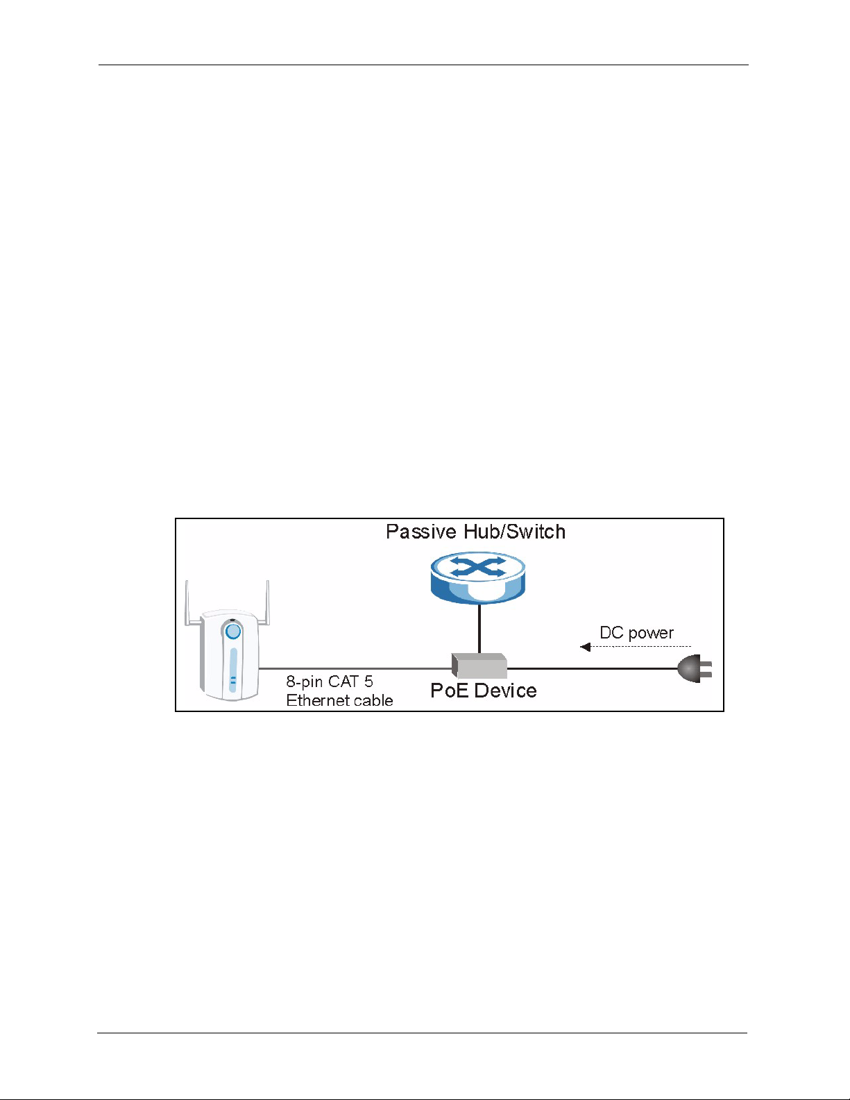
1.2.1.6 Power over Ethernet (PoE)
Power over Ethernet (PoE) is the ability to provide power to your ZyAIR via an 8-pin CAT 5
Ethernet cable, eliminating the need for a nearby power source. An injector or PoE device (not
included) is also needed to supply the Ethernet cable with power. This feature allows increased
flexibility in the locating of your ZyAIR. You only need to connect the external power adaptor
if you are not using PoE. If you simultaneously use both PoE and the external power adaptor,
the ZyAIR will draw power from the PoE connection only. Refer to the appendix for more
information about PoE.
Figure 1 PoE Installation Example
1.2.2 Firmware Features
1.2.2.1 Dual WLAN Interface
The ZyAIR can operate with two WLAN cards. One of the cards is built-in. Another card can
be added using the extension slot on the side panel of the ZyAIR.
With two WLAN cards, the ZyAIR can be set up with two different wireless configurations,
for example, an Access Point with one card and an AP+Bridge with the other card.
29 Chapter 1 Getting to Know Your ZyAIR
Page 31

1.2.2.2 Internal RADIUS Server
The ZyAIR has a built-in RADIUS server that can authenticate wireless clients or other AP’s
in other wireless networks.The ZyAIR can also function as an AP and as a RADIUS server at
the same time.
1.2.2.3 Wi-Fi Protected Access
Wi-Fi Protected Access (WPA) is a subset of the IEEE 802.11i security specification draft.
Key differences between WPA and WEP are user authentication and improved data
encryption.
1.2.2.4 Layer-2 Isolation
Layer-2 isolation is used to prevent wireless clients associated with your ZyAIR from
communicating with other wireless clients, AP’s, computers or routers in a network.
1.2.2.5 VLAN
ZyAIR G-3000 User’s Guide
A VLAN (Virtual Local Area Network) allows a physical network to be partitioned into
multiple logical networks. Only stations within the same group can talk to each other. Stations
on a logical network can belong to one or more groups. The ZyAIR supports 802.1Q VLAN
tagging. Tagged VLAN uses an explicit tag (VLAN ID) in the MAC header of a frame to
identify VLAN membership. The ZyAIR can identify VLAN tags for incoming Ethernet
frames and add VLAN tags to outgoing Ethernet frames.
Configure VLAN (virtual LAN) to extend the wireless logical grouping to the wired network.
A ZyAIR that you configure with the built-in wireless card uses the same Management
VLAN ID as a ZyAIR configured with a removable wireless card.
1.2.2.6 WDS Functionality
A Distribution System (DS) is a wired connection between two or more APs, while a Wireless
Distribution System (WDS) is a wireless connection. Your ZyAIR supports WDS, providing a
cost-effective solution for wireless network expansion.
Chapter 1 Getting to Know Your ZyAIR 30
Page 32
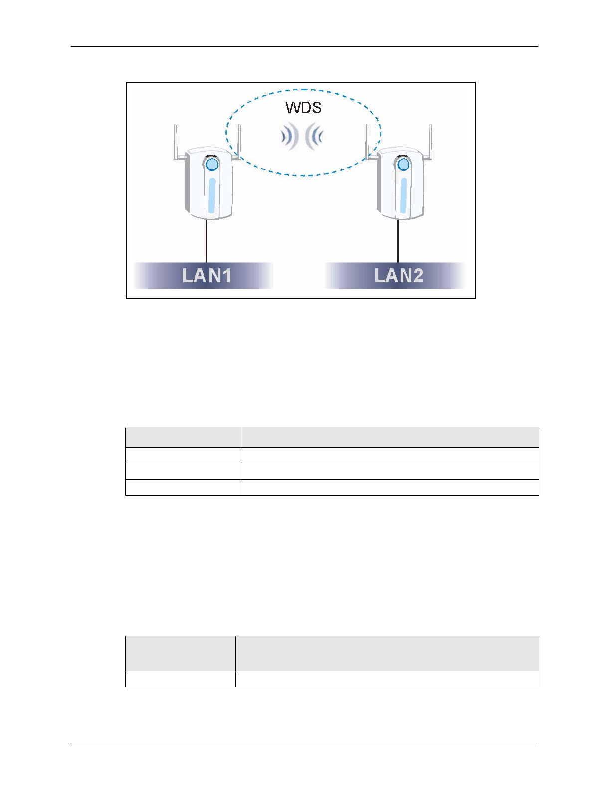
ZyAIR G-3000 User’s Guide
Figure 2 WDS Functionality Example
1.2.2.7 802.11b Wireless LAN Standard
The ZyAIR complies with the 802.11b wireless standard.
The 802.11b data rate and corresponding modulation techniques are shown in the table below.
The modulation technique defines how bits are encoded onto radio waves.
Table 1 IEEE 802.11b
DATA RATE (MBPS) MODULATION
1 DBPSK (Differential Binary Phase Shifted Keying)
2 DQPSK (Differential Quadrature Phase Shifted Keying)
5.5 / 11 CCK (Complementary Code Keying)
1.2.2.8 802.11g Wireless LAN Standard
The ZyAIR, complies with the 802.11g wireless standard and is also fully compatible with the
802.11b standard. This means an 802.11b radio card can interface directly with an 802.11g
device (and vice versa) at 11 Mbps or lower depending on range. 802.11g has several
intermediate rate steps between the maximum and minimum data rates. The 802.11g data rate
and modulation are as follows:
Table 2 IEEE 802.11g
.
DATA RATE
(MBPS)
6/9/12/18/24/36/48/54 OFDM (Orthogonal Frequency Division Multiplexing)
31 Chapter 1 Getting to Know Your ZyAIR
MODULATION
Page 33

Note: The ZyAIR may be prone to RF (Radio Frequency)
interference from other 2.4 GHz devices such as microwave
ovens, wireless phones, Bluetooth enabled devices, and other
wireless LANs.
1.2.2.9 STP (Spanning Tree Protocol) / RSTP (Rapid STP)
(R)STP detects and breaks network loops and provides backup links between switches,
bridges or routers. It allows a bridge to interact with other (R)STP -compliant bridges in your
network to ensure that only one path exists between any two stations on the network.
1.2.2.10 Certificates
The ZyAIR can use certificates (also called digital IDs) to authenticate users. Certificates are
based on public-private key pairs. Certificates provide a way to exchange public keys for use
in authentication.
1.2.2.11 Limit the number of Client Connections
ZyAIR G-3000 User’s Guide
You may set a maximum number of wireless stations that may connect to the ZyAIR. This
may be necessary if for example, there is interference or difficulty with channel assignment
due to a high density of APs within a coverage area.
1.2.2.12 SSL Passthrough
SSL (Secure Sockets Layer) uses a public key to encrypt data that's transmitted over an SSL
connection. Both Netscape Navigator and Internet Explorer support SSL, and many Web sites
use the protocol to obtain confidential user information, such as credit card numbers. By
convention, URLs that require an SSL connection start with “https” instead of “http”. The
ZyAIR allows SSL connections to take place through the ZyAIR.
1.2.2.13 Brute-Force Password Guessing Protection
The ZyAIR has a special protection mechanism to discourage brute-force password guessing
attacks on the ZyAIR's management interfaces. You can specify a wait-time that must expire
before entering a fourth password after three incorrect passwords have been entered. Please
see the appendix for details about this feature.
1.2.2.14 Wireless LAN MAC Address Filtering
Your ZyAIR checks the MAC address of the wireless station against a list of allowed or denied
MAC addresses.
1.2.2.15 WEP Encryption
WEP (Wired Equivalent Privacy) encrypts data frames before transmitting over the wireless
network to help keep network communications private.
Chapter 1 Getting to Know Your ZyAIR 32
Page 34

ZyAIR G-3000 User’s Guide
1.2.2.16 IEEE 802.1x Network Security
The ZyAIR supports the IEEE 802.1x standard to enhance user authentication. Use the built-in
user profile database to authenticate up to 32 users using MD5 encryption. Use an EAPcompatible RADIUS (RFC2138, 2139 - Remote Authentication Dial In User Service) server
to authenticate a limitless number of users using EAP (Extensible Authentication Protocol).
EAP is an authentication protocol that supports multiple types of authentication.
1.2.2.17 SNMP
SNMP (Simple Network Management Protocol) is a protocol used for exchanging
management information between network devices. SNMP is a member of the TCP/IP
protocol suite. Your ZyAIR supports SNMP agent functionality, which allows a manger
station to manage and monitor the ZyAIR through the network. The ZyAIR supports SNMP
version one (SNMPv1) and version two c (SNMPv2c).
1.2.2.18 Full Network Management
The embedded web configurator is an all-platform web-based utility that allows you to easily
access the ZyAIR’s management settings. Most functions of the ZyAIR are also software
configurable via the SMT (System Management Terminal) interface. The SMT is a menudriven interface that you can access from a terminal emulator over a telnet connection.
1.2.2.19 Logging and Tracing
• Built-in message logging and packet tracing.
• Unix syslog facility support.
1.2.2.20 Embedded FTP and TFTP Servers
The ZyAIR’s embedded FTP and TFTP servers enable fast firmware upgrades as well as
configuration file backups and restoration.
1.2.2.21 Wireless Association List
With the wireless association list, you can see the list of the wireless stations that are currently
using the ZyAIR to access your wired network.
1.2.2.22 Wireless LAN Channel Usage
The Wireless Channel Usage screen displays whether the radio channels are used by other
wireless devices within the transmission range of the ZyAIR. This allows you to select the
channel with minimum interference for your ZyAIR.
1.3 Applications for the ZyAIR
Here are some ZyAIR application examples.
33 Chapter 1 Getting to Know Your ZyAIR
Page 35
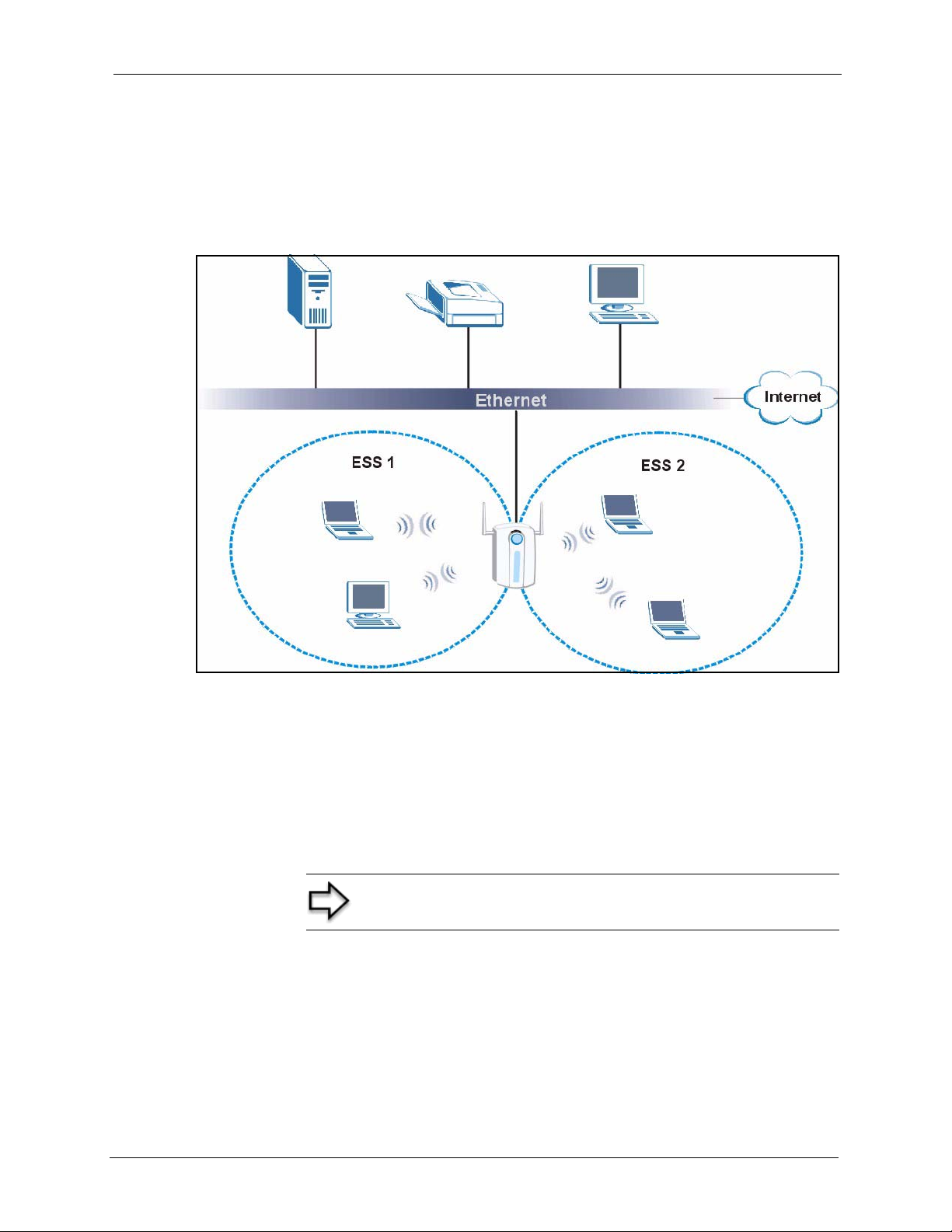
1.3.1 Dual WLAN Interface
The following figure shows an example with the ZyAIR dual WLAN application. One
wireless interface is configured with ESS 1. The other wireless interface is configured with
ESS 2.
Figure 3 Dual WLAN Application
ZyAIR G-3000 User’s Guide
The ZyAIR can be configured using the following WLAN operating modes
1 AP
2 AP+Bridge
3 Bridge/Repeater
Applications for each operating mode are shown below.
1.3.2 Access Point
The ZyAIR is an ideal access solution for wireless Internet connection. A typical Internet
access application for your ZyAIR is shown as follows. Stations A, B and C can access the
wired network through the ZyAIRs.
Note: A different channel should be configured for each WLAN
interface to reduce the effects of radio interference.
Chapter 1 Getting to Know Your ZyAIR 34
Page 36

ZyAIR G-3000 User’s Guide
Figure 4 Access Point Application
1.3.3 AP + Bridge
In AP+Bridge mode, the ZyAIR supports both AP (A and B can connect to the wired network
through X) and bridge (X can communicate with Y) connection at the same time.
When the ZyAIR is in AP + Bridge mode, the traffic between ZyAIRs (the WDS) is not
encrypted. The security settings on the ZyAIR refer to the traffic between the wireless station
and the ZyAIR.
35 Chapter 1 Getting to Know Your ZyAIR
Page 37
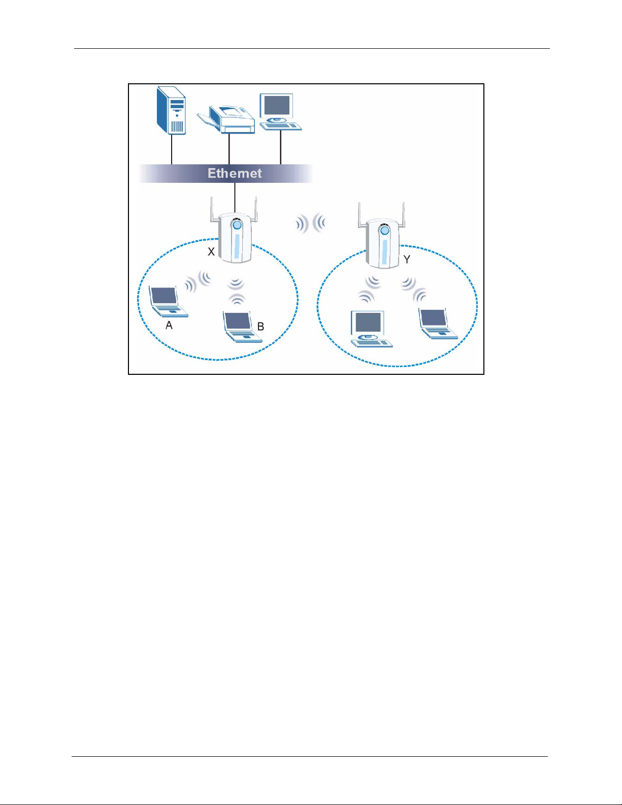
Figure 5 AP+Bridge Application
ZyAIR G-3000 User’s Guide
1.3.4 Bridge / Repeater
The ZyAIR can act as a wireless network bridge and establish wireless links with other APs. In
bridge mode, the ZyAIR’s (A and B) are connected to independent wired networks and have a
bridge (A can communicate with B) connection at the same time. A ZyAIR in repeater mode
(C) has no Ethernet connection. When the ZyAIR is in the bridge mode, you should enable
STP to prevent bridge loops.
When the ZyAIR is in Bridge/Repeater mode, you don’t have to enter a pre-shared key, but
the traffic between devices won’t be encrypted if you don’t. The peer bridge must use the same
pre-shared key and encryption method.
The ZyAIR in AP+Bridge mode cannot connect to another ZyAIR in Bridge/Repeater mode
that uses manual WEP keys with 64-bit or 128-bit WEP encryption.
Chapter 1 Getting to Know Your ZyAIR 36
Page 38

ZyAIR G-3000 User’s Guide
Figure 6 Bridge Application
Figure 7 Repeater Application
37 Chapter 1 Getting to Know Your ZyAIR
Page 39
CHAPTER 2
Introducing the Web
Configurator
This chapter describes how to access the ZyAIR web configurator and provides an overview
of its screens. The default IP address of the ZyAIR is 192.168.1.2.
2.1 Accessing the ZyAIR Web Configurator
1 Make sure your ZyAIR hardware is properly connected and prepare your computer/
computer network to connect to the ZyAIR (refer to the Quick Start Guide).
2 Launch your web browser.
ZyAIR G-3000 User’s Guide
3 Typ e "192.168.1.2" as the URL.
4 Typ e "1234" (default) as the password and click Login. In some versions, the default
password appears automatically - if this is the case, click Login.
5 You should see a screen asking you to change your password (highly recommended) as
shown next. Type a new password (and retype it to confirm) and click Apply or click
Ignore.
Note: If you do not change the password, the following screen
appears every time you login.
Chapter 2 Introducing the Web Configurator 38
Page 40
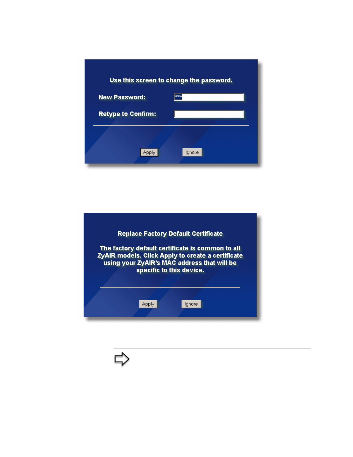
ZyAIR G-3000 User’s Guide
Figure 8 Change Password Screen
6 Click Apply in the Replace Certificate screen to create a certificate using your ZyAIR’s
MAC address that will be specific to this device.
Figure 9 Replace Certificate Screen
You should now see the MAIN MENU screen..
Note: The management session automatically times out when
the time period set in the Administrator Inactivity Timer field
expires (default five minutes). Simply log back into the ZyAIR if
this happens to you.
39 Chapter 2 Introducing the Web Configurator
Page 41

2.2 Resetting the ZyAIR
If you forget your password or cannot access the web configurator, you will need to reload the
factory-default configuration file or use the RESET button on the side panel of the ZyAIR.
Uploading this configuration file replaces the current configuration file with the factorydefault configuration file. This means that you will lose all configurations that you had
previously. The password will be reset to 1234.
2.2.1 .Procedure To Use The Reset Button
Make sure the SYS LED is on (not blinking) before you begin this procedure.
1 Press the RESET button for ten seconds or until the SYS LED, LINK LED or BDG/
RPT LED turns red, and then release it. If the SYS LED begins to blink, the defaults have
been restored and the ZyAIR restarts. Otherwise, go to step 2.
2 Turn the ZyAIR off.
3 While pressing the RESET button, turn the ZyAIR on.
4 Continue to hold the RESET button. The SYS LED will begin to blink and flicker very
quickly after about 20 seconds. This indicates that the defaults have been restored and the
ZyAIR is now restarting.
ZyAIR G-3000 User’s Guide
5 Release the RESET button and wait for the ZyAIR to finish restarting.
2.2.2 Method of Restoring Factory-Defaults
You can erase the current configuration and restore factory defaults in three ways:
Use the RESET button on the side panel of the ZyAIR to upload the default configuration file
(hold this button in for about 10 seconds or until the SYS LED, LINK LED or BDG/RPT
LED turns red). Use this method for cases when the password or IP address of the ZyAIR is
not known.
Use the web configurator to restore defaults (refer to Chapter 13, on page 146 ).
Transfer the configuration file to your ZyAIR using FTP. See later in the part on SMT
configuration for more information.
2.3 Navigating the ZyAIR Web Configurator
We use the ZyAIR G-3000 web configurator in this guide as an example. The web
configurator screens for your model may vary slightly for different ZyAIR models.
Chapter 2 Introducing the Web Configurator 40
Page 42

ZyAIR G-3000 User’s Guide
The following summarizes how to navigate the web configurator from the MAIN MENU
screen.
The icon does not appear in the MAIN MENU screen.
Figure 10 The MAIN MENU Screen of the Web Configurator
Note: Follow the instructions you see in the MAIN MENU
screen or click the
icon (located in the top right corner of
most screens) to view online help.
Click WIZARD SETUP for initial configuration including general setup, Wireless LAN
setup and IP address assignment.
Click the links under ADVANCED to configure advanced features such as SYSTEM
(General Setup, Password and Time Zone), WIRELESS (Wireless, Layer-2 Isolation, MAC
Filter, Roaming and 802.1x/WPA), IP, REMOTE MGNT (Telnet, FTP, WWW and SNMP),
Internal RADIUS Server
(
My Certificates, Trusted CAs), LOGS (View reports and Log Settings) and VLAN.
(Settings, Trusted AP and Trusted User databases), CERTIFICATES
Click MAINTENANCE to view information about your ZyAIR or upgrade configuration/
firmware files. Maintenance includes Status (Statistics), Association List, Channel Usage,
F/W (firmware) Upload, Configuration (Backup, Restore and Default) and Restart
Click LOGOUT at any time to exit the web configurator
41 Chapter 2 Introducing the Web Configurator
Page 43

This chapter provides information on the Wizard Setup screens in the web configurator.
3.1 Wizard Setup Overview
The web configurator’s setup wizard helps you configure your ZyAIR for wireless stations to
access your wired LAN. The wizard applies configuration settings to the ZyAIR built-in
wireless card by default, even if you have installed another card.
3.1.1 Channel
A channel is the radio frequency(ies) used by IEEE 802.11b and IEEE 802.11g wireless
devices. Channels available depend on your geographical area. You may have a choice of
channels (for your region) so you should use a different channel than an adjacent AP (access
point) to reduce interference. Interference occurs when radio signals from different access
points overlap causing interference and degrading performance.
ZyAIR G-3000 User’s Guide
CHAPTER 3
Wizard Setup
Adjacent channels partially overlap however. To avoid interference due to overlap, your AP
should be on a channel at least five channels away from a channel that an adjacent AP is using.
For example, if your region has 11 channels and an adjacent AP is using channel 1, then you
need to select a channel between 6 or 11.
The ZyAIR’s “Scan” function is especially designed to automatically scan for a channel with
the least interference.
3.1.2 ESS ID
An Extended Service Set (ESS) is a group of access points connected to a wired LAN on the
same subnet. An SS ID uniquely identifies each set. All access points and their associated
wireless stations in the same set must have the same SSID.
3.1.3 WEP Encryption
WEP (Wired Equivalent Privacy) encrypts data frames before transmitting over the wireless
network. WEP encryption scrambles the data transmitted between the wireless stations and the
access points to keep network communications private. It encrypts unicast and multicast
communications in a network. Both the wireless stations and the access points must use the
same WEP key for data encryption and decryption.
Chapter 3 Wizard Setup 42
Page 44

ZyAIR G-3000 User’s Guide
3.2 Wizard Setup: General Setup
General Setup contains administrative and system-related information.
The Domain Name entry is what is propagated to the DHCP clients on the LAN. If you leave
this blank, the domain name obtained by DHCP from the ISP is used. While you must enter
the host name (System Name) on each individual computer, the domain name can be assigned
from the ZyAIR via DHCP.
Figure 11 Wizard 1 : General Setup
The following table describes the labels in this screen.
Table 3 Wizard 1 : General Setup
LABEL DESCRIPTION
System Name It is recommended you type your computer's "Computer name".
In Windows 95/98 click Start, Settings, Control Panel, Network. Click the
Identification tab, note the entry for the Computer Name field and enter it as the
System Name.
In Windows 2000, click Start, Settings, Control Panel and then double-click
System. Click the Network Identification tab and then the Properties button.
Note the entry for the Computer name field and enter it as the System Name.
In Windows XP, click Start, My Computer, View system information and then
click the Computer Name tab. Note the entry in the Full computer name field
and enter it as the ZyAIR System Name.
This name can be up to 30 alphanumeric characters long. Spaces are not
allowed, but dashes "-" and underscores "_" are accepted.
Domain Name This is not a required field. Leave this field blank or enter the domain name here
if you know it.
Next Click Next to proceed to the next screen.
43 Chapter 3 Wizard Setup
Page 45

3.3 Wizard Setup: Wireless LAN
Use the second wizard screen to set up the wireless LAN.
Figure 12 Wizard 2 : Wireless LAN Setup
ZyAIR G-3000 User’s Guide
The following table describes the labels in this screen.
Table 4 Wizard 2 : Wireless LAN Setup
LABEL DESCRIPTION
Wireless LAN Setup
WLAN Adaptor Select Built-in from the drop down list box to configure your ZyAIR using the
internal WLAN card. Select Removable from the drop down list box to
configure your ZyAIR using a WLAN card adaptor using the extension card
slot.
Note: This field is only available when you have an external
wireless card inserted in the ZyAIR.
Name (SSID) Enter a descriptive name (up to 32 printable 7-bit ASCII characters) for the
Choose Channel ID To manually set the ZyAIR to use a channel, select a channel from the drop-
Scan Click this button to have the ZyAIR automatically scan for and select a channel
WEP Encryption Select Disable allows all wireless computers to communicate with the access
ASCII Select this option in order to enter ASCII characters as the WEP keys.
wireless LAN.
If you change this field on the ZyAIR, make sure all wireless stations use the
same Name (SSID) in order to access the network.
down list box. Open the Channel Usage screen to make sure the channel is
not already used by another AP or independent peer-to-peer wireless network.
To have the ZyAIR automatically select a channel, click Scan instead.
with the least interference.
points without any data encryption.
Select 64-bit WEP or 128-bit WEP to allow data encryption.
Chapter 3 Wizard Setup 44
Page 46

ZyAIR G-3000 User’s Guide
Table 4 Wizard 2 : Wireless LAN Setup
LABEL DESCRIPTION
Hex Select this option to enter hexadecimal characters as the WEP keys.
The preceding 0x is entered automatically.
Key 1 to Key 4 The WEP keys are used to encrypt data. Both the ZyAIR and the wireless
stations must use the same WEP key for data transmission.
If you chose 64-bit WEP, then enter any 5 ASCII characters or 10 hexadecimal
characters ("0-9", "A-F").
If you chose 128-bit WEP, then enter 13 ASCII characters or 26 hexadecimal
characters ("0-9", "A-F").
You must configure all four keys, but only one key can be activated at any one
time. The default key is key 1.
Back Click Back to return to the previous screen.
Next Click Next to continue.
3.4 Wizard Setup: IP Address
The third wizard screen allows you to configure IP address assignment.
3.4.1 IP Address Assignment
Every computer on the Internet must have a unique IP address. If your networks are isolated
from the Internet, for instance, only between your two branch offices, you can assign any IP
addresses to the hosts without problems. However, the Internet Assigned Numbers Authority
(IANA) has reserved the following three blocks of IP addresses specifically for private
networks.
Table 5 Private IP Address Ranges
10.0.0.0 - 10.255.255.255
172.16.0.0 - 172.31.255.255
192.168.0.0 - 192.168.255.255
You can obtain your IP address from the IANA, from an ISP or have it assigned by a private
network. If you belong to a small organization and your Internet access is through an ISP, the
ISP can provide you with the Internet addresses for your local networks. On the other hand, if
you are part of a much larger organization, you should consult your network administrator for
the appropriate IP addresses.
Note: Regardless of your particular situation, do not create an
arbitrary IP address; always follow the guidelines above. For
more information on address assignment, please refer to RFC
1597, Address Allocation for Private Internets and RFC 1466,
Guidelines for Management of IP Address Space.
45 Chapter 3 Wizard Setup
Page 47

3.4.2 IP Address and Subnet Mask
Similar to the way houses on a street share a common street name, so too do computers on a
LAN share one common network number.
Where you obtain your network number depends on your particular situation. If the ISP or
your network administrator assigns you a block of registered IP addresses, follow their
instructions in selecting the IP addresses and the subnet mask.
If the ISP did not explicitly give you an IP network number, then most likely you have a single
user account and the ISP will assign you a dynamic IP address when the connection is
established. The Internet Assigned Number Authority (IANA) reserved this block of addresses
specifically for private use; please do not use any other number unless you are told otherwise.
Let's say you select 192.168.1.0 as the network number; which covers 254 individual
addresses, from 192.168.1.1 to 192.168.1.254 (zero and 255 are reserved). In other words, the
first three numbers specify the network number while the last number identifies an individual
computer on that network.
Once you have decided on the network number, pick an IP address that is easy to remember,
for instance, 192.168.1.2, for your ZyAIR, but make sure that no other device on your network
is using that IP address.
ZyAIR G-3000 User’s Guide
The subnet mask specifies the network number portion of an IP address. Your ZyAIR will
compute the subnet mask automatically based on the IP address that you entered. You don't
need to change the subnet mask computed by the ZyAIR unless you are instructed to do
otherwise.
Chapter 3 Wizard Setup 46
Page 48
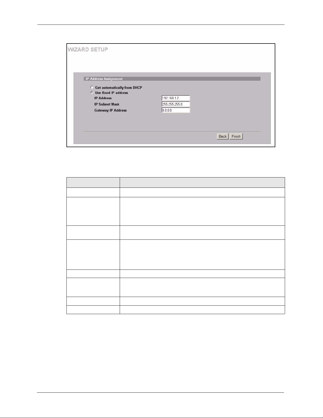
ZyAIR G-3000 User’s Guide
Figure 13 Wizard 3 : IP Address Assignment
The following table describes the labels in this screen.
Table 6 Wizard 3 : IP Address Assignment
LABEL DESCRIPTION
IP Address Assignment
Get automatically from
DHCP
Select this option if your ZyAIR is using a dynamically assigned IP address
from a DHCP server each time.
Note: You must know the IP address assigned to the ZyAIR (by
the DHCP server) to access the ZyAIR again.
Use fixed IP address Select this option if your ZyAIR is using a static IP address. When you select
IP Address Enter the IP address of your ZyAIR in dotted decimal notation.
this option, fill in the fields below.
Note: If you changed the ZyAIR's IP address, you must use the
new IP address if you want to access the web configurator
again.
IP Subnet Mask Type the subnet mask.
Gateway IP Address Type the IP address of the gateway. The gateway is an immediate neighbour
Back Click Back to return to the previous screen.
Finish Click Finish to proceed to complete the Wizard setup.
of your ZyAIR that will forward the packet to the destination. The gateway
must be a router on the same segment as your ZyAIR's LAN or WAN port.
47 Chapter 3 Wizard Setup
Page 49

3.5 Basic Setup Complete
When you click Finish in the Wizard 3 IP Address Assignment screen, a warning window
display as shown. Click OK to close the window and log in to the web configurator again
using the new IP address if you change the default IP address (192.168.1.2).
You have successfully set up the ZyAIR. A screen displays prompting you to close the web
browser.
ZyAIR G-3000 User’s Guide
Click Ye s. Otherwise, click No and the congratulations screen shows next.
Figure 14 Wizard 4 : Setup Complete
Well done! You have successfully set up your ZyAIR to operate on your network and access
the Internet.
Chapter 3 Wizard Setup 48
Page 50

ZyAIR G-3000 User’s Guide
49 Chapter 3 Wizard Setup
Page 51

4.1 System Overview
This section provides information on general system setup.
4.2 Configuring General Setup
Click the SYSTEM link under ADVANCED to open the General screen.
Figure 15 System General Setup
ZyAIR G-3000 User’s Guide
CHAPTER 4
System Screens
The following table describes the labels in this screen.
Table 7 System General Setup
LABEL DESCRIPTION
General Setup
System Name Type a descriptive name to identify the ZyAIR in the Ethernet network.
This name can be up to 30 alphanumeric characters long. Spaces are not
allowed, but dashes "-" and underscores "_" are accepted.
Domain Name This is not a required field. Leave this field blank or enter the domain name
Chapter 4 System Screens 50
here if you know it.
Page 52

ZyAIR G-3000 User’s Guide
Table 7 System General Setup
LABEL DESCRIPTION
Administrator
Inactivity Timer
System DNS Servers
First DNS Server
Second DNS Server
Third DNS Server
Apply Click Apply to save your changes back to the ZyAIR.
Reset Click Reset to reload the previous configuration for this screen.
Type how many minutes a management session (either via the web
configurator or SMT) can be left idle before the session times out.
The default is 5 minutes. After it times out you have to log in with your
password again. Very long idle timeouts may have security risks.
A value of "0" means a management session never times out, no matter how
long it has been left idle (not recommended).
Select From DHCP if your DHCP server dynamically assigns DNS server
information (and the ZyAIR's Ethernet IP address). The field to the right
displays the (read-only) DNS server IP address that the DHCP assigns.
Select User-Defined if you have the IP address of a DNS server. Enter the
DNS server's IP address in the field to the right. If you chose User-Defined, but
leave the IP address set to 0.0.0.0, User-Defined changes to None after you
click Apply. If you set a second choice to User-Defined, and enter the same IP
address, the second User-Defined changes to None after you click Apply.
Select None if you do not want to configure DNS servers. If you do not
configure a DNS server, you must know the IP address of a machine in order to
access it.
The default setting is None.
4.3 Configuring Password
To change your ZyAIR’s password (recommended), click the SYSTEM link under
ADVANCED and then the Password tab. The screen appears as shown. This screen allows
you to change the ZyAIR’s password.
If you forget your password (or the ZyAIR IP address), you will need to reset the ZyAIR. See
the Resetting the ZyAIR section for details
51 Chapter 4 System Screens
Page 53

ZyAIR G-3000 User’s Guide
Figure 16 Password.
The following table describes the labels in this screen.
Table 8 Password
LABEL DESCRIPTIONS
Old Password Type in your existing system password (1234 is the default password).
New Password Type your new system password (up to 31 characters). Note that as you type a
password, the screen displays an asterisk (*) for each character you type.
Retype to Confirm Retype your new system password for confirmation.
Apply Click Apply to save your changes back to the ZyAIR.
Reset Click Reset to reload the previous configuration for this screen.
4.4 Configuring Time Setting
To change your ZyAIR’s time and date, click the SYSTEM link under ADVANCED and then
the Time Setting tab. The screen appears as shown. Use this screen to configure the ZyAIR’s
time based on your local time zone.
Chapter 4 System Screens 52
Page 54

ZyAIR G-3000 User’s Guide
Figure 17 Time Setting
The following table describes the labels in this screen.
Table 9 Time Setting
LABEL DESCRIPTION
Time Protocol Select the time service protocol that your time server sends when you turn on
Time Server Address Enter the IP address or the URL of your time server. Check with your ISP/
Current Time
(hh:mm:ss)
New Time (hh:mm:ss) This field displays the last updated time from the time server.
Current Date (yyyy/
mm/dd)
the ZyAIR. Not all time servers support all protocols, so you may have to check
with your ISP/network administrator or use trial and error to find a protocol that
works.
The main difference between them is the format.
Daytime (RFC 867) format is day/month/year/time zone of the server.
Time (RFC 868) format displays a 4-byte integer giving the total number of
seconds since 1970/1/1 at 0:0:0.
The default, NTP (RFC 1305), is similar to Time (RFC 868).
Select None to enter the time and date manually.
network administrator if you are unsure of this information.
This field displays the time of your ZyAIR.
Each time you reload this page, the ZyAIR synchronizes the time with the time
server.
When you select None in the Time Protocol field, enter the new time in this
field and then click Apply.
This field displays the date of your ZyAIR.
Each time you reload this page, the ZyAIR synchronizes the date with the time
server.
53 Chapter 4 System Screens
Page 55

Table 9 Time Setting
LABEL DESCRIPTION
ZyAIR G-3000 User’s Guide
New Date (yyyy/mm/
dd)
Time Zone Choose the time zone of your location. This will set the time difference
Daylight Savings Select this option if you use daylight savings time. Daylight saving is a period
Start Date (mm-dd) Enter the month and day that your daylight-savings time starts on if you
End Date (mm-dd) Enter the month and day that your daylight-savings time ends on if you
Apply Click Apply to save your changes back to the ZyAIR.
Reset Click Reset to reload the previous configuration for this screen.
This field displays the last updated date from the time server.
When you select None in the Time Protocol field, enter the new date in this
field and then click Apply.
between your time zone and Greenwich Mean Time (GMT).
from late spring to early fall when many countries set their clocks ahead of
normal local time by one hour to give more daytime light in the evening.
selected Daylight Savings.
selected Daylight Savings.
Chapter 4 System Screens 54
Page 56

ZyAIR G-3000 User’s Guide
55 Chapter 4 System Screens
Page 57

Wireless Configuration and
This chapter discusses how to configure Wireless and Roaming screens on the ZyAIR.
5.1 Wireless LAN Overview
This section introduces the wireless LAN (WLAN) and some basic scenarios.
5.1.1 IBSS
ZyAIR G-3000 User’s Guide
CHAPTER 5
Roaming
An Independent Basic Service Set (IBSS), also called an Ad-hoc network, is the simplest
WLAN configuration. An IBSS is defined as two or more computers with wireless adapters
within range of each other that from an independent (wireless) network without the need of an
access point (AP).
Figure 18 IBSS (Ad-hoc) Wireless LAN
5.1.2 BSS
A Basic Service Set (BSS) exists when all communications between wireless stations or
between a wireless station and a wired network client go through one access point (AP).
Chapter 5 Wireless Configuration and Roaming 56
Page 58

ZyAIR G-3000 User’s Guide
Intra-BSS traffic is traffic between wireless stations in the BSS. When Intra-BSS is enabled,
wireless station A and B can access the wired network and communicate with each other.
When Intra-BSS is disabled, wireless station A and B can still access the wired network but
cannot communicate with each other.
Figure 19 Basic Service set
5.1.3 ESS
An Extended Service Set (ESS) consists of a series of overlapping BSSs, each containing an
access point, with each access point connected together by a wired network. This wired
connection between APs is called a Distribution System (DS). An ESSID (ESS IDentification)
uniquely identifies each ESS. All access points and their associated wireless stations within
the same ESS must have the same ESSID in order to communicate.
57 Chapter 5 Wireless Configuration and Roaming
Page 59
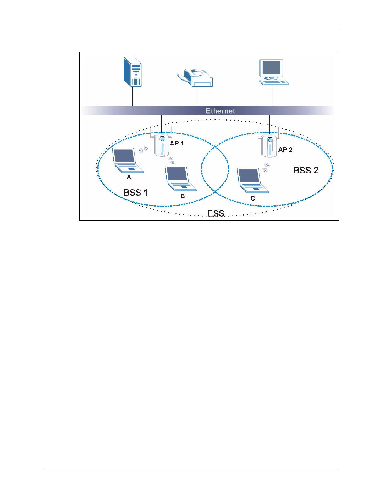
Figure 20 Extended Service Set
ZyAIR G-3000 User’s Guide
5.2 Wireless LAN Basics
Refer also to the Wizard Setup chapter for more background information on Wireless LAN
features, such as channels.
5.2.1 RTS/CTS
A hidden node occurs when two stations are within range of the same access point, but are not
within range of each other. The following figure illustrates a hidden node. Both stations (STA)
are within range of the access point (AP) or wireless gateway, but out-of-range of each other,
so they cannot “hear” each other, that is they do not know if the channel is currently being
used. Therefore, they are considered hidden from each other.
Chapter 5 Wireless Configuration and Roaming 58
Page 60

ZyAIR G-3000 User’s Guide
Figure 21 RTS/CTS
When station A sends data to the ZyAIR, it might not know that the station B is already using
the channel. If these two stations send data at the same time, collisions may occur when both
sets of data arrive at the AP at the same time, resulting in a loss of messages for both stations.
RTS/CTS is designed to prevent collisions due to hidden nodes. An RTS/CTS defines the
biggest size data frame you can send before an RTS (Request To Send)/CTS (Clear to Send)
handshake is invoked.
When a data frame exceeds the RTS/CTS value you set (between 0 to 2432 bytes), the station
that wants to transmit this frame must first send an RTS (Request To Send) message to the AP
for permission to send it. The AP then responds with a CTS (Clear to Send) message to all
other stations within its range to notify them to defer their transmission. It also reserves and
confirms with the requesting station the time frame for the requested transmission.
Stations can send frames smaller than the specified RTS/CTS directly to the AP without the
RTS (Request To Send)/CTS (Clear to Send) handshake.
You should only configure RTS/CTS if the possibility of hidden nodes exists on your network
and the “cost” of resending large frames is more than the extra network overhead involved in
the RTS (Request To Send)/CTS (Clear to Send) handshake.
If the RTS/CTS value is greater than the Fragmentation Threshold value (see next), then the
RTS (Request To Send)/CTS (Clear to Send) handshake will never occur as data frames will
be fragmented before they reach RTS/CTS size.
Note: Enabling the RTS Threshold causes redundant network
overhead that could negatively affect the throughput
performance instead of providing a remedy.
5.2.2 Fragmentation Threshold
A Fragmentation Threshold is the maximum data fragment size (between 256 and 2432
bytes) that can be sent in the wireless network before the ZyAIR will fragment the packet into
smaller data frames.
59 Chapter 5 Wireless Configuration and Roaming
Page 61

A large Fragmentation Threshold is recommended for networks not prone to interference
while you should set a smaller threshold for busy networks or networks that are prone to
interference.
If the Fragmentation Threshold value is smaller than the RTS/CTS value (see previously)
you set then the RTS (Request To Send)/CTS (Clear to Send) handshake will never occur as
data frames will be fragmented before they reach RTS/CTS size.
5.3 Spanning Tree Protocol (STP)
STP detects and breaks network loops and provides backup links between switches, bridges or
routers. It allows a bridge to interact with other STP-compliant bridges in your network to
ensure that only one route exists between any two stations on the network.
5.3.1 Rapid STP
The ZyAIR uses IEEE 802.1w RSTP (Rapid Spanning Tree Protocol) that allow faster
convergence of the spanning tree (while also being backwards compatible with STP-only
aware bridges). Using RSTP topology change information does not have to propagate to the
root bridge and unwanted learned addresses are flushed from the filtering database. In RSTP,
the port states are Discarding, Learning, and Forwarding.
ZyAIR G-3000 User’s Guide
5.3.2 STP Terminology
The root bridge is the base of the spanning tree; it is the bridge with the lowest identifier value
(MAC address).
Path cost is the cost of transmitting a frame onto a LAN through that port. It is assigned
according to the speed of the link to which a port is attached. The slower the media, the higher
the cost - see the next table.
Table 10 STP Path Costs
LINK SPEED
Path Cost 4Mbps 250 100 to 1000 1 to 65535
Path Cost 10Mbps 100 50 to 600 1 to 65535
Path Cost 16Mbps 62 40 to 400 1 to 65535
Path Cost 100Mbps 19 10 to 60 1 to 65535
Path Cost 1Gbps 4 3 to 10 1 to 65535
Path Cost 10Gbps 2 1 to 5 1 to 65535
On each bridge, the root port is the port through which this bridge communicates with the root.
It is the port on this switch with the lowest path cost to the root (the root path cost). If there is
no root port, then this bridge has been accepted as the root bridge of the spanning tree network.
RECOMMENDED
VALUE
RECOMMENDED
RANGE
ALLOWED
RANGE
Chapter 5 Wireless Configuration and Roaming 60
Page 62

ZyAIR G-3000 User’s Guide
For each LAN segment, a designated bridge is selected. This bridge has the lowest cost to the
root among the bridges connected to the LAN.
5.3.3 How STP Works
After a bridge determines the lowest cost-spanning tree with STP, it enables the root port and
the ports that are the designated ports for connected LANs, and disables all other ports that
participate in STP. Network packets are therefore only forwarded between enabled ports,
eliminating any possible network loops.
STP-aware bridges exchange Bridge Protocol Data Units (BPDUs) periodically. When the
bridged LAN topology changes, a new spanning tree is constructed.
Once a stable network topology has been established, all bridges listen for Hello BPDUs
(Bridge Protocol Data Units) transmitted from the root bridge. If a bridge does not get a Hello
BPDU after a predefined interval (Max Age), the bridge assumes that the link to the root
bridge is down. This bridge then initiates negotiations with other bridges to reconfigure the
network to re-establish a valid network topology.
5.3.4 STP Port States
STP assigns five port states (see next table) to eliminate packet looping. A bridge port is not
allowed to go directly from blocking state to forwarding state so as to eliminate transient
loops.
Table 11 STP Port States
PORT STATES DESCRIPTIONS
Disabled STP is disabled (default).
Blocking Only configuration and management BPDUs are received and processed.
Listening All BPDUs are received and processed.
Learning All BPDUs are received and processed. Information frames are submitted to the
Forwarding All BPDUs are received and processed. All information frames are received and
5.4 Preamble
A preamble is used to synchronize the transmission timing in your wireless network. There are
two preamble modes: Long and Short.
learning process but not forwarded.
forwarded.
Short preamble takes less time to process and minimizes overhead, so it should be used in a
good wireless network environment when all wireless clients support it.
61 Chapter 5 Wireless Configuration and Roaming
Page 63

Select Long if you have a ‘noisy’ network or are unsure of what preamble mode your wireless
clients support as all IEEE 802.11b compliant wireless adapters must support long preamble.
However, not all wireless adapters support short preamble. Use long preamble if you are
unsure what preamble mode the wireless adapters support, to ensure interpretability between
the ZyAIR and the wireless stations and to provide more reliable communication in ‘noisy’
networks.
Select Dynamic to have the ZyAIR automatically use short preamble when all wireless clients
support it, otherwise the ZyAIR uses long preamble.
Note: The ZyAIR and the wireless stations MUST use the same
preamble mode in order to communicate.
5.5 Configuring Wireless
Click the WIRELESS link under ADVANCED to display the Wireless screen. The screen
varies depending upon the operating mode you select.
ZyAIR G-3000 User’s Guide
The WLAN Adapter drop down list box is only available when you have an external wireless
card inserted in the ZyAIR. No matter whether you select Built-in or Removable, the
configuration screens are the same for each interface. The following configuration screens
show the Built-in WLAN adapter selected.
The ADVANCED Wireless and ADVANCED MAC Filter screens are configured
independently for each card. All other screens are common to both WLAN cards.
5.5.1 Access Point Mode
Select Access Point Operating Mode to display the screen as shown next.
Chapter 5 Wireless Configuration and Roaming 62
Page 64
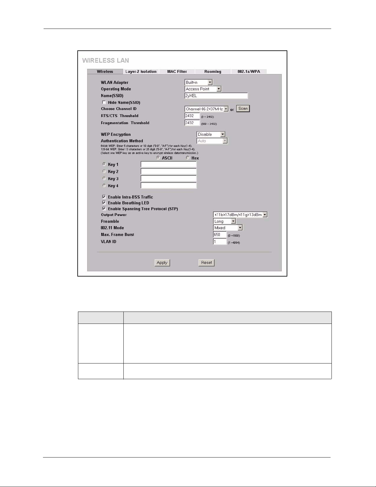
ZyAIR G-3000 User’s Guide
Figure 22 Wireless : Access Point
The following table describes the general wireless LAN labels in this screen.
Table 12 Wireless : Access Point
LABEL DESCRIPTION
WLAN Adapter Select Built-in from the drop down list box to configure your ZyAIR using the
internal WLAN card. Select Removable from the drop down list box to configure
your ZyAIR using a WLAN card adapter using the extension card slot.
Note: This field is only available when you have an external wireless
card inserted in the ZyAIR.
Operating Mode Select the operating mode from the drop-down list. The options are Access Point,
Bridge/Repeater and AP+Bridge.
63 Chapter 5 Wireless Configuration and Roaming
Page 65

ZyAIR G-3000 User’s Guide
Table 12 Wireless : Access Point
LABEL DESCRIPTION
Name (SSID) The SSID (Service Set IDentity) identifies the Service Set with which a wireless
station is associated. Wireless stations associating to the access point (AP) must
have the same SSID. Enter a descriptive name (up to 32 printable 7-bit ASCII
characters) for the wireless LAN.
Note: If you are configuring the ZyAIR from a computer connected to
the wireless LAN and you change the ZyAIR’s SSID or WEP
settings, you will lose your wireless connection when you press
Apply to confirm. You must then change the wireless settings of your
computer to match the ZyAIR’s new settings.
Hide Name
(SSID)
Choose Channel IDSet the operating frequency/channel depending on your particular region.
Scan Click this button to have the ZyAIR automatically scan for and select a channel with
RTS/CTS
Threshold
Fragmentation
Threshold
WEP Encryption WEP (Wired Equivalent Privacy) provides data encryption to prevent unauthorized
Authentication
Method
Key 1 to Key 4 If you chose 64-bit WEP in the WEP Encryption field, then enter any 5 characters
Enable IntraBSS Traffic
Select this check box to hide the SSID in the outgoing beacon frame so a station
cannot obtain the SSID through passive scanning using a site survey tool.
To manually set the ZyAIR to use a channel, select a channel from the drop-down
list box. Click MAINTENANCE and then the Channel Usage tab to open the
Channel Usage screen to make sure the channel is not already used by another AP
or independent peer-to-peer wireless network.
To have the ZyAIR automatically select a channel, click Scan instead.
Refer to the Wizard Setup chapter for more information on channels.
the least interference.
(Request To Send) The threshold (number of bytes) for enabling RTS/CTS
handshake. Data with its frame size larger than this value will perform the RTS/CTS
handshake. Setting this attribute to be larger than the maximum MSDU (MAC
service data unit) size turns off the RTS/CTS handshake. Setting this attribute to
zero turns on the RTS/CTS handshake. Enter a value between 0 and 2432.
The threshold (number of bytes) for the fragmentation boundary for directed
messages. It is the maximum data fragment size that can be sent. Enter a value
between 800 and 2432.
wireless stations from accessing data transmitted over the wireless network.
Select Disable to allow wireless stations to communicate with the access points
without any data encryption.
Select 64-bit WEP or 128-bit WEP to enable data encryption.
Select Auto, Open System or Shared Key from the drop-down list box.
(ASCII string) or 10 hexadecimal characters ("0-9", "A-F") preceded by 0x for each
key.
If you chose 128-bit WEP in the WEP Encryption field, then enter 13 characters
(ASCII string) or 26 hexadecimal characters ("0-9", "A-F") preceded by 0x for each
key.
There are four data encryption keys to secure your data from eavesdropping by
unauthorized wireless users. The values for the keys must be set up exactly the
same on the access points as they are on the wireless stations.
The preceding “0x” is entered automatically. You must configure all four keys, but
only one key can be activated at any one time. The default key is key 1.
Intra-BSS traffic is traffic between wireless stations in the same BSS. Select this
check box to enable Intra-BSS traffic.
Chapter 5 Wireless Configuration and Roaming 64
Page 66

ZyAIR G-3000 User’s Guide
Table 12 Wireless : Access Point
LABEL DESCRIPTION
Enable
Breathing LED
Enable
Spanning Tree
Control (STP)
Output Power Set the output power of the ZyAIR in this field. If there is a high density of APs within
Preamble Select a preamble type from the drop-down list menu. Choices are Long, Short and
802.11 Mode Select 802.11b Only to allow only IEEE 802.11b compliant WLAN devices to
Max. Frame
Burst
VLAN ID Enter a number from 1 to 4094 to define this VLAN group. At least one device in
Apply Click Apply to save your changes back to the ZyAIR.
Reset Click Reset to begin configuring this screen afresh.
Select this check box to enable the Breathing LED, also known as the ZyAIR LED.
The blue ZyAIR LED is on when the ZyAIR is on and blinks (or breaths) when data is
being transmitted to/from its wireless stations.
Clear the check box to turn this LED off even when the ZyAIR is on and data is being
transmitted/received.
(R)STP detects and breaks network loops and provides backup links between
switches, bridges or routers. It allows a bridge to interact with other (R)STP compliant bridges in your network to ensure that only one path exists between any
two stations on the network. Select the check box to activate STP on the ZyAIR.
an area, decrease the output power of the ZyAIR to reduce interference with other
APs. Select one of the following:
• <11b>17dBm/<11g>13dBm (<11b>50mW/<11g>20mW),
• <11b>15dBm/<11g>11dBm (<11b>32mW/<11g>12.6mW),
• <11b>13dBm/<11g>9dBm (<11b>20mW/<11g>7.9mW),
• <11b>11dBm/<11g>7dBm (<11b>12.6mW/<11g>5mW),
• <11b>7dBm/<11g>3dBm (<11b>5mW/<11g>2mW).
Dynamic.
See the section on preamble for more information.
associate with the ZyAIR.
Select 802.11g Only to allow only IEEE 802.11g compliant WLAN devices to
associate with the ZyAIR.
Select Mixed to allow either IEEE802.11b or IEEE802.11g compliant WLAN devices
to associate with the ZyAIR. The transmission rate of your ZyAIR might be reduced.
Enable Maximum Frame Burst to help eliminate collisions in mixed-mode networks
(networks with both IEEE 802.11g and IEEE 802.11b traffic) and enhance the
performance of both pure IEEE 802.11g and mixed IEEE 802.11b/g networks.
Maximum Frame Burst sets the maximum time, in microseconds, that the ZyAIR
transmits IEEE 802.11g wireless traffic only.
Type the maximum frame burst between 0 and 1800 (650, 1000 or 1800
recommended). Enter 0 to disable this feature.
your network must belong to this VLAN group in order to manage the ZyAIR.
5.5.2 Bridge/Repeater Mode
The ZyAIR can act as a wireless network bridge and establish wireless links with other APs.
You need to know the MAC address of the peer device, which also must be in bridge mode.
The ZyAIR can establish up to five wireless links with other APs.
In the example below, when both ZyAIRs are in Bridge/Repeater mode, they form a WDS
(Wireless Distribution System) allowing the computers in LAN 1 to connect to the computers
in LAN 2.
65 Chapter 5 Wireless Configuration and Roaming
Page 67
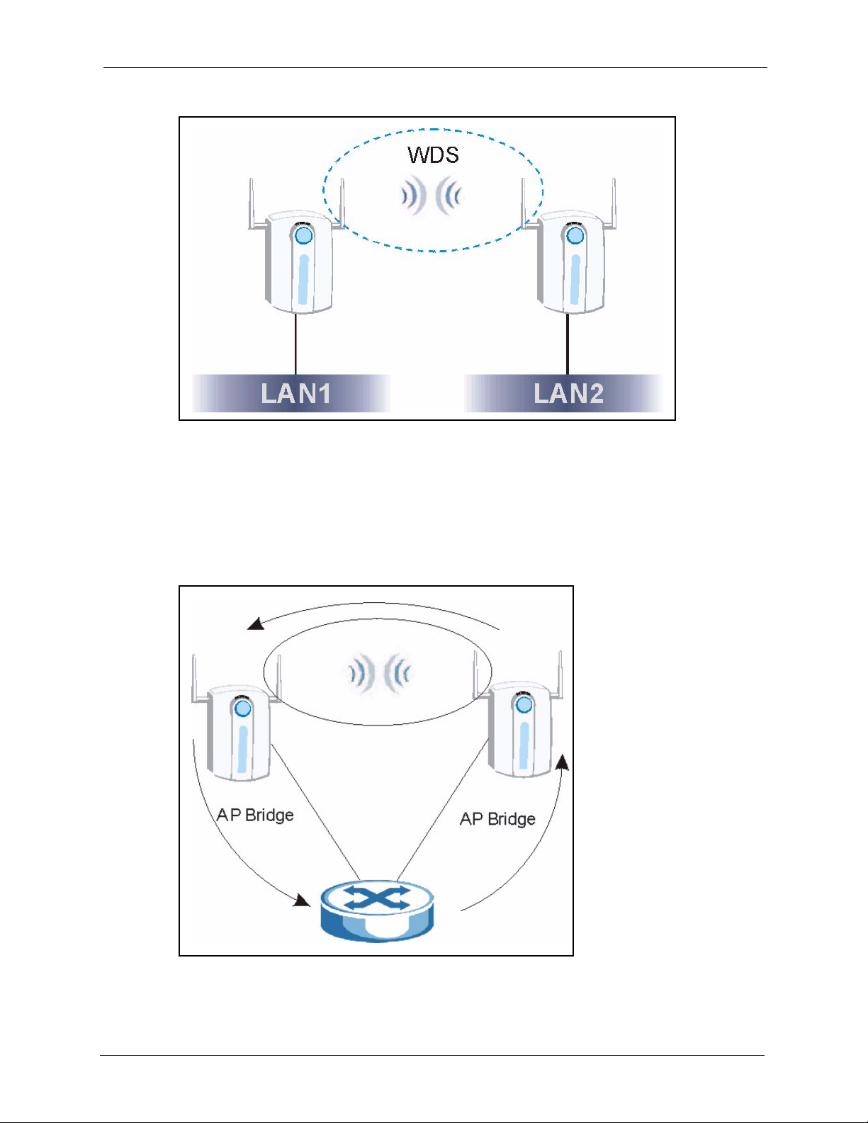
ZyAIR G-3000 User’s Guide
Figure 23 Bridging Example
Be careful to avoid bridge loops when you enable bridging in the ZyAIR. Bridge loops cause
broadcast traffic to circle the network endlessly, resulting in possible throughput degradation
and disruption of communications. The following examples show two network topologies that
can lead to this problem:
If two or more ZyAIRs (in bridge mode) are connected to the same hub as shown next.
Figure 24 Bridge Loop: Two Bridges Connected to Hub
If your ZyAIR (in bridge mode) is connected to a wired LAN while communicating with
another wireless bridge that is also connected to the same wired LAN as shown next.
Chapter 5 Wireless Configuration and Roaming 66
Page 68
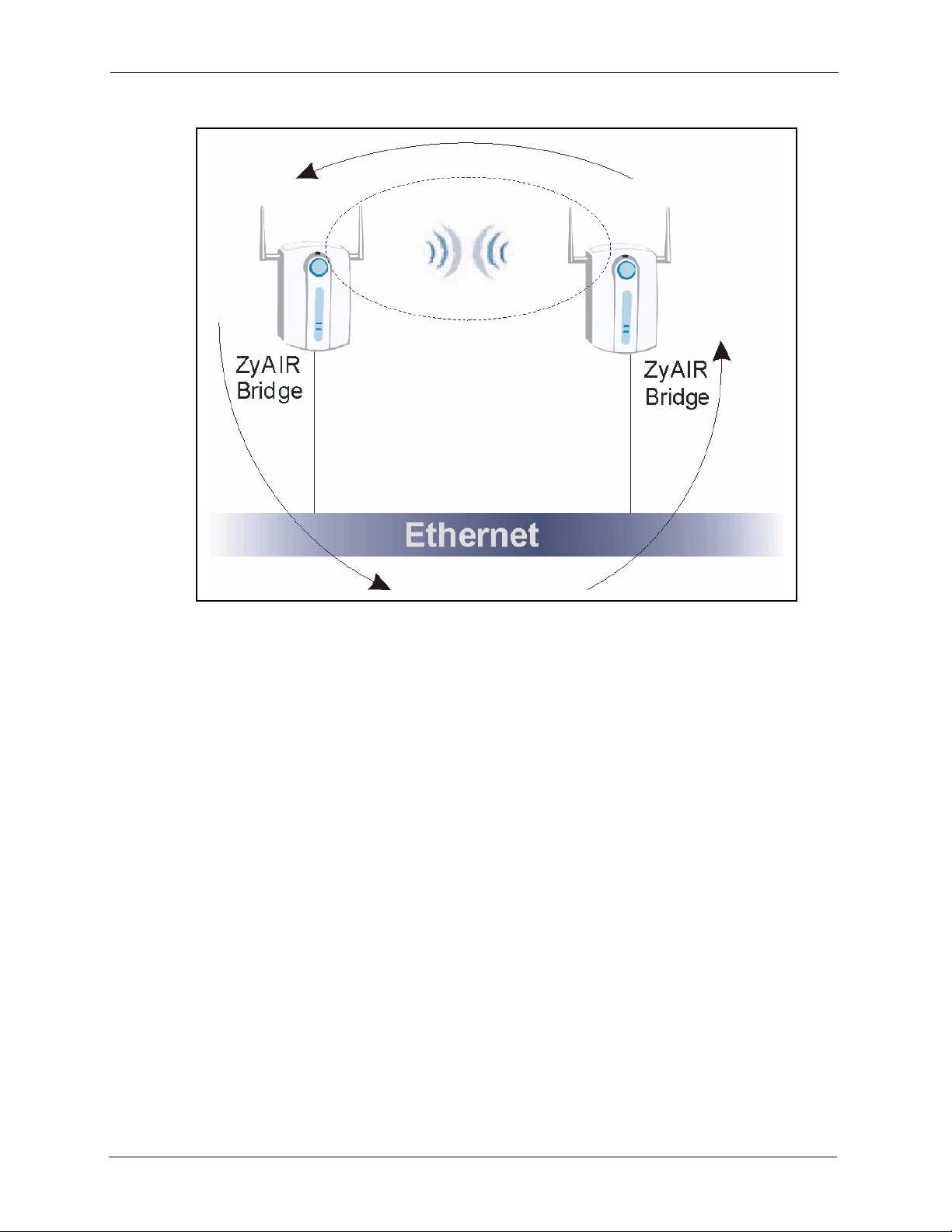
ZyAIR G-3000 User’s Guide
Figure 25 Bridge Loop: Bridge Connected to Wired LAN
To prevent bridge loops, ensure that you enable STP in the Wireless screen or your ZyAIR is
not set to bridge mode while connected to both wired and wireless segments of the same LAN.
Click the WIRELESS link under ADVANCED. Select Bridge/Repeater Operating Mode
to have the ZyAIR act as a wireless bridge only.
67 Chapter 5 Wireless Configuration and Roaming
Page 69
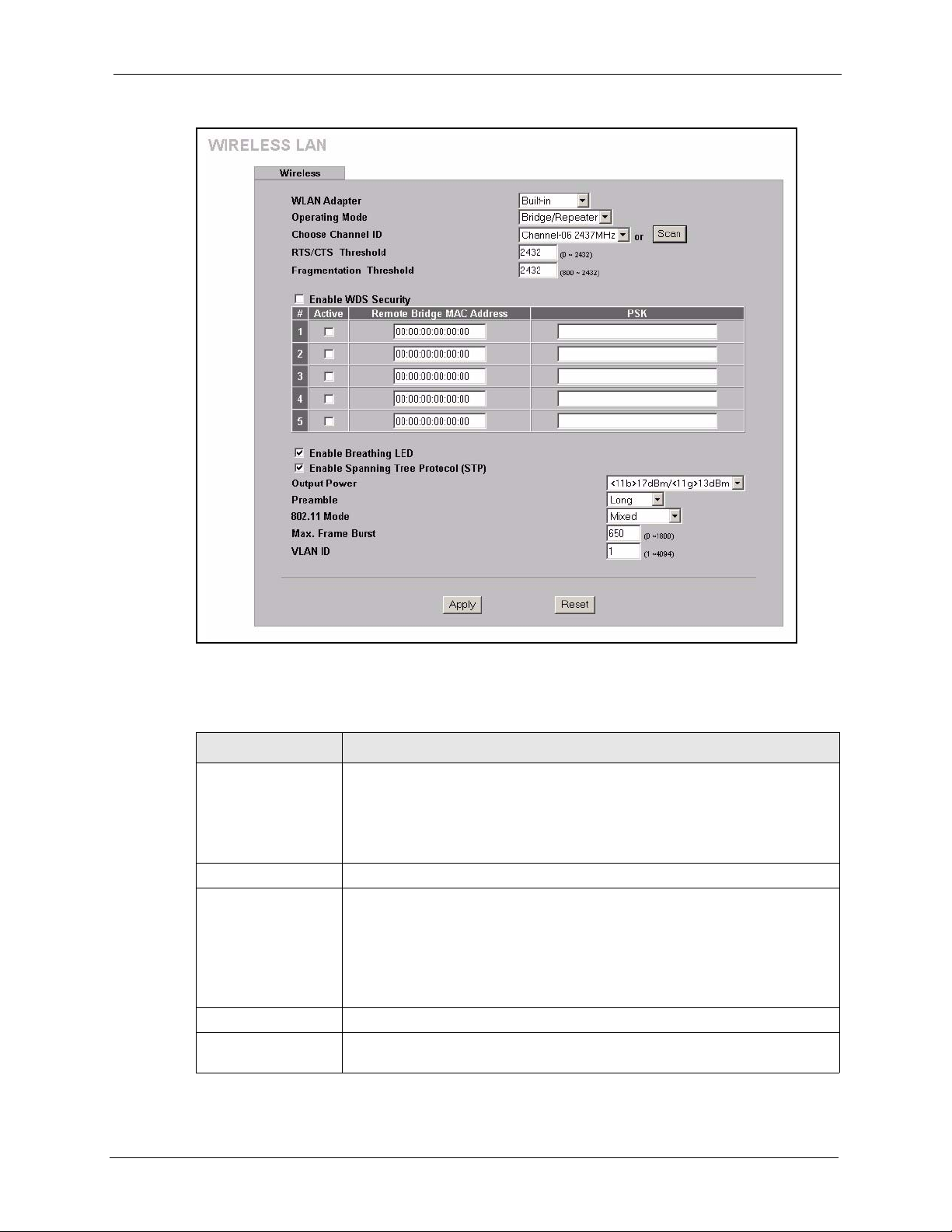
Figure 26 Wireless : Bridge/Repeater
ZyAIR G-3000 User’s Guide
The following table describes the bridge labels in this screen.
Table 13 Wireless : Bridge/Repeater
LABEL DESCRIPTIONS
WLAN Adaptor Select Built-in from the drop down list box to configure your ZyAIR using the
internal WLAN card. Select Removable from the drop down list box to
configure your ZyAIR using a WLAN card adapter using the extension card slot.
Note: This field is only available when you have an external
wireless card inserted in the ZyAIR.
Operating Mode Select Bridge/Repeater in this field to display the screen as shown.
Enable WDS Security Select the check box to enable WDS on your ZyAIR. A Wireless Distribution
System (WDS) is a wireless connection between two or more APs.
When you select the check box, you are prompted to type a Pre-Shared Key
(PSK). The ZyAIR uses TKIP to encrypt traffic on the WDS between AP’s.
Note: Other AP’s must use the same encryption method to
enable WDS.
# This is the index number of the bridge connection.
Active Select the check box to enable the bridge connection. Otherwise, clear the
check box to disable it.
Chapter 5 Wireless Configuration and Roaming 68
Page 70

ZyAIR G-3000 User’s Guide
Table 13 Wireless : Bridge/Repeater
LABEL DESCRIPTIONS
Remote Bridge MAC
Address
PSK Type a pre-shared key from 8 to 63 case-sensitive ASCII characters (including
See the Wireless Security chapter for information on the other labels in this screen.
5.5.3 AP+Bridge Mode
Click the WIRELESS link under ADVANCED. Select AP+Bridge in the Operating Mode
drop-down list box to display the screen as shown next. In this screen, you can configure the
ZyAIR to function as an AP and bridge simultaneously. See the section on ZyAIR applications
for more information.
Type the MAC address of the peer device in a valid MAC address format, that
is, six hexadecimal character pairs, for example, 12:34:56:78:9a:bc.
spaces and symbols).
69 Chapter 5 Wireless Configuration and Roaming
Page 71
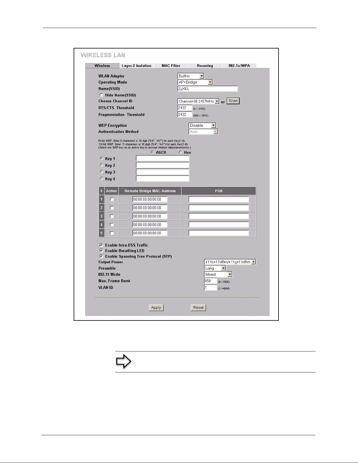
Figure 27 Wireless: AP+Bridge
ZyAIR G-3000 User’s Guide
See the tables describing the fields in the Access Point and Bridge/Repeater operating modes
for descriptions of the fields in this screen.
Note: The following screens are configurable only in Access
Point and AP+Bridge operating modes.
Chapter 5 Wireless Configuration and Roaming 70
Page 72

ZyAIR G-3000 User’s Guide
5.6 Configuring Roaming
A wireless station is a device with an IEEE 802.11b or an IEEE 802.11g compliant wireless
inteface. An access point (AP) acts as a bridge between the wireless and wired networks. An
AP creates its own wireless coverage area. A wireless station can associate with a particular
access point only if it is within the access point’s coverage area.
In a network environment with multiple access points, wireless stations are able to switch from
one access point to another as they move between the coverage areas. This is roaming. As the
wireless station moves from place to place, it is responsible for choosing the most appropriate
access point depending on the signal strength, network utilization or other factors.
The roaming feature on the access points allows the access points to relay information about
the wireless stations to each other. When a wireless station moves from a coverage area to
another, it scans and uses the channel of a new access point, which then informs the access
points on the LAN about the change. The new information is then propagated to the other
access points on the LAN. An example is shown in
With roaming, a wireless LAN mobile user enjoys a continuous connection to the wired
network through an access point while moving around the wireless LAN.
Figure 28.
Enable roaming to exchange the latest bridge information of all wireless stations between APs
when a wireless station moves between coverage areas. Wireless stations can still associate
with other APs even if you disable roaming. Enabling roaming ensures correct traffic
forwarding (bridge tables are updated) and maximum AP efficiency. The AP deletes records
of wireless stations that associate with other APs (Non-ZyXEL APs may not be able to
perform this). 802.1x authentication information is not exchanged (at the time of writing).
71 Chapter 5 Wireless Configuration and Roaming
Page 73

Figure 28 Roaming Example
ZyAIR G-3000 User’s Guide
The steps below describe the roaming process.
1 As wireless station Y moves from the coverage area of access point AP 1 to that of access
point
2 AP 2, it scans and uses the signal of access point AP 2.
3 Access point AP 2 acknowledges the presence of wireless station Y and relays this
information to access point AP 1 through the wired LAN.
4 Access point AP 1 updates the new position of wireless station.
5 Wireless station Y sends a request to access point AP 2 for reauthentication.
5.6.1 Requirements for Roaming
The following requirements must be met in order for wireless stations to roam between the
coverage areas.
1 All the access points must be on the same subnet and configured with the same ESSID.
2 If IEEE 802.1x user authentication is enabled and to be done locally on the access point,
the new access point must have the user profile for the wireless station.
3 The adjacent access points should use different radio channels when their coverage areas
overlap.
4 All access points must use the same port number to relay roaming information.
5 The access points must be connected to the Ethernet and be able to get IP addresses from
a DHCP server if using dynamic IP address assignment.
Chapter 5 Wireless Configuration and Roaming 72
Page 74

ZyAIR G-3000 User’s Guide
To enable roaming on your ZyAIR, click the WIRELESS link under ADVANCED and then
the Roaming tab. The screen appears as shown.
Figure 29 Roaming
The following table describes the labels in this screen.
Table 14 Roaming
LABEL DESCRIPTION
Active Select Yes from the drop-down list box to enable roaming on the ZyAIR if you
have two or more ZyAIRs on the same subnet.
Note: All APs on the same subnet and the wireless stations must
have the same SSID to allow roaming.
Port # Enter the port number to communicate roaming information between access
Apply Click Apply to save your changes back to the ZyAIR.
Reset Click Reset to begin configuring this screen afresh.
points. The port number must be the same on all access points. The default is
3517. Make sure this port is not used by other services.
73 Chapter 5 Wireless Configuration and Roaming
Page 75
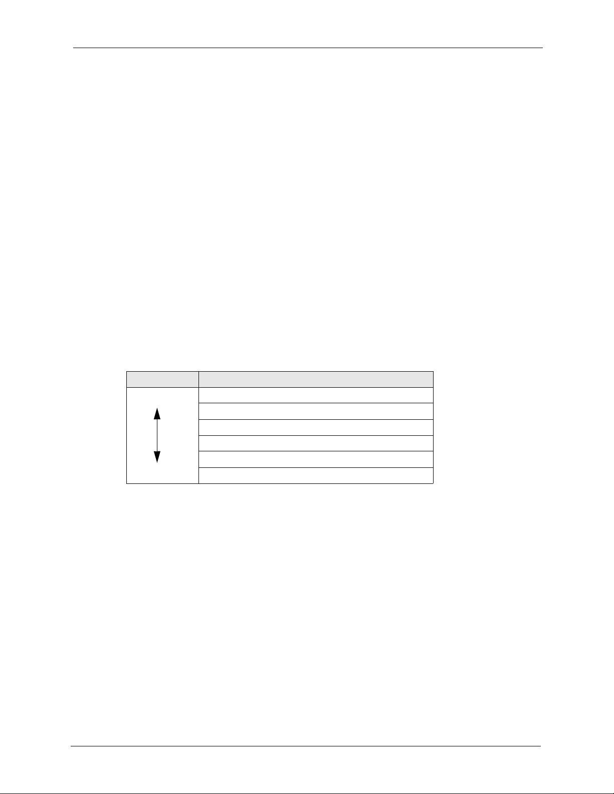
Wireless Security
This chapter describes how to use the MAC Filter, 802.1x, Local User Database and RADIUS
to configure wireless security on your ZyAIR.
6.1 Wireless Security Overview
Wireless security is vital to your network to protect wireless communication between wireless
stations, access points and the wired network.
The figure below shows the possible wireless security levels on your ZyAIR. EAP (Extensible
Authentication Protocol) is used for authentication and utilizes dynamic WEP key exchange. It
requires interaction with a RADIUS (Remote Authentication Dial-In User Service) server
either on the WAN or your LAN to provide authentication service for wireless stations
ZyAIR G-3000 User’s Guide
CHAPTER 6
Table 15 ZyAIR Wireless Security Levels
Security Level Security Type
Least Secure
Most Secure
If you do not enable any wireless security on your ZyAIR, your network is accessible to any
wireless networking device that is within range.
Unique SSID (Default)
Unique SSID with Hide SSID Enabled
MAC Address Filtering
WEP Encryption
IEEE802.1x EAP with RADIUS Server Authentication
Wi-Fi Protected Access (WPA)
6.2 WEP Overview
WEP (Wired Equivalent Privacy) as specified in the IEEE 802.11 standard provides methods
for both data encryption and wireless station authentication.
6.2.1 Data Encryption
WEP provides a mechanism for encrypting data using encryption keys. Both the AP and the
wireless stations must use the same WEP key to encrypt and decrypt data. Your ZyAIR allows
you to configure up to four 64-bit or 128-bit WEP keys, but only one key can be enabled at
any one time.
Chapter 6 Wireless Security 74
Page 76

ZyAIR G-3000 User’s Guide
6.2.2 Authentication
Three different methods can be used to authenticate wireless stations to the network: Open
System, Shared Key, and Auto. The following figure illustrates the steps involved.
Figure 30 WEP Authentication Steps
Open system authentication involves an unencrypted two-message procedure. A wireless
station sends an open system authentication request to the AP, which will then automatically
accept and connect the wireless station to the network. In effect, open system is not
authentication at all as any station can gain access to the network.
Shared key authentication involves a four-message procedure. A wireless station sends a
shared key authentication request to the AP, which will then reply with a challenge text
message. The wireless station must then use the AP’s default WEP key to encrypt the
challenge text and return it to the AP, which attempts to decrypt the message using the AP’s
default WEP key. If the decrypted message matches the challenge text, the wireless station is
authenticated.
When your ZyAIR's authentication method is set to open system, it will only accept open
system authentication requests. The same is true for shared key authentication. However,
when it is set to auto authentication, the ZyAIR will accept either type of authentication
request and the ZyAIR will fall back to use open authentication if the shared key does not
match.
75 Chapter 6 Wireless Security
Page 77

6.3 Configuring WEP Encryption
In order to configure and enable WEP encryption; click the WIRELESS link under
ADVANCED to display the Wireless screen.
Note: The WEP Encryption, Authentication Method and the
WEP key fields are not visible when you enable Dynamic WEP
Key, WPA or WPA-PSK in the 802.1x/WPA screen.
Figure 31 Wireless
ZyAIR G-3000 User’s Guide
The following table describes the wireless LAN security labels in this screen.
Chapter 6 Wireless Security 76
Page 78

ZyAIR G-3000 User’s Guide
Table 16 Wireless
LABEL DESCRIPTION
WEP Encryption Select Disable to allow wireless stations to communicate with the access
Authentication
Method
ASCII Select this option to enter ASCII characters as the WEP keys.
Hex Select this option to enter hexadecimal characters as the WEP keys.
Key 1 to
Key 4
Enable Intra-BSS
Traffic
Enable Breathing
LED
Enable Spanning
Tree Control (STP)
Output Power Set the output power of the ZyAIR in this field. If there is a high density of APs
Preamble Select a preamble type from the drop-down list menu. Choices are Long, Short
points without any data encryption.
Select 64-bit WEP or 128-bit WEP to enable data encryption.
Select Auto, Open System or Shared Key from the drop-down list box.
This field is N/A if WEP is not activated.
If WEP encryption is activated, the default setting is Auto.
The preceding “0x” is entered automatically.
The WEP keys are used to encrypt data. Both the ZyAIR and the wireless
stations must use the same WEP key for data transmission.
If you chose 64-bit WEP, then enter any 5 ASCII characters or 10 hexadecimal
characters ("0-9", "A-F").
If you chose 128-bit WEP, then enter 13 ASCII characters or 26 hexadecimal
characters ("0-9", "A-F").
You must configure all four keys, but only one key can be activated at any one
time. The default key is key 1.
Intra-BSS traffic is traffic between wireless stations in the same BSS. Select
this check box to enable Intra-BSS traffic.
Select this check box to enable the Breathing LED, also known as the ZyAIR
LED.
The blue ZyAIR LED is on when the ZyAIR is on and blinks (or breaths) when
data is being transmitted to/from its wireless stations. Clear the check box to
turn this LED off even when the ZyAIR is on and data is being transmitted/
received.
(R)STP detects and breaks network loops and provides backup links between
switches, bridges or routers. It allows a bridge to interact with other (R)STP compliant bridges in your network to ensure that only one path exists between
any two stations on the network. Select the check box to activate STP on the
ZyAIR.
within an area, decrease the output power of the ZyAIR to reduce interference
with other APs. Select one of the following:
• <11b>17dBm/<11g>13dBm (<11b>50mW/<11g>20mW)
• <11b>15dBm/<11g>11dBm (<11b>32mW/<11g>12.6mW)
• <11b>13dBm/<11g>9dBm (<11b>20mW/<11g>7.9mW)
• <11b>11dBm/<11g>7dBm (<11b>12.6m W/ <11 g>5mW)
• <11b>7dBm/<11g>3dBm (<11b>5mW/<11g>2mW)
and Dynamic. The default setting is Long.
See the section on preamble for more information.
77 Chapter 6 Wireless Security
Page 79

ZyAIR G-3000 User’s Guide
Table 16 Wireless
LABEL DESCRIPTION
802.11 Mode Select 802.11b Only to allow only IEEE 802.11b compliant WLAN devices to
associate with the ZyAIR.
Select 802.11g Only to allow only IEEE 802.11g compliant WLAN devices to
associate with the ZyAIR.
Select Mixed to allow either IEEE802.11b or IEEE802.11g compliant WLAN
devices to associate with the ZyAIR. The transmission rate of your ZyAIR might
be reduced.
Max. Frame Burst Enable Maximum Frame Burst to help eliminate collisions in mixed-mode
networks (networks with both IEEE 802.11g and IEEE 802.11b traffic) and
enhance the performance of both pure IEEE 802.11g and mixed IEEE 802.11b/
g networks. Maximum Frame Burst sets the maximum time, in microseconds,
that the ZyAIR transmits IEEE 802.11g wireless traffic only.
Type the maximum frame burst between 0 and 1800 (650, 1000 or 1800
recommended). Enter 0 to disable this feature.
VLAN ID Enter a number from 1 to 4094 to define this VLAN group. At least one device in
Apply Click Apply to save your changes back to the ZyAIR.
Reset Click Reset to begin configuring this screen afresh.
your network must belong to this VLAN group in order to manage the ZyAIR.
6.4 Layer-2 Isolation Introduction
Layer-2 isolation is used to prevent wireless clients associated with your ZyAIR from
communicating with other wireless clients, AP’s, computers or routers in a network.
In the following figure, A represents your ZyAIR, B represents an AP, C represents a server
and 1, 2 and 3 represent wireless clients. If layer-2 isolation is enabled on the ZyAIR (A), then
wireless clients 1 and 2 cannot communicate with B, C or 3. Wireless clients 1 and 2 cannot
communicate with each other unless you enable Intra-BSS in the Wireless configuration
screen.
Note: In the Wireless configuration screen, the Enable Intra-BSS
Traffic check box is cleared when you enable layer-2 isolation.
If you want 1 and 2 to be able to communicate with C, B and/ or 3 then enter the MAC
addresses of C, B and/or 3 in the Allow devices with these MAC addresses table.
Chapter 6 Wireless Security 78
Page 80
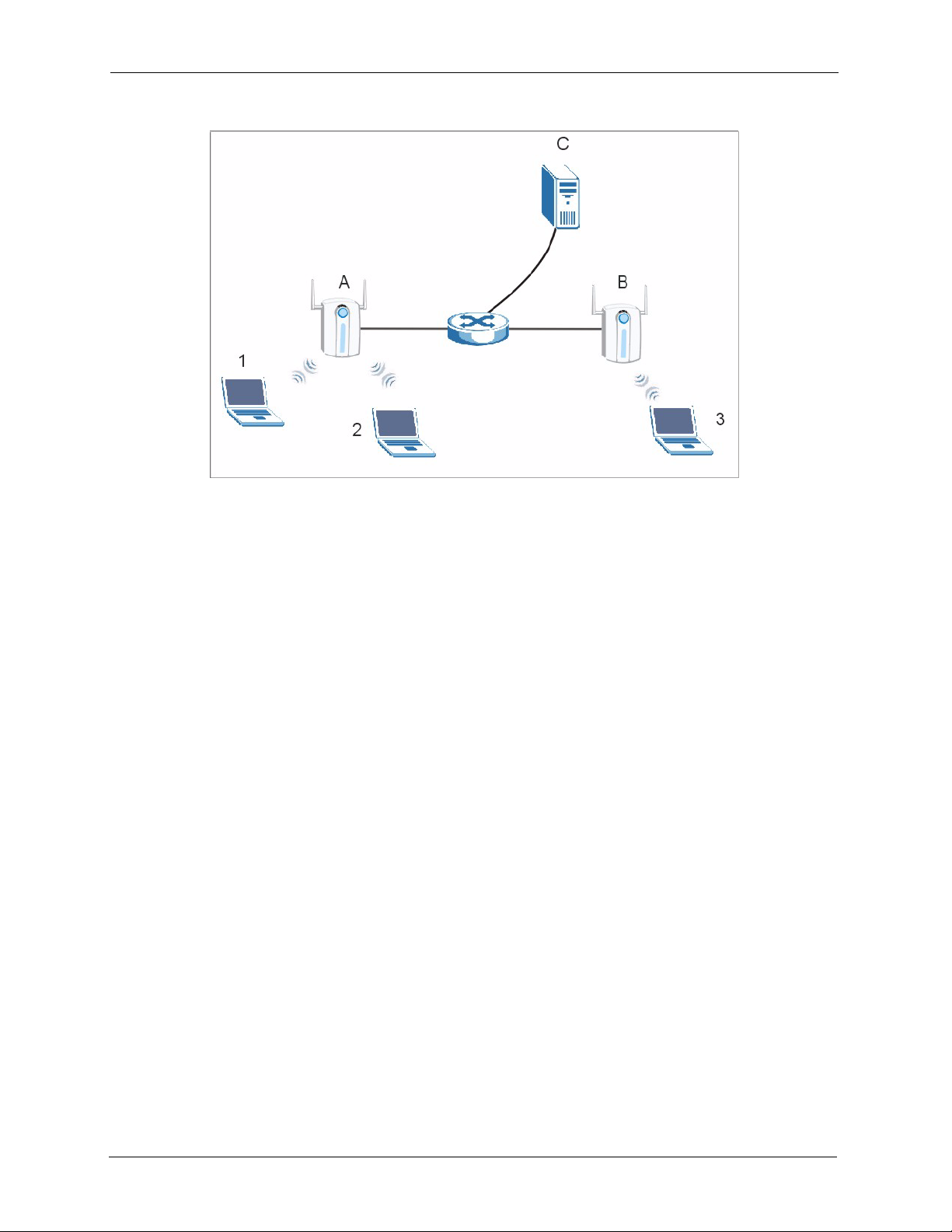
ZyAIR G-3000 User’s Guide
Figure 32 Layer-2 Isolation Application
MAC addresses that are not listed in the Allow devices with these MAC addresses table are
blocked from communicating with the ZyAIR’s wireless clients except for broadcast packets.
Layer-2 isolation does not check the traffic between wireless clients that are associated with
the same AP. Intra-BSS Traffic allows wireless clients associated with the same AP to
communicate with each other.
6.5 Layer-2 Isolation Configuration
If layer-2 isolation is enabled, you need to know the MAC address of the wireless client, AP,
computer or router that you want to allow to communicate with the ZyAIR's wireless clients.
To configure layer-2 isolation, click the WIRELESS link under ADVANCED and then the
Layer-2 Isolation tab. The screen appears as shown next.
79 Chapter 6 Wireless Security
Page 81
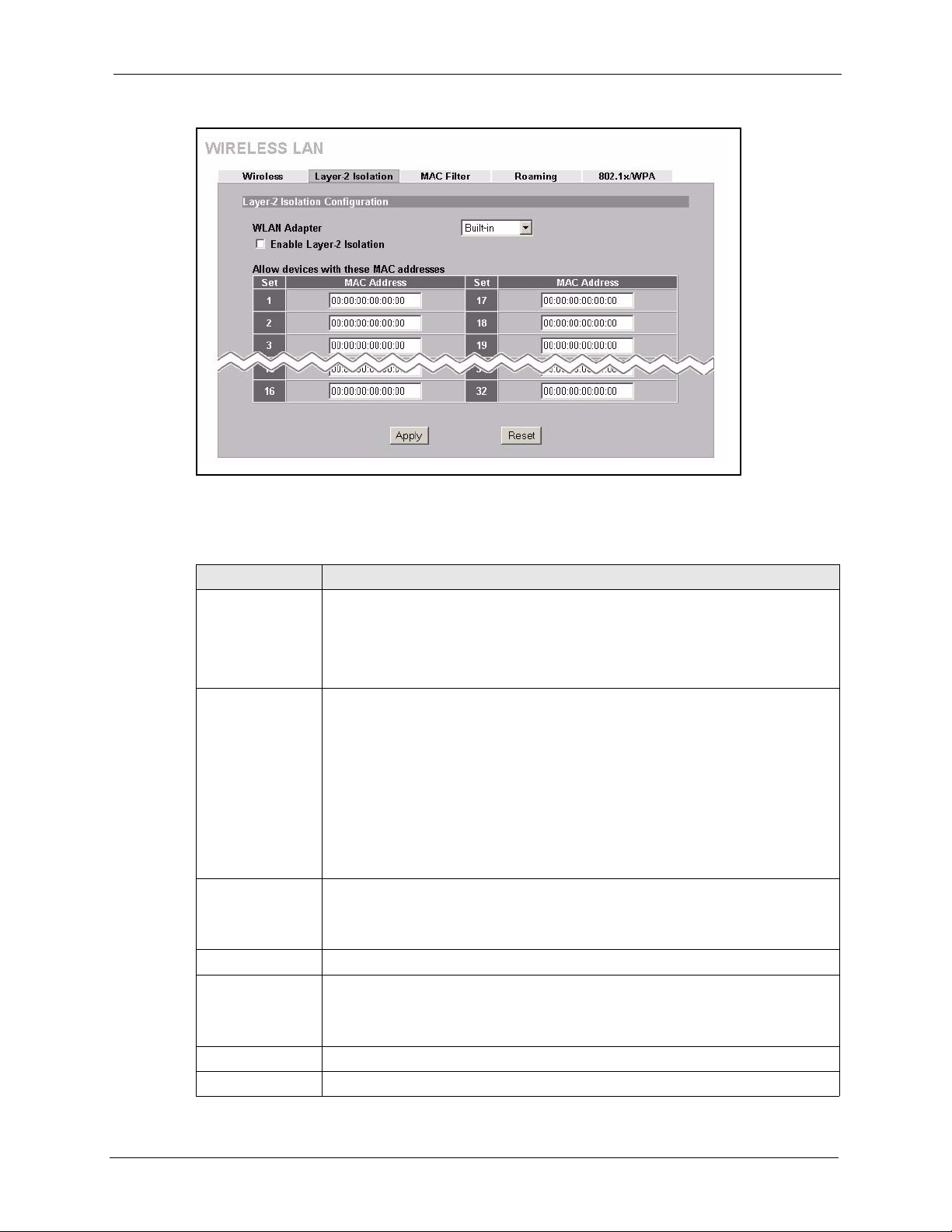
Figure 33 Layer-2 Isolation Configuration Screen
The following table describes the labels in this screen.
ZyAIR G-3000 User’s Guide
Table 17 Layer-2 Isolation Configuration
LABEL DESCRIPTION
WLAN Adaptor Select Built-in from the drop down list box to configure your ZyAIR using the
internal WLAN card. Select Removable from the drop down list box to configure
your ZyAIR using a WLAN card adapter using the extension card slot.
Note: This field is only available when you have an external
wireless card inserted in the ZyAIR.
Enable Layer-2
Isolation
Allow devices with
these MAC
addresses
Set This is the index number of the MAC address.
MAC Address Type the MAC addresses of the wireless client, AP, computer or router that you
Apply Click Apply to save your changes back to the ZyAIR.
Reset Click Reset to begin configuring this screen afresh.
Select the Enable Layer-2 Isolation check box to enable layer-2 isolation on the
ZyAIR.
When you select the Enable Layer-2 Isolation check box and save this
configuration screen, the Enable Intra-BSS Traffic check box in the Wireless
configuration screen is cleared. This means that wireless clients connected to the
ZyAIR cannot communicate with one another. This would be appropriate in a
hotspot application, for example, in a hotel where wireless clients can access the
Internet, but cannot communicate with other wireless clients or AP’s.
If you want wireless clients associated with the ZyAIR to be able to communicate
with each other, you must select the Enable Intra-BSS Traffic check box in the
Wireless configuration screen.
These are the MAC address of a wireless client, AP, computer or router. A wireless
client associated with the ZyAIR can communicate with another wireless client, AP,
computer or router only if the MAC addresses of those devices are listed in this
table.
want to allow the ZyAIR associated wireless clients to have access to in these
address fields. Type the MAC address in a valid MAC address format, that is, six
hexadecimal character pairs, for example, 12:34:56:78:9a:bc.
Chapter 6 Wireless Security 80
Page 82

ZyAIR G-3000 User’s Guide
6.5.1 Layer-2 Isolation Examples
The following section shows you example layer-2 isolation configurations on the ZyAIR (A).
Figure 34
Layer-2 Isolation Example
00:0a:c5:00:00:66
00:0a:c5:00:00:cc
6.5.2 Layer-2 Isolation Example 1
In the following example wireless clients 1 and 2 cannot communicate with C, B or 3.
• Select the Enable Layer-2 Isolation check box, but do not configure any MAC
addresses in the Allow devices with these MAC addresses table (1 and 2 cannot
communicate with each other unless you enable Intra-BSS).
81 Chapter 6 Wireless Security
Page 83
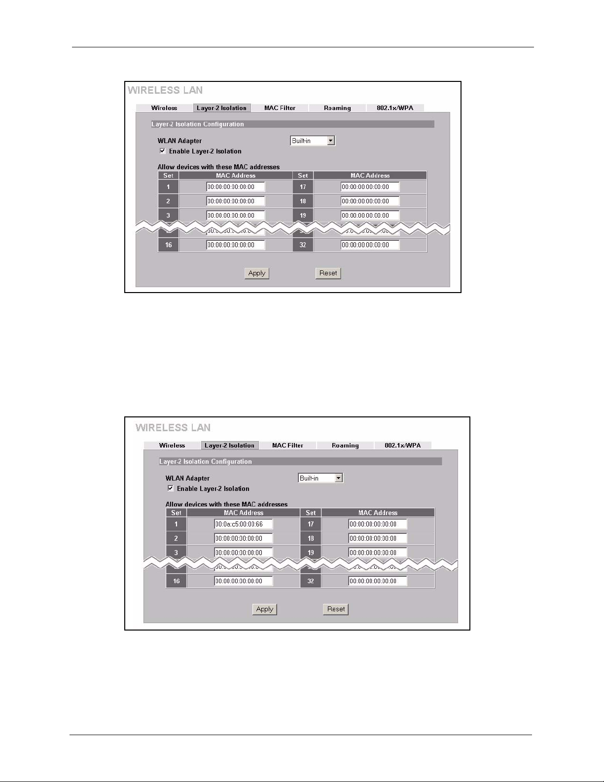
Figure 35 Layer-2 Isolation Example 1
6.5.3 Layer-2 Isolation Example 2
ZyAIR G-3000 User’s Guide
In the following example wireless clients 1 and 2 can communicate with C, but not B or 3.
• Select the Enable Layer-2 Isolation check box.
• Enter C’s MAC address in the Allow devices with these MAC addresses field.
Figure 36 Layer-2 Isolation Example 2
6.5.4 Layer-2 Isolation Example 3
In the following example wireless clients 1 and 2 can communicate with B and C but not 3.
Chapter 6 Wireless Security 82
Page 84

ZyAIR G-3000 User’s Guide
• Select the Enable Layer-2 Isolation check box.
• Configure more than one MAC address. Enter the server and your ZyAIR MAC
addresses in the Allow devices with these MAC addresses fields.
Figure 37 Layer-2 Isolation Example 3
6.6 MAC Filter
The MAC filter screen allows you to configure the ZyAIR to give exclusive access to up to 32
devices (Allow Association) or exclude up to 32 devices from accessing the ZyAIR (Deny
Association). Every Ethernet device has a unique MAC (Media Access Control) address. The
MAC address is assigned at the factory and consists of six pairs of hexadecimal characters, for
example, 00:A0:C5:00:00:02. You need to know the MAC address of the devices to configure
this screen.
The WLAN Adapter drop down list box is only available when you have an external wireless
card inserted in the ZyAIR. No matter whether you select Built-in or Removable, the
configuration screens are the same for each interface.
To change your ZyAIR’s MAC filter settings, click the WIRELESS link under ADVANCED
and then the MAC Filter tab. The screen appears as shown.
83 Chapter 6 Wireless Security
Page 85

Figure 38 MAC Address Filter
ZyAIR G-3000 User’s Guide
The following table describes the labels in this screen.
Table 18 MAC Address Filter
LABEL DESCRIPTION
WLAN Adapter Select Built-in from the drop down list box to configure your ZyAIR using the
internal WLAN card. Select Removable from the drop down list box to configure
your ZyAIR using a WLAN card adapter using the extension card slot.
Note: This field is only available when you have an external
wireless card inserted in the ZyAIR.
Active Select Yes from the drop down list box to enable MAC address filtering.
Filter Action Define the filter action for the list of MAC addresses in the MAC address filter
table.
Select Deny Association to block access to the router, MAC addresses not
listed will be allowed to access the router.
Select Allow Association to permit access to the router, MAC addresses not
listed will be denied access to the router.
MAC Address Enter the MAC addresses (in XX:XX:XX:XX:XX:XX format) of the wireless
station that are allowed or denied access to the ZyAIR in these address fields.
Chapter 6 Wireless Security 84
Page 86

ZyAIR G-3000 User’s Guide
Table 18 MAC Address Filter
LABEL DESCRIPTION
Apply Click Apply to save your changes back to the ZyAIR.
Reset Click Reset to begin configuring this screen afresh.
6.7 802.1x Overview
The IEEE 802.1x standard outlines enhanced security methods for both the authentication of
wireless stations and encryption key management. Authentication can be done using the local
user database internal to the ZyAIR (authenticate up to 32 users) or an external RADIUS
server for an unlimited number of users.
6.8 Introduction to RADIUS
RADIUS is based on a client-sever model that supports authentication and accounting, where
access point is the client and the server is the RADIUS server. The RADIUS server handles
the following tasks among others:
• Authentication
Determines the identity of the users.
• Accounting
Keeps track of the client’s network activity.
RADIUS user is a simple package exchange in which your ZyAIR acts as a message relay
between the wireless station and the network RADIUS server.
6.8.1 Types of RADIUS Messages
The following types of RADIUS messages are exchanged between the access point and the
RADIUS server for user authentication:
• Access-Request
Sent by an access point, requesting authentication.
• Access-Reject
Sent by a RADIUS server rejecting access.
• Access-Accept
Sent by a RADIUS server allowing access.
• Access-Challenge
85 Chapter 6 Wireless Security
Page 87

ZyAIR G-3000 User’s Guide
Sent by a RADIUS server requesting more information in order to allow access. The
access point sends a proper response from the user and then sends another AccessRequest message.
The following types of RADIUS messages are exchanged between the access point and the
RADIUS server for user accounting:
• Accounting-Request
Sent by the access point requesting accounting.
• Accounting-Response
Sent by the RADIUS server to indicate that it has started or stopped accounting.
In order to ensure network security, the access point and the RADIUS server use a shared
secret key, which is a password, they both know. The key is not sent over the network. In
addition to the shared key, password information exchanged is also encrypted to protect the
wired network from unauthorized access.
6.9 EAP Authentication Overview
EAP (Extensible Authentication Protocol) is an authentication protocol that runs on top of the
IEEE802.1x transport mechanism in order to support multiple types of user authentication. By
using EAP to interact with an EAP-compatible RADIUS server, the access point helps a
wireless station and a RADIUS server perform authentication.
The type of authentication you use depends on the RADIUS server or the AP. The ZyAIR
supports EAP-TLS, EAP-TTLS, EAP-MD5 and PEAP with RADIUS. Refer to the Types of
EAP Authentication appendix for descriptions on the common types.
Your ZyAIR supports EAP-MD5 (Message-Digest Algorithm 5) and PEAP (Protected EAP)
with the built-in RADIUS server.
The following figure shows an overview of authentication when you specify a RADIUS server
on your access point.
Figure 39 EAP Authentication
The details below provide a general description of how IEEE 802.1x EAP authentication
works. For an example list of EAP-MD5 authentication steps, see the IEEE 802.1x appendix.
Chapter 6 Wireless Security 86
Page 88

ZyAIR G-3000 User’s Guide
1 The wireless station sends a “start” message to the ZyAIR.
2 The ZyAIR sends a “request identity” message to the wireless station for identity
information.
3 The wireless station replies with identity information, including username and password.
4 The RADIUS server checks the user information against its user profile database and
determines whether or not to authenticate the wireless station.
6.10 Dynamic WEP Key Exchange
The AP maps a unique key that is generated with the RADIUS server. This key expires when
the wireless connection times out, disconnects or reauthentication times out. A new WEP key
is generated each time reauthentication is performed.
If this feature is enabled, it is not necessary to configure a default WEP encryption key in the
Wireless screen. You may still configure and store keys here, but they will not be used while
Dynamic WEP is enabled.
To use Dynamic WEP, enable and configure the RADIUS server (see Figure 43) and enable
Dynamic WEP Key Exchange in the 802.1x screen. Ensure that the wireless station’s EAP
type is configured to one of the following:
•EAP-TLS
•EAP-TTLS
• PEAP
Note: EAP-MD5 cannot be used with Dynamic WEP Key
Exchange.
6.11 Introduction to WPA
Wi-Fi Protected Access (WPA) is a subset of the IEEE 802.11i standard. Key differences
between WPA and WEP are user authentication and improved data encryption.
6.11.1 User Authentication
WPA applies IEEE 802.1x and Extensible Authentication Protocol (EAP) to authenticate
wireless clients using
page 100 for for more information on authentication of Trusted User’s. See later in this
chapter and the appendices for more information on IEEE 802.1x, RADIUS, EAP and PEAP.
an external RADIUS database. See Internal RADIUS Server on
87 Chapter 6 Wireless Security
Page 89

If you don’t have an external RADIUS server you should use WPA-PSK (WPA -Pre-Shared
Key) that only requires a single (identical) password entered into each access point, wireless
gateway and wireless client. As long as the passwords match, a client will be granted access to
a WLAN.
6.11.2 Encryption
WPA improves data encryption by using Temporal Key Integrity Protocol (TKIP), Message
Integrity Check (MIC) and IEEE 802.1x.
Temporal Key Integrity Protocol (TKIP) uses 128-bit keys that are dynamically generated and
distributed by the authentication server. It includes a per-packet key mixing function, a
Message Integrity Check (MIC) named Michael, an extended initialization vector (IV) with
sequencing rules, and a re-keying mechanism.
TKIP regularly changes and rotates the encryption keys so that the same encryption key is
never used twice.
AP that then sets up a key hierarchy and management system, using the pair-wise key to
dynamically generate unique data encryption keys to encrypt every data packet that is
wirelessly communicated between the AP and the wireless clients. This all happens in the
background automatically.
ZyAIR G-3000 User’s Guide
The RADIUS server distributes a Pairwise Master Key (PMK) key to the
The Message Integrity Check (MIC) is designed to prevent an attacker from capturing data
packets, altering them and resending them. The MIC provides a strong mathematical function
in which the receiver and the transmitter each compute and then compare the MIC. If they do
not match, it is assumed that the data has been tampered with and the packet is dropped.
By generating unique data encryption keys for every data packet and by creating an integrity
checking mechanism (MIC), TKIP makes it much more difficult to decode data on a Wi-Fi
network than WEP, making it difficult for an intruder to break into the network.
The encryption mechanisms used for WPA and WPA-PSK are the same. The only difference
between the two is that WPA-PSK uses a simple common password, instead of user-specific
credentials. The common-password approach makes WPA-PSK susceptible to brute-force
password-guessing attacks but it’s still an improvement over WEP as it employs an easier-touse, consistent, single, alphanumeric password.
6.12 WPA-PSK Application Example
A WPA-PSK application looks as follows.
1 First enter identical passwords into the AP and all wireless clients. The Pre-Shared Key
(PSK) must consist of between 8 and 63 ASCII characters (including spaces and
symbols).
2 The AP checks each client’s password and (only) allows it to join the network if it
matches its password.
Chapter 6 Wireless Security 88
Page 90
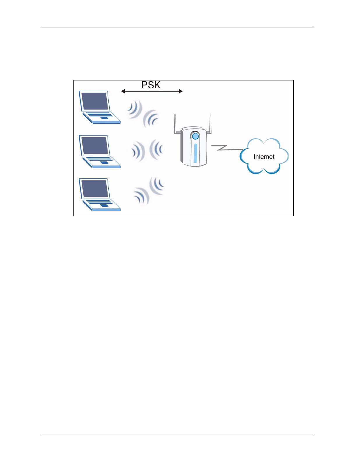
ZyAIR G-3000 User’s Guide
3 The AP derives and distributes keys to the wireless clients.
4 The AP and wireless clients use the TKIP encryption process to encrypt data exchanged
between them.
Figure 40 WPA - PSK Authentication
6.13 WPA with RADIUS Application Example
You need the IP address of the RADIUS server, its port number (default is 1812), and the
RADIUS shared secret. A WPA application example with an external RADIUS server looks
as follows. “A” is the RADIUS server. “DS” is the distribution system.
1 The AP passes the wireless client’s authentication request to the RADIUS server.
2 The RADIUS server then checks the user's identification against its database and grants
or denies network access accordingly.
3 The RADIUS server distributes a Pairwise Master Key (PMK) key to the AP that then
sets up a key hierarchy and management system, using the pair-wise key to dynamically
generate unique data encryption keys to encrypt every data packet that is wirelessly
communicated between the AP and the wireless clients.
89 Chapter 6 Wireless Security
Page 91
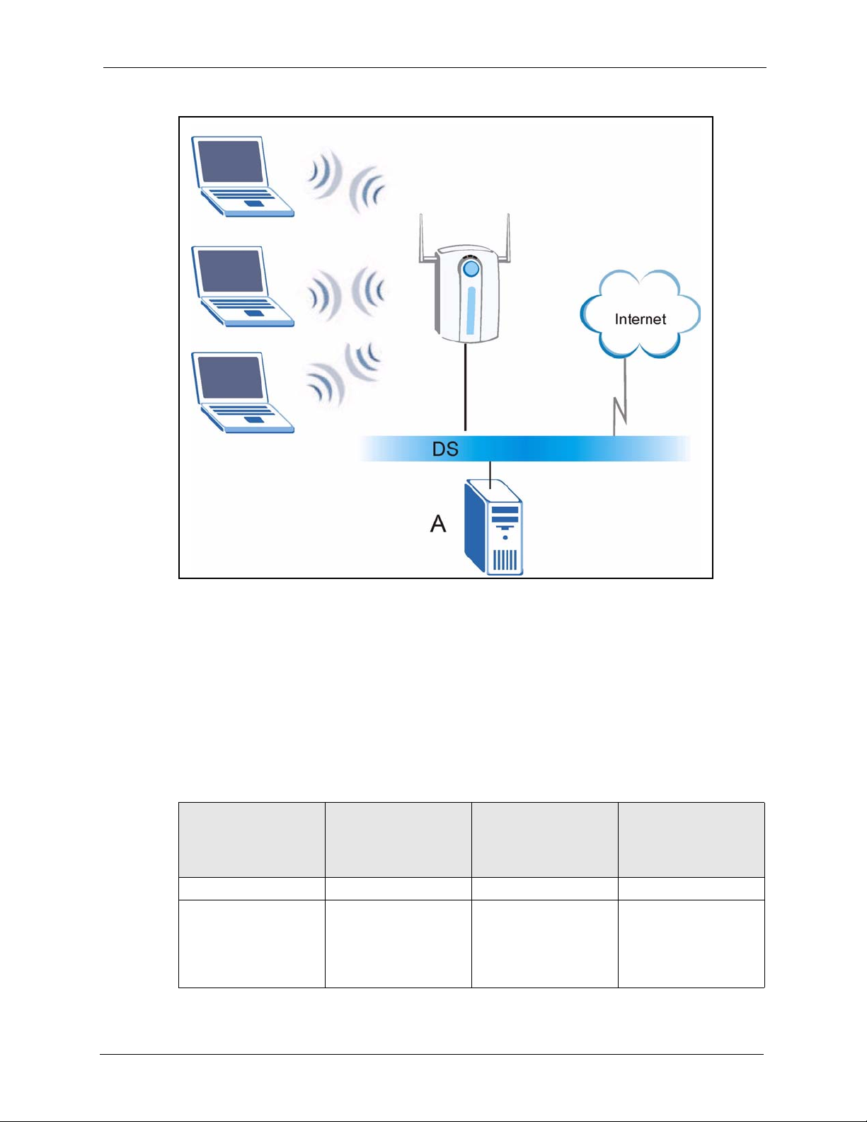
Figure 41 WPA with RADIUS Application Example
ZyAIR G-3000 User’s Guide
6.14 Security Parameters Summary
Refer to this table to see what other security parameters you should configure for each
Authentication Method/ key management protocol type. You enter manual keys by first
selecting 64-bit WEP or 128-bit WEP from the WEP Encryption field and then typing the
keys (in ASCII or hexadecimal format) in the key text boxes. MAC address filters are not
dependent on how you configure these security features.
Table 19 Wireless Security Relational Matrix
AUTHENTICATION
METHOD/ KEY
MANAGEMENT
PROTOCOL
Open None No Disable
Open WEP No
ENCRYPTION
METHOD
ENTER MANUAL KEY IEEE 802.1X
Enable with Dynamic
Y e s
Yes
WEP Key
Enable without Dynamic
WEP Key
Disable
Chapter 6 Wireless Security 90
Page 92

ZyAIR G-3000 User’s Guide
Table 19 Wireless Security Relational Matrix
AUTHENTICATION
METHOD/ KEY
MANAGEMENT
PROTOCOL
ENCRYPTION
METHOD
ENTER MANUAL KEY IEEE 802.1X
Shared WEP No
Yes
Yes
WPA WEP No Enable
WPA TKIP No Enable
WPA-PSK WEP Yes Enable
WPA-PSK TKIP Ye s Enable
6.15 Wireless Client WPA Supplicants
A wireless client supplicant is the software that runs on an operating system instructing the
wireless client how to use WPA. At the time of writing, the most widely available supplicant is
the WPA patch for Windows XP, Funk Software's Odyssey client, and Meetinghouse Data
Communications' AEGIS client.
The Windows XP patch is a free download that adds WPA capability to Windows XP's builtin "Zero Configuration" wireless client. However, you must run Windows XP to use it.
The Funk Software's Odyssey client is bundled free (at the time of writing) with the client
wireless adaptor(s).
Enable with Dynamic
WEP Key
Enable without Dynamic
WEP Key
Disable
6.16 Configuring 802.1x and WPA
To change your ZyAIR’s authentication settings, click the WIRELESS link under
ADVANCED and then the 802.1x/WPA tab. The screen varies by the key management
protocol you select.
You see the next screen when you select No Access Allowed or No Authentication Required
in the Wireless Port Control field.
91 Chapter 6 Wireless Security
Page 93

Figure 42 Wireless LAN : 802.1x/WPA
The following table describes the labels in this screen.
Table 20 Wireless LAN : 802.1x/WPA
LABEL DESCRIPTION
ZyAIR G-3000 User’s Guide
Wireless Port
Control
Apply Click Apply to save your changes back to the ZyAIR.
Reset Click Reset to begin configuring this screen afresh.
To control wireless stations access to the wired network, select a control method
from the drop-down list box. Choose from No Access Allowed, No
Authentication Required and Authentication Required.
No Access Allowed blocks all wireless stations access to the wired network.
No Authentication Required allows all wireless stations access to the wired
network without entering usernames and passwords. This is the default setting.
Authentication Required means that all wireless stations have to enter
usernames and passwords before access to the wired network is allowed.
Select Authentication Required to configure Key Management Protocol and
other related fields.
6.17 Authentication Required : 802.1x
Select Authentication Required in the Wireless Port Control field and 802.1x in the Key
Management Protocol field to display the next screen.
Chapter 6 Wireless Security 92
Page 94
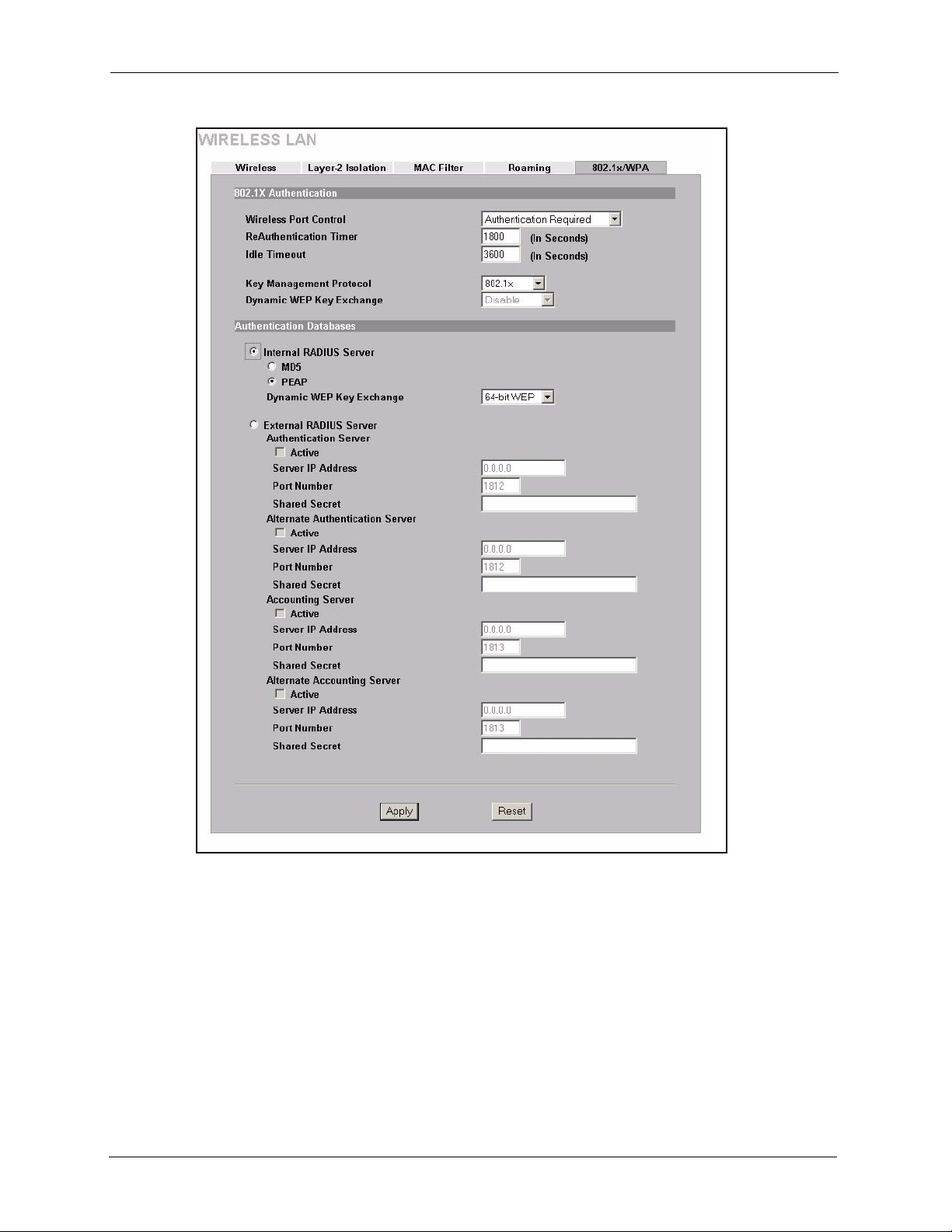
ZyAIR G-3000 User’s Guide
Figure 43 Wireless LAN : 802.1x/WPA for 802.1x Protocol
93 Chapter 6 Wireless Security
Page 95

The following table describes the labels in this screen.
Table 21 Wireless LAN : 802.1x/WPA for 802.1x Protocol
LABEL DESCRIPTION
ZyAIR G-3000 User’s Guide
Wireless Port
Control
ReAuthentication
Timer (In
Seconds)
Idle Timeout
(In Seconds)
Key Management
Protocol
Dynamic WEP
Key Exchange
To control wireless stations access to the wired network, select a control method
from the drop-down list box. Choose from No Authentication Required,
Authentication Required and No Access Allowed.
No Authentication Required allows all wireless stations access to the wired
network without entering usernames and passwords. This is the default setting.
Authentication Required means that all wireless stations have to enter
usernames and passwords before access to the wired network is allowed.
No Access Allowed blocks all wireless stations access to the wired network.
The following fields are only available when you select Authentication Required.
Specify how often wireless stations have to reenter usernames and passwords in
order to stay connected. This field is activated only when you select
Authentication Required in the Wireless Port Control field.
Enter a time interval between 10 and 9999 seconds. The default time interval is
1800 seconds (30 minutes).
Note: If wireless station authentication is done using a RADIUS
server, the reauthentication timer on the RADIUS server has
priority.
The ZyAIR automatically disconnects a wireless station from the wired network
after a period of inactivity. The wireless station needs to enter the username and
password again before access to the wired network is allowed.
This field is activated only when you select Authentication Required in the
Wireless Port Control field. The default time interval is 3600 seconds (or 1 hour).
Choose 802.1x from the drop-down list.
This field is activated only when you select Authentication Required in the
Wireless Port Control field. Also set the Key Management Protocol field to
802.1x.
Select Disable to allow wireless stations to communicate with the access points
without using dynamic WEP key exchange.
Select 64-bit WEP or 128-bit WEP to enable data encryption.
Up to 32 stations can access the ZyAIR when you configure dynamic WEP key
exchange.
This field is not available when you set Key Management Protocol to WPA or
WPA-PSK.
Authentication Databases
Internal RADIUS
Server
Select this radio button to use the ZyAIR’s Internal RADIUS Server.
Select the MD5 radio buttion to use this EAP authentication type to authenticate
other AP’s or wireless clients in other wireless networks.
Select the PEAP radio button to use this EAP authentication type to authenticate
other AP’s or wireless clients in other wireless networks. Use the drop-down list
box to select Disable, 64-bit WEP or 128-bit WEP for Dynamic WEP Exchange.
Note: EAP-MD5 cannot be used with Dynamic WEP Key
Exchange.
For information covering EAP authentication types see Appendix L .
External RADIUS
Server
Chapter 6 Wireless Security 94
Select the radio button to use an External RADIUS Server to authenticate the
ZyAIR’s wireless clients.
Page 96

ZyAIR G-3000 User’s Guide
Table 21 Wireless LAN : 802.1x/WPA for 802.1x Protocol
LABEL DESCRIPTION
Authentication Server
Active Select the check box to enable user authentication through an external
Server IP Address Type the IP address of the external authentication server in dotted decimal
Port Number Type the port number of the external authentication server. The default port
Shared Secret
Alternate
Authentication
Server
authentication server.
notation.
number is 1812.
You need not change this value unless your network administrator instructs you to
do so with additional information.
Type a password (up to 31 alphanumeric characters) as the key to be shared
between the external authentication server and the ZyAIR.
The key must be the same on the external authentication server and your ZyAIR.
The key is not sent over the network.
If the ZyAIR cannot authenticate wireless users using the Authentication Server,
the Alternate Authentication Server is used. The ZyAIR will attempt to
authenticate three times before using the Alternate Authentication Server.
Requests can be issued from the client interface to use the alternate authentication
server. The length of time for each authentication is decided by the wireless client
or based on the configuration of the ReAuthentication Timer field in the 802.1x/
WPA screen.
Note: You can configure the ZyAIR to use up to five authentication
servers in the command line interface.
Active Select the check box to enable user authentication through an external
authentication server.
Server IP Address Type the IP address of the external authentication server in dotted decimal
notation.
Port Number Type the port number of the external authentication server. The default port
number is 1812.
You need not change this value unless your network administrator instructs you to
do so with additional information.
Shared Secret
Accounting Server
Server IP Address Enter the IP address of the external accounting server in dotted decimal notation.
Port Number Type the port number of the external accounting server. The default port number is
Type a password (up to 31 alphanumeric characters) as the key to be shared
between the external authentication server and the ZyAIR.
The key must be the same on the external authentication server and your ZyAIR.
The key is not sent over the network.
Active Select the check box to enable user accounting through an external authentication
server.
1813.
You need not change this value unless your network administrator instructs you to
do so with additional information.
95 Chapter 6 Wireless Security
Page 97

Table 21 Wireless LAN : 802.1x/WPA for 802.1x Protocol
LABEL DESCRIPTION
ZyAIR G-3000 User’s Guide
Shared Secret
Alternate
Accounting Server
Type a password (up to 31 alphanumeric characters) as the key to be shared
between the external accounting server and the ZyAIR.
The key must be the same on the external accounting server and your ZyAIR. The
key is not sent over the network.
If the ZyAIR cannot communicate with the server, the Alternate Accounting
Server is used. The ZyAIR will attempt to communicate three times before using
the Alternate Accounting Server.
Note: You can configure the ZyAIR to use up to five accounting
servers in the command line interface.
Active Select the check box to enable user authentication through an external accounting
server.
Server IP Address Type the IP address of the external accounting server in dotted decimal notation.
Port Number Type the port number of the external accounting server. The default port number is
1812.
You need not change this value unless your network administrator instructs you to
do so with additional information.
Shared Secret
Apply Click Apply to save your changes back to the ZyAIR.
Reset Click Reset to begin configuring this screen afresh.
Type a password (up to 31 alphanumeric characters) as the key to be shared
between the external authentication server and the ZyAIR.
The key must be the same on the external accounting server and your ZyAIR. The
key is not sent over the network.
6.18 Authentication Required : WPA
Select Authentication Required in the Wireless Port Control field and WPA in the Key
Management Protocol field to display the next screen.
Chapter 6 Wireless Security 96
Page 98
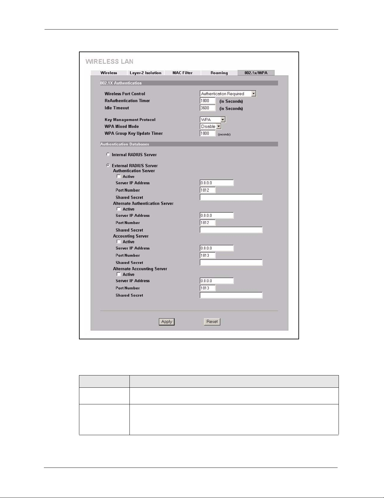
ZyAIR G-3000 User’s Guide
Figure 44 Wireless LAN: 802.1x/WPA for WPA Protocol
The following table describes the labels not previously discussed
Table 22 Wireless LAN: 802.1x/WPA for WPA Protocol
LABEL DESCRIPTIONS
Key Management
Protocol
WPA Mixed Mode The ZyAIR can operate in WPA Mixed Mode, which supports both clients running
97 Chapter 6 Wireless Security
Choose WPA in this field.
WPA and clients running dynamic WEP key exchange with 802.1x in the same WiFi network.
Select Enable to activate WPA mixed mode. Otherwise, select Disable.
Page 99

Table 22 Wireless LAN: 802.1x/WPA for WPA Protocol
LABEL DESCRIPTIONS
ZyAIR G-3000 User’s Guide
WPA Group Key
Update Timer
Authentication Databases
Internal RADIUS
Server
External RADIUS
Server
Apply Click Apply to save your changes back to the ZyAIR.
Reset Click Reset to begin configuring this screen afresh.
The WPA Group Key Update Timer is the rate at which the AP (if using WPA-
PSK key management) or RADIUS server (if using WPA key management) sends
a new group key out to all clients. The re-keying process is the WPA equivalent of
automatically changing the WEP key for an AP and all stations in a WLAN on a
periodic basis. Setting of the WPA Group Key Update Timer is also supported in
WPA-PSK mode. The ZyAIR default is 1800 seconds (30 minutes).
Select this radio button to use the ZyAIR’s Internal RADIUS Server. You can
authenticate other AP’s or wireless clients in other wireless networks.
Select the radio button to use an External RADIUS Server to authenticate the
ZyAIR’s wireless clients.
Please see Table 21 for information on the additional fields shown in this screen.
6.19 Authentication Required: WPA-PSK
Select Authentication Required in the Wireless Port Control field and WPA-PSK in the
Key Management Protocol field to display the next screen.
Chapter 6 Wireless Security 98
Page 100
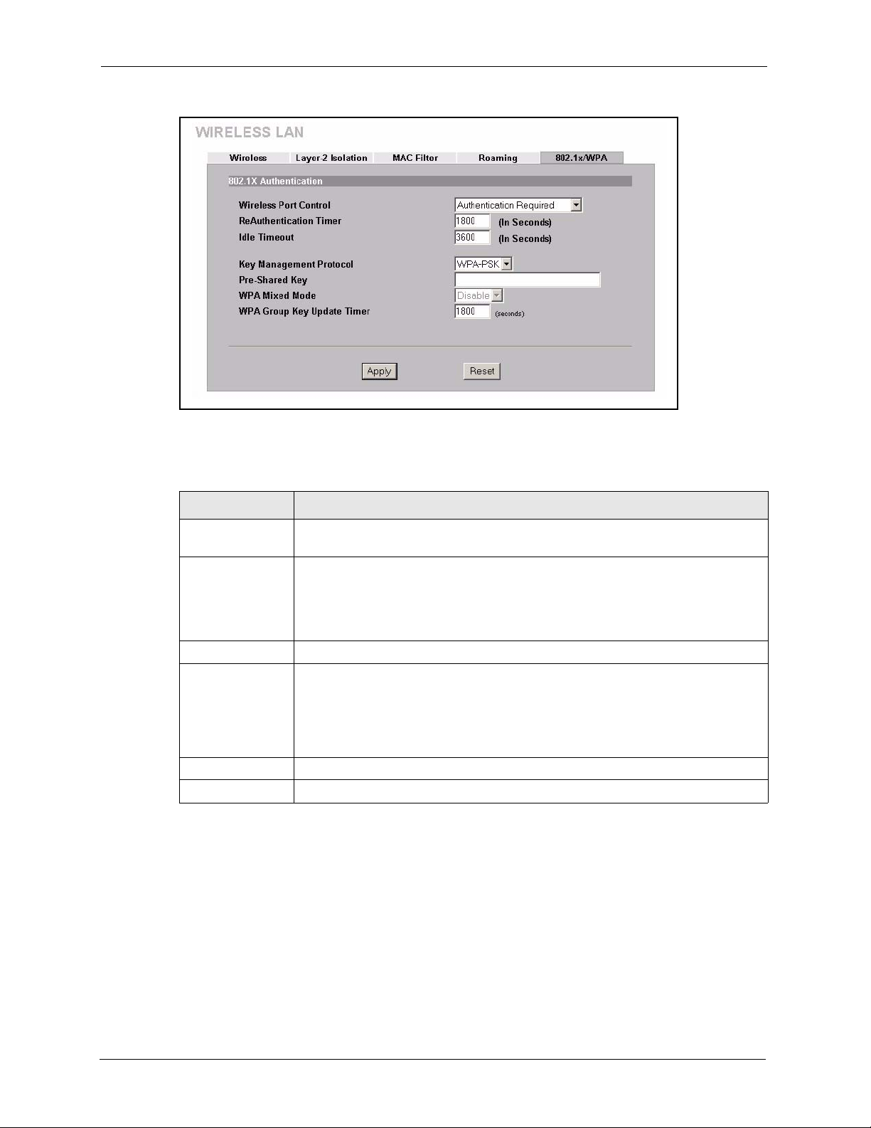
ZyAIR G-3000 User’s Guide
Figure 45 Wireless LAN: 802.1x/WPA for WPA-PSK Protocol
The following table describes the labels not previously discussed
Table 23 Wireless LAN: 802.1x/WPA for WPA-PSK Protocol
LABEL DESCRIPTION
Key Management
Protocol
Pre-Shared Key The encryption mechanisms used for WPA and WPA-PSK are the same. The only
WPA Mixed Mode This field is disabled for WPA-PSK key management protocol.
WPA Group Key
Update Timer
Apply Click Apply to save your changes back to the ZyAIR.
Reset Click Reset to begin configuring this screen afresh.
Choose WPA-PSK in this field.
difference between the two is that WPA-PSK uses a simple common password,
instead of user-specific credentials.
Type a pre-shared key from 8 to 63 case-sensitive ASCII characters (including
spaces and symbols).
The WPA Group Key Update Timer is the rate at which the AP (if using WPA-
PSK key management) or RADIUS server (if using WPA key management) sends
a new group key out to all clients. The re-keying process is the WPA equivalent of
automatically changing the WEP key for an AP and all stations in a WLAN on a
periodic basis. Setting of the WPA Group Key Update Timer is also supported in
WPA-PSK mode. The ZyAIR default is 1800 seconds (30 minutes).
99 Chapter 6 Wireless Security
 Loading...