

Page 1
Default Login Details
User’s Guide
XS3800-28
28-port 10GbE L2+ Managed Switch
Out-of-Band
MGMT Port
In-Band Ports http://DHCP-assigned IP
User Name admin
Password 1234
http://192.168.0.1
or
http://192.168.1.1
Version 4.60 Edition 2, 05/2019
Copyright © 2019 Zyxel Communications Corporation
Page 2

IMPORTANT!
READ CAREFULLY BEFORE USE.
KEEP THIS GUIDE FOR FUTURE REFERENCE.
Screenshots and graphics in this book may differ slightly from your product due to differences in your
product firmware or your computer operating system. Every effort has been made to ensure that the
information in this manual is accurate.
Related Documentation
•CLI Reference Guide
This guide explains how to use the Command-Line Interface (CLI) to configure the Switch.
Note: It is recommended you use the Web Configurator to configure the Switch.
• Web Configurator Online Help
Click the help icon in any screen for help in configuring that screen and supplementary information.
•More Information
Go to https://businessforum.zyxel.com for product discussions.
Go to support.zyxel.com to find other information on the Switch
.
XS3800-28 User’s Guide
2
Page 3

Contents Overview
Contents Overview
User’s Guide ......................................................................................................................................21
Getting to Know Your Switch .............................................................................................................. 22
Hardware Installation and Connection ............................................................................................. 32
Hardware Overview ............................................................................................................................. 35
The Web Configurator ......................................................................................................................... 43
Initial Setup Example ............................................................................................................................ 59
Tutorials .................................................................................................................................................. 63
Technical Reference ........................................................................................................................74
Status ...................................................................................................................................................... 75
Basic Setting ......................................................................................................................................... 79
VLAN .................................................................................................................................................... 119
Static MAC Forward Setup ................................................................................................................ 143
Static Multicast Forward Setup ......................................................................................................... 146
Filtering ................................................................................................................................................. 150
Spanning Tree Protocol ...................................................................................................................... 152
Bandwidth Control ............................................................................................................................. 178
Broadcast Storm Control ................................................................................................................... 181
Mirroring ............................................................................................................................................... 184
Link Aggregation ................................................................................................................................ 196
Port Authentication ............................................................................................................................ 206
Port Security ......................................................................................................................................... 220
Time Range ......................................................................................................................................... 225
Classifier ............................................................................................................................................... 227
Policy Rule .......................................................................................................................................... 236
Queuing Method ................................................................................................................................ 241
VLAN Stacking .................................................................................................................................... 245
Multicast .............................................................................................................................................. 254
AAA ...................................................................................................................................................... 280
IP Source Guard .................................................................................................................................. 292
Loop Guard ......................................................................................................................................... 327
VLAN Mapping ................................................................................................................................... 331
Layer 2 Protocol Tunneling ................................................................................................................ 335
sFlow ..................................................................................................................................................... 340
PPPoE ................................................................................................................................................... 344
Error Disable ......................................................................................................................................... 353
MAC Pinning ....................................................................................................................................... 361
Private VLAN ....................................................................................................................................... 364
XS3800-28 User’s Guide
3
Page 4

Contents Overview
Green Ethernet ................................................................................................................................... 368
Link Layer Discovery Protocol (LLDP) ................................................................................................ 371
Anti-Arpscan ....................................................................................................................................... 399
BPDU Guard ........................................................................................................................................ 405
OAM ..................................................................................................................................................... 409
ZULD ...................................................................................................................................................... 419
NLB ........................................................................................................................................................ 425
Wol Relay ............................................................................................................................................. 430
Static Route ......................................................................................................................................... 432
Policy Routing ..................................................................................................................................... 436
Differentiated Services ....................................................................................................................... 440
DHCP .................................................................................................................................................... 445
VRRP ..................................................................................................................................................... 463
Router Setup ........................................................................................................................................ 472
ARP Setup ............................................................................................................................................ 474
Maintenance ...................................................................................................................................... 480
Access Control .................................................................................................................................... 495
Diagnostic ........................................................................................................................................... 518
System Log .......................................................................................................................................... 522
Syslog Setup ........................................................................................................................................ 523
Cluster Management ......................................................................................................................... 526
MAC Table ........................................................................................................................................... 531
IP Table ................................................................................................................................................. 534
ARP Table ............................................................................................................................................ 536
Routing Table ...................................................................................................................................... 538
Path MTU Table ................................................................................................................................... 540
Configure Clone ................................................................................................................................. 541
IPv6 Neighbor Table ........................................................................................................................... 545
Port Status ............................................................................................................................................ 547
Troubleshooting and Appendices .................................................................................................557
Troubleshooting .................................................................................................................................. 558
XS3800-28 User’s Guide
4
Page 5

Table of Contents
Table of Contents
Contents Overview .............................................................................................................................3
Table of Contents.................................................................................................................................5
Part I: User’s Guide.......................................................................................... 21
Chapter 1
Getting to Know Your Switch ............................................................................................................22
1.1 Introduction ..................................................................................................................................... 22
1.1.1 Multi-Gigabit .......................................................................................................................... 23
1.1.2 Stacking Mode ...................................................................................................................... 24
1.1.3 Management Method ......................................................................................................... 25
1.1.4 Management Modes ........................................................................................................... 25
1.1.5 Mode Changing ................................................................................................................... 26
1.1.6 ZON Utility ............................................................................................................................... 27
1.2 Applications .................................................................................................................................... 28
1.2.1 Bridging Example .................................................................................................................. 28
1.2.2 High Performance Switching Example ............................................................................... 28
1.2.3 IEEE 802.1Q VLAN Application Example ............................................................................. 29
1.2.4 IPv6 Support ........................................................................................................................... 30
1.3 Ways to Manage the Switch ......................................................................................................... 30
1.4 Good Habits for Managing the Switch ........................................................................................31
Chapter 2
Hardware Installation and Connection ...........................................................................................32
2.1 Freestanding Installation ............................................................................................................... 32
2.2 Rack Mounting ............................................................................................................................... 33
2.2.1 Installation Requirements ..................................................................................................... 33
2.2.2 Attaching the Mounting Brackets to the Switch ............................................................... 33
2.2.3 Mounting the Switch on a Rack .......................................................................................... 34
Chapter 3
Hardware Overview...........................................................................................................................35
3.1 Front Panel Connections .............................................................................................................. 35
3.1.1 SFP/SFP+ Slots ........................................................................................................................ 36
3.1.2 Ethernet Ports ......................................................................................................................... 37
3.1.3 Dual Personality Interfaces .................................................................................................. 38
3.1.4 Management Port ................................................................................................................ 38
XS3800-28 User’s Guide
5
Page 6

Table of Contents
3.1.5 Console Port ......................................................................................................................... 38
3.2 Rear Panel ....................................................................................................................................... 39
3.2.1 Grounding .............................................................................................................................. 39
3.2.2 AC Power Connection ......................................................................................................... 40
3.3 LEDs .............................................................................................................................................. 40
Chapter 4
The Web Configurator........................................................................................................................43
4.1 Introduction ..................................................................................................................................... 43
4.2 System Login ............................................................................................................................... 43
4.3 Zyxel One Network (ZON) Utility ................................................................................................... 46
4.3.1 Requirements ......................................................................................................................... 46
4.3.2 Run the ZON Utility ................................................................................................................. 47
4.4 The Web Configurator Layout ..................................................................................................... 50
4.4.1 Change Your Password ..................................................................................................... 55
4.5 Saving Your Configuration ............................................................................................................. 56
4.6 Switch Lockout .............................................................................................................................. 56
4.7 Resetting the Switch .................................................................................................................... 57
4.7.1 Using the RESTORE Button ..................................................................................................... 57
4.7.2 Reload the Configuration File ............................................................................................. 57
4.8 Logging Out of the Web Configurator .......................................................................................58
4.9 Help ................................................................................................................................................. 58
Chapter 5
Initial Setup Example.........................................................................................................................59
5.1 Overview ......................................................................................................................................... 59
5.1.1 Creating a VLAN ................................................................................................................... 59
5.1.2 Setting Port VID ...................................................................................................................... 60
5.1.3 Configuring Switch Management IP Address .................................................................... 61
Chapter 6
Tutorials...............................................................................................................................................63
6.1 Overview ......................................................................................................................................... 63
6.2 How to Use DHCPv4 Snooping on the Switch ............................................................................. 63
6.3 How to Use DHCPv4 Relay on the Switch .................................................................................... 66
6.3.1 DHCP Relay Tutorial Introduction ........................................................................................ 67
6.3.2 Creating a VLAN ................................................................................................................... 67
6.3.3 Configuring DHCPv4 Relay .................................................................................................. 69
6.3.4 Troubleshooting ..................................................................................................................... 70
6.4 How to Use Auto Configuration via a DHCP Server on the Switch ........................................... 70
Part II: Technical Reference...........................................................................74
XS3800-28 User’s Guide
6
Page 7

Table of Contents
Chapter 7
Status...................................................................................................................................................75
7.1 Overview ......................................................................................................................................... 75
7.2 Status ................................................................................................................................................ 75
7.3 Neighbor Screen ............................................................................................................................ 77
Chapter 8
Basic Setting ......................................................................................................................................79
8.1 System Information ...................................................................................................................... 79
8.1.1 System Information Stacking Hardware Monitor .............................................................. 82
8.2 General Setup ............................................................................................................................... 84
8.3 Switch Setup ................................................................................................................................... 86
8.3.1 Introduction to VLANs .......................................................................................................... 86
8.4 IP Setup ......................................................................................................................................... 89
8.4.1 IP Interfaces .......................................................................................................................... 89
8.4.2 IP Status Details .................................................................................................................... 90
8.4.3 IP Configuration ................................................................................................................... 91
8.5 Port Setup ....................................................................................................................................... 94
8.6 Interface Setup ............................................................................................................................... 97
8.7 IPv6 ................................................................................................................................................... 98
8.7.1 IPv6 Interface Status ............................................................................................................. 98
8.7.2 IPv6 Configuration .............................................................................................................. 100
8.7.3 IPv6 Global Setup ................................................................................................................ 101
8.7.4 IPv6 Interface Setup ............................................................................................................ 102
8.7.5 IPv6 Link-Local Address Setup ............................................................................................103
8.7.6 IPv6 Global Address Setup ................................................................................................. 103
8.7.7 IPv6 Neighbor Discovery Setup ......................................................................................... 104
8.7.8 IPv6 Router Discovery Setup ..............................................................................................105
8.7.9 IPv6 Prefix Setup .................................................................................................................. 107
8.7.10 IPv6 Neighbor Setup ......................................................................................................... 108
8.7.11 DHCPv6 Client Setup ........................................................................................................ 109
8.8 Stacking ......................................................................................................................................... 111
8.8.1 Stacking Status .................................................................................................................... 112
8.8.2 Stacking Slot ....................................................................................................................... 113
8.8.3 Stacking Configuration ...................................................................................................... 114
8.9 DNS ................................................................................................................................................. 116
8.10 Cloud Management .................................................................................................................. 117
8.10.1 Nebula Center Control Discovery ................................................................................... 117
8.10.2 Nebula Switch Registration ..............................................................................................118
Chapter 9
VLAN..................................................................................................................................................119
9.1 Introduction to IEEE 802.1Q Tagged VLANs ............................................................................ 119
XS3800-28 User’s Guide
7
Page 8

Table of Contents
9.1.1 Forwarding Tagged and Untagged Frames .................................................................... 119
9.2 Automatic VLAN Registration .................................................................................................... 120
9.2.1 GARP .................................................................................................................................... 120
9.2.2 GVRP .................................................................................................................................... 120
9.3 Port VLAN Trunking ...................................................................................................................... 121
9.4 Select the VLAN Type .................................................................................................................. 121
9.5 802.1Q Static VLAN ....................................................................................................................... 121
9.5.1 VLAN Status ......................................................................................................................... 122
9.5.2 VLAN Details ........................................................................................................................ 123
9.6 Private VLAN Status ..................................................................................................................... 124
9.7 VLAN Configuration .................................................................................................................... 125
9.7.1 Configure a Static VLAN ............................................................................................... 125
9.7.2 Configure VLAN Port Settings ........................................................................................ 128
9.7.3 Subnet Based VLANs .......................................................................................................... 130
9.7.4 Protocol Based VLANs ....................................................................................................... 133
9.8 Voice VLAN .................................................................................................................................. 136
9.9 MAC Based VLAN ......................................................................................................................... 138
9.10 Port-based VLAN Setup ......................................................................................................... 139
9.10.1 Configure a Port-based VLAN ........................................................................................ 139
Chapter 10
Static MAC Forward Setup ..............................................................................................................143
10.1 Overview ..................................................................................................................................... 143
10.2 Configuring Static MAC Forwarding ................................................................................... 143
Chapter 11
Static Multicast Forward Setup .......................................................................................................146
11.1 Static Multicast Forwarding Overview ..................................................................................... 146
11.2 Configuring Static Multicast Forwarding .................................................................................. 147
Chapter 12
Filtering..............................................................................................................................................150
12.1 Configure a Filtering Rule ........................................................................................................ 150
Chapter 13
Spanning Tree Protocol ...................................................................................................................152
13.1 Spanning Tree Protocol Overview ........................................................................................... 152
13.1.1 What You Need to Know ................................................................................................. 152
13.2 Spanning Tree Protocol Status Screen ..................................................................................... 154
13.3 Spanning Tree Configuration ................................................................................................... 155
13.4 Configure Rapid Spanning Tree Protocol ............................................................................. 156
13.5 Rapid Spanning Tree Protocol Status ....................................................................................158
13.6 Configure Multiple Rapid Spanning Tree Protocol .............................................................. 160
XS3800-28 User’s Guide
8
Page 9

Table of Contents
13.7 Multiple Rapid Spanning Tree Protocol Status .................................................................... 163
13.8 Configure Multiple Spanning Tree Protocol .......................................................................... 165
13.8.1 Multiple Spanning Tree Protocol Port Configuration .................................................... 169
13.9 Multiple Spanning Tree Protocol Status .................................................................................171
13.10 Technical Reference ................................................................................................................ 175
13.10.1 MSTP Network Example .................................................................................................. 175
13.10.2 MST Region ....................................................................................................................... 176
13.10.3 MST Instance .................................................................................................................... 176
13.10.4 Common and Internal Spanning Tree (CIST) ............................................................... 177
Chapter 14
Bandwidth Control...........................................................................................................................178
14.1 Bandwidth Control Overview .................................................................................................. 178
14.1.1 CIR and PIR ........................................................................................................................ 178
14.2 Bandwidth Control Setup .......................................................................................................... 178
Chapter 15
Broadcast Storm Control .................................................................................................................181
15.1 Broadcast Storm Control Setup ............................................................................................... 181
Chapter 16
Mirroring............................................................................................................................................184
16.1 Port Mirroring .............................................................................................................................. 184
16.1.1 Local Port Mirroring ........................................................................................................... 186
16.1.2 Remote Port Mirroring ....................................................................................................... 188
16.1.3 Source ................................................................................................................................ 189
16.1.4 Destination ......................................................................................................................... 192
16.1.5 Connected Port ................................................................................................................ 193
Chapter 17
Link Aggregation .................................... .... .... ... ..............................................................................196
17.1 Link Aggregation Overview ...................................................................................................... 196
17.2 Dynamic Link Aggregation ...................................................................................................... 196
17.2.1 Link Aggregation ID ......................................................................................................... 197
17.3 Link Aggregation Status ............................................................................................................. 197
17.4 Link Aggregation Setting .......................................................................................................... 198
17.5 Link Aggregation Control Protocol ........................................................................................ 201
17.6 Static Trunking Example ............................................................................................................. 204
Chapter 18
Port Authentication..........................................................................................................................206
18.1 Port Authentication Overview ................................................................................................. 206
18.1.1 IEEE 802.1x Authentication ............................................................................................... 206
XS3800-28 User’s Guide
9
Page 10

Table of Contents
18.1.2 MAC Authentication ........................................................................................................ 207
18.2 Port Authentication Configuration ........................................................................................... 208
18.2.1 Activate IEEE 802.1x Security ........................................................................................ 208
18.2.2 Guest VLAN ....................................................................................................................... 211
18.2.3 Activate MAC Authentication ....................................................................................... 213
18.3 Technical Reference .................................................................................................................. 216
18.3.1 IEEE 802.1x .......................................................................................................................... 216
18.3.2 RADIUS ................................................................................................................................ 217
18.3.3 EAP (Extensible Authentication Protocol) Authentication ........................................... 218
18.3.4 EAPOL (EAP over LAN) ...................................................................................................... 219
Chapter 19
Port Security......................................................................................................................................220
19.1 About Port Security ..................................................................................................................... 220
19.2 Port Security Setup ...................................................................................................................... 220
19.3 VLAN MAC Address Limit .......................................................................................................... 222
Chapter 20
Time Range.......................................................................................................................................225
20.1 About Time Range ..................................................................................................................... 225
20.2 Time Range Setup ...................................................................................................................... 225
Chapter 21
Classifier............................................................................................................................................227
21.1 About the Classifier and QoS .................................................................................................... 227
21.2 Classifier Status ............................................................................................................................ 227
21.3 Classifier Configuration .............................................................................................................. 228
21.3.1 Viewing and Editing Classifier Configuration ................................................................. 232
21.4 Classifier Global Setting Configuration .................................................................................... 233
21.5 Classifier Example ....................................................................................................................... 234
Chapter 22
Policy Rule .......................................................................................................................................236
22.1 Policy Rules Overview ............................................................................................................... 236
22.1.1 DiffServ ................................................................................................................................ 236
22.1.2 DSCP and Per-Hop Behavior ........................................................................................... 236
22.2 Configuring Policy Rules ............................................................................................................ 236
22.3 Policy Example ............................................................................................................................ 239
Chapter 23
Queuing Method..............................................................................................................................241
23.1 Queuing Method Overview ..................................................................................................... 241
23.1.1 Strictly Priority ..................................................................................................................... 241
XS3800-28 User’s Guide
10
Page 11

Table of Contents
23.1.2 Weighted Fair Queuing .................................................................................................... 241
23.1.3 Weighted Round Robin Scheduling (WRR) .................................................................... 241
23.2 Configuring Queuing ................................................................................................................. 242
Chapter 24
VLAN Stacking..................................................................................................................................245
24.1 VLAN Stacking Overview .......................................................................................................... 245
24.1.1 VLAN Stacking Example ...................................................................................................245
24.2 VLAN Stacking Port Roles ........................................................................................................... 246
24.3 VLAN Tag Format ........................................................................................................................ 246
24.3.1 Frame Format .................................................................................................................... 247
24.4 Configuring VLAN Stacking ....................................................................................................... 247
24.4.1 Port-based Q-in-Q ............................................................................................................. 249
24.4.2 Selective Q-in-Q ............................................................................................................... 251
Chapter 25
Multicast............................................................................................................................................254
25.1 Multicast Overview .................................................................................................................... 254
25.1.1 IP Multicast Addresses ...................................................................................................... 254
25.1.2 IGMP Filtering ..................................................................................................................... 254
25.1.3 IGMP Snooping ................................................................................................................. 255
25.1.4 IGMP Snooping and VLANs ............................................................................................. 255
25.1.5 MLD Snooping-Proxy ......................................................................................................... 255
25.1.6 MLD Messages ................................................................................................................... 256
25.2 Multicast Setup ........................................................................................................................... 256
25.3 IPv4 Multicast Status .................................................................................................................. 257
25.3.1 IGMP Snooping ................................................................................................................. 257
25.3.2 IGMP Snooping VLAN ...................................................................................................... 261
25.3.3 IGMP Filtering Profile ........................................................................................................ 262
25.4 IPv6 Multicast Status .................................................................................................................. 263
25.4.1 MLD Snooping-proxy ....................................................................................................... 264
25.4.2 MLD Snooping-proxy VLAN ............................................................................................. 264
25.4.3 MLD Snooping-proxy VLAN Port Role Setting ................................................................ 266
25.4.4 MLD Snooping-proxy Filtering ......................................................................................... 268
25.4.5 MLD Snooping-proxy Filtering Profile .............................................................................. 270
25.5 MVR Overview ........................................................................................................................... 271
25.5.1 Types of MVR Ports ............................................................................................................ 272
25.5.2 MVR Modes ........................................................................................................................ 272
25.5.3 How MVR Works ................................................................................................................ 272
25.6 General MVR Configuration ...................................................................................................... 273
25.6.1 MVR Group Configuration .............................................................................................. 276
25.6.2 MVR Configuration Example ........................................................................................... 278
XS3800-28 User’s Guide
11
Page 12

Table of Contents
Chapter 26
AAA...................................................................................................................................................280
26.1 Authentication, Authorization and Accounting (AAA) ......................................................... 280
26.1.1 Local User Accounts ......................................................................................................... 280
26.1.2 RADIUS and TACACS+ .....................................................................................................280
26.2 AAA Screens ............................................................................................................................... 281
26.2.1 RADIUS Server Setup ....................................................................................................... 281
26.2.2 TACACS+ Server Setup ................................................................................................. 283
26.2.3 AAA Setup ......................................................................................................................... 284
26.2.4 Vendor Specific Attribute ................................................................................................ 287
26.2.5 Tunnel Protocol Attribute .................................................................................................. 288
26.3 Supported RADIUS Attributes .................................................................................................... 288
26.3.1 Attributes Used for Authentication .................................................................................. 289
26.3.2 Attributes Used for Accounting ....................................................................................... 289
Chapter 27
IP Source Guard................................................................................................................ ...............292
27.1 IP Source Guard Overview ........................................................................................................ 292
27.1.1 What You Can Do ............................................................................................................. 292
27.1.2 What You Need to Know ................................................................................................ 293
27.2 IP Source Guard .......................................................................................................................... 294
27.3 IPv4 Source Guard Setup .......................................................................................................... 295
27.4 IPv4 Source Guard Static Binding ............................................................................................. 295
27.5 DHCP Snooping .......................................................................................................................... 298
27.6 DHCP Snooping Configure ........................................................................................................ 300
27.6.1 DHCP Snooping Port Configure ...................................................................................... 302
27.6.2 DHCP Snooping VLAN Configure .................................................................................... 304
27.6.3 DHCP Snooping VLAN Port Configure ............................................................................ 305
27.7 ARP Inspection Status ................................................................................................................. 306
27.7.1 ARP Inspection VLAN Status ............................................................................................. 307
27.7.2 ARP Inspection Log Status ................................................................................................ 308
27.8 ARP Inspection Configure .......................................................................................................... 309
27.8.1 ARP Inspection Port Configure ........................................................................................ 310
27.8.2 ARP Inspection VLAN Configure ..................................................................................... 312
27.9 IPv6 Source Guard Overview ................................................................................................... 313
27.10 IPv6 Source Binding Status ....................................................................................................... 314
27.11 IPv6 Static Binding Setup ........................................................................................................ 315
27.12 IPv6 Source Guard Policy Setup ............................................................................................ 316
27.13 IPv6 Source Guard Port Setup ................................................................................................ 317
27.14 IPv6 Snooping Policy Setup .................................................................................................... 319
27.15 IPv6 Snooping VLAN Setup ..................................................................................................... 320
27.16 IPv6 DHCP Trust Setup ............................................................................................................. 321
27.17 Technical Reference ................................................................................................................ 323
XS3800-28 User’s Guide
12
Page 13

Table of Contents
27.17.1 DHCP Snooping Overview ............................................................................................. 323
27.17.2 ARP Inspection Overview ............................................................................................... 325
Chapter 28
Loop Guard ..................................................................................................................... .................327
28.1 Loop Guard Overview .............................................................................................................. 327
28.2 Loop Guard Setup ...................................................................................................................... 328
Chapter 29
VLAN Mapping.................................................................................................................................331
29.1 VLAN Mapping Overview ......................................................................................................... 331
29.1.1 VLAN Mapping Example .................................................................................................. 331
29.2 Enabling VLAN Mapping ........................................................................................................... 331
29.3 Configuring VLAN Mapping ...................................................................................................... 333
Chapter 30
Layer 2 Protocol Tunneling..............................................................................................................335
30.1 Layer 2 Protocol Tunneling Overview ......................................................................................335
30.1.1 Layer-2 Protocol Tunneling Mode ................................................................................... 336
30.2 Configuring Layer 2 Protocol Tunneling ................................................................................... 336
Chapter 31
sFlow..................................................................................................................................................340
31.1 sFlow Overview ........................................................................................................................... 340
31.2 sFlow Port Configuration ............................................................................................................ 340
31.2.1 sFlow Collector Configuration ......................................................................................... 342
Chapter 32
PPPoE.................................................................................................................................................344
32.1 PPPoE Intermediate Agent Overview ..................................................................................... 344
32.1.1 PPPoE Intermediate Agent Tag Format .......................................................................... 344
32.1.2 Sub-Option Format ........................................................................................................... 344
32.1.3 Port State ............................................................................................................................ 345
32.2 The PPPoE Screen ....................................................................................................................... 346
32.3 PPPoE Intermediate Agent ....................................................................................................... 346
32.3.1 PPPoE IA Per-Port .............................................................................................................. 348
32.3.2 PPPoE IA Per-Port Per-VLAN ............................................................................................ 350
32.3.3 PPPoE IA for VLAN ............................................................................................................ 351
Chapter 33
Error Disable......................................................................................................................................353
33.1 Error Disable Overview .............................................................................................................. 353
33.1.1 CPU Protection Overview ................................................................................................ 353
XS3800-28 User’s Guide
13
Page 14

Table of Contents
33.1.2 Error-Disable Recovery Overview .................................................................................... 353
33.1.3 What You Can Do ............................................................................................................. 353
33.2 The Error Disable Screen ............................................................................................................ 354
33.3 Error-Disable Status .................................................................................................................... 354
33.4 CPU Protection Configuration .................................................................................................. 356
33.5 Error-Disable Detect Configuration ......................................................................................... 358
33.6 Error-Disable Recovery Configuration .....................................................................................359
Chapter 34
MAC Pinning.....................................................................................................................................361
34.1 MAC Pinning Overview ............................................................................................................. 361
34.2 MAC Pinning Configuration ...................................................................................................... 361
Chapter 35
Private VLAN............................................ .........................................................................................364
35.1 Private VLAN Overview ............................................................................................................. 364
35.1.1 Configuration .................................................................................................................... 365
Chapter 36
Green Ethernet................................................ ... .... ..........................................................................368
36.1 Green Ethernet Overview ......................................................................................................... 368
36.2 Configuring Green Ethernet ...................................................................................................... 368
Chapter 37
Link Layer Discovery Protocol (LLDP) .............................................................................................371
37.1 LLDP Overview ............................................................................................................................ 371
37.2 LLDP-MED Overview ................................................................................................................... 372
37.3 LLDP Screens ............................................................................................................................... 373
37.4 LLDP Local Status ....................................................................................................................... 374
37.4.1 LLDP Local Port Status Detail ..........................................................................................376
37.5 LLDP Remote Status ................................................................................................................... 379
37.5.1 LLDP Remote Port Status Detail ...................................................................................... 380
37.6 LLDP Configuration .................................................................................................................... 386
37.6.1 LLDP Configuration Basic TLV Setting ............................................................................. 388
37.6.2 LLDP Configuration Basic Org-specific TLV Setting ...................................................... 390
37.7 LLDP-MED Configuration ........................................................................................................... 391
37.8 LLDP-MED Network Policy ........................................................................................................ 393
37.9 LLDP-MED Location .................................................................................................................. 394
Chapter 38
Anti-Arpscan ....................................................................................................................................399
38.1 Anti-Arpscan Overview ............................................................................................................. 399
38.1.1 What You Can Do ............................................................................................................. 399
XS3800-28 User’s Guide
14
Page 15

Table of Contents
38.1.2 What You Need to Know ................................................................................................. 399
38.2 Anti-Arpscan Status ................................................................................................................... 400
38.3 Anti-Arpscan Host Status ........................................................................................................... 401
38.4 Anti-Arpscan Trust Host ............................................................................................................. 402
38.5 Anti-Arpscan Configure ............................................................................................................ 402
Chapter 39
BPDU Guard......................................................................................................................................405
39.1 BPDU Guard Overview .............................................................................................................. 405
39.1.1 What You Can Do ............................................................................................................. 405
39.2 BPDU Guard Status ..................................................................................................................... 405
39.3 BPDU Guard Configuration ....................................................................................................... 407
Chapter 40
OAM..................................................................................................................................................409
40.1 OAM Overview .......................................................................................................................... 409
40.1.1 What You Can Do ............................................................................................................. 409
40.2 OAM Status .................................................................................................................................. 409
40.2.1 OAM Details ....................................................................................................................... 411
40.3 OAM Configuration .................................................................................................................... 415
40.4 OAM Remote Loopback ........................................................................................................... 417
Chapter 41
ZULD...................................................................................................................................................419
41.1 ZULD Overview ........................................................................................................................... 419
41.1.1 What You Can Do ............................................................................................................. 419
41.1.2 What You Need to Know ................................................................................................. 419
41.2 ZULD Status .................................................................................................................................. 420
41.3 ZULD Configuration ................................................................................................................... 422
Chapter 42
NLB.....................................................................................................................................................425
42.1 NLB Overview .............................................................................................................................. 425
42.1.1 What You Can Do ............................................................................................................. 425
42.1.2 What You Need to Know ................................................................................................. 425
42.2 MAC Forwarding ........................................................................................................................ 426
42.3 IP Configuration .......................................................................................................................... 428
Chapter 43
Wol Relay..........................................................................................................................................430
43.1 Wol Relay Overview ................................................................................................................... 430
43.2 Wol Relay ..................................................................................................................................... 430
XS3800-28 User’s Guide
15
Page 16

Table of Contents
Chapter 44
Static Route.......................................................................................................................................432
44.1 Static Routing Overview ........................................................................................................... 432
44.2 Static Routing .............................................................................................................................. 432
44.3 Configuring IPv4 Static Route .................................................................................................. 433
44.4 Configuring IPv6 Static Route .................................................................................................. 434
Chapter 45
Policy Routing...................................................................................................................................436
45.1 Policy Route Overview .............................................................................................................. 436
45.1.1 Benefits ............................................................................................................................... 436
45.2 Configuring Policy Routing Profile ............................................................................................. 436
45.2.1 Policy Routing Rule Configuration ................................................................................. 437
Chapter 46
Differentiated Services ....................................................................................................................440
46.1 DiffServ Overview ...................................................................................................................... 440
46.1.1 DSCP and Per-Hop Behavior ........................................................................................... 440
46.1.2 DiffServ Network Example ...............................................................................................440
46.2 Activating DiffServ ..................................................................................................................... 441
46.3 DSCP-to-IEEE 802.1p Priority Settings ......................................................................................... 443
46.3.1 Configuring DSCP Settings ...............................................................................................443
Chapter 47
DHCP .................................................................................................................................................445
47.1 DHCP Overview ......................................................................................................................... 445
47.1.1 DHCP Modes .................................................................................................................... 445
47.1.2 DHCP Configuration Options ........................................................................................... 445
47.2 DHCP Configuration ................................................................................................................... 445
47.3 DHCPv4 Status ........................................................................................................................... 446
47.3.1 DHCPv4 Server Status Detail ........................................................................................... 447
47.4 DHCPv4 Relay ............................................................................................................................ 447
47.4.1 DHCPv4 Relay Agent Information ................................................................................... 448
47.4.2 DHCPv4 Option 82 Profile ................................................................................................. 449
47.4.3 Configure DHCPv4 Global Relay .................................................................................... 450
47.4.4 DHCPv4 Global Relay Port Configure ........................................................................... 451
47.4.5 Global DHCP Relay Configuration Example .................................................................. 452
47.5 Configure DHCPv4 VLAN Settings .........................................................................................452
47.5.1 DHCPv4 VLAN Port Configure ........................................................................................ 454
47.5.2 Example: DHCP Relay for Two VLANs ............................................................................. 456
47.6 DHCPv6 Status ........................................................................................................................... 457
47.7 DHCPv6 Information ................................................................................................................... 457
47.8 DHCPv6 Prefix Delegation ......................................................................................................... 459
XS3800-28 User’s Guide
16
Page 17

Table of Contents
47.9 DHCPv6 Relay ............................................................................................................................. 460
Chapter 48
VRRP ..................................................................................................................................................463
48.1 VRRP Overview .......................................................................................................................... 463
48.2 VRRP Status .................................................................................................................................. 464
48.3 VRRP Configuration ................................................................................................................... 464
48.3.1 IP Interface Setup ............................................................................................................. 464
48.3.2 VRRP Parameters ............................................................................................................. 466
48.3.3 Configuring VRRP Parameters ......................................................................................... 466
48.3.4 Viewing VRRP Summary ................................................................................................... 467
48.4 VRRP Configuration Examples ................................................................................................. 468
48.4.1 One Subnet Network Example ....................................................................................... 468
48.4.2 Two Subnets Example ....................................................................................................... 469
Chapter 49
Router Setup .....................................................................................................................................472
49.1 Router Setup Overview ............................................................................................................. 472
49.2 Configuring Router Setup .......................................................................................................... 472
Chapter 50
ARP Setup..........................................................................................................................................474
50.1 ARP Overview ............................................................................................................................ 474
50.1.1 How ARP Works .................................................................................................................. 474
50.1.2 ARP Learning Mode .......................................................................................................... 474
50.2 ARP Setup .................................................................................................................................... 476
50.2.1 ARP Learning .................................................................................................................... 476
50.2.2 Static ARP ........................................................................................................................... 478
Chapter 51
Maintenance....................................................................................................................................480
51.1 The Maintenance Screen .......................................................................................................... 480
51.2 Erase Running-Configuration ................................................................................................... 481
51.3 Save Configuration .................................................................................................................... 482
51.4 Reboot System ............................................................................................................................ 482
51.4.1 Stacking Default ............................................................................................................... 483
51.4.2 Factory Default ................................................................................................................. 483
51.4.3 Custom Default ................................................................................................................ 484
51.5 Firmware Upgrade ...................................................................................................................... 484
51.6 Restore Configuration ................................................................................................................ 486
51.7 Backup Configuration ................................................................................................................ 487
51.8 Auto Configuration ................................................................................................................... 488
51.9 Tech-Support .............................................................................................................................. 489
XS3800-28 User’s Guide
17
Page 18

Table of Contents
51.10 Certificates ................................................................................................................................ 490
51.10.1 HTTPS Certificates ............................................................................................................ 491
51.11 FTP Command Line .................................................................................................................. 492
51.11.1 Filename Conventions ................................................................................................... 492
51.11.2 FTP Command Line Procedure ..................................................................................... 493
51.11.3 GUI-based FTP Clients ..................................................................................................... 494
51.11.4 FTP Restrictions ................................................................................................................ 494
Chapter 52
Access Control.................................................................................................................................495
52.1 Access Control Overview ...................................................................................................... 495
52.1.1 What You Can Do ............................................................................................................. 495
52.2 The Access Control Main Screen .............................................................................................. 495
52.3 About SNMP .............................................................................................................................. 496
52.3.1 SNMP v3 and Security ....................................................................................................... 497
52.3.2 Supported MIBs ............................................................................................................... 497
52.3.3 SNMP Traps ........................................................................................................................ 497
52.3.4 Configuring SNMP .......................................................................................................... 501
52.3.5 Configuring SNMP Trap Group ..................................................................................... 503
52.3.6 Enabling/Disabling Sending of SNMP Traps on a Port ................................................. 503
52.3.7 Configuring SNMP User .................................................................................................. 505
52.4 Set Up Login Accounts ............................................................................................................. 507
52.5 SSH Overview .............................................................................................................................. 508
52.6 How SSH works ............................................................................................................................ 508
52.7 SSH Implementation on the Switch ..........................................................................................509
52.7.1 Requirements for Using SSH ..............................................................................................510
52.8 Introduction to HTTPS .................................................................................................................. 510
52.9 HTTPS Example ............................................................................................................................ 511
52.9.1 Internet Explorer Warning Messages ............................................................................... 511
52.9.2 Mozilla Firefox Warning Messages ................................................................................... 512
52.9.3 Google Chrome Warning Messages .............................................................................. 514
52.9.4 The Main Screen ................................................................................................................ 514
52.10 Service Access Control ......................................................................................................... 515
52.11 Remote Management .......................................................................................................... 516
Chapter 53
Diagnostic.........................................................................................................................................518
53.1 Diagnostic .................................................................................................................................. 518
Chapter 54
System Log........................................................................................................................................522
54.1 Overview ..................................................................................................................................... 522
54.2 System Log .................................................................................................................................. 522
XS3800-28 User’s Guide
18
Page 19

Table of Contents
Chapter 55
Syslog Setup .....................................................................................................................................523
55.1 Syslog Overview .......................................................................................................................... 523
55.2 Syslog Setup ............................................................................................................................... 523
Chapter 56
Cluster Management.......................................................................................................................526
56.1 Cluster Management Status Overview ................................................................................... 526
56.2 Cluster Management Status .................................................................................................... 527
56.2.1 Cluster Member Switch Management .......................................................................... 527
56.3 Clustering Management Configuration ................................................................................ 529
Chapter 57
MAC Table........................................................................................................................................531
57.1 MAC Table Overview ................................................................................................................ 531
57.2 Viewing the MAC Table ............................................................................................................. 532
Chapter 58
IP Table..............................................................................................................................................534
58.1 IP Table Overview ...................................................................................................................... 534
58.2 Viewing the IP Table ................................................................................................................... 535
Chapter 59
ARP Table..........................................................................................................................................536
59.1 ARP Table Overview .................................................................................................................. 536
59.1.1 How ARP Works .................................................................................................................. 536
59.2 The ARP Table Screen ............................................................................................................... 536
Chapter 60
Routing Table....................................................................................................................................538
60.1 Routing Table Overview ........................................................................................................... 538
60.2 The Routing Table Main Screen ................................................................................................ 538
60.3 IPv4 Routing Table ...................................................................................................................... 538
60.4 IPv6 Routing Table ..................................................................................................................... 539
Chapter 61
Path MTU Table.................................................................................................................................540
61.1 Path MTU Overview ................................................................................................................... 540
61.2 Viewing the Path MTU Table ..................................................................................................... 540
Chapter 62
Configure Clone.................... .... ... .............................................................................. ......................541
62.1 Configure Clone ........................................................................................................................ 541
XS3800-28 User’s Guide
19
Page 20

Table of Contents
Chapter 63
IPv6 Neighbor Table.........................................................................................................................545
63.1 IPv6 Neighbor Table Overview ................................................................................................. 545
63.2 Viewing the IPv6 Neighbor Table ............................................................................................. 545
Chapter 64
Port Status .........................................................................................................................................547
64.1 Overview ..................................................................................................................................... 547
64.2 Status ............................................................................................................................................ 547
64.3 Port Status ................................................................................................................................... 547
64.3.1 Port Details ...................................................................................................................... 549
64.3.2 DDMI ................................................................................................................................... 552
64.3.3 DDMI Details ...................................................................................................................... 553
64.3.4 Port Utilization ................................................................................................................. 555
Part III: Troubleshooting and Appendices..................................................557
Chapter 65
Troubleshooting................................................................................................................................558
65.1 Power, Hardware Connections, and LEDs ............................................................................... 558
65.2 Switch Access and Login ........................................................................................................... 559
65.3 Switch Configuration .................................................................................................................. 560
Appendix A Customer Support ..................................................................................................... 562
Appendix B Common Services...................................................................................................... 568
Appendix C IPv6.............................................................................................................................. 571
Appendix D Legal Information ...................................................................................................... 579
Index.................................................................................................................................................584
XS3800-28 User’s Guide
20
Page 21

PART I
User’s Guide
21
Page 22

CHAPTER 1
Getting to Know Your Switch
This chapter introduces the main features and applications of the Switch.
1.1 Introduction
Your Switch is a stackable, layer-2, 10 Gigabit Ethernet (GbE) switch supporting Multi-Gigabit. See
Section 1.1.1 on page 23 for more information about Multi-Gigabit. The Switch equips with dual AC
power supply modules, and it’s ideal for SMB (Small-and-Medium-Sized Businesses) and enterprises.
You could use 10 Gigabit SFP+ slots for fiber connections to the backbone switches, and you could use
the 10 Gbps Ethernet ports for connections to other Ethernet devices requiring high-bandwidth, such as
network-attached storage (NAS), game consoles, servers, and so on.
The last four combo ports can also be used for stacking. When working in stacking mode, the Switch can
operate together with other Switches of the same model and firmware version and allows you to
remotely manage them from one switch using one single IP address.
The Switch performs full layer-2 switching features and basic layer-3 basic routing features, such as static
route (see Chapter 44 on page 432), and IGMP (see Chapter 25 on page 254).
XS3800-28 User’s Guide
22
Page 23
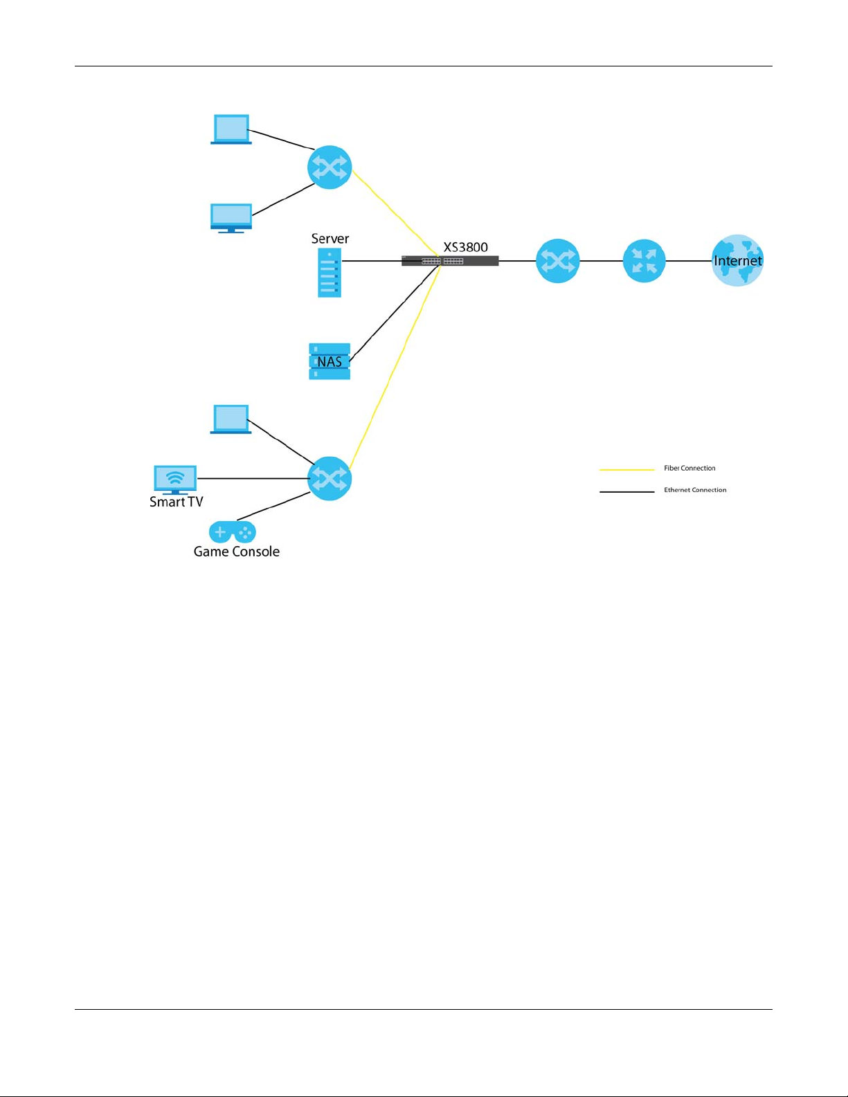
Chapter 1 Getting to Know Your Switch
Figure 1 Switch Application
1.1.1 Multi-Gigabit
A 10 Gigabit port supports speeds of 10 Gbps if the connected device supports 10 Gbps and a Cat 6a
(up to 100 m) or Cat 6 cable (up to 50 m) is used. The speed drops to 1G if these criteria are not met; it
drops to 100 Mbps if a Cat 5 cable is used (up to 100 m).
If a network device such as a 5G network card, gaming computer, server, Network Attached Storage
(NAS) or Access Point (AP) only supports 2.5 Gigabit or 5 Gigabit connectivity, then the maximum speed
potential of these devices is never reached.
In addition, at the time of writing, most existing cabling is Cat 5e or Cat 6, further limiting maximum
speed/distance potential.
Multi-Gigabit (IEEE 802.3bz) solves these problems by additionally supporting 2.5 Gigabit and 5 Gigabit
Ethernet connections over Cat 5e and higher Ethernet cables. Multi-Gigabit ports are also backward
compatible with 100 Mbps and 1 Gigabit ports.
XS3800-28 User’s Guide
23
Page 24
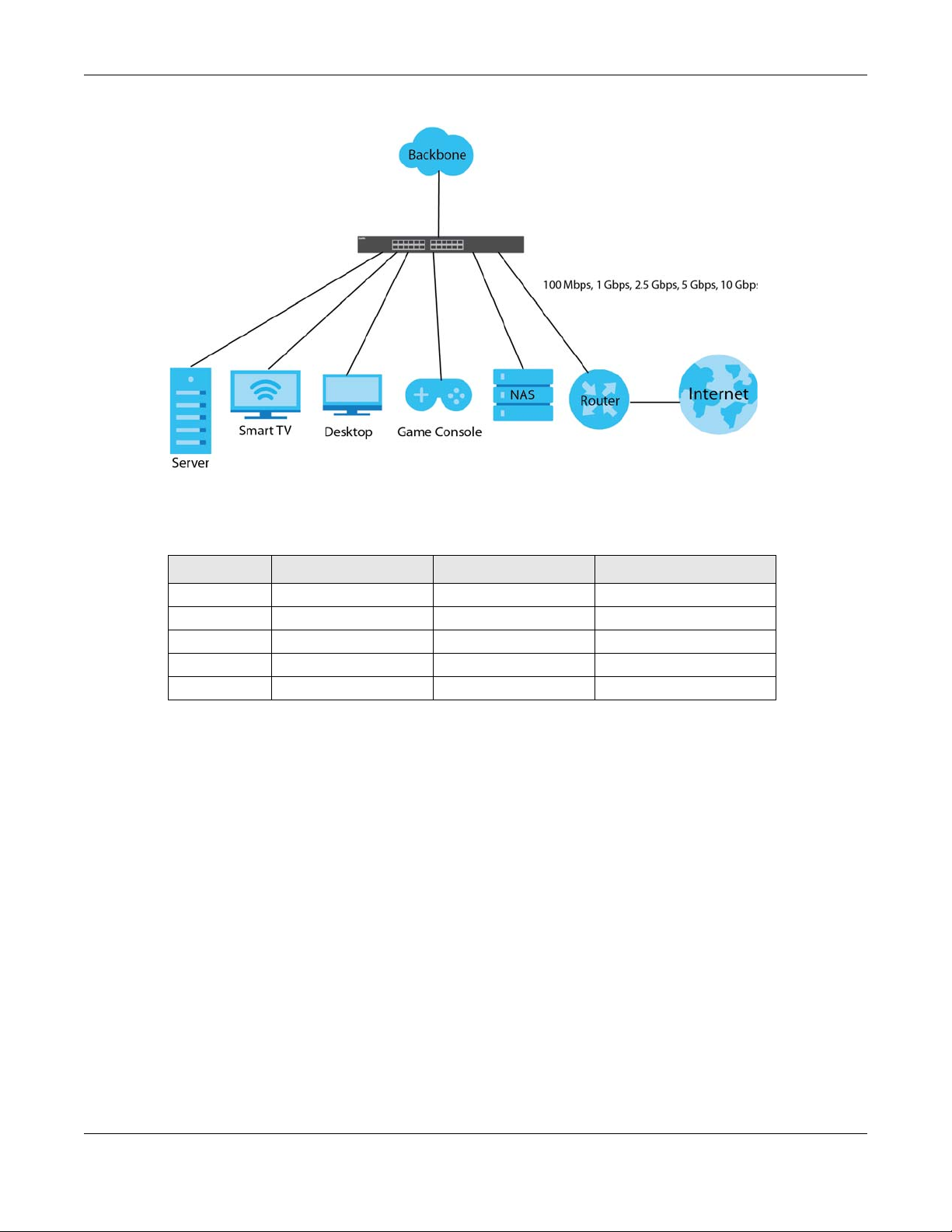
Chapter 1 Getting to Know Your Switch
Figure 2 Multi-Gigabit Application
See the following table for the cables required and distance limitation to attain the corresponding
speed.
Table 1 Cable Types
CABLE TRANSMISSION SPEED MAXIMUM DISTANCE BANDWIDTH CAPACITY
Category 5 100 Mbps 100 m 100 MHz
Category 5e 1 Gbps/2.5 Gbps/5Gbps 100 m 100 MHz
Category 6 5 Gbps/10 Gbps 50 m 250 MHz
Category 6a 10 Gbps 100 m 500 MHz
Category 7 10 Gbps 100 m 650 MHz
Note: Make sure to select the correct speed for the port in Basic Setting > Port Setup.
1.1.2 Stacking Mode
The Switch can work in stacking mode and directly connect to other switches. The switches then
operate together and act as a single switch or a virtual chassis. The stackable switches can be
managed from a master switch in the stack. See Section 8.8 on page 111 for more information about
stacking.
Note: To set the Switch to stacking mode, go to the Basic Setting > Stacking > Configuration
screen (see Section 8.8.3 on page 114).
Note: When the Switch is in stacking mode, it uses the default static IP address 192.168.1.1.
XS3800-28 User’s Guide
24
Page 25

Chapter 1 Getting to Know Your Switch
Figure 3 Stacking Example
1.1.3 Management Method
With its built-in web configurator, managing and configuring the Switch is easy. In addition, the Switch
can also be managed via Telnet, any terminal emulator program using the Command Line Interface
(CLI), or third-party SNMP management.
1.1.4 Management Modes
NebulaFlex for ‘hybrid mode’ means you can set the Switch to operate in only one of either standalone
or cloud mode (not both at the same time). The Nebula Control Center (NCC) is an alternative cloudbased network management system that allows you to remotely manage and monitor the Switch in
cloud mode.
Note: Hybrid mode and NCC registration are reserved for future use.
Use the web configurator to configure and manage the Switch directly in standalone mode or use
Nebula Control Center (NCC) to configure and manage the Switch in cloud mode. You may also
access a minimized version of the web configurator in cloud mode.
Nebula Cloud Management
To have Nebula manage the Switch, you must first register it at the Nebula web portal at https://
nebula.zyxel.com, and ensure that Nebula Control Center Discovery is enabled in Basic Setting > Cloud
Management > Nebula Control Center Discovery in the Switch web configurator (enabled by default).
Note: See the Switch’s datasheet for the feature differences between standalone and
Nebula cloud management modes. You can find the Switch’s datasheet at the Zyxel
website.
XS3800-28 User’s Guide
25
Page 26
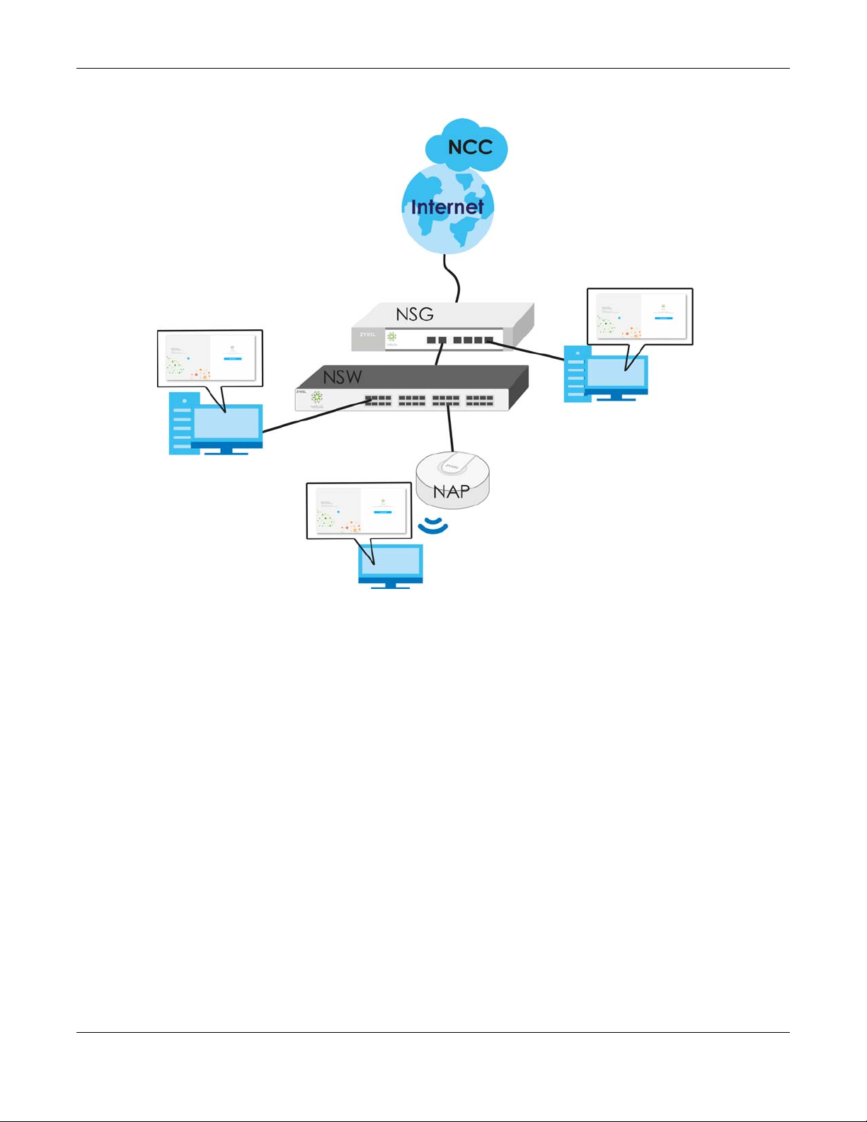
Chapter 1 Getting to Know Your Switch
See the NCC (Nebula Control Center) User’s Guide for how to configure the Switch using Nebula.
1.1.5 Mode Changing
This section describes how to change the Switch’s management mode.
Note: Hybrid mode and NCC registration are reserved for future use.
Note: When you change the Switch’s management mode from standalone mode to Nebula-
manged mode, the configuration settings of the Switch will be overwritten with what
you have configured in Nebula.
When you change the Switch’s management mode from Nebula-manged mode to
standalone mode, the Switch will reset to its factory-default settings.
From Standalone to Nebula Cloud Management
To manage your Switch via Nebula, connect the Switch to the Internet, and register it to a site and
organization at the Nebula web portal (https://nebula.zyxel.com).
See the following steps or the Switch Quick Start Guide for how to do device registration.
Go to the NCC to Register the Switch
1 Go to the Nebula web portal in one of three ways.
XS3800-28 User’s Guide
26
Page 27

Chapter 1 Getting to Know Your Switch
• Type https://nebula.zyxel.com in a supported web browser. See the Nebula User’s Guide for more
information about supported browsers.
• Click the Visit button in the Switch’s login page.
• Click the Nebula icon in the upper right corner of the Switch’s web configurator.
2 Click Login in the Nebula web portal. Enter your myZyxel account information. You’ll be redirected to
another screen where you can sign up for a myZyxel account if you don’t have one.
3 Use the Nebula setup wizard to create an organization and a site.
4 Register the Switch by entering its MAC address and serial number. The serial number and MAC address
can be found in the Status screen or the device back label on the Switch.
Use the Zyxel Nebula Mobile App to Register the Switch
1 Download and open the Zyxel Nebula Mobile app in your mobile device. Click Sign Up to create a
myZyxel account or enter your existing account information to log in.
2 You should already have created an organization and a site.
3 Select a site and scan the Switch's QR code to add it to the site. You can find the QR code:
• On a label on the Switch or
• On its box or
• In the web configurator at Basic > Cloud Management > Nebula Switch Registration.
See Section 3.3 on page 40 for more information about the CLOUD LED or Section 7.2 on page 75 for
more information about the Hybrid Mode field in the Status screen to see if the Switch goes into Nebula
cloud management mode successfully.
Note: The Switch goes into Nebula-managed mode automatically after it can access the
Nebula web portal and is successfully registered there. Its login password and settings
are then overwritten with what you have configured in the Nebula web portal.
From Nebula-managed to Standalone
To return to direct management standalone mode, just click Unregister to remove the Switch from the
organization/site in the Nebula web portal. The Switch will reboot and restore the factory default
settings.
1.1.6 ZON Utility
With its built-in web configurator, including the Neighbor Management feature (Section 7.3 on page 77),
viewing, managing and configuring the Switch and its neighboring devices is easy.
In addition, Zyxel offers a proprietary software program called Zyxel One Network (ZON) Utility, it is a
utility tool that assists you to set up and maintain network devices in a more simple and efficient way.
You can download the ZON Utility at www.zyxel.com and install it on a PC (Windows operating system).
For more information on ZON Utility see Section 4.3 on page 46.
The following table shows which firmware version supports ZON and Neighbor Management (Smart
Connect) for each Switch. The firmware on each Switch is identified by the firmware trunk version,
followed by a unique model code and release number in brackets. For example, 4.60(ABML.0) is a
XS3800-28 User’s Guide
27
Page 28
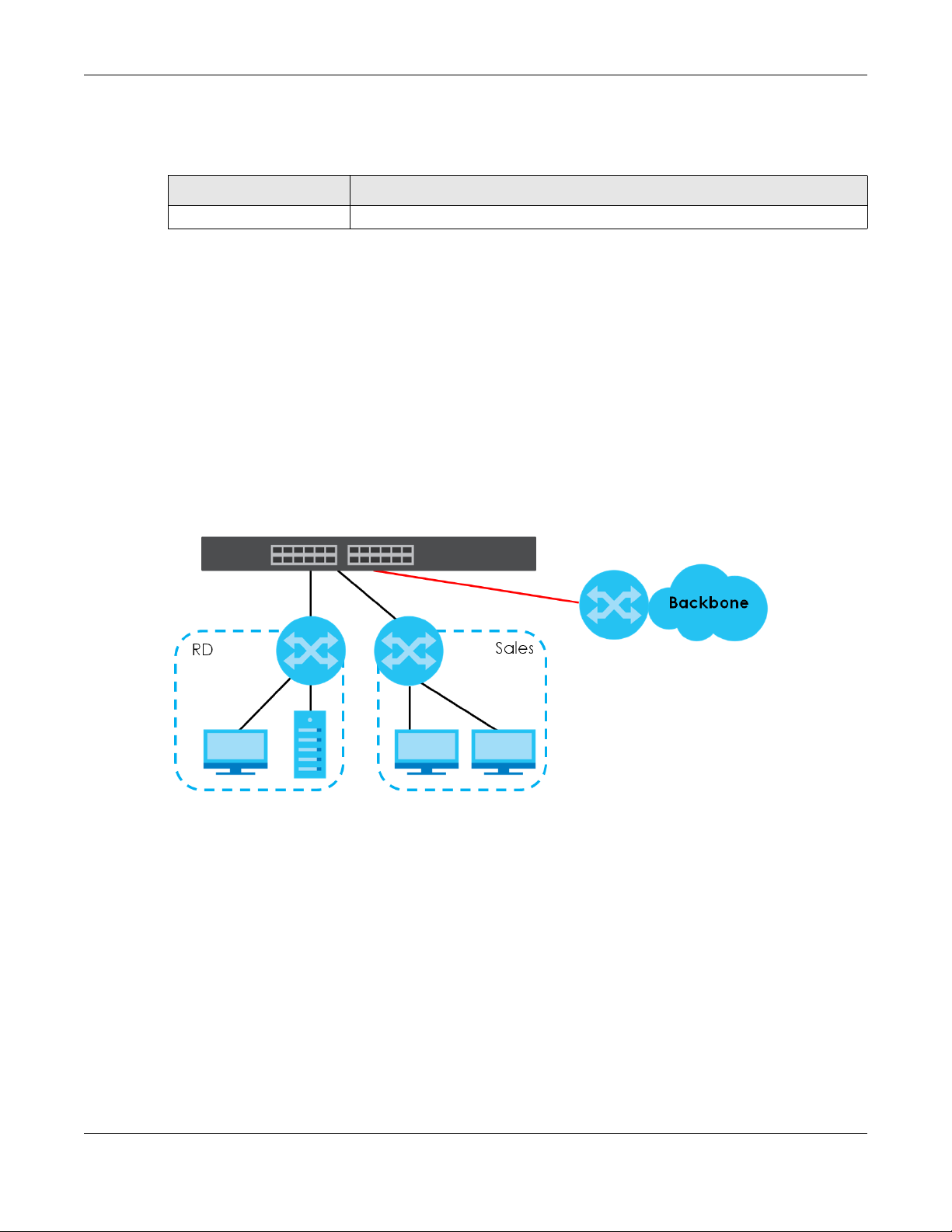
firmware version for the Switch where 4.60 is the firmware trunk version, ABML identifies the Switch and .0
is the first release of trunk version 4.60.
Table 2 Models and Firmware Version
SWITCH MODEL FIRMWARE VERSION
XS3800-28 4.60(ABML.0) and later
1.2 Applications
This section shows a few examples of using the Switch in various network environments.
1.2.1 Bridging Example
In this example the Switch connects different company departments (RD and Sales) to the corporate
backbone. It can alleviate bandwidth contention and eliminate server and network bottlenecks. All
users that need high bandwidth can connect to high-speed department servers via the Switch. You can
provide a super-fast uplink connection by using the 10 Gigabit uplink ports on the Switch.
Chapter 1 Getting to Know Your Switch
Figure 4 Bridging Application
1.2.2 High Performance Switching Example
The Switch is ideal for connecting two geographically dispersed networks that need high bandwidth. In
the following example, a company uses the 10 Gigabit uplink ports to connect the headquarters to a
branch office network. Within the headquarters network, a company can use trunking to group several
physical ports into one logical higher-capacity link. Trunking can be used if for example, it is cheaper to
use multiple lower-speed links than to under-utilize a high-speed, but more costly, single-port link.
XS3800-28 User’s Guide
28
Page 29
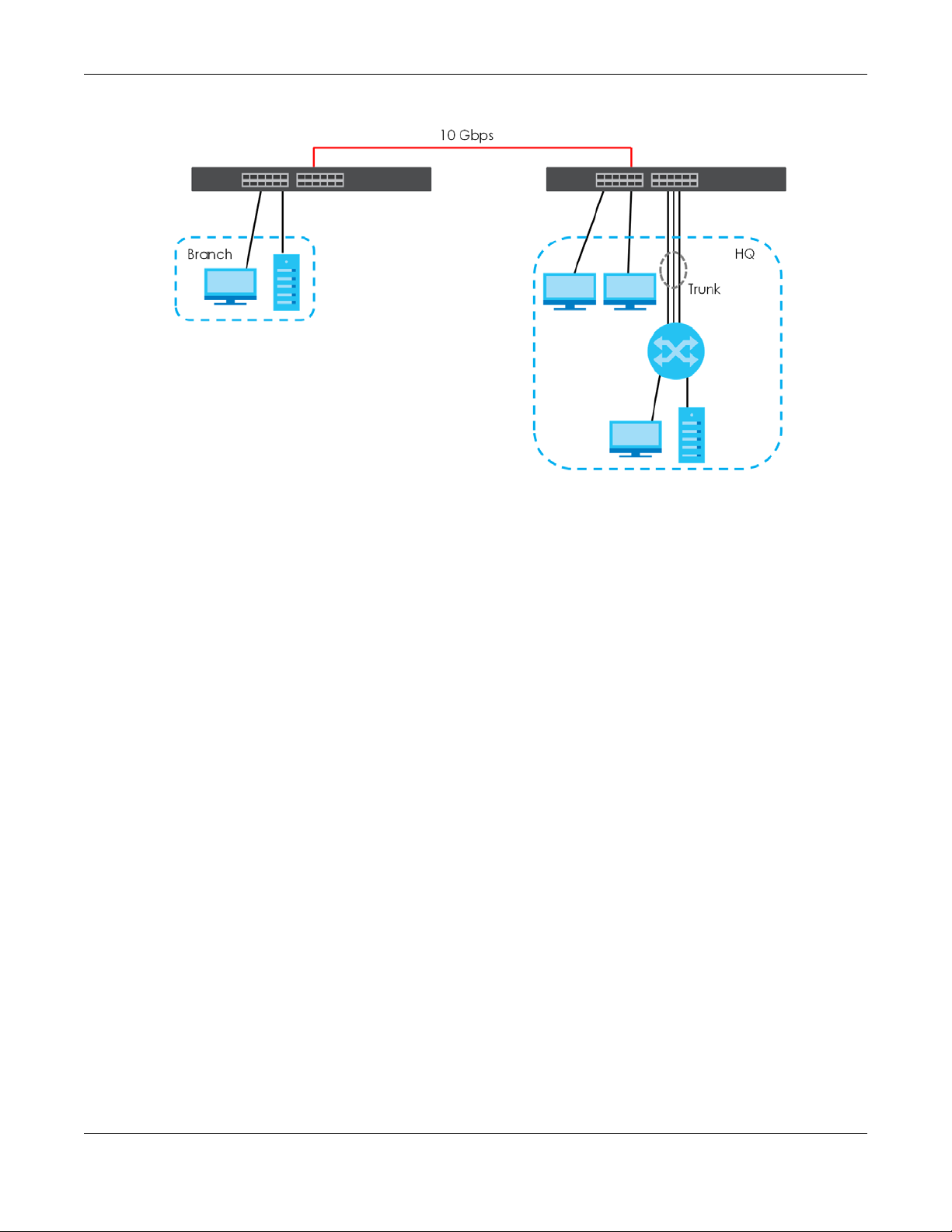
Chapter 1 Getting to Know Your Switch
Figure 5 High Performance Switching
1.2.3 IEEE 802.1Q VLAN Application Example
A VLAN (Virtual Local Area Network) allows a physical network to be partitioned into multiple logical
networks. Stations on a logical network belong to one or more groups. With VLAN, a station cannot
directly talk to or hear from stations that are not in the same group(s) unless such traffic first goes through
a router.
For more information on VLANs, refer to Chapter 9 on page 119.
1.2.3.1 Tag-based VLAN Example
Ports in the same VLAN group share the same frame broadcast domain, thus increasing network
performance by reducing broadcast traffic. VLAN groups can be modified at any time by adding,
moving or changing ports without any re-cabling.
Shared resources such as a server can be used by all ports in the same VLAN as the server. In the
following figure only ports that need access to the server need to be part of VLAN 1. Ports can belong to
other VLAN groups too.
XS3800-28 User’s Guide
29
Page 30
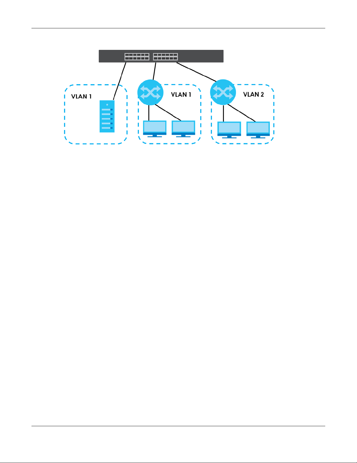
Figure 6 Shared Server Using VLAN Example
1.2.4 IPv6 Support
Chapter 1 Getting to Know Your Switch
IPv6 (Internet Protocol version 6), is designed to enhance IP address size and features. The increase in
IPv6 address size to 128 bits (from the 32-bit IPv4 address) allows up to 3.4 x 10
of writing, the Switch supports the following features.
• Static address assignment and stateless auto-configuration
• Neighbor Discovery Protocol (a protocol used to discover other IPv6 devices in a network)
• Remote Management using ping SNMP, telnet, HTTP and FTP services
• ICMPv6 to report errors encountered in packet processing and perform diagnostic functions, such as
"ping”
• IPv4/IPv6 dual stack; the Switch can run IPv4 and IPv6 at the same time
• DHCPv6 client and relay
• Multicast Listener Discovery (MLD) snooping and proxy
For more information on IPv6, refer to Appendix C on page 571 and the CLI Reference Guide.
1.3 Ways to Manage the Switch
Use any of the following methods to manage the Switch.
• Web Configurator. This is recommended for everyday management of the Switch using a (supported)
web browser. See Chapter 4 on page 43.
• Command Line Interface. Line commands offer an alternative to the Web Configurator and may be
necessary to configure advanced features. See the CLI Reference Guide.
• FTP. Use File Transfer Protocol for firmware upgrades and configuration backup/restore. See Section
51.11 on page 492.
• SNMP. The device can be monitored and/or managed by an SNMP manager. See Section 52.3 on
page 496.
38
IP addresses. At the time
XS3800-28 User’s Guide
30
Page 31

Chapter 1 Getting to Know Your Switch
1.4 Good Habits for Managing the Switch
Do the following things regularly to make the Switch more secure and to manage the Switch more
effectively.
• Change the password. Use a password that’s not easy to guess and that consists of different types of
characters, such as numbers and letters.
• Write down the password and put it in a safe place.
• Back up the configuration (and make sure you know how to restore it). Restoring an earlier working
configuration may be useful if the device becomes unstable or even crashes. If you forget your
password, you will have to reset the Switch to its factory default settings. If you backed up an earlier
configuration file, you would not have to totally re-configure the Switch. You could simply restore your
last configuration.
XS3800-28 User’s Guide
31
Page 32

Hardware Installation and
This chapter shows you how to install and connect the Switch.
2.1 Freestanding Installation
1 Make sure the Switch is clean and dry.
2 Remove the adhesive backing from the rubber feet.
3 Attach the rubber feet to each corner on the bottom of the Switch. These rubber feet help protect the
Switch from shock or vibration and ensure space between devices when stacking.
Figure 7 Attaching Rubber Feet
CHAPTER 2
Connection
4 Set the Switch on a smooth, level surface strong enough to support the weight of the Switch and the
connected cables. Make sure there is a power outlet nearby.
5 Make sure there is at least 40 mm of clearance around the Switch to allow air circulation and the
attachment of cables and the power cord.
Do NOT block the ventilation holes nor store things on the Switch. Allow
clearance for the ventilation holes to prevent your Switch from
overheating. Overheating could affect the performance of your Switch,
or even damage it.
XS3800-28 User’s Guide
32
Page 33

Chapter 2 Hardware Installation and Connection
2.2 Rack Mounting
The Switch can be mounted on an EIA standard size, 19-inch rack or in a wiring closet with other
equipment. Follow the steps below to mount your Switch on a standard EIA rack using a rack-mounting
kit.
Note: Make sure there is enough clearance between each equipment on the rack for air
circulation.
2.2.1 Installation Requirements
• Two mounting brackets.
• Eight M3 flat head screws and a #2 Philips screwdriver.
• Four M5 flat head screws and a #2 Philips screwdriver.
2.2.1.1 Precautions
• Make sure the rack will safely support the combined weight of all the equipment it contains. The
maximum weight a bracket can hold is 21.5 Kg.
• Make sure the position of the Switch does not make the rack unstable or top-heavy. Take all
necessary precautions to anchor the rack securely before installing the unit.
2.2.2 Attaching the Mounting Brackets to the Switch
1 Position a mounting bracket on one side of the Switch, lining up the four screw holes on the bracket with
the screw holes on the side of the Switch.
Figure 8 Attaching the Mounting Brackets
2 Using a #2 Philips screwdriver, install the M3 flat head screws through the mounting bracket holes into
the Switch.
3 Repeat steps 1 and 2 to install the second mounting bracket on the other side of the Switch.
4 You may now mount the Switch on a rack. Proceed to the next section.
XS3800-28 User’s Guide
33
Page 34

Chapter 2 Hardware Installation and Connection
2.2.3 Mounting the Switch on a Rack
1 Position a mounting bracket (that is already attached to the Switch) on one side of the rack, lining up
the two screw holes on the bracket with the screw holes on the side of the rack.
Figure 9 Mounting the Switch on a Rack
2 Using a #2 Philips screwdriver, install the M5 flat head screws through the mounting bracket holes into
the rack.
Note: Make sure you tighten all the four screws to prevent the Switch from getting slanted.
3 Repeat steps 1 and 2 to attach the second mounting bracket on the other side of the rack.
XS3800-28 User’s Guide
34
Page 35

Hardware Overview
This chapter describes the front panel and rear panel of the Switch and shows you how to make the
hardware connections.
3.1 Front Panel Connections
The Switch supports 16 SFP+ slots and four 10 Gigabit Ethernet ports. The Switch also comes with eight
dual personality interfaces of 10 Gigabit. A dual personality interface includes one Gigabit port and one
slot for a SFP+ module with one port active at a time.
Ethernet ports support Multi-Gigabit (100 Mbps, 1 Gbps, 2.5 Gbps, 5 Gbps, and 10 Gbps). See Section
1.1.1 on page 23 for more information about Multi-Gigabit.
The figure below shows the front panel of the Switch.
CHAPTER 3
Figure 10 Front Panel: XS3800-28
The following table describes the ports.
Table 3 Panel Connections
CONNECTOR DESCRIPTION
16 10 GbE SFP+ Slots Use SFP+ transceivers in these ports for high-bandwidth backbone connections. You can
4 100 Mbps, 1 Gbps,
2.5 Gbps, 5 Gbps,
and 10 Gbps RJ-45
Ethernet Ports
8 10 GbE Combo
Ports (Dual
Personality
Interfaces)
RJ-45 out-of-band
Management Port
Console Port Only connect this port to your computer (using an RS-232 cable) if you want to configure the
also insert an SFP+ Direct Attach Copper (DAC) in the SFP+ slot.
These are 10GBase-T auto-negotiating and auto-crossover Ethernet ports.
Connect these ports to a computer, a hub, a router, or an Ethernet switch.
Each interface has one 10GBase-T copper RJ-45 port and one SFP slot, with one port active
at a time.
• 8 10GBase-T Ports:
Connect these ports to a computer, an Ethernet switch or router.
•8 SFP+ Slots:
Use Small Form-Factor Pluggable (SFP) transceivers in these ports for fiber-optic
connections to an Ethernet switch or router.
Connect to a computer using an RJ-45 Ethernet cable for local configuration of the Switch.
Switch using the command line interface (CLI) via the console port.
XS3800-28 User’s Guide
35
Page 36

Table 3 Panel Connections (continued)
CONNECTOR DESCRIPTION
Reset Press the RESET button to reboot the Switch without turning the power off. See Section 3.3 on
RESTORE Press the RESTORE button for three to six seconds to have the Switch automatically reboot
3.1.1 SFP/SFP+ Slots
The transceiver slots are for Small Form-Factor Pluggable (SFP), SFP+ transceivers or DAC (Direct Attach
Cables) cable. The SFP+ (SFP Plus) and the DAC cable are enhanced versions of the SFP and support
data rates of up to 10 Gbps. A transceiver is a single unit that houses a transmitter and a receiver. Use a
transceiver or a DAC cable to connect a fiber-optic cable to the Switch. The Switch does not come with
transceivers nor DAC cables. You must use transceivers or DAC cables that comply with the Small Formfactor Pluggable (SFP) Transceiver MultiSource Agreement (MSA). See the SFF committee’s INF-8074i
specification Rev 1.0 for details.
Chapter 3 Hardware Overview
page 40 for more information about the LED behavior.
and restore the last-saved custom default file. See Section 3.3 on page 40 for more
information about the LED behavior.
Press the RESTORE button for more than seven seconds to have the Switch automatically
reboot and restore the factory default file. See Section 3.3 on page 40 for more information
about the LED behavior.
You can change transceivers or the DAC cables while the Switch is operating. You can use different
transceivers to connect to Ethernet switches with different types of fiber-optic connectors.
• Type: SFP connection interface
• Connection speed: 1 Gigabit per second (Gbps)
• Type: SFP+/DAC connection interface
• Connection speed: 1 or 10 Gigabit per second (Gbps)
To avoid possible eye injury, do not look into an operating fiber-optic
module’s connectors.
3.1.1.1 Transceiver Installation
Use the following steps to install a transceiver.
1 Insert the transceiver into the slot with the exposed section of PCB board facing down.
Figure 11 Transceiver Installation Example
2 Press the transceiver firmly until it clicks into place.
XS3800-28 User’s Guide
36
Page 37

3 The Switch automatically detects the installed transceiver. Check the LEDs to verify that it is functioning
properly.
Figure 12 Installed Transceiver
3.1.1.2 Transceiver Removal
Use the following steps to remove a transceiver.
1 Open the transceiver’s latch (latch styles vary).
Figure 13 Opening the Transceiver’s Latch Example
Chapter 3 Hardware Overview
2 Pull the transceiver out of the slot.
Figure 14 Transceiver Removal Example
3.1.2 Ethernet Ports
The Switch has 10GBase-T auto-negotiating, auto-crossover Ethernet ports. In Multi-Gigabit Ethernet, the
speed can be 100 Mbps, 1 Gbps, 2.5 Gbps, 5 Gbps, or 10 Gbps. See Section 1.1.1 on page 23 for more
information about Multi-Gigabit. The duplex mode can be full duplex at 100 Mbps and full duplex only at
1000 Mbps.
An auto-negotiating port can detect and adjust to the optimum Ethernet speed (100 Mbps, 1 Gbps, 2.5
Gbps, 5 Gbps, and 10 Gbps) and full duplex mode of the connected device.
An auto-crossover (auto-MDI/MDI-X) port automatically works with a straight-through or crossover
Ethernet cable.
When auto-negotiation is turned on, an Ethernet port negotiates with the peer automatically to
determine the connection speed and duplex mode. If the peer Ethernet port does not support autonegotiation or turns off this feature, the Switch determines the connection speed by detecting the signal
XS3800-28 User’s Guide
37
Page 38

Chapter 3 Hardware Overview
on the cable. When the Switch’s auto-negotiation is turned off, an Ethernet port uses the pre-configured
speed and duplex mode when making a connection, thus requiring you to make sure that the settings
of the peer Ethernet port are the same in order to connect.
3.1.2.1 Default Ethernet Settings
The factory default negotiation settings for the Ethernet ports on the Switch are:
• Speed: Auto
•Duplex: Auto
• Flow control: Off
• Dual Personality Interface: Fiber-optic module first
3.1.3 Dual Personality Interfaces
A combo port is for uplink connections. It consists of a 10 Gigabit Ethernet port for Ethernet connection,
and a SFP+ transceiver slot for fiber connection. The fiber connection takes priority if the corresponding
Gigabit port is also connected.
• 100 Mbps/1 Gbps/2.5 Gbps/5 Gbps/10 Gbps - Connect these ports to high-bandwidth backbone
network Ethernet switches using Category 5e/6/6a/7 copper cables, see Table 1 on page 24 for more
information about the cable differences.
• Transceiver Slots - Use SFP/SFP+ in these slots for connections to backbone Ethernet switches.
Figure 15 Combo Port Example: 10 Gigabit Port and SFP+ Transceiver Slot
3.1.4 Management Port
The 1000Base-T Ethernet MGMT (management) port is used for local management. Connect directly to
this port using an Ethernet cable. You can configure the Switch via Telnet or the web configurator.
The default IP address of the management port is 192.168.0.1 with a subnet mask of 255.255.255.0.
3.1.5 Console Port
For local management, you can use a computer with terminal emulation software configured to the
following parameters:
• VT100 terminal emulation
• 115200 bps
• No parity, 8 data bits, 1 stop bit
• No flow control
XS3800-28 User’s Guide
38
Page 39

Connect the male 9-pin end of the RS-232 console cable to the console port of the Switch. Connect the
B
A
female end to a serial port (COM1, COM2 or other COM port) of your computer.
3.2 Rear Panel
The following figures show the rear panels of the Switch. The rear panels contain:
• Two AC power receptacles (A and B)
Figure 16 Rear Panel: XS3800-28
3.2.1 Grounding
Grounding is a safety measure to have unused electricity return to the ground. It prevents damage to
the Switch, and protects you from electrocution.
Chapter 3 Hardware Overview
Note: The Switch must be grounded by qualified service personnel.
1 Remove the M4 ground screw from the Switch’s rear panel.
2 Secure a green/yellow ground cable (16 AWG or smaller) to the Switch's rear panel using the M4 ground
screw.
3 Attach the other end of the cable to the ground, either to the same ground electrode as the rack you
installed the device on or to the main grounding electrode of the building.
Follow your country's regulations and safety instructions to electrically ground the device properly.
Warning! Connect the ground cable before you connect any other
cables or wiring.
Figure 17 Grounding
XS3800-28 User’s Guide
39
Page 40

3.2.2 AC Power Connection
Make sure you are using the correct power source and that no objects obstruct the airflow of the fans.
The Switch uses two power supply modules, one of which is redundant, so if one power module fails the
system can operate on the remaining module.
Connecting the Power
Use the following procedures to connect the Switch to a power source after you have installed it in a
rack.
Note: Use the included power cord for the AC power connection.
1 Connect the female end of the power cord to the AC power socket.
2 Connect the other end of the cord to a power outlet.
Disconnecting the Power
Chapter 3 Hardware Overview
The power input connectors can be disconnected from the power source individually.
1 Disconnect the power cord from the power outlet.
2 Disconnect the power cord from the AC power socket.
3.3 LEDs
The following table describes the LEDs.
Table 4 LEDs
LED COLOR STATUS DESCRIPTION
PWR1 Green On The Switch is receiving power from the power module in the first power
slot.
Blinking The Switch is returning to the last-saved custom default configuration
settings.
Amber On The Switch is returning to its factory default configuration settings.
Blinking The PWR1 LED will blink in amber in the following situations:
• The Switch detected a power supply failure with the power cable
connected to the Switch and a power source.
• The fans are not functioning at a proper speed or malfunctioning.
Off The Switch is not receiving power from the power module in the first
power slot.
XS3800-28 User’s Guide
40
Page 41

Chapter 3 Hardware Overview
Table 4 LEDs (continued)
LED COLOR STATUS DESCRIPTION
PWR2 Green On The Switch is receiving power from the power module in the second
power slot.
Blinking The Switch is returning to the last-saved custom default configuration
settings.
Amber On The Switch is returning to its factory default configuration settings.
Blinking The PWR2 LED will blink in amber in the following situations:
• The Switch detected a power supply failure with the power cable
connected to the Switch and a power source.
• The fans are not functioning at a proper speed or malfunctioning.
Off The Switch is not receiving power from the power module in the second
SYS (System) Green On The Switch is on and functioning properly.
Blinking The Switch is rebooting and performing self-diagnostic tests.
Red On The Switch is functioning abnormally.
Off The power is off or the system is not ready/malfunctioning.
CLOUD Green On The Switch has successfully connected to the NCC (Nebula Control
Blinking The Switch cannot connect to the NCC because it is not registered.
Amber On The Switch is registered at the NCC but cannot connect to the NCC.
Blinking The Switch is not registered at the NCC and cannot connect to the NCC.
Off The Switch is operating in standalone mode. Nebula Control Center
power slot.
Center).
Please check the Internet connection of the Switch.
Please check the Internet connection of the Switch and register the
Switch at NCC.
Discovery is disabled in Basic > Cloud Management > Nebula Control
Center Discovery in the Switch Web Configurator.
Note: Hybrid mode and NCC registration are reserved for future use.
LOCATOR Blue On The Switch is uploading firmware. While the Switch is doing this, don’t turn
Blinking Shows the actual location of the Switch between several devices in a
Off The locator is not functioning or malfunctioning.
MAST
(Master)
Ethernet Ports
17-28 Green On The port has a successful 100 Mbps/1 Gbps/2.5 Gbps/5 Gbps connection.
SFP+ Slots
Green On The Switch is acting as a standalone switch or the master in stacking.
Off The Switch is acting as a non-master member in a stack or it is in
Amber On There is an error occurred when the Switch is selected as the master
Blinking The port is receiving or transmitting data at 100 Mbps/1 Gbps/2.5 Gbps/5
Blue On The port has a successful 10 Gbps connection.
Blinking The port is receiving or transmitting data at 10 Gbps.
Off This link is disconnected or the port is disabled.
off the power.
rack. The default timer is 30 minutes when you are configuring the Switch.
standalone mode.
member in a stack.
Gbps.
XS3800-28 User’s Guide
41
Page 42

Chapter 3 Hardware Overview
Table 4 LEDs (continued)
LED COLOR STATUS DESCRIPTION
1-16; 21-28 Green On The port has a successful 1000 Mbps connection.
Blinking The port is receiving or transmitting data at 1000 Mbps.
Blue On The port has a successful 10 Gbps connection.
Blinking The port is receiving or transmitting data 10 Gbps.
Off This link is disconnected.
MGMT
(Manageme
nt)
STACK ID The LED is showing the Stack ID number of the Switch.
Green
(Right)
Amber
(Left)
On The MGMT port is connected at 10/1000 Mbps.
Blinking The system is transmitting or receiving to/from an Ethernet device at 10/
1000 Mbps through the MGMT port.
On The MGMT port is connected at 100 Mbps.
Blinking The system is transmitting or receiving to/from an Ethernet device at 100
Mbps through the MGMT port.
Off The MGMT port is not connected to an Ethernet device, or the port is
disabled.
ID 0 means it is a standalone Switch.
XS3800-28 User’s Guide
42
Page 43

The Web Configurator
This section introduces the configuration and functions of the web configurator.
4.1 Introduction
The web configurator is an HTML-based management interface that allows easy Switch setup and
management via Internet browser. Supported browsers at the time of writing are:
•IE 8 or later
• Chrome 34.0.1847.131 or later
• Firefox 29.0.1 or later
• Opera 21.0 or later
• Safari 5.1.7 or later
CHAPTER 4
The recommended screen resolution is 1024 by 768 pixels. In order to use the web configurator you need
to allow:
• Web browser pop-up windows from your device. Web pop-up blocking is enabled by default in some
browsers.
• JavaScript (enabled by default).
• Java permissions (enabled by default).
4.2 System Login
1 Start your web browser.
2 The Switch is a DHCP client by default. Type “http://DHCP-assigned IP” in the Location or Address field.
Press [ENTER].
If the Switch is not connected to a DHCP server, type “http://” and the static IP address of the Switch (for
example, the default management IP address is 192.168.1.1 through an in-band (non-MGMT) port and
192.168.0.1 through the MGMT port) in the Location or Address field. Press [ENTER]. Your computer must
be in the same subnet in order to access this website address.
Also, you can use the ZON Utility to check your Switch’s IP address. See Section 4.3 on page 46 for more
information on the ZON utility.
3 The following screen appears.
XS3800-28 User’s Guide
43
Page 44

Chapter 4 The Web Configurator
Figure 18 Web Configurator: Login
4 Click Login to log into the web configurator to manage the Switch directly. The default username is
admin and associated default password is 1234.
5 If Nebula Control Center Discovery is enabled, you will see the following screen encouraging you to use
NCC after you log in to the web configurator. The screen has a QR code containing the Switch’s serial
number and MAC address for handy NCC registration of the Switch using the Nebula Mobile app. First,
download the app from the Google Play store for Android devices or the App Store for iOS devices and
create an organization and site at NCC.
Figure 19 Web Configurator: Message
You may also access this screen at Basic Setting > Cloud Management > Nebula Switch Registration.
6 If you didn’t change the default administrator password and/or SNMP community values, a warning
screen displays each time you log into the web configurator. Click Password / SNMP to open a screen
where you can change the administrator and SNMP passwords simultaneously. Otherwise, click Ignore
to close it.
XS3800-28 User’s Guide
44
Page 45

Chapter 4 The Web Configurator
Figure 20 Web Configurator: Warning
Figure 21 Web Configurator: Password/SNMP
Change the default administrator and/or SNMP passwords, and then click Apply to save your changes.
Table 5 Web Configurator: Password/SNMP
LABEL DESCRIPTION
Administrator
This is the default administrator account with the “admin” user name. You cannot change the default administrator
user name.
Old Password Type the existing system password (1234 is the default password when shipped).
New Password Enter your new system password.
Retype to confirm Retype your new system password for confirmation
General Setting
Use this section to specify the SNMP version and community (password) values.
Version Select the SNMP version for the Switch. The SNMP version on the Switch must match the version
on the SNMP manager. Choose SNMP version 2c (v2c), SNMP version 3 (v3) or both (v3v2c).
Note: SNMP version 2c is backwards compatible with SNMP version 1.
Get Community Enter the Get Community string, which is the password for the incoming Get- and GetNext-
requests from the management station.
The Get Community string is only used by SNMP managers using SNMP version 2c or lower.
XS3800-28 User’s Guide
45
Page 46

Chapter 4 The Web Configurator
Table 5 Web Configurator: Password/SNMP (continued)
LABEL DESCRIPTION
Set Community Enter the Set Community string, which is the password for the incoming Set- requests from the
management station.
The Set Community string is only used by SNMP managers using SNMP version 2c or lower.
Trap Community Enter the Trap Community string, which is the password sent with each trap to the SNMP
manager.
The Trap Community string is only used by SNMP managers using SNMP version 2c or lower.
Apply Click Apply to save your changes to the Switch’s run-time memory. The Switch loses these
changes if it is turned off or loses power, so use the Save link on the top navigation panel to
save your changes to the non-volatile memory when you are done configuring.
Cancel Click Cancel to begin configuring this screen afresh.
4.3 Zyxel One Network (ZON) Utility
ZON Utility is a program designed to help you deploy and manage a network more efficiently. It detects
devices automatically and allows you to do basic settings on devices in the network without having to
be near it.
The ZON Utility issues requests via Zyxel Discovery Protocol (ZDP) and in response to the query, the device
responds back with basic information including IP address, firmware version, location, system and model
name in the same broadcast domain. The information is then displayed in the ZON Utility screen and you
can perform tasks like basic configuration of the devices and batch firmware upgrade in it. You can
download the ZON Utility at www.zyxel.com and install it on a PC (Windows operating system).
4.3.1 Requirements
Before installing the ZON Utility on your PC, please make sure it meets the requirements listed below.
Operating System
At the time of writing, the ZON Utility is compatible with:
• Windows 7 (both 32-bit / 64-bit versions)
• Windows 8 (both 32-bit / 64-bit versions)
• Windows 8.1 (both 32-bit / 64-bit versions)
• Window 10 (both 32-bit / 64-bit versions)
Note: To check for your Windows operating system version, right-click on My Computer >
Properties. You should see this information in the General tab.
Hardware
Here are the minimum hardware requirements to use the ZON Utility on your PC.
• Core i3 processor
•2GB RAM
XS3800-28 User’s Guide
46
Page 47

• 100MB free hard disk
• WXGA (Wide XGA 1280x800)
4.3.2 Run the ZON Utility
1 Double-click the ZON Utility to run it.
2 The first time you run the ZON Utility, you will see if your device and firmware version support the ZON
Utility. Click the OK button to close this screen.
Figure 22 Supported Devices and Versions
Chapter 4 The Web Configurator
If you want to check the supported models and firmware versions later, you can click the Show
information about ZON icon in the upper right hand corner of the screen. Then select the Supported
model and firmware version link. If your device is not listed here, see the device release notes for ZON
utility support. The release notes are in the firmware zip file on the Zyxel web site.
XS3800-28 User’s Guide
47
Page 48

Chapter 4 The Web Configurator
1
2
3
4
56
7
8
9
10 11 12 13
Figure 23 ZON Utility Screen
3 Select a network adapter to which your supported devices are connected.
4 Click the Go button for the ZON Utility to discover all supported devices in your network.
Figure 24 Discovery
5 The ZON Utility screen shows the devices discovered.
Figure 25 ZON Utility Screen
6 Select a device and then use the icons to perform actions. Some functions may not be available for
your devices.
Note: You must know the selected device admin password before taking actions on the
device using the ZON utility icons.
XS3800-28 User’s Guide
48
Page 49

Chapter 4 The Web Configurator
Figure 26 Password Prompt
The following table describes the icons numbered from left to right in the ZON Utility screen.
Table 6 ZON Utility Icons
ICON DESCRIPTION
1 IP configuration Change the selected device’s IP address.
2 Renew IP Address Update a DHCP-assigned dynamic IP address.
3 Reboot Device Use this icon to restart the selected device(s). This may be useful when troubleshooting
or upgrading new firmware.
4 Reset Configuration to
Default
5 Locator LED Use this icon to locate the selected device by causing its Locator LED to blink.
6 Web GUI Use this to access the selected device web configurator from your browser. You will
7 Firmware Upgrade Use this icon to upgrade new firmware to selected device(s) of the same model.
If you forget your password or cannot access the Web Configurator, you can use this
icon to reload the factory-default configuration file. This means that you will lose all
configurations that you had previously.
need a username and password to log in.
Online upgrade: If there’s the latest firmware available, it’ll show in the drop-down
menu. You don’t need to download the firmware first to upgrade firmware.
Local upgrade: Make sure you have downloaded the firmware from the Zyxel website
to your computer and unzipped it in advance.
8 Change Password Use this icon to change the admin password of the selected device. You must know
the current admin password before changing to a new one.
9 Configure NCC
Discovery
10 ZAC Use this icon to run the Zyxel AP Configurator of the selected AP.
11 Clear and Rescan Use this icon to clear the list and discover all devices on the connected network again.
12 Save Configuration Use this icon to save configuration changes to permanent memory on a selected
13 Settings Use this icon to select a network adaptor for the computer on which the ZON utility is
You must have Internet access to use this feature. Use this icon to enable or disable the
Nebula Control Center (NCC) discovery feature on the selected device. If it’s
enabled, the selected device will try to connect to the NCC. Once the selected
device is connected to and has registered in the NCC, it’ll go into the Nebula cloud
management mode.
device.
installed, and the utility language.
XS3800-28 User’s Guide
49
Page 50

Chapter 4 The Web Configurator
The following table describes the fields in the ZON Utility main screen.
Table 7 ZON Utility Fields
LABEL DESCRIPTION
Type This field displays an icon of the kind of device discovered.
Model This field displays the model name of the discovered device.
Firmware Version This field displays the firmware version of the discovered device.
MAC Address This field displays the MAC address of the discovered device.
IP Address This field displays the IP address of an internal interface on the discovered device that first
System Name This field displays the system name of the discovered device.
Location This field displays where the discovered device is.
Status This field displays whether changes to the discovered device have been done
NCC Discovery This field displays if the discovered device supports the Nebula Control Center (NCC)
Serial Number Enter the admin password of the discovered device to display its serial number.
Hardware Version This field displays the hardware version of the discovered device.
received an ZDP discovery request from the ZON utility.
successfully. As the Switch does not support IP Configuration, Renew IP address and
Locator LED, this field displays “Update failed”, “Not support Renew IP address” and “Not
support Flash Locator LED” respectively.
discovery feature. If it’s enabled, the selected device will try to connect to the NCC. Once
the selected device is connected to and has registered in the NCC, it’ll go into the Nebula
cloud management mode.
4.4 The Web Configurator Layout
The Status screen is the first screen that displays when you access the web configurator.
The following figure shows the navigating components of a web configurator screen.
XS3800-28 User’s Guide
50
Page 51

Chapter 4 The Web Configurator
A
G
B
C
D
E
F
H
Figure 27 The Web Configurator Layout
A - Click the menu items to open submenu links, and then click on a submenu link to open the screen in
the main window.
B, C, D, E, F, G- These are quick links which allow you to perform certain tasks no matter which screen you
are currently working in.
B - Click this link to update the information in the screen you are viewing currently.
C - Click this link to save your configuration into the Switch’s nonvolatile memory. Nonvolatile memory is
saved in the configuration file from which the Switch booted from and it stays the same even if the
Switch’s power is turned off. See Section 51.3 on page 482 for information on saving your settings to a
specific configuration file.
D - Click this link to go to the status page of the Switch.
E - Click this link to log out of the web configurator.
F - Click this link to display web help pages. The help pages provide descriptions for all of the
configuration screens.
G - Click this link to go to the NCC (Nebula Control Center) portal website.
H - Click this link to go to the Neighbor screen where you can see and manage neighbor devices
learned by the Switch.
XS3800-28 User’s Guide
51
Page 52

Chapter 4 The Web Configurator
In the navigation panel, click a main link to reveal a list of submenu links.
Table 8 Navigation Panel Sub-links Overview
BASIC SETTING
ADVANCED
APPLICATION
IP APPLICATION MANAGEMENT
The following table describes the links in the navigation panel.
Table 9 Navigation Panel Links
LINK DESCRIPTION
Basic Settings
System Info This link takes you to a screen that displays general system and hardware monitoring
information.
General Setup This link takes you to a screen where you can configure general identification information and
time settings for the Switch.
Switch Setup This link takes you to a screen where you can set up global Switch parameters such as VLAN
IP Setup This link takes you to a screen where you can configure the IP address, subnet mask
type, MAC address learning, GARP and priority queues.
(necessary for Switch management) and set up to 128 IP routing domains.
XS3800-28 User’s Guide
52
Page 53

Chapter 4 The Web Configurator
Table 9 Navigation Panel Links (continued)
LINK DESCRIPTION
Port Setup This link takes you to screens where you can configure speed, flow control and priority settings
for individual Switch ports.
Interface Setup This link takes you to a screen where you can create virtual interfaces on the Switch.
IPv6 This link takes you to a screen where you can enable an IPv6 interface and configure the IPv6
settings on the Switch.
Stacking This link takes you to a screen where you can view and configure stacking system for the
DNS This link takes you to a screen where you can configure DNS (domain name server) IP
Cloud
Management
Advanced Application
VLAN This link takes you to screens where you can configure port-based or 802.1Q VLAN
Static MAC
Forwarding
Static Multicast
Forwarding
Filtering This link takes you to a screen to set up filtering rules.
Spanning Tree
Protocol
Bandwidth Control This link takes you to screens where you can cap the maximum bandwidth allowed on a port.
Broadcast Storm
Control
Mirroring This link takes you to screens where you can copy traffic from one port or ports to another port
Link Aggregation This link takes you to screen where you can logically aggregate physical links to form one
Port Authentication This link takes you to a screen where you can configure IEEE 802.1x port authentication as well
Port Security This link takes you to a screen where you can activate MAC address learning and set the
Time Range This link takes you to a screen where you can configure time range for time-oriented features
Classifier This link takes you to screens where you can configure the Switch to group packets based on
Policy Rule This link takes you to a screen where you can configure the Switch to perform special
Queuing Method This link takes you to a screen where you can configure queuing with associated queue
VLAN Stacking This link takes you to screens where you can activate and configure VLAN stacking.
Multicast This link takes you to screen where you can configure various multicast features, IGMP
Switch.
addresses.
This screen displays a link to a screen where you can enable or disable the Nebula Control
Center Discovery feature. If it’s enabled, you can have the Switch search for the NCC
(Nebula Control Center). Another link takes you to the Nebula Switch Registration screen
which has a QR code containing the Switch’s serial number and MAC address for handy
registration of the Switch at NCC.
(depending on what you configured in the Switch Setup menu). You can also configure a
protocol based VLAN or a subnet based VLAN in these screens.
This link takes you to screens where you can configure static MAC addresses for a port. These
static MAC addresses do not age out.
This link takes you to a screen where you can configure static multicast MAC addresses for
port(s). These static multicast MAC addresses do not age out.
This link takes you to screens where you can configure the RSTP/MRSTP/MSTP to prevent
network loops.
This link takes you to a screen to set up broadcast filters.
in order that you can examine the traffic from the first port without interference.
logical, higher-bandwidth link.
as MAC authentication for clients communicating via the Switch.
maximum number of MAC addresses to learn on a port.
like Classifier.
the specified criteria.
treatment on the grouped packets.
weights for each port.
snooping, MLD snooping-proxy and create multicast VLANs.
XS3800-28 User’s Guide
53
Page 54

Chapter 4 The Web Configurator
Table 9 Navigation Panel Links (continued)
LINK DESCRIPTION
AAA This link takes you to a screen where you can configure authentication, authorization and
accounting services via external servers. The external servers can be either RADIUS (Remote
Authentication Dial-In User Service) or TACACS+ (Terminal Access Controller Access-Control
System Plus).
IP Source Guard This link takes you to screens where you can configure filtering of unauthorized DHCP and ARP
packets in your network.
Loop Guard This link takes you to a screen where you can configure protection against network loops that
occur on the edge of your network.
VLAN Mapping This link takes you to screens where you can configure VLAN mapping settings on the Switch.
Layer 2 Protocol
Tunneling
sFlow This link takes you to screens where you can configure sFlow settings on the Switch.
PPPoE This link takes you to screens where you can configure how the Switch gives a PPPoE
Errdisable This link takes you to a screens where you can view errdisable status and configure errdisable
MAC Pinning This link takes you to a screen where you can set specific ports to have priority over other ports
Private VLAN This link takes you to a screen where you can block traffic between ports in a VLAN on the
Green Ethernet This link takes you to a screen where you can configure the Switch to reduce port power
LLDP This link takes you to a screen where you can configure LLDP settings.
Anti-Arpscan This link takes you to screens where you can enable anti-arpscan on the Switch and ports,
BPDU Guard This link takes you to screens where you can enable BPDU guard on the Switch and ports, and
OAM This link takes you to screens where you can enable Ethernet OAM on the Switch, view the
ZULD This link takes you to screens where you can enable ZULD on a port and configure related
NLB This link takes you to screens where you can configure to which MAC addresses and ports the
Wol Relay This link takes you to a screen where you can configure settings on Wake On LAN relay.
IP Application
Static Routing This link takes you to a screen where you can configure static routes. A static route defines
Policy Routing This link takes you to screens where you can configure policy routing rules.
DiffServ This link takes you to screens where you can enable DiffServ, configure marking rules and set
DHCP This link takes you to screens where you can configure the DHCP settings.
VRRP This link takes you to screens where you can configure redundant virtual router for your
Router Setup This link takes you to a screen where you can enable Equal-Cost MultiPath (ECMP) routing
This link takes you to a screen where you can configure L2PT (Layer 2 Protocol Tunneling)
settings on the Switch.
termination server additional subscriber information that the server can use to identify and
authenticate a PPPoE client.
settings in CPU protection, errdisable detect, and errdisable recovery.
in MAC address learning.
Switch.
consumption.
and view the port state. You can also create trusted hosts, view blocked hosts and unblock
them.
view the port state.
configuration of ports on which Ethernet OAM is enabled and perform remote-loopback
tests.
settings.
Switch should forward the incoming NLB traffic, and map the IP address to the MAC address
of a cluster for layer-3 forwarding.
how the Switch should forward traffic by configuring the TCP/IP parameters manually.
DSCP-to-IEEE802.1p mappings.
network.
and set the criteria the Switch uses to determine the routing path for a packet.
XS3800-28 User’s Guide
54
Page 55

Chapter 4 The Web Configurator
Table 9 Navigation Panel Links (continued)
LINK DESCRIPTION
ARP Setup This link takes you to a screen where you can configure ARP learning mode on a per-port
basis and create static ARP entries which do not age out.
Management
Maintenance This link takes you to screens where you can perform firmware and configuration file
maintenance as well as reboot the system.
Access Control This link takes you to screens where you can change the system login password and configure
Diagnostic This link takes you to screens where you can ping IP addresses, run traceroute, test port(s).
System Log This link takes you to a screen where you can view system logs.
Syslog Setup This link takes you to a screen where you can setup system logs and a system log server.
Cluster
Management
MAC Table This link takes you to a screen where you can view the MAC address and VLAN ID of a device
IP Table This link takes you to a screen where you can view the IP addresses and VLAN ID of a device
ARP Table This link takes you to a screen where you can view the MAC address – IP address resolution
Routing Table This link takes you to a screen where you can view the routing table.
Path MTU Table This link takes you to a screen where you can view the IPv6 path MTU table.
Configure Clone This link takes you to a screen where you can copy attributes of one port to (an)other port(s).
IPv6 Neighbor
Table
Port Status This link takes you to a screen where you can view the port statistics.
SNMP and remote management.
This link takes you to a screen where you can configure clustering management and view its
status.
attach to a port. You can also view what kind of MAC address it is.
attached to a port.You can also view what kind of device it is.
table.
This link takes you to a screen where you can view the Switch’s IPv6 neighbor table.
4.4.1 Change Your Password
After you log in for the first time, it is recommended you change the default administrator password.
Click Management > Access Control > Logins to display the next screen.
XS3800-28 User’s Guide
55
Page 56

Chapter 4 The Web Configurator
Figure 28 Change Administrator Login Password
4.5 Saving Your Configuration
When you are done modifying the settings in a screen, click Apply to save your changes back to the
run-time memory. Settings in the run-time memory are lost when the Switch’s power is turned off.
Click the Save link in the upper right hand corner of the web configurator to save your configuration to
nonvolatile memory. Nonvolatile memory refers to the Switch’s storage that remains even if the Switch’s
power is turned off.
Note: Use the Save link when you are done with a configuration session.
4.6 Switch Lockout
You could block yourself (and all others) from using in-band-management (managing through the data
ports) if you do one of the following:
1 Delete the management VLAN (default is VLAN 1).
2 Delete all port-based VLANs with the CPU port as a member. The “CPU port” is the management port of
the Switch.
3 Filter all traffic to the CPU port.
4 Disable all ports.
5 Misconfigure the text configuration file.
6 Forget the password and/or IP address.
XS3800-28 User’s Guide
56
Page 57

Chapter 4 The Web Configurator
7 Prevent all services from accessing the Switch.
8 Change a service port number but forget it.
9 You forgot to log out of the Switch from a computer before logging in again on another computer.
Note: Be careful not to lock yourself and others out of the Switch. If you do lock yourself out,
try using out-of-band management (via the management port) to configure the
Switch.
4.7 Resetting the Switch
If you lock yourself (and others) from the Switch or forget the administrator password, you will need to
reload the factory-default configuration file or reset the Switch back to the factory defaults.
4.7.1 Using the RESTORE Button
See Table 3 on page 35 to see how to use the RESTORE button to restore the factory default file.
4.7.2 Reload the Configuration File
Uploading the factory-default configuration file replaces the current configuration file with the factorydefault configuration file. This means that you will lose all previous configurations and the speed of the
console port will be reset to the default of 115200 bps with 8 data bit, no parity, one stop bit and flow
control set to none. The password will also be reset to “1234” and the IP address to 192.168.1.1 or DHCPassigned IP.
To upload the configuration file, do the following:
1 Connect to the console port using a computer with terminal emulation software. See Section 3.2 on
page 39 for details.
2 Disconnect and reconnect the Switch’s power to begin a session. When you reconnect the Switch’s
power, you will see the initial screen.
3 When you see the message “Press any key to enter Debug Mode within 3 seconds ...” press
any key to enter debug mode.
4 Type atlc after the “Enter Debug Mode” message.
5 Wait for the “Starting XMODEM upload” message before activating XMODEM upload on your
terminal.
6 After a configuration file upload, type atgo to restart the Switch.
XS3800-28 User’s Guide
57
Page 58

Chapter 4 The Web Configurator
Figure 29 Resetting the Switch: Via the Console Port
Bootbase Version: V1.00 | 02/21/2016 15:43:29
RAM: Size = 1048576 Kbytes
FLASH: 64M
ZyNOS Version: V4.60(ABML.0) | 04/18/2017 11:41:8
Press any key to enter debug mode within 1 second.
.....................................
Enter Debug Mode
ras> atlc
Starting XMODEM upload (CRC mode)....
CCCCCCCCCCCCCCCC
Total 393216 bytes received.
Erasing..
................................................................
OK
ras> atgo
The Switch is now reinitialized with a default configuration file including the default password of “1234”.
4.8 Logging Out of the Web Configurator
Click Logout in a screen to exit the web configurator. You have to log in with your password again after
you log out. This is recommended after you finish a management session for security reasons.
Figure 30 Web Configurator: Logout Screen
4.9 Help
The web configurator’s online help has descriptions of individual screens and some supplementary
information.
Click the Help link from a web configurator screen to view an online help description of that screen.
XS3800-28 User’s Guide
58
Page 59

Initial Setup Example
5.1 Overview
This chapter shows how to set up the Switch for an example network.
The following lists the configuration steps for the initial setup:
• Creating a VLAN
• Setting Port VID
• Configuring Switch Management IP Address
5.1.1 Creating a VLAN
VLANs confine broadcast frames to the VLAN group in which the port(s) belongs. You can do this with
port-based VLAN or tagged static VLAN with fixed port members.
CHAPTER 5
In this example, you want to configure port 1 as a member of VLAN 2.
Figure 31 Initial Setup Network Example: VLAN
1 Click Advanced Application > VLAN > VLAN Configuration in the navigation panel and click the Static
VLAN Setup link.
XS3800-28 User’s Guide
59
Page 60

Chapter 5 Initial Setup Example
2 In the Static VLAN screen, select ACTIVE, enter a
descriptive name in the Name field and enter 2 in the
VLAN Group ID field for the VLAN2 network.
Note: The VLAN Group ID field in this screen and the VID field in the IP Setup screen refer to the
same VLAN ID.
3 Since the VLAN2 network is connected to port 1 on the Switch, select Fixed to configure port 1 to be a
permanent member of the VLAN only.
4 To ensure that VLAN-unaware devices (such as computers and hubs) can receive frames properly, clear
the TX Tagging check box to set the Switch to remove VLAN tags before sending.
5 Click Add to save the settings to the run-time memory. Settings in the run-time memory are lost when the
Switch’s power is turned off.
5.1.2 Setting Port VID
Use PVID to add a tag to incoming untagged frames received on that port so that the frames are
forwarded to the VLAN group that the tag defines.
In the example network, configure 2 as the port VID on port 1 so that any untagged frames received on
that port get sent to VLAN 2.
XS3800-28 User’s Guide
60
Page 61

Chapter 5 Initial Setup Example
Figure 32 Initial Setup Network Example: Port VID
1 Click Advanced Applications > VLAN > VLAN
Configuration in the navigation panel. Then
click the VLAN Port Setup link.
2 Enter 2 in the PVID field for port 1 and click
Apply to save your changes back to the run-
time memory. Settings in the run-time memory
are lost when the Switch’s power is turned off.
5.1.3 Configuring Switch Management IP Address
The default management IP address of the Switch is 192.168.1.1. You can configure another IP address in
a different subnet for management purposes. The following figure shows an example.
XS3800-28 User’s Guide
61
Page 62

Chapter 5 Initial Setup Example
Figure 33 Initial Setup Example: Management IP Address
1 Connect your computer to any Ethernet port on the Switch. Make sure your computer is in the same
subnet as the Switch.
2 Open your web browser and enter 192.168.1.1 (the default IP address) in the address bar to access the
web configurator. See Section 4.2 on page 43 for more information.
3 Click Basic Setting > IP Setup > IP Configuration in the
navigation panel.
4 Configure the related fields in the IP Configuration
screen.
5 For the VLAN2 network, enter 192.168.2.1 as the IP
address and 255.255.255.0 as the subnet mask.
6 In the VID field, enter the ID of the VLAN group to
which you want this management IP address to
belong. This is the same as the VLAN ID you
configure in the Static VLAN screen.
7 Click Add to save your changes back to the run-time
memory. Settings in the run-time memory are lost
when the Switch’s power is turned off.
XS3800-28 User’s Guide
62
Page 63

CHAPTER 6
Tutorials
6.1 Overview
This chapter provides some examples of using the web configurator to set up and use the Switch. The
tutorials include:
• How to Use DHCPv4 Snooping on the Switch
• How to Use DHCPv4 Relay on the Switch
• How to Use Auto Configuration via a DHCP Server on the Switch
6.2 How to Use DHCPv4 Snooping on the Switch
You only want DHCP server A connected to port 5 to assign IP addresses to all devices in VLAN network
(V). Create a VLAN containing ports 5, 6 and 7. Connect a computer M to the Switch for management.
Figure 34 Tutorial: DHCP Snooping Tutorial Overview
Note: For related information about DHCP snooping, see Section 27.5 on page 298.
The settings in this tutorial are as the following.
Table 10 Tutorial: Settings in this Tutorial
HOST PORT CONNECTED VLAN PVID DHCP SNOOPING PORT TRUSTED
DHCP Server (A) 5 1 and 100 100 Yes
DHCP Client (B) 6 1 and 100 100 No
DHCP Client (C) 7 1 and 100 100 No
1 Access the Switch through http://192.168.1.1 by default. Log into the Switch by entering the username
(default: admin) and password (default: 1234).
XS3800-28 User’s Guide
63
Page 64

Chapter 6 Tutorials
2 Go to Advanced Application > VLAN > VLAN Configuration > Static VLAN Setup, and create a VLAN with
ID of 100. Add ports 5, 6 and 7 in the VLAN by selecting Fixed in the Control field as shown.
Deselect Tx Tagging because you don’t want outgoing traffic to contain this VLAN tag.
Click Add.
Figure 35 Tutorial: Create a VLAN and Add Ports to It
3 Go to Advanced Application > VLAN > VLAN Configuration > VLAN Port Setup, and set the PVID of the
ports 5, 6 and 7 to 100. This tags untagged incoming frames on ports 5, 6 and 7 with the tag 100.
Figure 36 Tutorial: Tag Untagged Frames
XS3800-28 User’s Guide
64
Page 65

Chapter 6 Tutorials
4 Go to Advanced Application > IP Source Guard > IPv4 Source Guard Setup > DHCP Snooping >
Configure, activate and specify VLAN 100 as the DHCP VLAN as shown. Click Apply.
Figure 37 Tutorial: Specify DHCP VLAN
5 Click the Port link at the top right corner.
6 The DHCP Snooping Port Configure screen appears. Select Trusted in the Server Tr usted state field for port
5 because the DHCP server is connected to port 5. Keep ports 6 and 7 Untrusted because they are
connected to DHCP clients. Click Apply.
Figure 38 Tutorial: Set the DHCP Server Port to Trusted
XS3800-28 User’s Guide
65
Page 66

Chapter 6 Tutorials
7 Go to Advanced Application > IP Source Guard > IPv4 Source Guard Setup > DHCP Snooping >
Configure > VLAN, show VLAN 100 by entering 100 in the Start VID and End VID fields and click Apply.
Then select Yes in the Enabled field of the VLAN 100 entry shown at the bottom section of the screen.
If you want to add more information in the DHCP request packets such as source VLAN ID or system
name, you can also select an Option82 Profile in the entry. See Section 27.17.1.3 on page 324.
Figure 39 Tutorial: Enable DHCP Snooping on this VLAN
8 Click Save at the top right corner of the web configurator to save the
configuration permanently.
9 Connect your DHCP server to port 5 and a computer (as DHCP client) to either port 6 or 7. The computer
should be able to get an IP address from the DHCP server. If you put the DHCP server on port 6 or 7, the
computer will not able to get an IP address.
10 To check if DHCP snooping works, go to Advanced Application > IP Source Guard > IPv4 Source Guard
Setup, you should see an IP assignment with the type DHCP-Snooping as shown.
Figure 40 Tutorial: Check the Binding If DHCP Snooping Works
You can also telnet. Use the command “show dhcp snooping binding” to see the DHCP snooping
binding table as shown next.
sysname# show dhcp snooping binding
MacAddress IpAddress Lease Type VLAN Port
----------------- --------------- ------------ ------------- ---- ---- 00:02:00:00:00:1c 10.10.1.16 6d23h59m20s dhcp-snooping 100 7
Total number of bindings: 1
6.3 How to Use DHCPv4 Relay on the Switch
This tutorial describes how to configure your Switch to forward DHCP client requests to a specific DHCP
server. The DHCP server can then assign a specific IP address based on the information in the DHCP
requests.
XS3800-28 User’s Guide
66
Page 67

Chapter 6 Tutorials
6.3.1 DHCP Relay Tutorial Introduction
In this example, you have configured your DHCP server (192.168.2.3) and want to have it assign a
specific IP address (say 172.16.1.18) to DHCP client A based on the system name, VLAN ID and port
number in the DHCP request. Client A connects to the Switch’s port 2 in VLAN 102.
Figure 41 Tutorial: DHCP Relay Scenario
6.3.2 Creating a VLAN
Follow the steps below to configure port 2 as a member of VLAN 102.
1 Access the web configurator through the Switch’s management port.
2 Go to Basic Setting > Switch Setup and set the VLAN type to 802.1Q. Click Apply to save the settings to
the run-time memory.
Figure 42 Tutorial: Set VLAN Type to 802.1Q
XS3800-28 User’s Guide
67
Page 68

Chapter 6 Tutorials
3 Click Advanced Application > VLAN > VLAN Configuration > Static VLAN Setup.
4 In the Static VLAN screen, select ACTIVE, enter a descriptive name (VLAN 102 for example) in the Name
field and enter 102 in the VLAN Group ID field.
5 Select Fixed to configure port 2 to be a permanent member of this VLAN.
6 Clear the TX Tagging check box to set the Switch to remove VLAN tags before sending.
7 Click Add to save the settings to the run-time memory. Settings in the run-time memory are lost when the
Switch’s power is turned off.
Figure 43 Tutorial: Create a Static VLAN
8 Click the VLAN Configuration link in the Static VLAN Setup screen and then the VLAN Port Setup link in the
VLAN Configuration screen.
Figure 44 Tutorial: Click the VLAN Port Setting Link
9 Enter 102 in the PVID field for port 2 to add a tag to incoming untagged frames received on that port so
that the frames are forwarded to the VLAN group that the tag defines.
10 Click Apply to save your changes back to the run-time memory.
XS3800-28 User’s Guide
68
Page 69

Chapter 6 Tutorials
Figure 45 Tutorial: Add Tag for Frames Received on Port 2
11 Click the Save link in the upper right corner of the web configurator to save your configuration
permanently.
6.3.3 Configuring DHCPv4 Relay
Follow the steps below to enable DHCP relay on the Switch and allow the Switch to add relay agent
information (such as the VLAN ID) to DHCP requests.
1 Click IP Application > DHCP > DHCPv4 and then the Global link to open the DHCP Relay screen.
2 Select the Active check box.
3 Enter the DHCP server’s IP address (192.168.2.3 in this example) in the Remote DHCP Server 1 field.
4 Select default1 or default2 in the Option 82 Profile field.
5 Click Apply to save your changes back to the run-time memory.
Figure 46 Tutorial: Set DHCP Server and Relay Information
6 Click the Save link in the upper right corner of the web configurator to save your configuration
permanently.
7 The DHCP server can then assign a specific IP address based on the DHCP request.
XS3800-28 User’s Guide
69
Page 70

Chapter 6 Tutorials
6.3.4 Troubleshooting
Check the client A’s IP address. If it did not receive the IP address 172.16.1.18, make sure:
1 Client A is connected to the Switch’s port 2 in VLAN 102.
2 You configured the correct VLAN ID, port number and system name for DHCP relay on both the DHCP
server and the Switch.
3 You clicked the Save link on the Switch to have your settings take effect.
6.4 How to Use Auto Configuration via a DHCP Server on the Switch
Follow the steps below to set up configurations on a DHCP server, TFTP server, and the Switch, so you
can load an auto configuration file automatically from a TFTP server when you reboot the Switch.
Note that you can set up a DHCP server and TFTP server either on the same device or different devices.
Also, make sure the Switch can communicate with the TFTP server.
Note: Steps order could vary according to different programs you use.
Note: You need to set up configurations on a DHCP server and TFTP server first to use auto
configuration.
Setting up a DHCP Server
1 Set up a dynamic IP addresses pool so the DHCP server will assign an IP address to the Switch in that
range.
2 Set up a TFTP server IP address, so the Switch will know where to load the auto configuration file.
3 Set up the filename of the auto configuration file, so the Switch will know which file to load when you
reboot the Switch.
• Enter the filename of an auto configuration file. The Switch will load this auto configuration file
when rebooting with DHCP option 60 disabled.
• If you want to load the auto configuration file with DHCP option 60 enabled and a Vendor Class
Identifier assigned when you reboot the Switch, follow the instruction below. Otherwise, skip this
step.
Enter the filename of the an auto configuration file. Set up a Vendor Class Identifier. To have the
Switch load this auto configuration file, two conditions listed above must be met. Please refer to
the following steps to see how to set up a Vendor Class Identifier on the Switch.
Setting up a TFTP Server
1 Select a directory on the TFTP server.
2 Put the configuration files in that directory.
XS3800-28 User’s Guide
70
Page 71

Chapter 6 Tutorials
Setting up the Switch
1 Open the web configurator. Go to the Management > Maintenance screen, and click the Click Here
button next to the Auto Configuration field.
Figure 47 Tutorial: Auto Configuration Screen
2 Select the check box in the Active field to enable auto configuration. Select DHCP in the Mode field,
and enter the VLAN ID where the DHCP server belongs to in the DHCP VLAN ID field. Click Apply to save
your changes. See Section 51.8 on page 488 for more information about auto configuration.
Figure 48 Tutorial: Enable Auto Configuration
3 Go to the Basic Setting > IP Setup > IP Configuration screen. Select the check box in the DHCP Client
field.
4 If you want to load the auto configuration file with DHCP option 60 enabled and a Vendor Class
Identifier assigned when you reboot the Switch, follow the instruction below. Otherwise, skip this step.
In the Basic Setting > IP Setup > IP Configuration screen, select the check box in the Option-60 field, and
enter a Vendor Class Identifier in the Class-ID field. In this example, we use “ZyxelCorp”. Click Apply to
save your changes. See Section 8.4 on page 89 for more information.
XS3800-28 User’s Guide
71
Page 72

Chapter 6 Tutorials
Figure 49 Tutorial: Enable DHCP Client & Option 60
5 You need to save the current configuration in a configuration file, so the Switch will load the auto
configuration file from the TFTP server automatically when rebooting. Go to the Management >
Maintenance screen. Click the Config 1, Config2, or Custom Default button next to the Save
Configuration field. See Section 51.3 on page 482 for more information.
6 Click the same button next to Reboot System field to reboot the Switch, and load the auto configuration
setting as configured before. For example, if you save the auto configuration setting to Config 1, you
need to click the Config 1 button next to the Reboot System field. See Section 51.4 on page 482 for more
information.
XS3800-28 User’s Guide
72
Page 73

Chapter 6 Tutorials
Figure 50 Tutorial: Save Configuration & Reboot System
7 Go to the Management > System Log screen to see if auto configuration was performed successfully.
Figure 51 Tutorial: Log
8 Check the screens to see if it’s the configuration file you want to load. If it’s not, go through the steps
above to check your configurations. If it is, click Save at the top right corner of the web configurator to
save the configuration permanently.
Figure 52 Tutorial: Save
XS3800-28 User’s Guide
73
Page 74

PART II
Technical Reference
74
Page 75

7.1 Overview
This chapter describes the screens for System Status and Neighbor details.
7.2 Status
The Status screen displays when you log into the Switch or click Status at the top right corner of the web
configurator. The Status screen displays general device information, system status, and its IP addresses.
Figure 53 Status
CHAPTER 7
Status
XS3800-28 User’s Guide
75
Page 76

Chapter 7 Status
The following table describes the fields in the above screen.
Table 11 Status
LABEL DESCRIPTION
Device Information
Device Type This field displays the model name of this Switch.
System Name This field displays the name used to identify the Switch on any network.
Boot Version This field displays the version number and date of the boot module that is currently on the
System Location This field displays the geographic location of your Switch. You can change the setting in
Firmware Version This field displays the version number and date of the firmware the Switch is currently
System Time This field displays the current date and time in the Switch. The format is mm-dd-yyyy
Hardware Version This field displays the hardware version number of the Switch. The integer is the model
System Up Time This field displays how long the Switch has been running since it last restarted or was turned
MAC Address This field displays the MAC addresses of the Switch.
Login Timeout(mins) This field displays how many minutes a management session can be left idle before the
Serial Number This field displays the serial number of this Switch. The serial number is used for device
Registration MAC
Address
Hybrid Mode This field is available only when the Switch is NOT in stacking mode and Nebula Control
Cloud Control Status This field is available only when the Switch is NOT in stacking mode and Nebula Control
Switch.
the Basic Setting > General Setup screen.
running.
hh:mm:ss.
version, and the decimal is the version of the hardware change. For example, V1.0 is a
hardware version for the Switch where 1 identifies the XS3800-28, and .0 is the first hardware
change.
on.
session times out. After it times out you have to log in with your password again.
tracking and control.
This field displays the MAC address of the Switch that you must use to register at myZyxel or
the NCC (Nebula Control Center).
Center Discovery is enabled on the Switch.
This field displays whether the Switch is in Standalone mode or Cloud mode. In Standalone
mode you can see a link to a QR code to register the Switch to use NCC (Nebula Control
Center).
Center Discovery is enabled on the Switch.
This field displays the registration and connection status between the Switch and the NCC
(Nebula Control Center). See Section 3.3 on page 40 for more information on the Cloud
LED.
In Standalone mode, the status will display Disconnected or Unregistered.
In Cloud mode the status will display Connected or Disconnected.
Connected - The Switch is registered with and connected to the NCC.
Disconnected - The Switch is not connected to the NCC.
Unregistered - The Switch is not registered with the NCC.
Note: Hybrid mode and NCC registration are reserved for future use.
Stacking topology
(Stacking mode)
Detail Click this link to go to the Basic Setting > System Info screen to check other detailed
This field displays whether the current topology is Chain or Ring. See Section 8.8 on page
111 for more information on the stacking topology.
information, such as system resource usage and the Switch temperature, fan speeds or
voltage.
XS3800-28 User’s Guide
76
Page 77

Chapter 7 Status
Table 11 Status
LABEL DESCRIPTION
IP Address Information
IPv4 Address This field displays the Switch’s current IPv4 address.
Subnet Mask This field displays the Switch’s subnet mask.
Default Gateway This field displays the IP address of the Switch’s default gateway.
IP Setup Click the link to go to the Basic Setting > IP Setup screen.
IPv6 Global Unicast
Address
IPv6 Link-Local
Address
IPv6 configuration Click the link to go to the Basic Setting > IPv6 screen.
Device Status and
Quick Configuration
Quick Links This section provides the shortcut link to a specific configuration screen.
This field displays the Switch’s IPv6 global unicast address.
This field displays the Switch’s IPv6 link-local address.
This section shows whether a feature is enabled or not on the Switch. You can click a
feature’s Setting link to go to the configuration screen for the feature.
Hover your cursor over a red exclamation mark to display information about the feature.
7.3 Neighbor Screen
The Neighbor screen allows you to view and manage the Switch’s neighboring devices more
conveniently. It uses Layer Link Discovery Protocol (LLDP) to discover all neighbor devices connected to
the Switch including non-Zyxel devices. You can perform tasks on the neighboring devices like login,
reboot (turn the power off and then back on again), and reset to factory default settings in the
Neighbor Management screen. For more information on LLDP, see Section 37.2 on page 372.
Click Status > Neighbor to see the following screen.
Figure 54 Status > Neighbor
The following table describes the fields in the above screen.
Table 12 Status > Neighbor
LABEL DESCRIPTION
SLOT This number identifies the Switch in the stack. Click the drop-down list to choose the slot
number of the Switch in a stack.
Local
Port This shows the port of the Switch, on which the neighboring device is discovered.
Desc. This shows the port description of the Switch.
PoE Draw This shows the power consumption that the neighboring device connected to this port
Remote
draws from the Switch. This allows you to plan and use within the power budget of the
Switch.
XS3800-28 User’s Guide
77
Page 78

Chapter 7 Status
Table 12 Status > Neighbor
LABEL DESCRIPTION
Port This show the number of the neighbor device’s port which is connected to the Switch.
Desc. This shows the description of the neighbor device’s port which is connected to the Switch.
Model This shows the model name of the neighbor device. This field will show “-” for devices that
do not support the ZON utility.
System Name This shows the system name of the neighbor device.
Location This shows the geographic location of the neighbor device.
Firmware This shows the firmware version of the neighbor device. This field will show “-” for devices
that do not support the ZON utility.
IP This shows the IP address of the neighbor device. The IP address is a hyper link that you can
MAC This shows the MAC address of the neighbor device. This field will show “-” for devices that
PWR Cycle Click the Cycle button to turn OFF the power of the neighbor device and turn it back ON
click to log into and manage the neighbor device through its web configurator.
do not support the ZON utility.
again. A count down button (from 5 to 0) starts.
Note: The Switch must support power sourcing (PSE) or the network device is a
powered device (PD).
Note: If multiple neighbor devices use the same port, the Cycle button is
displayed only on the first device, others will show “-” instead.
Reset to Default Click the Reset button to reset the neighbor device to its factory default settings. A warning
message “Are you sure you want to load factory default?” appears prompting you to
confirm the action. After confirming the action a count down button (from 5 to 0) starts.
Note: The Switch must support power sourcing (PSE) or the network device is a
powered device (PD).
Note: If multiple neighbor devices use the same port, the Reset button is not
available and will show “-” instead.
Note: You can only reset Zyxel
powered devices that support the ZON utility.
XS3800-28 User’s Guide
78
Page 79

This chapter describes how to configure the Basic Setting screens.
8.1 System Information
In the navigation panel, click Basic Setting > System Info to display the screen as shown.
You can check the firmware version number and monitor the Switch temperature, fan speeds and
voltage in this screen.
CHAPTER 8
Basic Setting
XS3800-28 User’s Guide
79
Page 80

Chapter 8 Basic Setting
Figure 55 Basic Setting > System Info (Standalone Mode)
XS3800-28 User’s Guide
80
Page 81

Chapter 8 Basic Setting
Figure 56 Basic Setting > System Info (Stacking Mode)
The following table describes the labels in these screens.
Table 13 Basic Setting > System Info
LABEL DESCRIPTION
System Name This field displays the descriptive name of the Switch for identification purposes.
Product Model This field displays the product model of the Switch. Use this information when searching for
firmware upgrade or looking for other support information in the website.
ZyNOS F/W
Version
Ethernet
Address
CPU Utilization CPU utilization quantifies how busy the system is. Current (%) displays the current percentage of
Memory
Utilization
Name This field displays the name of memory pool.
Total This field displays the total number of bytes in this memory pool.
Used (byte) This field displays the number of bytes being used in this memory pool.
Utilization
(%)
Hardware Monitor
Temperature
Unit
Temperature
(C)
Current This shows the current temperature at this sensor.
MAX This field displays the maximum temperature measured at this sensor.
MIN This field displays the minimum temperature measured at this sensor.
This field displays the version number of the Switch 's current firmware including the date created.
This field refers to the Ethernet MAC (Media Access Control) address of the Switch.
CPU utilization.
Memory Utilization shows how much DRAM memory is available and in use. It also displays the
current percentage of memory utilization.
This field displays the percentage (%) of memory being used in this memory pool.
The Switch has temperature sensors that are capable of detecting and reporting if the
temperature rises above the threshold. You may choose the temperature unit (Centigrade or
Fahrenheit) in this field.
BOARD, MAC and PHY refer to the location of the temperature sensors on the Switch printed
circuit board.
XS3800-28 User’s Guide
81
Page 82

Chapter 8 Basic Setting
Table 13 Basic Setting > System Info
LABEL DESCRIPTION
Threshold This field displays the upper temperature limit at this sensor.
Status This field displays Normal for temperatures below the threshold and Error for those above.
Fan Speed
(RPM)
Current This field displays this fan's current speed in Revolutions Per Minute (RPM).
MAX This field displays this fan's maximum speed measured in Revolutions Per Minute (RPM).
MIN This field displays this fan's minimum speed measured in Revolutions Per Minute (RPM). "<41" is
Threshold This field displays the minimum speed at which a normal fan should work.
Status Normal indicates that this fan is functioning above the minimum speed. Error indicates that this
Voltage (V) The power supply for each voltage has a sensor that is capable of detecting and reporting if the
Current This is the current voltage reading.
MAX This field displays the maximum voltage measured at this point.
MIN This field displays the minimum voltage measured at this point.
Threshold This field displays the percentage tolerance of the voltage with which the Switch still works.
Status Normal indicates that the voltage is within an acceptable operating range at this point;
Power Source This field lists the power supply modules installed in the Switch. PSU_1 is PWR1, and PSU_2 is PWR2.
Status Active indicates the Switch is currently operating from the power source to which the power
Hardware Status (Stacking Mode)
Slot This number identifies the Switch in the stack. Click the number to see more detailed information
Name This is the system name of the Switch in the stack.
Voltage This shows if the power supply voltage sensor is within normal tolerance range.
Temperature This shows if the temperature sensors on the Switch printed circuit board are within normal
Fan This shows if the fan sensors are within normal tolerance range.
Power Source This shows if the Switch is properly operating from the connected power source.
A properly functioning fan is an essential component (along with a sufficiently ventilated, cool
operating environment) in order for the device to stay within the temperature threshold. Each fan
has a sensor that is capable of detecting and reporting if the fan speed falls below the threshold
shown.
displayed for speeds too small to measure (under 2000 RPM).
fan is functioning below the minimum speed.
voltage falls out of the tolerance range.
otherwise Error is displayed.
module is connected.
Standby indicates the power module is connected to a power source but the Switch is NOT
operating from it.
N/A is displayed when the power module is not connected to a power source and there is no
available power.
on the Switch.
tolerance range.
8.1.1 System Information Stacking Hardware Monitor
Click a slot number in the System Information screen to display more detailed hardware information on
a Switch.
XS3800-28 User’s Guide
82
Page 83

Chapter 8 Basic Setting
Figure 57 Basic Setting > System Info > Hardware Monitor (Stacking Mode)
The following table describes the labels in this screen.
Table 14 Basic Setting > System Info > Hardware Monitor (Stacking Mode)
LABEL DESCRIPTION
SLOT This number identifies the Switch in the stack.
Temperature Unit The Switch has temperature sensors that are capable of detecting and reporting if the
Temperature BOARD, PHY, CPU and MAC refer to the location of the temperature sensors on the Switch
Current This shows the current temperature at this sensor.
MAX This field displays the maximum temperature measured at this sensor.
MIN This field displays the minimum temperature measured at this sensor.
Threshold This field displays the upper temperature limit at this sensor.
Status This field displays Normal for temperatures below the threshold and Error for those above.
Fan Speed (RPM) A properly functioning fan is an essential component (along with a sufficiently ventilated, cool
Current This field displays this fan's current speed in Revolutions Per Minute (RPM).
MAX This field displays this fan's maximum speed measured in RPM.
MIN This field displays this fan's minimum speed measured in RPM. “<41" is displayed for speeds too
Threshold This field displays the minimum speed at which a normal fan should work.
temperature rises above the threshold. You may choose the temperature unit (Centigrade or
Fahrenheit) in this field.
printed circuit board.
operating environment) in order for the device to stay within the temperature threshold. Each
fan has a sensor that is capable of detecting and reporting if the fan speed falls below the
threshold shown.
small to measure (under 2000 RPM).
XS3800-28 User’s Guide
83
Page 84

Table 14 Basic Setting > System Info > Hardware Monitor (Stacking Mode) (continued)
LABEL DESCRIPTION
Status Normal indicates that this fan is functioning above the minimum speed. Error indicates that this
fan is functioning below the minimum speed.
Voltage (V) The power supply for each voltage has a sensor that is capable of detecting and reporting if
the voltage falls out of the tolerance range.
Current This is the current voltage reading.
MAX This field displays the maximum voltage measured at this point.
MIN This field displays the minimum voltage measured at this point.
Threshold This field displays the percentage tolerance of the voltage with which the Switch still works.
Status Normal indicates that the voltage is within an acceptable operating range at this point;
otherwise Error is displayed.
Power Source This field lists which power sources can be connected.
Status Active indicates the Switch is currently operating from the power source. Otherwise, N/A is
displayed.
8.2 General Setup
Chapter 8 Basic Setting
Use this screen to configure general settings such as the system name and time. Click Basic Setting >
General Setup in the navigation panel to display the screen as shown.
Figure 58 Basic Setting > General Setup
XS3800-28 User’s Guide
84
Page 85

Chapter 8 Basic Setting
The following table describes the labels in this screen.
Table 15 Basic Setting > General Setup
LABEL DESCRIPTION
System Name Type a descriptive name for identification purposes. This name consists of up to 64 printable
Location Type the geographic location of your Switch. You can use up to 32 printable ASCII
Contact Person's
Name
Use Time Server
when Bootup
Time Server IP
Address
Current Time This field displays the time you open this menu (or refresh the menu).
New Time
(hh:min:ss)
Current Date This field displays the date you open this menu.
New Date (yyyymm-dd)
Time Zone Select the time difference between UTC (Universal Time Coordinated, formerly known as
Daylight Saving
Time
ASCII characters; spaces are allowed.
characters; spaces are allowed.
Type the name of the person in charge of this Switch. You can use up to 32 printable ASCII
characters; spaces are allowed.
Type the time service protocol that your timeserver uses. Not all time servers support all
protocols, so you may have to use trial and error to find a protocol that works. The main
differences between them are the time format.
When you select the Daytime (RFC 867) format, the Switch displays the day, month, year and
time with no time zone adjustment. When you use this format, it is recommended that you
use a Daytime timeserver within your geographical time zone.
Time (RFC-868) format displays a 4-byte integer giving the total number of seconds since
1970/1/1 at 0:0:0.
NTP (RFC-1305) is similar to Time (RFC-868).
None is the default value. Enter the time manually. Each time you turn on the Switch, the time
and date will be reset to 1970-1-1 0:0.
Type the IP address or domain name of your timeserver. The Switch searches for the
timeserver for up to 60 seconds. If you select a timeserver that is unreachable, then this
screen will appear locked for 60 seconds. Please wait.
Enter the new time in hour, minute and second format. The new time then appears in the
Current Time field after you click Apply.
Enter the new date in year, month and day format. The new date then appears in the
Current Date field after you click Apply.
GMT, Greenwich Mean Time) and your time zone from the drop-down list box.
Daylight saving is a period from late spring to early fall when many countries set their clocks
ahead of normal local time by one hour to give more daytime light in the evening.
Select this option if you use Daylight Saving Time.
Start Date Configure the day and time when Daylight Saving Time starts if you selected Daylight Saving
Time. The time is displayed in the 24 hour format. Here are a couple of examples:
Daylight Saving Time starts in most parts of the United States on the second Sunday of March.
Each time zone in the United States starts using Daylight Saving Time at 2 A.M. local time. So in
the United States you would select Second, Sunday, March and 2:00.
Daylight Saving Time starts in the European Union on the last Sunday of March. All of the time
zones in the European Union start using Daylight Saving Time at the same moment (1 A.M.
GMT or UTC). So in the European Union you would select Last, Sunday, March and the last
field depends on your time zone. In Germany for instance, you would select 2:00 because
Germany's time zone is one hour ahead of GMT or UTC (GMT+1).
XS3800-28 User’s Guide
85
Page 86

Table 15 Basic Setting > General Setup (continued)
LABEL DESCRIPTION
End Date Configure the day and time when Daylight Saving Time ends if you selected Daylight Saving
Apply Click Apply to save your changes to the Switch’s run-time memory. The Switch loses these
Cancel Click Cancel to begin configuring this screen afresh.
8.3 Switch Setup
Chapter 8 Basic Setting
Time. The time field uses the 24 hour format. Here are a couple of examples:
Daylight Saving Time ends in the United States on the last Sunday of October. Each time zone
in the United States stops using Daylight Saving Time at 2 A.M. local time. So in the United
States you would select First, Sunday, November and 2:00.
Daylight Saving Time ends in the European Union on the last Sunday of October. All of the
time zones in the European Union stop using Daylight Saving Time at the same moment (1
A.M. GMT or UTC). So in the European Union you would select Last, Sunday, October and the
last field depends on your time zone. In Germany for instance, you would select 2:00
because Germany's time zone is one hour ahead of GMT or UTC (GMT+1).
changes if it is turned off or loses power, so use the Save link on the top navigation panel to
save your changes to the non-volatile memory when you are done configuring.
8.3.1 Introduction to VLANs
A VLAN (Virtual Local Area Network) allows a physical network to be partitioned into multiple logical
networks. Devices on a logical network belong to one group. A device can belong to more than one
group. With VLAN, a device cannot directly talk to or hear from devices that are not in the same
group(s); the traffic must first go through a router.
In MTU (Multi-Tenant Unit) applications, VLAN is vital in providing isolation and security among the
subscribers. When properly configured, VLAN prevents one subscriber from accessing the network
resources of another on the same LAN, thus a user will not see the printers and hard disks of another user
on the same network.
VLAN also increases network performance by limiting broadcasts to a smaller and more manageable
logical broadcast domain. In traditional switched environments, all broadcast packets go to each and
every individual port. With VLAN, all broadcasts are confined to a specific broadcast domain.
Note: VLAN is unidirectional; it only governs outgoing traffic.
See Chapter 9 on page 119 for information on port-based and 802.1Q tagged VLANs.
Click Basic Setting > Switch Setup in the navigation panel to display the screen as shown. The VLAN
setup screens change depending on whether you choose 802.1Q or Port Based in the VLAN Type field in
this screen (in Standalone mode). Refer to the chapter on VLAN.
XS3800-28 User’s Guide
86
Page 87

Chapter 8 Basic Setting
Figure 59 Basic Setting > Switch Setup (Standalone Mode)
Figure 60 Basic Setting > Switch Setup (Stacking Mode)
The following table describes the labels in this screen.
Table 16 Basic Setting > Switch Setup
LABEL DESCRIPTION
VLAN Type
(Standalone
mode only)
Bridge Control
Protocol
Transparency
Choose 802.1Q or Port Based. The VLAN Setup screen changes depending on whether you
choose 802.1Q VLAN type or Port Based VLAN type in this screen. See Chapter 9 on page 119
for more information.
The Switch does not have port-based VLAN available in stacking mode (Active is enabled in
Basic Setting > Stacking > Configuration), so this field does not display in stacking mode.
Select Active to allow the Switch to handle bridging control protocols (STP, for example). You
also need to define how to treat a BPDU in the Port Setup screen.
XS3800-28 User’s Guide
87
Page 88

Chapter 8 Basic Setting
Table 16 Basic Setting > Switch Setup (continued)
LABEL DESCRIPTION
MAC Address
Learning
Aging Time Enter a time from 10 to 1000000 seconds. This is how long all dynamically learned MAC
ARP Aging Time
Aging Time Enter a time from 60 to 1000000 seconds. This is how long dynamically learned ARP entries
GARP Timer: Switches join VLANs by making a declaration. A declaration is made by issuing a Join message using
GARP. Declarations are withdrawn by issuing a Leave message. A Leave All message terminates all registrations.
GARP timers set declaration timeout values. See Chapter 9 on page 119 for more background information.
Join Timer Join Timer sets the duration of the Join Period timer for GVRP in milliseconds. Each port has a
Leave Timer Leave Time sets the duration of the Leave Period timer for GVRP in milliseconds. Each port has
Leave All Timer Leave All Timer sets the duration of the Leave All Period timer for GVRP in milliseconds. Each
Priority Queue Assignment
IEEE 802.1p defines up to eight separate traffic types by inserting a tag into a MAC-layer frame that contains bits to
define class of service. Frames without an explicit priority tag are given the default priority of the ingress port. Use
the following fields to configure the priority level-to-physical queue mapping.
The Switch has eight physical queues that you can map to the 8 priority levels. On the Switch, traffic assigned to
higher index queues gets through faster while traffic in lower index queues is dropped if the network is congested.
Priority Level (The following descriptions are based on the traffic types defined in the IEEE 802.1d standard (which
incorporates the 802.1p).
MAC address learning reduces outgoing traffic broadcasts. For MAC address learning to
occur on a port, the port must be active.
addresses remain in the MAC address table before they age out (and must be relearned).
remain in the ARP table before they age out (and must be relearned). The setting here applies
to ARP entries which are newly added in the ARP table after you click Apply.
Join Period timer. The allowed Join Time range is between 100 and 65535 milliseconds; the
default is 200 milliseconds. See Chapter 9 on page 119 for more background information.
a single Leave Period timer. Leave Time must be two times larger than Join Timer; the default is
600 milliseconds.
port has a single Leave All Period timer. Leave All Timer must be larger than Leave Timer.
To map a priority level to a physical queue, select a physical queue from the drop-down menu on the right.
Priority 7 Typically used for network control traffic such as router configuration messages.
Priority 6 Typically used for voice traffic that is especially sensitive to jitter (jitter is the variations in delay).
Priority 5 Typically used for video that consumes high bandwidth and is sensitive to jitter.
Priority 4 Typically used for controlled load, latency-sensitive traffic such as SNA (Systems Network
Priority 3 Typically used for “excellent effort” or better than best effort and would include important
Priority 2 This is for “spare bandwidth”.
Priority 1 This is typically used for non-critical “background” traffic such as bulk transfers that are
Priority 0 Typically used for best-effort traffic.
Apply Click Apply to save your changes to the Switch’s run-time memory. The Switch loses these
Cancel Click Cancel
Architecture) transactions.
business traffic that can tolerate some delay.
allowed but that should not affect other applications and users.
changes if it is turned off or loses power, so use the Save link on the top navigation panel to
save your changes to the non-volatile memory when you are done configuring.
to begin configuring this screen afresh.
XS3800-28 User’s Guide
88
Page 89

8.4 IP Setup
Use the IP Setup screen to configure the default gateway device, the default domain name server and
add IP domains.
8.4.1 IP Interfaces
The Switch needs an IP address for it to be managed over the network. When the Switch (in standalone
mode) fails to obtain an IP address from a DHCP server, the static IP address 192.168.1.1 will be
automatically added and used as the Switch’s management IP address.
On the Switch, an IP address is not bound to any physical ports. Since each IP address on the Switch
must be in a separate subnet, the configured IP address is also known as IP interface (or routing
domain). In addition, this allows routing between subnets based on the IP address without additional
routers.
You can configure multiple routing domains on the same VLAN as long as the IP address ranges for the
domains do not overlap. To change the IP address of the Switch in a routing domain, simply add a new
routing domain entry with a different IP address in the same subnet.
Chapter 8 Basic Setting
You can configure up to 128 IP domains which are used to access and manage the Switch from the
ports belonging to the pre-defined VLAN(s).
Note: You must configure a VLAN first. Each VLAN can have multiple management IP
addresses, and you can log into the Switch via different management IP addresses
simultaneously.
Figure 61 Basic Setting > IP Setup
The following table describes the labels in this screen.
Table 17 Basic Setting > IP Setup
LABEL DESCRIPTION
Index This field displays the index number of an entry.
IP Address This field displays IP address of the Switch in the IP domain.
IP Subnet Mask This field displays the subnet mask of the Switch in the IP domain.
VID This field displays the VLAN identification number of the IP domain on the Switch.
Type This shows whether this IP address is dynamically assigned from a DHCP server or manually
Renew Click this to renew the dynamic IP address.
Release Click this to release the dynamic IP address.
assigned (Static).
XS3800-28 User’s Guide
89
Page 90

8.4.2 IP Status Details
Use this screen to view IP status details. Click a number in the Index column in the IP Status screen to
display the screen as shown next.
Figure 62 Basic Setting > IP Setup > IP Status Details: Static
The following table describes the labels in this screen.
Table 18 Basic Setting > IP Setup > IP Status Details: Static
LABEL DESCRIPTION
Type This shows whether the IP address is dynamically assigned from a DHCP server or manually
assigned (Static or DHCP).
VID This is the VLAN identification number to which an IP routing domain belongs.
IP Address This is the IP address of your Switch in dotted decimal notation for example 192.168.1.1.
IP Subnet Mask This is the IP subnet mask of your Switch in dotted decimal notation for example 255.255.255.0.
Chapter 8 Basic Setting
Figure 63 Basic Setting > IP Setup > IP Status Details: DHCP
The following table describes the labels in this screen.
Table 19 Basic Setting > IP Setup > IP Status Details: DHCP
LABEL DESCRIPTION
Type This shows whether the IP address is dynamically assigned from a DHCP server or manually
assigned (Static or DHCP).
VID This is the VLAN identification number to which an IP routing domain belongs.
IP Address This is the IP address of your Switch in dotted decimal notation for example 192.168.1.1.
IP Subnet Mask This is the IP subnet mask of your Switch in dotted decimal notation for example 255.255.255.0.
Lease Time This displays the length of time in seconds that this interface can use the current dynamic IP
Renew Time This displays the length of time from the lease start that the Switch will request to renew its
address from the DHCP server.
current dynamic IP address from the DHCP server.
XS3800-28 User’s Guide
90
Page 91

Table 19 Basic Setting > IP Setup > IP Status Details: DHCP (continued)
LABEL DESCRIPTION
Rebind Time This displays the length of time from the lease start that the Switch will request to get any
dynamic IP address from the DHCP server.
Lease Time Start This displays the date and time that the current dynamic IP address assignment from the DHCP
server began. You should configure date and time in Basic Setting > General Setup.
Lease Time End This displays the date and time that the current dynamic IP address assignment from the DHCP
Default
Gateway
DNS Server This displays the IP address of the primary and secondary DNS servers assigned by the DHCP
server will end. You should configure date and time in Basic Setting > General Setup.
This displays the IP address of the default gateway assigned by the DHCP server. 0.0.0.0 means
no gateway is assigned.
server. 0.0.0.0 means no DNS server is assigned.
8.4.3 IP Configuration
Use this screen to configure the default gateway device, the default domain name server and add IP
domains.
Chapter 8 Basic Setting
XS3800-28 User’s Guide
91
Page 92

Chapter 8 Basic Setting
Figure 64 Basic Setting > IP Setup > IP Configuration
The following table describes the labels in this screen.
Table 20 Basic Setting > IP Setup > IP Configuration
LABEL DESCRIPTION
Default
Gateway
Default
Management
Type the IP address of the default outgoing gateway in dotted decimal notation, for example
192.168.1.254.
Specify which traffic flow (In-Band or Out-of-band) the Switch is to send packets originating
from itself (such as SNMP traps) or packets with unknown source.
Select Out-of-band to have the Switch send the packets to the management port labelled
MGMT. This means that device(s) connected to the other port(s) do not receive these packets.
Select In-Band to have the Switch send the packets to all ports except the management port
(labelled MGMT) to which connected device(s) do not receive these packets.
XS3800-28 User’s Guide
92
Page 93

Chapter 8 Basic Setting
Table 20 Basic Setting > IP Setup > IP Configuration (continued)
LABEL DESCRIPTION
Apply Click Apply to save your changes to the Switch’s run-time memory. The Switch loses these
changes if it is turned off or loses power, so use the Save link on the top navigation panel to save
your changes to the non-volatile memory when you are done configuring.
Cancel Click Cancel to reset the fields to your previous configuration.
Out-of-band Management IP Address
Use these fields to set the settings for the out-of-band management port.
IP Address Enter the out-of-band management IP address of your Switch in dotted decimal notation. For
example, 192.168.0.1.
IP Subnet
Mask
Default
Gateway
Apply Click Apply to save your changes to the Switch’s run-time memory. The Switch loses these
Cancel Click Cancel to reset the fields to your previous configuration.
IP Interface
Use these fields to create or edit IP routing domains on the Switch.
DHCP Client Select this option if you have a DHCP server that can assign the Switch an IP address, subnet
Option-60 DHCP Option 60 is used by the Switch for identification to the DHCP server using the VCI
Class-ID Type a string of up to 32 characters to identify this Switch to the DHCP server. For example, Zyxel-
Static IP
Address
IP Address Enter the IP address of your Switch in dotted decimal notation, for example, 192.168.1.1. This is
IP Subnet
Mask
VID Enter the VLAN identification number to which an IP routing domain belongs.
Add Click this to create a new entry.
Cancel Click Cancel to reset the fields to your previous configuration.
Index This field displays the index number of an entry.
IP Address This field displays IP address of the Switch in the IP domain.
IP Subnet Mask This field displays the subnet mask of the Switch in the IP domain.
VID This field displays the VLAN identification number of the IP domain on the Switch.
Type This field displays the type of IP address status.
Enter the IP subnet mask of your Switch in dotted decimal notation, for example, 255.255.255.0.
Enter the IP address of the default outgoing gateway in dotted decimal notation, for example,
192.168.0.254
changes if it is turned off or loses power, so use the Save link on the top navigation panel to save
your changes to the non-volatile memory when you are done configuring.
mask, a default gateway IP address and a domain name server IP address automatically.
(Vendor Class Identifier) on the DHCP server. The Switch adds it in the initial DHCP discovery
message that a DHCP client broadcasts in search of an IP address. The DHCP server can assign
different IP addresses or options to clients with the specific VCI or reject the request from clients
without the specific VCI.
Select this and enter the device identity you want the Switch to add in the DHCP discovery
frames that go to the DHCP server. This allows the Switch to identify itself to the DHCP server.
TW.
Select this option if you don’t have a DHCP server or if you wish to assign static IP address
information to the Switch. You need to fill in the following fields when you select this option.
the IP address of the Switch in an IP routing domain.
Enter the IP subnet mask of an IP routing domain in dotted decimal notation, for example,
255.255.255.0.
This saves your changes to the Switch’s run-time memory. The Switch loses these changes if it is
turned off or loses power, so use the Save link on the top navigation panel to save your changes
to the non-volatile memory when you are done configuring.
XS3800-28 User’s Guide
93
Page 94

Table 20 Basic Setting > IP Setup > IP Configuration (continued)
LABEL DESCRIPTION
Delete Click Delete to remove the selected entry from the summary table.
Cancel Click Cancel to clear the check boxes.
8.5 Port Setup
Use this screen to configure Switch port settings. Click Basic Setting > Port Setup in the navigation panel
to display the configuration screen.
Figure 65 Basic Setting > Port Setup (Standalone mode)
Chapter 8 Basic Setting
Select an entry’s check box to select a specific entry. Otherwise, select the check box in the
table heading row to select all entries.
Note: Deleting all IP subnets locks you out of the Switch.
XS3800-28 User’s Guide
94
Page 95

Chapter 8 Basic Setting
Figure 66 Basic Setting > Port Setup (Stacking mode)
The following table describes the labels in this screen.
Table 21 Basic Setting > Port Setup
LABEL DESCRIPTION
SLOT This field appears only in stacking mode. Click the drop-down list to choose the slot number of
the Switch in a stack.
Port This is the port index number. In stacking mode, the first number represents the slot ID and the
second one is the port number. Please note that the default stacking ports (the last four ports of
your Switch) cannot be configured. They are reserved for stacking only.
* Settings in this row apply to all ports.
Use this row only if you want to make some settings the same for all ports. Use this row first to set
the common settings and then make adjustments on a port-by-port basis.
Note: Changes in this row are copied to all the ports as soon as you make them.
Active Select this check box to enable a port. The factory default for all ports is enabled. A port must
be enabled for data transmission to occur.
XS3800-28 User’s Guide
95
Page 96

Chapter 8 Basic Setting
Table 21 Basic Setting > Port Setup (continued)
LABEL DESCRIPTION
Name Type a descriptive name that identifies this port. You can enter up to 64 alpha-numerical
characters.
Note: Due to space limitations, the port name may be truncated in some web
configurator screens.
Speed/Duplex Select the speed and the duplex mode of the Ethernet connection on this port. The choices are
Auto, Auto-1G, 2.5G / Full Duplex, 5G / Full Duplex, and 100M / Full Duplex for a 100Base-T
connection. 1G / Full Duplex is supported by both 1000Base-T and 1000Base-X connections. 10G
/ Full Duplex is supported by the 10 Gigabit Ethernet connections on the Switch that has a 10
Gigabit interface.
Selecting Auto-1G or Auto (auto-negotiation) allows one port to negotiate with a peer port
automatically to obtain the connection speed and duplex mode that both ends support. When
auto-negotiation is turned on, a port on the Switch negotiates with the peer automatically to
determine the connection speed and duplex mode. If the peer port does not support autonegotiation or turns off this feature, the Switch determines the connection speed by detecting
the signal on the cable and using half duplex mode. When the Switch’s auto-negotiation is
turned off, a port uses the pre-configured speed and duplex mode when making a connection,
thus requiring you to make sure that the settings of the peer port are the same in order to
connect.
Flow Control A concentration of traffic on a port decreases port bandwidth and overflows buffer memory
causing packet discards and frame losses. Flow Control is used to regulate transmission of signals
to match the bandwidth of the receiving port.
The Switch uses IEEE 802.3x flow control in full duplex mode and backpressure flow control in half
duplex mode.
IEEE 802.3x flow control is used in full duplex mode to send a pause signal to the sending port,
causing it to temporarily stop sending signals when the receiving port memory buffers fill.
Back Pressure flow control is typically used in half duplex mode to send a "collision" signal to the
sending port (mimicking a state of packet collision) causing the sending port to temporarily stop
sending signals and resend later. Select Flow Control to enable it.
802.1p Priority This priority value is added to incoming frames without a (802.1p) priority queue tag. See Priority
BPDU Control Configure the way to treat BPDUs received on this port. You must activate bridging control
Queue Assignment in Table 16 on page 87 for more information.
protocol transparency in the Switch Setup screen first.
Select Peer to process any BPDU (Bridge Protocol Data Units) received on this port.
Select Tunnel to forward BPDUs received on this port.
Select Discard to drop any BPDU received on this port.
Select Network to process a BPDU with no VLAN tag and forward a tagged BPDU.
Media Type You can insert either an SFP+ transceiver or an SFP+ Direct Attach Copper (DAC) cable into the
10 Gigabit interface of the Switch.
Select the media type (sfp_plus or dac10g) of the SFP+ module that is attached to the 10
Gigabit interface.
Apply Click Apply to save your changes to the Switch’s run-time memory. The Switch loses these
changes if it is turned off or loses power, so use the Save link on the top navigation panel to save
your changes to the non-volatile memory when you are done configuring.
Cancel Click Cancel to begin configuring this screen afresh.
XS3800-28 User’s Guide
96
Page 97

8.6 Interface Setup
An IPv6 address is configured on a per-interface basis. The interface can be a physical interface (for
example, an Ethernet port) or a virtual interface (for example, a VLAN). The Switch supports the VLAN
interface type for IPv6 and loopback interface type for IPv4 at the time of writing.
Use this screen to set IPv4 loopback interfaces for routing protocols or IPv6 interfaces on which you can
configure an IPv6 address to access and manage the Switch. Click Basic Setting > Interface Setup in the
navigation panel to display the configuration screen.
Figure 67 Basic Setting > Interface Setup
Chapter 8 Basic Setting
The following table describes the labels in this screen.
Table 22 Basic Setting > Interface Setup
LABEL DESCRIPTION
Interface Type Select the type of interface for which you want to configure. The Switch supports the VLAN
interface type for IPv6 at the time of writing.
Interface ID Specify a unique identification number (from 1 to 4094) for the VLAN interface or a unique
identification number (from 0 to 7) for the loopback interface.
Note: To have IPv6 function properly, you should configure a static VLAN with the
same ID number in the Advanced Setup > VLAN screens.
Add Click this to create a new entry.
This saves your changes to the Switch’s run-time memory. The Switch loses these changes if it is
turned off or loses power, so use the Save link on the top navigation panel to save your changes
to the non-volatile memory when you are done configuring.
Cancel Click Cancel to reset the fields to your previous configuration.
Index This field displays the index number of an entry.
Interface Type This field displays the type of interface.
Interface ID This field displays the identification number of the interface.
Interface This field displays the interface’s descriptive name which is generated automatically by the
Switch. The name is from a combination of the interface type and ID number.
Select an entry’s check box to select a specific entry. Otherwise, select the check box in the
table heading row to select all entries.
Delete Click Delete to remove the selected entry from the summary table.
Cancel Click Cancel to clear the check boxes.
XS3800-28 User’s Guide
97
Page 98

8.7 IPv6
Use this screen to view the IPv6 interface status and configure Switch’s management IPv6 addresses.
See Appendix C on page 571 for more information about IPv6.
Click Basic Setting > IPv6 in the navigation panel to display the IPv6 status screen as shown next.
Figure 68 Basic Setting > IPv6 Status
The following table describes the labels in this screen.
Table 23 Basic Setting > IPv6 Status
LABEL DESCRIPTION
Index This field displays the index number of an IPv6 interface. Click on an index number to view more
Interface This is the name of the IPv6 interface you created.
Active This field displays whether the IPv6 interface is activated or not.
Chapter 8 Basic Setting
interface details.
8.7.1 IPv6 Interface Status
Use this screen to view a specific IPv6 interface status and detailed information. Click an interface index
number in the Basic Setting > IPv6 screen. The following screen opens.
XS3800-28 User’s Guide
98
Page 99

Chapter 8 Basic Setting
Figure 69 Basic Setting > IPv6 Interface Status
The following table describes the labels in this screen.
Table 24 Basic Setting > IPv6 Interface Status
LABEL DESCRIPTION
IPv6 Active This field displays whether the IPv6 interface is activated or not.
MTU Size This field displays the Maximum Transmission Unit (MTU) size for IPv6 packets on this interface.
ICMPv6 Rate
Limit Bucket Size
ICMPv6 Rate
Limit Error
Interval
Link Local
Address
Global Unicast
Address(es)
Joined Group
Address(es)
ND DAD Active This field displays whether Neighbor Discovery (ND) Duplicate Address Detection (DAD) is
Number of DAD
Attempts
This field displays the maximum number of ICMPv6 error messages which are allowed to transmit
in a given time interval. If the bucket is full, subsequent error messages are suppressed.
This field displays the time period (in milliseconds) during which ICMPv6 error messages of up to
the bucket size can be transmitted. 0 means no limit.
This field displays the Switch’s link-local IP address and prefix generated by the interface. It also
shows whether the IP address is preferred, which means it is a valid address and can be used as
a sender or receiver address.
This field displays the Switch’s global unicast address to identify this interface.
This field displays the IPv6 multicast addresses of groups the Switch’s interface joins.
enabled on the interface.
This field displays the number of consecutive neighbor solicitations the Switch sends for this
interface.
XS3800-28 User’s Guide
99
Page 100

Chapter 8 Basic Setting
Table 24 Basic Setting > IPv6 Interface Status (continued)
LABEL DESCRIPTION
NS-Interval
(millisecond)
ND Reachable
Time
(millisecond)
DHCPv6 Client
Active
Identity
Association
IA Type The IA type is the type of address in the IA. Each IA holds one type of address. IA_NA means an
IAID Each IA consists of a unique IAID and associated IP information.
T1 This field displays the DHCPv6 T1 timer. After T1, the Switch sends the DHCPv6 server a Renew
T2 This field displays the DHCPv6 T2 timer. If the time T2 is reached and the server does not respond,
State This field displays the state of the TA. It shows
SID This field displays the DHCPv6 server’s unique ID.
Address This field displays the Switch’s global address which is assigned by the DHCPv6 server.
Preferred
Lifetime
Valid
Lifetime
DNS This field displays the DNS server address assigned by the DHCPv6 server.
Domain List This field displays the address record when the Switch queries the DNS server to resolve domain
Restart DHCPv6
Client
This field displays the time interval (in milliseconds) at which neighbor solicitations are re-sent for
this interface.
This field displays how long (in milliseconds) a neighbor is considered reachable for this interface.
This field displays whether the Switch acts as a DHCPv6 client to get an IPv6 address from a
DHCPv6 server.
An Identity Association (IA) is a collection of addresses assigned to a DHCP client, through which
the server and client can manage a set of related IP addresses. Each IA must be associated
with exactly one interface.
identity association for non-temporary addresses and IA_TA is an identity association for
temporary addresses.
message.
An IA_NA option contains the T1 and T2 fields, but an IA_TA option does not. The DHCPv6 server
uses T1 and T2 to control the time at which the client contacts with the server to extend the
lifetimes on any addresses in the IA_NA before the lifetimes expire.
the Switch sends a Rebind message to any available server.
• Active when the Switch obtains addresses from a DHCpv6 server and the TA is created.
• Renew when the TA’s address lifetime expires and the Switch sends out a Renew message.
• Rebind when the Switch doesn’t receive a response from the original DHCPv6 server and
sends out a Rebind message to another DHCPv6 server.
This field displays how long (in seconds) that the global address remains preferred.
This field displays how long (in seconds) that the global address is valid.
names.
Click Click Here to send a new DHCP request to the DHCPv6 server and update the IPv6
address and DNS information for this interface.
8.7.2 IPv6 Configuration
Use this screen to configure IPv6 settings on the Switch. Click the IPv6 Configuration link in the Basic
Setting > IPv6 screen. The following screen opens.
XS3800-28 User’s Guide
100
 Loading...