

Default Login Details
User’s Guide
XGS2220 Series
30/54-port GbE/SFP Smart Managed Layer-3 Switch
LAN IP Address http://setup.zyxel
or
http://DHCP-assigned IP
or
http://192.168.1.1
User Name admin
Password 1234
Version 4.80 Edition 1, 07/2022
Copyright © 2022 Zyxel and/or its affiliates. All Rights Reserved.

IMPORTANT!
READ CAREFULLY BEFORE USE.
KEEP THIS GUIDE FOR FUTURE REFERENCE.
This is a User’s Guide for a series of products. Not all products support all firmware features. Screenshots
and graphics in this book may differ slightly from your products due to differences in your product
firmware or your computer operating system. Every effort has been made to ensure that the information
in this manual is accurate.
Related Documentation
•Quick Start Guide
The Quick Start Guide shows how to connect the Switch.
•CLI Reference Guide
This guide explains how to use the Command-Line Interface (CLI) to configure the Switch.
Note: It is recommended you use the Web Configurator to configure the Switch.
• Web Configurator Online Help
Click the help link for a description of the fields in the Switch menus.
• Nebula Control Center (NCC) User’s Guide
Go to the Nebula Control Center to get this User’s Guide on how to configure the Switch using Nebula
•More Information
Go to https://businessforum.zyxel.com for product discussions.
Go to support.zyxel.com to find other information on the Switch
.
XGS2220 Series User’s Guide
2
Document Conventions
Warnings and Notes
These are how warnings and notes are shown in this guide.
Warnings tell you about things that could harm you or your device.
Note: Notes tell you other important information (for example, other things you may need to
configure or helpful tips) or recommendations.
Syntax Conventions
• All models may be referred to as the “Switch” in this guide.
• Product labels, screen names, field labels and field choices are all in bold font.
• A right angle bracket ( > ) within a screen name denotes a mouse click. For example, SYSTEM > IP
Setup > Network Proxy Configuration means you first click SYSTEM in the navigation panel, then the IP
Setup sub menu, then Network Proxy Configuration to get to that screen.
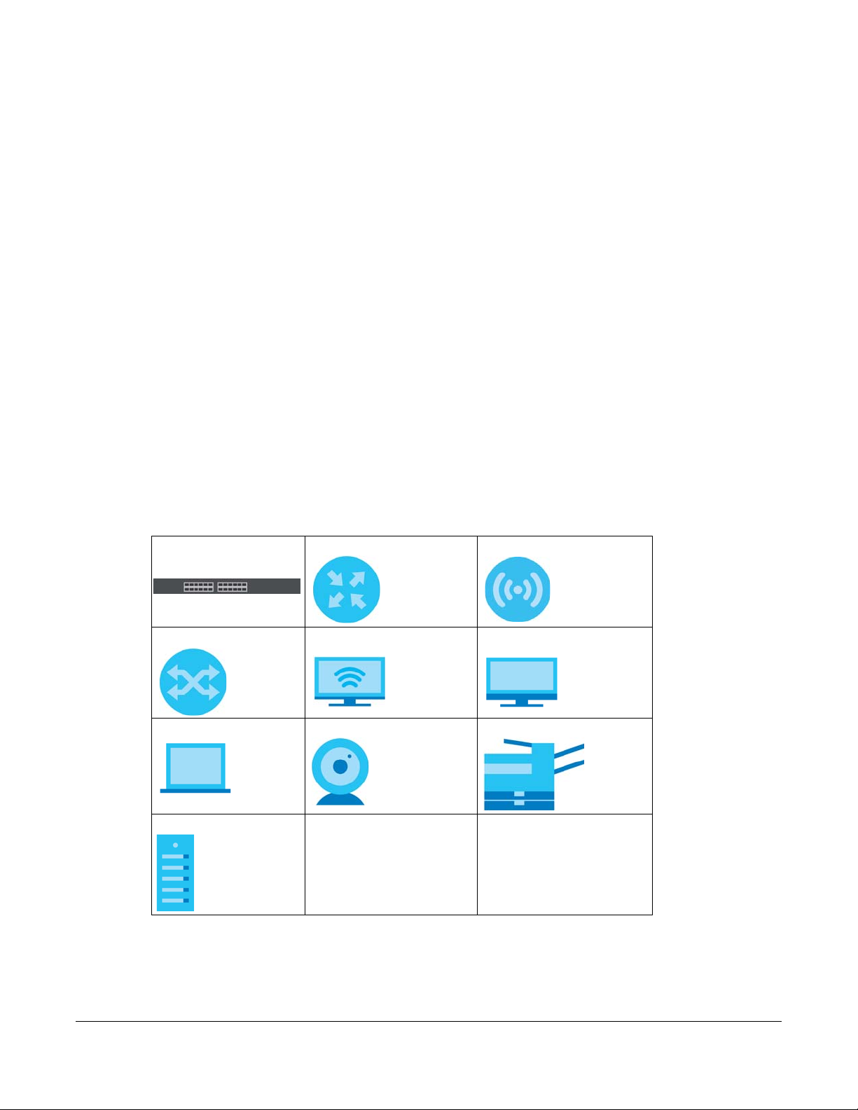
Icons Used in Figures
Figures in this user guide may use the following generic icons. The Switch icon is not an exact
representation of your device.
Switch Generic Router Wireless Router / Access Point
Generic Switch Smart TV Desktop
Laptop IP Camera Printer
Server
XGS2220 Series User’s Guide
3

Contents Overview
Contents Overview
User’s Guide ......................................................................................................................................27
Getting to Know Your Switch .............................................................................................................. 28
Hardware Installation and Connection ............................................................................................. 40
Hardware Panels .................................................................................................................................. 44
Technical Reference ........................................................................................................................56
Web Configurator ................................................................................................................................. 57
Initial Setup Example .......................................................................................................................... 100
Tutorials ................................................................................................................................................ 105
DASHBOARD ........................................................................................................................................ 117
MONITOR ............................................................................................................................................. 122
ARP Table ............................................................................................................................................ 123
IP Table ................................................................................................................................................. 125
IPv6 Neighbor Table ........................................................................................................................... 127
MAC Table ........................................................................................................................................... 129
Neighbor ............................................................................................................................................. 132
Path MTU Table ................................................................................................................................... 136
Port Status ............................................................................................................................................ 137
Routing Table ...................................................................................................................................... 145
System Information ............................................................................................................................. 147
System Log .......................................................................................................................................... 150
SYSTEM ................................................................................................................................................. 152
Cloud Management .......................................................................................................................... 153
General Setup ..................................................................................................................................... 157
Interface Setup ................................................................................................................................... 161
IP Setup ................................................................................................................................................ 163
IPv6 ....................................................................................................................................................... 170
Logins ................................................................................................................................................... 187
SNMP .................................................................................................................................................... 189
Switch Setup ........................................................................................................................................ 198
Syslog Setup ........................................................................................................................................ 201
Time Range ......................................................................................................................................... 204
PORT ..................................................................................................................................................... 207
Auto PD Recovery .............................................................................................................................. 208
Flex Link ................................................................................................................................................ 213
Green Ethernet ................................................................................................................................... 216
Link Aggregation ................................................................................................................................ 218
Link Layer Discovery Protocol (LLDP) ................................................................................................ 226
XGS2220 Series User’s Guide
4

Contents Overview
OAM ..................................................................................................................................................... 248
PoE Setup ............................................................................................................................................. 256
Port Setup ............................................................................................................................................ 264
ZULD ...................................................................................................................................................... 266
SWITCHING .......................................................................................................................................... 270
Layer 2 Protocol Tunneling ................................................................................................................ 271
Loop Guard ......................................................................................................................................... 275
MAC Pinning ....................................................................................................................................... 278
Mirroring ............................................................................................................................................... 280
Multicast .............................................................................................................................................. 282
Static Multicast Forwarding ............................................................................................................... 310
PPPoE ................................................................................................................................................... 315
Differentiated Services ....................................................................................................................... 323
Queuing Method ................................................................................................................................ 327
Priority Queue ..................................................................................................................................... 330
Bandwidth Control ............................................................................................................................. 332
sFlow ..................................................................................................................................................... 334
Spanning Tree Protocol ...................................................................................................................... 338
Static MAC Filtering ............................................................................................................................ 362
Static MAC Forwarding ...................................................................................................................... 364
VLAN .................................................................................................................................................... 366
VLAN Isolation ..................................................................................................................................... 390
VLAN Mapping ................................................................................................................................... 393
VLAN Stacking .................................................................................................................................... 397
NETWORKING ...................................................................................................................................... 404
ARP Setup ............................................................................................................................................ 405
DHCP .................................................................................................................................................... 411
Static Route ......................................................................................................................................... 424
SECURITY .............................................................................................................................................. 428
AAA ...................................................................................................................................................... 429
Access Control .................................................................................................................................... 443
Classifier ............................................................................................................................................... 453
Policy Rule ........................................................................................................................................... 462
Anti-Arpscan ....................................................................................................................................... 468
BPDU Guard ........................................................................................................................................ 474
Storm Control ...................................................................................................................................... 477
Error-Disable ........................................................................................................................................ 479
IP Source Guard .................................................................................................................................. 485
DHCP Snooping .................................................................................................................................. 489
ARP Inspection .................................................................................................................................... 500
Port Authentication ............................................................................................................................ 518
Port Security ......................................................................................................................................... 530
MAINTENANCE .................................................................................................................................... 533
XGS2220 Series User’s Guide
5

Contents Overview
Networked AV Mode ......................................................................................................................... 556
Troubleshooting and Appendices .................................................................................................616
Troubleshooting .................................................................................................................................. 617
XGS2220 Series User’s Guide
6

Table of Contents
Table of Contents
Document Conventions .................................................................. ....................................................3
Contents Overview..............................................................................................................................4
Table of Contents.................................................................................................................................7
Part I: User’s Guide.......................................................................................... 27
Chapter 1
Getting to Know Your Switch ............................................................................................................28
1.1 Introduction ..................................................................................................................................... 28
1.1.1 Multi-Gigabit .......................................................................................................................... 29
1.1.2 Management Modes ........................................................................................................... 30
1.1.3 Mode Changing ................................................................................................................... 31
1.1.4 ZON Utility ............................................................................................................................... 33
1.1.5 Web Configurator Networked AV Mode ........................................................................... 34
1.1.6 PoE .......................................................................................................................................... 34
1.2 Example Applications .................................................................................................................... 35
1.2.1 PoE Example Application ..................................................................................................... 35
1.2.2 Backbone Example Application ......................................................................................... 36
1.2.3 Bridging Example Application .............................................................................................36
1.2.4 High Performance Switching Example ............................................................................... 37
1.2.5 IEEE 802.1Q VLAN Application Examples ........................................................................... 37
1.2.6 IPv6 Support ........................................................................................................................... 38
1.3 Ways to Manage the Switch ......................................................................................................... 38
1.4 Good Habits for Managing the Switch ........................................................................................39
Chapter 2
Hardware Installation and Connection ...........................................................................................40
2.1 Installation Scenarios ...................................................................................................................... 40
2.2 Safety Precautions .......................................................................................................................... 40
2.3 Freestanding Installation Procedure ............................................................................................ 40
2.4 Mounting the Switch on a Rack ................................................................................................... 41
2.4.1 Installation Requirements ..................................................................................................... 41
2.4.2 Precautions ............................................................................................................................ 41
2.4.3 Attaching the Mounting Brackets to the Switch ............................................................... 42
2.4.4 Mounting the Switch on a Rack .......................................................................................... 42
XGS2220 Series User’s Guide
7

Table of Contents
Chapter 3
Hardware Panels................................................................................................................................44
3.1 Front Panel Connections ............................................................................................................... 44
3.1.1 Gigabit Ethernet Ports ........................................................................................................... 45
3.1.2 SFP/SFP+ Slots ......................................................................................................................... 46
3.1.3 Console Port .......................................................................................................................... 48
3.2 Rear Panel ....................................................................................................................................... 48
3.2.1 Grounding .............................................................................................................................. 49
3.2.2 AC Power Connection ......................................................................................................... 51
3.3 LEDs .................................................................................................................................................. 53
Part II: Technical Reference........................................................................... 56
Chapter 4
Web Configurator...............................................................................................................................57
4.1 Overview ......................................................................................................................................... 57
4.2 System Login .................................................................................................................................... 57
4.3 Zyxel One Network (ZON) Utility .................................................................................................... 62
4.3.1 Requirements ......................................................................................................................... 62
4.3.2 Run the ZON Utility ................................................................................................................. 62
4.4 Networked AV Mode Wizard ........................................................................................................ 66
4.4.1 Basic Settings ......................................................................................................................... 66
4.4.2 Advanced Settings ............................................................................................................... 71
4.5 Wizard .............................................................................................................................................. 76
4.5.1 Basic ....................................................................................................................................... 77
4.5.2 Protection .............................................................................................................................. 82
4.5.3 VLAN ....................................................................................................................................... 84
4.5.4 QoS ......................................................................................................................................... 85
4.6 Web Configurator Layout .............................................................................................................. 86
4.6.1 Tables and Lists ...................................................................................................................... 95
4.6.2 Change Your Password ........................................................................................................ 96
4.7 Save Your Configuration ................................................................................................................ 97
4.8 Switch Lockout ................................................................................................................................ 97
4.9 Reset the Switch ............................................................................................................................. 97
4.9.1 Reboot the Switch ................................................................................................................ 97
4.9.2 Reload the Configuration File .............................................................................................. 98
4.10 Log Out of the Web Configurator .............................................................................................. 98
4.11 Help ................................................................................................................................................ 99
Chapter 5
Initial Setup Example.......................................................................................................................100
XGS2220 Series User’s Guide
8

Table of Contents
5.1 Overview ....................................................................................................................................... 100
5.1.1 Create a VLAN .................................................................................................................... 100
5.1.2 Set Port VID .......................................................................................................................... 101
5.1.3 Configure Switch Management IP Address ..................................................................... 102
Chapter 6
Tutorials.............................................................................................................................................105
6.1 Overview ....................................................................................................................................... 105
6.2 How to Use DHCPv4 Snooping on the Switch ........................................................................... 105
6.3 How to Use DHCPv4 Relay on the Switch .................................................................................. 109
6.3.1 DHCP Relay Tutorial Introduction ...................................................................................... 109
6.3.2 Create a VLAN .................................................................................................................... 109
6.3.3 Configure DHCPv4 Relay ...................................................................................................112
6.3.4 Troubleshooting ................................................................................................................... 113
6.4 How to Use Auto Configuration through a DHCP Server on the Switch ................................ 113
Chapter 7
DASHBOARD .....................................................................................................................................117
7.1 New User Interface ....................................................................................................................... 117
7.2 DASHBOARD .................................................................................................................................. 117
7.2.1 Port Status ............................................................................................................................ 120
7.2.2 Quick Links to Use ................................................................................................................ 120
Chapter 8
MONITOR...........................................................................................................................................122
Chapter 9
ARP Table..........................................................................................................................................123
9.1 ARP Table Overview ..................................................................................................................... 123
9.1.1 What You Can Do ............................................................................................................... 123
9.1.2 What You Need to Know ................................................................................................... 123
9.2 Viewing the ARP Table ................................................................................................................. 123
Chapter 10
IP Table..............................................................................................................................................125
10.1 IP Table Overview ....................................................................................................................... 125
10.2 Viewing the IP Table ................................................................................................................... 126
Chapter 11
IPv6 Neighbor Table.........................................................................................................................127
11.1 IPv6 Neighbor Table Overview .................................................................................................. 127
11.2 Viewing the IPv6 Neighbor Table ............................................................................................. 127
XGS2220 Series User’s Guide
9

Table of Contents
Chapter 12
MAC Table........................................................................................................................................129
12.1 MAC Table Overview ................................................................................................................. 129
12.1.1 What You Can Do ............................................................................................................. 129
12.1.2 What You Need to Know ................................................................................................. 129
12.2 Viewing the MAC Table ............................................................................................................. 130
Chapter 13
Neighbor ..........................................................................................................................................132
13.1 Neighbor Overview .................................................................................................................... 132
13.1.1 What You Can Do ............................................................................................................. 132
13.2 Neighbor ...................................................................................................................................... 132
13.2.1 Neighbor Details ................................................................................................................ 133
Chapter 14
Path MTU Table.................................................................................................................................136
14.1 Path MTU Overview .................................................................................................................... 136
14.2 Viewing the Path MTU Table ..................................................................................................... 136
Chapter 15
Port Status .........................................................................................................................................137
15.0.1 What You Can Do ............................................................................................................. 137
15.1 Port Status .................................................................................................................................... 137
15.1.1 Port Details ......................................................................................................................... 138
15.2 DDMI ............................................................................................................................................ 141
15.2.1 DDMI Details ...................................................................................................................... 141
15.3 Port Utilization .............................................................................................................................. 143
Chapter 16
Routing Table....................................................................................................................................145
16.1 Routing Table Overview ............................................................................................................ 145
16.1.1 What You Can Do ............................................................................................................. 145
16.2 IPv4 Routing Table ...................................................................................................................... 145
16.3 IPv6 Routing Table ...................................................................................................................... 146
Chapter 17
System Information..........................................................................................................................147
17.0.1 What You Can Do ............................................................................................................. 147
17.1 System Information ..................................................................................................................... 147
Chapter 18
System Log........................................................................................................................................150
18.1 System Log Overview ................................................................................................................. 150
XGS2220 Series User’s Guide
10

Table of Contents
18.2 System Log .................................................................................................................................. 150
Chapter 19
SYSTEM ..............................................................................................................................................152
Chapter 20
Cloud Management........................................................................................................................153
20.1 Cloud Management Overview ................................................................................................ 153
20.2 Nebula Center Control Discovery ............................................................................................ 153
Chapter 21
General Setup................... ............................................ .... .... ... ........................................................157
21.1 General Setup ............................................................................................................................. 157
21.2 Hardware Monitor Setup ........................................................................................................... 159
Chapter 22
Interface Setup.................................................................................................................................161
22.1 Interface Setup Overview ......................................................................................................... 161
22.2 Interface Setup ........................................................................................................................... 161
22.2.1 Add/Edit Interfaces ........................................................................................................... 162
Chapter 23
IP Setup .............................................................................................................................................163
23.1 IP Setup Overview ...................................................................................................................... 163
23.1.1 What You Can Do ............................................................................................................. 163
23.1.2 IP Interfaces ....................................................................................................................... 163
23.2 IP Status ........................................................................................................................................ 164
23.2.1 IP Status Details .................................................................................................................. 164
23.3 IP Setup ........................................................................................................................................ 166
23.3.1 Add/Edit IP Interfaces ....................................................................................................... 167
23.4 Network Proxy Configuration .................................................................................................... 168
Chapter 24
IPv6....................................................................................................................................................170
24.1 IPv6 Overview ............................................................................................................................. 170
24.1.1 What You Can Do ............................................................................................................. 170
24.2 IPv6 Status .................................................................................................................................... 170
24.2.1 IPv6 Interface Status Details ............................................................................................. 171
24.3 IPv6 Global Setup ....................................................................................................................... 173
24.4 IPv6 Interface Setup ................................................................................................................... 174
24.4.1 Edit an IPv6 Interface ........................................................................................................ 175
24.5 IPv6 Link-Local Address Setup ................................................................................................... 175
24.5.1 Edit an IPv6 Link-Local Address ........................................................................................ 176
24.6 IPv6 Global Address Setup ........................................................................................................ 177
XGS2220 Series User’s Guide
11

Table of Contents
24.6.1 Add/Edit an IPv6 Global Address .................................................................................... 178
24.7 IPv6 Neighbor Discovery Setup ................................................................................................. 178
24.7.1 Edit an IPv6 Neighbor Discovery ..................................................................................... 179
24.8 IPv6 Router Discovery Setup ...................................................................................................... 180
24.8.1 Edit IPv6 Router Discovery ................................................................................................ 181
24.9 IPv6 Prefix Setup .......................................................................................................................... 182
24.9.1 Add/Edit IPv6 Prefix ........................................................................................................... 182
24.10 IPv6 Neighbor Setup ................................................................................................................. 183
24.10.1 Add/Edit IPv6 Neighbor .................................................................................................. 184
24.11 DHCPv6 Client Setup ................................................................................................................ 184
24.11.1 Edit DHCPv6 Client .......................................................................................................... 185
Chapter 25
Logins................................................................................................................................................187
25.1 Set Up Login Accounts ............................................................................................................... 187
Chapter 26
SNMP .................................................................................................................................................189
26.1 SNMP Overview .......................................................................................................................... 189
26.1.1 What You Can Do ............................................................................................................. 189
26.2 Configure SNMP .......................................................................................................................... 189
26.3 Configure SNMP User ................................................................................................................. 191
26.3.1 Add/Edit SNMP User .......................................................................................................... 191
26.4 Configure SNMP Trap Group ..................................................................................................... 193
26.5 Enable or Disable Sending of SNMP Traps on a Port .............................................................. 194
26.6 Technical Reference .................................................................................................................. 194
26.6.1 About SNMP ....................................................................................................................... 195
Chapter 27
Switch Setup....................................................... .... .... ............................................ .... ......................198
27.1 Switch Setup Overview .............................................................................................................. 198
27.1.1 Introduction to VLANs ....................................................................................................... 198
27.2 Switch Setup ................................................................................................................................ 198
Chapter 28
Syslog Setup .....................................................................................................................................201
28.1 Syslog Overview .......................................................................................................................... 201
28.1.1 What You Can Do ............................................................................................................. 201
28.2 Syslog Setup ................................................................................................................................ 201
28.2.1 Add/Edit a Syslog Server .................................................................................................. 203
Chapter 29
Time Range.......................................................................................................................................204
XGS2220 Series User’s Guide
12

Table of Contents
29.1 Time Range Overview ................................................................................................................ 204
29.1.1 What You Can Do ............................................................................................................. 204
29.2 Configuring Time Range ............................................................................................................ 204
29.2.1 Add/Edit Time Range ....................................................................................................... 205
Chapter 30
PORT ..................................................................................................................................................207
Chapter 31
Auto PD Recovery............. .... .... ... ............................................ .... .... ... .............................................208
31.1 Auto PD Recovery (for PoE models only) Overview ............................................................... 208
31.1.1 What You Can Do ............................................................................................................. 208
31.2 Auto PD Recovery ...................................................................................................................... 208
31.2.1 Activate the Automatic PD Recovery ............................................................................ 210
Chapter 32
Flex Link ............................................ .... ... .... ............................................ .... ... .... ..............................213
32.1 Flex Link Overview ...................................................................................................................... 213
32.1.1 What You Can Do ............................................................................................................. 213
32.2 Flex Link Status ............................................................................................................................. 213
32.3 Flex Link Setup ............................................................................................................................. 214
32.3.1 Add/Edit Flex Link .............................................................................................................. 215
Chapter 33
Green Ethernet.................................................................. .... ...........................................................216
33.1 Green Ethernet Overview .......................................................................................................... 216
33.2 Configuring Green Ethernet ...................................................................................................... 216
Chapter 34
Link Aggregation .................................... .... .... ... ............................................ .... .... ..........................218
34.1 Link Aggregation Overview ....................................................................................................... 218
34.1.1 What You Can Do ............................................................................................................. 218
34.1.2 What You Need to Know ................................................................................................. 218
34.2 Link Aggregation Status ............................................................................................................. 219
34.3 Link Aggregation Setting ........................................................................................................... 221
34.4 Link Aggregation Control Protocol ........................................................................................... 222
34.5 Technical Reference .................................................................................................................. 224
34.5.1 Static Trunking Example ................................................................................................... 224
Chapter 35
Link Layer Discovery Protocol (LLDP) .............................................................................................226
35.1 LLDP Overview ............................................................................................................................ 226
35.2 LLDP-MED Overview ................................................................................................................... 227
35.2.1 What You Can Do – LLDP ................................................................................................. 228
XGS2220 Series User’s Guide
13

Table of Contents
35.2.2 What You Can Do – LLDP MED ........................................................................................ 228
35.3 LLDP Local Status ........................................................................................................................ 228
35.3.1 LLDP Local Port Status Detail ...........................................................................................230
35.4 LLDP Remote Status .................................................................................................................... 233
35.4.1 LLDP Remote Port Status Detail ....................................................................................... 234
35.5 LLDP Setup ................................................................................................................................... 238
35.6 Basic TLV Setting ......................................................................................................................... 240
35.7 Org-specific TLV Setting ............................................................................................................. 241
35.8 LLDP-MED Setup .......................................................................................................................... 242
35.9 LLDP-MED Network Policy .......................................................................................................... 243
35.9.1 Add/Edit LLDP-MED Network Policy ................................................................................ 244
35.10 LLDP-MED Location .................................................................................................................. 245
35.10.1 Add/Edit LLDP-MED Location ........................................................................................ 245
Chapter 36
OAM..................................................................................................................................................248
36.1 OAM Overview ........................................................................................................................... 248
36.1.1 What You Can Do ............................................................................................................. 248
36.2 OAM Status .................................................................................................................................. 248
36.2.1 OAM Details ....................................................................................................................... 249
36.3 OAM Setup .................................................................................................................................. 253
36.4 OAM Remote Loopback ........................................................................................................... 254
Chapter 37
PoE Setup..........................................................................................................................................256
37.1 PoE Status (for PoE models only) ............................................................................................... 256
37.2 PoE Setup ..................................................................................................................................... 258
37.3 PoE Time Range Setup ............................................................................................................... 262
37.3.1 Add/Edit PoE Time Range ................................................................................................ 262
Chapter 38
Port Setup..........................................................................................................................................264
38.1 Port Setup .................................................................................................................................... 264
Chapter 39
ZULD...................................................................................................................................................266
39.1 ZULD Overview ............................................................................................................................ 266
39.1.1 What You Can Do ............................................................................................................. 266
39.1.2 What You Need to Know ................................................................................................. 266
39.2 ZULD Status .................................................................................................................................. 267
39.3 ZULD Setup ................................................................................................................................... 268
Chapter 40
SWITCHING........................................................................................................................................270
XGS2220 Series User’s Guide
14

Table of Contents
Chapter 41
Layer 2 Protocol Tunneling..............................................................................................................271
41.1 Layer 2 Protocol Tunneling Overview .......................................................................................271
41.1.1 What You Can Do ............................................................................................................. 271
41.1.2 What You Need to Know ................................................................................................. 271
41.2 Configuring Layer 2 Protocol Tunneling ................................................................................... 272
Chapter 42
Loop Guard ......................................................................................................................................275
42.1 Loop Guard Overview ............................................................................................................... 275
42.1.1 What You Can Do ............................................................................................................. 275
42.1.2 What You Need to Know ................................................................................................. 275
42.2 Loop Guard Setup ...................................................................................................................... 277
Chapter 43
MAC Pinning.....................................................................................................................................278
43.1 MAC Pinning Overview .............................................................................................................. 278
43.2 MAC Pinning Configuration ...................................................................................................... 278
Chapter 44
Mirroring............................................................................................................................................280
44.1 Mirroring Overview ..................................................................................................................... 280
44.1.1 What You Need to Know ................................................................................................. 280
44.2 Local Port Mirroring ..................................................................................................................... 280
Chapter 45
Multicast............................................................................................................................................282
45.1 Multicast Overview ..................................................................................................................... 282
45.1.1 What You Can Do – IPv4 Multicast ................................................................................. 282
45.1.2 What You Can Do – IPv6 Multicast ................................................................................. 282
45.1.3 What You Can Do – MVR ................................................................................................. 283
45.1.4 What You Need to Know ................................................................................................. 283
45.2 IPv4 Multicast Status ................................................................................................................... 286
45.3 IGMP Snooping ........................................................................................................................... 287
45.4 IGMP Snooping VLAN ................................................................................................................ 290
45.4.1 Add/Edit IGMP Snooping VLANs ..................................................................................... 291
45.5 IGMP Filtering Profile ................................................................................................................... 292
45.5.1 Add IGMP Filtering Profile ................................................................................................. 293
45.5.2 Add IGMP Filtering Rule .................................................................................................... 293
45.6 IPv6 Multicast Status ................................................................................................................... 294
45.7 MLD Snooping-proxy .................................................................................................................. 295
45.8 MLD Snooping-proxy VLAN ....................................................................................................... 295
45.8.1 Add/Edit MLD Snooping-proxy VLAN ............................................................................. 296
XGS2220 Series User’s Guide
15

Table of Contents
45.9 MLD Snooping-proxy Port Role Setting ..................................................................................... 298
45.10 MLD Snooping-proxy Filtering .................................................................................................. 299
45.11 MLD Snooping-proxy Filtering Profile ...................................................................................... 301
45.11.1 Add MLD Snooping-proxy Filtering Profile .................................................................... 301
45.11.2 Add MLD Snooping-proxy Filtering Rule ....................................................................... 302
45.12 General MVR Configuration .................................................................................................... 303
45.12.1 Add/Edit MVR .................................................................................................................. 304
45.13 MVR Group Setup ..................................................................................................................... 305
45.13.1 Add/Edit MVR Group ...................................................................................................... 306
45.13.2 MVR Configuration Example ......................................................................................... 307
Chapter 46
Static Multicast Forwarding.............................................................................................................310
46.1 Static Multicast Forwarding Overview ..................................................................................... 310
46.1.1 What You Can Do ............................................................................................................. 310
46.1.2 What You Need To Know ................................................................................................. 310
46.2 Static Multicast Forwarding By MAC ........................................................................................311
46.2.1 Add/Edit Static Multicast Forwarding By MAC .............................................................. 312
46.3 Configure a Static Multicast IPv4 Address ............................................................................... 312
46.3.1 Add/Edit a Static Multicast Address By IP ...................................................................... 313
Chapter 47
PPPoE.................................................................................................................................................315
47.1 PPPoE Intermediate Agent Overview ...................................................................................... 315
47.1.1 What You Can Do ............................................................................................................. 315
47.1.2 What You Need to Know ................................................................................................. 315
47.2 PPPoE Intermediate Agent ........................................................................................................ 317
47.3 PPPoE IA Port ............................................................................................................................... 319
47.4 PPPoE IA Port VLAN .................................................................................................................... 320
47.5 PPPoE IA VLAN ............................................................................................................................ 322
Chapter 48
Differentiated Services ....................................................................................................................323
48.1 DiffServ Overview ....................................................................................................................... 323
48.1.1 What You Can Do ............................................................................................................. 323
48.1.2 What You Need to Know ................................................................................................. 323
48.2 Activating DiffServ ...................................................................................................................... 324
48.3 DSCP-to-IEEE 802.1p Priority Settings ......................................................................................... 325
48.3.1 Configuring DSCP Settings ...............................................................................................326
Chapter 49
Queuing Method..............................................................................................................................327
49.1 Queuing Method Overview ...................................................................................................... 327
XGS2220 Series User’s Guide
16

Table of Contents
49.1.1 What You Can Do ............................................................................................................. 327
49.1.2 What You Need to Know ................................................................................................. 327
49.2 Configuring Queuing ................................................................................................................. 328
Chapter 50
Priority Queue...................................................................................................................................330
50.1 Priority Queue Overview ............................................................................................................ 330
50.1.1 What You Can Do ............................................................................................................. 330
50.2 Assign Priority Queue .................................................................................................................. 330
Chapter 51
Bandwidth Control...........................................................................................................................332
51.1 Bandwidth Control Overview .................................................................................................... 332
51.1.1 What You Can Do ............................................................................................................. 332
51.1.2 CIR and PIR ........................................................................................................................ 332
51.2 Bandwidth Control Setup .......................................................................................................... 332
Chapter 52
sFlow..................................................................................................................................................334
52.1 sFlow Overview ........................................................................................................................... 334
52.2 sFlow Port Configuration ............................................................................................................ 334
52.3 sFlow Collector Configuration ................................................................................................... 336
52.3.1 Add/Edit sFlow Collector .................................................................................................. 336
Chapter 53
Spanning Tree Protocol ...................................................................................................................338
53.1 Spanning Tree Protocol Overview ............................................................................................ 338
53.1.1 What You Can Do ............................................................................................................. 338
53.1.2 What You Need to Know ................................................................................................. 338
53.2 Spanning Tree Protocol Status .................................................................................................. 341
53.3 Spanning Tree Setup .................................................................................................................. 341
53.4 Rapid Spanning Tree Protocol Status .......................................................................................344
53.5 Configure Rapid Spanning Tree Protocol ................................................................................ 346
53.6 Multiple Rapid Spanning Tree Protocol Status ........................................................................ 348
53.7 Configure Multiple Rapid Spanning Tree Protocol ................................................................. 350
53.8 Multiple Spanning Tree Protocol Status ....................................................................................353
53.9 Configure Multiple Spanning Tree Protocol ............................................................................ 355
53.9.1 Add/Edit Multiple Spanning Tree .................................................................................... 357
53.10 Multiple Spanning Tree Protocol Port Setup .......................................................................... 358
53.11 Technical Reference ................................................................................................................ 359
53.11.1 MSTP Network Example .................................................................................................. 360
53.11.2 MST Region ....................................................................................................................... 360
53.11.3 MST Instance .................................................................................................................... 361
XGS2220 Series User’s Guide
17

Table of Contents
53.11.4 Common and Internal Spanning Tree (CIST) ............................................................... 361
Chapter 54
Static MAC Filtering..........................................................................................................................362
54.1 Static MAC Filtering Overview .................................................................................................. 362
54.1.1 What You Can Do ............................................................................................................. 362
54.2 Configure a Static MAC Filtering Rule ...................................................................................... 362
54.2.1 Add/Edit a Static MAC Filtering Rule .............................................................................. 363
Chapter 55
Static MAC Forwarding....................................................................................................................364
55.1 Static MAC Forwarding Overview ............................................................................................364
55.1.1 What You Can Do ............................................................................................................. 364
55.2 Configure Static MAC Forwarding ...........................................................................................364
55.2.1 Add/Edit Static MAC Forwarding Rules .......................................................................... 365
Chapter 56
VLAN..................................................................................................................................................366
56.1 VLAN Overview ........................................................................................................................... 366
56.1.1 What You Can Do ............................................................................................................. 366
56.1.2 What You Need to Know ................................................................................................. 366
56.2 Introduction to IEEE 802.1Q Tagged VLANs ............................................................................. 367
56.3 VLAN Status ................................................................................................................................. 369
56.3.1 VLAN Details ...................................................................................................................... 370
56.4 Configure a Static VLAN ............................................................................................................ 371
56.4.1 Add/Edit a Static VLAN .................................................................................................... 372
56.5 VLAN Port Setup .......................................................................................................................... 373
56.6 Configure GVRP .......................................................................................................................... 375
56.7 Subnet Based VLANs .................................................................................................................. 376
56.8 Configuring Subnet Based VLAN .............................................................................................. 377
56.8.1 Add/Edit Subnet Based VLAN ......................................................................................... 377
56.9 Protocol Based VLANs ................................................................................................................ 378
56.10 Configuring Protocol Based VLAN ..........................................................................................379
56.10.1 Add/Edit a Protocol Based VLAN .................................................................................. 380
56.11 Voice VLAN ............................................................................................................................... 381
56.11.1 Add/Edit a Voice VLAN ..................................................................................................382
56.12 MAC Based VLAN ..................................................................................................................... 383
56.12.1 Add/Edit a MAC Based VLAN ....................................................................................... 384
56.13 Vendor ID Based VLAN ............................................................................................................ 385
56.13.1 Add/Edit a Vendor ID Based VLAN ............................................................................... 385
56.14 Port-Based VLAN Setup ............................................................................................................ 386
56.15 Configure a Port-Based VLAN ................................................................................................. 387
XGS2220 Series User’s Guide
18

Table of Contents
Chapter 57
VLAN Isolation..................................................................................................................................390
57.1 VLAN Isolation Overview ............................................................................................................ 390
57.2 Configuring VLAN Isolation ........................................................................................................ 390
57.2.1 Add/Edit a VLAN Isolation Rule ....................................................................................... 391
Chapter 58
VLAN Mapping.................................................................................................................................393
58.1 VLAN Mapping Overview .......................................................................................................... 393
58.1.1 VLAN Mapping Example .................................................................................................. 393
58.1.2 What You Can Do ............................................................................................................. 393
58.2 Enable VLAN Mapping .............................................................................................................. 394
58.3 VLAN Mapping Setup ................................................................................................................ 395
58.3.1 Add/Edit VLAN Mapping ................................................................................................. 395
Chapter 59
VLAN Stacking..................................................................................................................................397
59.1 VLAN Stacking Overview ........................................................................................................... 397
59.1.1 VLAN Stacking Example ...................................................................................................397
59.2 VLAN Stacking Port Roles ........................................................................................................... 398
59.3 VLAN Tag Format ........................................................................................................................ 398
59.3.1 Frame Format .................................................................................................................... 399
59.4 Configuring VLAN Stacking ....................................................................................................... 399
59.5 Port-Based Q-in-Q ....................................................................................................................... 401
59.6 Selective Q-in-Q .......................................................................................................................... 402
59.6.1 Add/Edit Selective Q-in-Q ...............................................................................................403
Chapter 60
NETWORKING....................................................................................................................................404
Chapter 61
ARP Setup..........................................................................................................................................405
61.1 ARP Overview ............................................................................................................................. 405
61.1.1 What You Can Do ............................................................................................................. 405
61.1.2 What You Need to Know ................................................................................................. 405
61.2 ARP Learning ............................................................................................................................... 407
61.3 Static ARP .................................................................................................................................... 408
61.3.1 Add/Edit Static ARP .......................................................................................................... 409
Chapter 62
DHCP .................................................................................................................................................411
62.1 DHCP Overview .......................................................................................................................... 411
62.1.1 What You Can Do ............................................................................................................. 411
XGS2220 Series User’s Guide
19

Table of Contents
62.1.2 What You Need to Know ................................................................................................. 411
62.2 DHCPv4 Relay Status .................................................................................................................. 412
62.3 DHCPv4 Option 82 Profile .......................................................................................................... 412
62.3.1 Add/Edit a DHCPv4 Option 82 Profile ............................................................................. 413
62.4 Configuring DHCPv4 Smart Relay ............................................................................................. 414
62.4.1 Add/Edit DHCPv4 Global Relay Port .............................................................................. 416
62.4.2 DHCP Smart Relay Configuration Example .................................................................... 416
62.5 DHCPv4 VLAN Setting ................................................................................................................ 418
62.5.1 Add/Edit DHCPv4 VLAN Setting ...................................................................................... 419
62.5.2 Add/Edit DHCPv4 VLAN Port ........................................................................................... 419
62.6 DHCPv6 Relay ............................................................................................................................. 420
62.6.1 Add/Edit DHCPv6 Relay ...................................................................................................421
62.7 DHCP Server Guard .................................................................................................................... 422
Chapter 63
Static Route.......................................................................................................................................424
63.1 Static Routing Overview ............................................................................................................ 424
63.1.1 What You Can Do ............................................................................................................. 424
63.2 IPv4 Static Route ......................................................................................................................... 425
63.2.1 Add/Edit IPv4 Static Route ............................................................................................... 425
63.3 IPv6 Static Route ......................................................................................................................... 426
63.3.1 Add/Edit IPv6 Static Route ............................................................................................... 427
Chapter 64
SECURITY ...........................................................................................................................................428
Chapter 65
AAA...................................................................................................................................................429
65.1 Authentication, Authorization and Accounting (AAA) ......................................................... 429
65.1.1 What You Can Do ............................................................................................................. 429
65.1.2 What You Need to Know ................................................................................................. 429
65.2 RADIUS Server Setup ................................................................................................................... 430
65.3 TACACS+ Server Setup ............................................................................................................... 432
65.4 AAA Setup ................................................................................................................................... 434
65.5 Technical Reference .................................................................................................................. 437
65.5.1 Vendor Specific Attribute ................................................................................................ 437
65.5.2 Supported RADIUS Attributes ........................................................................................... 439
65.5.3 Attributes Used for Authentication .................................................................................. 439
65.5.4 Attributes Used for Accounting ....................................................................................... 440
Chapter 66
Access Control.................................................................................................................................443
66.1 Access Control Overview .......................................................................................................... 443
66.1.1 What You Can Do ............................................................................................................. 443
XGS2220 Series User’s Guide
20

Table of Contents
66.2 Service Access Control .............................................................................................................. 443
66.3 Remote Management ............................................................................................................... 444
66.4 Account Security ........................................................................................................................ 445
66.5 Technical Reference .................................................................................................................. 447
66.5.1 SSH Overview ..................................................................................................................... 447
66.5.2 Introduction to HTTPS ........................................................................................................ 449
66.5.3 Google Chrome Warning Messages .............................................................................. 451
Chapter 67
Classifier............................................................................................................................................453
67.1 Classifier Overview ..................................................................................................................... 453
67.1.1 What You Can Do ............................................................................................................. 453
67.1.2 What You Need to Know ................................................................................................. 453
67.2 Classifier Status ............................................................................................................................ 454
67.3 Classifier Setup ............................................................................................................................ 454
67.3.1 Add/Edit a Classifier .......................................................................................................... 456
67.4 Classifier Global Setting ............................................................................................................. 459
67.5 Classifier Example ....................................................................................................................... 460
Chapter 68
Policy Rule ........................................................................................................................................462
68.1 Policy Rules Overview ................................................................................................................ 462
68.1.1 What You Can Do ............................................................................................................. 462
68.1.2 DiffServ ................................................................................................................................ 462
68.1.3 DSCP and Per-Hop Behavior ........................................................................................... 462
68.2 Policy Rules .................................................................................................................................. 463
68.2.1 Add/Edit a Policy Rule ...................................................................................................... 463
68.3 Policy Example ............................................................................................................................ 466
Chapter 69
Anti-Arpscan ....................................................................................................................................468
69.1 Anti-Arpscan Overview .............................................................................................................. 468
69.1.1 What You Can Do ............................................................................................................. 468
69.1.2 What You Need to Know ................................................................................................. 468
69.2 Anti-Arpscan Status .................................................................................................................... 469
69.3 Anti-Arpscan Host Status ............................................................................................................ 469
69.4 Anti-Arpscan Setup .................................................................................................................... 470
69.5 Anti-Arpscan Trust Host .............................................................................................................. 472
69.5.1 Add/Edit Anti-Arpscan Trust Hosts ................................................................................... 472
Chapter 70
BPDU Guard......................................................................................................................................474
70.1 BPDU Guard Overview ............................................................................................................... 474
XGS2220 Series User’s Guide
21

Table of Contents
70.2 BPDU Guard Status ..................................................................................................................... 474
70.3 BPDU Guard Setup ..................................................................................................................... 475
Chapter 71
Storm Control....................................................................................................................................477
71.1 Storm Control Overview ............................................................................................................. 477
71.1.1 What You Can Do ............................................................................................................. 477
71.2 Storm Control Setup ................................................................................................................... 477
Chapter 72
Error-Disable.....................................................................................................................................479
72.1 Error-Disable Overview ............................................................................................................... 479
72.1.1 CPU Protection Overview ................................................................................................ 479
72.1.2 Error-Disable Recovery Overview .................................................................................... 479
72.1.3 What You Can Do ............................................................................................................. 479
72.2 Error-Disable Status ..................................................................................................................... 480
72.3 CPU Protection Setup ................................................................................................................. 481
72.4 Error-Disable Detect Setup ........................................................................................................ 482
72.5 Error-Disable Recovery Setup .................................................................................................... 483
Chapter 73
IP Source Guard...............................................................................................................................485
73.1 IP Source Guard Overview ........................................................................................................ 485
73.1.1 What You Can Do ............................................................................................................. 485
73.1.2 What You Need to Know ................................................................................................. 485
73.2 IPv4 Source Guard ...................................................................................................................... 486
73.3 IPv4 Source Guard Static Binding ............................................................................................. 486
73.3.1 Add/Edit IPv4 Source Guard Static Binding ................................................................... 488
Chapter 74
DHCP Snooping................................................................................................................................489
74.1 DHCP Snooping Overview ......................................................................................................... 489
74.1.1 What You Can Do ............................................................................................................. 489
74.2 DHCP Snooping Status ............................................................................................................... 489
74.3 DHCP Snooping Setup ............................................................................................................... 492
74.4 DHCP Snooping Port Setup ....................................................................................................... 493
74.5 DHCP Snooping VLAN Setup ..................................................................................................... 495
74.6 DHCP Snooping VLAN Port Setup .............................................................................................496
74.6.1 Add/EDIT DHCP Snooping VLAN Ports ............................................................................ 496
74.7 Technical Reference .................................................................................................................. 497
74.7.1 DHCP Snooping Overview ............................................................................................... 497
Chapter 75
ARP Inspection .................................................................................................................................500
XGS2220 Series User’s Guide
22

Table of Contents
75.1 ARP Inspection Status ................................................................................................................. 500
75.2 ARP Inspection VLAN Status ...................................................................................................... 501
75.3 ARP Inspection Log Status ......................................................................................................... 501
75.4 ARP Inspection Setup ................................................................................................................. 502
75.5 ARP Inspection Port Setup ......................................................................................................... 504
75.6 ARP Inspection VLAN Setup ...................................................................................................... 505
75.7 IPv6 Source Guard ...................................................................................................................... 506
75.8 IPv6 Source Binding Status ......................................................................................................... 507
75.9 IPv6 Static Binding ...................................................................................................................... 508
75.9.1 Add/Edit IPv6 Static Binding ............................................................................................508
75.10 IPv6 Source Guard Policy ........................................................................................................ 509
75.10.1 Add/Edit an IPv6 Source Guard Policy ......................................................................... 510
75.11 IPv6 Source Guard Port Setup ................................................................................................. 511
75.12 IPv6 Snooping Policy Setup ..................................................................................................... 512
75.12.1 Add/Edit a IPv6 Snooping Policy ................................................................................... 512
75.13 IPv6 Snooping VLAN Setup ...................................................................................................... 513
75.13.1 Add/Edit an IPv6 Snooping VLAN ................................................................................. 514
75.14 IPv6 DHCP Trust Setup .............................................................................................................. 514
75.15 Technical Reference ................................................................................................................ 516
75.15.1 ARP Inspection Overview ............................................................................................... 516
Chapter 76
Port Authentication..........................................................................................................................518
76.1 Port Authentication Overview .................................................................................................. 518
76.1.1 What You Can Do ............................................................................................................. 518
76.1.2 What You Need to Know ................................................................................................. 519
76.1.3 MAC Authentication ........................................................................................................ 519
76.2 Activate IEEE 802.1x Security ..................................................................................................... 520
76.3 Activate MAC Authentication .................................................................................................. 521
76.4 Guest VLAN ................................................................................................................................. 523
76.5 Compound Authentication ....................................................................................................... 525
76.6 Technical Reference .................................................................................................................. 526
76.6.1 IEEE 802.1x .......................................................................................................................... 526
76.6.2 RADIUS ................................................................................................................................ 527
76.6.3 EAP (Extensible Authentication Protocol) Authentication ........................................... 528
76.6.4 EAPOL (EAP over LAN) ...................................................................................................... 529
Chapter 77
Port Security......................................................................................................................................530
77.1 Port Security Overview ............................................................................................................... 530
77.2 About Port Security ..................................................................................................................... 530
77.3 Port Security Setup ...................................................................................................................... 530
XGS2220 Series User’s Guide
23

Table of Contents
Chapter 78
MAINTENANCE..................................................................................................................................533
78.1 Overview ..................................................................................................................................... 533
78.1.1 What You Can Do ............................................................................................................. 533
78.2 Certificates .................................................................................................................................. 533
78.2.1 HTTPS Certificates .............................................................................................................. 534
78.3 Technical Reference .................................................................................................................. 535
78.3.1 FTP Command Line ........................................................................................................... 535
78.3.2 Filename Conventions ...................................................................................................... 535
78.3.3 FTP Command Line Procedure ........................................................................................ 536
78.3.4 GUI-based FTP Clients ....................................................................................................... 537
78.3.5 FTP Restrictions ................................................................................................................... 537
78.4 Cluster Management Overview ...............................................................................................537
78.4.1 What You Can Do ............................................................................................................. 538
78.5 Cluster Management Status ..................................................................................................... 538
78.6 Clustering Management Setup ................................................................................................ 539
78.7 Technical Reference .................................................................................................................. 541
78.7.1 Cluster Member Switch Management ........................................................................... 541
78.8 Restore Configuration ................................................................................................................ 543
78.9 Backup Configuration ................................................................................................................ 543
78.10 Auto Configuration .................................................................................................................. 544
78.11 Erase Running-Configuration .................................................................................................. 545
78.12 Save Configuration .................................................................................................................. 546
78.13 Configure Clone ....................................................................................................................... 547
78.14 Diagnostic ................................................................................................................................. 548
78.15 Firmware Upgrade .................................................................................................................... 550
78.16 Reboot System .......................................................................................................................... 552
78.17 Tech-Support ............................................................................................................................. 553
78.17.1 Tech-Support Download ................................................................................................ 554
Chapter 79
Networked AV Mode.......................................................................................................................556
79.1 Overview ..................................................................................................................................... 556
79.2 Help .............................................................................................................................................. 556
79.3 Summary ...................................................................................................................................... 556
79.4 MONITOR ..................................................................................................................................... 558
79.5 What You Can Do ...................................................................................................................... 558
79.6 System Information ..................................................................................................................... 558
79.7 SYSTEM ......................................................................................................................................... 560
79.8 What You Can Do ...................................................................................................................... 560
79.9 Cloud Management .................................................................................................................. 561
79.10 General Setup ........................................................................................................................... 563
79.11 IP Setup ...................................................................................................................................... 565
XGS2220 Series User’s Guide
24

Table of Contents
79.11.1 Add/Edit IP Interfaces ..................................................................................................... 566
79.12 Logins ......................................................................................................................................... 567
79.13 Configure SNMP ........................................................................................................................ 569
79.14 Configure SNMP User ............................................................................................................... 571
79.14.1 Add/Edit SNMP User ........................................................................................................ 572
79.15 Configure SNMP Trap Group ................................................................................................... 573
79.16 Enable or Disable Sending of SNMP Traps on a Port ............................................................ 574
79.17 PORT ........................................................................................................................................... 575
79.18 Link Aggregation ...................................................................................................................... 576
79.18.1 What You Can Do ........................................................................................................... 576
79.19 Link Aggregation Status ........................................................................................................... 576
79.20 Link Aggregation Setting ......................................................................................................... 578
79.21 Link Aggregation Control Protocol ......................................................................................... 579
79.22 PoE Status .................................................................................................................................. 581
79.23 PoE Setup ................................................................................................................................... 583
79.24 Port Setup .................................................................................................................................. 586
79.25 SWITCHING ................................................................................................................................ 588
79.26 Port Mirroring ............................................................................................................................. 588
79.27 Multicast .................................................................................................................................... 589
79.27.1 What You Can Do ........................................................................................................... 589
79.28 IPv4 Multicast Status ................................................................................................................. 589
79.29 IGMP Snooping ......................................................................................................................... 590
79.30 IGMP Snooping VLAN .............................................................................................................. 594
79.30.1 Add/Edit IGMP Snooping VLANs ................................................................................... 595
79.31 IGMP Filtering Profile ................................................................................................................. 596
79.31.1 Add IGMP Filtering Profile ............................................................................................... 597
79.31.2 Add IGMP Filtering Rule .................................................................................................. 597
79.32 VLAN .......................................................................................................................................... 598
79.32.1 What You Can Do ........................................................................................................... 598
79.32.2 What You Need to Know ............................................................................................... 598
79.33 VLAN Status ............................................................................................................................... 601
79.33.1 VLAN Details .................................................................................................................... 602
79.34 Configure a Static VLAN .......................................................................................................... 603
79.34.1 Add/Edit a Static VLAN .................................................................................................. 604
79.35 VLAN Port Setup ........................................................................................................................ 605
79.36 SECURITY .................................................................................................................................... 606
79.37 Access Control .......................................................................................................................... 606
79.37.1 What You Can Do ........................................................................................................... 607
79.38 Service Access Control ............................................................................................................ 607
79.39 Remote Management ............................................................................................................. 608
79.40 Storm Control ............................................................................................................................ 609
79.41 MAINTENANCE .......................................................................................................................... 610
79.42 What You Can Do .................................................................................................................... 611
XGS2220 Series User’s Guide
25

Table of Contents
79.43 Restore Configuration .............................................................................................................. 611
79.44 Backup Configuration .............................................................................................................. 611
79.45 Save Configuration .................................................................................................................. 612
79.46 Firmware Upgrade .................................................................................................................... 613
79.47 Reboot System .......................................................................................................................... 613
79.48 Tech-Support ............................................................................................................................. 614
79.48.1 Tech-Support Download ................................................................................................ 615
Part III: Troubleshooting and Appendices..................................................616
Chapter 80
Troubleshooting................................................................................................................................617
80.1 Power, Hardware Connections, and LEDs ............................................................................... 617
80.2 Switch Access and Login ........................................................................................................... 618
80.3 Switch Configuration .................................................................................................................. 620
Appendix A Customer Support ..................................................................................................... 621
Appendix B Common Services...................................................................................................... 626
Appendix C IPv6.............................................................................................................................. 629
Appendix D Legal Information ...................................................................................................... 638
Index.................................................................................................................................................643
XGS2220 Series User’s Guide
26

PART I
User’s Guide
27

CHAPTER 1
Getting to Know Your Switch
1.1 Introduction
This chapter introduces the main features and applications of the Switch.
The XGS2220 Series consists of the following models:
• XGS2220-30
• XGS2220-30HP
• XGS2220-30F
• XGS2220-54
• XGS2220-54HP
• XGS2220-54FP
References to PoE model in this User's Guide only apply to XGS2220-30HP, XGS2220-54HP, and XGS222054FP.
The Switch is a stackable, layer-3, Gigabit Ethernet (GbE) switch with one power slot for single power
supply. The Switch provides six 10 GbE ports for uplink. By integrating router functions, the Switch
performs wire-speed layer-3 routing in addition to layer-2 switching.
With its built-in Web Configurator, including the Zyxel One Network (ZON) Neighbor Management
feature, viewing, managing and configuring the Switch and its neighboring devices is easy. The Switch
can also be managed through Telnet, any terminal emulator program on the console port, or third-party
SNMP management.
In addition, Zyxel offers a proprietary software program called Zyxel One Network (ZON) Utility, it is a
utility tool that assists you to set up and maintain network devices in a more simple and efficient way.
You can download the ZON Utility at www.zyxel.com and install it on a computer.
All models are referred to as the “Switch” in this guide.
The Switch supports NebulaFlex for hybrid mode which can set the Switch to operate in either
standalone or Nebula cloud management mode. When the Switch is in standalone mode, it can be
configured and managed by the Web Configurator. When the Switch is in Nebula cloud management
mode, it can be managed and provisioned by the Zyxel Nebula Control Center (NCC).
The following table describes the hardware features of the Switch by model.
Table 1 XGS2220 Series Comparison Table
FEATURE XGS2220-30 XGS2220-30HP XGS2220-30F XGS2220-54 XGS2220-54HP XGS2220-54FP
Stacking Mode Yes Yes Yes Yes Yes Yes
10/100/1000 Mbps
Ethernet Ports
24 24 No 48 48 48
XGS2220 Series User’s Guide
28

Chapter 1 Getting to Know Your Switch
Table 1 XGS2220 Series Comparison Table (continued)
FEATURE XGS2220-30 XGS2220-30HP XGS2220-30F XGS2220-54 XGS2220-54HP XGS2220-54FP
10/100/1000 Mbps
PoE Ports
100/1000 Mbps SFP
Interface
1/10 Gbps SFP+
Interface
1000 Mbps / 2.5/5/
10 Gbps Ethernet
Ports
1000 Mbps / 2.5/5/
10 Gbps PoE Ports
Smart FAN 1 (8,500 RPM) 3 (8,500 RPM) 2 (8,500 RPM) 2 (8,500 RPM) 4 (8,500 RPM) 1 (8,500 RPM)
Console Port USB-C USB-C USB-C USB-C USB-C USB-C
No 24 No No 48 48
No No 24 No No No
44 444 4
22 222 2
No 2 No No 2 2
2 (16,000 RPM)
The last four 10G ports can also be used for stacking. Use the four 10G fiber ports. When working in
stacking mode, the Switch can operate together with other Switches of the same model and firmware
version and allows you to remotely manage them from one switch using one single IP address.
This section shows a few examples of using the Switch in various network environments.
1.1.1 Multi-Gigabit
A 10 Gigabit port supports speeds of 10G if the connected device supports 10G and a Cat 6a (up to 100
m) or Cat 6 cable (up to 50 m) is used. The speed drops to 1G if these criteria are not met; it drops to
100M if a Cat 5 cable is used (up to 100 m).
If a network device such as a 5G network card, gaming computer, server, Network Attached Storage
(NAS) or Access Point (AP) only supports 2.5 Gigabit or 5 Gigabit connectivity, then the maximum speed
potential of these devices is never reached.
In addition, at the time of writing, most existing cabling is Cat 5e or Cat 6, further limiting maximum
speed or distance potential.
Multi-Gigabit (IEEE 802.3bz) solves these problems by additionally supporting 2.5 Gigabit and 5 Gigabit
Ethernet connections over Cat 5e and higher Ethernet cables. Multi-Gigabit ports are also backward
compatible with 100 Mbps and 1 Gigabit ports.
XGS2220 Series User’s Guide
29
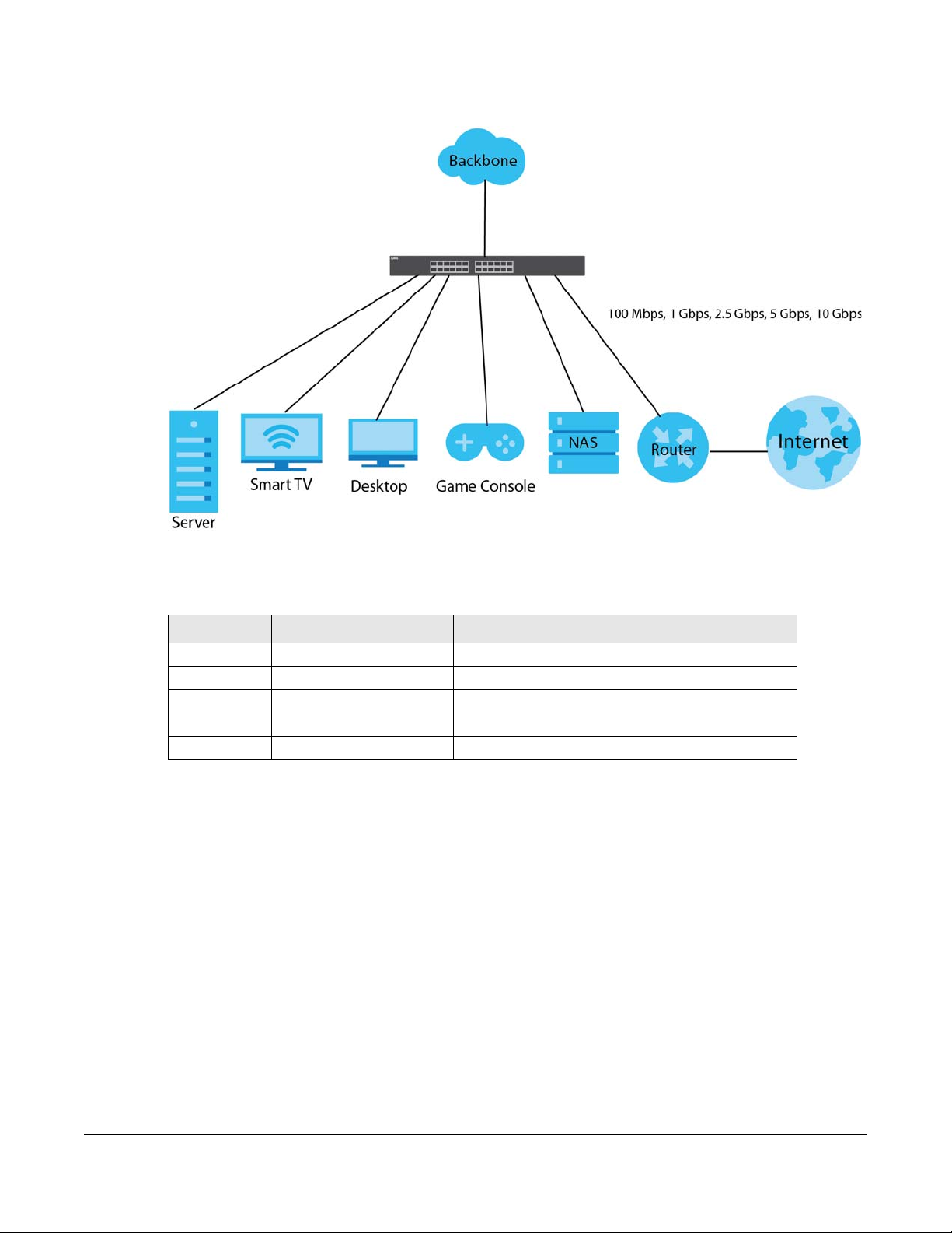
Chapter 1 Getting to Know Your Switch
Figure 1 Multi-Gigabit Application
See the following table for the cables required and distance limitation to attain the corresponding
speed.
Table 2 Cable Types
CABLE TRANSMISSION SPEED MAXIMUM DISTANCE BANDWIDTH CAPACITY
Category 5 100M 100 m 100 MHz
Category 5e 1G / 2.5G / 5G 100 m 100 MHz
Category 6 5G / 10G 50 m 250 MHz
Category 6a 10G 100 m 500 MHz
Category 7 10G 100 m 650 MHz
Note: Make sure to select the correct speed for the port in PORT > Port Setup.
1.1.2 Management Modes
NebulaFlex means you can set the Switch to operate in either standalone or cloud mode (but not both
at the same time).
Use the DHCP-assigned IP address to access the Web Configurator. To know the IP address, use the
NCC, the ZON utility, or the console port if available. You can also use the domain name “setup.zyxel” to
access the Web Configurator when you are directly connected to the Switch.
Note: Make sure your computer can connect to a DNS server through the Switch.
Use the Web Configurator to configure and manage the Switch directly in standalone mode or use
Nebula Control Center (NCC) to configure and manage the Switch in cloud mode. The Nebula Control
Center (NCC) is an alternative cloud-based network management system that allows you to remotely
XGS2220 Series User’s Guide
30

Chapter 1 Getting to Know Your Switch
manage and monitor the Switch. You may also access a minimized version of the Web Configurator in
cloud mode.
Nebula Cloud Management
To have Nebula manage the Switch, you must first register it at the Nebula web portal at https://
nebula.zyxel.com, and ensure that Nebula Control Center (NCC) Discovery is enabled in SYSTEM >
Cloud Management in the Switch Web Configurator.
Note: See the Switch’s datasheet for the feature differences between standalone and
Nebula cloud management modes. You can find the Switch’s datasheet at the Zyxel
website.
See the NCC (Nebula Control Center) User’s Guide for how to configure the Switch using Nebula.
Figure 2 NCC Example Network Topology
1.1.3 Mode Changing
This section describes how to change the Switch’s management mode. Refer to the Switch’s
standalone mode User’s Guide for LED descriptions, including CLOUD LED behavior.
From Standalone to Nebula Cloud Management
To manage your Switch through Nebula, connect the Switch to the Internet, and register it to a site and
organization at the Nebula web portal (https://nebula.zyxel.com).
See the following steps or the Switch Quick Start Guide for registering the Switch.
XGS2220 Series User’s Guide
31

Chapter 1 Getting to Know Your Switch
Go to the NCC to Register the Switch
1 Go to the Nebula web portal in one of three ways.
• Enter https://nebula.zyxel.com in a supported web browser. See the Nebula User’s Guide for more
information about supported browsers.
• Click Visit Nebula in the Switch’s login page.
• Click the Nebula Control Center icon in the upper right of the Switch’s Web Configurator.
2 Click Get Started in the Nebula web portal. Enter your myZyxel account information. You will be
redirected to another screen where you can sign up for a myZyxel account if you do not have one.
3 Create an organization and a site (using the Nebula setup wizard) or select an existing site.
4 Register the Switch by entering its Registration MAC address and serial number and assign it to the site.
The serial number and Registration MAC address can be found in the DASHBOARD screen or the device
back label on the Switch.
Use the Zyxel Nebula Mobile App to Register the Switch
1 Download and open the Zyxel Nebula Mobile app in your mobile device (see Section on page 155 to
download the app). Click Start on the first page. Click Create account to create a myZyxel account or
enter your existing account information to log in.
2 Create an organization and site, or select an existing site using the Zyxel Nebula Mobile app.
3 Select a site and scan the Switch's QR code or manually enter the information to add it to the site. You
can find the QR code:
• On a label on the Switch or
• On its box or
• In the Web Configurator at SYSTEM > Cloud Management.
See Section 3.3 on page 53 for more information about the CLOUD LED or Section Table 33 on page 118
for more information about the Cloud Control Status field in the DASHBOARD screen to see if the Switch
goes into Nebula cloud management mode successfully.
The Switch goes into Nebula-managed mode automatically after it can
access the Nebula web portal and is successfully registered there. Its
login password and settings are then overwritten with what you have
configured in the Nebula web portal. To access the Web Configurator
when the Switch is in Cloud mode, use the Local credentials password
to login.
Note: The Local credentials: Password can be found in Site-wide > Configure > General
settings > Device configuration in the NCC portal. See the NCC User’s Guide for more
information.
XGS2220 Series User’s Guide
32

Chapter 1 Getting to Know Your Switch
Table 3 Management Method Comparison
MODE ACCESS LOGIN USER NAME LOGIN PASSWORD
Cloud mode NCC (Nebula
Control Center)
portal
Web
Configurator
(Local GUI)
myZyxel account
name
admin Local credentials
myZyxel account
password
password
LOGIN IP ADDRESS/URL/
DOMAIN NAME
https://nebula.zyxel.com
http://setup.zyxel
OR
http://DHCP-assigned IP
OR
a configured static IP address
Note: The Web Configurator (Local GUI) of Cloud mode supports limited features for troubleshooting
use only.
Standalone
mode
Web
Configurator
admin 1234 http://setup.zyxel
OR
http://DHCP-assigned IP
OR
http://192.168.1.1
From Nebula-managed to Standalone
To return to direct management standalone mode, remove (unregister) the Switch from the inventory in
the Nebula web portal.
Note: When you change the Switch’s management mode from Nebula-manged mode to
standalone mode, the Switch will reboot and restore its factory-default settings.
To unregister the Switch:
1 Go to the Nebula Control Center (https://nebula.zyxel.com).
2 Go to the Organization-wide > License & inventory > Devices screen.
3 Select the Switch you want to remove (unregister) from the organization.
4 Click Actions, then click Remove from organization.
It will take a while for the Switch to reboot and reset to factory default.
1.1.4 ZON Utility
With its built-in Web Configurator, including the Neighbor Management feature (Section 13.1 on page
132), viewing, managing and configuring the Switch and its neighboring devices is simplified.
In addition, Zyxel offers a proprietary software program called Zyxel One Network (ZON) Utility, it is a
utility tool that assists you to set up and maintain network devices in a more simple and efficient way.
You can download the ZON Utility at www.zyxel.com and install it on a PC (Windows operation system).
For more information on ZON Utility see Section 4.3 on page 62.
XGS2220 Series User’s Guide
33

Chapter 1 Getting to Know Your Switch
1.1.5 Web Configurator Networked AV Mode
Aside from the Web Configurator in Standard mode, you can switch to Networked AV mode that is
specifically designed to simplify configuration and management of the Switch for AVoIP (Audio-Video
over Internet Protocol) application. In AV over IP, the AV transmitter is the transmitter, the AV receiver is
the receiver, and the matrix switch is a standard IP Switch. See Section 4.4 on page 66 for details on
using the Setup Wizard screen for configuring the Switch’s Networked AV mode’s basic and advanced
settings.
Figure 3 Comparison Between Traditional AV and AVoIP Setups
1.1.6 PoE
The Switch is a Power Sourcing Equipment (PSE) because it provides a source of power through its
Ethernet ports. Each device that receives power through an Ethernet port is a Powered Device (PD).
The Switch can adjust the power supplied to each PD according to the PoE standard the PD supports.
PoE standards are:
• IEEE 802.3af Power over Ethernet (PoE)
• IEEE 802.3at Power over Ethernet (PoE) +
• IEEE 802.3bt Power over Ethernet (PoE) ++
The following table describes the PoE features of the Switch by model.
Table 4 XGS2220 Series Models and PoE Features
POE FEATURES XGS2220-30HP XGS2220-54HP XGS2220-54FP
IEEE 802.3at PoE+ Ports 1 – 16 Ports 1 – 40 Ports 1 – 40
IEEE 802.3bt PoE++ Ports 17 – 26 Ports 41 – 50 Ports 41 – 50
Power Management Mode Consumption
Classification (default)
PoE Power Budget 400 W 600 W 960 W
Consumption
Classification (default)
Consumption
Classification (default)
XGS2220 Series User’s Guide
34

Chapter 1 Getting to Know Your Switch
Table 5 PoE Standards
PoE FEATURES PoE PoE+ PoE++
IEEE Standard IEEE 802.3af IEEE 802.3at IEEE 802.3bt
PoE Type Type 1 Type 2 Type 3
Switch Port Power
Maximum Power Per Port 15.4 W 30 W 60 W
Port Voltage Range 44 – 57 V 50 – 57 V 50 – 57 V
Cables
Twisted Pairs Used 2-pair 2-pair 4-pair
Supported Cables Cat3 or better Cat5 or better Cat5 or better
1.2 Example Applications
This section shows a few examples of using the Switch in various network environments. Note that the
Switch in the figure is just an example Switch and not your actual Switch.
1.2.1 PoE Example Application
The following example figure shows a Switch supplying PoE (Power over Ethernet) to Powered Devices
(PDs) such as an IP camera, a wireless router, an IP telephone and a general outdoor router that are not
within reach of a power outlet.
Figure 4 PoE Example Application
XGS2220 Series User’s Guide
35

Chapter 1 Getting to Know Your Switch
1.2.2 Backbone Example Application
The Switch is an ideal solution for small networks where rapid growth can be expected in the near future.
The Switch can be used standalone for a group of heavy traffic users. You can connect computers and
servers directly to the Switch’s port or connect other switches to the Switch.
In this example, all computers can share high-speed applications on the server. To expand the network,
simply add more networking devices such as switches, routers, computers, print servers, and so on.
Figure 5 Backbone Application
1.2.3 Bridging Example Application
In this example, the Switch connects different company departments (RD and Sales) to the corporate
backbone. It can alleviate bandwidth contention and eliminate server and network bottlenecks. All
users that need high bandwidth can connect to high-speed department servers through the Switch.
You can provide a super-fast uplink connection by using a Gigabit Ethernet or SFP port on the Switch.
Moreover, the Switch eases supervision and maintenance by allowing network managers to centralize
multiple servers at a single location.
XGS2220 Series User’s Guide
36

Chapter 1 Getting to Know Your Switch
Figure 6 Bridging Application
1.2.4 High Performance Switching Example
The Switch is ideal for connecting two geographically dispersed networks that need high bandwidth. In
the following example, a company uses the 10 Gigabit uplink ports to connect the headquarters to a
branch office network. Within the headquarters network, a company can use trunking to group several
physical ports into one logical higher-capacity link. Trunking can be used if for example, it is cheaper to
use multiple lower-speed links than to under-utilize a high-speed, but more costly, single-port link.
Figure 7 High Performance Switching
1.2.5 IEEE 802.1Q VLAN Application Examples
A VLAN (Virtual Local Area Network) allows a physical network to be partitioned into multiple logical
networks. Stations on a logical network belong to one or more groups. With VLAN, a station cannot
directly talk to or hear from stations that are not in the same groups unless such traffic first goes through
a router.
XGS2220 Series User’s Guide
37

Chapter 1 Getting to Know Your Switch
1.2.5.1 Tag-based VLAN Example
Ports in the same VLAN group share the same frame broadcast domain thereby increase network
performance through reduced broadcast traffic. VLAN groups can be modified at any time by adding,
moving or changing ports without any re-cabling.
Shared resources such as a server can be used by all ports in the same VLAN as the server. In the
following figure only ports that need access to the server need to be part of VLAN 1. Ports can belong to
other VLAN groups too.
Figure 8 Shared Server Using VLAN Example
1.2.6 IPv6 Support
IPv6 (Internet Protocol version 6), is designed to enhance IP address size and features. The increase in
IPv6 address size to 128 bits (from the 32-bit IPv4 address) allows up to 3.4 x 10
of writing, the Switch supports the following features.
• Static address assignment and stateless auto-configuration
• Neighbor Discovery Protocol (a protocol used to discover other IPv6 devices in a network)
• Remote Management using ping, SNMP, SSH, telnet, HTTP and FTP services
• ICMPv6 to report errors encountered in packet processing and perform diagnostic functions, such as
"ping”
• IPv4/IPv6 dual stack; the Switch can run IPv4 and IPv6 at the same time
• DHCPv6 client and relay
• Multicast Listener Discovery (MLD) snooping and proxy
For more information on IPv6, refer to Appendix C on page 629 and the CLI Reference Guide.
1.3 Ways to Manage the Switch
Use any of the following methods to manage the Switch.
38
IP addresses. At the time
• NCC (Zyxel Nebula Control Center). With the NCC, you can remotely manage and monitor the
Switch through a cloud-based network management system. See the NCC User’s Guide for detailed
information about how to access the NCC and manage your Switch through the NCC. See the NCC
User’s Guide for how to configure Nebula managed devices.
XGS2220 Series User’s Guide
38

Chapter 1 Getting to Know Your Switch
• Web Configurator. This is recommended for everyday management of the Switch using a (supported)
web browser. See Chapter 4 on page 57.
• Command Line Interface. Line commands offer an alternative to the Web Configurator and in some
cases are necessary to configure advanced features. See the CLI Reference Guide.
• FTP. Use File Transfer Protocol for firmware upgrades and configuration backup or restore. See Section
78.3.1 on page 535.
• SNMP. The Switch can be monitored and/or managed by an SNMP manager. See Section 26.6.1 on
page 195.
• Cluster Management. Cluster Management allows you to manage multiple switches through one
switch, called the cluster manager. See Chapter 78 on page 537.
• ZON Utility. ZON Utility is a program designed to help you deploy and perform initial setup on a
network more efficiently. See Section 4.3 on page 62.
1.4 Good Habits for Managing the Switch
Do the following regularly to make the Switch more secure and to manage the Switch more effectively.
• Change the password. Use a password that is not easy to guess and that consists of different types of
characters, such as numbers and letters.
• Write down the password and put it in a safe place.
• Back up the configuration (and make sure you know how to restore it). Restoring an earlier working
configuration may be useful if the device becomes unstable or even crashes. If you forget your
password, you will have to reset the Switch to its factory default settings. If you backed up an earlier
configuration file, you would not have to totally re-configure the Switch. You could simply restore your
last configuration.
XGS2220 Series User’s Guide
39

Hardware Installation and
2.1 Installation Scenarios
This chapter shows you how to install and connect the Switch.
The Switch can be:
• Placed on a desktop.
• Rack-mounted on a standard EIA rack.
CHAPTER 2
Connection
2.2 Safety Precautions
Please observe the following before using the Switch:
• It is recommended to ask an authorized technician to attach the Switch on a desk or to the rack or
wall. Use the proper screws to prevent damage to the Switch. See the Installation Requirements
sections in this chapter to know the types of screws and screwdrivers for each mounting method.
• Make sure there is at least 2 cm of clearance on the top and bottom of the Switch, and at least 5 cm
of clearance on all four sides of the Switch. This allows air circulation for cooling.
• Do NOT block the ventilation holes nor store cables or power cords on the Switch. Allow clearance for
the ventilation holes to prevent your Switch from overheating. This is especially crucial when your
Switch does not have fans. Overheating could affect the performance of your Switch, or even
damage it.
• The surface of the Switch could be hot when it is functioning. Do NOT put your hands on it. You may
get burned. This could happen especially when you are using a fanless Switch.
• The Switches with fans are not suitable for use in locations where children are likely to be present.
To start using the Switch, simply connect the power cables to turn it on.
2.3 Freestanding Installation Procedure
1 Make sure the Switch is clean and dry.
2 Remove the adhesive backing from the rubber feet.
XGS2220 Series User’s Guide
40

Chapter 2 Hardware Installation and Connection
3 Attach the rubber feet to each corner on the bottom of the Switch. These rubber feet help protect the
Switch from shock or vibration and ensure space between devices when stacking.
Figure 9 Attaching Rubber Feet
4 Set the Switch on a smooth, level surface strong enough to support the weight of the Switch and the
connected cables. Make sure there is a power outlet nearby.
Cautions:
• Avoid stacking fanless Switches to prevent overheating.
• Ensure enough clearance around the Switch to allow air circulation for cooling.
• Do NOT remove the rubber feet as it provides space for air circulation.
2.4 Mounting the Switch on a Rack
The Switch can be mounted on an EIA standard size, 19-inch rack or in a wiring closet with other
equipment. Follow the steps below to mount your Switch on a standard EIA rack using a rack-mounting
kit.
Note: Make sure there is enough clearance between each equipment on the rack for air
circulation.
2.4.1 Installation Requirements
• Two mounting brackets.
• Eight M3 flat head screws and a #2 Philips screwdriver.
• Four M5 flat head screws and a #2 Philips screwdriver.
2.4.2 Precautions
• Make sure the rack will safely support the combined weight of all the equipment it contains. The
maximum weight a bracket can hold is 21.5 kg.
• Make sure the position of the Switch does not make the rack unstable or top-heavy. Take all
necessary precautions to anchor the rack securely before installing the unit.
XGS2220 Series User’s Guide
41

Chapter 2 Hardware Installation and Connection
2.4.3 Attaching the Mounting Brackets to the Switch
1 Position a mounting bracket on one side of the Switch, lining up the four screw holes on the bracket with
the screw holes on the side of the Switch.
Figure 10 Attaching the Mounting Brackets
2 Using a #2 Philips screwdriver, install the M3 flat head screws through the mounting bracket holes into
the Switch.
3 Repeat steps 1 and 2 to install the second mounting bracket on the other side of the Switch.
4 You may now mount the Switch on a rack. Proceed to the next section.
2.4.4 Mounting the Switch on a Rack
1 Position a mounting bracket (that is already attached to the Switch) on one side of the rack, lining up
the two screw holes on the bracket with the screw holes on the side of the rack.
Figure 11 Mounting the Switch on a Rack
2 Using a #2 Philips screwdriver, install the M5 flat head screws through the mounting bracket holes into
XGS2220 Series User’s Guide
42

Chapter 2 Hardware Installation and Connection
the rack.
Note: Make sure you tighten all the four screws to prevent the Switch from getting slanted.
3 Repeat steps 1 and 2 to attach the second mounting bracket on the other side of the rack.
XGS2220 Series User’s Guide
43

Chapter 3 Hardware Panels
Hardware Panels
This chapter describes the front panel and rear panel of the Switch and shows you how to make the
hardware connections.
3.1 Front Panel Connections
The following figures show the front panels of the Switch.
Figure 12 Front Panel: XGS2220-30
CHAPTER 3
Figure 13 Front Panel: XGS2220-30HP
Figure 14 Front Panel: XGS2220-30F
Figure 15 Front Panel: XGS2220-54
Figure 16 Front Panel: XGS2220-54HP
Figure 17 Front Panel: XGS2220-54FP
XGS2220 Series User’s Guide
44

Chapter 3 Hardware Panels
The following table describes the ports.
Table 6 Front Panel Connections
CONNECTOR DESCRIPTION
24/48 1000Base-T
RJ-45 Ethernet Ports
2 10GBase-T RJ-45
Ethernet Ports
16/40 1000Base-T
RJ-45 PoE Ports
8 1000Base-T RJ-45
PoE Ports
2 10GBase-T RJ-45
PoE Ports
4 1/10G SFP+ Slots Use SFP+ transceivers in these ports for high-bandwidth backbone connections. You can
Reset Press the RESET button to reboot the Switch without turning the power off. See Section 3.3 on
Restore
These are 10/100/1000Base-T auto-negotiating and auto-crossover Ethernet ports.
Connect these ports to a computer, a hub, a router, or an Ethernet switch.
These are 1/2.5/5/10G auto-negotiating and auto-crossover Ethernet ports.
Connect these ports to a gaming computer, a NAS (network-attached storage), or a server.
These are 10/100/1000Base-T auto-negotiating and auto-crossover IEEE802.3at PoE+ 30 W
ports.
Connect these ports to a PTZ (pan, tilt and zoom) camera, a WiFi 6 (802.11ax) router, a WiFi 6
(802.11ax) AP, or an Ethernet switch.
These are 10/100/1000Base-T auto-negotiating and auto-crossover IEEE802.3bt PoE++ 60 W
ports.
Connect these ports to a PTZ (pan, tilt and zoom) camera, a WiFi 6 (802.11ax) router, a WiFi 6
(802.11ax) AP, or an Ethernet switch.
These are 1G, 2.5G, 5G, and 10G auto-negotiating and auto-crossover IEEE802.3bt PoE++ 60
W ports.
Connect these ports to a PTZ (pan, tilt and zoom) camera, a WiFi 6 (802.11ax) router, a WiFi 6
(802.11ax) AP, or an Ethernet switch.
also insert an SFP+ Direct Attach Copper (DAC) in the SFP+ slot.
page 53 for more information about the LED behavior.
IN STANDALONE MODE
Press the RESTORE button for 3 to 7 seconds to have the Switch automatically reboot and
restore the last-saved custom default file. See Section 3.3 on page 53 for more information
about the LED behavior.
Press the RESTORE button for more than 7 seconds to have the Switch automatically reboot
and restore the factory default file. See Section 3.3 on page 53 for more information about
the LED behavior.
IN NEBULA CLOUD MODE
Press the RESTORE button for more than 7 seconds to have the Switch automatically reboot
and restore the factory default file.
3.1.1 Gigabit Ethernet Ports
The Switch has 1000Base-T auto-negotiating, auto-crossover Ethernet ports. In 10/100/1000 Mbps Gigabit
Ethernet, the speed can be 10 Mbps, 100 Mbps or 1000 Mbps. The duplex mode can be half duplex or
full duplex.
An auto-negotiating port can detect and adjust to the optimum Ethernet speed (10/100/1000 Mbps)
and duplex mode (full duplex or half duplex) of the connected device.
An auto-crossover (auto-MDI/MDI-X) port automatically works with a straight-through or crossover
Ethernet cable.
When auto-negotiation is turned on, an Ethernet port negotiates with the peer automatically to
determine the connection speed and duplex mode. If the peer Ethernet port does not support auto-
XGS2220 Series User’s Guide
45

negotiation or turns off this feature, the Switch determines the connection speed by detecting the signal
on the cable and using half duplex mode. When the Switch’s auto-negotiation is turned off, an Ethernet
port uses the pre-configured speed and duplex mode when making a connection, thereby requiring
you to make sure that the settings of the peer Ethernet port are the same in order to connect.
3.1.1.1 Default Ethernet Negotiation Settings
The factory default negotiation settings for the Gigabit ports on the Switch are:
• Speed: Auto
•Duplex: Auto
• Flow control: Off
• Link Aggregation: Disabled
3.1.1.2 Auto-crossover
All ports support auto-crossover, that is auto-MDIX ports (Media Dependent Interface Crossover), so you
may use either a straight-through Ethernet cable or crossover Ethernet cable for all Gigabit port
connections. Auto-crossover ports automatically sense whether they need to function as crossover or
straight ports, so crossover cables can connect both computers and switches or hubs.
3.1.2 SFP/SFP+ Slots
These are four slots for Small Form-Factor Pluggable (SFP) or SFP+ modules, such as an SFP or SFP+
transceiver. The SFP+ (SFP Plus) is an enhanced version of the SFP and supports data rates of 10 Gbps. A
transceiver is a single unit that houses a transmitter and a receiver. Use a transceiver to connect a fiber
optic cable to the Switch. The Switch does not come with transceivers. You must use transceivers that
comply with the Small Form-Factor Pluggable (SFP) Transceiver MultiSource Agreement (MSA). See the
SFF committee’s INF-8074i specification Rev 1.0 for details.
You can change transceivers while the Switch is operating. You can use different transceivers to
connect to Ethernet switches with different types of fiber optic connectors.
• Type: SFP or SFP+ connection interface
• Connection speed: 1 or 10 Gigabit per second (Gbps)
WARNING! To avoid possible eye injury, do not look into an operating
fiber optic module’s connectors.
HANDLING! All transceivers are static sensitive. To prevent damage from
electrostatic discharge (ESD), it is recommended you attach an ESD
preventive wrist strap to your wrist and to a bare metal surface when
you install or remove a transceiver.
STORAGE! All modules are dust sensitive. When not in use, always keep
the dust plug on. Avoid getting dust and other contaminant into the
optical bores, as the optics do not work correctly when obstructed with
dust.
3.1.2.1 Transceiver Installation
Use the following steps to install a transceiver.
1 Attach an ESD preventive wrist strap to your wrist and to a bare metal surface.
XGS2220 Series User’s Guide
46

Chapter 3 Hardware Panels
2 Align the transceiver in front of the slot opening.
3 Make sure the latch is in the lock position (latch styles vary), then insert the transceiver into the slot with
the exposed section of PCB board facing down.
4 Press the transceiver firmly until it clicks into place.
5 The Switch automatically detects the installed transceiver. Check the LEDs to verify that it is functioning
properly.
6 Remove the dust plugs from the transceiver and cables (dust plug styles vary).
7 Identify the signal transmission direction of the fiber optic cables and the transceiver. Insert the fiber
optic cable into the transceiver.
Figure 18 Latch in the Lock Position
Figure 19 Transceiver Installation Example
Figure 20 Connecting the Fiber Optic Cables
3.1.2.2 Transceiver Removal
Use the following steps to remove an SFP transceiver.
1 Attach an ESD preventive wrist strap to your wrist and to a bare metal surface on the chassis.
2 Remove the fiber optic cables from the transceiver.
3 Pull out the latch and down to unlock the transceiver (latch styles vary).
Note: Make sure the transceiver’s latch is pushed all the way down, so the transceiver can be
pulled out successfully.
4 Pull the latch, or use your thumb and index finger to grasp the tabs on both sides of the transceiver, and
carefully slide it out of the slot.
XGS2220 Series User’s Guide
47

Chapter 3 Hardware Panels
Note: Do NOT pull the transceiver out by force. You could damage it. If the transceiver will not
slide out, grasp the tabs on both sides of the transceiver with a slight up or down motion
and carefully slide it out of the slot. If unsuccessful, contact Zyxel Support to prevent
damage to your Switch and transceiver.
5 Insert the dust plug into the ports on the transceiver and the cables.
Figure 21 Removing the Fiber Optic Cables
Figure 22 Opening the Transceiver’s Latch Example
Figure 23 Transceiver Removal Example
3.1.3 Console Port
This USB Type C connector is for troubleshooting only.
3.2 Rear Panel
The following figures show the rear panels of the Switch. The rear panels contain:
Figure 24 Rear Panel: XGS2220-30
Figure 25 Rear Panel: XGS2220-30HP
XGS2220 Series User’s Guide
48

Chapter 3 Hardware Panels
Figure 26 Rear Panel: XGS2220-30F
Figure 27 Rear Panel: XGS2220-54
Figure 28 Rear Panel: XGS2220-54HP
Figure 29 Rear Panel: XGS2220-54FP
3.2.1 Grounding
Grounding is a safety measure to direct excess electric charge to the ground. It prevents damage to
the Switch, and protects you from electrocution. Use the grounding screw on the rear panel and the
ground wire of the AC power supply to ground the Switch.
The grounding terminal and AC power ground where you install the Switch must follow your country’s
regulations. Qualified service personnel must ensure the building’s protective earthing terminals are
valid terminals.
Installation of Ethernet cables must be separate from AC power lines. To avoid electric surge and
electromagnetic interference, use a different electrical conduit or raceway (tube/trough or enclosed
conduit for protecting electric wiring) that is 15 cm apart, or as specified by your country’s electrical
regulations.
Any device that is located outdoors and connected to this product must be properly grounded and
surge protected. To the extent permissible by your country’s applicable law, failure to follow these
guidelines could result in damage to your Switch which may not be covered by its warranty.
Note: The specification for surge or ESD protection assumes that the Switch is properly
grounded.
1 Remove the M4 ground screw from the Switch’s rear panel.
2 Secure a green or yellow ground cable (16 AWG or smaller) to the Switch's rear panel using the M4
ground screw.
XGS2220 Series User’s Guide
49

Chapter 3 Hardware Panels
Figure 30 Grounding
3 Attach the other end of the ground cable to a grounding bar located on the rack where you install the
Switch or to an on-site grounding terminal.
Figure 31 Attach Ground Cable to Grounding Bar or On-site Grounding Terminal
4 The grounding terminal of the server rack or on-site grounding terminal must also be grounded and
connected to the building’s main grounding electrode. Make sure the grounding terminal is connected
to the buildings grounding electrode and has an earth resistance of less than 10 ohms, or according to
your country’s electrical regulations.
Figure 32 Connecting to the Building’s Main Grounding Electrode
If you are uncertain that suitable grounding is available, contact the appropriate electrical inspection
XGS2220 Series User’s Guide
50

authority or an electrician.
This device must be grounded. Do this before you make other
connections.
3.2.2 AC Power Connection
Note: Make sure you are using the correct power source as shown on the panel and that no
objects obstruct the airflow of the fans (located on the side of the unit).
To connect power to the Switch, insert the female end of the power cord to the AC power receptacle
on the rear panel. Connect the other end of the supplied power cord to a power outlet.
Power Cord Requirement (XGS2220-54HP / XGS2220-54FP)
Make sure to use the provided or designated power cord for your
Switch.
The following table describes the power cord requirements for XGS2220-54HP / XGS2220-54FP.
Chapter 3 Hardware Panels
Table 7 XGS2220-54HP / XGS2220-54FP Power Cord Specifications
COUNTRIES SPECIFICATION SUPPLY VOLTAGE
Europe and United Kingdom 18 AWG 230 V
North America 14 AWG 110 V
Note: If you need to replace the power cord, contact your local vendor.
Installing the Retainer Clip
Install the retainer clip to prevent accidental removal of the power cord.
1 Loosely wrap the clip on the retainer to the power cord.
2 Push the pronged-end of the retainer clip into the Retainer Holder hole until it locks into place.
XGS2220 Series User’s Guide
51

Chapter 3 Hardware Panels
3 Slide the clip up to the end of the power cord.
4 Close the clip tightly around the power cord until secure.
XGS2220 Series User’s Guide
52

3.3 LEDs
After you connect the power to the Switch, view the LEDs to ensure proper functioning of the Switch
and as an aid in troubleshooting.
Table 8 LED Descriptions
LED COLOR STATUS DESCRIPTION
PWR/SYS Green On The Switch is on and functioning properly.
CLOUD Green On The Switch has successfully connected to the NCC (Nebula
LOCATOR Blue On The Switch is uploading firmware. While the Switch is doing this,
PoE MAX
(XGS2220-30HP /
XGS2220-54HP /
XGS2220-54FP)
STACK ID The LED is showing the Stack ID number of the Switch.
PRIMARY Green On The Switch is acting as a standalone switch or the master in
Chapter 3 Hardware Panels
Blinking The Switch is rebooting and performing self-diagnostic tests.
Yellow On The Switch is functioning abnormally, FAN status alert/error, or
the system power detected is under 10.8 V.
Blinking The Switch is returning to its factory default configuration
settings.
Off The Switch is not receiving power from the power source.
Control Center).
Blinking The Switch cannot connect to the NCC because it is not
registered. Please register the Switch with NCC.
Yellow On The Switch is registered with NCC but cannot connect to the
NCC. Please check the Internet connection of the Switch.
Blinking The Switch is not registered with NCC and cannot connect to
the NCC. Please check the Internet connection of the Switch
and register the Switch with NCC.
Off The Switch is operating in standalone mode. Nebula Control
Center (NCC) Discovery is disabled in SYSTEM > Cloud
Management in the Switch Web Configurator.
do not turn off the power.
Blinking Shows the actual location of the Switch between several
devices in a rack. The default timer is 30 minutes when you are
configuring the Switch.
Off The locator is not functioning or malfunctioning.
Red On PoE power usage is more than 95 percent of the power
supplied budget.
Yellow On PoE power usage is below 95 percent of the power supplied
budget, but over 80 percent of the power supplied budget.
Off PoE power usage is below 80 percent of the power supplied
budget.
ID 0 means it is a standalone Switch.
stacking.
Yellow On An error occurred when the Switch is selected as the master
member in a stack.
Off The Switch is acting as a non-master member in a stack.
XGS2220 Series User’s Guide
53

Chapter 3 Hardware Panels
LED COLOR STATUS DESCRIPTION
10M/100M/1000M Base-T Ports
Link / ACT
1 – 24
(XGS2220-30 /
XGS2220-30HP)
1 – 48
(XGS2220-54 /
XGS2220-54HP /
XGS2220-54FP)
1G/2.5G/5G/10G Base-T Ports
Link / ACT
25 – 26
(XGS2220-30 /
XGS2220-30HP /
XGS2220-30F)
49 – 50
(XGS2220-54 /
XGS2220-54HP /
XGS2220-54FP)
Green On The link to a 1000M Ethernet network is up.
Blinking The Switch is transmitting/receiving to/from a 1000M Ethernet
network.
Yellow On The link to a 10M/100M Ethernet network is up.
Blinking The Switch is transmitting/receiving to/from a 10M/100M
Ethernet network.
Off The link to an Ethernet network is down.
Blue On The link to a 10G Ethernet network is up.
Blinking The Switch is transmitting/receiving to/from a 10G Ethernet
network.
Green On The link to a 1G/2.5G/5G Ethernet network is up.
Blinking The Switch is transmitting/receiving to/from a 1G/2.5G/5G
Ethernet network.
Off The link to an Ethernet network is down.
PoE Mode
1 – 16
(XGS2220-30HP)
1 – 40
(XGS2220-54HP /
XGS2220-54FP)
17 – 26
(XGS2220-30HP)
41 – 50
(XGS2220-54HP /
XGS2220-54FP)
Green On Power supplied to all PoE Ethernet ports meets the IEEE 802.3at
or IEEE 802.3af standard.
Off There is no power supplied.
Yellow On Power supplied to all PoE Ethernet ports meets the IEEE 802.3bt
standard.
Green On Power supplied to all PoE Ethernet ports meets the IEEE 802.3at
/ IEEE 802.3af standards.
Off There is no power supplied.
XGS2220 Series User’s Guide
54

Chapter 3 Hardware Panels
LED COLOR STATUS DESCRIPTION
1G SFP Slots
Link / ACT
1 – 24
(XGS2220-30F)
Green On The port has a successful 1000M connection.
Blinking The port is transmitting or receiving data at 1000M.
Yellow On The port has a successful 100M connection.
Blinking The port is transmitting or receiving data at 100M.
Off This link is disconnected.
LED COLOR STATUS DESCRIPTION
1G/10G SFP+ Slots
Link / ACT
27 – 30
(XGS2220-30 /
XGS2220-30HP /
XGS2220-30F)
51 – 54
(XGS2220-54 /
XGS2220-54HP /
XGS2220-54FP)
Blue On The port has a successful 10G connection.
Blinking The port is transmitting or receiving data at 10G.
Green On The port has a successful 1000M connection.
Blinking The port is transmitting or receiving data at 1000M.
Off This link is disconnected.
XGS2220 Series User’s Guide
55

PART II
Technical Reference
56

4.1 Overview
This section introduces the configuration and functions of the Web Configurator.
The Web Configurator is an HTML-based management interface that allows easy system setup and
management through Internet browser. Use a browser that supports HTML5, such as Microsoft Edge,
Mozilla Firefox, or Google Chrome. The recommended minimum screen resolution is 1024 by 768 pixels.
In order to use the Web Configurator you need to allow:
• Web browser pop-up windows on your computer.
• JavaScript (enabled by default).
• Java permissions (enabled by default).
CHAPTER 4
Web Configurator
4.2 System Login
1 Start your web browser.
2 The Switch is a DHCP client by default. Type “http://DHCP-assigned IP” in the Location or Address field.
Press [ENTER].
Note: You can always use the domain name “setup.zyxel” to access the Web Configurator
whether the Switch is using a DHCP-assigned IP or static IP address. This requires your
computer to be directly connected to the Switch. Make sure your computer can
connect to a DNS server through the Switch.
If the Switch is not connected to a DHCP server, enter “http://” and the static IP address of the Switch
(for example, the default management IP address is 192.168.1.1 through an in-band port) in the Location
or Address field. Press [ENTER]. Your computer must be in the same subnet in order to access this website
address.
Also, you can use the ZON Utility to check your Switch’s IP address. See Section 4.3 on page 62 for more
information on the ZON utility.
3 The Login screen appears.
XGS2220 Series User’s Guide
57

Chapter 4 Web Configurator
Figure 33 Web Configurator: Login
4 Click the Visit Nebul a button if you want to open the Zyxel Nebula Control Center (NCC) login page in a
new tab or window. The NCC is a cloud-based network management system that allows you to
remotely manage and monitor the Switch. See Section 1.1.3 on page 31 for information on changing
your Switch to Nebula Cloud management.
Figure 34 Visit Nebula
5 Click Login to log into the Web Configurator to manage the Switch directly. The default user name is
admin and associated default password is 1234.
6 The Select Mode screen appears.
XGS2220 Series User’s Guide
58

Chapter 4 Web Configurator
Figure 35 Select Mode
7 Select the Web Configurator in Standard Mode that has a complete set of configuration for network
installation. Or select the Web Configurator in Networked AV Mode that has a set of menus specifically
designed to simplify configuration and management of the Switch for AVoIP (Audio-Video over Internet
Protocol) application.
8 If you select Standard Mode, go directly to step 10.
9 The Setup Wizard screen will appear after selecting the Networked AV Mode. You can use the Setup
Wizard screen to configure the Switch’s Networked AV mode’s basic or advanced settings (see Section
4.4 on page 66 for details).
• Use the Basic Settings to configure networked AV operation on management VLAN. Such as the
Switches’ IP address, DNS server, system password, SNMP community, accept or skip the default
Networked AV mode settings, and view a summary of the basic settings.
• Use the Advanced Settings for networks that wants to separate networked AV VLAN from
management VLAN, specify which ports connect to AVoIP application, and for setting link
aggregation across switches.
Once you click the Finish button, the settings configured in the Setup Wizard screen will overwrite the
existing settings.
Otherwise, click the Exit button. If you want to open the Setup Wizard screen later, click the Wizard icon
in the upper right hand corner of the Web Configurator in Networked AV mode.
XGS2220 Series User’s Guide
59

Chapter 4 Web Configurator
Figure 36 Web Configurator: Wizard
10 If you did not change the default administrator password and/or SNMP community values, a warning
screen displays each time you log into the Web Configurator and select Standard Mode. Click Password
/ SNMP to open a screen where you can change the administrator password and SNMP community
string simultaneously. Otherwise, click Ignore to close it.
If you log into the Web Configurator and select Networked AV Mode, open the screen in the Wizard >
Step 2 Password to change the administrator password and SNMP community string. Click Finish on the
last step of the Wizard to save your settings.
Password/SNMP Setting
Figure 37 Web Configurator: Warning
XGS2220 Series User’s Guide
60

Chapter 4 Web Configurator
Figure 38 Web Configurator: Password/SNMP
Note: The input string of any field in this screen should not contain [ ? ], [ | ], [ ' ], [ " ], or [ , ].
In the Password fields, [ space ] is also not allowed.
Change the default administrator and/or SNMP passwords, and then click Apply to save your changes.
Table 9 Web Configurator: Password/SNMP
LABEL DESCRIPTION
Password – Administrator
This is the default administrator account with the “admin” user name. You cannot change the default administrator
user name.
Old Password Enter the existing system password (1234 is the default password when shipped).
New Password Enter your new system password. Up to 32 printable ASCII characters are allowed for the new
password.
Retype to confirm Re-enter your new system password for confirmation.
SNMP – General Setting
Use this section to specify the SNMP version and community (password) values.
Version Select the SNMP version for the Switch. The SNMP version on the Switch must match the version
on the SNMP manager. Choose SNMP version 2c (v2c), SNMP version 3 (v3) or both (v3v2c).
Note: SNMP version 2c is backwards compatible with SNMP version 1.
Get Community Enter the Get Community string, which is the password for the incoming Get- and GetNext-
Set Community Enter the Set Community string, which is the password for the incoming Set- requests from the
Trap Community Enter the Trap Community string, which is the password sent with each trap to the SNMP
Apply Click Apply to save your changes to the Switch’s run-time memory. The Switch loses these
Cancel Click Cancel to begin configuring this screen afresh.
requests from the management station. The Get Community string is only used by SNMP
managers using SNMP version 2c or lower.
management station.
The Set Community string is only used by SNMP managers using SNMP version 2c or lower.
manager.
The Trap Community string is only used by SNMP managers using SNMP version 2c or lower.
changes if it is turned off or loses power, so use the Save link on the top navigation panel to
save your changes to the non-volatile memory when you are done configuring.
XGS2220 Series User’s Guide
61

Chapter 4 Web Configurator
4.3 Zyxel One Network (ZON) Utility
ZON Utility is a program designed to help you deploy and manage a network more efficiently. It detects
devices automatically and allows you to do basic settings on devices in the network without having to
be near it.
The ZON Utility issues requests through Zyxel Discovery Protocol (ZDP) and in response to the query, the
device responds back with basic information including IP address, firmware version, location, system
and model name in the same broadcast domain. The information is then displayed in the ZON Utility
screen and you can perform tasks like basic configuration of the devices and batch firmware upgrade
in it. You can download the ZON Utility at www.zyxel.com and install it in a computer (Windows
operating system).
4.3.1 Requirements
Before installing the ZON Utility in your computer, please make sure it meets the requirements listed
below.
Operating System
At the time of writing, the ZON Utility is compatible with:
• Windows 7 (both 32-bit / 64-bit versions)
• Windows 8 (both 32-bit / 64-bit versions)
• Windows 8.1 (both 32-bit / 64-bit versions)
• Windows 10 (both 32-bit / 64-bit versions)
Note: To check for your Windows operating system version, right-click on My Computer >
Properties on your computer. You should see this information in the General tab.
Hardware
Here are the minimum hardware requirements to use the ZON Utility on your computer.
• Core i3 processor
•2 GB RAM
• 100 MB free hard disk
• WXGA (Wide XGA 1280 by 800)
4.3.2 Run the ZON Utility
1 Double-click the ZON Utility to run it.
2 The first time you run the ZON Utility, you will see if your device and firmware version support the ZON
Utility. Click the OK button to close this screen.
XGS2220 Series User’s Guide
62

Chapter 4 Web Configurator
Figure 39 Supported Devices and Versions
If you want to check the supported models and firmware versions later, you can click the Show
information about ZON icon in the upper right of the screen. Then select the Supported model and
firmware version link. If your device is not listed here, see the device release notes for ZON Utility support.
The release notes are in the firmware zip file on the Zyxel web site.
Figure 40 ZON Utility Screen
3 Select a network adapter to which your supported devices are connected.
XGS2220 Series User’s Guide
63

Chapter 4 Web Configurator
Figure 41 Network Adapter
4 Click the Go button for the ZON Utility to discover all supported devices in your network.
Figure 42 Discovery
5 The ZON Utility screen shows the devices discovered.
Figure 43 ZON Utility Screen
6 Select a device and then use the icons to perform actions. Some functions may not be available for
your devices.
Note: You must know the selected device admin password before taking actions on the
device using the ZON Utility icons.
XGS2220 Series User’s Guide
64

Chapter 4 Web Configurator
Figure 44 Password Prompt
The following table describes the icons numbered from left to right in the ZON Utility screen.
Table 10 ZON Utility Icons
ICON DESCRIPTION
1 IP Configuration Change the selected device’s IP address.
2 Renew IP Address Update a DHCP-assigned dynamic IP address.
3 Reboot Device Use this icon to restart the selected devices. This may be useful when troubleshooting
or upgrading new firmware.
4 Reset Configuration to
Default
5 Locator LED Use this icon to locate the selected device by causing its Locator LED to blink.
6 Web GUI Use this to access the selected device Web Configurator from your browser. You will
7 Firmware Upgrade Use this icon to upgrade new firmware to selected devices of the same model. Make
8 Change Password Use this icon to change the admin password of the selected device. You must know
9 Configure NCC
Discovery
10 ZAC Use this icon to run the Zyxel AP Configurator of the selected AP.
11 Clear and Rescan Use this icon to clear the list and discover all devices on the connected network again.
12 Save Configuration Use this icon to save configuration changes to permanent memory on a selected
13 Settings Use this icon to select a network adapter for the computer on which the ZON utility is
Use this icon to reload the factory-default configuration file. This means that you will
lose all previous configurations.
need a user name and password to log in.
sure you have downloaded the firmware from the Zyxel website to your computer and
unzipped it in advance.
the current admin password before changing to a new one.
You must have Internet access to use this feature. Use this icon to enable or disable the
Nebula Control Center (NCC) discovery feature on the selected device. If it is
enabled, the selected device will try to connect to the NCC. Once the selected
device is connected to and has registered in the NCC, it will go into the Nebula cloud
management mode.
device.
installed, and the utility language.
The following table describes the fields in the ZON Utility main screen.
Table 11 ZON Utility Fields
LABEL DESCRIPTION
Type This field displays an icon of the kind of device discovered.
Model This field displays the model name of the discovered device.
Firmware Version This field displays the firmware version of the discovered device.
MAC Address This field displays the MAC address of the discovered device.
XGS2220 Series User’s Guide
65

Chapter 4 Web Configurator
Table 11 ZON Utility Fields (continued)
LABEL DESCRIPTION
IP Address This field displays the IP address of an internal interface on the discovered device that
first received a ZDP discovery request from the ZON Utility.
System Name This field displays the system name of the discovered device.
Location This field displays where the discovered device is.
Status This field displays whether changes to the discovered device have been done
successfully. As the Switch does not support IP Configuration, Renew IP address and
Flash Locator LED, this field displays “Update failed”, “Not support Renew IP address”
and “Not support Flash Locator LED” respectively.
Controller Discovery This field displays if the discovered device supports the Nebula Control Center (NCC)
discovery feature. If it is enabled, the selected device will try to connect to the NCC.
Once the selected device is connected to and has registered in the NCC, it will go
into the Nebula cloud management mode.
Serial Number Enter the admin password of the discovered device to display its serial number.
Hardware Version This field displays the hardware version of the discovered device.
IPv6 Address This field displays the IPv6 address on the discovered device that first received a ZDP
discovery request from the ZON Utility.
4.4 Networked AV Mode Wizard
The Setup Wizard can be accessed using the following methods:
• When the Switch is in its factory-default state, selecting Networked AV mode will automatically
access the Setup Wizard.
• When in Networked AV mode, click the Wizard link to access the Setup Wizard.
Figure 45 Wizard Link in Networked AV Mode
The Setup Wizard contains the following parts:
• Use the Basic Settings when networked AV service runs on management VLAN, using the combo/
fiber port for inter-switch connection.
• Use the Advanced Settings when you need to specify the VLAN for networked AV service and
configure the port’s role manually.
4.4.1 Basic Settings
In Basic Settings, you can set up IP or DNS, set up your password, SNMP community, accept or skip the
default Networked AV mode settings, and view finished results.
In order to set up your IP or DNS, please do the following. Click Wizard > Basic Settings > Next > Step 1 IP
to access this screen.
XGS2220 Series User’s Guide
66

Chapter 4 Web Configurator
Figure 46 Wizard > Basic Settings > Step 1 IP
Each field is described in the following table.
Table 12 Wizard > Basic Settings > Step 1 IP
LABEL DESCRIPTION
Host Name This field displays a host name.
IP Interface Select DHCP Client if the Switch is connected to a router with the DHCP server enabled. You
VID This field displays the VLAN ID.
IP Address The Switch needs an IP address for it to be managed over the network.
IP Subnet Mask The subnet mask specifies the network number portion of an IP address.
Default Gateway Type the IP address of the default outgoing gateway in dotted decimal notation, for
DNS Server DNS (Domain Name System) is for mapping a domain name to its corresponding IP address
Next Click Next to show the next screen.
Cancel Click Cancel to exit this screen without saving.
then need to check the router for the IP address assigned to the Switch in order to access
the Switch’s Web Configurator again.
Select Static IP Interface when the Switch is NOT connected to a router or you want to
assign it a fixed IP address.
example 192.168.1.254.
and vice versa. Enter a domain name server IP address in order to be able to use a domain
name instead of an IP address.
After clicking Next, the Password screen appears.
XGS2220 Series User’s Guide
67

Chapter 4 Web Configurator
Figure 47 Wizard > Basic Settings > Step 2 Password
Note: The input string of any field in this screen should not contain [ ? ], [ | ], [ ' ], [ " ], or [ , ]. In
the Password fields, [ space ] is also not allowed.
Each field is described in the following table.
Table 13 Wizard > Basic Settings > Step 2 Password
LABEL DESCRIPTION
Administrator's Password
Current
password
New password Enter your new system password. Up to 32 printable ASCII characters are allowed for the
Confirm
password
SNMP
SNMP Select Enabled to let the Switch act as an SNMP agent, which allows a manager station to
Version Select the SNMP version for the Switch. The SNMP version on the Switch must match the
Get Community Enter the Get Community string, which is the password for the incoming Get- and
Enter the existing system password (1234 is the default password when shipped).
new password.
Re-enter your new system password for confirmation.
manage and monitor the Switch through the network. Select Disabled to turn this feature
off.
version on the SNMP manager. Choose SNMP version 2c (v2c), SNMP version 3 (v3) or both
(v3v2c).
Note: SNMP version 2c is backwards compatible with SNMP version 1.
GetNextrequests from the management station.
The Get Community string is only used by SNMP managers using SNMP version 2c or lower.
Set Community Enter the Set Community string, which is the password for the incoming Set- requests from
the management station.
The Set Community string is only used by SNMP managers using SNMP version 2c or lower.
XGS2220 Series User’s Guide
68

Chapter 4 Web Configurator
Table 13 Wizard > Basic Settings > Step 2 Password (continued)
LABEL DESCRIPTION
Trap Community Enter the Trap Community string, which is the password sent with each trap to the SNMP
manager.
The Trap Community string is only used by SNMP managers using SNMP version 2c or lower.
Previous Click Previous to show the previous screen.
Next Click Next to show the next screen.
Cancel Click Cancel to exit this screen without saving.
After clicking Next, the Networked AV screen appears.
Figure 48 Wizard > Basic Settings > Step 3 Networked AV
Each field is described in the following table.
Table 14 Wizard > Basic Settings > Step 3 Networked AV
LABEL DESCRIPTION
Skip Networked AV
Mode Settings
Click this option to avoid using the basic default AVoIP settings. The default AVoIP settings
can be seen in Step 4 Summary under Networked AV – Basic Settings.
Otherwise, clear the check box and follow the diagram for connecting RJ45 ports to audio
and video equipment. The Inter-switch Connection is for connecting to another switch.
Note: Use the Wizard > Advanced Settings > Step 3 Networked AV to configure
connections for non-Audio-Video equipment (for example computer, NAS)
to the RJ45 ports.
Previous Click Previous to show the previous screen.
Next Click Next to show the next screen.
Cancel Click Cancel to exit this screen without saving.
After clicking Next, the Summary screen appears.
XGS2220 Series User’s Guide
69

Chapter 4 Web Configurator
Figure 49 Wizard > Basic Settings > Step 4 Summary
Each field is described in the following table.
Table 15 Wizard > Basic Settings > Step 4 Summary
LABEL DESCRIPTION
Setup IP
Host Name This field displays a host name.
IP Interface This field displays whether the WAN interface is using a DHCP IP address or a static IP
VID This field displays the VLAN ID.
IP Address This field displays the Switch’s IP address for it to be managed over the network.
IP Subnet Mask This field displays the subnet mask that specifies the network number portion of an IP
Default Gateway This field displays the IP address of the default outgoing gateway in dotted decimal
DNS Server This field displays the DNS (Domain Name System) for mapping a domain name to its
Change administrator's password and activate SNMP
New Password This field displays asterisks when a new password has been created.
SNMP This field displays whether the Switch acts as an SNMP agent.
Version This field displays the SNMP version for the Switch.
Get Community This field displays the Get Community string.
Set Community This field displays the Set Community string.
Trap Community This field displays the Trap Community string.
Networked AV – Basic Settings
Networked AV
VLAN
address.
address.
notation, for example 192.168.1.254.
corresponding IP address and so forth.
This field displays the VLAN ID for the AVoIP network.
XGS2220 Series User’s Guide
70

Chapter 4 Web Configurator
Table 15 Wizard > Basic Settings > Step 4 Summary (continued)
LABEL DESCRIPTION
Networked AV
VLAN IP
IGMP Snooping This field displays Active when IGMP Snooping is enabled to forward group multicast traffic
IGMP Snooping
Querier
Unknown
Multicast Frame
Transmitter/
Receiver
Connected Port
Inter-switch
Connected Port
Previous Click Previous to show the previous screen.
Finish Review the information and click Finish to create the task.
Cancel Click Cancel to exit this screen without saving.
This field displays the Switch’s IP address for it to be managed over the AVoIP network.
only to ports that are members of that group.
Otherwise, it displays Inactive.
This field displays Active when the Switch is allowed to send IGMP General Query messages
to the VLANs with the multicast hosts attached.
Otherwise, it displays Inactive.
This field displays the action to perform when the Switch receives an unknown multicast
frame. It displays Drop when the frames are discarded. It displays Flooding when the frames
are sent to all ports.
This field shows the Switch’s port numbers for connection to networked audio and video
equipment.
This field shows the Switch’s port numbers for connection to another switch.
4.4.2 Advanced Settings
In Advanced Settings, you can set up IP or DNS, set up your password, SNMP community, configure
Networked AV service to a VLAN, select and assign port role, link aggregation (trunking), and view
finished results.
In order to set up your IP or DNS, please do the following. Click Wizard > Advanced Settings > Step 1 IP to
access this screen.
XGS2220 Series User’s Guide
71

Chapter 4 Web Configurator
Figure 50 Wizard > Advanced Settings > Step 1 IP
Each field is described in the following table.
Table 16 Wizard > Advanced Settings > Step 1 IP
LABEL DESCRIPTION
Host Name This field displays a host name.
You can enter a new host name here. Up to 64 printable ASCII characters are allowed
except [ ? ], [ | ], [ ' ], [ " ], or [ , ].
IP Interface Select DHCP Client if the Switch is connected to a router with the DHCP server enabled. You
VID This field displays the VLAN ID.
IP Address The Switch needs an IP address for it to be managed over the network.
IP Subnet Mask The subnet mask specifies the network number portion of an IP address.
Default Gateway Type the IP address of the default outgoing gateway in dotted decimal notation, for
DNS Server DNS (Domain Name System) is for mapping a domain name to its corresponding IP address
Next Click Next to show the next screen.
Cancel Click Cancel to exit this screen without saving.
then need to check the router for the IP address assigned to the Switch in order to access
the Switch’s Web Configurator again.
Select Static IP Interface when the Switch is NOT connected to a router or you want to
assign it a fixed IP address.
example 192.168.1.254.
and so forth. Enter a domain name server IP address in order to be able to use a domain
name instead of an IP address.
After clicking Next, the Password screen appears.
XGS2220 Series User’s Guide
72

Chapter 4 Web Configurator
Figure 51 Wizard > Advanced Settings > Step 2 Password
Note: The input string of any field in this screen should not contain [ ? ], [ | ], [ ' ], [ " ], or [ , ]. In
the Password fields, [ space ] is also not allowed.
Each field is described in the following table.
Table 17 Wizard > Advanced Settings > Step 2 Password
LABEL DESCRIPTION
Administrator's Password
Current
password
New password Enter your new system password. Up to 32 printable ASCII characters are allowed for the
Confirm
password
SNMP
SNMP Select Enabled to let the Switch act as an SNMP agent, which allows a manager station to
Version Select the SNMP version for the Switch. The SNMP version on the Switch must match the
Get Community Enter the Get Community string, which is the password for the incoming Get- and
Set Community Enter the Set Community string, which is the password for the incoming Set- requests from
Type the existing system password (1234 is the default password when shipped).
new password.
Re-enter your new system password for confirmation.
manage and monitor the Switch through the network. Select Disabled to turn this feature
off.
version on the SNMP manager. Choose SNMP version 2c (v2c), SNMP version 3 (v3) or both
(v3v2c).
Note: SNMP version 2c is backwards compatible with SNMP version 1.
GetNextrequests from the management station.
The Get Community string is only used by SNMP managers using SNMP version 2c or lower.
the management station.
The Set Community string is only used by SNMP managers using SNMP version 2c or lower.
XGS2220 Series User’s Guide
73

Chapter 4 Web Configurator
Table 17 Wizard > Advanced Settings > Step 2 Password (continued)
LABEL DESCRIPTION
Trap Community Enter the Trap Community string, which is the password sent with each trap to the SNMP
manager.
The Trap Community string is only used by SNMP managers using SNMP version 2c or lower.
Previous Click Previous to show the previous screen.
Next Click Next to show the next screen.
Cancel Click Cancel to exit this screen without saving.
After clicking Next, the Networked AV screen appears.
Figure 52 Wizard > Advanced Settings > Step 3 Networked AV
Each field is described in the following table.
Table 18 Wizard > Advanced Settings > Step 3 Networked AV
LABEL DESCRIPTION
Allocate networked AV service to a VLAN
Networked AV
VLAN
IP Address
(Optional)
IP Subnet Mask
(Optional)
Select Ports and Assign a Port Role
Enter a number between 1 and 4094 to create a VLAN for the AVoIP network (see Figure 3
on page 34 for details on an AVoIP network).
You must enter a different VLAN ID in the previous field (Networked AV VLAN) to be able to
assign another IP address for the Switch to be managed over the AVoIP network.
You must enter a different VLAN ID in the Networked AV VLAN field to be able to assign
another subnet mask that specifies the network number portion of an IP address.
XGS2220 Series User’s Guide
74

Chapter 4 Web Configurator
Table 18 Wizard > Advanced Settings > Step 3 Networked AV (continued)
LABEL DESCRIPTION
Select all ports After you create a VLAN, select the ports to be assigned to the Networked AV VLAN.
Select all ports to assign the same role to all ports.
You can select a port by clicking it. Then click any of the following:
Click Tx/Rx to assign the ports for connecting to audio and video equipment.
Click Inter-switch to assign the ports for connecting to other switches.
Click Management to assign the ports for connecting to non-Audio-Video equipment (for
example, computer and NAS).
Link aggregate Select this option to aggregate multiple port bandwidth if you are connecting to another
Previous Click Previous to show the previous screen.
Next Click Next to show the next screen.
Cancel Click Cancel to exit this screen without saving.
switch. Link aggregation (trunking) is the grouping of physical ports into one logical higher-
capacity link.
After clicking Next, the Summary screen appears.
Figure 53 Wizard > Advanced Settings > Step 4 Summary
Each field is described in the following table.
Table 19 Wizard > Advanced Settings > Step 4 Summary
LABEL DESCRIPTION
Setup IP
Host Name This field displays a host name.
IP Interface This field displays whether the WAN interface is using a DHCP IP address or a static IP
address.
XGS2220 Series User’s Guide
75

Chapter 4 Web Configurator
Table 19 Wizard > Advanced Settings > Step 4 Summary (continued)
LABEL DESCRIPTION
VID This field displays the VLAN ID.
IP Address This field displays the Switches’ IP address for it to be managed over the network.
IP Subnet Mask This field displays the subnet mask that specifies the network number portion of an IP
address.
Default Gateway This field displays the IP address of the default outgoing gateway in dotted decimal
notation, for example 192.168.1.254.
DNS Server This field displays the DNS (Domain Name System) for mapping a domain name to its
Change administrator's password and activate SNMP
New Password This field displays asterisks when a new password has been created.
SNMP This field displays whether the Switch acts as an SNMP agent.
Version This field displays the SNMP version for the Switch.
Get Community This field displays the Get Community string.
Set Community This field displays the Set Community string.
Trap Community This field displays the Trap Community string.
Networked AV – Advanced Settings
Networked AV
VLAN
Networked AV
VLAN IP
IGMP Snooping This field displays Active when IGMP Snooping is enabled to forward group multicast traffic
IGMP Snooping
Querier
Unknown
Multicast Frame
Transmitter/
Receiver
Connected Port
Inter-switch
Connected Port
(Link
Aggregation)
Previous Click Previous to show the previous screen.
Finish Review the information and click Finish to create the task.
Cancel Click Cancel to exit this screen without saving.
corresponding IP address and so forth.
This field displays the VLAN ID for the AVoIP network.
This field displays the corresponding VLAN ID’s IP address for the AVoIP network.
only to ports that are members of that group.
Otherwise, it displays Inactive.
This field displays Active when the Switch is allowed to send IGMP General Query messages
to the VLANs with the multicast hosts attached.
Otherwise, it displays Inactive.
This field displays the action to perform when the Switch receives an unknown multicast
frame. It displays Drop when the frames are discarded. It displays Flooding when the frames
are sent to all ports.
This field shows the Switches’ port numbers for connection to networked audio and video
equipment.
This field shows the Switches’ port numbers for connection to another switch.
4.5 Wizard
The Setup Wizard contains the following parts:
• Basic
aggregation (trunking).
– to configure the Switch IP address, DNS server, system password, SNMP community and link
XGS2220 Series User’s Guide
76

Chapter 4 Web Configurator
• Protection – to enable loop guard and broadcast storm control on the Switch and its ports.
• VLAN
• QoS – to determine a port’s IEEE 802.1p priority level for QoS.
Figure 54 Setup Wizard
– to create a static VLAN, assign ports to the VLAN and set the ports to tag or untag outgoing
frames.
4.5.1 Basic
In Basic, you can set up IP/DNS, set up your password, SNMP community, link aggregation, and view
finished results.
In order to set up your IP/DNS, please do the following. Click Wizard > Basic > Step 1 IP to access this
screen.
XGS2220 Series User’s Guide
77

Chapter 4 Web Configurator
Figure 55 Wizard > Basic > Step 1 IP
Each field is described in the following table.
Table 20 Wizard > Basic > Step 1 IP
LABEL DESCRIPTION
Host Name This field displays a host name. Enter a string to set a new host name.
The host name should not contain [ ? ], [ | ], [ ' ], [ " ], or [ , ].
IP Interface Select DHCP Client if the Switch is connected to a router with the DHCP server enabled. You
then need to check the router for the IP address assigned to the Switch in order to access
the Switch’s Web Configurator again.
Select Static IP Address when the Switch is NOT connected to a router or you want to assign
it a fixed IP address.
VID This field displays the VLAN ID.
IP Address The Switch needs an IP address for it to be managed over the network.
IP Subnet Mask The subnet mask specifies the network number portion of an IP address.
Default Gateway Type the IP address of the default outgoing gateway in dotted decimal notation, for
DNS Server DNS (Domain Name System) is for mapping a domain name to its corresponding IP address
Next Click Next to show the next screen.
Cancel Click Cancel to exit this screen without saving.
example 192.168.1.254.
and so forth. Enter a domain name server IP address in order to be able to use a domain
name instead of an IP address.
After clicking Next, the Password screen appears.
XGS2220 Series User’s Guide
78

Chapter 4 Web Configurator
Figure 56 Wizard > Basic > Step 2 Password
Note: The input string of any field in this screen should not contain [ ? ], [ | ], [ ' ], [ " ], or [ , ].
In the Password fields, [ space ] is also not allowed.
Each field is described in the following table.
Table 21 Wizard > Basic > Step 2 Password
LABEL DESCRIPTION
Administrator's Password
Current password Type the existing system password (1234 is the default password when shipped).
New password Enter your new system password. Up to 32 printable ASCII characters are allowed for the
new password.
Confirm password Retype your new system password for confirmation.
SNMP
SNMP Select Enabled to let the Switch act as an SNMP agent, which allows a manager station to
manage and monitor the Switch through the network. Select Disabled to turn this feature
off.
Version Select the SNMP version for the Switch. The SNMP version on the Switch must match the
version on the SNMP manager. Choose SNMP version 2c (v2c), SNMP version 3 (v3) or both
(v3v2c).
Note: SNMP version 2c is backwards compatible with SNMP version 1.
Get Community Enter the Get Community string, which is the password for the incoming Get- and
GetNextrequests from the management station.
The Get Community string is only used by SNMP managers using SNMP version 2c or lower.
Set Community Enter the Set Community string, which is the password for the incoming Set- requests from
the management station.
The Set Community string is only used by SNMP managers using SNMP version 2c or lower.
XGS2220 Series User’s Guide
79

Chapter 4 Web Configurator
Table 21 Wizard > Basic > Step 2 Password (continued)
LABEL DESCRIPTION
Trap Community Enter the Trap Community string, which is the password sent with each trap to the SNMP
manager.
The Trap Community string is only used by SNMP managers using SNMP version 2c or lower.
Previous Click Previous to show the previous screen.
Next Click Next to show the next screen.
Cancel Click Cancel to exit this screen without saving.
After clicking Next, the Link Aggregation screen appears.
Figure 57 Wizard > Basic > Step 3 Link Aggregation
Each field is described in the following table.
Table 22 Wizard > Basic > Step 3 Link Aggregation
LABEL DESCRIPTION
Link Aggregation
T1-Tx Click the arrows to add or delete icons located on the left to desired preference.
Select Static if the ports are configured as static members of a trunk group.
Select LACP if the ports are configured to join a trunk group through LACP.
Previous Click Previous to show the previous screen.
Next Click Next to show the next screen.
Cancel Click Cancel to exit this screen without saving.
After clicking Next, the Summary screen appears.
XGS2220 Series User’s Guide
80

Figure 58 Wizard > Basic > Step 4 Summary
Each field is described in the following table.
Table 23 Wizard > Basic > Step 4 Summary
LABEL DESCRIPTION
Setup IP
Host Name This field displays a host name.
IP Interface This field displays whether the WAN interface is using a DHCP IP address or a static IP
address.
VID This field displays the VLAN ID.
IP Address The Switch needs an IP address for it to be managed over the network.
IP Subnet Mask The subnet mask specifies the network number portion of an IP address.
Default Gateway Type the IP address of the default outgoing gateway in dotted decimal notation, for
DNS Server DNS (Domain Name System) is for mapping a domain name to its corresponding IP address
Change administrator's password and activate SNMP
New Password This field displays asterisks when a new password has been created.
SNMP This field displays whether the Switch acts as an SNMP agent.
Version This field displays the SNMP version for the Switch.
Get Community This field displays the Get Community string.
Set Community This field displays the Set Community string.
Trap Community This field displays the Trap Community string.
Link Aggregation
Group This field displays the group number.
Type This field displays Static or LACP of this group.
Member This field displays the members of this group.
example 192.168.1.254.
and vice versa. Enter a domain name server IP address in order to be able to use a domain
name instead of an IP address.
XGS2220 Series User’s Guide
81

Table 23 Wizard > Basic > Step 4 Summary (continued)
LABEL DESCRIPTION
Previous Click Previous to show the previous screen.
Finish Review the information and click Finish to create the task.
Cancel Click Cancel to exit this screen without saving.
4.5.2 Protection
In Protection, you can set up loop guard and broadcast storm control.
In order to set up loop guard, please do the following. Click Wizard > Protection > Step 1 Loop Guard to
access this screen.
Figure 59 Wizard > Protection > Step 1 Loop Guard
Chapter 4 Web Configurator
Each field is described in the following table.
Table 24 Wizard > Protection > Step 1 Loop Guard
LABEL DESCRIPTION
Loop Guard
Select all ports Select all ports to enable the loop guard feature on all ports.
You can select a port by clicking it.
Next Click Next to show the next screen.
Cancel Click Cancel to exit this screen without saving.
After clicking Next, the Broadcast Storm Control screen appears.
XGS2220 Series User’s Guide
82

Chapter 4 Web Configurator
Figure 60 Wizard > Protection > Step 2 Broadcast Storm Control
Each field is described in the following table.
Table 25 Wizard > Protection > Step 2 Broadcast Storm Control
LABEL DESCRIPTION
Broadcast Storm Control
Select all ports Select all ports to apply settings on all ports.
You can select a port by clicking it.
Broadcast pkt/s Specify how many broadcast packets the port receives per second.
Previous Click Previous to show the previous screen.
Next Click Next to show the next screen.
Cancel Click Cancel to exit this screen without saving.
After clicking Next, the Summary screen appears.
XGS2220 Series User’s Guide
83

Chapter 4 Web Configurator
Figure 61 Wizard > Protection > Step 3 Summary
Each field is described in the following table.
Table 26 Wizard > Protection > Step 3 Summary
LABEL DESCRIPTION
Summary
Loop Guard If the loop guard feature is enabled on a port, the Switch will prevent loops on this port.
Broadcast Storm
Control
Previous Click Previous to show the previous screen.
Finish Review the information and click Finish to create the task.
Cancel Click Cancel to exit this screen without saving.
4.5.3 VLAN
In VLAN, you can create VLAN, and tag VLAN settings.
Click Wizard > VLAN > VLAN Setting to access this screen.
If the broadcast storm control feature is enabled on a port, the number of broadcast
packets the Switch receives per second will be limited on this port.
XGS2220 Series User’s Guide
84

Figure 62 Wizard > VLAN > VLAN Setting
Each field is described in the following table.
Table 27 Wizard > VLAN > VLAN Setting
LABEL DESCRIPTION
VLAN Setting
Default VLAN 1 /
Access Untagged
port
VLAN member port
Trunk Tagged port Select ports and use the downward arrow to add them as the tagged ports to the VLAN
Finish Review the information and click Finish to create the task.
Cancel Click Cancel to exit this screen without saving.
4.5.4 QoS
In QoS, you can create QoS settings.
In order to create QoS settings, please do the following. Click Wizard > QoS > QoS Setting to access this
screen.
After you create a VLAN and select the VLAN ID from the drop-down list box, select ports
and use the right arrow to add them as the untagged ports to a VLAN group.
VLAN Type a number between 2 and 4094 to create a VLAN.
groups you created.
XGS2220 Series User’s Guide
85

Chapter 4 Web Configurator
Figure 63 Wizard > QoS > QoS Setting
Each field is described in the following table.
Table 28 Wizard > QoS > QoS Setting
LABEL DESCRIPTION
QoS Setting
Select all ports Select all ports to apply settings on all ports.
You can select a port by clicking it.
High Select ports and click the High button, so they will have high priority.
The port’s IEEE 802.1p priority level will be set to 5. Use the Basic Setting > Port Setup screen to
adjust the value.
Medium Select ports and click the Medium button and, so they will have medium priority.
The port’s IEEE 802.1p priority level will be set to 3. Use the Basic Setting > Port Setup screen to
adjust the value.
Low Select ports and click the Low button, so they will have low priority.
The port’s IEEE 802.1p priority level will be set to 1. Use the Basic Setting > Port Setup screen to
adjust the value.
Finish Review the information and click Finish to create the task.
Cancel Click Cancel to exit this screen without saving.
4.6 Web Configurator Layout
The DASHBOARD screen is the first screen that displays when you access the Web Configurator.
XGS2220 Series User’s Guide
86

Chapter 4 Web Configurator
This guide uses the XGS2220-54FP screens as examples. The screens may vary slightly for different models.
The following figure shows the navigating components of a Web Configurator screen.
Figure 64 Web Configurator Layout
A
– Click the menu items to open sub-menu links, and then click on a sub-menu link to open the screen
in the main window.
B, C, D, E, F, G, H, I, J, K
– These are quick links which allow you to perform certain tasks no matter which
screen you are currently working in.
B, C
– Click this icon to switch between the Web Configurator’s Standard or Networked AV mode.
D
– Click this icon to go to the NCC (Nebula Control Center) portal website.
E - Click this icon to search for specific configurations or status you are looking for. Enter the keywords
and click the result link. This will direct you to the specific configuration or status page.
F – Click this icon to update the information in the screen you are currently viewing.
G
– Click this icon to save your configuration into the Switch’s non-volatile memory. Non-volatile memory
is the configuration of your Switch that stays the same even if the Switch’s power is turned off.
H
– Click this icon to display the Setup Wizard that contains the Basic, Protection, VLAN, and QoS setup
screens.
I
– Click this icon to display web help pages. The help pages provide descriptions for all of the
configuration screens.
J
– Click this icon to go to the Zyxel Community Biz Forum.
K
– Click this icon to log out of the Web Configurator.
XGS2220 Series User’s Guide
87

Chapter 4 Web Configurator
L – This displays the Nebula Cloud Control Status. The ON/OFF switch displays if NCC Discovery is
enabled. If a status circle turns Orange, it means the Switch is unable to connect to NCC. Hover the
mouse over the status circle to check the diagnostic message. You can also click the ON/OFF switch to
go to the SYSTEM > Cloud Management screen and check the diagnostic messages. See Section Table
33 on page 118 for more information.
In the navigation panel, click a main link to reveal a list of sub-menu links.
The following table describes the links in the navigation panel. The navigation panel varies depending
on the product model you use.
Table 29 Navigation Panel Links (Standard Mode)
LINK DESCRIPTION
DASHBOARD This link takes you to the main dashboard screen that displays general system and device infor-
mation.
MONITOR
ARP Table This link takes you to a screen that displays the current ARP table of the Switch. You can view the
IP and MAC address mapping, VLAN ID, ARP aging time, and ARP entry type of a device
attached to a port.
IP Table This link takes you to a screen where you can view the IP address and VLAN ID of a device
attached to a port.
IPv6 Neighbor
Table
MAC Table This link takes you to a screen where you can view the MAC address and VLAN ID of a device
Neighbor This link takes you to a screen where you can view neighbor devices (including non-Zyxel
Path MTU Table This link takes you to a screen where you can view the IPv6 path MTU information on the Switch.
Port Status This link takes you to a screen where you can view the port statistics.
Routing Table Click the link to unfold the following sub-link menu.
IPv4
Routing
Table
IPv6
Routing
Table
System Information
System Log This link takes you to a screen where you can view the system log including fail log and system
SYSTEM
Cloud Management
General Setup This link takes you to a screen where you can configure general identification information about
Hardware
Monitor Setup
Interface Setup This link takes you to a screen where you can configure settings for individual interface type and
This link takes you to a screen where you can view the Switch’s IPv6 neighbor table.
attach to a port. You can also view what kind of MAC address it is.
devices) connected to the Switch.
This link takes you to a screen where you can view the IPv4 routing table for routing information
including IP interface and hop count to certain network destinations.
This link takes you to a screen where you can view the IPv6 routing table for routing information
including IP interface and hop count to certain network destinations.
This link takes you to a screen that displays general system information.
status.
This link takes you to a screen where you can enable or disable the Nebula Control Center (NCC)
Discovery feature and view the NCC connection status. If Nebula Control Center (NCC) Discovery is enabled, you can have the Switch search for the NCC (Nebula Control Center). The screen
also displays a QR code containing the Switch’s serial number and MAC address for handy registration of the Switch at NCC.
the Switch.
This link takes you to a screen where you can configure hardware monitor related features such
as SFP Detect.
ID.
XGS2220 Series User’s Guide
88

Chapter 4 Web Configurator
Table 29 Navigation Panel Links (Standard Mode) (continued)
LINK DESCRIPTION
IP Setup This link takes you to a screen where you can configure the DHCP client, and a static IP address
(IP address and subnet mask).
IPv6 Click the link to unfold the following sub-link menu.
IPv6 Status This link takes you to a screen where you can view the IPv6 table and DNS server.
IPv6 Global
Setup
IPv6
Interface
Setup
IPv6
Addressing
IPv6
Neighbor
Discovery
IPv6
Neighbor
Setup
DHCPv6
Client
Setup
Logins This link takes you to a screen where you can change the system login password, as well as con-
SNMP This link takes you to screens where you can specify the SNMP version and community (password)
Stacking This link takes you to screens where you can view the stacking status in the stacking system,
Switch Setup This link takes you to a screen where you can set up global Switch parameters such as VLAN type.
Syslog Setup This link takes you to a screen where you can configure the Switch’s system logging settings and
Time Range This link takes you to a screen where you can configure time range for time-oriented features like
PORT
Auto PD
Recovery
Flex Link This screen takes you to a screen where you can view configure backup links in the Data Link
Green Ethernet This link takes you to a screen where you can configure the Switch to reduce port power con-
Link Aggregation
LLDP Click the link to unfold the following sub-link menu.
LLDP This link takes you to screens where you can view LLDP information and configure LLDP and TLV
LLDP MED This link takes you to screens where you can configure LLDP-MED parameters.
OAM This link takes you to screens where you can enable Ethernet OAM on the Switch, view the config-
This link takes you to a screen where you can configure the global IPv6 settings.
This link takes you to a screen where you can view and configure IPv6 interfaces.
This link takes you to a screen where you can view and configure IPv6 link-local and global
addresses.
This link takes you to a screen where you can view and configure neighbor discovery settings on
each interface.
configure static IPv6 neighbor entries in the Switch’s IPv6 neighbor table.
This link takes you to a screen where you can configure the Switch’s DHCP settings when it is acting as a DHCPv6 client.
figure up to four login details.
values, configure where to send SNMP traps from the Switch, enable loopguard/errdisable/poe/
linkup/linkdown/lldp/transceiver-ddm/storm-control on the Switch, specify the types of SNMP
traps that should be sent to each SNMP manager, and add/edit user information.
enable stacking on the Switch, and configure stacking details.
configure a list of external syslog servers.
Classifier.
This link takes you to a screen where you can enable and configure Auto PD Recovery on the
Switch.
layer.
sumption.
This link takes you to a screen where you can logically aggregate physical links to form one logical, higher-bandwidth link.
settings.
uration of ports on which Ethernet OAM is enabled and perform remote-loopback tests.
XGS2220 Series User’s Guide
89

Chapter 4 Web Configurator
Table 29 Navigation Panel Links (Standard Mode) (continued)
LINK DESCRIPTION
PoE Setup For PoE models.
This link takes you to a screen where you can set priorities, PoE power-up settings and schedule so
that the Switch is able to reserve and allocate power to certain PDs.
Port Setup This link takes you to a screen where you can configure settings for individual Switch ports.
ZULD This link takes you to screens where you can enable ZULD on a port and configure related set-
tings.
SWITCHING
Layer 2 Protocol Tunneling
Loop Guard This link takes you to a screen where you can configure protection against network loops that
MAC Pinning This link takes you to a screen where you can set specific ports to have priority over other ports in
Mirroring Click the link to unfold the following sub-link menu.
Mirroring This link take you to a screen where you can copy traffic from one port or ports to another port in
Multicast Click the link to unfold the following sub-link menu.
IPv4
Multicast
IPv6
Multicast
MVR This link takes you to screens where you can create multicast VLANs and select the receiver ports
Static
Multicast
Forwarding
By MAC
Static
Multicast
Forwarding
By IP
PPPoE Intermediate Agent
QoS Click the link to unfold the following sub-link menu.
Diffserv This link takes you to screens where you can enable DiffServ, configure marking rules and set
Queuing
Method
Priority
Queue
Bandwidth
Control
sFlow This link takes you to screens where you can configure sFlow settings on the Switch.
Spanning Tree
Protocol
Spanning
Tree
Protocol
Status
This link takes you to a screen where you can configure L2PT (Layer 2 Protocol Tunneling) settings
on the Switch.
occur on the edge of your network.
MAC address learning.
order to examine the traffic from the first port without interference.
This link takes you to screen where you can configure various IPv4 multicast features, IGMP snooping, filtering and create multicast VLANs.
This link takes you to screen where you can configure various IPv6 multicast features, MLD snooping-proxy, filtering and create multicast VLANs.
and a source port for each multicast VLAN.
This link takes you to a screen where you can configure static multicast MAC addresses for port(s).
These static multicast MAC addresses do not age out.
This link takes you to a screen where you can configure static multicast IP addresses for port(s).
These static multicast IP addresses do not age out.
This link takes you to screens where you can enable PPPoE (Point-to-Point Protocol over Ethernet)
Intermediate Agent and configure per-port, per-port-per-VLAN settings.
DSCP-to-IEEE802.1p mappings.
This link takes you to a screen where you can set priorities for the queues of the Switch. This distributes bandwidth across the different traffic queues.
This link takes you to a screen where you can set priority tags for different traffic types and specify
the priority levels.
This link takes you to a screen where you can cap the maximum bandwidth allowed on a port.
Click the link to unfold the following sub-link menu.
This link takes you to a screen where you can view the STP status in the different STP modes (RSTP,
MRSTP or MSTP) you can configure on the Switch.
XGS2220 Series User’s Guide
90

Chapter 4 Web Configurator
Table 29 Navigation Panel Links (Standard Mode) (continued)
LINK DESCRIPTION
Spanning
Tree Setup
RSTP This link takes you to a screen where you can configure the RSTP (Rapid Spanning Tree Protocol)
MRSTP This link takes you to a screen where you can configure the MRSTP (Multiple Rapid Spanning Tree
MSTP This link takes you to a screen where you can configure the MSTP (Multiple Spanning Tree Proto-
Static MAC Filtering
Static MAC Forwarding
VLAN Click the link to unfold the following sub-link menu.
VLAN
Status
VLAN Setup This link takes you to screens where you can:
Subnet
Based
VLAN Setup
Protocol
Based
VLAN Setup
Voice
VLAN Setup
MAC Based
VLAN Setup
Vendor ID
Based
VLAN Setup
VLAN Isolation This link takes you to a screen where you can block traffic between ports in a VLAN on the Switch.
VLAN Mapping This link takes you to screens where you can configure VLAN mapping settings on the Switch.
VLAN Stacking This link takes you to screens where you can activate and configure VLAN stacking.
NETWORKING
ARP Setup Click the link to unfold the following sub-link menu.
ARP
Learning
Static ARP This link takes you to a screen where you can create static ARP entries which do not age out.
DHCP Click the link to unfold the following sub-link menu.
DHCPv4
Relay
DHCPv6
Relay
This link takes you to a screen where you can activate one of the STP modes (RSTP, MRSTP or
MSTP) on the Switch.
settings on the Switch.
Protocol) settings on the Switch.
col) settings on the Switch.
This link takes you to a screen to set up static MAC filtering rules.
This link takes you to a screen where you can configure static MAC addresses for a port. These
static MAC addresses do not age out.
This link takes you to a screen where you can view and search all VLAN groups.
• configure port-based or 802.1Q VLAN.
• view detailed port settings and status of the VLAN group.
• configure and view 802.1Q VLAN parameters for the Switch.
• configure the static VLAN settings on a port.
This link takes you to a screen where you can set up VLANs that allow you to group traffic into logical VLANs based on the source IP subnet you specify.
This link takes you to a screen where you can set up VLANs that allow you to group traffic into logical VLANs based on the protocol you specify.
This link takes you to a screen where you can set up VLANs that allow you to group voice traffic
with defined priority and enable the Switch port to carry the voice traffic separately from data
traffic to ensure the sound quality does NOT deteriorate.
This link takes you to a screen where you can set up VLANs that allow you to group untagged
packets into logical VLANs based on the source MAC address of the packet. This eliminates the
need to reconfigure the Switch when you change ports. The Switch will forward the packets
based on the source MAC address you set up previously.
This link takes you to screens where you can set up VLANs that allow you to group untagged
packets into logical VLANs based on the source MAC address of the packet. You can specify a
mask for the MAC address to create a MAC address filter and enter a weight to set the VLAN
rule’s priority.
This link takes you to a screen where you can configure ARP learning mode on a per-port basis.
This link takes you to screens where you can view DHCPv4 relay status, mode, and configure
DHCPv4 relay settings.
This link takes you to a screen where you can enable and configure DHCPv6 relay.
XGS2220 Series User’s Guide
91

Table 29 Navigation Panel Links (Standard Mode) (continued)
LINK DESCRIPTION
DHCP
Server
Guard
Static Routing Click the link to unfold the following sub-link menu.
IPv4 Static
Route
IPv6 Static
Route
SECURITY
AAA Click the link to unfold the following sub-link menu.
RADIUS
Server
Setup
TACACS+
Server
Setup
AAA Setup This link takes you to a screen where you can configure authentication, authorization and
Access Control Click the link to unfold the following sub-link menu.
Service
Access
Control
Remote
Managem
ent
Account
Security
ACL Click the link to unfold the following sub-link menu.
Classifier This link takes you to screens where you can configure the Switch to group packets based on the
Policy Rule This link takes you to a screen where you can configure the Switch to perform special treatment
Anti-Arpscan This link takes you to screens where you can enable anti-arpscan on the Switch and ports, and
BPDU Guard This link takes you to screens where you can enable BPDU guard on the Switch and ports, and
Storm Control This link takes you to a screen to set up broadcast filters.
Errdisable This link takes you to a screens where you can view errdisable status and configure errdisable set-
IPv4 Source
Guard
IP Source
Guard
DHCP
Snooping
ARP
Inspection
IPv6 Source
Guard
IPv6 Static
Binding
This link takes you to a screen where you can specify whether ports are trusted or untrusted ports
for DHCP packets.
This link takes you to a screen where you can configure IPv4 static routes. A static route defines
how the Switch should forward traffic by destination IP address and subnet mask.
This link takes you to a screen where you can configure IPv6 static routes. A static route defines
how the Switch should forward traffic by destination IP address and prefix length.
This link takes you to a screen where you can configure your RADIUS (Remote Authentication DialIn User Service) server settings for authentication.
This link takes you to a screen where you can configure your TACACS+ (Terminal Access Controller Access Control System Plus) server settings for authentication.
accounting services through external servers. The external servers can be either RADIUS or
TACACS+ (Terminal Access Controller Access Control System Plus).
This link takes you to a screen where you can decide what services you may use to access the
Switch.
This link takes you to a screen where you can specify a group of one or more “trusted computers”
from which an administrator may use a service to manage the Switch.
This link takes you to a screen where you can configure account security settings on the Switch.
specified criteria.
on the grouped packets.
view the port state. You can also create trusted hosts, view blocked hosts and unblock them.
view the port state.
tings in CPU protection, errdisable detect, and errdisable recovery.
Click the link to unfold the following sub-link menu.
This link takes you to screens where you can configure filtering of unauthorized DHCP and ARP
packets in your network.
This link takes you to screens where you can view DHCP snooping database details and configure
DHCP snooping settings on ports or VLANs. You can use DHCP snooping to filter unauthorized
DHCP packets on the network and to build the binding table dynamically.
This link takes you to screens where you can view ARP inspection status, and configure ARP
inspection settings on ports or VLANs. You can use ARP inspection to filter unauthorized ARP packets on the network.
Click the link to unfold the following sub-link menu.
The link takes you to screens where you can view IPv6 static binding status and manually create
IPv6 source guard static binding entries.
XGS2220 Series User’s Guide
92

Chapter 4 Web Configurator
Table 29 Navigation Panel Links (Standard Mode) (continued)
LINK DESCRIPTION
IPv6 Source
Guard
IPv6
Snooping
DHCPv6
Trust Setup
Port Authentication
802.1x The link takes you to a screen where you can activate IEEE 802.1x security on a port.
MAC
Authentica
tion
Guest
VLAN
Compound
Authentica
tion Mode
Port Security This link takes you to a screen where you can activate MAC address learning and set the
MAINTENANCE
Certificates The link takes you to a screen where you can import the Switch's CA-signed certificates.
Cluster Management
Configuration Click the link to unfold the following sub-link menu.
Restore
Configurati
on
Backup
Configurati
on
Auto
Configurati
on
Erase
RunningConfigurati
on
Save
Configurati
on
Configure
Clone
Diagnostic This link takes you to a screen where you can ping IP addresses, run traceroute, test ports and
Firmware
Upgrade
Reboot System This link takes you to a screen to reboot the Switch without turning the power off.
Tech-Support This link takes you to a screen where you can download related log reports for issue analysis. Log
The link takes you to screens where you can define policies to have IPv6 source guard forward
valid addresses and/or prefixes and allow or block data traffic from all link-local addresses, and
apply the configured IPv6 source guard policy to a port.
The link takes you to screens where you can set up DHCPv6 snooping policies for the binding
table and enable the policies on VLAN interfaces.
The link takes you to a screen where you can specify which ports are trusted for DHCPv6 snooping.
Click the link to unfold the following sub-link menu.
These links take you to screens where you can configure IEEE 802.1x port authentication as well as
MAC authentication for clients communicating through the Switch.
The link takes you to a screen where you can activate MAC authentication on a port.
The link takes you to a screen where you can activate enable and assign a guest VLAN to a port.
The link takes you to a screen where you can allow network access for clients that pass either IEEE
802.1x authentication or MAC authentication, or pass both IEEE 802.1x authentication and MAC
authentication.
maximum number of MAC addresses to learn on a port.
This link takes you to a screen where you can configure clustering management and view its status.
This link takes you to a screen where you can upload a stored device configuration file.
This link takes you to a screen where you can save your Switch’s configurations (settings) for later
use.
This link takes you to a screen where you can overwrite the running configuration stored in the
Switch’s RAM.
This link takes you to a screen where you can reset the configuration to the Zyxel default configuration settings.
This link takes you to a screen where you can save the current configuration (settings) to a specific configuration file on the Switch.
This link takes you to a screen where you can copy the basic and advanced settings from a
source port to a destination port or ports.
show the location of the Switch.
This link takes you to a screen to upload firmware to your Switch.
reports include CPU history and utilization, crash and memory.
XGS2220 Series User’s Guide
93

Chapter 4 Web Configurator
The following table describes the links in the navigation panel when the Switch is in Networked AV
mode.
Table 30 Navigation Panel Links (Networked AV Mode)
LINK DESCRIPTION
SUMMARY This screen displays the Switch’s front panel port status, connected ports, used power, Nebula
MONITOR
System
Information
SYSTEM
General Setup This link takes you to a screen where you can configure general identification information
IP Setup This screen allows you to configure the IP address and subnet mask (necessary for Switch
Logins This link takes you to a screen where you can change the system login password, as well as
SNMP This link takes you to screens where you can specify the SNMP version and community
PORT
Link Aggregation This link takes you to screens where you can logically aggregate physical links to form one
PoE Setup For PoE models.
Port Setup This screen allows you to configure settings for individual Switch ports.
SWITCHING
Mirroring This link takes you to screens where you can copy traffic from one port or ports to another port
Multicast This link takes you to screens where you can view multicast group information, configure various
VLAN This link takes you to screens where you can view and search all static VLAN groups, view
SECURITY
Access Control
Service
Access
Control
Remote
Management
Storm Control This link takes you to a screen to set up broadcast filters.
MAINTENANCE
Configuration
Restore
Configuration
Backup
Configuration
Cloud Control status, and Networked AV status.
This link takes you to a screen that displays general system information.
about the Switch.
management) and set up to 64 IP routing domains.
configure up to four login details.
(password) values, configure where to send SNMP traps from the Switch, enable loopguard/
errdisable/poe/linkup/linkdown/lldp/transceiver-ddm/storm-control on the Switch, specify the
types of SNMP traps that should be sent to each SNMP manager, and add/edit user
information.
logical, higher-bandwidth link.
This link takes you to a screen where you can set priorities, PoE power-up settings and schedule
so that the Switch is able to reserve and allocate power to certain PDs.
in order that you can examine the traffic from the first port without interference.
multicast features like IGMP snooping and filtering profile, and create multicast VLANs.
detailed port settings and status of the static VLAN group, configure a static VLAN for the
Switch, and configure the static VLAN (IEEE 802.1Q) settings on a port.
This link takes you to a screen where you can decide what services you may use to access the
Switch.
This link takes you to a screen where you can specify a group of one or more “trusted
computers” from which an administrator may use a service to manage the Switch.
This link takes you to a screen where you can upload a stored device configuration file.
This link takes you to a screen where you can save your Switch’s configurations (settings) for
later use.
XGS2220 Series User’s Guide
94

Table 30 Navigation Panel Links (Networked AV Mode) (continued)
LINK DESCRIPTION
Save
Configuration
Firmware
Upgrade
Reboot System This link takes you to a screen to reboot the Switch without turning the power off.
Tech-Support This link takes you to a screen where you can download related log reports for issue analysis.
This link takes you to a screen where you can save the current configuration (settings) to a
specific configuration file on the Switch.
This link takes you to a screen to upload firmware to your Switch.
Log reports include CPU history and utilization, crash and memory.
4.6.1 Tables and Lists
The Web Configurator tables and lists provide several options for how to work with their entries.
4.6.1.1 Working with Table Entries
Tables have tool icons for working with table entries as shown next. You can select one or more entries,
or select the check box in the heading row to select all entries. Use the tool icons to modify the selected
entries.
Chapter 4 Web Configurator
Figure 65 Working with a Table
The following table describes the most common table icons.
Table 31 Common Table Icons
LABEL DESCRIPTION
Select an entry’s check box to select a specific entry. Otherwise, select the check
box in the table heading row to select all entries.
Add/Edit Click this to create a new entry or edit a selected entry. A configuration screen
where you can add a new entry or modify the settings of the selected entry will
open.
In some configuration screens, the Add/Edit button is replaced by the Edit button.
This means you can only edit the existing entries in the table.
Delete To remove entries, select the entries and click Delete.
When viewing a list, you can click on an index number to view more details about the entry. If the list has
more than one page, click the arrow button to navigate to different pages of entries.
XGS2220 Series User’s Guide
95

Figure 66 Working on a List
4.6.2 Change Your Password
Chapter 4 Web Configurator
After you log in for the first time, it is recommended you change the default administrator password.
Click SYSTEM > Logins to display the next screen.
Figure 67 Change Administrator Login Password
XGS2220 Series User’s Guide
96

Chapter 4 Web Configurator
4.7 Save Your Configuration
When you are done modifying the settings in a screen, click Apply to save your changes back to the
run-time memory. Settings in the run-time memory are lost when the Switch’s power is turned off.
Click the Save link in the upper right of the Web Configurator to save your configuration to non-volatile
memory. Non-volatile memory refers to the Switch’s storage that remains even if the Switch’s power is
turned off.
Note: Use the Save link when you are done with a configuration session.
4.8 Switch Lockout
You could block yourself (and all others) from managing the Switch if you do one of the following:
1 Delete the management VLAN (default is VLAN 1).
2 Delete all port-based VLANs with the CPU port as a member. The “CPU port” is the management port of
the Switch.
3 Filter all traffic to the CPU port.
4 Disable all ports.
5 Misconfigure the text configuration file.
6 Forget the password and/or IP address.
7 Prevent all services from accessing the Switch.
8 Change a service port number but forget it.
9 You forgot to log out of the Switch from a computer before logging in again on another computer.
Note: Be careful not to lock yourself and others out of the Switch.
4.9 Reset the Switch
If you lock yourself (and others) from the Switch or forget the administrator password, you will need to
reload the factory-default configuration file or reset the Switch back to the factory defaults.
See Section 3.1 on page 44 to see how to use the RESTORE button to restore the factory default file.
4.9.1 Reboot the Switch
Press the RESET button to reboot the Switch without turning the power off. See Section 3.3 on page 53 for
more information about the LED behavior.
XGS2220 Series User’s Guide
97

4.9.2 Reload the Configuration File
Uploading the factory-default configuration file replaces the current configuration file with the factorydefault configuration file. This means that you will lose all previous configurations and the speed of the
console port will be reset to the default of 115200 bps with 8 data bit, no parity, one stop bit and flow
control set to none. The password will also be reset to “1234” and the IP address to 192.168.1.1 or DHCPassigned IP.
To upload the configuration file, do the following:
1 Connect to the console port using a computer with terminal emulation software.
2 Disconnect and reconnect the Switch’s power to begin a session. When you reconnect the Switch’s
power, you will see the initial screen.
3 When you see the message “Press any key to enter Debug Mode within 3 seconds ...” press
any key to enter debug mode.
4 Enter atlc after the “Enter Debug Mode” message.
5 Wait for the “Starting XMODEM upload” message before activating XMODEM upload on your
terminal.
6 After a configuration file upload, type atgo to restart the Switch.
Figure 68 Resetting the Switch: through the Console Port
Bootbase Version: V1.00 | 02/21/2016 15:43:29
RAM: Size = 1048576 Kbytes
FLASH: 64M
ZyNOS Version: V4.60(ABML.0) | 04/18/2017 11:41:8
Press any key to enter debug mode within 1 second.
.....................................
Enter Debug Mode
ras> atlc
Starting XMODEM upload (CRC mode)....
CCCCCCCCCCCCCCCC
Total 393216 bytes received.
Erasing..
................................................................
OK
ras> atgo
The Switch is now reinitialized with a default configuration file including the default password of “1234”.
4.10 Log Out of the Web Configurator
Click Logout in a screen to exit the Web Configurator. You have to log in with your password again after
you log out. This is recommended after you finish a management session for security reasons.
XGS2220 Series User’s Guide
98

Figure 69 Logout button
4.11 Help
The Web Configurator’s online help has descriptions of individual screens and some supplementary
information.
Click the Help icon on a Web Configurator screen to view an online help description (shown as below)
of that screen.
Figure 70 Online Web Help
Chapter 4 Web Configurator
XGS2220 Series User’s Guide
99

5.1 Overview
This chapter shows how to set up the Switch for an example network.
The following lists the configuration steps for the initial setup:
• Create a VLAN
• Set Port VID
• Configure Switch Management IP Address
Chapter 5 Initial Setup Example
CHAPTER 5
Initial Setup Example
5.1.1 Create a VLAN
VLANs confine broadcast frames to the VLAN group in which the ports belongs. You can do this with
port-based VLAN or tagged static VLAN with fixed port members.
In this example, you want to configure port 1 as a member of VLAN 2.
Figure 71 Initial Setup Network Example: VLAN
1 Go to the SWITCHING > VLAN > VLAN Setup > Static VLAN screen. Click Add/Edit.
XGS2220 Series User’s Guide
100
 Loading...