

Page 1
WRE6505
Wireless AC750 Range Extender
Version 1.00
Edition 1, 42014
Quick Start Guide
2.4G2.4G
5G5G
User’s Guide
Default Login Details
LAN IP Address
User Name admin
Password 1234
www.zyxel.com
192.168.1.2
Copyright © 2014 ZyXEL Communications Corporation
Page 2

IMPORTANT!
READ CAREFULLY BEFORE USE.
KEEP THIS GUIDE FOR FUTURE REFERENCE.
Related Documentation
•Quick Start Guide
The Quick Start Guide shows how to connect the WRE6505 and access the Web Configurator
wizards. (See the wizard real time help for information on configuring each screen.) It also
contains a connection diagram and package contents list.
Note: It is recommended you use the Web Configurator to configure the WRE6505.
WRE6505 User’s Guide
2
Page 3

Contents Overview
Contents Overview
User’s Guide .........................................................................................................................................7
Introduction ...............................................................................................................................................9
WRE6505 Modes ....................................................................................................................................13
Universal Repeater Mode .......................................................................................................................15
Access Point Mode .................................................................................................................................21
The Web Configurator .............................................................................................................................27
Connection Wizard ....... ... .......................................... ... ... .... ... ... ... .... ... ... ... ..............................................29
Status ......................................................................................................................................................37
Tutorials ..................................................................................................................................................43
Technical Reference ..........................................................................................................................51
Wireless LAN ............................................... .......................................... ... ... ...........................................53
LAN .........................................................................................................................................................63
System ....................................................................................................................................................65
Troubleshooting ......................................................................................................................................76
WRE6505 User’s Guide
3
Page 4

Table of Contents
Table of Contents
Contents Overview ..............................................................................................................................3
Table of Contents .................................................................................................................................4
Part I: User’s Guide ...........................................................................................7
Chapter 1
Introduction...........................................................................................................................................9
1.1 Overview ................................................................... .... ... ... ................................................................9
1.2 Securing the WRE6505 .....................................................................................................................10
1.3 Front Panel ................................... .... .......................................... ... ... .................................................10
1.4 WPS Button ............................... .......................................... ... .... .......................................................12
1.4.1 Wi-Fi Protected Setup ..................... ... .... ... ... .......................................... ... .... ... ... ... .................12
Chapter 2
WRE6505 Modes.................................................................................................................................13
2.1 Overview ................................................................... .... ... ... ..............................................................13
2.1.1 Device Modes .........................................................................................................................13
Chapter 3
Universal Repeater Mode...................................................................................................................15
3.1 Overview ................................................................... .... ... ... ..............................................................15
3.2 What You Can Do ............................................ ... ... ... .... ... ... ... .... ... ... ... ... ...........................................15
3.3 What You Need to Know ..... ... ... .......................................... ... .... ... ... ... ... ...........................................16
3.3.1 Setting your WRE6505 to Universal Repeater Mode ..............................................................16
3.4 Universal Repeater Mode Status Screen ...................................... ... ... ... .... ... ... ... .... ... ... ... ... .... ... .. .....16
3.5 WPS Screen .............................. ... .... ... ... ... ... .......................................... .... .......................................19
Chapter 4
Access Point Mode.............................................................................................................................21
4.1 Overview ................................................................... .... ... ... ..............................................................21
4.2 What You Can Do ............................................ ... ... ... .... ... ... ... .... ... ... ... ... ...........................................21
4.3 What You Need to Know ..... ... ... .......................................... ... .... ... ... ... ... ...........................................22
4.3.1 Setting your WRE6505 to AP Mode ........................................................................................22
4.3.2 Configuring your WLAN, LAN and Maintenance Settings .......................................................22
4.4 AP Mode Status Screen ....................................................................................................................22
4.4.1 Navigation Panel ................................ .... .................................................................................25
WRE6505 User’s Guide
4
Page 5

Table of Contents
Chapter 5
The Web Configurator........................................................................................................................27
5.1 Overview ................................................................... .... ... ... ..............................................................27
5.2 Accessing the Web Configurator .......................................................................................................27
5.3 Resetting the WRE6505 ............................ ... .... ... ... ... .... ... ... ... .......................................... .................28
Chapter 6
Connection Wizard.............................................................................................................................29
6.1 Overview ................................................................... .... ... ... ..............................................................29
6.2 Using the Web Configurator Wizard ....................................... ................ ................. ................ ..........29
6.2.1 Extending the Network ........................................................... ... ... ...........................................29
6.2.2 Configuring the WRE6505 for Connection to an AP ..... .......................................... ... .... ... ... ... .30
Chapter 7
Status...................................................................................................................................................37
7.1 WRE6505 Status .................................... ... .......................................... ... .... ... ... ... ..............................37
7.1.1 Summary: Packet Statistics ....................................................................................................39
7.1.2 Summary: WLAN Station Status ..............................................................................................40
7.2 Navigation Panel ................. ... ... ... .... ... ... ... ........................................................................................41
Chapter 8
Tutorials...............................................................................................................................................43
8.1 Overview ................................................................... .... ... ... ..............................................................43
8.2 Connecting to the Internet from an Access Point ..............................................................................43
8.3 Connecting to a Wireless Network Using WPS ................ ... ... .... ... ... ... ... .... ... ... .................................43
8.3.1 Push Button Configuration (PBC) .................... .... ... .................................................................44
8.3.2 PIN Configuration ......... .......................................... ... ... .... ... ... ... ..............................................45
8.4 Connecting the WRE6505 to an AP ..................................................................................................46
8.4.1 Selecting an AP from an Automatically Detected List .............................................................47
8.4.2 Selecting an AP by Manually Entering Security Information ...................................................49
Part II: Technical Reference............................................................................51
Chapter 9
Wireless LAN.......................................................................................................................................53
9.1 Overview ................................................................... .... ... ... ..............................................................53
9.2 What You Can Do ............................................ ... ... ... .... ... ... ... .... ... ... ... ... ...........................................53
9.3 What You Should Know ....................................................................................................................53
9.3.1 Wireless Security Overview .....................................................................................................53
9.4 General Wireless LAN Screen .............................. ... .... ... ... ... .......................................... ... ..............55
9.5 Security ........................... .......................................... ........................................................................56
WRE6505 User’s Guide
5
Page 6

Table of Contents
9.6 AP Select Screen ..............................................................................................................................56
9.7 MAC Filter ........................... ... ... ... .... ... .......................................... ... ... ..............................................57
9.8 Wireless LAN Advanced Screen .................. .... ... ... ... .... ... ... ... .... ... ... ... ... .... ... ... ... .... ... .......................59
9.9 WPS Screen .............................. ... .... ... ... ... ... .......................................... .... .......................................59
9.10 WPS Station Screen ........................................................................................................................60
9.11 Scheduling Screen ..........................................................................................................................61
Chapter 10
LAN ......................................................................................................................................................63
10.1 Overview .........................................................................................................................................63
10.2 What You Need To Know ................................................................................................................63
10.3 LAN IP Screen ................................................................................................................................63
Chapter 11
System.................................................................................................................................................65
11.1 Overview .........................................................................................................................................65
11.2 What You Can Do ............................................................................................................................65
11.3 General ............................................................................................................................................65
11.4 System Password Screen ..............................................................................................................66
11.5 Firmware Upgrade Screen ..............................................................................................................66
11.6 Backup / Restore Screen ................................................................................................................68
11.6.1 Backup Configuration ............................ ... ... ... .... ... ... .......................................... ....................69
11.6.2 Restore Configuration ............................................................................................................69
11.6.3 Restore to Factory Defaults ...................................................................................................70
11.7 Language ........................................................................................................................................70
11.8 System Mode ..................................................................................................................................70
11.8.1 System WPS Behavior ...........................................................................................................71
Chapter 12
Troubleshooting..................................................................................................................................76
12.1 Power, Hardware Connections, and LEDs ........................ ... .... ... ... ... .......................................... ....76
12.2 WRE6505 Access and Login ..........................................................................................................77
12.3 Internet Access ...............................................................................................................................78
12.4 Resetting the WRE6505 to Its Factory Defaults ................................ .................... ...................... ....80
12.5 Wireless Problems ..........................................................................................................................80
Appendix A Setting Up Your Computer’s IP Address........................................................................81
Appendix B Legal Information..........................................................................................................109
Index ..................................................................................................................................................114
WRE6505 User’s Guide
6
Page 7

PART I
User’s Guide
7
Page 8

8
Page 9
1.1 Overview
LEW
N
AP
WLAN
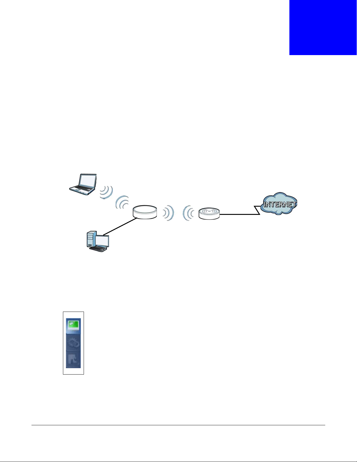
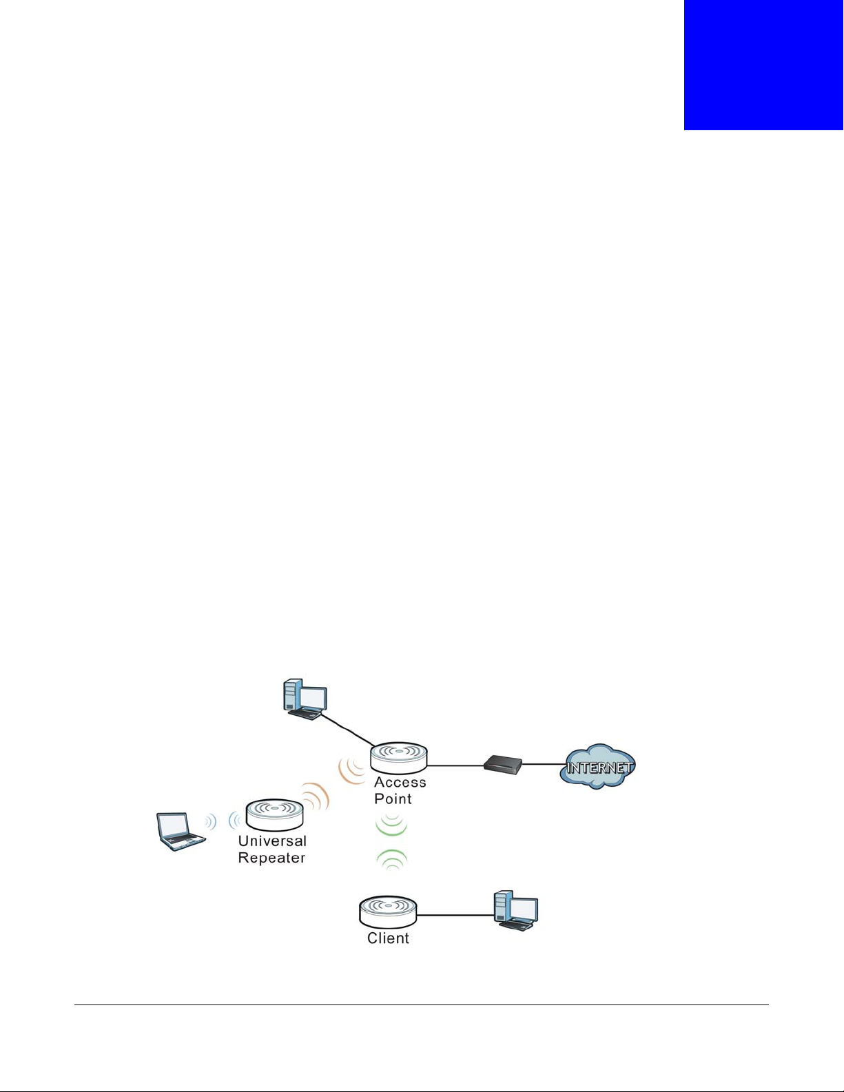
The ZyXEL WRE6505 Wireless AC750 Range Extender allows you to easily extend existing 802.11
b/g/n/ac wireless networks fast and easy. WRE6505 directly into a power outlet and the LED signal
strength indicator allows you to determine the ideal installation location. The one-click Wi-Fi
Protected Setup (WPS Button on page 12) provides frustration-free wireless client setup and
completes the instant network access setup.
Figure 1 Universal Repeater
CHAPTER 1
Introduction
Your can create the following connections using the WRE6505:
• LAN. You can connect network devices via the Ethernet port of the WRE6505 so that they can
communicate with each other and access the Internet.
• WLAN. Wireless clients can connect to the WRE6505 to access network resources.
Use a (supported) web browser to manage the WRE6505.
See Chapter 7 on page 37 for more information.
WRE6505 User’s Guide
9
Page 10
Chapter 1 Introduction
ETH
ER
NET
O
N/O
F
F
A
P/Rep
eater
2.4G
5G
WPS Button
LEDs
Power Switch
Ethernet Port
AP / Repeater
Mode Switch
1.2 Securing the WRE6505
Do the following things regularly to make the WRE6505 more secure and to manage the WRE6505
more effectively.
• Change the password. Use a password that’s not easy to guess and that consists of different
types of characters, such as numbers and letters.
• Write down the password and put it in a safe place.
• Back up the configuration (and make sure you know how to restore it). Restoring an earlier
working configuration may be useful if the device becomes unstable or even crashes. If you
forget your password, you will have to reset the WRE6505 to its factory default settings. If you
backed up an earlier configuration file, you would not have to totally re-configure the WRE6505.
You could simply restore your last configuration.
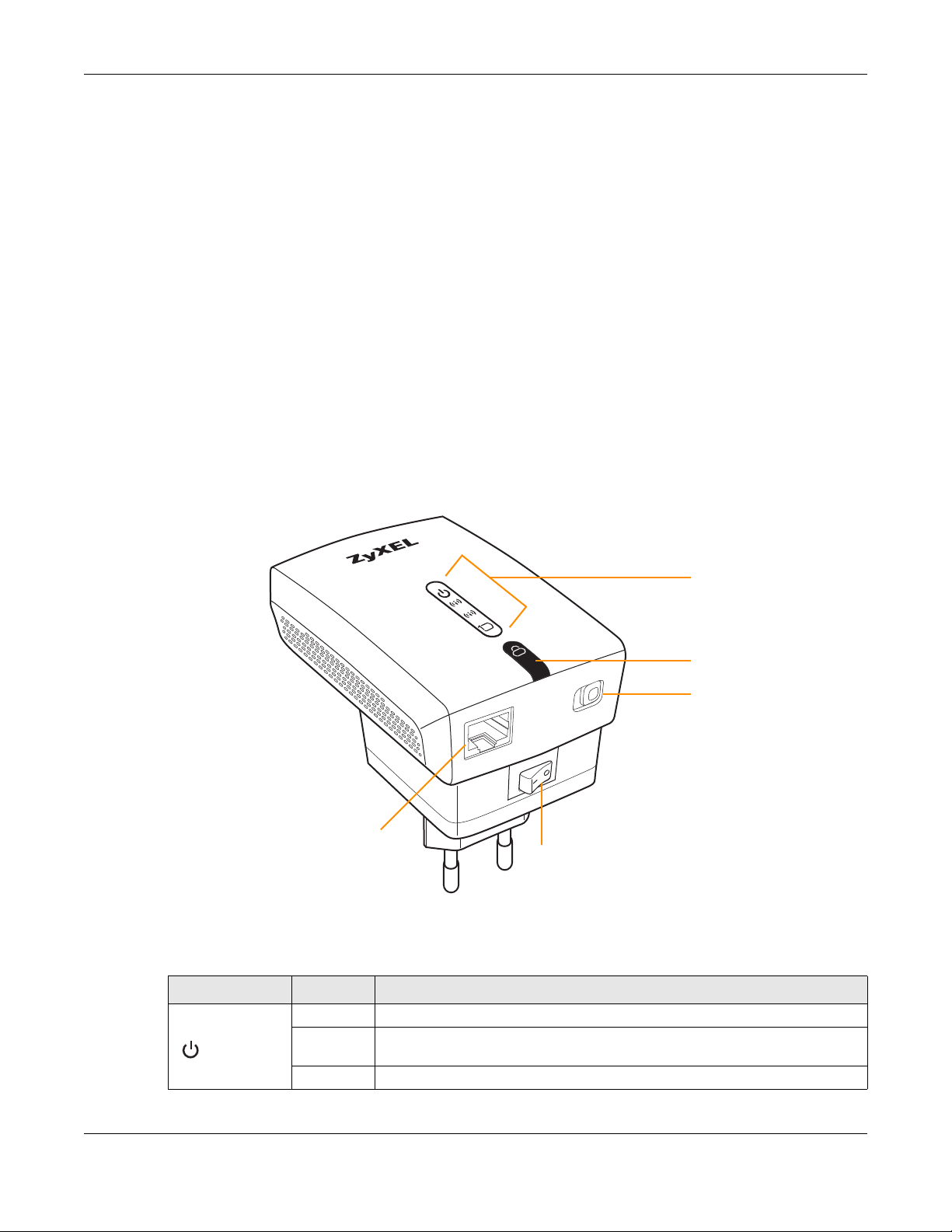
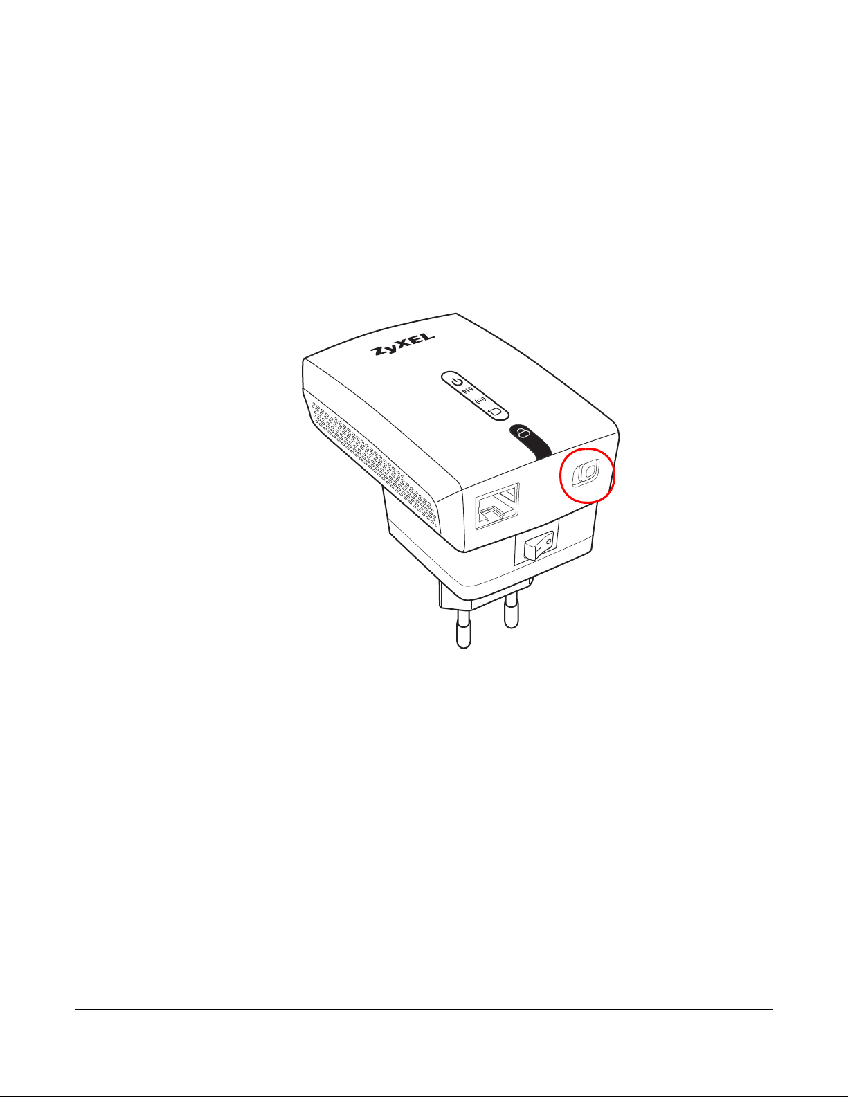
1.3 Front Panel
Figure 2 Front Panel
The following table describes the LEDs and the WPS button.
Table 1 Front Panel LEDs and WPS Button
LED STATUS DESCRIPTION
Power On (Green) The WRE6505 is receiving power and functioning properly.
Blinking
(Green)
Off The WRE6505 is not receiving power.
The WRE6505 is booting or resetting to factory defaults.
WRE6505 User’s Guide
10
Page 11
Chapter 1 Introduction
2.4G
5G5G
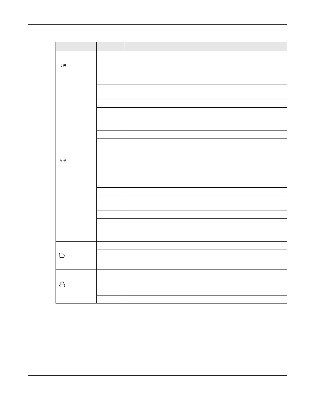
Table 1 Front Panel LEDs and WPS Button (continued)
LED STATUS DESCRIPTION
Wi-Fi 2.4G The device uses two LEDs to generate the following three signal colors:
2.4G
• Red: signifies a signal strength under 50%
• Orange: signifies a signal strength under 75%
• Green: signifies a signal strength over 75%
Repeater mode
On WLAN signal detected.
Blinking The WRE6505 is sending/receiving data through the wireless LAN.
Off The wireless LAN is not ready or fault detected.
AP mode
On WLAN is powered on.
Blinking The WRE6505 is sending/receiving data through the wireless LAN.
Off WLAN is off.
Wi-Fi 5G The device uses two LEDs to generate the following three signal colors:
• Red: signifies a signal strength under 50%
• Orange: signifies a signal strength under 75%
• Green: signifies a signal strength over 75%
Repeater mode
On WLAN signal detected.
Blinking The WRE6505 is sending/receiving data through the wireless LAN.
Off The wireless LAN is not ready or fault detected.
AP mode
On WLAN is powered on.
Blinking The WRE6505 is sending/receiving data through the wireless LAN.
Off WLAN is off.
LAN On (Green) The WRE6505 has a successful 10/100MB LAN connection.
Blinking
(Green)
Off Link is off.
WPS On (Blue) This remains on for 5 minutes after a successful WPS connection has been
Blinking
(Blue)
Off There is no WPS connection established.
The WRE6505 is transmitting data.
established.
The WRE6505 is waiting for another WPS device to connect.
WRE6505 User’s Guide
11
Page 12

1.4 WPS Button
The WPS button can be used to begin Wi-Fi Protected Setup (WPS), reboot the WRE6505 while
keeping it’s configuration or reboot the WRE6505 to factory default configuration.
Table 2 WPS Button Functions
ACTION RESULT
Push once or hold for
less than 5 seconds
AP Mode
Hold for 5 to 10
seconds
Hold for more than 10
seconds
Repeater Mode
Push twice The WRE6505 begins connecting to a wireless client via WPS. See
Hold for 5 to 10
seconds
Hold for more than 10
seconds
Chapter 1 Introduction
AP Mode:
Press (less than five seconds) to connect to a client. See Section
1.4 on page 12.
Repeater mode:
Press (less than five seconds) to enable WPS. Press twice to
connect to a client. See Section 1.4 on page 12.
The WRE6505 resets its configuration to factory defaults and
reboots. See Section 5.3 on page 28.
The WRE6505 keeps its configuration and reboots.
Section 1.4 on page 12.
The WRE6505 resets its configuration to factory defaults and
reboots. See Section 5.3 on page 28.
The WRE6505 keeps its configuration and reboots.
1.4.1 Wi-Fi Protected Setup
Your WRE6505 supports Wi-Fi Protected Setup (WPS), which is an easy way to set up a secure
wireless network. WPS is an industry standard specification, defined by the Wi-Fi Alliance.
WPS allows you to quickly set up a wireless network with strong security, without having to
configure security settings manually. Each WPS connection works between two devices. Both
devices must support WPS (check each device’s documentation to make sure).
Depending on the devices you have, you can either press a button (recommended) on the device
itself, or in its configuration utility or enter a PIN (a unique Personal Identification Number that
allows one device to authenticate the other) in each of the two devices. When WPS is activated on
a device, it has two minutes to find another device that also has WPS activated. Then, the two
devices connect and set up a secure network by themselves.
For more information on using WPS, see
Section 3.5 on page 19.
WRE6505 User’s Guide
12
Page 13
2.1 Overview
This chapter introduces the different modes available on your WRE6505.
• Sys OP mode. This is the operating mode of your WRE6505, or simply how the WRE6505 is
being used in the network.
2.1.1 Device Modes
This refers to the operating mode of the WRE6505, which can act as a:
• Universal Repeater: In this mode, the WRE6505 can be an access point and a wireless client at
the same time. Go to Section 3.4 on page 16 to view the Status screen in this mode. Use this
mode if there is an existing wireless router or access point in your network and you also want to
allow clients to connect to the WRE6505 wirelessly.
• Access Point: Use this mode if you want to extend your network by allowing network devices to
connect to the WRE6505 wirelessly. Go to Section 4.4 on page 22 to view the Status screen in
this mode.
In this mode, you can also set the WRE6505 to work as an AP only, a wireless bridge to establish
wireless links with other APs (WDS bridge), or an AP and bridge simultaneously (WDS repeater).
See Section 4.2 on page 21 for more information.
CHAPTER 2
WRE6505 Modes
The following figure is an illustration of the device configuration modes of the WRE6505.
Figure 3 Device Mode Example
Note: Choose your device mode carefully to avoid having to change it later.
WRE6505 User’s Guide
13
Page 14
Under Repeater mode, the WRE6505 supports three WPS behaviors: Normal mode, Range boost
ETH
ER
NET
O
N/O
F
F
A
P/Rep
eater
2.4G
5G
mode, and Speed boost mode. These behaviors are only available in Repeater mode through the
Maintenance screen.
2.1.1.1 Changing Operating Mode
Push the AP / Repeater mode switch on the WRE6505’s bottom panel to the AP position to have
the WRE6505 act as an access point. Push the switch to the Repeater position to have the
WRE6505 work as a universal repeater.
The WRE6505 restarts automatically after you change operating modes.
Figure 4 Bottom Panel
Chapter 2 WRE6505 Modes
WRE6505 User’s Guide
14
Page 15
3.1 Overview
A
B
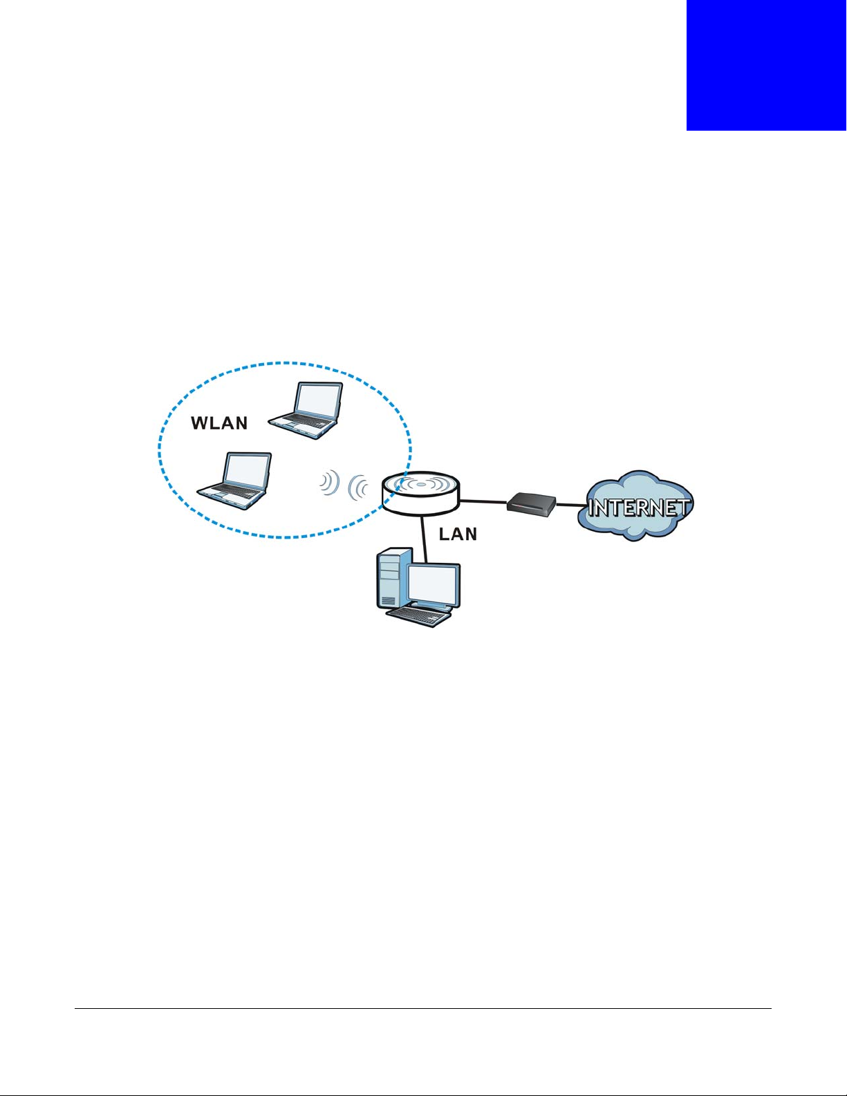
In universal repeater mode, your WRE6505 can act as an access point and wireless client at the
same time. The WRE6505 can connect to an existing network through another access point and
also lets wireless clients connect to the network through it. This helps you expand wireless
coverage when you have an access point or wireless router already in your network.
In the example below, the WRE6505 (A) is configured as a universal repeater. It has three clients
that want to connect to the Internet. The WRE6505 wirelessly connects to the available access point
(B).
Figure 5 Universal Repeater Mode
CHAPTER 3
Universal Repeater Mode
After the WRE6505 and the access point connect, the WRE6505 acquires its IP address from the
access point. The clients of the WRE6505 can now surf the Internet.
3.2 What You Can Do
•Use the Status screen (Section 7.1 on page 37) to view read-only information about your
WRE6505.
•Use the LAN screen (Chapter 10 on page 63) to set the IP address for your WRE6505.
•Use the Wireless LAN > WPS screen (Section 3.5 on page 19) to configure WPS on the
WRE6505 to associate to another access point.
•Use the Network > Wireless LAN (2.4G/5G) > Security screen (Section 9.5 on page 56) to
configure the wireless security between the WRE6505 and another access point.
•Use other Wireless LAN screens (Section 9.4 on page 55) to configure the wireless settings and
wireless security between the wireless clients and the WRE6505.
WRE6505 User’s Guide
15
Page 16

Chapter 3 Universal Repeater Mode
3.3 What You Need to Know
With the exception of the System Mode other configuration screens in Universal Repeater mode
are similar to the ones in Access Point Mode. See Chapter 2 on page 13 of this User’s Guide.
3.3.1 Setting your WRE6505 to Universal Repeater Mode
1 To use your WRE6505 as a universal repeater, see Section 2.1.1.1 on page 14.
2 Connect your computer to the LAN port of the WRE6505.
3 The default IP address of the WRE6505 is “192.168.1.2”. In this case, your computer must have an
IP address in the range between “192.168.1.3” and “192.168.1.254”.
4 After you’ve set your computer’s IP address, open a web browser such as Internet Explorer and
type “http://192.168.1.2” or http://zyxelsetup as the web address in your web browser.
5 Enter “1234” (default) as the password and click Login.
6 Type a new password and retype it to confirm, then click Apply. Otherwise, click Ignore.
Note: You have to log in to the Web Configurator again when you change modes. As soon
as you do, your WRE6505 is already in Universal Repeater mode.
Note: The universal repeater mode IP address is always the same as the access point
mode IP address. If you changed the IP address of your WRE6505 while in access
point mode, use this IP address in universal repeater mode.
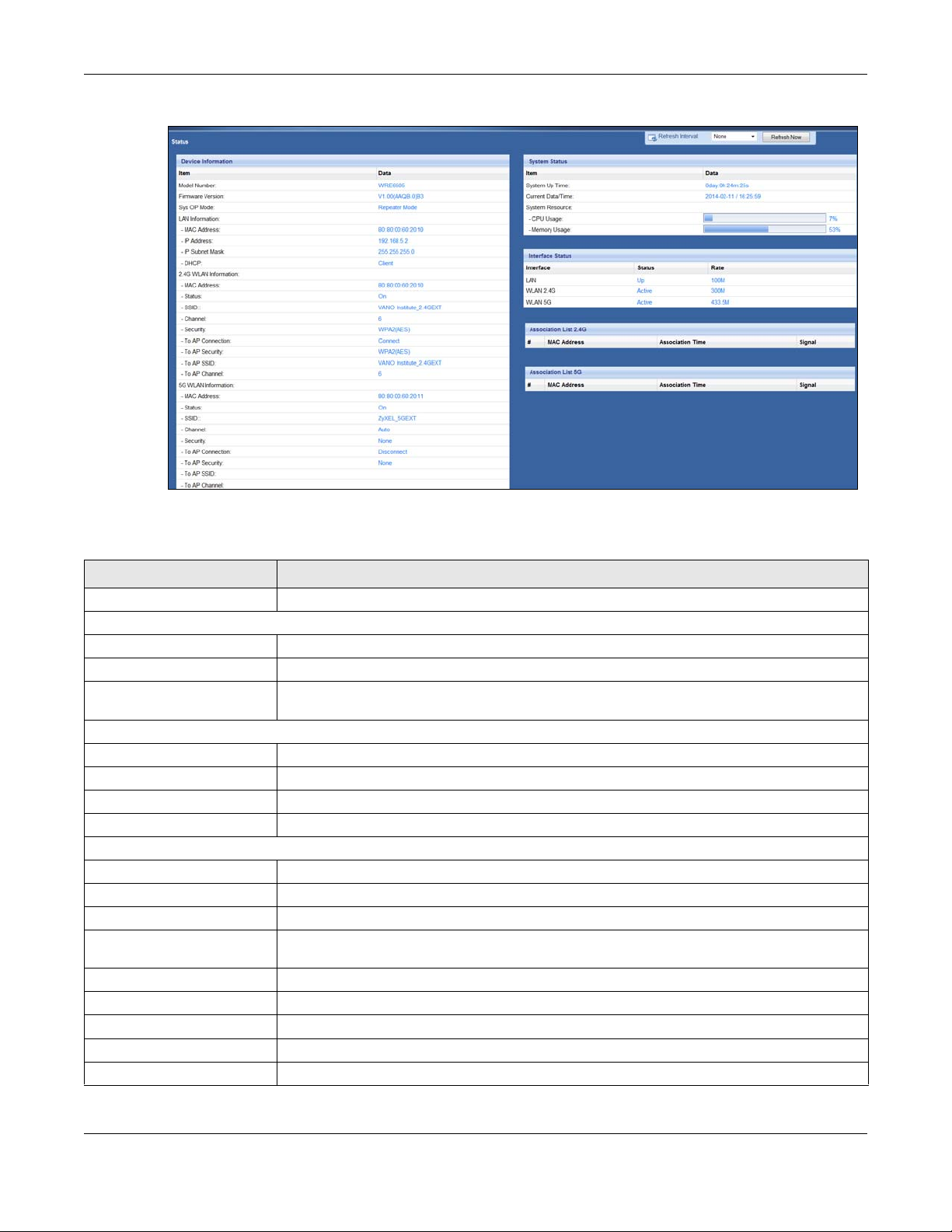
3.4 Universal Repeater Mode Status Screen
Click to open the Status screen.
WRE6505 User’s Guide
16
Page 17
Chapter 3 Universal Repeater Mode
Figure 6 Status: Universal Repeater Mode
The following table describes the labels shown in the Status screen.
Table 3 Status Screen: Universal Repeater Mode
LABEL DESCRIPTION
Logout Click this at any time to exit the Web Configurator.
Device Information
Model Number This is the WRE6505’s model name.
Firmware Version This is the firmware version and the date created.
Sys OP Mode This is the device mode (Section 2.1.1 on page 13) to which the WRE6505 is set - Universal
LAN Information
MAC Address This shows the LAN Ethernet adapter MAC Address of your device.
IP Address This shows the LAN port’s IP address.
IP Subnet Mask This shows the LAN port’s subnet mask.
DHCP This shows the LAN port’s DHCP role - Client or None.
2.4G WLAN Information
MAC Address This shows the wireless adapter MAC Address of your WRE6505.
Status This shows the current status of the Wireless LAN - ON.
SSID This shows a descriptive name used to identify the WRE6505 in the wireless LAN.
Channel This shows the channel number which you select manually or the WRE6505 automatically
Security This shows the level of wireless security the WRE6505 is using.
To AP Connection This displays whether the WRE6505 is connected to an AP or not.
To AP Security This displays the type of established security protocol with the AP.
To AP SSID This displays the SSID of the connected AP.
To AP Channel This displays the current channel in use with the connected AP.
Repeater Mode.
scans and selects.
WRE6505 User’s Guide
17
Page 18

Chapter 3 Universal Repeater Mode
Table 3 Status Screen: Universal Repeater Mode
LABEL DESCRIPTION
5G WLAN Information
MAC Address This shows the wireless adapter MAC Address of your WRE6505.
Status This shows the current status of the Wireless LAN - ON.
SSID This shows a descriptive name used to identify the WRE6505 in the wireless LAN.
Channel This shows the channel number which you select manually or the WRE6505 automatically
scans and selects.
Security This shows the level of wireless security the WRE6505 is using.
To AP Connection This displays whether the WRE6505 is connected to an AP or not.
To AP Security This displays the type of established security protocol with the WRE6505.
To AP SSID This displays the SSID of the connected AP.
To AP Channel This displays the current channel in use with the connected AP.
System Status
Item This column shows the type of data the WRE6505 is recording.
Data This column shows the actual data recorded by the WRE6505.
System Up Time This is the total time the WRE6505 has been on.
Current Date/Time This field displays your WRE6505’s present date and time.
System Resource
CPU Usage This displays what percentage of the WRE6505’s processing ability is currently used. When
this percentage is close to 100%, the WRE6505 is running at full load, and the throughput is
not going to improve anymore. If you want some applications to have more throughput, you
should turn off other applications (for example, using bandwidth management.
Memory Usage This shows what percentage of the heap memory the WRE6505 is using.
Interface Status
Interface This displays the WRE6505 port types. The port types are: LAN and WLAN.
Status For the LAN port, this field displays Down (line is down) or Up (line is up or connected).
For the WLAN, it displays Up when the WLAN is enabled or Down when the WLAN is
disabled.
Rate For the LAN ports, this displays the port speed and duplex setting or NA when the line is
disconnected.
For the WLAN, it displays the maximum transmission rate when the WLAN is enabled and NA
when the WLAN is disabled or Auto.
Association List 2.4G
# This is the index number of an associated wireless station.
MAC Address This field displays the MAC address of an associated wireless station.
Association Time This field displays the time a wireless station first associated with the WRE6505’s WLAN
network.
Signal This is the signal strength number of the associated client.
Association List 5G
# This is the index number of an associated wireless station.
MAC Address This field displays the MAC address of an associated wireless station.
Association Time This field displays the time a wireless station first associated with the WRE6505’s WLAN
Signal This is the signal strength number of the associated client.
network.
WRE6505 User’s Guide
18
Page 19
3.5 WPS Screen
Use this screen to connect to another AP. Go to Configuration > Wireless LAN (2.4G/5G) >
WPS to open the following screen.
Note: Wireless clients cannot use WPS to set up a wireless network with the WRE6505 in
universal repeater mode.
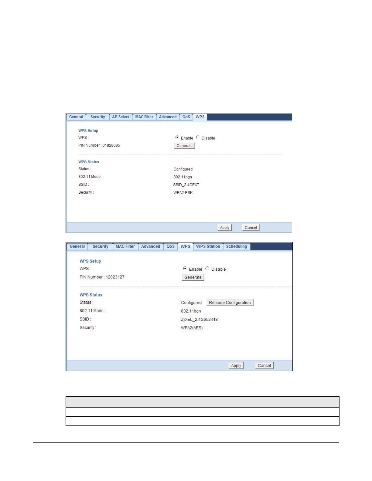
Figure 7 Universal Repeater: Configuration > Wireless LAN (2.4G/5G) > WPS
Chapter 3 Universal Repeater Mode
Figure 8 AP: Configuration > Wireless LAN (2.4G/5G) > WPS
The following table describes the labels in this screen.
Table 4 Universal Repeater: Configuration> Wireless LAN (2.4G / 5G) > WPS
LABEL DESCRIPTION
WPS Setup
WPS Select this to enable the WPS feature.
WRE6505 User’s Guide
19
Page 20

Chapter 3 Universal Repeater Mode
Table 4 Universal Repeater: Configuration> Wireless LAN (2.4G / 5G) > WPS (continued)
LABEL DESCRIPTION
PIN Number This displays a PIN number last time system generated. Click Generate to generate a new
PIN number.
Generate Click Generate to have the WRE6505 generate a PIN number.
WPS Status
Status This displays Configured when the WRE6505 has connected to a wireless network using
WPS or when Enable WPS is selected and wireless or wireless security settings have been
changed. The current wireless and wireless security settings also appear in the screen.
This displays Unconfigured if WPS is disabled and there are no wireless or wireless
security changes on the WRE6505 or you click Release Configuration to remove the
configured wireless and wireless security settings.
Release
Configuration
(AP Mode Only)
802.11 Mode Displays the wireless protocol configured for the WPS connection.
SSID Displays the network name for the WPS connection.
Security Displays the security protocol selected for the WPS connection.
Apply Click Apply to save your changes back to the WRE6505.
Cancel Click Cancel to return to the previous menu without saving.
This button is only available in AP mode when the WPS status displays Configured.
Click this button to remove all configured wireless and wireless security settings for WPS
connections on the WRE6505.
WRE6505 User’s Guide
20
Page 21
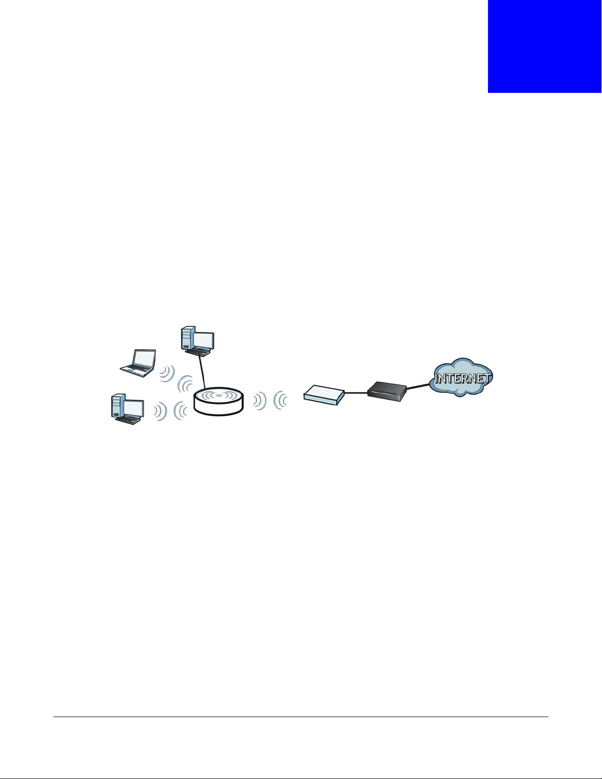
4.1 Overview
In Access Point (AP) mode your WRE6505 bridges a wired network (LAN) and wireless LAN (WLAN)
in the same subnet. See the figure below for an example.
Figure 9 Wireless Internet Access in Access Point Mode
CHAPTER 4
Access Point Mode
Note: See Chapter 8 on page 43 for an example of setting up a wireless network in
Access Point mode.
4.2 What You Can Do
•Use the Status screen (Section 4.4 on page 22) to view read-only information about your
WRE6505.
•Use the LAN screen (Chapter 10 on page 63) to set the IP address for your WRE6505 acting as
an access point.
•Use the Wireless LAN > WPS screen (Section 9.9 on page 59) to configure WPS on the
WRE6505 to associate to another access point.
WRE6505 User’s Guide
21
Page 22

Chapter 4 Access Point Mode
4.3 What You Need to Know
With the exception of the System Mode other configuration screens in Access Point mode are
similar to the ones in Universal Repeater mode. See Chapter 2 on page 13 of this User’s Guide.
4.3.1 Setting your WRE6505 to AP Mode
By default, AP mode in the WRE6505 is not configured with a static IP address. To setup your
WRE6505 in AP mode for the first time, the directly-connected router must have the DHCP server
function enabled.
1 To use your WRE6505 as an access point, set the mode switch to AP mode. See Section 2.1.1.1 on
page 14.
2 Connect one end of an Ethernet cable to the Ethernet port on the WRE6505 and the other end to
your router.
3 Connect your computer to your network, make sure both the WRE6505 and computer are under the
same subnet.
4 Open a web browser window and type “http://zyxelsetup” in the web address.
The login screen displays.
5 Enter “1234” (default) as the password and click Login.
6 Type a new password and retype it to confirm, then click Apply. Otherwise, click Ignore.
The WRE6505 Web Configurator displays, which allows you to configure the AP mode.
4.3.2 Configuring your WLAN, LAN and Maintenance Settings
•See Chapter 9 on page 53 and Chapter 10 on page 63 for information on the configuring your
wireless network and LAN settings.
•See Chapter 11 on page 65 for information on configuring your Maintenance settings.
4.4 AP Mode Status Screen
Click to open the Status screen.
WRE6505 User’s Guide
22
Page 23
Chapter 4 Access Point Mode
Figure 10 Status Screen: Access Point Mode
The following table describes the icons shown in the Status screen.
Table 5 Status Screen Icon Key: Access Point Mode
ICON DESCRIPTION
Click this icon to view copyright and a link for related product information.
Click this icon to open the wizard. See Chapter 6 on page 29.
Select a number of seconds or None from the drop-down list box to refresh all screen statistics
automatically at the end of every time interval or to not refresh the screen statistics.
Click this button to refresh the status screen statistics.
Click this icon to see the Status page. The information in this screen depends on the device
mode you select.
Click this icon to see the Configuration navigation menu.
Click this icon to see the Maintenance navigation menu.
The following table describes the labels shown in the Status screen.
Table 6 Status Screen: Access Point Mode
LABEL DESCRIPTION
Logout Click this at any time to exit the Web Configurator.
Device Information
Model Number This is the WRE6505’s model name.
Firmware Version This is the firmware version and the date created.
Sys OP Mode This is the device mode (Section 2.1.1 on page 13) to which the WRE6505 is set - Access
Point Mode.
LAN Information
MAC Address This shows the LAN Ethernet adapter MAC Address of your device.
IP Address This shows the LAN port’s IP address.
WRE6505 User’s Guide
23
Page 24

Chapter 4 Access Point Mode
Table 6 Status Screen: Access Point Mode (continued)
LABEL DESCRIPTION
IP Subnet Mask This shows the LAN port’s subnet mask.
DHCP This shows the LAN port’s DHCP role - Client or None.
2.4G WLAN Information
MAC Address This shows the wireless adapter MAC Address of your device.
Status This shows the current status of the Wireless LAN - ON.
SSID This shows a descriptive name used to identify the WRE6505 in the wireless LAN.
Channel This shows the channel number which you select manually or the WRE6505 automatically
scans and selects.
Security This shows the level of wireless security the WRE6505 is using.
5G WLAN Information
MAC Address This shows the wireless adapter MAC Address of your device.
Status This shows the current status of the Wireless LAN - ON.
SSID This shows a descriptive name used to identify the WRE6505 in the wireless LAN.
Channel This shows the channel number which you select manually or the WRE6505 automatically
scans and selects.
Security This shows the level of wireless security the WRE6505 is using.
System Status
Item This column shows the type of data the WRE6505 is recording.
Data This column shows the actual data recorded by the WRE6505.
System Up Time This is the total time the WRE6505 has been on.
Current Date/Time This field displays your WRE6505’s present date and time.
System Resource
CPU Usage This displays what percentage of the WRE6505’s processing ability is currently used. When
this percentage is close to 100%, the WRE6505 is running at full load, and the throughput is
not going to improve anymore. If you want some applications to have more throughput, you
should turn off other applications (for example, using bandwidth management.
Memory Usage This shows what percentage of the heap memory the WRE6505 is using.
Interface Status
Interface This displays the WRE6505 port types. The port types are: LAN and WLAN.
Status For the LAN port, this field displays Down (line is down) or Up (line is up or connected).
For the WLAN, it displays Up when the WLAN is enabled or Down when the WLAN is
disabled.
Rate For the LAN ports, this displays the port speed and duplex setting or NA when the line is
disconnected.
For the WLAN, it displays the maximum transmission rate when the WLAN is enabled and NA
when the WLAN is disabled or Auto.
Association List 2.4G
# This is the index number of an associated wireless client.
MAC Address This field displays the MAC address of an associated wireless client.
Association Time This field displays the time a wireless station first associated with the WRE6505’s WLAN
Signal This is the signal strength number of the associated client.
network.
WRE6505 User’s Guide
24
Page 25
Chapter 4 Access Point Mode
Table 6 Status Screen: Access Point Mode (continued)
LABEL DESCRIPTION
Association List 5G
# This is the index number of an associated wireless client.
MAC Address This field displays the MAC address of an associated wireless client.
Association Time This field displays the time a wireless station first associated with the WRE6505’s WLAN
network.
Signal This is the signal strength number of the associated client.
4.4.1 Navigation Panel
Use the menu in the navigation panel to configure WRE6505 features in Access Point mode.
The following screen and table show the features you can configure in Access Point mode.
Figure 11 Menu: Access Point Mode
The following table describes the sub-menus.
Table 7 Navigation Panel: Access Point Mode
LINK TAB FUNCTION
Status This screen shows the WRE6505’s general device, system and interface
CONFIGURATION
Network
Wireless LAN
2.4G
General Use this screen to configure general wireless LAN settings.
Security Use this screen to configure wireless security settings.
MAC Filter Use the MAC filter screen to configure the WRE6505 to block access to
Advanced This screen allows you to configure advanced wireless settings.
WPS Use this screen to configure WPS.
WPS Station Use this screen to add a wireless station using WPS. Only available in AP
Scheduling Use this screen to schedule the times the Wireless LAN is enabled.
status information. Use this screen to access the wizard, and summary
statistics tables.
devices or block the devices from accessing the WRE6505.
mode.
WRE6505 User’s Guide
25
Page 26

Chapter 4 Access Point Mode
Table 7 Navigation Panel: Access Point Mode
LINK TAB FUNCTION
Wireless LAN 5GGeneral Use this screen to configure general wireless LAN settings.
Security Use this screen to configure wireless security settings.
MAC Filter Use the MAC filter screen to configure the WRE6505 to block access to
devices or block the devices from accessing the WRE6505.
Advanced This screen allows you to configure advanced wireless settings.
WPS Use this screen to configure WPS.
WPS Station Use this screen to add a wireless station using WPS. Only available in AP
mode.
Scheduling Use this screen to schedule the times the Wireless LAN is enabled.
LAN IP Use this screen to configure LAN IP address and subnet mask.
MAINTENANCE
General Use this screen to view and change administrative settings such as system
Password Password
Setup
Time Time Setting Use this screen to change your WRE6505’s time and date.
Firmware
Upgrade
Backup/
Restore
Language Use this screen to select the language to display in the interface.
and domain names.
Use this screen to change the password of your WRE6505.
Use this screen to upload firmware to your WRE6505.
Use this screen to backup and restore the configuration or reset your
WRE6505 to the factory defaults.
WRE6505 User’s Guide
26
Page 27

5.1 Overview
This chapter describes how to access the WRE6505 Web Configurator and provides an overview of
its screens.
The Web Configurator is an HTML-based management interface that allows easy setup and
management of the WRE6505 via Internet browser. Use Internet Explorer 6.0 and later versions,
Mozilla Firefox 3 and later versions, or Safari 2.0 and later versions. The recommended screen
resolution is 1024 by 768 pixels.
In order to use the Web Configurator you need to allow:
• Web browser pop-up windows from your device. Web pop-up blocking is enabled by default in
Windows XP SP (Service Pack) 2.
• JavaScript (enabled by default).
• Java permissions (enabled by default).
CHAPTER 5
The Web Configurator
Refer to Chapter 12 Troubleshooting to see how to make sure these functions are allowed in
Internet Explorer.
5.2 Accessing the Web Configurator
1 Make sure your WRE6505 hardware is properly connected and prepare your computer or computer
network to connect to the WRE6505 (refer to the Quick Start Guide).
Note: If your computer is assigned a static IP address, it must be on the same subnet as
the WRE6505.
The WRE6505’s DHCP server is enabled before the WRE6505 is associated with
your AP or wireless router and disabled after association. If this is the first time you
are accessing your WRE6505, you can configure your computer as a DHCP client
(computer factory default) so it will get an IP address automatically from the
WRE6505. After the WRE6505 is associated with your wireless router, your
computer will get its IP address from the wireless router.
2 Launch your web browser.
3 If this is the first time you are accessing your WRE6505, type "http://192.168.1.2" as the website
address in your web browser. This is the default LAN IP address. Alternatively, after the WRE6505
has successfully associated with your wireless router, type "http://zyxelsetup" instead of the default
IP address.
WRE6505 User’s Guide
27
Page 28
Chapter 5 The Web Configurator
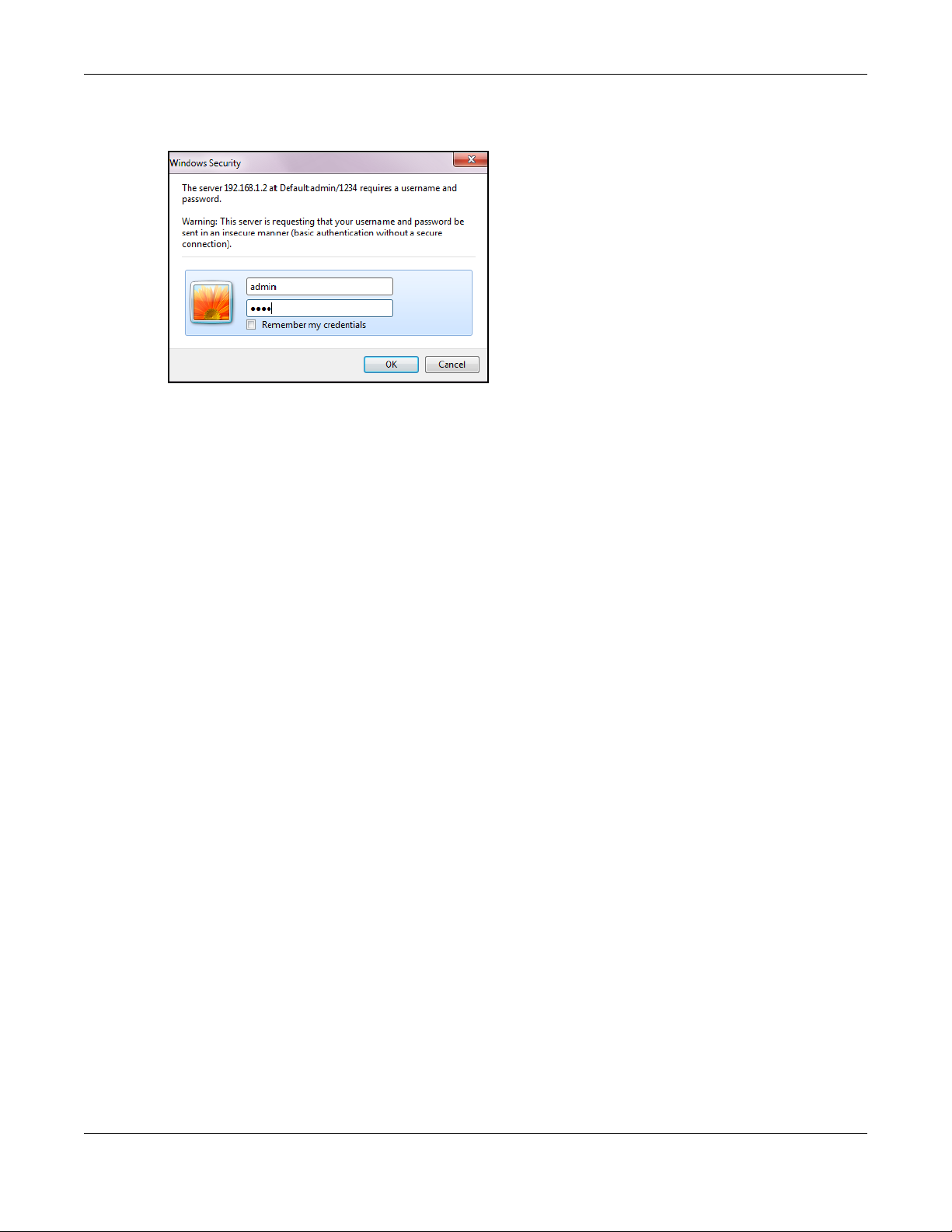
4 Type admin (default) as the user name and 1234 (default) as the password and click OK.
Figure 12 Login Screen
5.3 Resetting the WRE6505
If you forget your password or IP address, or you cannot access the Web Configurator, press the
WPS button for more than 5 seconds (no longer than 10 seconds) to reload the factory-default
configuration file. This means that you will lose all configurations that you had previously saved, the
username will be reset to admin and password will be reset to 1234. The IP address will be reset
to “192.168.1.2”.
1 Make sure the power LED is on.
2 Press and hold the WPS button. After 5 (no longer than 10) seconds, the power LED begins
flashing.
3 Release the WPS button. The WRE6505 reloads factory defaults and begins to reboot.
WRE6505 User’s Guide
28
Page 29
CHAPTER 6
Connection Wizard
6.1 Overview
This chapter provides information on the wizard setup screens in the Web Configurator.
The Web Configurator’s wizard setup helps you configure your device.
After you access the WRE6505 Web Configurator, click to start wizard setup.
6.2 Using the Web Configurator Wizard
The Web Configurator for the WRE6505 is available in Repeater and AP mode. The following section
reflects the web configuration process while in Repeater Mode.
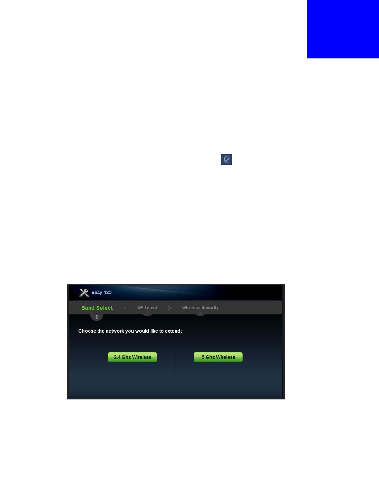
6.2.1 Extending the Network
The first step in setting up your network is to select the type of network to extend.
Click the 2.4 Ghz or 5 Ghz Wireless button to continue.
Figure 13 Wizard Step 1: Selecting Network
The wizard scans for available networks and displays the AP Select menu.
WRE6505 User’s Guide
29
Page 30
Chapter 6 Connection Wizard
6.2.2 Configuring the WRE6505 for Connection to an AP
In this step of the configuration wizard, you must configure the WRE6505 with the security
parameters of the AP you want to connect to. These parameters can be configured by selecting
those automatically detected by the WRE6505, or by configuring them manually. Manual
configuration is useful when the AP is hidden.
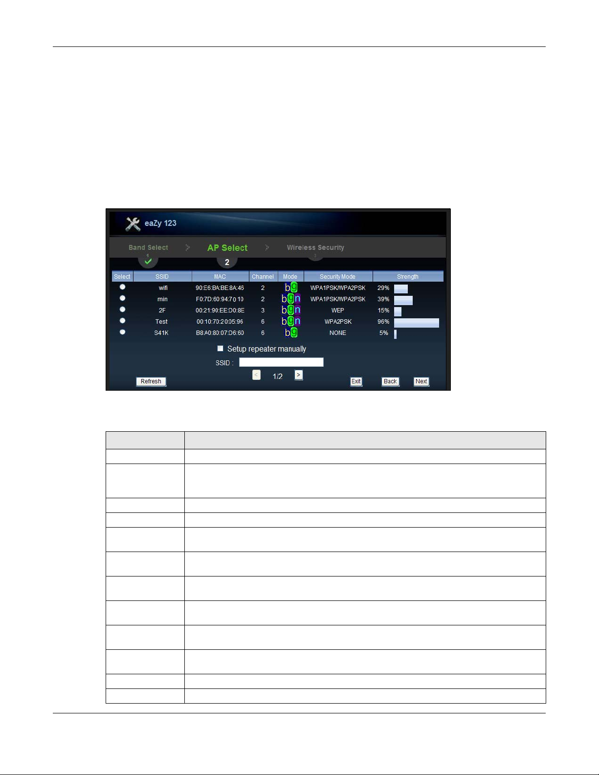
6.2.2.1 Selecting Automatically Detected AP Parameters
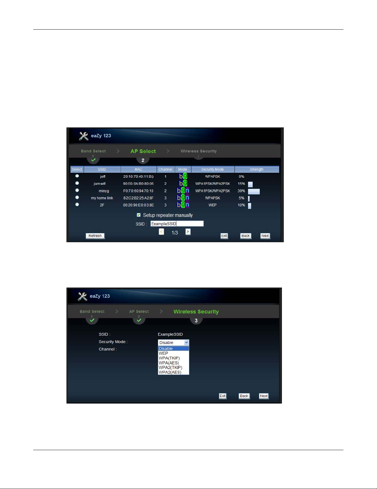
1 Select an available AP, see the following screen.
Figure 14 Wizard Step 2: Selecting an AP
The following table describes the labels in this screen.
Table 8 Network > Wireless LAN > AP Select
LABEL DESCRIPTION
Select Use the radio button to select the wireless device to which you want to connect.
SSID This displays the Service Set IDentity of the wireless device. The SSID is a unique name
that identifies a wireless network. All devices in a wireless network must use the same
SSID.
MAC This displays the MAC address of the wireless device.
Channel This displays the channel number used by this wireless device.
Mode This displays which IEEE 802.11b/g/n wireless networking standards the wireless device
Security Mode This displays the type of security configured on the wireless device. When no is shown, no
Strength This displays the strength of the wireless signal. The signal strength mainly depends on
Setup repeater
manually
SSID If Setup repeater manually is selected, use this field to type the SSID of the AP. This is
Refresh Click this to search for available wireless devices within transmission range and update
Back Click this to go back to the previous step in the wizard.
Next Click this to start the next step in the AP setup process.
supports.
security is configured and you can connect to it without a password.
the antenna output power and the distance between your WRE6505 and this device.
Select this to setup the AP manually. You will need to know the wireless router’s SSID.
This is the only option that allows you to manually set the channel.
useful when the AP’s SSID is hidden.
this table.
WRE6505 User’s Guide
30
Page 31

Chapter 6 Connection Wizard
Table 8 Network > Wireless LAN > AP Select (continued)
LABEL DESCRIPTION
Exit Click this to exit the wizard.
Previous Click this to see the previous page of APs.
Next Click this to see the next page of APs.
Note: The wireless stations and WRE6505 must use the same SSID, channel ID, WPA-PSK
(if WPA-PSK is enabled) or WPA2-PSK (if WPA2-PSK is enabled) for wireless
communication.
2 Click Next to continue.
3 Type the selected network’s wireless password (key). The number of characters accepted by the
KEY field is shown in the following table.
Figure 15 Wizard Step 3: Enter Wireless Network Password
The following table describes the labels in this screen.
Table 9 Maximum Key Lengths
ENCRYPTION KEY FORMAT KEY LENGTH
64-bit WEP ASCII 5 characters
Hex 10 characters
128-bit WEP ASCII 13 characters
Hex 26 characters
WPA pre-shared key Passphrase 8-63 characters
Hex 64 characters
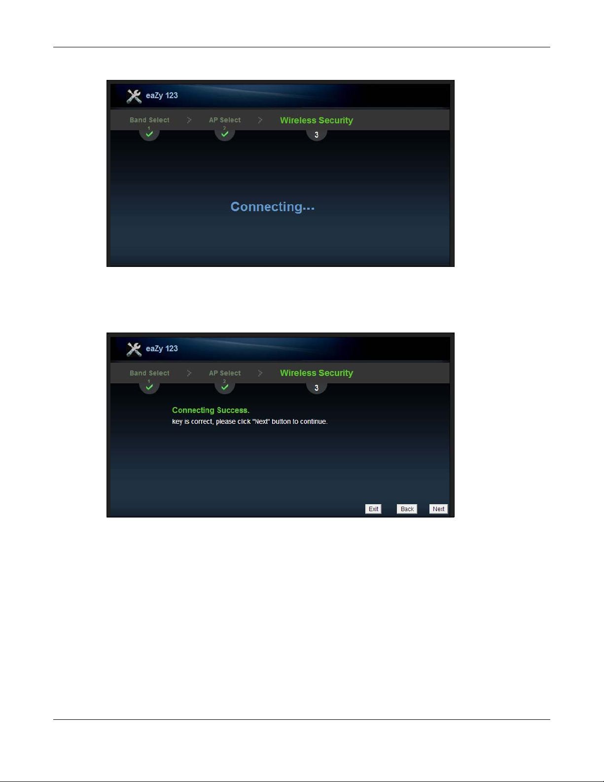
4 Click Next to continue and verify the password.
6.2.2.2 Completing the Connection Wizard
Complete the installation process by reviewing the wireless network settings and applying the
configuration.
After entering the wireless network’s password, the verification screen displays as follows.
WRE6505 User’s Guide
31
Page 32
Chapter 6 Connection Wizard
Figure 16 Wizard Step 3: Verifying the Password
The following screen appears if the key verifies successfully.
1 Click Next to continue. The Wireless Security overview page displays.
Figure 17 Wizard Step 4: Enter Wireless Network Password (Continued)
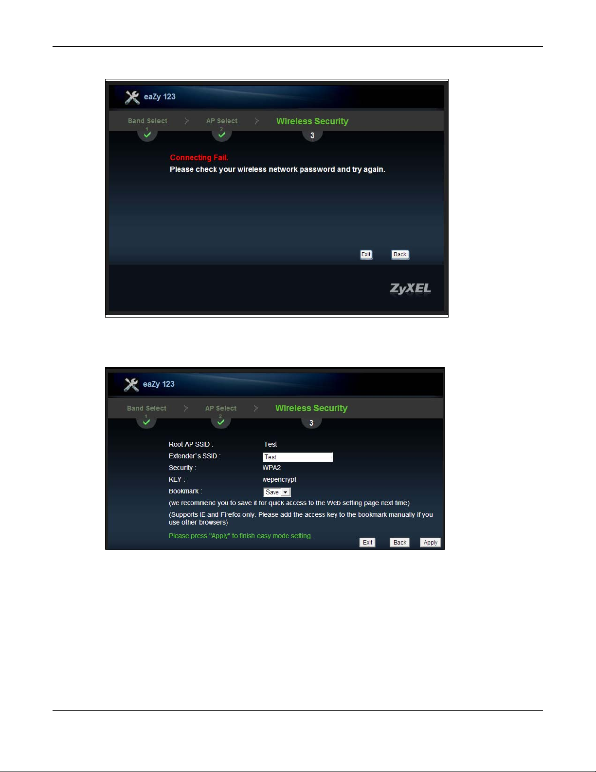
If the network password is invalid a pop-up and displays a connection failure. Click OK to return to
the network password page.
WRE6505 User’s Guide
32
Page 33
Chapter 6 Connection Wizard
Figure 18 Wizard Step 3: Key Verification Failed
2 Click Apply to complete the easy mode setting process, or click Back to return to the initial setup
screen. You can also click Exit to return to the main menu and exit the setup process.
Figure 19 Wizard Step 5: Verify Network Settings
3 Verify the selected wireless network settings. Click the Bookmark drop-down menu and select
Save to save the settings to your web browser’s cache. Select No to continue without saving. The
Bookmark function creates a bookmark in your browser and allows for quick access to web settings
the next time you log in.
Note: The Bookmark function is only supported by the following browsers: Microsoft
Internet Explorer and Mozilla Firefox.
A secondary 5 GHz setup screen displays. Click Yes to setup a 5 GHz network. Click No to restart
the device.
The eaZy 123 setup wizard is complete.
WRE6505 User’s Guide
33
Page 34
Chapter 6 Connection Wizard
6.2.2.3 Manually Configuring AP Parameters
If the AP you want to connect to is not listed, then follow these steps to configure the security
settings of the AP manually.
1 Select Setup repeater manually.
2 Type the SSID of the wireless router into the SSID field.
3 Click Next to continue.
Figure 20 Wizard Step 1: Entering the SSID
4 Select the security mode used by the wireless router from the drop-down menu.
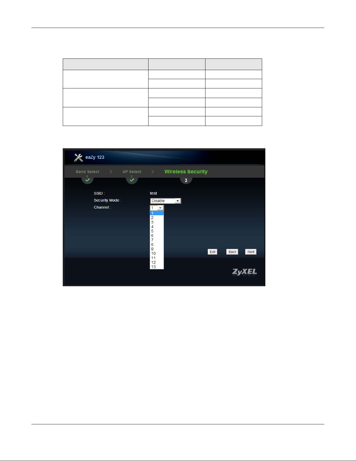
5 Configure the security settings. The number of characters accepted by the KEY field is shown in the
following table.
Figure 21 Wizard Step 2: Configuring Security Settings
WRE6505 User’s Guide
34
Page 35
Chapter 6 Connection Wizard
The following table describes the labels in this screen.
Table 10 Maximum Key Lengths
ENCRYPTION KEY FORMAT KEY LENGTH
64-bit WEP ASCII 5 characters
Hex 10 characters
128-bit WEP ASCII 13 characters
Hex 26 characters
WPA pre-shared key Passphrase 8-63 characters
Hex 64 characters
6 Select the channel from the drop-down menu.
Figure 22 Wizard Step 2: Configuring Security Settings
7 Click Next to continue.
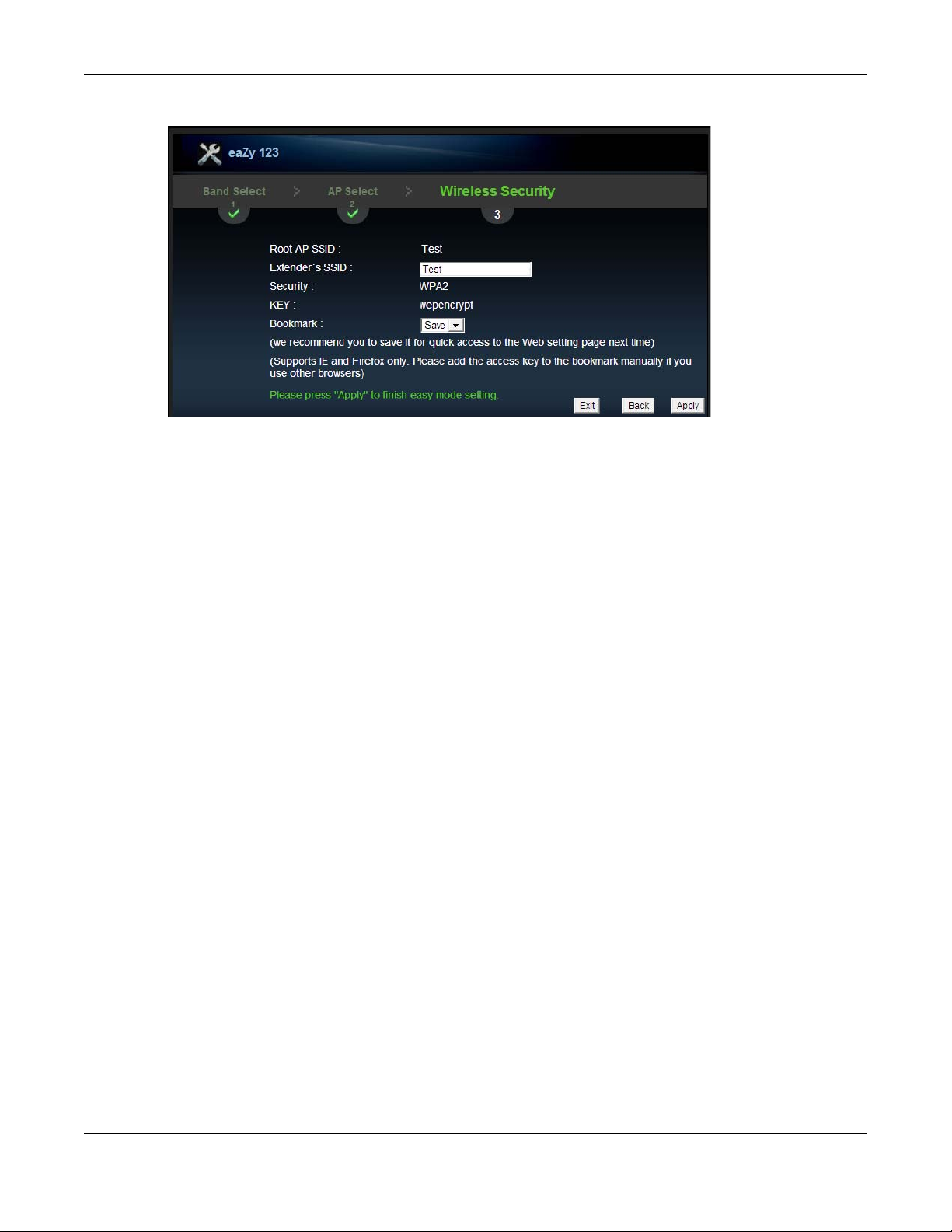
8 Click Apply to complete the easy mode setting process, or click Back to return to the initial setup
screen. You can also click Exit to return to the main menu and exit the setup process.
WRE6505 User’s Guide
35
Page 36
Chapter 6 Connection Wizard
Figure 23 Wizard Step 5: Verify Network Settings
9 Verify the selected wireless network settings. Click the Bookmark drop-down menu and select
Save to save the settings to your web browser’s cache. Select No to continue without saving. The
Bookmark function creates a bookmark in your browser and allows for quick access to web settings
the next time you log in.
Note: The Bookmark function is only supported by the following browsers: Microsoft
Internet Explorer and Mozilla Firefox (prior to version 23).
WRE6505 User’s Guide
36
Page 37
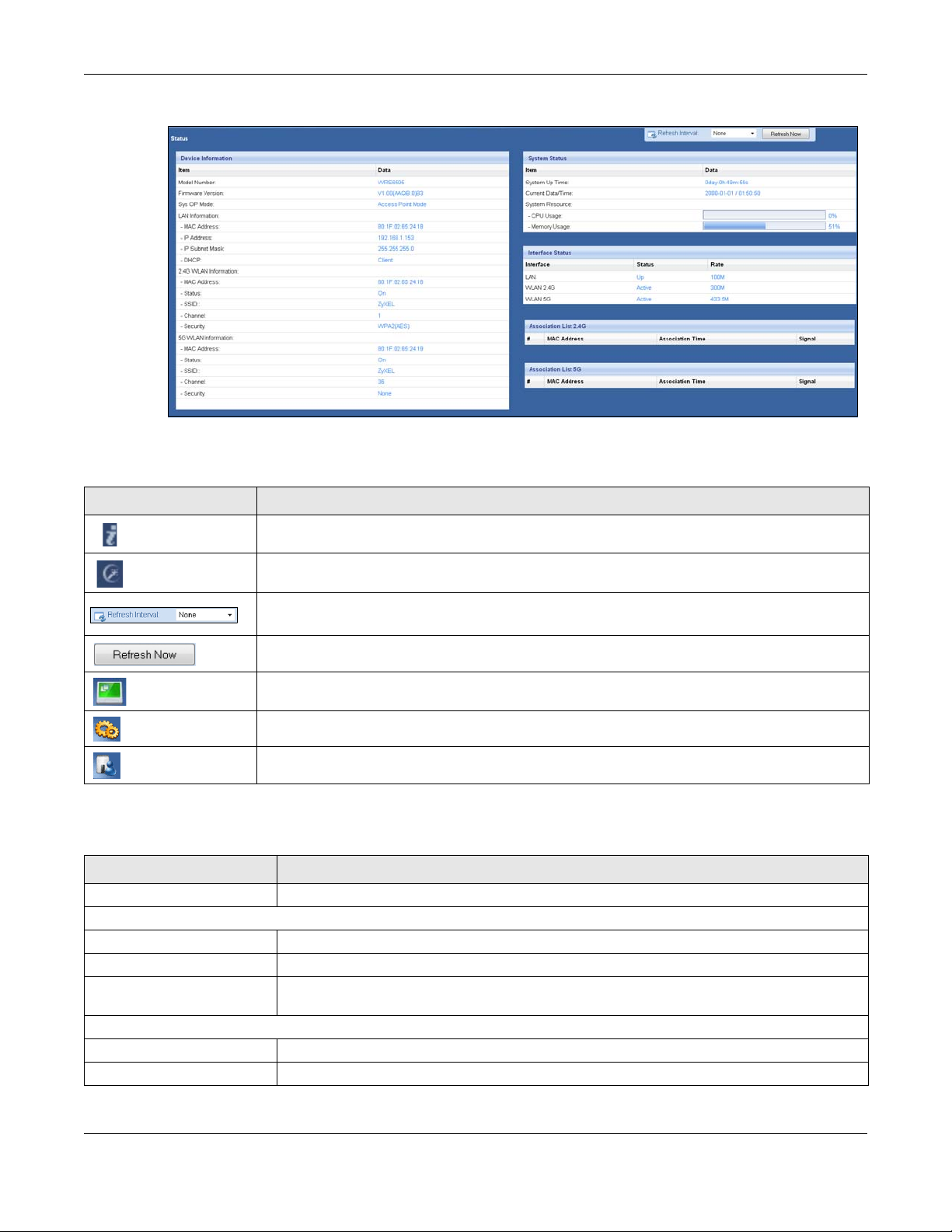
7.1 WRE6505 Status
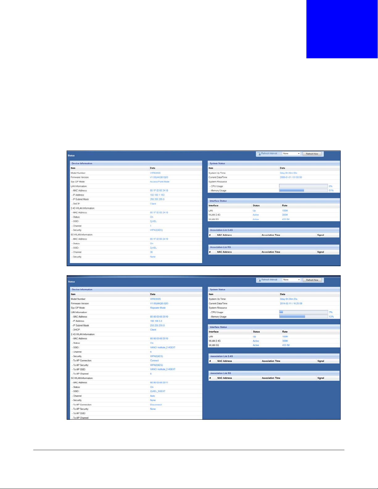
The screen below shows the status screen.
Figure 24 AP Mode > Status Screen
CHAPTER 7
Status
Figure 25 Repeat Mode > Status Screen
WRE6505 User’s Guide
37
Page 38
Chapter 7 Status
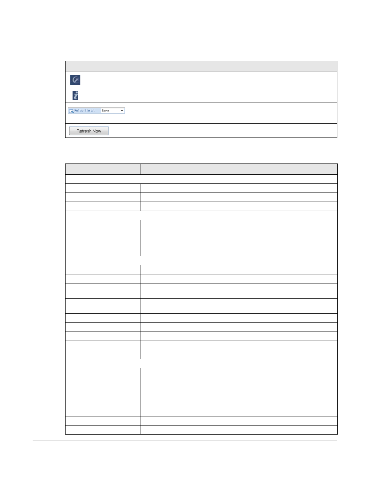
The following table describes the icons shown in the Status screen.
Tab le 11 Status Screen Icon Key
ICON DESCRIPTION
Click this icon to open the setup wizard.
Click this icon to view copyright and a link for related product information.
Select a number of seconds or None from the drop-down list box to refresh all
screen statistics automatically at the end of every time interval or to not refresh
the screen statistics.
Click this button to refresh the status screen statistics.
The following table describes the labels shown in the Status screen.
Table 12 Web Configurator Status Screen
LABEL DESCRIPTION
Device Information
Model Number This is the Model Number.
Firmware Version This is the current firmware version of the WRE6505.
Sys OP Mode This is the system’s current operating mode: AP or Repeater mode
LAN Information
- MAC Address This shows the LAN Ethernet adapter MAC Address of your device.
- IP Address This shows the LAN port’s IP address.
- IP Subnet Mask This shows the LAN port’s subnet mask.
- DHCP This shows the LAN port’s DHCP role.
2.4G WLAN Information
- MAC Address This shows the wireless adapter MAC Address of your device.
- Status This shows the current status of the Wireless LAN - On or Off.
- SSID This shows a descriptive name used to identify the WRE6505 in the wireless
LAN.
- Channel This shows the channel number which the WRE6505 is currently using over the
- Security This shows the level of wireless security the WRE6505 is using.
- To AP Connection This displays whether the WRE6505 is connected to an AP or not.
- To AP Security This displays the type of established security protocol with the device.
- To AP SSID This displays the SSID of the connected network router.
- To AP Channel This displays the current channel in use with the connected network router.
5G WLAN Information
- MAC Address This shows the wireless adapter MAC Address of your device.
- Status This shows the current status of the Wireless LAN - On or Off.
- SSID This shows a descriptive name used to identify the WRE6505 in the wireless
- Channel This shows the channel number which the WRE6505 is currently using over the
- Security This shows the level of wireless security the WRE6505 is using.
- To AP Connection This displays whether the WRE6505 is connected to an AP or not.
wireless LAN.
LAN.
wireless LAN.
WRE6505 User’s Guide
38
Page 39

Chapter 7 Status
Table 12 Web Configurator Status Screen (continued)
LABEL DESCRIPTION
- To AP Security This displays the type of established security protocol with the device.
- To AP SSID This displays the SSID of the connected network router.
- To AP Channel This displays the current channel in use with the connected network router.
System Status
System Up Time This is the total time the WRE6505 has been on.
Current Date/Time This field displays your WRE6505’s present date and time.
System Resource
- CPU Usage This displays what percentage of the WRE6505’s processing ability is currently
used. When this percentage is close to 100%, the WRE6505 is running at full
load, and the throughput is not going to improve anymore. If you want some
applications to have more throughput, you should turn off other applications.
- Memory Usage This shows what percentage of the heap memory the WRE6505 is using.
Interface Status
Interface This displays the WRE6505 port types. The port types are: LAN and WLAN.
Status For the LAN port, this field displays Down (line is down) or Up (line is up or
connected).
For the WLAN, it displays Up when the WLAN is enabled or Down when the
WLAN is disabled.
Rate For the LAN ports, this displays the port speed and duplex setting or NA when
the line is disconnected.
For the WLAN, it displays the maximum transmission rate when the WLAN is
enabled and NA when the WLAN is disabled or Auto.
Association List 2.4G
# This is the index number of an associated wireless client.
MAC Address This field displays the MAC address of an associated wireless client.
Association Time This field displays the time a wireless client is first associated with the
WRE6505’s WLAN network.
Signal This is the signal strength number of the associated client.
Association List 5G This table displays all the associated wireless clients and respective signal
# This is the index number of an associated wireless client.
MAC Address This field displays the MAC address of an associated wireless client.
Association Time This field displays the time a wireless client is first associated with the
Signal This is the signal strength number of the associated client.
strength.
WRE6505’s WLAN network.
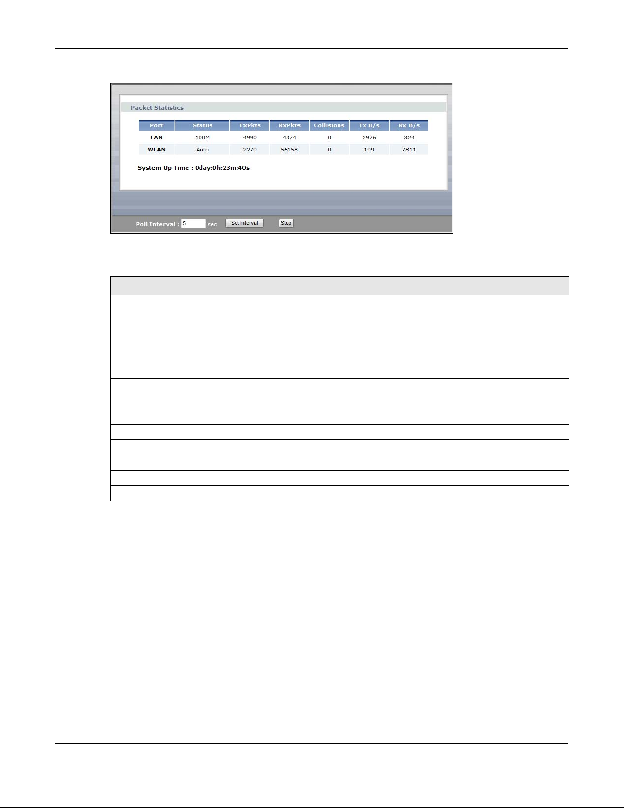
7.1.1 Summary: Packet Statistics
Click the Packet Statistics (Details...) hyperlink in the Status screen. Read-only information
here includes port status, packet specific statistics and the "system up time". The Poll Interval(s)
field is configurable and is used for refreshing the screen.
WRE6505 User’s Guide
39
Page 40
Chapter 7 Status
Figure 26 Summary: Packet Statistics
The following table describes the labels in this screen.
Table 13 Summary: Packet Statistics
LABEL DESCRIPTION
Port This is the WRE6505’s port type.
Status For the LAN ports, this displays the port speed and duplex setting or Down when the
line is disconnected.
For the WLAN, it displays Up when the WLAN is enabled or Down when the WLAN is
disabled or Auto.
TxPkts This is the number of transmitted packets on this port.
RxPkts This is the number of received packets on this port.
Collisions This is the number of collisions on this port.
Tx B/s This displays the transmission speed in bytes per second on this port.
Rx B/s This displays the reception speed in bytes per second on this port.
System Up Time This is the total time the WRE6505 has been on.
Poll Interval Enter the time interval for refreshing statistics in this field.
Set Interval Click this button to apply the new poll interval you entered in the Poll Interval field.
Stop Click Stop to stop refreshing statistics.
7.1.2 Summary: WLAN Station Status
Click the WLAN Station Status (Details...) hyperlink in the Status screen. View the wireless
stations that are currently associated to the WRE6505 in the Association List. Association means
that a wireless client (for example, your network or computer with a wireless network card) has
connected successfully to the AP (or wireless router) using the same SSID, channel and security
settings.
WRE6505 User’s Guide
40
Page 41

Chapter 7 Status
Figure 27 Summary: WLAN Station Status
The following table describes the labels in this screen.
Table 14 Summary: WLAN Station Status
LABEL DESCRIPTION
# This is the index number of an associated wireless station.
MAC Address This field displays the MAC address of an associated wireless station.
Association Time This field displays the time a wireless station first associated with the WRE6505’s WLAN
network.
Refresh Click Refresh to reload the list.
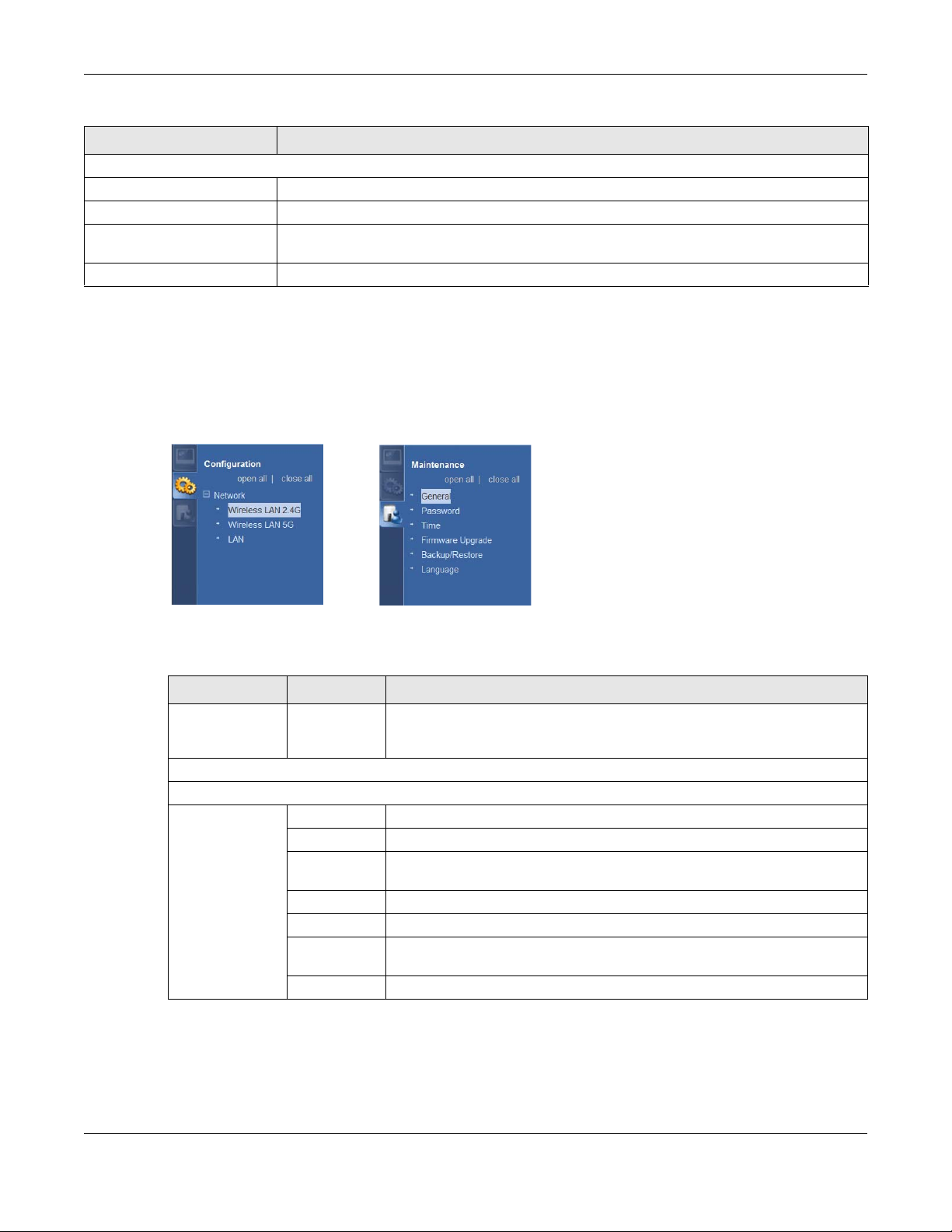
7.2 Navigation Panel
Use the menu in the navigation panel menus to configure WRE6505 features.
Figure 28 Menus
The following table describes the sub-menus.
Table 15 Menus
LINK TAB FUNCTION
Status This screen shows the WRE6505’s general device, system and interface
Configuration
status information. Use this screen to access the wizard, and summary
statistics tables.
WRE6505 User’s Guide
41
Page 42

Chapter 7 Status
Table 15 Menus (continued)
LINK TAB FUNCTION
Wireless
LAN 2.4G
Wireless
LAN 5G
LAN IP Use this screen to configure LAN IP address, subnet mask and gateway.
Maintenance
General Use this screen to configure wireless LAN.
Security Use this screen to select the available security modes as defined by the
paired AP or wireless router.
AP Select Use this screen to connect to an access point.
MAC Filter Use the MAC Address List screen to allow devices to access the WRE6505.
Advanced This screen allows you to configure advanced wireless settings.
WPS Use this screen to configure WPS.
WPS Station Use this screen to connect the WRE6505 to a wireless station or access
point using WPS.
General Use this screen to configure wireless LAN.
Security Use this screen to select the available security modes as defined by the
AP Select Use this screen to connect to an access point.
MAC Filter Use the MAC Address List screen to allow devices to access the WRE6505.
Advanced This screen allows you to configure advanced wireless settings.
WPS Use this screen to configure WPS.
WPS Station Use this screen to connect the WRE6505 to a wireless station or access
General This screen displays the system and domain names.
Password Use this screen to change the password.
Firmware
Upgrade
Backup/
Restore
Language Use this screen to select the language setting for the user interface.
System Mode Use this screen to select the WPS mode behavior.
paired AP or wireless router.
point using WPS.
Use this screen to upload firmware to your WRE6505.
Use this screen to backup and restore the configuration or reset the factory
defaults to your WRE6505.
WRE6505 User’s Guide
42
Page 43

CHAPTER 8
Tutorials
8.1 Overview
This chapter provides tutorials for your WRE6505 as follows (in access point or universal repeater
mode) as follows:
• Connecting to the Internet from an Access Point
• Connecting to a Wireless Network Using WPS
• Connecting the WRE6505 to an AP
8.2 Connecting to the Internet from an Access Point
This section gives you an example of how to set up an access point (AP) and wireless client (a
notebook (B), in this example) for wireless communication. B can access the Internet through the
access point (A) wirelessly.
Figure 29 Wireless Access Point Connection to the Internet
8.3 Connecting to a Wireless Network Using WPS
This section gives you an example of how to set up wireless network using WPS. The following
example uses the WRE6505 as the AP and NWD-211AN as the wireless client which connects to a
notebook.
Note: The wireless client must be a WPS-aware device (for example, a WPS USB adapter
or PCI card).
The following WPS methods for creating a secure connection are described in the tutorial.
• Push Button Configuration (PBC) - create a secure wireless network simply by pressing a
button. See Section 8.3.1 on page 44.This is the easier method.
WRE6505 User’s Guide
43
Page 44

Chapter 8 Tutorials
• PIN Configuration - create a secure wireless network simply by entering a wireless client's PIN
(Personal Identification Number) in the WRE6505’s interface. See Section 8.3.2 on page 45. This
is the more secure method, since one device can authenticate the other.
8.3.1 Push Button Configuration (PBC)
The push button configuration function found in the interface is only available in AP mode. The WPS
button, see Section 1.3 on page 10, can also be used for PBC configurations in either AP or
Repeater mode.
1 Make sure that your WRE6505 is turned on and set to work in AP mode and that it is connected to
your network.
2 Launch your wireless client’s configuration utility.
3 In the wireless client utility, find the WPS settings. Enable WPS and press the WPS button (Start or
WPS button).
4 Log into WRE6505’s Web Configurator. Make sure WPS is enabled in the Network > Wireless LAN
> WPS screen.
5 Navigate to Network > Wireless LAN > WPS Station and press the Push Button.
Note: Your WRE6505 has a WPS button located on its panel, as well as a WPS button in
its configuration utility (AP mode only). Both buttons have exactly the same
function; you can use one or the other.
Note: It doesn’t matter which button is pressed first. You must press the second button
within two minutes of pressing the first one.
The WRE6505 sends the proper configuration settings to the wireless client. This may take up to
two minutes. Then the wireless client is able to communicate with the WRE6505 securely.
The following figure shows you how to set up wireless network and security by pressing a button on
both WRE6505 and wireless client (the NWD-211AN in this example).
WRE6505 User’s Guide
44
Page 45

Chapter 8 Tutorials
2.4G2.4G
5G5G
Wireless Client
SECURITY INFO
COMMUNICATION
WITHIN 2 MINUTES
AP
2.4G2.4G
5G5G
2.4G
5G
2.4G2.4G
5G5G
2.4G2.4G
5G5G
Figure 30 Example WPS Process: PBC Method
8.3.2 PIN Configuration
1 Launch your wireless client’s configuration utility. Go to the WPS Station settings and select the PIN
2 On the WRE6505, navigate to the Network > Wireless LAN (2.4G/5G) > WPS screen.
3 Obtain the PIN number for the WRE6505 or press the Generate button to create a new PIN
4 Enter the WRE6505 PIN number in the wireless station’s utility screen.
When you use the PIN configuration method, you need to use both WRE6505’s configuration
interface and the client’s utilities.
The push button configuration function is only available in AP mode.
method to get a PIN number.
number. See Section 9.9 on page 59
The WRE6505 authenticates the wireless client and sends the proper configuration settings to the
wireless client. This may take up to two minutes. Then the wireless client is able to communicate
with the WRE6505 securely.
WRE6505 User’s Guide
45
Page 46

Chapter 8 Tutorials
Authentication by PIN
SECURITY INFO
WITHIN 2 MINUTES
Wireless Client
COMMUNICATION
2.4G
5G
2.4G
5G
2.4G
5G
2.4G
5G
2.4G
5G
The following figure shows an example of how to set up wireless network and security on WRE6505
and wireless client (ex. NWD210N in this example) by using PIN method.
Figure 31 Example WPS Process: PIN Method
2.4G
5G
2.4G
5G
8.4 Connecting the WRE6505 to an AP
2.4G
5G
2.4G
5G
2.4G
5G
Repeater mode allows you to extend the original AP coverage.
• Selecting an AP from an Automatically Detected List - create a secure wireless network
simply by selecting an AP from a list of detected APs. See Section 8.4.1 on page 47.This is the
easier method.
WRE6505 User’s Guide
46
Page 47

Chapter 8 Tutorials
• Selecting an AP by Manually Entering Security Information - create a secure wireless
network by manually entering the AP’s wireless security settings in the WRE6505’s interface. See
Section 8.4.2 on page 49. This is useful when the AP is hidden.
8.4.1 Selecting an AP from an Automatically Detected List
Follow the steps below to create a secure wireless network by selecting an AP from a list of detected
APs.
The AP select function is only available in repeater mode. See Section 2.1.1 on page 13.
The instructions require that your hardware is connected (see the Quick Start Guide) and you are
logged into the Web Configurator through your LAN connection (see Section 5.2 on page 27).
1 Select an AP form the Select column and click Next.
Figure 32 Tutorial: Selecting an automatically detected AP
2 Type a key into the KEY field and click Next.
Figure 33 Tutorial: The KEY field
3 Wait for the WRE6505 to verify the key with the AP.
WRE6505 User’s Guide
47
Page 48
Chapter 8 Tutorials
Figure 34 Tutorial: Verifying the key
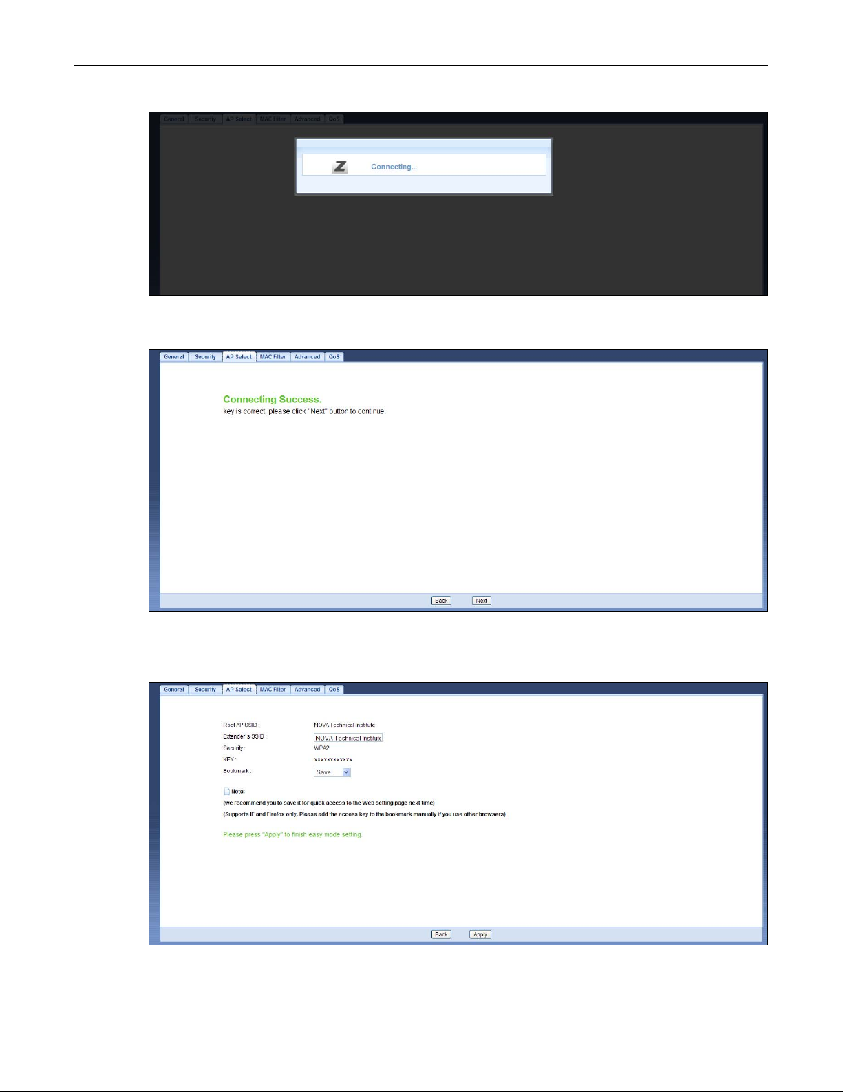
4 When the key is verified, click Next.
Figure 35 Tutorial: Successful key verification
5 Click APPLY to save settings and restart the WRE6505. Click CONTINUE to go to the Status
screen without saving the settings and restarting the WRE6505.
Figure 36 Tutorial: Saving settings
WRE6505 User’s Guide
48
Page 49

Chapter 8 Tutorials
8.4.2 Selecting an AP by Manually Entering Security Information
This example shows you how to configure wireless security settings with the following parameters
on your WRE6505.
SSID ExampleSSID
Channel 7
Security WPA2 PSK
Follow the steps below to create a secure wireless network by manually entering the AP’s wireless
security settings in the WRE6505’s interface.
The instructions require that your hardware is connected (see the Quick Start Guide) and you are
logged into the Web Configurator through your LAN connection (see Section 5.2 on page 27).
1 Select Setup repeater manually.
2 Type the SSID of the AP into the SSID field and click Next.
Figure 37 Tutorial: Typing an SSID
3 Select the security settings and click Next.
WRE6505 User’s Guide
49
Page 50

Chapter 8 Tutorials
Figure 38 Tutorial: Security Settings
4 Click Apply to save settings and restart the WRE6505. Click CONTINUE to go to the Status screen
without saving the settings and restarting the WRE6505.
Figure 39 Tutorial: Saving settings
WRE6505 User’s Guide
50
Page 51

PART II
Technical Reference
51
Page 52

52
Page 53

9.1 Overview
This chapter discusses how to configure the wireless network settings in your WRE6505. See
Section 1.1 on page 9 for an overview of wireless networks.
9.2 What You Can Do
•Use the General screen to enable the Wireless LAN (2.4G/5G), enter the SSID and select the
wireless security mode (Section 9.4 on page 55).
•Use the Security screen to (Section 9.5 on page 56).
•Use the MAC Filter screen to allow or deny wireless stations based on their MAC addresses from
connecting to the WRE6505 (Section 9.7 on page 57).
•Use the Advanced screen to allow intra-BSS networking and set the RTS/CTS Threshold (Section
9.8 on page 59).
•Use the WPS screen to quickly set up a wireless network with strong security, without having to
configure security settings manually (Section 9.9 on page 59).
•Use the AP Select screen to choose an access point that you want the WRE6505 to connect to.
You should know the security settings of the target AP (Section 9.6 on page 56).
CHAPTER 9
Wireless LAN
9.3 What You Should Know
Every wireless network must follow these basic guidelines.
• Every wireless client in the same wireless network must use the same SSID.
The SSID is the name of the wireless network. It stands for Service Set IDentity.
• If two wireless networks overlap, they should use different channels.
Like radio stations or television channels, each wireless network uses a specific channel, or
frequency, to send and receive information.
• Every wireless client in the same wireless network must use security compatible with the AP.
Security stops unauthorized devices from using the wireless network. It can also protect the
information that is sent in the wireless network.
9.3.1 Wireless Security Overview
The following sections introduce different types of wireless security you can set up in the wireless
network.
WRE6505 User’s Guide
53
Page 54

9.3.1.1 MAC Address List
Chapter 9 Wireless LAN
Every wireless client has a unique identification number, called a MAC address.1 A MAC address is
usually written using twelve hexadecimal characters
00:A0:C5:00:00:02. To get the MAC address for each wireless client, see the appropriate User’s
Guide or other documentation.
You can use the MAC Address List to tell the AP which wireless clients are allowed to use the
wireless network. If a wireless client is allowed to use the wireless network, it still has to have the
correct settings (SSID, channel, and security). If a wireless client is not allowed to use the wireless
network, it does not matter if it has the correct settings.
This type of security does not protect the information that is sent in the wireless network.
Furthermore, there are ways for unauthorized devices to get the MAC address of an authorized
wireless client. Then, they can use that MAC address to use the wireless network.
9.3.1.2 Encryption
Wireless networks can use encryption to protect the information that is sent in the wireless
network. Encryption is like a secret code. If you do not know the secret code, you cannot
understand the message.
Table 16 Types of Encryption for Each Type of Authentication
Weakest No Security
Strongest WPA2-PSK
NO AUTHENTICATION
Static WEP
WPA-PSK
2
; for example, 00A0C5000002 or
For example, if users do not log in to the wireless network, you can choose no authentication, if
users do log on to the wireless network, you can choose No Security, Static WEP, WPA-PSK, or
WPA2-PSK.
Usually, you should set up the strongest encryption that every wireless client in the wireless
network supports. Suppose the wireless network has two wireless clients. Device A only supports
WEP, and device B supports WEP and WPA-PSK. Therefore, you should set up Static WEP in the
wireless network.
Note: It is recommended that wireless networks use WPA-PSK, or stronger encryption.
IEEE 802.1x and WEP encryption are better than none at all, but it is still possible
for unauthorized devices to figure out the original information pretty quickly.
Many types of encryption use a key to protect the information in the wireless network. The longer
the key, the stronger the encryption. Every wireless client in the wireless network must have the
same key.
1. Some wireless devices, such as scanners, can detect wireless networks but cannot use wireless networks. These kinds
of wireless devices might not have MAC addresses.
2. Hexadecimal characters are 0, 1, 2, 3, 4, 5, 6, 7, 8, 9, A, B, C, D, E, and F.
WRE6505 User’s Guide
54
Page 55

Chapter 9 Wireless LAN
9.3.1.3 WPS
Wi-Fi Protected Setup (WPS) is an industry standard specification, defined by the Wi-Fi Alliance.
WPS allows you to quickly set up a wireless network with strong security, without having to
configure security settings manually. Depending on the devices in your network, you can either
press a button (on the device itself, or in its configuration utility) or enter a PIN (Personal
Identification Number) in the devices. Then, they connect and set up a secure network by
themselves. See how to set up a secure wireless network using WPS in the Section 8.3 on page 43.
9.4 General Wireless LAN Screen
Use this screen to enable the Wireless LAN, enter the SSID and select the wireless security mode.
Note: If you are configuring the WRE6505 from a computer connected to the wireless
LAN and you change the WRE6505’s SSID, channel or security settings, you will
lose your wireless connection when you press Apply to confirm. You must then
change the wireless settings of your computer to match the WRE6505’s new
settings.
Click Network > Wireless LAN (2.4G/5G) to open the General screen.
Figure 40 Network > Wireless LAN (2.4G/5G) > General
The following table describes the general wireless LAN labels in this screen.
Table 17 Network > Wireless LAN (2.4G/5G) > General
LABEL DESCRIPTION
Wireless Setup
Wireless LAN This is turned on by default. Click Disable to turn off the wireless LAN function.
Network Name
(SSID)
or
Name
(SSID1~3)
Hide Select this check box to hide the SSID in the outgoing beacon frame so a wireless client
Operating
Channel
The SSID (Service Set IDentity) identifies the Service Set with which a wireless client is
associated. Enter a descriptive name (up to 32 printable characters found on a typical
English language keyboard) for the wireless LAN.
You can configure up to two SSIDs to enable two BSSs (Basic Service Sets) on the WRE6505.
Wireless clients can use different SSIDs to associate with the same access point.
cannot obtain the SSID through scanning using a site survey tool.
This displays the channel the WRE6505 is currently using.
WRE6505 User’s Guide
55
Page 56
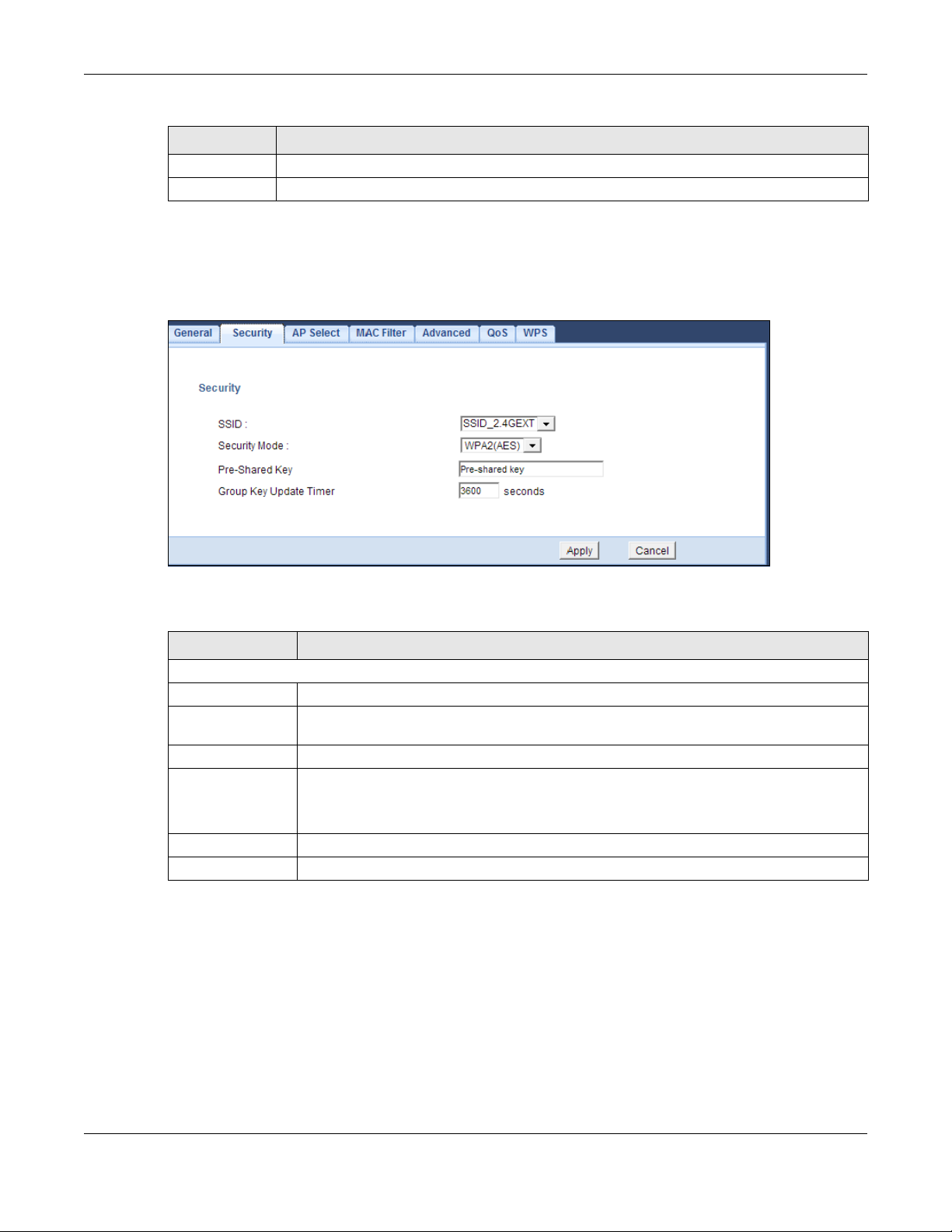
Table 17 Network > Wireless LAN (2.4G/5G) > General (continued)
LABEL DESCRIPTION
Apply Click Apply to save your changes back to the WRE6505.
Cancel Click Cancel to return to the previous menu without saving.
9.5 Security
Figure 41 Universal Repeater Mode: Wireless LAN (2.4G/5G) > Security
Chapter 9 Wireless LAN
The following table describes the labels in this screen.
Table 18 Universal Repeater Mode: Wireless LAN (2.4G/5G) > Security
LABEL DESCRIPTION
Security
SSID Enter the name of the access point to which you are connecting.
Security Mode Select No Security or the available modes to match as provided by the source AP or
wireless router.
Pre-Shared Key Enter the security pre-shared key as provided by the source AP or wireless router.
Group Key Update
Timer
Apply Click Apply to save your changes back to the WRE6505.
Cancel Click Cancel to reload the previous configuration for this screen.
The Group Key Update Timer is the rate at which the AP sends a new group key out to all
clients.
The default is 3600 seconds (60 minutes).
9.6 AP Select Screen
Use this screen (available in repeater mode only) to choose an access point that you want the
WRE6505 to connect to. You should know the security settings of the target AP.
To open this screen, click Network > Wireless LAN (2.4G/5G) > AP Select tab.
WRE6505 User’s Guide
56
Page 57
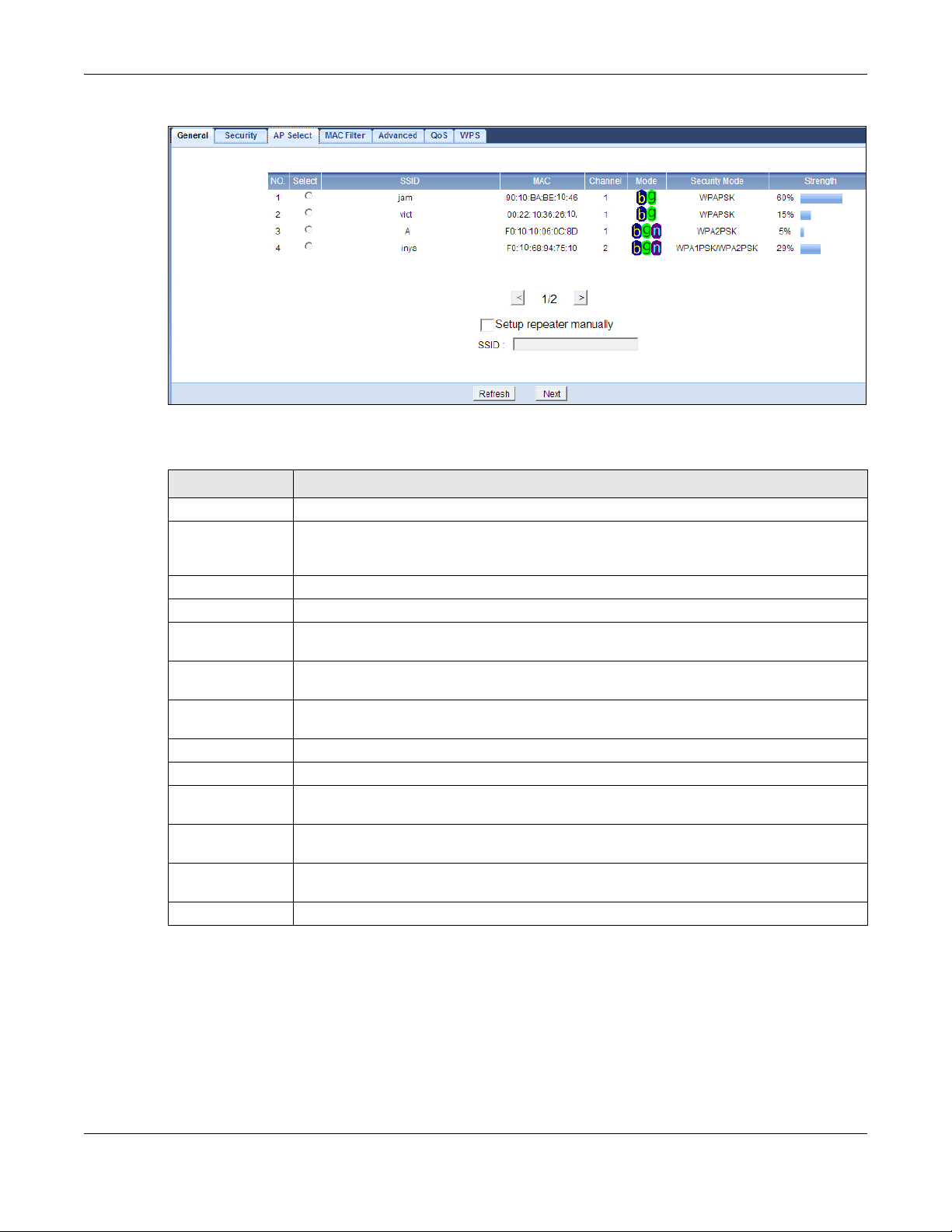
Chapter 9 Wireless LAN
Figure 42 Network > Wireless LAN (2.4G/5G) > AP Select (Repeater Mode)
The following table describes the labels in this screen.
Table 19 Network > Wireless LAN (2.4G/5G) > AP Select (Repeater Mode)
LABEL DESCRIPTION
Select Use the radio button to select the wireless device to which you want to connect.
SSID This displays the Service Set IDentity of the wireless device. The SSID is a unique name
MAC This displays the MAC address of the wireless device.
Channel This displays the channel number used by this wireless device.
Mode This displays which IEEE 802.11b/g/n wireless networking standards the wireless device
Security Mode This displays the type of security configured on the wireless device. When no is shown, no
Strength This displays the strength of the wireless signal. The signal strength mainly depends on
< Click < to see the previous page of APs.
> Click > to see the next page of APs.
Setup repeater
manually
SSID If Setup repeater manually is selected, use this field to type the SSID of the AP. This is
Refresh Click Refresh to search for available wireless devices within transmission range and
Next Click Next to start the next step in the AP setup process.
that identifies a wireless network. All devices in a wireless network must use the same
SSID.
supports.
security is configured and you can connect to it without a password.
the antenna output power and the distance between your WRE6505 and this device.
Select this to setup the AP manually.
useful when the AP’s SSID is hidden.
update this table.
9.7 MAC Filter
The MAC Filter screen allows you to specify which devices are allowed to access the WRE6505,
while denying access to all unspecified devices. Every Ethernet device has a unique MAC (Media
Access Control) address. The MAC address is assigned at the factory and consists of six pairs of
WRE6505 User’s Guide
57
Page 58

Chapter 9 Wireless LAN
hexadecimal characters, for example, 00:A0:C5:00:00:02. You need to know the MAC address of
the devices to configure this screen.
To change your WRE6505’s MAC Address List settings, click Network > Wireless LAN (2.4G/5G)
> MAC Filter. The screen appears as shown.
Figure 43 Network > Wireless LAN (2.4G/5G) > MAC Filter
The following table describes the labels in this menu.
Table 20 Network > Wireless LAN (2.4G/5G)> MAC Address List
LABEL DESCRIPTION
Active Select this to enable MAC address filtering.
SSID for MAC
Filter
MAC Address
Filter
Filter Action Select Disable to deactivate the MAC filtering rule.
Set This is the index number of the MAC address.
MAC Address Enter the MAC addresses of the wireless station to include in the rule. Enter the MAC
Apply Click Apply to save your changes back to the WRE6505.
Cancel Click Cancel to return to the previous menu without saving.
Select the SSID for which you want to configure MAC filtering.
Select Enable to allow MAC address filtering (default: Disable).
Select Allow to permit access to the WRE6505, MAC addresses not listed will be denied
access to the WRE6505.
addresses in a valid MAC address format, that is, six hexadecimal character pairs, for
example, 12:34:56:78:9a:bc.
WRE6505 User’s Guide
58
Page 59

Chapter 9 Wireless LAN
9.8 Wireless LAN Advanced Screen
Use this screen to configure advanced wireless LAN parameters.
Click Network > Wireless LAN (2.4G/5G) > Advanced. The screen appears as shown.
Figure 44 Network > Wireless LAN (2.4G/5G) > Advanced
The following table describes the labels in this screen.
Table 21 Network > Wireless LAN (2.4G/5G) > Advanced
LABEL DESCRIPTION
RTS/CTS
Threshold
Data with its frame size larger than this value will perform the RTS (Request To Send)/
CTS (Clear To Send) handshake.
Fragmentation
Threshold
Preamble Type A preamble affects the timing in your wireless network. There are two preamble modes:
Apply Click Apply to save your changes to the WRE6505.
Cancel Click Cancel to return to the previous menu without saving.
9.9 WPS Screen
Use this screen to enable/disable WPS, view or generate a new PIN and check current WPS status.
To open this screen, click Network > Wireless LAN (2.4G/5G) > WPS tab.
Enter a value between 0 and 2347.
The threshold (number of bytes) for the fragmentation boundary for directed messages.
It is the maximum data fragment size that can be sent. Enter an even number between
256 and 2346.
long and short. If a device uses a different preamble mode than the WRE6505 does, it
cannot communicate with the WRE6505.
WRE6505 User’s Guide
59
Page 60

Chapter 9 Wireless LAN
Figure 45 Network > Wireless LAN (2.4G/5G) > WPS
The following table describes the labels in this screen.
Table 22 Network > Wireless LAN (2.4G/5G) > WPS
LABEL DESCRIPTION
WPS Setup
WPS Select this to enable the WPS feature.
PIN Number This displays a PIN number last time system generated. Click Generate to generate a
WPS Status
Status This displays Configured when the WRE6505 has connected to a wireless network using
new PIN number.
WPS or when Enable WPS is selected and wireless or wireless security settings have
been changed. The current wireless and wireless security settings also appear in the
screen.
This displays Unconfigured if WPS is disabled and there are no wireless or wireless
security changes on the WRE6505 or click Release Configuration (AP mode only) to
remove the configured wireless and wireless security settings.
Release
Configuration
(AP mode only)
802.11 Mode This is the 802.11 mode used. Only compliant WLAN devices can associate with the
SSID This is the name of the wireless network (the WAP3205 v2’s first SSID).
Security This is the type of wireless security employed by the network.
Apply Click Apply to save your changes back to the WRE6505.
Cancel Click Cancel to return to the previous menu without saving.
This button is only available when the WPS status displays Configured.
Click this button to remove all configured wireless and wireless security settings for WPS
connections on the WRE6505.
WRE6505.
9.10 WPS Station Screen
Use this screen (available in AP mode only) when you want to add a wireless station using WPS. To
open this screen, click Network > Wireless LAN (2.4/5G) > WPS Station tab.
WRE6505 User’s Guide
60
Page 61

Chapter 9 Wireless LAN
Note: After you click Push Button on this screen, you have to press a similar button in
the wireless station utility within 2 minutes. To add the second wireless station, you
have to press these buttons on both device and the wireless station again after the
first 2 minutes.
Figure 46 Network > Wireless LAN (2.4/5G) > WPS Station
The following table describes the labels in this screen.
Table 23 Network > Wireless LAN (2.4/5G)> WPS Station
LABEL DESCRIPTION
Push Button Use this button when you use the PBC (Push Button Configuration) method to configure
wireless stations’s wireless settings. See Section 8.3.1 on page 60.
Click this to start WPS-aware wireless station scanning and the wireless security
information synchronization.
Or input station’s
PIN number
Use this button when you use the PIN Configuration method to configure wireless station’s
wireless settings. See Section 8.3.2 on page 61.
Type the same PIN number generated in the wireless station’s utility. Then click Start to
associate to each other and perform the wireless security information synchronization.
9.11 Scheduling Screen
Use this screen (available in AP mode only) to set the times your wireless LAN is turned on and off.
Wireless LAN scheduling is disabled by default. The wireless LAN can be scheduled to turn on or off
on certain days and at certain times. To open this screen, click Network > Wireless LAN (2.4/
5G) > Scheduling tab.
WRE6505 User’s Guide
61
Page 62

Chapter 9 Wireless LAN
Figure 47 Network > Wireless LAN (2.4/5G) > Scheduling
The following table describes the labels in this screen.
Table 24 Network > Wireless LAN (2.4/5G) > Scheduling
LABEL DESCRIPTION
Wireless LAN Scheduling
Enable Wireless
LAN Scheduling
Scheduling
WLAN Status Select On or Off to specify whether the Wireless LAN is turned on or off. This field works
Day Select Everyday or the specific days to turn the Wireless LAN on or off. If you select
For the following
times (24-Hour
Format)
Apply Click Apply to save your changes back to the WRE6505.
Cancel Click Cancel to reload the previous configuration for this screen.
Select this to enable Wireless LAN scheduling.
in conjunction with the Day and For the following times fields.
Everyday you can not select any specific days. This field works in conjunction with the
For the following times field.
Select a begin time using the first set of hour and minute (min) drop down boxes and
select an end time using the second set of hour and minute (min) drop down boxes. If
you have chosen On earlier for the WLAN Status the Wireless LAN will turn on between
the two times you enter in these fields. If you have chosen Off earlier for the WLAN
Status the Wireless LAN will turn off between the two times you enter in these fields.
WRE6505 User’s Guide
62
Page 63

CHAPTER 10
10.1 Overview
This screen allows you to assign the WRE6505 a fixed or dynamic IP address. The default IP
address is 192.168.1.2. In initial configuration, the WRE6505 acts as a DHCP server, so it can
assign your computer an IP address in the same network range as the default IP. After the
WRE6505 connects to an AP, the DHCP server function is disabled and your computer gets its IP
from the AP. If the AP connection is dropped, connect to the WRE6505 again using the default
domain name, http://zyxelsetup. The MAC address can be found on a label on the product.
10.2 What You Need To Know
The LAN parameters of the WRE6505 are preset in the factory with the following values:
LAN
• IP address of 192.168.1.2 with subnet mask of 255.255.255.0 (24 bits)
10.3 LAN IP Screen
Use this screen to change your basic LAN settings. Click Network > LAN.
Figure 48 Network > LAN > IP
WRE6505 User’s Guide
63
Page 64

Chapter 10 LAN
The following table describes the labels in this screen.
Table 25 Network > LAN > IP
LABEL DESCRIPTION
Get from DHCP
Server
User Defined LAN IPClick this to enable the manual IP configuration.
IP Address Enter the IP address of your WRE6505 in dotted decimal notation 192.168.1.2 (factory
IP Subnet Mask Enter the subnet mask of your WRE6505 in dotted decimal notation.
IP Gateway Enter the gateway of your WRE6505 in dotted decimal notation.
Apply Click Apply to save your changes back to the WRE6505.
Cancel Click Cancel to reload the previous configuration for this screen.
Select this to have the WRE6505 get a dynamic IP address from a DHCP server.
default).
WRE6505 User’s Guide
64
Page 65

11.1 Overview
This chapter provides information on the System screen.
11.2 What You Can Do
Use the Password screen to set the password (Section 11.4 on page 66).
Use the Firmware Upgrade screen to update firmware (Section 11.5 on page 66).
Use the Backup/Restore screen to backup and restore device configurations (Section 11.6 on
page 68).
CHAPTER 11
System
Use the Language screen to select the interface display language (Section 11.7 on page 70).
Use the System Mode screen to select the WPS behavior (Section 11.8 on page 70).
11.3 General
Use this screen to set the system and domain names. Click Maintenance > General. The following
screen displays.
Figure 49 Maintenance > General
WRE6505 User’s Guide
65
Page 66
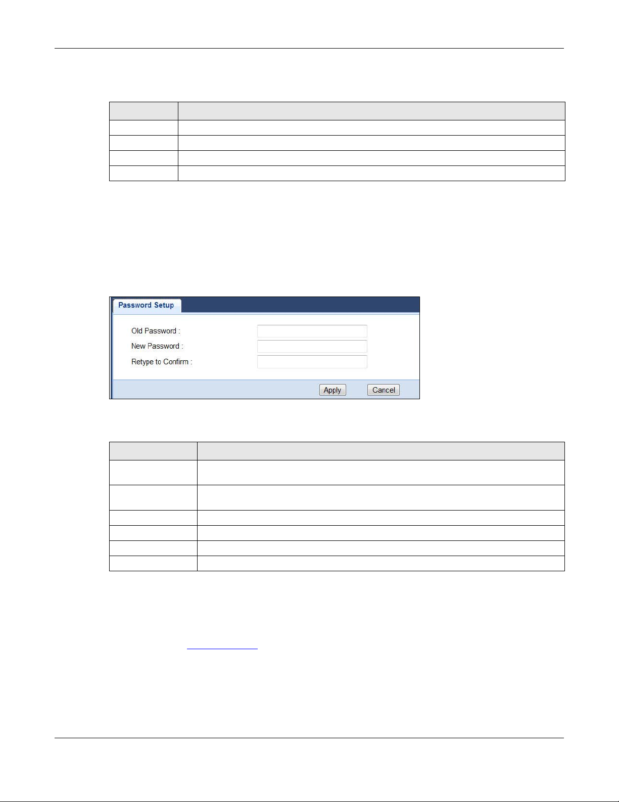
Chapter 11 System
The following table describes the labels in this menu.
Table 26 Maintenance > General
LABEL DESCRIPTION
System Name Type the name used to designate the system.
Domain Name Type the domain name used to designate the system.
Apply
Cancel
11.4 System Password Screen
Use this screen to set the web configurator password. Click Maintenance > System. The following
screen displays.
Figure 50 Maintenance > Password
The following table describes the labels in this screen.
Table 27 Maintenance > System > Password
LABEL DESCRIPTION
Old Password Type the default password or the existing password you use to access the system in this
field.
New Password Type your new system password (up to 30 characters). Note that as you type a
password, the screen displays an asterisk (*) for each character you type.
Retype to Confirm Type the new password again in this field.
Apply Click Apply to save your changes back to the WRE6505.
Reset Click Reset to begin configuring this screen afresh.
Cancel
11 .5 Firmware Upgrade Screen
Find firmware at www.zyxel.com in a file that (usually) uses the system model name with a “*.bin”
extension, e.g., “WRE6505.bin”. The upload process uses HTTP (Hypertext Transfer Protocol) and
may take up to two minutes. After a successful upload, the system will reboot.
Click Maintenance > Firmware Upgrade. Follow the instructions in this screen to upload
firmware to your WRE6505.
WRE6505 User’s Guide
66
Page 67
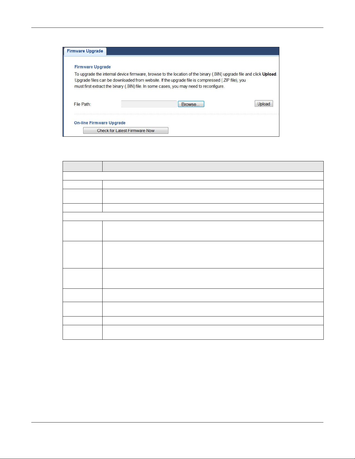
Chapter 11 System
Figure 51 Maintenance > Firmware Upgrade
The following table describes the labels in this screen.
Table 28 Maintenance > Firmware Upgrade
LABEL DESCRIPTION
Firmware Upgrade
File Path Type in the location of the file you want to upload in this field or click Browse... to find it.
Browse... Click Browse... to find the .bin file you want to upload. Remember that you must
decompress compressed (.zip) files before you can upload them.
Upload Click Upload to begin the upload process. This process may take up to two minutes.
On-line Firmware Upgrade
Check for
Latest
Firmware Now
You are
currently
using
firmware
version:
The Latest
Firmware
Version
Release
Date
Release
Note
Size This is the size of the firmware in bytes. 15073234 is about 15 MB.
Do_Firmware_
Upgrade
The following fields display when you click this button.
The firmware version consists of the trunk version number, model code, and release number.
For example, V1.00(AAAG.5) means V1.00 is the trunk number, AAAG represents WRE6505,
and 5 means the fifth release.
Compare the release number in the previous field with the release number in this one to see
if you have the latest firmware. In this example, V1.00(AAAG.5), the numbers are the same
(5), so the WRE6505 already has the latest firmware.
The date the firmware was issued is shown in year-month-date format.
The release note shows what has changed (new features, bug fixes, known issues) in this
firmware version. Check the Release Note before deciding to use new firmware.
Click this button to download and upgrade the new firmware to the WRE6505.
Note: Do not turn off the WRE6505 while firmware upload is in progress!
After you see the Firmware Upgrading screen, wait until the upgrade process is complete.
WRE6505 User’s Guide
67
Page 68
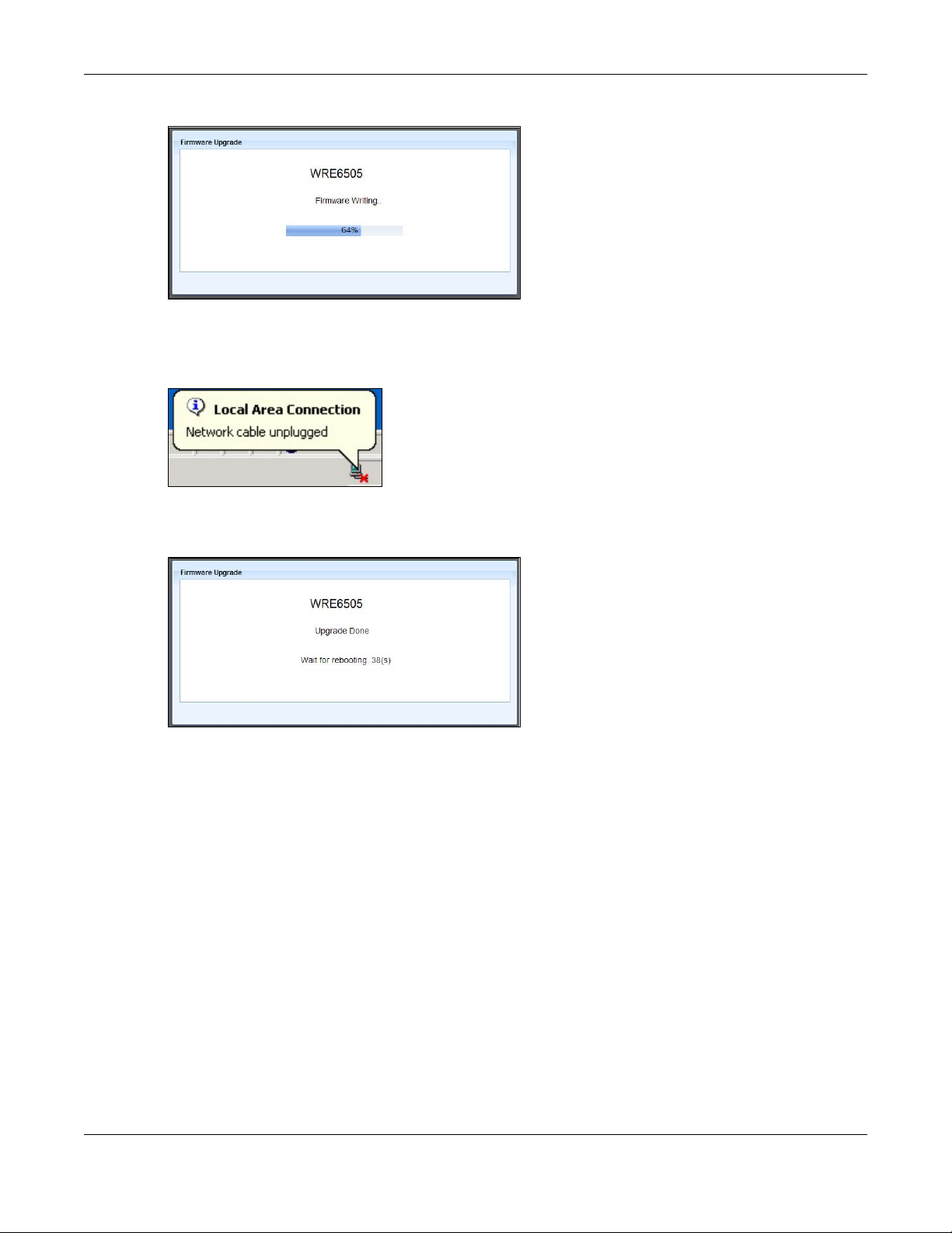
Chapter 11 System
Figure 52 Firmware Upgrading
The WRE6505 automatically restarts in this time causing a temporary network disconnect. In some
operating systems, you may see the following icon on your desktop.
Figure 53 Network Temporarily Disconnected
After the WRE6505 restarts, the Upgrade Accomplished screen appears.
Figure 54 Upgrade Accomplished
Refresh the web page and log in again and check your new firmware version in the Status screen.
11.6 Backup / Restore Screen
Click Maintenance > Backup/Restore. Information related to factory defaults, backup
configuration, and restoring configuration appears as shown next.
WRE6505 User’s Guide
68
Page 69
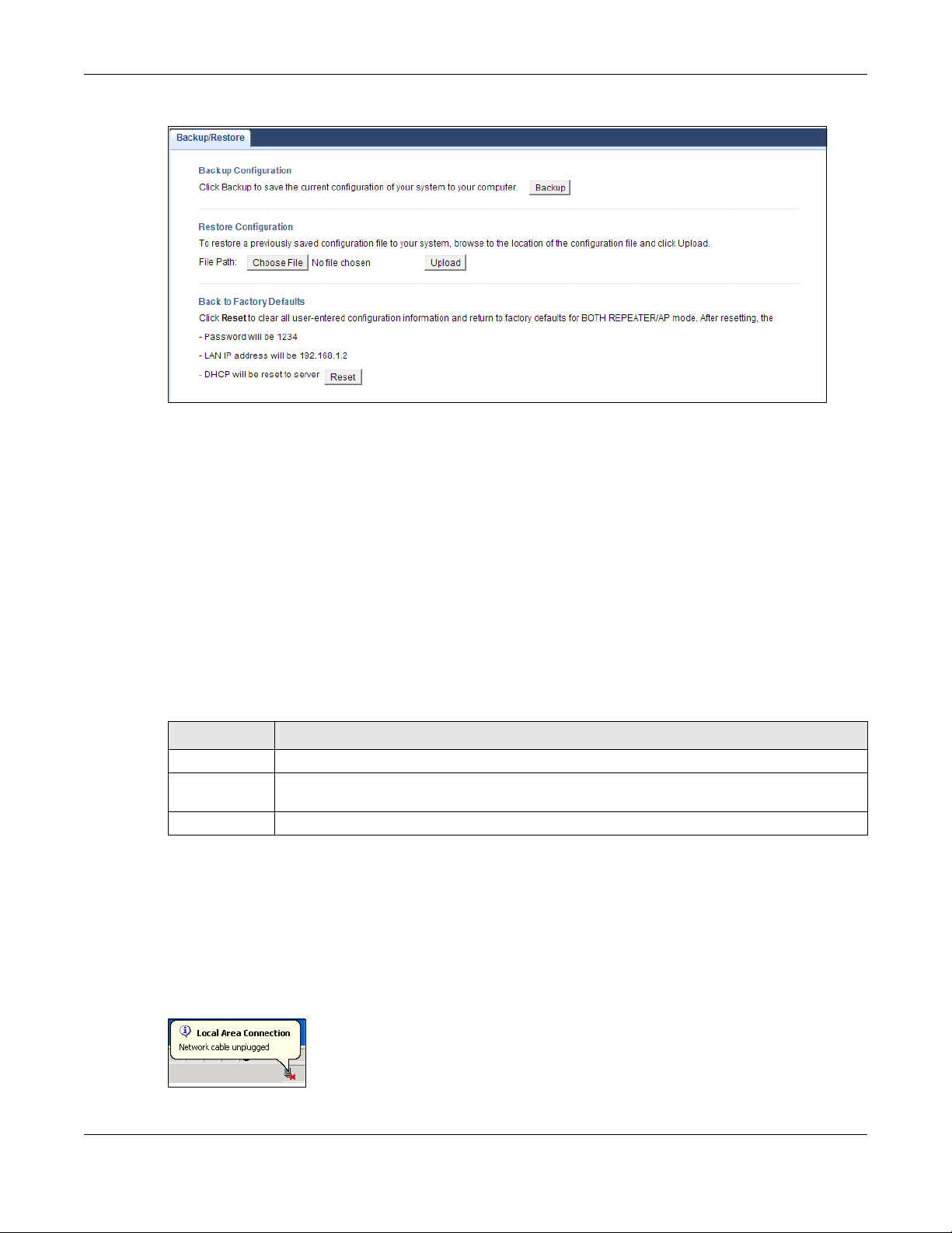
Figure 55 Maintenance > Backup/Restore
11.6.1 Backup Configuration
Backup configuration allows you to back up (save) the WRE6505’s current configuration to a file on
your computer. Once your WRE6505 is configured and functioning properly, it is highly
recommended that you back up your configuration file before making configuration changes. The
backup configuration file will be useful in case you need to return to your previous settings.
Chapter 11 System
Click Backup to save the WRE6505’s current configuration to your computer.
11.6.2 Restore Configuration
Restore configuration allows you to upload a new or previously saved configuration file from your
computer to your WRE6505.
Table 29 Maintenance Restore Configuration
LABEL DESCRIPTION
File Path Type in the location of the file you want to upload in this field or click Browse... to find it.
Browse... Click Browse... to find the file you want to upload. Remember that you must decompress
Upload Click Upload to begin the upload process.
Note: Do not turn off the WRE6505 while configuration file upload is in progress.
After you see a “configuration upload successful” screen, you must then wait one minute before
logging into the WRE6505 again.
The WRE6505 automatically restarts in this time causing a temporary network disconnect. In some
operating systems, you may see the following icon on your desktop.
Figure 56 Temporarily Disconnected
compressed (.ZIP) files before you can upload them.
WRE6505 User’s Guide
69
Page 70
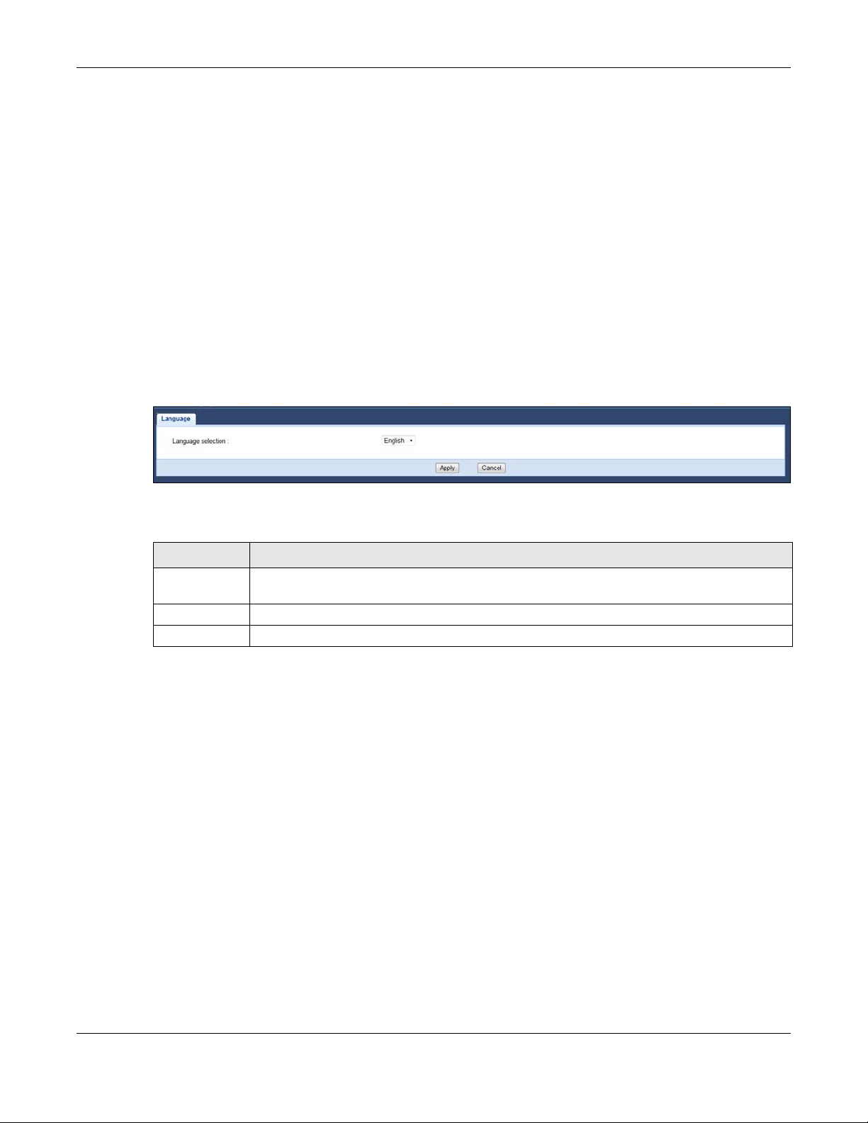
Chapter 11 System
If you uploaded the default configuration file you may need to change the IP address of your
computer to be in the same subnet as that of the default WRE6505 IP address (192.168.1.2). Refer
to your operating system’s help files for details on how to set up your computer’s IP address.
11.6.3 Restore to Factory Defaults
Pressing the WPS button (see Section 1.4 on page 12) on the front panel for more than 10 seconds
resets the factory defaults of your WRE6505. Refer to Section 1.4 on page 12 for more information
on the resetting the WRE6505.
11.7 Language
Click Maintenance > Language to select the language for use in the user interface.
Figure 57 Maintenance > Language
The following table describes the labels in this menu.
Table 30 Maintenance > Language
LABEL DESCRIPTION
Language
selection
Apply Click Apply to save your changes back to the WRE6505.
Cancel Click Cancel to reload the previous configuration for this screen.
Click the drop-down menu to select the display language.
11.8 System Mode
For further information on System Mode see Section 2.1.1 on page 13.
WRE6505 User’s Guide
70
Page 71
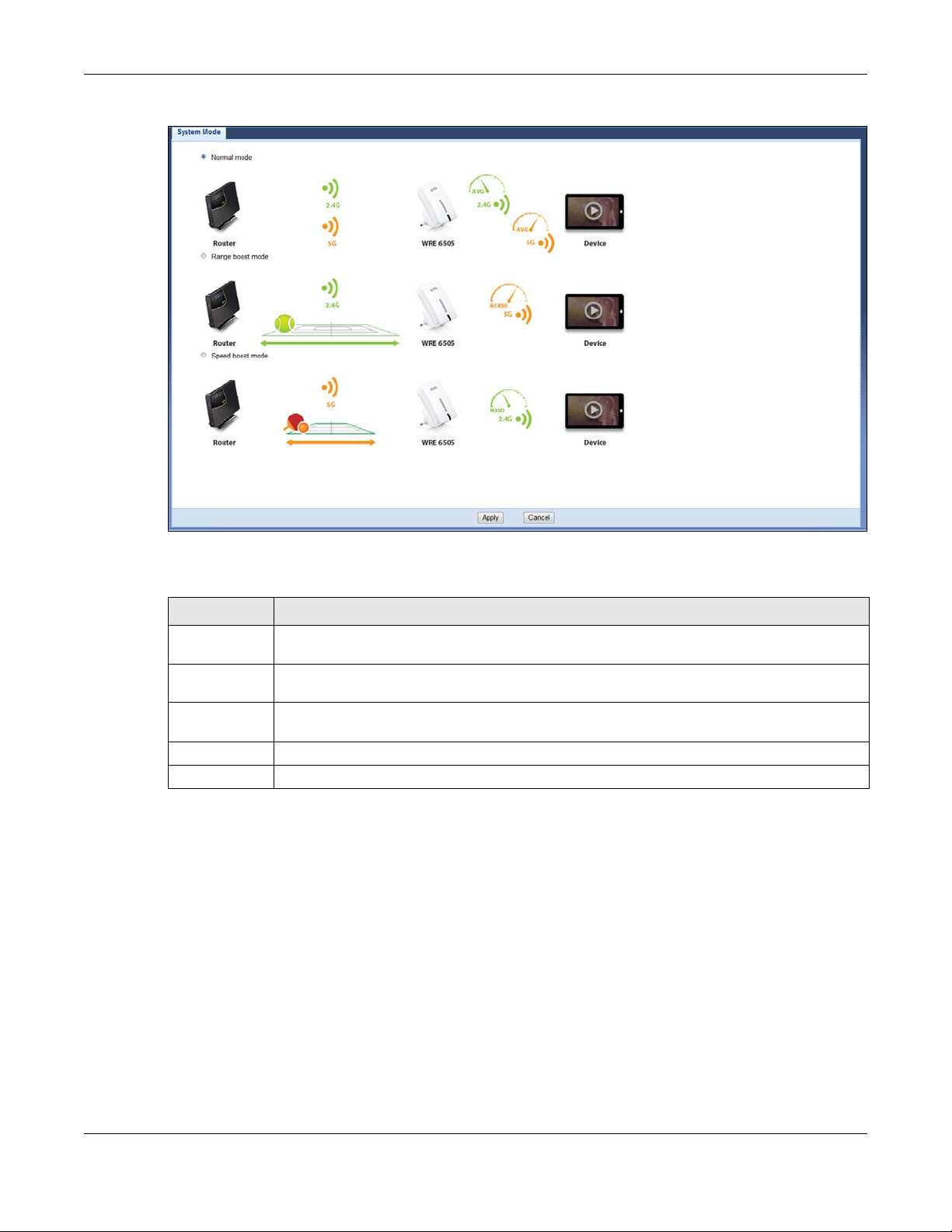
Chapter 11 System
Figure 58 Maintenance > System Mode
The following table describes the labels in this menu.
Table 31 Maintenance > System Mode
LABEL DESCRIPTION
Normal mode The default WPS behavior, both 2.4 GHz and 5 GHz bands are supported in up and down
Range boost
mode
Speed boost
mode
Apply Click Apply to save your changes back to the WRE6505.
Cancel Click Cancel to reload the previous configuration for this screen.
broadcasting.
Select to set the device to Range Boost mode--the 2.4 GHz band is supported on the Down
behavior, while the 5 GHz band is supported on the Up behavior.
Select to set the device to Range Boost mode--the 5 GHz band is supported on the Down
behavior, while the 2.4 GHz band is supported on the Up behavior.
11.8.1 System WPS Behavior
In Universal Repeater mode (see Chapter 2 on page 14), you can select the type of WPS behavior:
Normal Mode, Range Boost, or Speed Boost mode.
The device enables you to extend the range of your dual-band router to eliminate "dead spots" in
your wireless network. You can choose from normal mode, range boost, or speed boost modes for
both your 2.4GHz and 5GHz networks.
The following terms are used to describe the WPS behavior:
• Up: The connection from the WRE6505 to the Router
• Down: The connection from the WRE6505 to a client
WRE6505 User’s Guide
71
Page 72
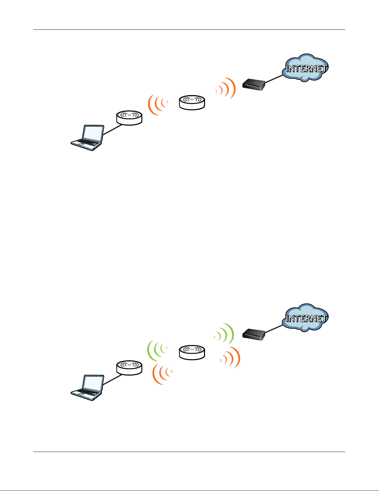
Chapter 11 System
Universal
Repeater
Client
Up
Router
Down
Universal
Repeater
Client
2. 4 GHz / 5 GH z
Up
2.4 GHz / 5 GHz
Down
Figure 59 Normal Mode with Up and Down Broadcasting
• Home wireless network: 2.4G SSID = Home2.4G_2.4GEXT; 5G SSID = Home5G_5GEXT.
• Work wireless network: 2.4G SSID = Work2.4G_2.4GEXT; 5G SSID = Work5G_5GEXT.
• No profile: There is no currently defined profile.
The following section describes the Normal, Range Boost, and Speed Boost mode (WPS) behaviors
in a home and work network connection.
As connection profiles are established, the WRE6505 maintains a record of the varying profiles and
automatically joins the network when in range.
Note: The home wireless network is the initial setup environment. The WRE6505 does not
have any established network profiles at the time of initial setup.
11.8.1.1 Normal Mode
In normal mode, both Down and Up WPS behaviors are supported for both 2.4 GHz and 5 GHz
bands.
Figure 60 Maintenance > System Mode> Normal mode
WRE6505 User’s Guide
72
Page 73

Chapter 11 System
Universal
Repeater
Client
2.4 GHz
Up
5 GH z
Down
The following table describes the labels in the previous screen.
Table 32 WPS Behavior: Normal Mode
HOME WIRELESS NETWORK WORK WIRELESS NETWORK
WPS BAND UP DOWN UP DOWN
2.4 GHz No profile
(Initial Setup)
No profile No profile No profile Work2_2.4GEXT
Home1 Home1_2.4GEXT Work3 Work3_2.4GEXT
no profile no profile No profile Work4_2.4GEXT
Home1 Home1_2.4GEXT Work3 Work3_2.4GEXT
Home1 Home1_2.4GEXT Work1 Work1_2.4GEXT
5 GHz No profile
(Initial Setup)
No profile No profile Work2_5GEXT Work2_5GEXT
No profile No profile No profile Work3_5GEXT
Home2 Home2_5GEXT Work4 Work4_5GEXT
Home2 Home2_5GEXT Work2_5GEXT Work2_5GEXT
Home2 Home2_5GEXT Work4 Work4_5GEXT
No profile
(Initial Setup)
No profile
(Initial Setup)
Work1 Work1_2.4GEXT
No profile Work1_5GEXT
11.8.1.2 Range Boost Mode
In range boost mode, the 2.4 GHz band is supported on the Down behavior, while the 5 GHz band is
supported on the Up behavior.
Figure 61 WPS Behavior: Range Boost Mode
WRE6505 User’s Guide
73
Page 74

The following table describes the labels in the previous screen.
Universal
Repeater
Client
5 GH z
Up
2.4 GHz
Down
Table 33 WPS Behavior: Range Boost Mode
WPS BAND UP DOWN UP DOWN
2.4 GHz No profile
5 GHz No profile
1 1 .8.1.3 Speed Boost Mode
In speed boost mode, the 5 GHz band is supported on the Down behavior, while the 2.4 GHz band
is supported on the Up behavior.
Chapter 11 System
HOME WIRELESS NETWORK WORK WIRELESS NETWORK
(Initial Setup)
Home1 Home1_2.4GEXT Work3 Off
No profile Home2_2.4GEXT Work3 Off
Home1 Home1_2.4GEXT Work3 Off
(Initial Setup)
Home2 Home2_5GEXT Work2 Work3_5GEXT
Home2 Home2_5GEXT Work2 Work3_5GEXT
No profile No profile No profile Work3_5GEXT
No profile
(Initial Setup)
No profile
(Initial Setup)
Work1 Off
No profile Work1_5GEXT
Figure 62 WPS Mode: Speed Boost Mode
The following table describes the labels in the previous screen.
Table 34 WPS Mode: Speed Boost Mode
HOT SPOT 1 (HOME) HOT SPOT 2 (WORK)
WPS BAND UP DOWN UP DOWN
2.4 GHz No profile
(Initial Setup)
Home1 Home1_2.4GEXT Work1 Work4_2.4GEXT
No profile Home2_2.4GEXT No profile Work4_2.4GEXT
Home1 Home1_2.4GEXT Work1 Work3_2.4GEXT
No profile
(Initial Setup)
No profile Work2_2.4GEXT
WRE6505 User’s Guide
74
Page 75

Chapter 11 System
Table 34 WPS Mode: Speed Boost Mode (continued)
HOT SPOT 1 (HOME) HOT SPOT 2 (WORK)
WPS BAND UP DOWN UP DOWN
5 GHz No profile
(Initial Setup)
Home2 Home2_5GEXT Work4 Off
Home2 Home2_5GEXT Work4 Off
No profile No profile Work3 Off
No profile
(Initial Setup)
Work2 Off
WRE6505 User’s Guide
75
Page 76

CHAPTER 12
Troubleshooting
This chapter offers some suggestions to solve problems you might encounter. The potential
problems are divided into the following categories.
• Power, Hardware Connections, and LEDs
• WRE6505 Access and Login
• Internet Access
• Resetting the WRE6505 to Its Factory Defaults
• Wireless Problems
12.1 Power, Hardware Connections, and LEDs
The WRE6505 does not turn on. None of the LEDs turn on.
1 Make sure the WRE6505 is plugged in to an appropriate power source. Make sure the power source
is turned on.
2 Disconnect and re-connect the power adaptor or cord to the WRE6505.
3 If the problem continues, contact the vendor.
One of the LEDs does not behave as expected.
1 Make sure you understand the normal behavior of the LED. See Section 1.3 on page 10.
2 Make sure you understand how the LEDs are enabled or disabled. See Section 1.3 on page 10.
3 Check the hardware connections. See the Quick Start Guide.
4 Inspect your cables for damage. Contact the vendor to replace any damaged cables.
5 Disconnect and re-connect the power adaptor to the WRE6505.
6 If the problem continues, contact the vendor.
WRE6505 User’s Guide
76
Page 77

Chapter 12 Troubleshooting
12.2 WRE6505 Access and Login
I don’t know the IP address of my WRE6505.
1 Click Start > Run, enter cmd, and then enter Ping zyxelsetup.
2 The default IP address is 192.168.1.2.
Note: In Repeater mode, you can access the login screen by using the IP address
(192.168.1.2) or by typing “http://zyxelsetup” in your browser IP address bar.
While in AP mode, connect the WRE6505 to your router (configured under same
subnet) and type “http://zyxelsetup” in your browser IP address bar.
3 If you changed the IP address and have forgotten it, you might get the IP address of the WRE6505
by looking up the IP address of the default gateway for your computer. To do this in most Windows
computers, click Start > Run, enter cmd, and then enter ipconfig. The IP address of the Default
Gateway might be the IP address of the WRE6505 (it depends on the network), so enter this IP
address in your Internet browser. Login (see the Quick Start Guide for instructions) and go to the
Device Information table in the Status screen. Your WRE6505’s IP address is available in the
Device Information table.
•If the DHCP setting under LAN information is None, your device has a fixed IP address.
•If the DHCP setting under LAN information is Client, then your device receives an IP
address from a DHCP server on the network.
4 If your WRE6505 is a DHCP client, you can find your IP address from the DHCP server. This
information is only available from the DHCP server which allocates IP addresses on your network.
Find this information directly from the DHCP server or contact your system administrator for more
information.
5 Reset your WRE6505 to change all settings back to their default. This means your current settings
are lost. See Section 12.4 on page 80 in the Troubleshooting for information on resetting your
WRE6505.
I forgot the username and password.
1 The default username is admin and default password is 1234.
2 If this does not work, you have to reset the device to its factory defaults. See Section 11.6.3 on
page 70.
I cannot see or access the Login screen in the Web Configurator.
1 Make sure you are using the correct IP address.
WRE6505 User’s Guide
77
Page 78

Chapter 12 Troubleshooting
• The default IP address is 192.168.1.2.
• If you changed the IP address, use the new IP address.
• If you changed the IP address and have forgotten it, see the troubleshooting suggestions for I
don’t know the IP address of my WRE6505.
2 Check the hardware connections, and make sure the LEDs are behaving as expected. See the Quick
Start Guide.
3 Make sure your Internet browser does not block pop-up windows and has JavaScript and Java
enabled.
4 Make sure your computer is in the same subnet as the WRE6505. (If you know that there are
routers between your computer and the WRE6505, skip this step.)
• If there is a DHCP server on your network, make sure your computer is using a dynamic IP
address.
• If there is no DHCP server on your network, make sure your computer’s IP address is in the
same subnet as the WRE6505.
5 Reset the device to its factory defaults, and try to access the WRE6505 with the default IP address.
6 If the problem continues, contact the network administrator or vendor, or try one of the advanced
suggestions.
Advanced Suggestions
• If your computer is connected wirelessly, use a computer that is connected to a LAN/ETHERNET
port.
I can see the Login screen, but I cannot log in to the WRE6505.
1 Make sure you have entered the password correctly. The default username is admin and default
password is 1234. This field is case-sensitive, so make sure [Caps Lock] is not on.
2 This can happen when you fail to log out properly from your last session. Try logging in again after
5 minutes.
3 Disconnect and re-connect the power adaptor or cord to the WRE6505.
4 If this does not work, you have to reset the device to its factory defaults. See Section 12.4 on page
80.
12.3 Internet Access
I cannot access the Internet.
WRE6505 User’s Guide
78
Page 79

Chapter 12 Troubleshooting
1 Check the hardware connections, and make sure the LEDs are behaving as expected. See the Quick
Start Guide.
2 Try to connect directly to the AP. If you can access the Internet, check that the WRE6505 has
associated with the AP by checking the WLAN STA Information SSID field shows the SSID of the
AP. See Section 9.4 on page 55.
3 If you are trying to access the Internet wirelessly, make sure the wireless settings in the wireless
client are the same as the settings in the AP.
4 Disconnect all the cables from your device, and follow the directions in the Quick Start Guide again.
5 If the problem continues, contact your ISP.
I cannot access the Internet anymore. I had access to the Internet (with the WRE6505), but
my Internet connection is not available anymore.
1 Check the hardware connections, and make sure the LEDs are behaving as expected. See the Quick
Start Guide and Section 1.3 on page 10.
2 Reboot the WRE6505.
3 Try to connect directly to the AP. If you can access the Internet, check that the WRE6505 has
associated with the AP by checking the WLAN STA Information SSID field shows the SSID of the
AP. See Section 9.4 on page 55.
4 If the problem continues, contact your ISP.
The Internet connection is slow or intermittent.
1 There might be a lot of traffic on the network. Look at the LEDs, and check Section 1.3 on page 10.
If the WRE6505 is sending or receiving a lot of information, try closing some programs that use the
Internet, especially peer-to-peer applications.
2 Check the signal strength. If the signal strength is low, try moving the WRE6505 closer to the AP if
possible, and look around to see if there are any devices that might be interfering with the wireless
network (for example, microwaves, other wireless networks, and so on).
3 Reboot the WRE6505.
4 If the problem continues, contact the network administrator or vendor, or try one of the advanced
suggestions.
Advanced Suggestion
• Check the settings for QoS. If it is disabled, you might consider activating it.
WRE6505 User’s Guide
79
Page 80

Chapter 12 Troubleshooting
12.4 Resetting the WRE6505 to Its Factory Defaults
If you reset the WRE6505, you lose all of the changes you have made. The WRE6505 re-loads its
default settings, and the username/password resets to admin/1234. You have to make all of your
changes again.
You will lose all of your changes when you reset the WRE6505 to its factory defaults.
To reset the WRE6505,
1 Make sure the power LED is on.
2 Press the WPS button for longer than 10 seconds, the Power LED begins to blink, to set the
WRE6505 back to its factory-default configuration.
OR
3 Click Maintenance > Backup/Restore > Restore and then click Reset.
If the WRE6505 restarts automatically, wait for the WRE6505 to finish restarting, and log in to the
Web Configurator. The username is admin and password is 1234.
If the WRE6505 does not restart automatically, disconnect and reconnect the WRE6505’s power.
Then, follow the directions above again.
12.5 Wireless Problems
I cannot access the WRE6505 or ping any computer from the WLAN.
1 Make sure the wireless LAN is enabled on the WRE6505.
2 Make sure the wireless adapter on the wireless station is working properly.
3 Make sure the wireless adapter installed on your computer is IEEE 802.11 compatible and supports
the same wireless standard as the WRE6505.
4 Make sure your computer (with a wireless adapter installed) is within the transmission range of the
WRE6505.
5 Check that both the WRE6505 and your wireless station are using the same wireless and wireless
security settings, and that both the WRE6505 and the AP are using the same wireless and wireless
security settings.
6 Make sure traffic between the WLAN and the LAN is not blocked by the MAC Address List of the
WRE6505. See Section 9.7 on page 57.
WRE6505 User’s Guide
80
Page 81

APPENDIX A
Setting Up Your Computer’s IP Address
Note: Your specific WRE6505 may not support all of the operating systems described in
this appendix. See the product specifications for more information about which
operating systems are supported.
This appendix shows you how to configure the IP settings on your computer in order for it to be
able to communicate with the other devices on your network. Windows Vista/XP/2000, Mac OS 9/
OS X, and all versions of UNIX/LINUX include the software components you need to use TCP/IP on
your computer.
If you manually assign IP information instead of using a dynamic IP, make sure that your network’s
computers have IP addresses that place them in the same subnet.
In this appendix, you can set up an IP address for:
• Windows XP/NT/2000 on page 81
• Windows Vista on page 85
• Windows 7 on page 89
• Mac OS X: 10.3 and 10.4 on page 93
• Mac OS X: 10.5 and 10.6 on page 96
• Linux: Ubuntu 8 (GNOME) on page 99
• Linux: openSUSE 10.3 (KDE) on page 103
Windows XP/NT/2000
The following example uses the default Windows XP display theme but can also apply to Windows
2000 and Windows NT.
1 Click Start > Control Panel.
WRE6505 User’s Guide
81
Page 82
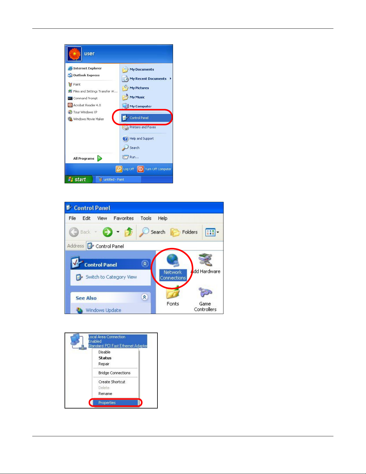
Appendix A Setting Up Your Computer’s IP Address
2 In the Control Panel, click the Network Connections icon.
3 Right-click Local Area Connection and then select Properties.
4 On the General tab, select Internet Protocol (TCP/IP) and then click Properties.
WRE6505 User’s Guide
82
Page 83
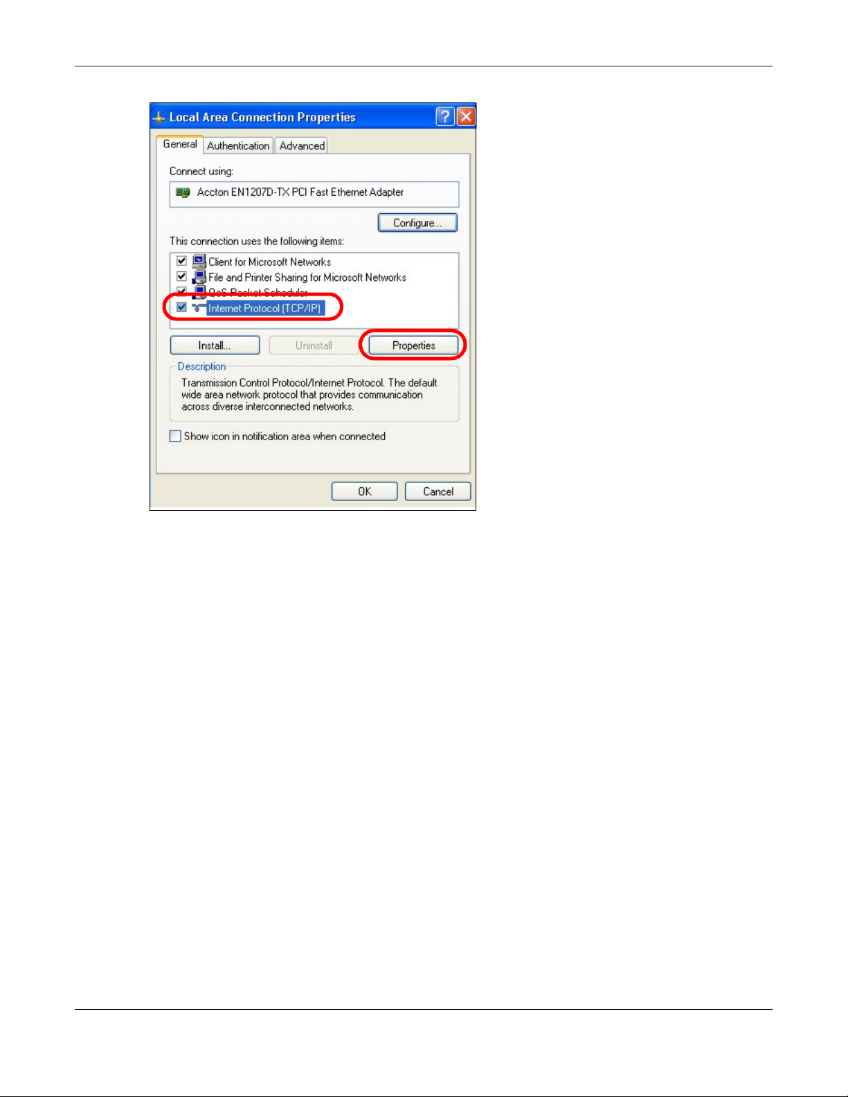
Appendix A Setting Up Your Computer’s IP Address
5 The Internet Protocol TCP/IP Properties window opens.
WRE6505 User’s Guide
83
Page 84
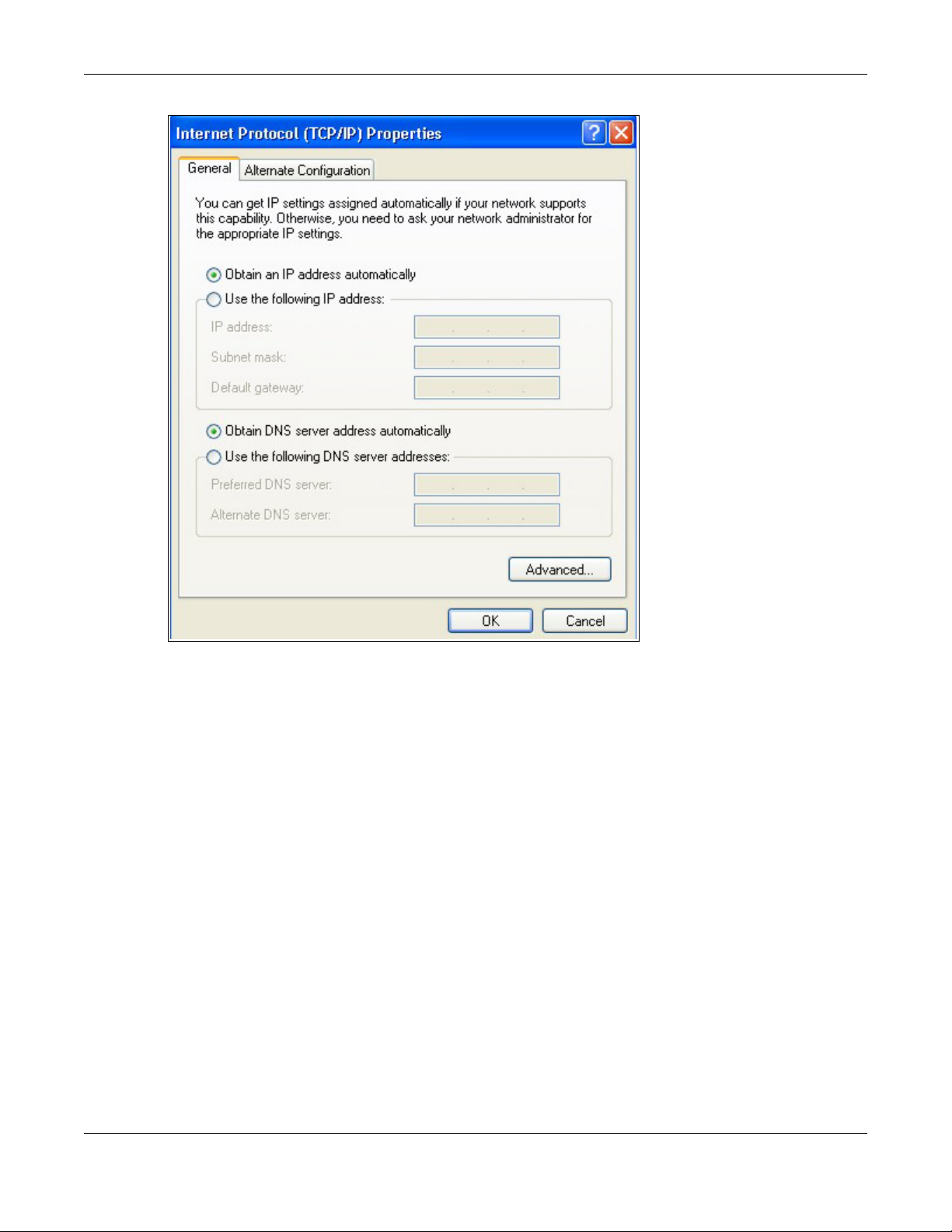
Appendix A Setting Up Your Computer’s IP Address
6 Select Obtain an IP address automatically if your network administrator or ISP assigns your IP
address dynamically.
Select Use the following IP Address and fill in the IP address, Subnet mask, and Default
gateway fields if you have a static IP address that was assigned to you by your network
administrator or ISP. You may also have to enter a Preferred DNS server and an Alternate DNS
server, if that information was provided.
7 Click OK to close the Internet Protocol (TCP/IP) Properties window.
8 Click OK to close the Local Area Connection Properties window.
Verifying Settings
1 Click Start > All Programs > Accessories > Command Prompt.
2 In the Command Prompt window, type "ipconfig" and then press [ENTER].
You can also go to Start > Control Panel > Network Connections, right-click a network
connection, click Status and then click the Support tab to view your IP address and connection
information.
WRE6505 User’s Guide
84
Page 85

Windows Vista
This section shows screens from Windows Vista Professional.
1 Click Start > Control Panel.
2 In the Control Panel, click the Network and Internet icon.
Appendix A Setting Up Your Computer’s IP Address
3 Click the Network and Sharing Center icon.
4 Click Manage network connections.
WRE6505 User’s Guide
85
Page 86
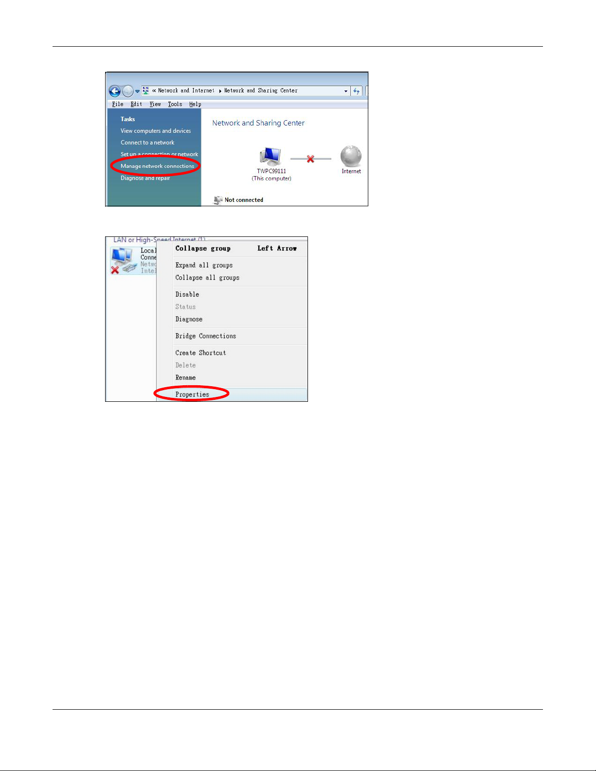
Appendix A Setting Up Your Computer’s IP Address
5 Right-click Local Area Connection and then select Properties.
Note: During this procedure, click Continue whenever Windows displays a screen saying
that it needs your permission to continue.
6 Select Internet Protocol Version 4 (TCP/IPv4) and then select Properties.
WRE6505 User’s Guide
86
Page 87
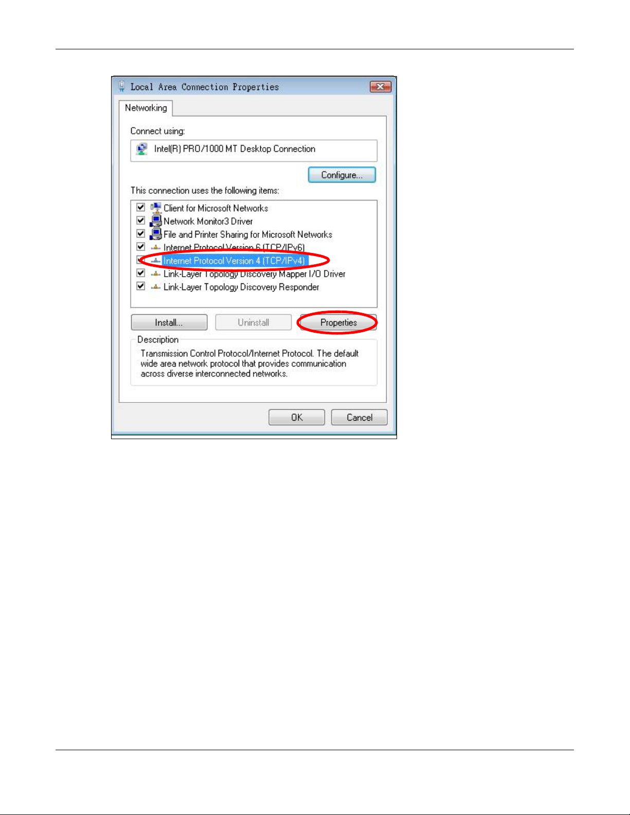
Appendix A Setting Up Your Computer’s IP Address
7 The Internet Protocol Version 4 (TCP/IPv4) Properties window opens.
WRE6505 User’s Guide
87
Page 88
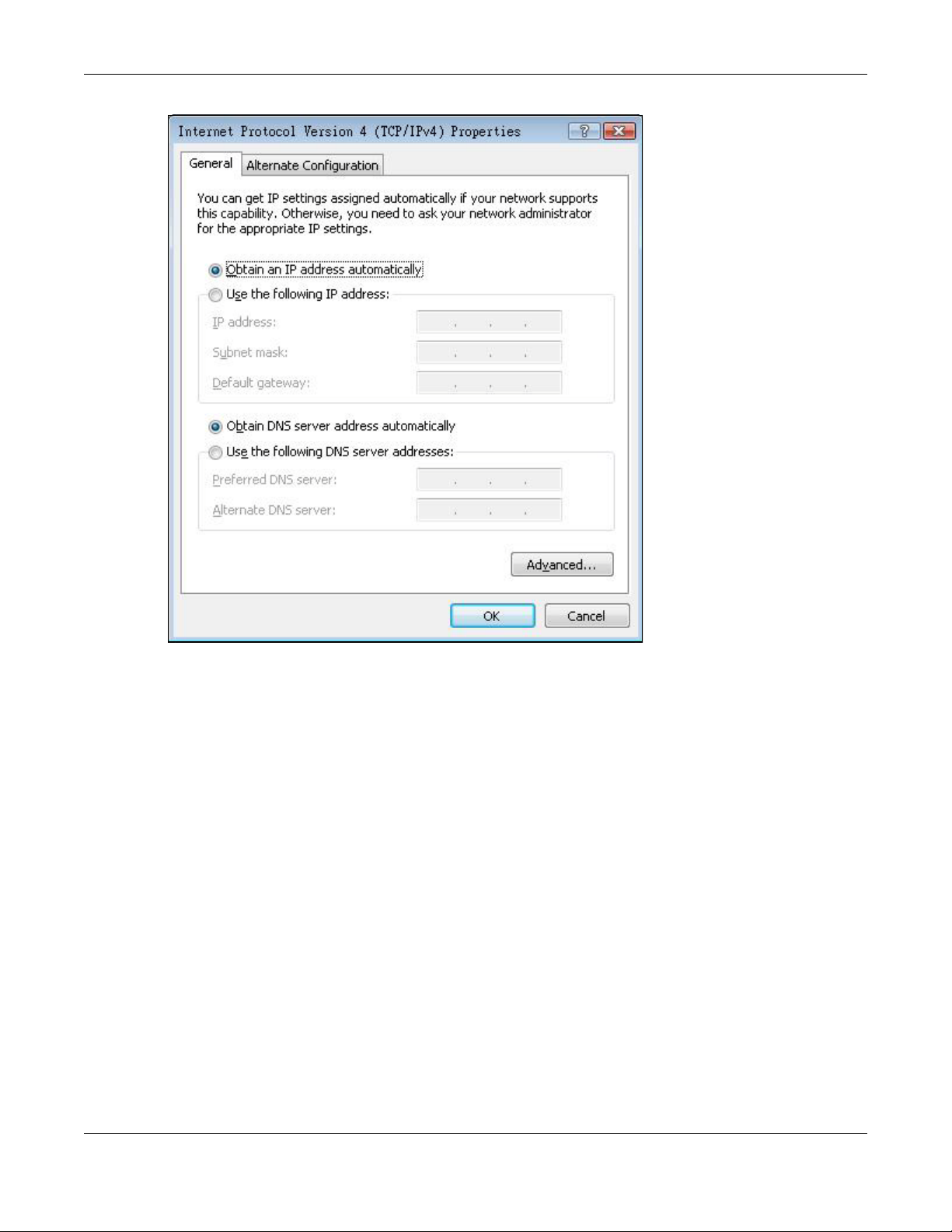
Appendix A Setting Up Your Computer’s IP Address
8 Select Obtain an IP address automatically if your network administrator or ISP assigns your IP
address dynamically.
Select Use the following IP Address and fill in the IP address, Subnet mask, and Default
gateway fields if you have a static IP address that was assigned to you by your network
administrator or ISP. You may also have to enter a Preferred DNS server and an Alternate DNS
server, if that information was provided.Click Advanced.
9 Click OK to close the Internet Protocol (TCP/IP) Properties window.
10 Click OK to close the Local Area Connection Properties window.
Verifying Settings
1 Click Start > All Programs > Accessories > Command Prompt.
2 In the Command Prompt window, type "ipconfig" and then press [ENTER].
You can also go to Start > Control Panel > Network Connections, right-click a network
connection, click Status and then click the Support tab to view your IP address and connection
information.
WRE6505 User’s Guide
88
Page 89
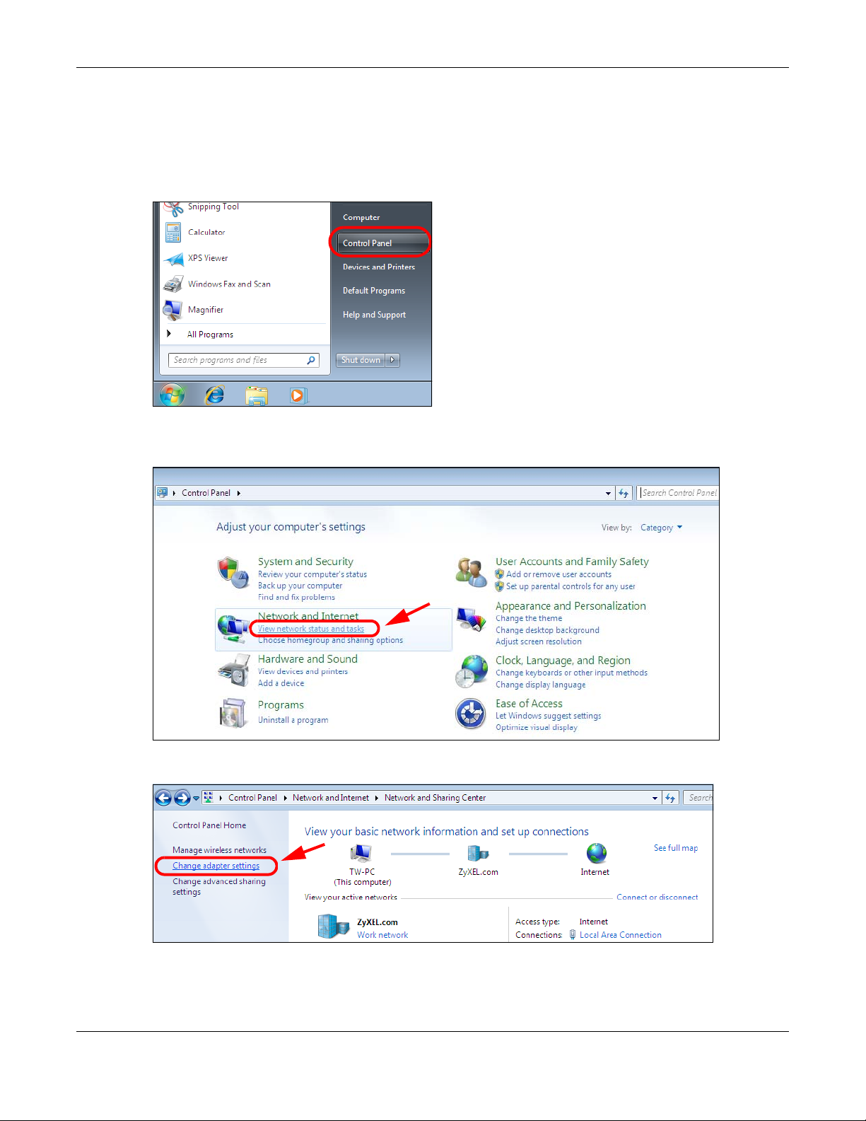
Windows 7
This section shows screens from Windows 7 Enterprise.
1 Click Start > Control Panel.
2 In the Control Panel, click View network status and tasks under the Network and Internet
category.
Appendix A Setting Up Your Computer’s IP Address
3 Click Change adapter settings.
4 Double click Local Area Connection and then select Properties.
WRE6505 User’s Guide
89
Page 90

Appendix A Setting Up Your Computer’s IP Address
Note: During this procedure, click Continue whenever Windows displays a screen saying
that it needs your permission to continue.
5 Select Internet Protocol Version 4 (TCP/IPv4) and then select Properties.
WRE6505 User’s Guide
90
Page 91

Appendix A Setting Up Your Computer’s IP Address
6 The Internet Protocol Version 4 (TCP/IPv4) Properties window opens.
WRE6505 User’s Guide
91
Page 92

Appendix A Setting Up Your Computer’s IP Address
7 Select Obtain an IP address automatically if your network administrator or ISP assigns your IP
address dynamically.
Select Use the following IP Address and fill in the IP address, Subnet mask, and Default
gateway fields if you have a static IP address that was assigned to you by your network
administrator or ISP. You may also have to enter a Preferred DNS server and an Alternate DNS
server, if that information was provided. Click Advanced if you want to configure advanced
settings for IP, DNS and WINS.
8 Click OK to close the Internet Protocol (TCP/IP) Properties window.
9 Click OK to close the Local Area Connection Properties window.
Verifying Settings
1 Click Start > All Programs > Accessories > Command Prompt.
2 In the Command Prompt window, type "ipconfig" and then press [ENTER].
3 The IP settings are displayed as follows.
WRE6505 User’s Guide
92
Page 93

Mac OS X: 10.3 and 10.4
The screens in this section are from Mac OS X 10.4 but can also apply to 10.3.
1 Click Apple > System Preferences.
Appendix A Setting Up Your Computer’s IP Address
2 In the System Preferences window, click the Network icon.
WRE6505 User’s Guide
93
Page 94

Appendix A Setting Up Your Computer’s IP Address
3 When the Network preferences pane opens, select Built-in Ethernet from the network
connection type list, and then click Configure.
4 For dynamically assigned settings, select Using DHCP from the Configure IPv4 list in the TCP/IP
tab.
WRE6505 User’s Guide
94
Page 95

Appendix A Setting Up Your Computer’s IP Address
5 For statically assigned settings, do the following:
•From the Configure IPv4 list, select Manually.
•In the IP Address field, type your IP address.
•In the Subnet Mask field, type your subnet mask.
•In the Router field, type the IP address of your device.
6 Click Apply Now and close the window.
Verifying Settings
Check your TCP/IP properties by clicking Applications > Utilities > Network Utilities, and then
selecting the appropriate Network Interface from the Info tab.
WRE6505 User’s Guide
95
Page 96
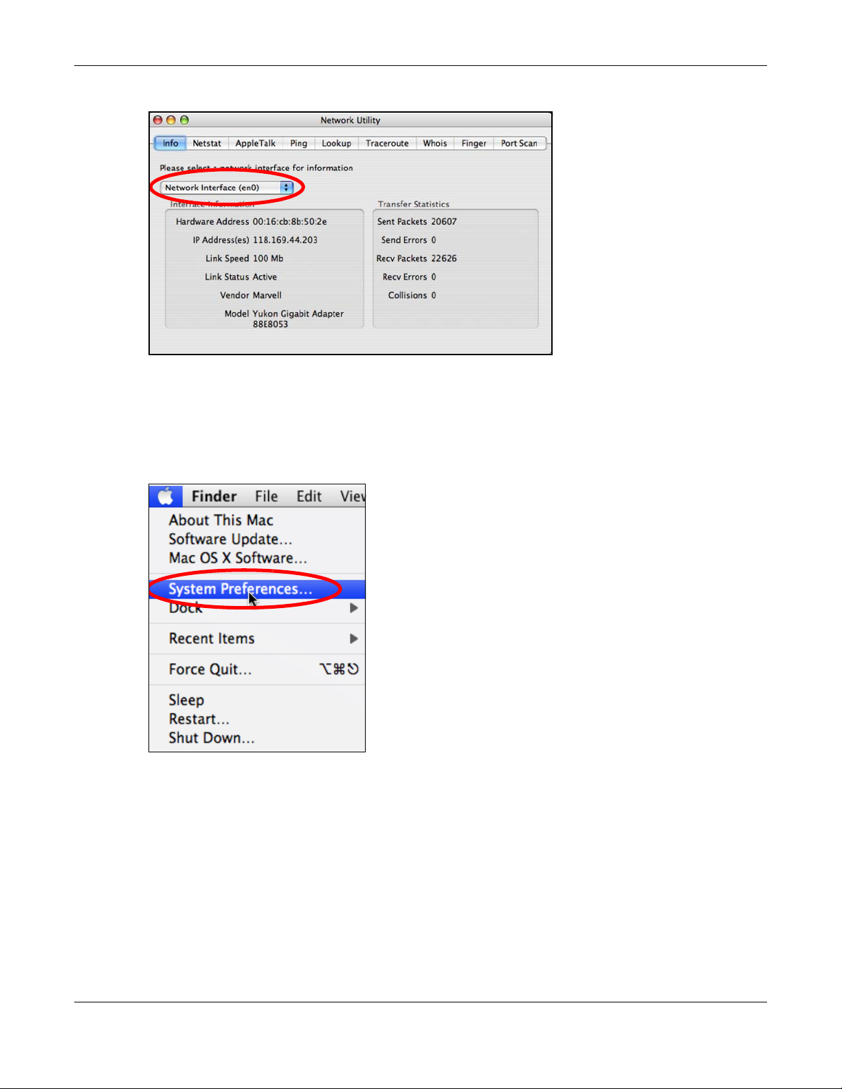
Figure 63 Mac OS X 10.4: Network Utility
Mac OS X: 10.5 and 10.6
The screens in this section are from Mac OS X 10.5 but can also apply to 10.6.
Appendix A Setting Up Your Computer’s IP Address
1 Click Apple > System Preferences.
2 In System Preferences, click the Network icon.
WRE6505 User’s Guide
96
Page 97

Appendix A Setting Up Your Computer’s IP Address
3 When the Network preferences pane opens, select Ethernet from the list of available connection
types.
4 From the Configure list, select Using DHCP for dynamically assigned settings.
5 For statically assigned settings, do the following:
•From the Configure list, select Manually.
•In the IP Address field, enter your IP address.
WRE6505 User’s Guide
97
Page 98
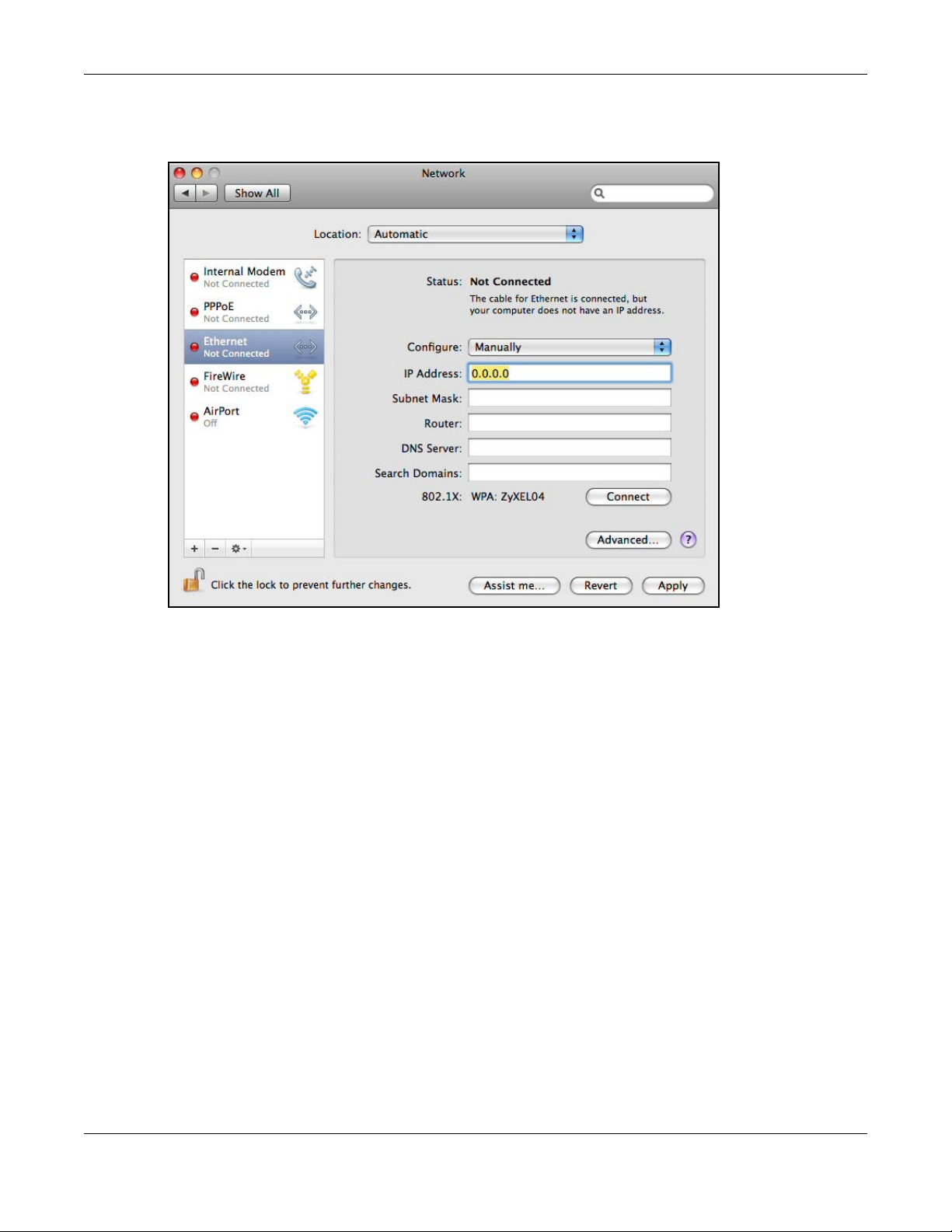
Appendix A Setting Up Your Computer’s IP Address
•In the Subnet Mask field, enter your subnet mask.
•In the Router field, enter the IP address of your WRE6505.
6 Click Apply and close the window.
Verifying Settings
Check your TCP/IP properties by clicking Applications > Utilities > Network Utilities, and then
selecting the appropriate Network interface from the Info tab.
WRE6505 User’s Guide
98
Page 99
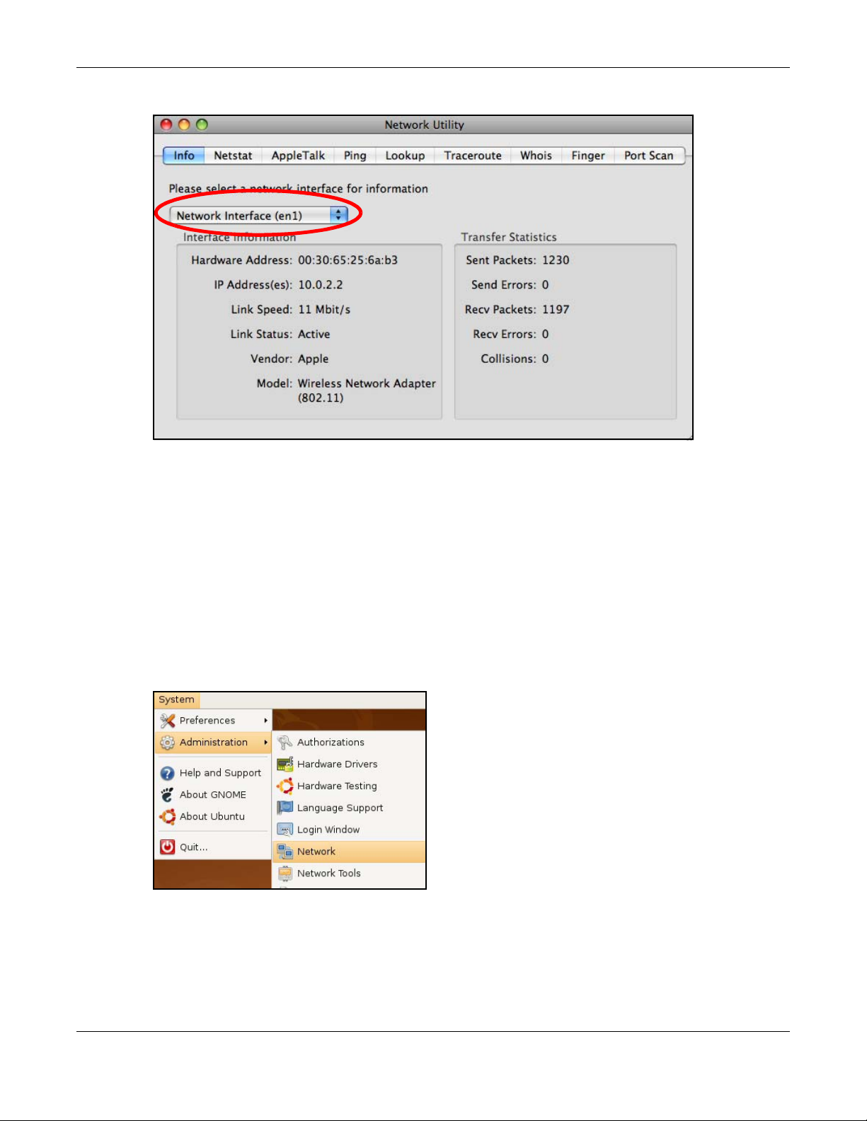
Appendix A Setting Up Your Computer’s IP Address
Figure 64 Mac OS X 10.5: Network Utility
Linux: Ubuntu 8 (GNOME)
This section shows you how to configure your computer’s TCP/IP settings in the GNU Object Model
Environment (GNOME) using the Ubuntu 8 Linux distribution. The procedure, screens and file
locations may vary depending on your specific distribution, release version, and individual
configuration. The following screens use the default Ubuntu 8 installation.
Note: Make sure you are logged in as the root administrator.
Follow the steps below to configure your computer IP address in GNOME:
1 Click System > Administration > Network.
2 When the Network Settings window opens, click Unlock to open the Authenticate window. (By
default, the Unlock button is greyed out until clicked.) You cannot make changes to your
configuration unless you first enter your admin password.
WRE6505 User’s Guide
99
Page 100

Appendix A Setting Up Your Computer’s IP Address
3 In the Authenticate window, enter your admin account name and password then click the
Authenticate button.
4 In the Network Settings window, select the connection that you want to configure, then click
Properties.
WRE6505 User’s Guide
100
 Loading...