


VES-1124
24-port QAM 2-band VDSL Switch
User’s Guide
July 2004
Version 3.50(LP.0)

VES-1124 User’s Guide
Copyright
Copyright © 2004 by ZyXEL Communications Corporation
The contents of this publication may not be reproduced in any part or as a whole, transcribed, stored in a retrieval
system, translated into any language, or transmitted in any form or by any means, electronic, mechanical, magnetic,
optical, chemical, photocopying, manual, or otherwise, without the prior written permission of ZyXEL
Communications Corporation.
Published by ZyXEL Communications Corporation. All rights reserved.
Disclaimer
ZyXEL does not assume any liability arising out of the application or use of any products, or software described
herein. Neither does it convey any license under its patent rights nor the patents rights of others. ZyXEL further
reserves the right to make changes in any products described herein without notice. This publication is subject to
change without notice.
Trademarks
Trademarks mentioned in this publication are used for identification purposes only and may be properties of their
respective owners.
ii Copyright

VES-1124 User’s Guide
Interference Statements and Warnings
FCC
Interference Statement:
This device complies with Part 15 of the FCC rules. Operation is subject to the following two conditions:
(1) This device may not cause harmful interference.
(2) This device must accept any interference received, including interference that may cause undesired operations.
FCC Warning!
This equipment has been tested and found to comply with the limits for a Class A digital device, pursuant to Part 15
of the FCC Rules. These limits are designed to provide reasonable protection against harmful interference in a
commercial environment. This equipment generates, uses, and can radiate radio frequency energy and, if not
installed and used in accordance with the instruction manual, may cause harmful interference to radio
communications. Operation of this equipment in a residential area is likely to cause harmful interference in which
case the user will be required to correct the interference at his own expense.
CE Mark Warning:
This is a class A product. In a domestic environment this product may cause radio interference in which case the
user may be required to take adequate measures.
Taiwanese BSMI (Bureau of Standards, Metrology and Inspection) A Warning:
Certifications
Refer to the product page at www.zyxel.com.
Interference Statements and Warnings iii

VES-1124 User’s Guide
Safety Warnings
For your safety, be sure to read and follow all warning notices and instructions.
To reduce the risk of fire, use only No. 26 AWG or larger telecommunication line cord.
Do NOT open the device or unit. Opening or removing covers can expose you to dangerous high voltage points
or other risks. ONLY qualified service personnel can service the device. Please contact your vendor for further
information.
Use ONLY the dedicated power supply for your device. Connect the power cord or power adaptor to the right
supply voltage, that is, 110V AC for North America or 230V AC for Europe.
Do NOT use the device if the power supply is damaged as it might cause electrocution.
If the power supply is damaged, remove it from the power outlet.
Do NOT attempt to repair the power supply. Contact your local vendor to order a new power supply.
Place connecting cables carefully so that that no one will step on them or stumble over them. Do NOT allow
anything to rest on the power cord and do NOT locate the product where anyone can walk on the power cord.
If you wall mount your device, make sure that no electrical, gas or water pipes will be damaged.
Do NOT install nor use your device during a thunderstorm. There may be a remote risk of electric shock from
lightning.
Do NOT expose your device to dampness, dust or corrosive liquids.
Do NOT use this product near water, for example, in a wet basement or near a swimming pool.
Make sure to connect the cables to the correct ports.
Do NOT obstruct the device ventilation slots, as insufficient airflow may harm your device.
Do NOT store things on the device.
Connect ONLY suitable accessories to the device.
iv Safety Warnings

VLC1124A User’s Guide
ZyXEL Limited Warranty
ZyXEL warrants to the original end user (purchaser) that this product is free from any defects in materials or
workmanship for a period of up to two (2) years from the date of purchase. During the warranty period and upon
proof of purchase, should the product have indications of failure due to faulty workmanship and/or materials,
ZyXEL will, at its discretion, repair or replace the defective products or components without charge for either parts
or labor and to whatever extent it shall deem necessary to restore the product or components to proper operating
condition. Any replacement will consist of a new or re-manufactured functionally equivalent product of equal
value, and will be solely at the discretion of ZyXEL. This warranty shall not apply if the product is modified,
misused, tampered with, damaged by an act of God, or subjected to abnormal working conditions.
Note
Repair or replacement, as provided under this warranty, is the exclusive remedy of the purchaser. This warranty is
in lieu of all other warranties, express or implied, including any implied warranty of merchantability or fitness for a
particular use or purpose. ZyXEL shall in no event be held liable for indirect or consequential damages of any kind
of character to the purchaser.
To obtain the services of this warranty, contact ZyXEL's Service Center for your Return Material Authorization
number (RMA). Products must be returned Postage Prepaid. It is recommended that the unit be insured when
shipped. Any returned products without proof of purchase or those with an out-dated warranty will be repaired or
replaced (at the discretion of ZyXEL) and the customer will be billed for parts and labor. All repaired or replaced
products will be shipped by ZyXEL to the corresponding return address, Postage Paid. This warranty gives you
specific legal rights, and you may also have other rights that vary from country to country.
ZyXEL Limited Warranty v

VES-1124 User’s Guide
Customer Support
If you have questions about your ZyXEL product or desire assistance, contact ZyXEL Communications
Corporation offices worldwide, in one of the following ways:
Contacting Customer Support
When you contact your customer support representative, have the following information ready:
♦ Product model and serial number.
♦ Firmware version information.
♦ Warranty information.
♦ Date you received your product.
♦ Brief description of the problem and the steps you took to solve it.
LOCATION
WORLDWIDE
SUPPORT E-MAIL TELEPHONE1 WEB SITE METHOD
SALES E-MAIL FAX1 FTP SITE
support@zyxel.com.tw +886-3-578-3942 www.zyxel.com
sales@zyxel.com.tw
support@zyxel.com +1-800-255-4101
sales@zyxel.com
support@zyxel.de +49-2405-6909-0 www.zyxel.de GERMANY
sales@zyxel.de
support@zyxel.es +34 902 195 420 SPAIN
sales@zyxel.es
support@zyxel.dk +45 39 55 07 00 www.zyxel.dk DENMARK
sales@zyxel.dk
support@zyxel.no +47 22 80 61 80 www.zyxel.no NORWAY
sales@zyxel.no
support@zyxel.se +46 31 744 7700 www.zyxel.se SWEDEN
sales@zyxel.se
support@zyxel.fi +358-9-4780-8411 www.zyxel.fi FINLAND
sales@zyxel.fi
+886-3-578-2439 ftp.europe.zyxel.com
+1-714-632-0882
+1-714-632-0858 ftp.us.zyxel.com
+49-2405-6909-99
+33 (0)4 72 52 97 97 FRANCE info@zyxel.fr
+33 (0)4 72 52 19 20
+34 913 005 345
+45 39 55 07 07
+47 22 80 61 81
+46 31 744 7701
+358-9-4780 8448
www.europe.zyxel.com
ftp.zyxel.com
www.us.zyxel.com NORTH AMERICA
www.zyxel.fr ZyXEL France
www.zyxel.es
ZyXEL Communications
ZyXEL Communications Corp.
6 Innovation Road II
Science Park
Hsinchu 300
Taiwan
ZyXEL Communications Inc.
1130 N. Miller St.
Anaheim
CA 92806-2001
U.S.A.
ZyXEL Deutschland GmbH. Adenauerstr.
20/A2 D-52146
Wuerselen
Germany
1 rue des Vergers
Bat. 1 / C
69760 Limonest
France
Alejandro Villegas 33
1º, 28043 Madrid
Spain
ZyXEL Communications A/S
Columbusvej 5
2860 Soeborg
Denmark
ZyXEL Communications A/S
Nils Hansens vei 13
0667 Oslo
Norway
ZyXEL Communications A/S
Sjöporten 4, 41764 Göteborg
Sweden
ZyXEL Communications Oy
Malminkaari 10
00700 Helsinki
Finland
REGULAR MAIL
1
“+” is the (prefix) number you enter to make an international telephone call.
vi Customer Support

VLC1124A User’s Guide
Table of Contents
Copyright .................................................................................................................................................................... ii
Interference Statements and Warnings................................................................................................................... iii
Safety Warnings ........................................................................................................................................................ iv
ZyXEL Limited Warranty ........................................................................................................................................ v
Customer Support..................................................................................................................................................... vi
Table of Contents ..................................................................................................................................................... vii
List of Figures............................................................................................................................................................. x
List of Tables ........................................................................................................................................................... xiii
Preface....................................................................................................................................................................... xv
Chapter 1 Getting to know the VES .................................................................................................................. 1-1
1.1 Overview ............................................................................................................................................... 1-1
1.2 Features1 ............................................................................................................................................... 1-1
1.3 Applications ..........................................................................................................................................1-4
Chapter 2 Hardware Installation....................................................................................................................... 2-1
2.1 Installation Scenarios ............................................................................................................................ 2-1
2.2 Desktop Installation Procedure .............................................................................................................2-1
2.3 Rack-Mounted Installation.................................................................................................................... 2-2
Chapter 3 Hardware Connections ..................................................................................................................... 3-1
3.1 Front Panel ............................................................................................................................................ 3-1
3.2 Front Panel LEDs.................................................................................................................................. 3-2
3.3 Rear Panel .............................................................................................................................................3-3
Chapter 4 Introducing the Web Configurator ................................................................................................. 4-1
4.1 Introduction ........................................................................................................................................... 4-1
4.2 System Login ........................................................................................................................................ 4-1
4.3 Status Screen .........................................................................................................................................4-1
4.4 Switch Lockout .....................................................................................................................................4-6
4.5 Resetting the Switch.............................................................................................................................. 4-6
Chapter 5 Status, Port Details and VDSL Summary....................................................................................... 5-1
5.1 Overview ............................................................................................................................................... 5-1
5.2 Port Status .............................................................................................................................................5-1
Chapter 6 Basic Setting ...................................................................................................................................... 6-1
6.1 Introducing The Basic Setting Screens .................................................................................................6-1
6.2 System Information............................................................................................................................... 6-1
6.3 General Setup ........................................................................................................................................ 6-4
6.4 Introduction to VLANs .........................................................................................................................6-5
6.5 IGMP Snooping .................................................................................................................................... 6-6
6.6 Switch Setup Screen.............................................................................................................................. 6-6
6.7 IP Setup ................................................................................................................................................. 6-9
6.8 Port Setup ............................................................................................................................................ 6-10
6.9 VDSL Parameters................................................................................................................................ 6-13
6.10 VDSL Common Setup ........................................................................................................................6-14
6.11 VDSL Profile Setup ............................................................................................................................6-14
6.12 Viewing and Editing VDSL Profiles................................................................................................... 6-16
Table of Contents vii

VES-1124 User’s Guide
Chapter 7 VLAN .................................................................................................................................................7-1
7.1 Introduction to IEEE 802.1Q Tagged VLAN........................................................................................ 7-1
7.2 802.1Q VLAN ....................................................................................................................................... 7-3
7.3 Introduction to Port-based VLANs .....................................................................................................7-10
Chapter 8 Static MAC Forward Setup.............................................................................................................. 8-1
8.1 Introduction to Static MAC Forward Setup ..........................................................................................8-1
8.2 Configuring Static MAC Forwarding....................................................................................................8-1
8.3 Viewing and Editing Static MAC Forwarding Rules............................................................................8-2
Chapter 9 Spanning Tree Protocol ....................................................................................................................9-1
9.1 Introduction to Spanning Tree Protocol (STP)...................................................................................... 9-1
9.2 STP Terminology ..................................................................................................................................9-1
9.3 How STP Works.................................................................................................................................... 9-1
9.4 STP Status .............................................................................................................................................9-2
Chapter 10 Bandwidth Control........................................................................................................................ 10-1
10.1 Introduction to Bandwidth Control .....................................................................................................10-1
Chapter 11 Broadcast Storm Control..............................................................................................................11-1
11.1 Introducing Broadcast Storm Control .................................................................................................11-1
11.2 Configuring Broadcast Storm Control.................................................................................................11-1
Chapter 12 Mirroring .......................................................................................................................................12-1
12.1 Introduction to Port Mirroring.............................................................................................................12-1
12.2 Port Mirroring Configuration ..............................................................................................................12-1
Chapter 13 Link Aggregation...........................................................................................................................13-1
13.1 Introduction to Link Aggregation........................................................................................................13-1
13.2 Link Aggregation Protocol Status ....................................................................................................... 13-2
13.3 Link Aggregation Setup ......................................................................................................................13-3
Chapter 14 Port Authentication.......................................................................................................................14-1
14.1 Introduction to Authentication ............................................................................................................14-1
14.2 Configuring Port Authentication ......................................................................................................... 14-1
Chapter 15 Port Security .................................................................................................................................. 15-1
15.1 About Port Security.............................................................................................................................15-1
15.2 Port Security Setup..............................................................................................................................15-1
Chapter 16 Access Control ...............................................................................................................................16-1
16.1 About Access Control..........................................................................................................................16-1
16.2 Access Control Overview.................................................................................................................... 16-1
16.3 About SNMP ....................................................................................................................................... 16-2
16.4 Service Access Control........................................................................................................................16-6
16.5 Remote Management...........................................................................................................................16-6
Chapter 17 Queuing Method............................................................................................................................17-1
17.1 Introduction to Queuing ......................................................................................................................17-1
17.2 Configuring Queuing...........................................................................................................................17-1
17.3 Weighted Round Robin Scheduling Example.....................................................................................17-2
Chapter 18 Routing Protocol............................................................................................................................ 18-1
18.1 Static Route .........................................................................................................................................18-1
Chapter 19 Maintenance...................................................................................................................................19-1
19.1 Maintenance ........................................................................................................................................19-1
viii Table of Contents

VLC1124A User’s Guide
19.2 Firmware Upgrade ..............................................................................................................................19-1
19.3 Restore a Configuration File ...............................................................................................................19-2
19.4 Backing Up a Configuration File ........................................................................................................19-2
19.5 Load Factory Defaults......................................................................................................................... 19-3
19.6 Reboot System ....................................................................................................................................19-4
19.7 Command Line FTP............................................................................................................................ 19-4
Chapter 20 Diagnostic....................................................................................................................................... 20-1
20.1 Diagnostic ...........................................................................................................................................20-1
Chapter 21 Cluster Management..................................................................................................................... 21-1
21.1 Introduction to Cluster Management................................................................................................... 21-1
21.2 Cluster Management Status................................................................................................................. 21-2
21.3 Configuring Cluster Management....................................................................................................... 21-4
Chapter 22 MAC Table .................................................................................................................................... 22-1
22.1 Introduction to MAC Table................................................................................................................. 22-1
22.2 Viewing MAC Table........................................................................................................................... 22-2
Chapter 23 ARP Table...................................................................................................................................... 23-1
23.1 Introduction to ARP Table .................................................................................................................. 23-1
23.2 Viewing ARP Table ............................................................................................................................ 23-1
Chapter 24 Introduction to CLI................................................................................................................... 24-1
24.1 Command Line Interface Overview ....................................................................................................24-1
24.2 Command Summary............................................................................................................................ 24-2
Chapter 25 Command Examples ................................................................................................................. 25-1
25.1 Commonly Used Commands Overview.............................................................................................. 25-1
25.2 sys Commands .................................................................................................................................... 25-1
25.3 sys cluster Commands ......................................................................................................................... 25-3
25.4 ip Commands ...................................................................................................................................... 25-5
25.5 vdsl Commands ................................................................................................................................... 25-6
25.6 Enabling rstp on a VDSL Port............................................................................................................. 25-8
Chapter 26 IEEE 802.1Q Tagged VLAN Commands................................................................................ 26-1
26.1 IEEE 802.1Q Tagged VLAN Overview.............................................................................................. 26-1
26.2 Filtering Databases .............................................................................................................................. 26-1
26.3 Configuring Tagged VLAN ................................................................................................................ 26-2
26.4 IEEE VLAN1Q Tagged VLAN Configuration Commands................................................................ 26-3
26.5 vlan1q svlan active ..............................................................................................................................26-8
26.6 vlan1q svlan inactive ........................................................................................................................... 26-8
26.7 vlan1q svlan list................................................................................................................................... 26-8
Appendix A Troubleshooting..........................................................................................................................A
Appendix B Product Specifications................................................................................................................E
Index............................................................................................................................................................................. i
Table of Contents ix

VES-1124 User’s Guide
List of Figures
Figure 1-1 MTU Application ......................................................................................................................................................1-4
Figure 1-2 Curbside Application................................................................................................................................................. 1-5
Figure 2-1 Attaching Rubber Feet............................................................................................................................................... 2-1
Figure 2-2 Attaching Mounting Brackets and Screws................................................................................................................. 2-2
Figure 2-3 Mounting the VES to an EIA standard 19-inch rack .................................................................................................2-2
Figure 3-1 VES-1124 Front Panel...............................................................................................................................................3-1
Figure 3-2 VES-1124 Back Panel ...............................................................................................................................................3-3
Figure 4-1 Web Configurator: login............................................................................................................................................ 4-1
Figure 4-2 Web Configurator Status Screen................................................................................................................................ 4-2
Figure 4-3 Web Configurator: Change Password at Login .........................................................................................................4-6
Figure 4-4 Resetting the VES Via Command.............................................................................................................................. 4-7
Figure 4-5 Uploading the Default Configuration File Via Console Port..................................................................................... 4-8
Figure 4-6 Web Configurator: Logout Screen............................................................................................................................. 4-8
Figure 5-1 Status ......................................................................................................................................................................... 5-2
Figure 5-2 Status: VDSL Summary ............................................................................................................................................5-4
Figure 5-3 Status: VDSL Port Details ......................................................................................................................................... 5-5
Figure 5-4 Status: Port Details (Ethernet)................................................................................................................................... 5-9
Figure 6-1 System Info ...............................................................................................................................................................6-2
Figure 6-2 General Setup ............................................................................................................................................................ 6-4
Figure 6-3 Switch Setup.............................................................................................................................................................. 6-7
Figure 6-4 Port Setup ................................................................................................................................................................ 6-11
Figure 6-5 VDSL Common Setup............................................................................................................................................. 6-14
Figure 6-6 VDSL Profile Setup................................................................................................................................................. 6-15
Figure 6-7 VDSL Profile Setup: Summary Table...................................................................................................................... 6-16
Figure 7-1 Selecting a VLAN Type ............................................................................................................................................ 7-3
Figure 7-2 802.1Q VLAN Status ................................................................................................................................................ 7-3
Figure 7-3 802.1Q VLAN Port Settings......................................................................................................................................7-5
Figure 7-4 802.1Q Static VLAN.................................................................................................................................................7-7
Figure 7-5 Static VLAN: Summary Table................................................................................................................................... 7-8
Figure 7-6 VID1 Example Screen............................................................................................................................................... 7-9
Figure 7-7 Port Based VLAN Setup (All Connected)............................................................................................................... 7-11
Figure 7-8 Port Based VLAN Setup (Port Isolation) ................................................................................................................7-12
Figure 8-1 Static MAC Forwarding ............................................................................................................................................ 8-1
Figure 8-2 Static MAC Forwarding: Summary Table .................................................................................................................8-2
Figure 9-1 Spanning Tree Protocol: Status..................................................................................................................................9-3
Figure 9-2 Spanning Tree Protocol: Configuration..................................................................................................................... 9-5
Figure 10-1 Bandwidth Control ................................................................................................................................................ 10-1
Figure 11-1 Broadcast Storm Control ....................................................................................................................................... 11-1
Figure 12-1 Mirroring ............................................................................................................................................................... 12-2
Figure 13-1 Aggregation ID ...................................................................................................................................................... 13-2
Figure 13-2 Link Aggregation: Link Aggregation Protocol Status ........................................................................................... 13-2
Figure 13-3 Link Aggregation: Configuration ..........................................................................................................................13-3
Figure 14-1 RADIUS Server..................................................................................................................................................... 14-1
x List of Figures

VLC1124A User’s Guide
Figure 14-2 Port Authentication................................................................................................................................................14-2
Figure 14-3 Port Authentication: RADIUS ...............................................................................................................................14-2
Figure 14-4 Port Authentication: 802.1x...................................................................................................................................14-3
Figure 15-1 Port Security ..........................................................................................................................................................15-2
Figure 16-1 Access Control.......................................................................................................................................................16-1
Figure 16-2 Console Port Priority .............................................................................................................................................16-1
Figure 16-3 SNMP Management Model ...................................................................................................................................16-2
Figure 16-4 Access Control: SNMP ..........................................................................................................................................16-4
Figure 16-5 Access Control: Logins.......................................................................................................................................... 16-5
Figure 16-6 Access Control: Service Access Control................................................................................................................16-6
Figure 16-7 Access Control: Remote Management...................................................................................................................16-7
Figure 17-1 Queuing Method ....................................................................................................................................................17-2
Figure 17-2 Weighted Round Robin Scheduling Configuration Example.................................................................................17-3
Figure 17-3 Weighted Round Robin Scheduling Ratio Example..............................................................................................17-3
Figure 18-1 Static Routing ........................................................................................................................................................18-1
Figure 18-2 Static Routing: Summary Table.............................................................................................................................18-2
Figure 19-1 Maintenance...........................................................................................................................................................19-1
Figure 19-2 Firmware Upgrade................................................................................................................................................. 19-2
Figure 19-3 Restore Configuration............................................................................................................................................19-2
Figure 19-4 Backup Configuration............................................................................................................................................19-3
Figure 19-5 Confirm Load factory Defaults..............................................................................................................................19-3
Figure 19-6 Restart Switch After Load Factory Defaults..........................................................................................................19-3
Figure 19-7 Confirm Restart the Switch....................................................................................................................................19-4
Figure 20-1 Diagnostic..............................................................................................................................................................20-1
Figure 21-1 Clustering Application Example............................................................................................................................21-1
Figure 21-2 Cluster Management Status ...................................................................................................................................21-2
Figure 21-3 Cluster Member Web Configuration Screen Example...........................................................................................21-3
Figure 21-4 Example: Uploading Firmware to a Cluster Member Switch................................................................................21-4
Figure 21-5 Configuring Cluster Management .........................................................................................................................21-5
Figure 22-1 MAC Table Filtering Flowchart.............................................................................................................................22-1
Figure 22-2 MAC Table ............................................................................................................................................................22-2
Figure 23-1 ARP Table..............................................................................................................................................................23-1
Figure 24-1 CLI Help: Sample Output......................................................................................................................................24-2
Figure 25-1 sys log disp Command Example............................................................................................................................25-1
Figure 25-2 sys version Command Example.............................................................................................................................25-2
Figure 25-3 sys sw vlan1q vlan list Command Example ..........................................................................................................25-2
Figure 25-4 sys sw pktcnt Command Example.........................................................................................................................25-3
Figure 25-5 sys sw mac list Command Example ......................................................................................................................25-3
Figure 25-6 sys cluster status Command Example....................................................................................................................25-4
Figure 25-7 sys cluster showMember Command Example .......................................................................................................25-4
Figure 25-8 sys cluster status Command Example....................................................................................................................25-5
Figure 25-9 IP PING Command Example.................................................................................................................................25-5
Figure 25-10 ip route status Command Example ......................................................................................................................25-6
Figure 25-11 ip arp status Command Example .........................................................................................................................25-6
Figure 25-12 ip dhcp Command Examples...............................................................................................................................25-6
List of Figures xi

VES-1124 User’s Guide
Figure 25-13 vdsl profile list Command Example .................................................................................................................... 25-7
Figure 25-14 vdsl profile apply Command Example................................................................................................................ 25-7
Figure 25-15 vdsl port status display Command Example........................................................................................................ 25-8
Figure 25-16 vdsl setmode Command Example ....................................................................................................................... 25-8
Figure 26-1 Tagged VLAN Configuration and Activation Example.........................................................................................26-2
Figure 26-2 CPU VLAN Configuration and Activation Example ............................................................................................26-2
Figure 26-3 Deleting Default VLAN Example......................................................................................................................... 26-3
Figure 26-4 GARP STATUS Command Example ....................................................................................................................26-3
Figure 26-5 garp timer Command Example.............................................................................................................................. 26-4
Figure 26-6 garp status Command Example............................................................................................................................. 26-4
Figure 26-7 vlan1q port status Command Example.................................................................................................................. 26-5
Figure 26-8 vlan1q port default vid Command Example.......................................................................................................... 26-5
Figure 26-9 vlan1q port accept Command Example................................................................................................................. 26-6
Figure 26-10 vlan1q port gvrp Command Example.................................................................................................................. 26-6
Figure 26-11 vlan1q svlan cpu Command Example .................................................................................................................26-6
Figure 26-12 Modifying the Static VLAN Example................................................................................................................. 26-7
Figure 26-13 vlan1q svlan delentry Command Example.......................................................................................................... 26-8
Figure 26-14 vlan1q svlan list Command Example .................................................................................................................. 26-9
Figure 26-15 vlan1q status Command Example ....................................................................................................................... 26-9
xii List of Figures

VLC1124A User’s Guide
List of Tables
Table 3-1 VES-1124: Front Panel................................................................................................................................................3-1
Table 3-2 LED Descriptions........................................................................................................................................................3-2
Table 4-1 Navigation Panel Sub-links Overview ........................................................................................................................4-3
Table 4-2 Web Configurator Screens Overview..........................................................................................................................4-3
Table 4-3 Navigation Panel Sub-link Descriptions .....................................................................................................................4-4
Table 5-1 Status...........................................................................................................................................................................5-3
Table 5-2 Status: VDSL Port Details...........................................................................................................................................5-6
Table 5-3 Status: Port Details (Ethernet)...................................................................................................................................5-10
Table 6-1 System Info .................................................................................................................................................................6-2
Table 6-2 General Setup ..............................................................................................................................................................6-4
Table 6-3 Switch Setup................................................................................................................................................................6-7
Table 6-4 IP Setup .......................................................................................................................................................................6-9
Table 6-5 Port Setup ..................................................................................................................................................................6-12
Table 6-6 VDSL Common Setup...............................................................................................................................................6-14
Table 6-7 VDSL Profile Setup...................................................................................................................................................6-16
Table 6-8 VDSL Profile Setup: Summary Table .......................................................................................................................6-17
Table 7-1 GARP Terminology .....................................................................................................................................................7-2
Table 7-2 802.1Q VLAN Status ..................................................................................................................................................7-3
Table 7-3 802.1Q VLAN Port Settings........................................................................................................................................7-6
Table 7-4 802.1Q Static VLAN...................................................................................................................................................7-8
Table 7-5 Static VLAN: Summary Table.....................................................................................................................................7-8
Table 7-6 Port Based VLAN Setup ...........................................................................................................................................7-12
Table 8-1 Static MAC Forwarding ..............................................................................................................................................8-1
Table 8-2 Static MAC Forwarding: Summary Table ...................................................................................................................8-2
Table 9-1 STP Path Costs............................................................................................................................................................9-1
Table 9-2 STP Port States............................................................................................................................................................9-2
Table 9-3 Spanning Tree Protocol: Status ...................................................................................................................................9-3
Table 9-4 Spanning Tree Protocol: Configuration.......................................................................................................................9-6
Table 10-1 Bandwidth Control ..................................................................................................................................................10-2
Table 11-1 Broadcast Storm Control .........................................................................................................................................11-1
Table 12-1 Mirroring .................................................................................................................................................................12-3
Table 13-1 Link Aggregation: Link Aggregation Protocol Status .............................................................................................13-3
Table 13-2 Link Aggregation: Configuration............................................................................................................................13-3
Table 14-1 Port Authentication: RADIUS.................................................................................................................................14-2
Table 14-2 Port Authentication: 802.1x.....................................................................................................................................14-4
Table 15-1 Port Security............................................................................................................................................................ 15-2
Table 16-1 Access Control Summary ........................................................................................................................................ 16-1
Table 16-2 SNMP Commands...................................................................................................................................................16-2
Table 16-3 SNMP Traps ............................................................................................................................................................16-3
Table 16-4 Access Control: SNMP............................................................................................................................................16-4
Table 16-5 Access Control: Logins ...........................................................................................................................................16-5
Table 16-6 Access Control: Service Access Control .................................................................................................................16-6
Table 16-7 Access Control: Remote Management ....................................................................................................................16-7
List of Tables xiii

VES-1124 User’s Guide
Table 17-1 Queuing Method .....................................................................................................................................................17-2
Table 18-1 Static Routing.......................................................................................................................................................... 18-1
Table 18-2 Static Routing: Summary Table .............................................................................................................................. 18-2
Table 19-1 Filename Conventions.............................................................................................................................................19-4
Table 19-2 General Commands for GUI-based FTP Clients..................................................................................................... 19-5
Table 20-1 Diagnostic ...............................................................................................................................................................20-1
Table 21-1 ZyXEL Clustering Management Specifications......................................................................................................21-1
Table 21-2 Cluster Management Status.....................................................................................................................................21-2
Table 21-3 FTP Upload to Cluster member Example ...............................................................................................................21-4
Table 21-4 Configuring Cluster Management........................................................................................................................... 21-5
Table 22-1 MAC Table.............................................................................................................................................................. 22-2
Table 23-1 ARP Table ...............................................................................................................................................................23-2
Table 24-1 Command Summary: sys ........................................................................................................................................ 24-2
Table 24-2 Command Summary: sys sw................................................................................................................................... 24-6
Table 24-3 Command Summary: exit ..................................................................................................................................... 24-11
Table 24-4 Command Summary: ip ........................................................................................................................................ 24-12
Table 24-5 Command Summary: vdsl..................................................................................................................................... 24-13
Table 24-6 Command Summary: config ................................................................................................................................. 24-15
Table 23-1 Troubleshooting Data Transmission............................................................................................................................ A
Table 23-2 Troubleshooting a Non-Constant VDSL LED .............................................................................................................B
Table 23-3 Troubleshooting the SYNC-rate...................................................................................................................................B
Table 23-4 Troubleshooting the VES’s Configured Settings..........................................................................................................B
Table 23-5 Troubleshooting the Password .....................................................................................................................................B
Table 23-6 Troubleshooting a Remote Server................................................................................................................................C
Table 23-7 Troubleshooting Connecting to the Switch ..................................................................................................................C
xiv List of Tables

VLC1124A User’s Guide
Preface
About this User’s Manual
This user’s guide gives hardware specifications and explains web configurator and command line configuration,
management, and troubleshooting for the switch.
Online Registration
Register your ZyXEL product online at www.zyxel.com for free future product updates and information.
General Syntax Conventions
Mouse action sequences are denoted using a comma. For example, click Start, Settings, Control Panel,
Network means first you click Start, click or move the mouse pointer over Settings, then click or move
the mouse pointer over Control Panel and finally click (or double-click) Network.
“Enter” means for you to type one or more characters. “Select” or “Choose” means for you to use one of
the predefined choices.
Predefined choices are in Bold Arial font.
Button and field labels, links and screen names in are in Bold Times New Roman font.
A single keystroke is in Arial font and enclosed in square brackets. [ENTER] means the Enter, or carriage
return key; [ESC] means the Escape key and [SPACE BAR] means the Space Bar.
For brevity’s sake, we will use “e.g.,” as shorthand for “for instance”, and “i.e.,” for “that is” or “in other
words”.
Naming Conventions
• The VES-1124 24-port QAM 2-band VDSL Switch may be referred to as the VES-1124, the VES, the
switch or, simply, as the device.
• This user’s guide refers an Ethernet device as a switch in general for feature background information.
Related Documentation
Web Configurator Online Help
Embedded web help for descriptions of individual screens and supplementary information.
Glossary and ZyXEL Web Site
Please refer to www.zyxel.com for an online glossary of networking terms or the ZyXEL download library for
additional support documentation.
Preface xv

VES-1124 User’s Guide
Firmware Naming Conventions
A firmware version includes the network operating system platform version, model code and release number as
shown in the following example.
Firmware Version: V3.50(LP.0)
“V3.50” is the network operating system platform version.
“LP” is the model code.
“0” is this firmware’s release number. This varies as new firmware is released. Your firmware’s release
number may not match what is displayed in this User’s Guide.
.
xvi Preface

Getting Ready
Part I:
Getting Ready
This part acquaints you with the features and applications of the VES-1124, instructs you how to
make the hardware connections, understand the front panel LEDs.
I


VES-1124 User’s Guide
Chapter 1
Getting to know the VES
This chapter describes the key features, benefits and applications of the VES-1124.
1.1 Overview
The VES-1124 is a stand-alone layer-2 VDSL over Ethernet switch with two Telco-50 connector port for 24 VDSL
and 24 POTS/ISDN connections. The VES-1124 also comes with two 10/100Base-TX uplink ports.
With its built-in web configurator, managing and configuring the switch is easy. From cabinet management to portlevel control and monitoring, you can visually configure and manage your network via the web browser. Just click
your mouse instead of typing cryptic command strings. In addition, the switch can also be managed via Telnet, the
console port, or third-party SNMP management
1.2 Features1
The next two sections describe the hardware and firmware features of the VES.
1.2.1 Hardware Features
QAM Modulation
The VES, combined with the Prestige 841 VDSL modem, provides service providers a QAM (quadrature amplitude
modulation)-based VDSL solution.
Band Plan Support
The VES supports various VDSL band plans (ETSI, ANSI/ETSI and 10 BaseS).
Two Telco-50 Connection Ports
There are two Telco-50 connectors for 24 VDSL and POTS/ISDN connections respectively.
10/100 Mbps Fast Ethernet Ports
The two Ethernet ports allow you to aggregate the ports into one logical link. This provides the opportunity for a
faster network connection.
They allow for the VES to connect to:
A second level switch
Getting to know the VES-1124 1-1

VES-1124 User’s Guide
Daisy-chain to other switches
Integrated Splitters
The integrated DSL/ISDN splitter eliminates the need to use external splitters that separate the voice-band and DSL
signals.
Console Port
Use the console port for local management of the switch.
Fans
The fans cool the VES sufficiently to allow reliable operation of the switch in even poorly ventilated rooms or
basements.
1.2.2 Firmware Features
IP Protocols
IP Host (No routing)
Telnet for configuration and monitoring
SNMP for management
• SNMP MIB II (RFC 1213)
• SNMP v1 RFC 1157
• SNMPv2, SNMPv2c or later version, compliant with RFC 2011 SNMPv2 MIB for IP, RFC 2012
SNMPv2 MIB for TCP, RFC 2013 SNMPv2 MIB for UDP
• Ethernet MIBs RFC 1643
• Bridge MIBs (RFC 1493, 2674)
• SMI RFC 1155
• RMON MIB (RFC 1757 Group 1, 2, 3, 9)
• VDSL private MIB
Management
Web configurator
Command-line interface locally via console port or remotely via Telnet
SNMP
1-2 Getting to know the VES-1124

System Monitoring
System status (link status, rates, statistics counters)
SNMP
Temperatures, voltage, fan speed reports and alarms
Port Mirroring allows you to analyze one port’s traffic from another.
Security
System management password protection Port-based VLAN
IEEE 802.1Q VLAN 802.1x Authentication
Limit dynamic port MAC address learning Static MAC address filtering
Port Link Aggregation
The VES adheres to the 802.3ad standard for static and dynamic port trunking.
VES-1124 User’s Guide
Bandwidth Control
The VES supports rate limiting in 64Kbps increments allowing you to create different service plans
The VES supports IGMP snooping enabling group multicast traffic to be only forwarded to ports that are members
of that group; thus allowing you to significantly reduce multicast traffic passing through your switch.
Broadcast storm control
Quality of Service
Two priority queues so you can ensure mission-critical data gets delivered on time.
Follows the IEEE 802.1p priority setting standard.
STP (Spanning Tree Protocol) / RSTP (Rapid STP)
(R)STP detects and breaks network loops and provides backup links between switches, bridges or routers. It allows
a switch to interact with other (R)STP -compliant switches in your network to ensure that only one path exists
between any two stations on the network.
IGMP Snooping
With IGMP snooping, group multicast traffic is only forwarded to ports that are members of that group. IGMP
Snooping generates no additional network traffic, allowing you to significantly reduce multicast traffic passing
through your switch.
Getting to know the VES-1124 1-3
VES-1124 User’s Guide
Cluster Management
Cluster Management allows you to manage switches through one switch, called the cluster manager. The switches
must be directly connected and be in the same VLAN group so as to be able to communicate with one another.
1.3 Applications
These are the main applications for the VES:
Internet access and multimedia services for Multiple Tenant Units (MTU).
Other applications include telemedicine, surveillance systems, remote servers systems, cellular base
stations and high-quality teleconferencing.
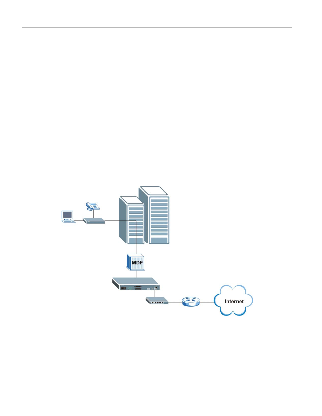
1.3.1 MTU Application
The following diagram depicts a typical application of the VES with Prestige 841 VDSL modems, in a large
residential building, or multiple tenant unit (MTU), that leverages existing phone line wiring to provide Internet
access to all tenants. Note that VDSL service can coexist with voice service on the same line.
Figure 1-1 MTU Application
1.3.2 Curbside Application
The VES can also be used by an Internet Service Provider (ISP) in a street cabinet to form a “mini POP (Point-ofPresence)” to provide broadband services to residential areas that are too far away from the ISP to avail of DSL
services. Residents need a VDSL modem, for example the Prestige 841, connected as shown in the previous figure.
1-4 Getting to know the VES-1124
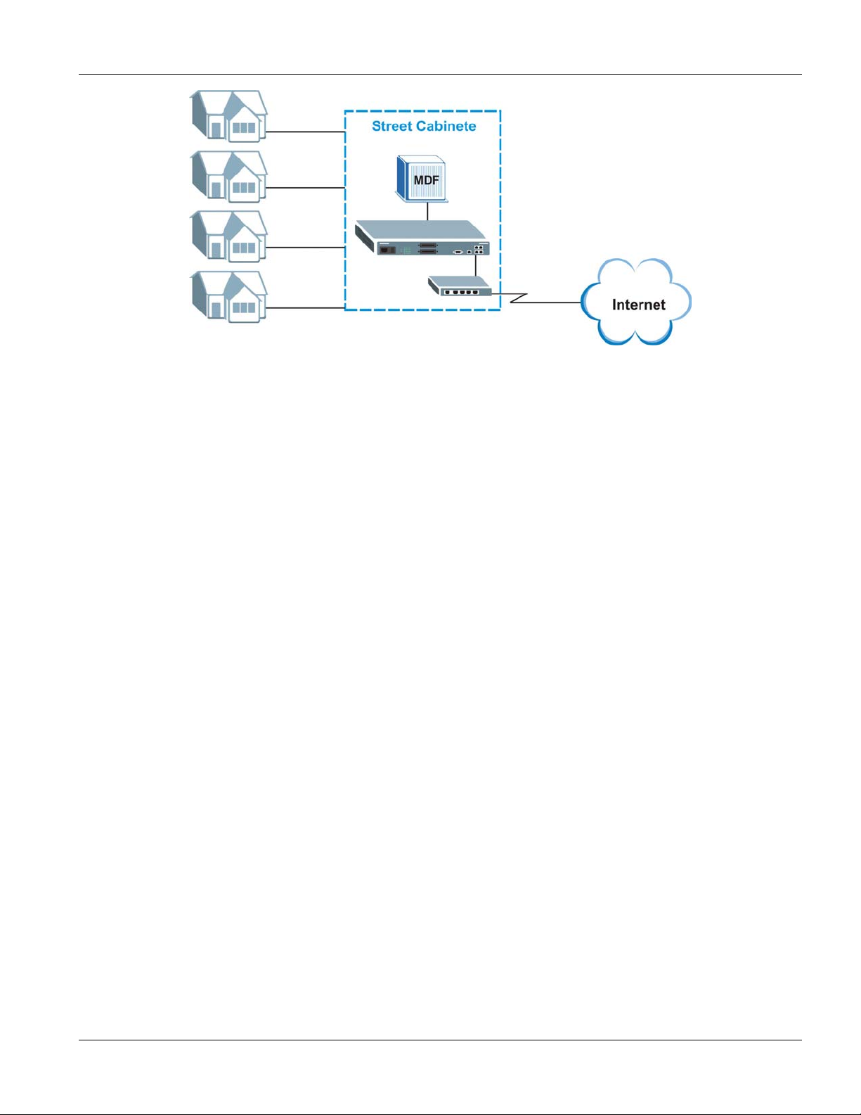
Figure 1-2 Curbside Application
VES-1124 User’s Guide
Getting to know the VES-1124 1-5

VES-1124 User’s Guide
Chapter 2
Hardware Installation
This chapter shows two switch installation scenarios.
2.1 Installation Scenarios
The switch can be placed on a desktop or rack-mounted on a standard EIA rack. Use the rubber feet in a desktop
installation and the brackets in a rack-mounted installation.
For proper ventilation, allow at least 4 inches (10 cm) of clearance at the front and 3.4 inches (8 cm) at the back of
the switch. This is especially important for enclosed rack installations.
2.2 Desktop Installation Procedure
1. Make sure the switch is clean and dry.
2. Set the switch on a smooth, level surface strong enough to support the weight of the switch and the
connected cables. Make sure there is a power outlet nearby.
3. Make sure there is enough clearance around the switch to allow air circulation and the attachment of cables
and the power cord.
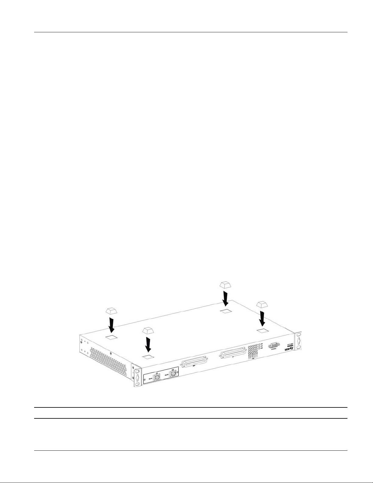
4. Remove the adhesive backing from the rubber feet.
5. Attach the rubber feet to each corner on the bottom of the switch. These rubber feet help protect the switch
from shock or vibration and ensure space between switches when stacking.
Figure 2-1 Attaching Rubber Feet
Do not block the ventilation holes. Leave space between switches when stacking.
Hardware Installation 2-1
VES-1124 User’s Guide
2.3 Rack-Mounted Installation
The switch can be mounted on an EIA standard size, 19-inch rack or in a wiring closet with other equipment.
Follow the steps below to mount your switch on a standard EIA rack using a rack-mounting kit.
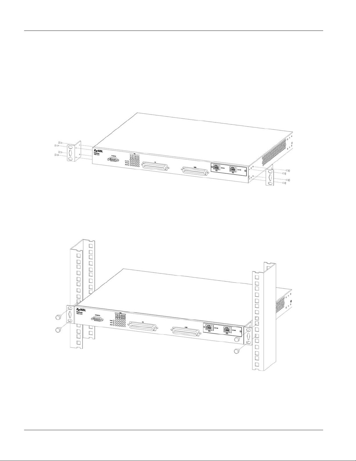
1. Align one bracket with the holes on one side of the switch and secure it with the bracket screws smaller
than the rack-mounting screws.
2. Attach the other bracket in a similar fashion.
Figure 2-2 Attaching Mounting Brackets and Screws
3. After attaching both mounting brackets, position the switch in the rack by lining up the holes in the
brackets with the appropriate holes on the rack. Secure the switch to the rack with the rack-mounting
screws.
Figure 2-3 Mounting the VES to an EIA standard 19-inch rack
2-2 Hardware Installation
VES-1124 User’s Guide
Chapter 3
Hardware Connections
This chapter acquaints you with the front and rear panels, shows you how to make the connections and
install/remove optional modules.
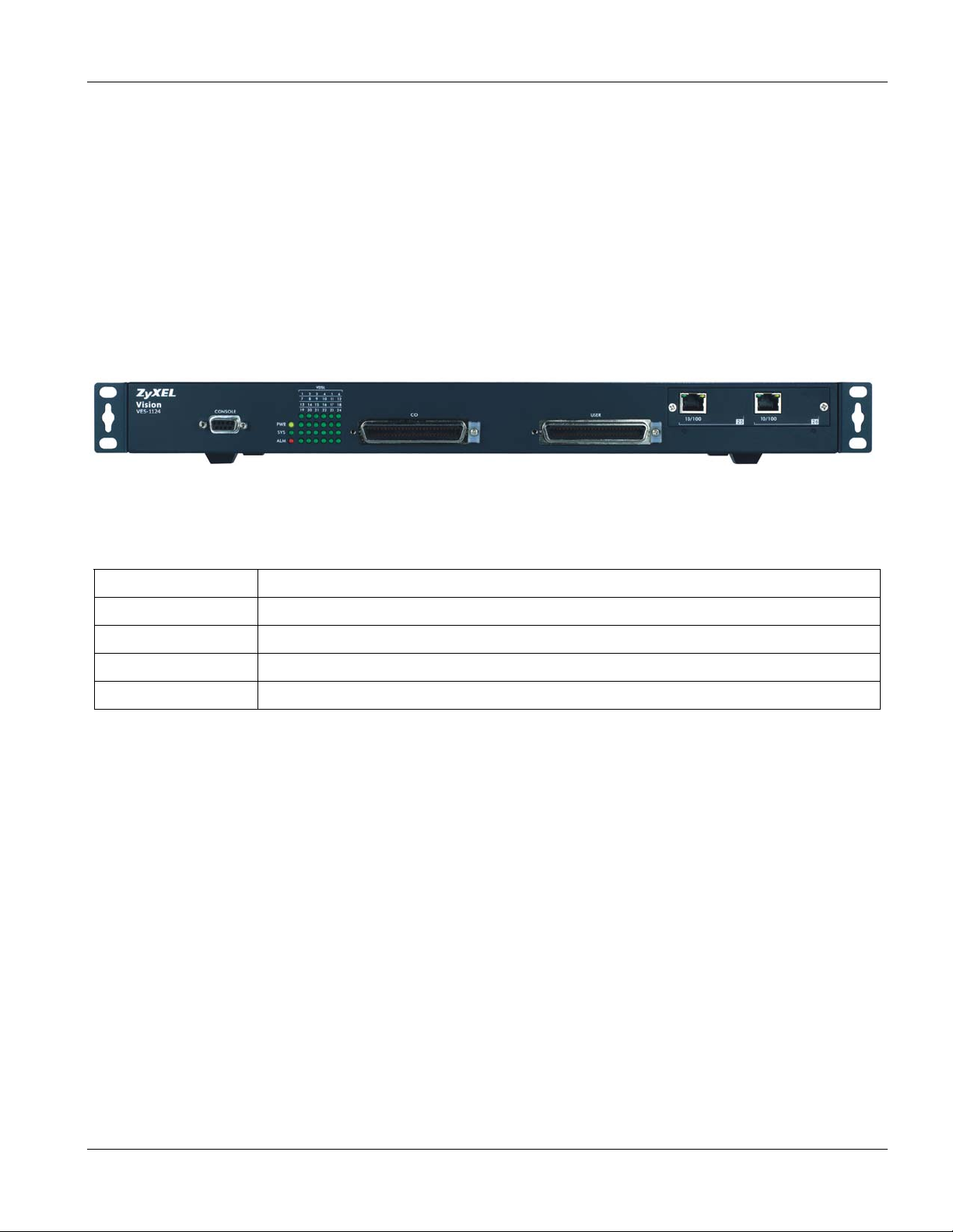
3.1 Front Panel
The following figure shows the front panel of the VES-1124. The front panel contains switch LEDs, two Telco-50
connectors and a console port for local switch management and two uplink ports.
Figure 3-1 VES-1124 Front Panel
The following table describes the ports on the front panel.
Table 3-1 VES-1124: Front Panel
CONNECTOR DESCRIPTION
CONSOLE The CONSOLE port is an RS-232 port for local configuration of the VES.
CO The CO Telco-50 port connects to the central office or a PBX.
USER The USER Telco-50 port connects to the user (subscriber) VDSL equipment.
10/100 (25, 26) These uplink ports allow you to connect to any switch.
3.1.1 Console Port Connection
For local management, you can use a computer with terminal emulation software configured to the following
parameters:
VT100 terminal emulation 9600 bps
No parity, 8 data bits, 1 stop bit No flow control
Connect the male 9-pin end of the console cable to the console port of the VES. Connect the female end to a serial
port (COM1, COM2 or other COM port) of your computer.
3.1.2 VDSL Port Connections
Connect the lines from the user equipment (VDSL modems) to the USER port and the lines from the central office
switch or PBX (Private Branch Exchange) to the
not shorted on the MDF (Main Distribution Frame).
Hardware Connections 3-1
CO port. Make sure that the USER line and the CO lines are

VES-1124 User’s Guide
The line from the user carries both the VDSL and the voice signals. For each line, the VES has a built-in splitter
that separates the high frequency VDSL signal from the voice band signal and feeds the VDSL signal to the VES,
while the voice band signal is diverted to the CO port.
3.1.3 10/100M Auto-Sensing Ethernet
The VES has 10/100Mbps auto-sensing Ethernet ports. There are two factors related to Ethernet: speed and duplex
mode. In 10/100Mbps Fast Ethernet, the speed can be 10Mbps or 100Mbps and the duplex mode can be half duplex
or full duplex. The auto-negotiation capability makes one Ethernet port able to negotiate with a peer automatically
to obtain the connection speed and duplex mode that both ends support.
When auto-negotiation is turned on, an Ethernet port on the VES negotiates with the peer automatically to
determine the connection speed and duplex mode. If the peer Ethernet port does not support auto-negotiation or
turns off this feature, the VES determines the connection speed by detecting the signal on the cable and using half
duplex mode. When the VES’s auto-negotiation is turned off, an Ethernet port uses the pre-configured speed and
duplex mode when making a connection, thus requiring you to make sure that the settings of the peer Ethernet port
are the same in order to connect.
You may also bundle the two Ethernet ports into one logical 200Mbps link.
Default Settings
The factory default settings for the Ethernet ports of the VES are:
Speed: Auto
Duplex: Auto
Flow control: Enable
Trunking: Disabled
Use a straight through Ethernet cable when connecting the VES to an Ethernet switch. Use a crossover Ethernet
cable if you are daisy-chaining multiple VESes and make sure trunking is disabled.
3.2 Front Panel LEDs
The following table describes the LED indicators on the front panel of the VES-1124.
Table 3-2 LED Descriptions
LED COLOR STATUS DESCRIPTION
On The system is turned on. PWR Green
Off The system is off.
SYS Green
ALM Red On There is a hardware failure.
3-2 Hardware Connections
Blinking The system is rebooting and performing self-diagnostic tests.
On The system is on and functioning properly.
Off The power is off or the system is not ready/malfunctioning.
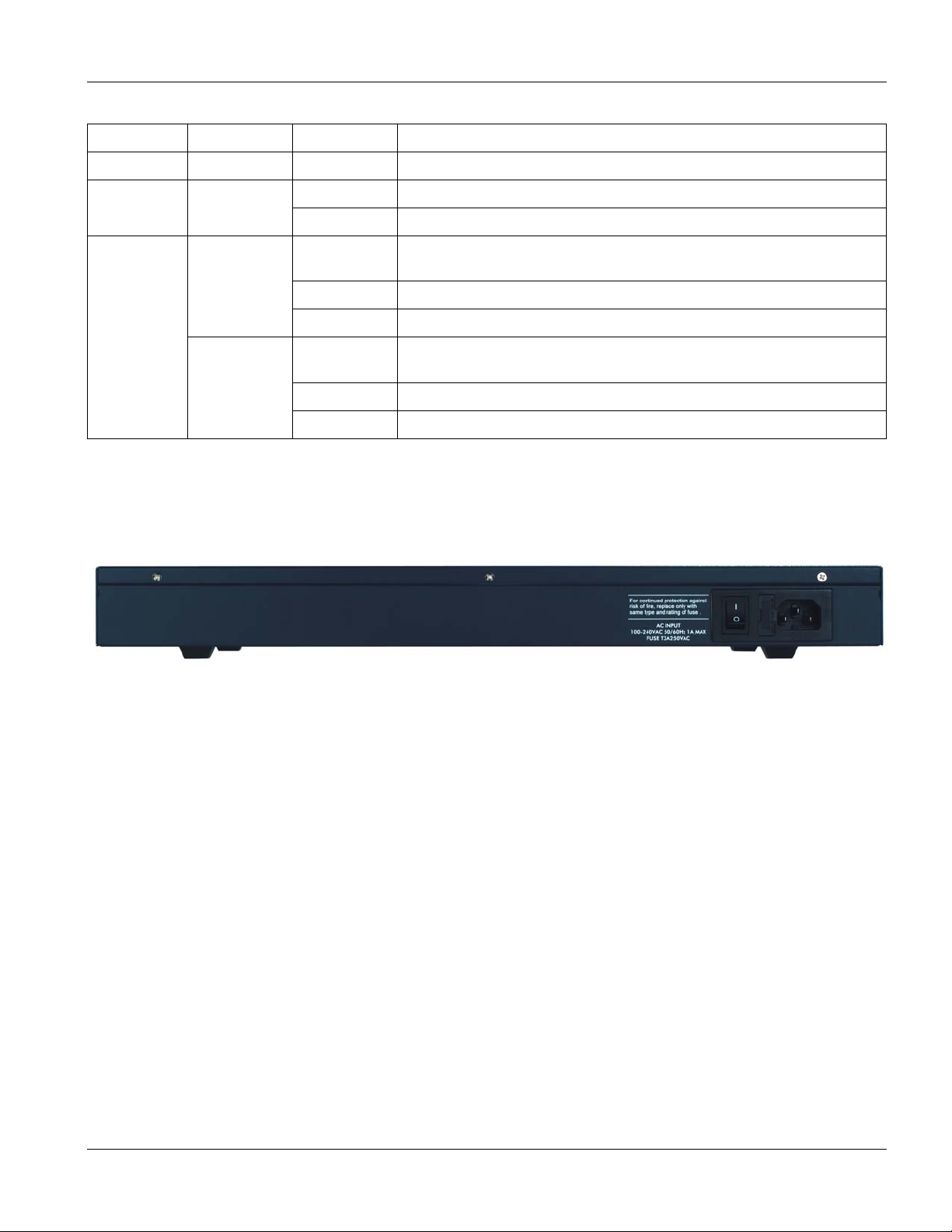
Table 3-2 LED Descriptions
LED COLOR STATUS DESCRIPTION
Off The system is functioning normally.
VES-1124 User’s Guide
On The link to the VDSL modem is up. VDSL
Off The link to the VDSL modem is down.
Blinking The system is transmitting/receiving to/from a 10 Mbps Ethernet
network.
On The link to a 10 Mbps Ethernet network is up.
Off The link to a 10 Mbps Ethernet network is down.
Blinking The system is transmitting/receiving to/from a 100 Mbps Ethernet
network.
On The link to a 100 Mbps Ethernet network is up.
Off The link to a 100 Mbps Ethernet network is down.
(1~24)
10/100
(25, 26)
Green
Green
Yellow
3.3 Rear Panel
The following figure shows the rear panel of the VES. The rear panel contains the power receptacle and the power
switch.
Figure 3-2 VES-1124 Back Panel
3.3.1 Power Connector
Make sure you are using the correct power source.
To connect the VES, plug the female end of the power cord to the power receptacle on the rear panel. Connect the
other end of the cord to a power outlet. Make sure that no objects obstruct the airflow of the fans (located on the
side of the unit).
Hardware Connections 3-3

 Loading...