

ZyXEL SLC1224 User Manual

SLC1224
SHDSL Line Card
User’s Guide
Version 3.50
11/2005
Edition 1


SLC1224 User’s Guide
Copyright
Copyright © 2005 by ZyXEL Communications Corporation.
The contents of this publication may not be reproduced in any part or as a whole, transcribed, stored in a
retrieval system, translated into any language, or transmitted in any form or by any means, electronic,
mechanical, magnetic, optical, chemical, photocopying, manual, or otherwise, without the prior written
permission of ZyXEL Communications Corporation.
Published by ZyXEL Communications Corporation. All rights reserved.
Disclaimer
ZyXEL does not assume any liability arising out of the application or use of any products, or software
described herein. Neither does it convey any license under its patent rights nor the patent rights of others.
ZyXEL further reserves the right to make changes in any products described herein without notice. This
publication is subject to change without notice.
Copyright 3

SLC1224 User’s Guide
Interference Statements and
Warnings
FCC Statement
This switch complies with Part 15 of the FCC rules. Operation is subject to the following two conditions:
1 This switch may not cause harmful interference.
2 This switch must accept any interference received, including interference that may cause undesired
operations.
FCC Warning
This equipment has been tested and found to comply with the limits for a Class A digital switch, pursuant
to Part 15 of the FCC Rules. These limits are designed to provide reasonable protection against harmful
interference in a commercial environment. This equipment generates, uses, and can radiate radio frequency
energy and, if not installed and used in accordance with the instruction manual, may cause harmful
interference to radio communications. Operation of this equipment in a residential area is likely to cause
harmful interference in which case the user will be required to correct the interference at his own expense.
CE Mark Warning:
This is a class A product. In a domestic environment this product may cause radio interference in which
case the user may be required to take adequate measures.
Taiwanese BSMI (Bureau of Standards, Metrology and Inspection) A Warning:
Certifications
1 Go to www.zyxel.com.
2 Select your product from the drop-down list box on the ZyXEL home page to go
to that product's page.
3 Select the certification you wish to view from this page.
Registration
Register your product online for free future product updates and information at
www.zyxel.com for global products, or at www.us.zyxel.com for North American
products.
4 Interference Statements and Warnings

SLC1224 User’s Guide
ZyXEL Limited Warranty
ZyXEL warrants to the original end user (purchaser) that this product is free from any defects in materials
or workmanship for a period of up to two years from the date of purchase. During the warranty period, and
upon proof of purchase, should the product have indications of failure due to faulty workmanship and/or
materials, ZyXEL will, at its discretion, repair or replace the defective products or components without
charge for either parts or labor, and to whatever extent it shall deem necessary to restore the product or
components to proper operating condition. Any replacement will consist of a new or re-manufactured
functionally equivalent product of equal value, and will be solely at the discretion of ZyXEL. This
warranty shall not apply if the product is modified, misused, tampered with, damaged by an act of God, or
subjected to abnormal working conditions.
Note
Repair or replacement, as provided under this warranty, is the exclusive remedy of the purchaser. This
warranty is in lieu of all other warranties, express or implied, including any implied warranty of
merchantability or fitness for a particular use or purpose. ZyXEL shall in no event be held liable for
indirect or consequential damages of any kind of character to the purchaser.
To obtain the services of this warranty, contact ZyXEL's Service Center for your Return Material
Authorization number (RMA). Products must be returned Postage Prepaid. It is recommended that the unit
be insured when shipped. Any returned products without proof of purchase or those with an out-dated
warranty will be repaired or replaced (at the discretion of ZyXEL) and the customer will be billed for parts
and labor. All repaired or replaced products will be shipped by ZyXEL to the corresponding return address,
Postage Paid. This warranty gives you specific legal rights, and you may also have other rights that vary
from country to country.
ZyXEL Limited Warranty 5

SLC1224 User’s Guide
Customer Support
Please have the following information ready when you contact customer support.
• Product model and serial number.
• Warranty Information.
• Date that you received your device.
• Brief description of the problem and the steps you took to solve it.
METHOD
LOCATION
CORPORATE
HEADQUARTERS
(WORLDWIDE)
CZECH REPUBLIC
DENMARK
FINLAND
FRANCE
GERMANY
HUNGARY
KAZAKHSTAN
NORTH AMERICA
NORWAY
SUPPORT E-MAIL TELEPHONE* WEB SITE
SALES E-MAIL FAX FTP SITE
support@zyxel.com.tw +886-3-578-3942 www.zyxel.com
www.europe.zyxel.com
sales@zyxel.com.tw +886-3-578-2439 ftp.zyxel.com
ftp.europe.zyxel.com
info@cz.zyxel.com +420-241-091-350 www.zyxel.cz ZyXEL Communications
info@cz.zyxel.com +420-241-091-359
support@zyxel.dk +45-39-55-07-00 www.zyxel.dk ZyXEL Communications A/S
sales@zyxel.dk +45-39-55-07-07
support@zyxel.fi +358-9-4780-8411 www.zyxel.fi ZyXEL Communications Oy
sales@zyxel.fi +358-9-4780 8448
info@zyxel.fr +33-4-72-52-97-97 www.zyxel.fr ZyXEL France
+33-4-72-52-19-20
support@zyxel.de +49-2405-6909-0 www.zyxel.de ZyXEL Deutschland GmbH.
sales@zyxel.de +49-2405-6909-99
support@zyxel.hu +36-1-3361649 www.zyxel.hu ZyXEL Hungary
info@zyxel.hu +36-1-3259100
http://zyxel.kz/support +7-3272-590-698 www.zyxel.kz ZyXEL Kazakhstan
sales@zyxel.kz +7-3272-590-689
support@zyxel.com 1-800-255-4101
+1-714-632-0882
sales@zyxel.com +1-714-632-0858 ftp.us.zyxel.com
support@zyxel.no +47-22-80-61-80 www.zyxel.no ZyXEL Communications A/S
sales@zyxel.no +47-22-80-61-81
www.us.zyxel.com ZyXEL Communications Inc.
REGULAR MAIL
ZyXEL Communications Corp.
6 Innovation Road II
Science Park
Hsinchu 300
Ta iw a n
Czech s.r.o.
Modranská 621
143 01 Praha 4 - Modrany
Ceská Republika
Columbusvej
2860 Soeborg
Denmark
Malminkaari 10
00700 Helsinki
Finland
1 rue des Vergers
Bat. 1 / C
69760 Limonest
France
Adenauerstr. 20/A2 D-52146
Wuerselen
Germany
48, Zoldlomb Str.
H-1025, Budapest
Hungary
43, Dostyk ave.,Office 414
Dostyk Business Centre
050010, Almaty
Republic of Kazakhstan
1130 N. Miller St.
Anaheim
CA 92806-2001
U.S.A.
Nils Hansens vei 13
0667 Oslo
Norway
6 Customer Support

SLC1224 User’s Guide
METHOD
LOCATION
POLAND
RUSSIA
SPAIN
SWEDEN
UKRAINE
UNITED KINGDOM
* “+” is the (prefix) number you enter to make an international telephone call.
SUPPORT E-MAIL TELEPHONE* WEB SITE
SALES E-MAIL FAX FTP SITE
info@pl.zyxel.com +48-22-5286603 www.pl.zyxel.com ZyXEL Communications
+48-22-5206701
http://zyxel.ru/support +7-095-542-89-29 www.zyxel.ru ZyXEL Russia
sales@zyxel.ru +7-095-542-89-25
support@zyxel.es +34-902-195-420 www.zyxel.es ZyXEL Communications
sales@zyxel.es +34-913-005-345
support@zyxel.se +46-31-744-7700 www.zyxel.se ZyXEL Communications A/S
sales@zyxel.se +46-31-744-7701
support@ua.zyxel.com +380-44-247-69-78 www.ua.zyxel.com ZyXEL Ukraine
sales@ua.zyxel.com +380-44-494-49-32
support@zyxel.co.uk +44-1344 303044
08707 555779 (UK only)
sales@zyxel.co.uk +44-1344 303034 ftp.zyxel.co.uk
REGULAR MAIL
ul.Emilli Plater 53
00-113 Warszawa
Poland
Ostrovityanova 37a Str.
Moscow, 117279
Russia
Alejandro Villegas 33
1º, 28043 Madrid
Spain
Sjöporten 4, 41764 Göteborg
Sweden
13, Pimonenko Str.
Kiev, 04050
Ukraine
www.zyxel.co.uk ZyXEL Communications UK
Ltd.,11 The Courtyard,
Eastern Road, Bracknell,
Berkshire, RG12 2XB,
United Kingdom (UK)
Customer Support 7

SLC1224 User’s Guide
8 Customer Support

SLC1224 User’s Guide
Table of Contents
Copyright ..................................................................................................................3
Interference Statements and Warnings.................................................................. 4
ZyXEL Limited Warranty.......................................................................................... 5
Customer Support.................................................................................................... 6
Preface ....................................................................................................................19
Chapter 1
SLC1224 Overview ................................................................................................. 21
1.1 SLC1224 Overview ............................................................................................21
1.2 Features .............................................................................................................21
1.3 Front Panels .......................................................................................................23
1.4 Ports and LEDs ..................................................................................................23
1.4.1 Ports .........................................................................................................23
1.4.2 LEDs .........................................................................................................23
1.5 Default Settings ..................................................................................................24
Chapter 2
Web Configurator Introduction............................................................................. 25
2.1 Web Configurator Overview ...............................................................................25
2.2 Accessing the Web Configurator ........................................................................25
2.2.1 Password ..................................................................................................25
2.3 Home Screen .....................................................................................................26
2.4 Screens Overview ..............................................................................................27
2.5 Saving Your Configuration ..................................................................................28
2.6 Navigating the Web Configurator .......................................................................28
2.7 Logging Out of the Web Configurator ...............................................................30
Chapter 3
G.SHDSL Port Setup ..............................................................................................31
3.1 G.SHDSL Standards Overview ...........................................................................31
3.2 Profiles ...............................................................................................................31
3.3 Configured Versus Actual Rate ..........................................................................32
3.4 Default Settings ..................................................................................................32
9

SLC1224 User’s Guide
3.5 N-wire Mode .......................................................................................................32
3.6 SLC Port Setup ..................................................................................................32
3.7 Virtual Channels .................................................................................................36
3.8 DSL Port Channel Setup ....................................................................................37
3.9 ATM QoS ............................................................................................................40
3.10 Traffic Shaping .................................................................................................40
3.11 VC Profile Setup ...............................................................................................43
3.12 G.SHDSL Profile Setup ....................................................................................45
3.13 IEEE 802.1X Authentication .............................................................................48
3.14 802.1X Setup ...................................................................................................48
3.15 Packet Type Filter ............................................................................................51
3.16 MAC Filter ........................................................................................................53
3.17 MAC Count Filter Setup ...................................................................................56
3.18 IGMP Filter Profile Setup .................................................................................58
3.6.1 SLC Port Edit ............................................................................................34
3.7.1 Super Channel ..........................................................................................36
3.7.2 LLC ...........................................................................................................37
3.7.3 VC Mux .....................................................................................................37
3.7.4 Virtual Channel Profile ..............................................................................37
3.8.1 Port Channel Add or Edit ..........................................................................38
3.10.1 ATM Traffic Classes ................................................................................40
3.10.1.1 Constant Bit Rate (CBR) ...............................................................40
3.10.1.2 Variable Bit Rate (VBR) .................................................................40
3.10.1.3 Unspecified Bit Rate (UBR) ...........................................................41
3.10.2 Traffic Parameters ..................................................................................41
3.10.2.1 Peak Cell Rate (PCR) ...................................................................41
3.10.2.2 Sustained Cell Rate (SCR) ............................................................41
3.10.2.3 Maximum Burst Size (MBS) ..........................................................41
3.10.2.4 Minimum Cell Rate (MCR) ............................................................41
3.10.2.5 Cell Delay Variation Tolerance (CDVT) .........................................42
3.10.2.6 Burst Tolerance (BT) .....................................................................42
3.10.2.7 Theoretical Arrival Time (TAT) .......................................................42
3.11.1 VC Profile Add or Edit .............................................................................44
3.12.1 G.SHDSL Profile Add or Edit ..................................................................46
3.14.1 Edit 802.1x Setup ...................................................................................50
3.15.1 Packet Type Filter Edit ............................................................................52
3.16.1 MAC Filter Entry List ...............................................................................54
3.16.1.1 MAC Filter Entry Add ....................................................................55
3.17.1 MAC Count Filter Edit .............................................................................57
3.18.1 IGMP Filter Profile Add or Edit ................................................................59
10

SLC1224 User’s Guide
Chapter 4
IEEE 802.1Q VLAN ................................................................................................. 63
4.1 IEEE 802.1Q VLAN Overview ............................................................................63
4.2 Static VLAN Setup ..............................................................................................63
4.2.1 Static VLAN Entry Add or Edit ..................................................................64
4.2.2 SLC Management VLAN Edit ...................................................................65
Chapter 5
Maintenance ........................................................................................................... 67
5.1 Firmware Upgrade ............................................................................................67
5.1.1 Procedure to upgrade your firmware: .......................................................67
Chapter 6
Statistics ................................................................................................................. 69
6.1 Statistics Overview .............................................................................................69
6.2 Statistics Screen .................................................................................................69
6.2.1 Hardware Monitor .....................................................................................70
6.2.2 Port Statistics ............................................................................................71
6.2.3 Channel Statistics .....................................................................................73
6.2.4 VLAN Status .............................................................................................74
Chapter 7
Diagnostic............................................................................................................... 77
7.1 Diagnostic Overview ..........................................................................................77
7.2 Diagnostic Screen ..............................................................................................77
7.3 Log Format .........................................................................................................78
7.4 Log Messages ....................................................................................................78
7.5 DSL Line Diagnostic ...........................................................................................80
Chapter 8
Commands Overview ............................................................................................ 83
8.1 Command Line Interface ...................................................................................83
8.1.1 Saving Your Configuration ........................................................................84
8.2 Command Shells ................................................................................................84
8.2.1 Changing Command Shells ......................................................................84
8.3 Standard Shell Commands with MSC ................................................................85
8.4 Engineer Shell Commands with MSC ................................................................89
Chapter 9
SHDSL Port Commands ........................................................................................ 95
9.1 SHDSL Overview ...............................................................................................95
9.2 Configured Versus Actual Rate ..........................................................................95
9.3 port Commands Summary .................................................................................95
11

SLC1224 User’s Guide
9.4 Port Command Examples ..................................................................................98
9.4.1 Port Show Command ................................................................................98
9.4.2 Port Disable Command .............................................................................99
9.4.3 Port Enable Command ...........................................................................100
9.4.4 Profile Show Command ..........................................................................100
9.4.5 SHDSL Profile Set Command .................................................................101
9.4.6 Profile Delete Command .........................................................................102
9.4.7 Virtual Channel Profile Set Command ....................................................103
9.4.8 PVC Set Command ................................................................................104
9.4.9 PVC Delete Command ...........................................................................105
9.4.10 Frame Type Set Command ...................................................................105
9.4.11 Packet Filter Set Command ..................................................................106
9.4.12 MAC Filter Show Command .................................................................107
9.4.13 MAC Filter Enable Command ...............................................................107
9.4.14 MAC Filter Disable Command ..............................................................108
9.4.15 MAC Filter Set Command .....................................................................108
9.4.16 MAC Filter Delete Command ................................................................109
9.4.17 MAC Count Show Command ................................................................109
9.4.18 MAC Count Enable Command .............................................................110
9.4.19 MAC Count Disable Command ............................................................. 111
9.4.20 MAC Count Set Command ................................................................... 111
9.4.21 Port Isolate Command .......................................................................... 112
9.4.22 Dot1x Show Command .........................................................................112
9.4.23 Dot1x Enable Command ....................................................................... 113
9.4.24 Dot1x Disable Command ......................................................................114
9.4.25 Dot1x Control Command ......................................................................114
9.4.26 Dot1x Re-authentication Command ...................................................... 115
9.4.27 Dot1x Period Command .......................................................................115
9.4.28 IGMP Filter Show Command ................................................................ 116
9.4.29 IGMP Filter Set Command .................................................................... 117
9.4.30 IGMP Filter Profile Set Command ........................................................118
9.4.31 IGMP Filter Profile Show Command ....................................................118
9.4.32 IGMP Filter Profile Delete Command ...................................................119
9.4.33 IGMP Filter Profile MAP Command ...................................................... 119
9.4.34 Lineinfo Command ................................................................................120
12
Chapter 10
Troubleshooting ................................................................................................... 121
10.1 The SYS or PWR LED Does Not Turn On .....................................................121
10.2 The ALM LED Is On .......................................................................................121
10.3 DSL Data Transmission .................................................................................122
10.4 Local Server ...................................................................................................122
10.5 Data Rate ......................................................................................................123

SLC1224 User’s Guide
10.6 Password .......................................................................................................123
10.7 The Line Card is not Manageable ..................................................................123
10.7.1 Uploading the Default Configuration File via Boot Commands .............123
10.7.2 Uploading the Firmware via Boot Commands ......................................124
Appendix A
Specifications....................................................................................................... 127
Index...................................................................................................................... 131
13

SLC1224 User’s Guide
14

SLC1224 User’s Guide
List of Figures
Figure 1 Front Panel ...........................................................................................................23
Figure 2 Login Screen ......................................................................................................... 26
Figure 3 Change Password Screen .................................................................................... 26
Figure 4 Home Screen ........................................................................................................ 27
Figure 5 Select a Line Card ................................................................................................ 28
Figure 6 SLC Port Setup Screen ......................................................................................... 29
Figure 7 SLC Edit Port Setup Screen ................................................................................. 30
Figure 8 Web Configurator: Logout Screen ....................................................................... 30
Figure 9 Port Setup ............................................................................................................. 32
Figure 10 SLC Port Setup ................................................................................................... 33
Figure 11 SLC Edit Port Setup ............................................................................................ 35
Figure 12 Port Channel Setup ............................................................................................. 38
Figure 13 Add Channel Setup ............................................................................................. 39
Figure 14 PCR, SCR, MCR and MBS in Traffic Shaping .................................................... 42
Figure 15 TAT, CDVT and BT in Traffic Shaping ................................................................. 42
Figure 16 VC Profile Setup ................................................................................................. 43
Figure 17 Add VC Profile .................................................................................................... 44
Figure 18 SLC GSHDSLProfile Setup ................................................................................. 46
Figure 19 Add GSHDSL Profile ........................................................................................... 47
Figure 20 802.1x Setup ....................................................................................................... 49
Figure 21 Edit 802.1x Setup ................................................................................................ 50
Figure 22 Packet Type Filter Setup ..................................................................................... 51
Figure 23 Packet Type Filter Edit ........................................................................................ 52
Figure 24 MAC Filter Setup ................................................................................................. 54
Figure 25 MAC Filter Entry List ........................................................................................... 55
Figure 26 MAC Filter Entry Add .......................................................................................... 55
Figure 27 MAC Count Filter Setup ...................................................................................... 57
Figure 28 MAC Count Filter Edit ......................................................................................... 58
Figure 29 IGMP Filter Profile Setup .................................................................................... 59
Figure 30 Add IGMP Filter Profile Setup ............................................................................. 60
Figure 31 VLAN Static Entry Setup ..................................................................................... 63
Figure 32 Add VLAN Static Entry ........................................................................................ 64
Figure 33 SLC Management VLAN Edit ............................................................................. 66
Figure 34 SLC Firmware Upgrade ...................................................................................... 68
Figure 35 SLC Statistics ...................................................................................................... 69
Figure 36 SLC Hardware Monitor ....................................................................................... 70
15

SLC1224 User’s Guide
Figure 37 SLC Port Statistics .............................................................................................. 72
Figure 38 SLC Channel Statistics ....................................................................................... 73
Figure 39 SLC 802.1Q VLAN Status ................................................................................... 75
Figure 40 Diagnostic ...........................................................................................................77
Figure 41 DSL Line Diagnostic ........................................................................................... 80
Figure 42 Changing to the Standard Shell Commands ....................................................... 84
Figure 43 Port Show Command Example ........................................................................... 99
Figure 44 Port Disable Command Example ........................................................................ 100
Figure 45 Port Enable Command Example ......................................................................... 100
Figure 46 Profile Show Command Example ....................................................................... 101
Figure 47 SHDSL Profile Set Command Example .............................................................. 102
Figure 48 SHDSL Profile Delete Command Example ......................................................... 103
Figure 49 Port PVC Set Command Example ...................................................................... 105
Figure 50 Frame Type Set Command Example .................................................................. 106
Figure 51 MAC Filter Show Command Example ................................................................ 107
Figure 52 MAC Filter Enable Command Example .............................................................. 108
Figure 53 MAC Filter Disable Command Example ............................................................. 108
Figure 54 MAC Filter Set Command Example .................................................................... 109
Figure 55 MAC Filter Delete Command Example ............................................................... 109
Figure 56 Mac Count Show Command Example ................................................................ 110
Figure 57 MAC Count Enable Command ............................................................................ 111
Figure 58 MAC Count Disable Command ........................................................................... 111
Figure 59 MAC Count Set Command ................................................................................. 112
Figure 60 Dot1x Show Command Example ........................................................................ 113
Figure 61 Dot1x Enable Command Example ...................................................................... 113
Figure 62 Dot1x Disable Command Example ..................................................................... 114
Figure 63 Dot1x Control Command Example ..................................................................... 115
Figure 64 Dot1x Re-authentication Command Example ..................................................... 115
Figure 65 Dot1x Period Command Example ....................................................................... 116
Figure 66 IGMP Filter Show Command Example ............................................................... 117
Figure 67 IGMP Filter Set Command Example ................................................................... 118
Figure 68 IGMP Filter Profile Set Command Example ........................................................ 118
Figure 69 IGMP Filter Profile Show Command Example .................................................... 119
Figure 70 IGMP Filter Profile Delete Command Example ................................................... 119
Figure 71 IGMP Filter Profile Map Command Example ...................................................... 120
Figure 72 Lineinfo Command Example ............................................................................... 120
Figure 73 Example Xmodem Upload .................................................................................. 124
Figure 74 Example Xmodem Upload .................................................................................. 125
Figure 75 SHDSL Telco-50 Pin Assignments ...................................................................... 128
Figure 76 Console Cable Mini RJ-11 Male Connector ........................................................ 130
16

SLC1224 User’s Guide
List of Tables
Table 1 Front Panel Ports ................................................................................................... 23
Table 2 LED Descriptions ................................................................................................... 23
Table 3 Default Settings ..................................................................................................... 24
Table 4 Web Configurator Screens .................................................................................... 27
Table 5 Select a Line Card ................................................................................................. 28
Table 6 Data Rates of the SLC’s SHDSL Ports .................................................................. 31
Table 7 SLC Port Setup ...................................................................................................... 33
Table 8 SLC Edit Port Setup .............................................................................................. 35
Table 9 Port Channel Setup ............................................................................................... 38
Table 10 Add Channel Setup ............................................................................................. 39
Table 11 VC Profile Setup .................................................................................................. 43
Table 12 Add VC Profile ..................................................................................................... 44
Table 13 SLC GSHDSL Profile Setup ................................................................................ 46
Table 14 Add GSHDSL Profile ........................................................................................... 47
Table 15 802.1x Setup ....................................................................................................... 49
Table 16 Edit 802.1x Setup ................................................................................................ 50
Table 17 Packet Type Filter Setup ..................................................................................... 52
Table 18 Packet Type Filter Edit ......................................................................................... 52
Table 19 MAC Filter Setup ................................................................................................. 54
Table 20 MAC Filter Entry List ............................................................................................ 55
Table 21 MAC Filter Entry Add ........................................................................................... 56
Table 22 MAC Count Filter Setup ....................................................................................... 57
Table 23 MAC Count Filter Edit .......................................................................................... 58
Table 24 IGMP Filter Profile Setup ..................................................................................... 59
Table 25 Add IGMP Filter Profile Setup ............................................................................. 60
Table 26 VLAN Static Entry Setup ...................................................................................... 63
Table 27 Add VLAN Static Entry ......................................................................................... 65
Table 28 SLC Management VLAN Edit .............................................................................. 66
Table 29 SLC Statistics ...................................................................................................... 69
Table 30 SLC Hardware Monitor ........................................................................................ 70
Table 31 SLC Port Statistics ............................................................................................... 72
Table 32 SLC Channel Statistics ........................................................................................ 74
Table 33 SLC 802.1Q VLAN Status ................................................................................... 75
Table 34 Diagnostic ............................................................................................................ 78
Table 35 Log Format .......................................................................................................... 78
Table 36 Log Messages ..................................................................................................... 78
17

SLC1224 User’s Guide
Table 37 DSL Line Diagnostic ............................................................................................ 81
Table 38 Standard Shell Commands .................................................................................. 85
Table 39 Engineer Shell Commands .................................................................................. 89
Table 40 Port Commands ................................................................................................... 95
Table 41 SYS LED Troubleshooting ................................................................................... 121
Table 42 ALM LED Troubleshooting ................................................................................... 121
Table 43 DSL Data Transmission Troubleshooting ............................................................ 122
Table 44 Local Server Troubleshooting .............................................................................. 122
Table 45 SYNC-rate Troubleshooting ................................................................................. 123
Table 46 Device Specifications ........................................................................................... 127
Table 47 SHDSL Telco-50 Connector Port and Pin Numbers ............................................ 129
Table 48 Wire Gauge Specifications .................................................................................. 129
Table 49 Console Cable Connector Pin Assignments ........................................................ 130
18

SLC1224 User’s Guide
Preface
Congratulations on your purchase of the SLC1224 SHDSL Line Card.
This preface discusses the conventions of this User’s Guide. It also provides information on
other related documentation.
Note: Register your product online to receive e-mail notices of firmware upgrades and
information at www.zyxel.com for global products, or at www.us.zyxel.com for
North American products.
About This User's Guide
This manual is designed to introduce you to the SLC1224 and give you detailed information
about the line card features and hardware.
Related Documentation
• IES-2000 or IES-3000 User’s Guide
Refer to the IES-2000 or IES-3000 User’s Guide for directions on installation,
connections, maintenance, hardware trouble shooting and safety warnings.
• MSC1000 Management Switch Card User’s Guide
This user’s guide provides hardware connection details and configuration and
management instructions for the management switch card.
• ZyXEL Glossary and Web Site
Please refer to www.zyxel.com for an online glossary of networking terms and additional
support documentation.
Syntax Conventions
• “Enter” means for you to type one or more characters. “Select” or “Choose” means for
you to use one of the predefined choices.
• Command and arrow keys are enclosed in square brackets.
carriage return key;
• Mouse action sequences are denoted using a comma. For example, “In Windows, click
Start, Settings and then Control Panel” means first click Start, then point your mouse
pointer to Settings and then click Control Panel.
• “e.g.,” is a shorthand for “for instance”, and “i.e.,” means “that is” or “in other words”.
• “IES-2000” or “IES-3000” refers to the IES-2000 or IES-3000 system including the main
and splitter chassis and their cards.
• “The MSC” refers to the MSC1000 management switch card.
• The SLC1224 SHDSL Line Card may be referred to as “the SLC1224”, “the SLC” or
“the line card” in this User’s Guide.
[ESC] means the Escape key and [SPACE BAR] means the Space Bar.
[ENTER] means the Enter, or
Preface 19

SLC1224 User’s Guide
User Guide Feedback
Help us help you. E-mail all User Guide-related comments, questions or suggestions for
improvement to techwriters@zyxel.com.tw or send regular mail to The Technical Writing
Team, ZyXEL Communications Corp., 6 Innovation Road II, Science-Based Industrial Park,
Hsinchu, 300, Taiwan. Thank you.
Firmware Naming Conventions
A firmware version includes the model code and release number as shown in the following
example.
Firmware Version: V3.50(ABH.0)
"ABH" is the model code.
"0" is this firmware's release number. This varies as new firmware is released. Your
firmware's release number may not match what is displayed in this User's Guide.
20 Preface

This chapter introduces the G.SHDSL line card's general features, factory default settings and
hardware.
1.1 SLC1224 Overview
The SLC1224 G.SHDSL Line Card is perfect for ISPs or large building applications seeking
to provide high bandwidth broadband services to subscribers while minimizing costs. It
connects up to 24 G.SHDSL subscribers.
G.SHDSL is an acronym for Single-pair High-speed Digital Subscriber Line. ITU-T G.991.2
defines the "G." in "G.SHDSL".
SLC1224 User’s Guide
CHAPTER 1
SLC1224 Overview
The SEC1024 (SHDSL Extension Card) sends the SHDSL traffic to the rear of the splitter
chassis.
Use this chapter's Telco-50 connector pin assignments along with the directions and safety
warnings in the IES-2000's or IES-3000’s User's Guide to install the cards and make the
necessary connections.
1.2 Features
G.SHDSL Compliance
• ITU-T G.991.2
• ITU-T G.991.2 bis
• ITU-T G.994.1
• Rate adaptation support
IEEE 802.1p Priority
Your SLC uses IEEE 802.1p priority to assign priority levels to individual ports and prioritize
traffic based on those levels.
System Monitoring
• System status (link status, rates, statistics counters)
• Temperatures, voltage reports and alarms.
Chapter 1 SLC1224 Overview 21

SLC1224 User’s Guide
Alarm LED
An ALM (alarm) LED lights when the SLC is overheated or the voltage readings are outside
the tolerance levels and turns off when the temperature or voltage has returned to a normal
level. Fans in the main chassis cool the unit.
N-wire Mode
The n-wire mode allows you to physically bundle two or four G.SHDSL ports into a single 4wire or 8-wire G.SHDSL connection. This can increase the reach of G.SHDSL or give
increased bandwidth when connecting to 4-wire mode G.SHDSL modems or another SLC.
IEEE 802.1Q Tagged VLAN
Your SLC uses the IEEE 802.1Q Tagged VLAN (Virtual Local Area Network), which allows
it to deliver tagged/untagged frames to and from its ports. The SLC supports up to 4094
individual VLANs.
IEEE 802.1x Port-based Authentication
The SLC supports the IEEE 802.1x standard for centralized user authentication and
accounting management through an optional network authentication (RADIUS) server.
MAC (Media Access Control) Count Filter
You can limit the number of MAC addresses that may be dynamically learned on a port. You
may enable/disable the MAC count filter on individual ports.
System Error Logging
The SLC's system error log will record error logs locally. These logs may be viewed again
after a warm restart.
IGMP Snooping
With IGMP snooping, group multicast traffic is only forwarded to ports that are members of
that group. IGMP snooping generates no additional network traffic, allowing you to
significantly reduce multicast traffic passing through your SLC.
Multiple PVC
The SLC allows you to use different channels (also called Permanent Virtual Circuits or
PVCs) for different services or subscribers. You can define up to four channels on each DSL
port and use them for different services or levels of service. You set the default port VID that
is assigned to untagged frames received on each channel. You also set an IEEE 802.1p priority
for each PVC. In this way you can assign different priorities to different channels (and
consequently the services that get carried on them or the subscribers that use them).
22 Chapter 1 SLC1224 Overview
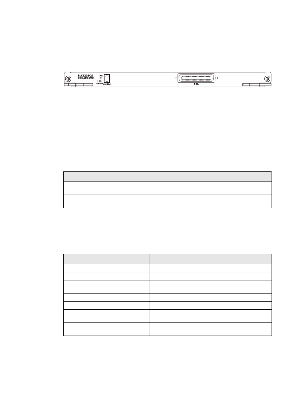
1.3 Front Panels
The figure below shows the front panel of the SLC.
Figure 1 Front Panel
1.4 Ports and LEDs
These are the details of the SLC1224 ports and LEDs.
1.4.1 Ports
The following table describes the port labels on the front panel.
Table 1 Front Panel Ports
SLC1224 User’s Guide
LABEL DESCRIPTION
CONSOLE For troubleshooting purposes, this mini RJ-11 port connects to a computer when
SHDSL The Telco-50 connector is for connecting to the SEC1024 (SHDSL Extension
1.4.2 LEDs
The following table describes the LED indicators on the front panel of the SLC.
Table 2 LED Descriptions
LED COLOR STATUS DESCRIPTION
PWR Green. On The line card is turned on.
SYS Green Blinking The line card is rebooting and performing self-diagnostic
ALM Red On The line card has overheated or its voltage is out of the
the line card is not manageable from the MSC.
Card).
Off The line card is off or not receiving power.
tests.
On The line card is on and functioning properly.
Off The power is off or the line card is not ready/malfunctioning.
normal range.
Off The line card is functioning within normal temperature and
voltage range.
Chapter 1 SLC1224 Overview 23
SLC1224 User’s Guide
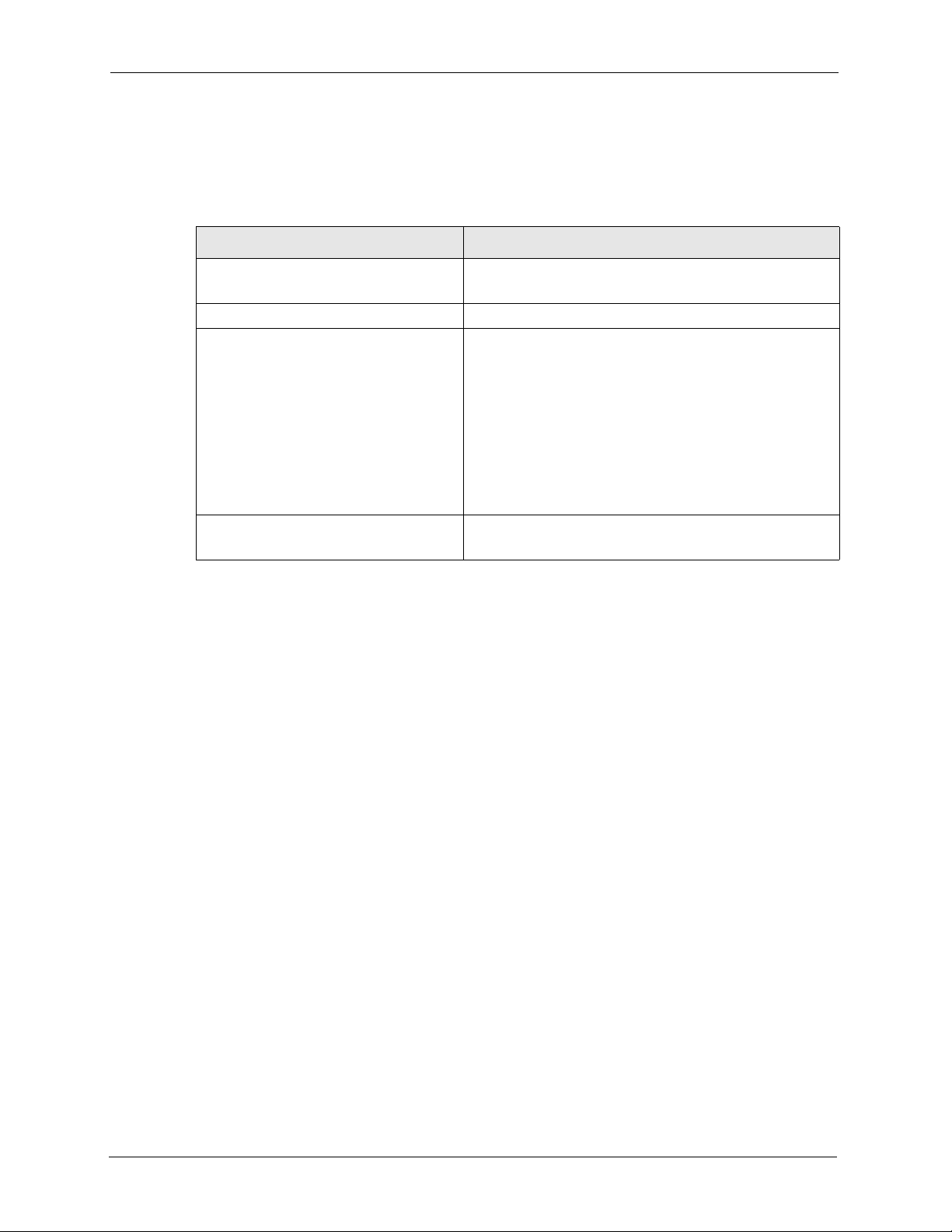
1.5 Default Settings
These are the line card's factory default settings.
Table 3 Default Settings
ITEM DEFAULT VALUES
SNMP Community Settings Read = public
Telnet and FTP Password 1234 (default)
G.SHDSL Ports Encapsulation: RFC 1483
Other Factory Defaults Secured Host: Disabled
Write = public
ATM Traffic Class: UBR
Multiplexing: LLC-based
VPI: 0
VCI: 33
Enable/Disable State: Disabled
Profile: DEFVAL
• Maximum upstream/downstream speed: 2304 Kbps
• Minimum upstream/downstream speed: 192 Kbps
Sys Error Log: Always Enabled
24 Chapter 1 SLC1224 Overview

CHAPTER 2
Web Configurator Introduction
This chapter tells how to access and navigate the web configurator when you use the line card
with the management switch card.
2.1 Web Configurator Overview
The web configurator allows you to use a web browser to manage the G.SHDSL line card
while it is behind the management switch card. The chapters on using the web configurator
with the management switch card give basic descriptions of the G.SHDSL line card screens.
2.2 Accessing the Web Configurator
SLC1224 User’s Guide
The web configurator is an HTML-based management interface that allows easy SLC setup
and management via Internet browser. Use Internet Explorer 6.0 and later versions. The
recommended screen resolution is 1024 by 768 pixels.
In order to use the web configurator you need to allow:
• Web browser pop-up windows from your device. Web pop-up blocking is enabled by
default in Windows XP SP (Service Pack) 2.
• JavaScripts (enabled by default).
• Java permissions (enabled by default).
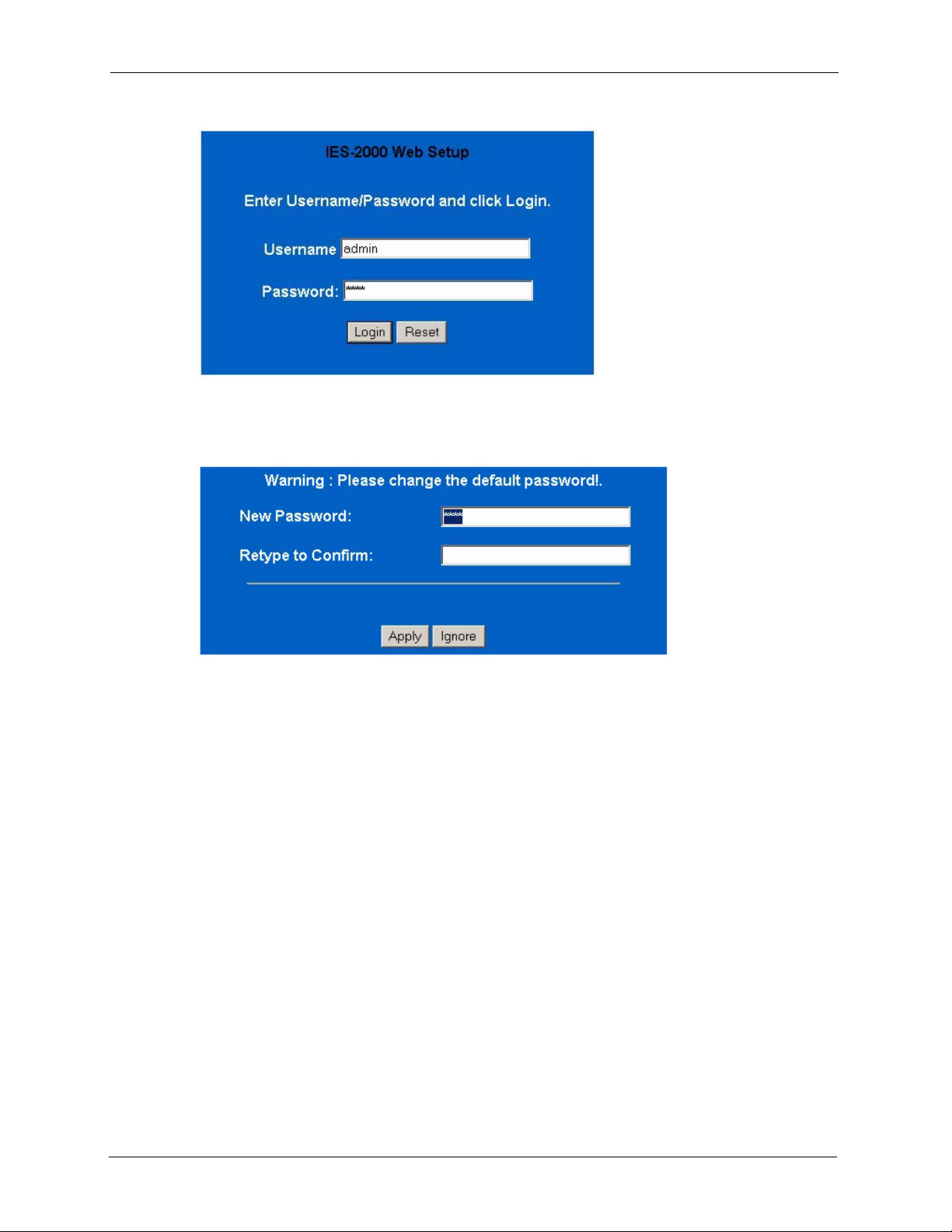
2.2.1 Password
1 Launch your web browser and enter the IP address of the SLC ("192.168.1.1" is the
factory default) in the Location or Address field. Press Enter.
2 The Password screen now appears. Type “admin” in the user name field (it may display
automatically for you) and your password (factory default “1234”) in the password field.
Click Login.
Chapter 2 Web Configurator Introduction 25
SLC1224 User’s Guide
Figure 2 Login Screen
3 This screen prompts you to change your password if it is still set to the default. Type a
new password (and retype it to confirm) and click Apply or click Ignore.
Figure 3 Change Password Screen
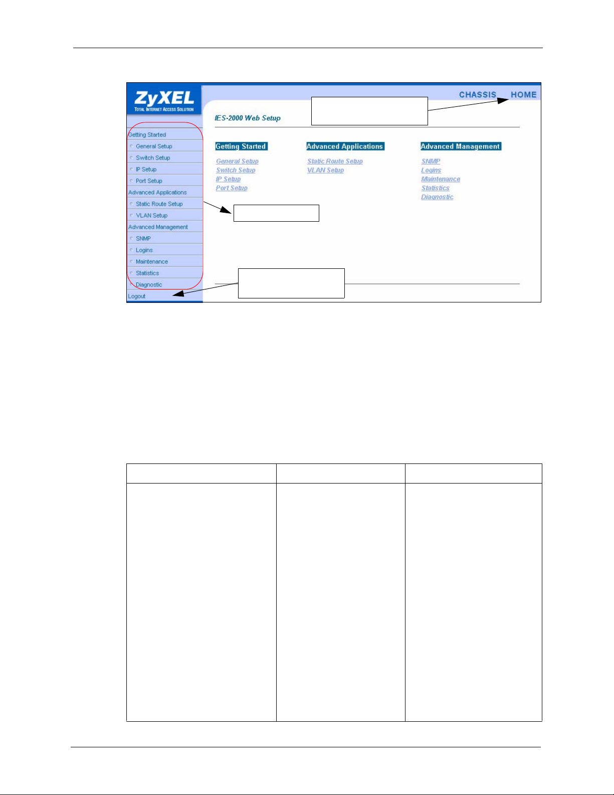
2.3 Home Screen
This is the web configurator's Home screen.
26 Chapter 2 Web Configurator Introduction
SLC1224 User’s Guide
Figure 4 Home Screen
Click Home to view current
device statistics.
Navigation Panel
Click Logout to exit the
web configurator.
In the navigation panel, click a main link to reveal a list of submenu links. Click a submenu
link to go to the corresponding screen.
2.4 Screens Overview
The following table lists the various web configurator screens that pertain to the SHDSL line
card.
Table 4 Web Configurator Screens
GETTING STARTED ADVANCED APPLICATIONS ADVANCED MANAGEMENT
Port Setup
SLC Port Setup
SLC Profile Setup
SLC Profile Add/Edit
802.1x Setup
Edit 802.1x Setup
Packet Type Filter Setup
Packet Type Filter Edit
MAC Filter Setup
MAC Filter Entry List
MAC Filter Entry Add
MAC Count Filter Setup
MAC Count Filter Edit
SLC Edit Port Setup
Channel Setup
VC Profile Setup
Edit VC Profile Setup
Edit Channel Setup
VLAN Setup
SLC Static VLAN Setup
Add/Edit Static VLAN
Maintenance
Firmware Upgrade
SLC Firmware Upgrade
Statistics
SLC Statistics
SLC Hardware Monitor
SLC Port Statistics
SLC Channel Statistics
SLC VLAN Status
Diagnostic
SLC Diagnostic
SLC Diagnostic DSL
Chapter 2 Web Configurator Introduction 27
SLC1224 User’s Guide
2.5 Saving Your Configuration
Click Apply in a configuration screen when you are done modifying the settings in that screen
to save your changes back to the switch.
2.6 Navigating the Web Configurator
The web configurator uses multiple levels. You only need to use one level for features that
deal with the IES-2000 or IES-3000 as a whole. For example, to configure General Setup,
click the link on the navigation panel to open the configuration screen.
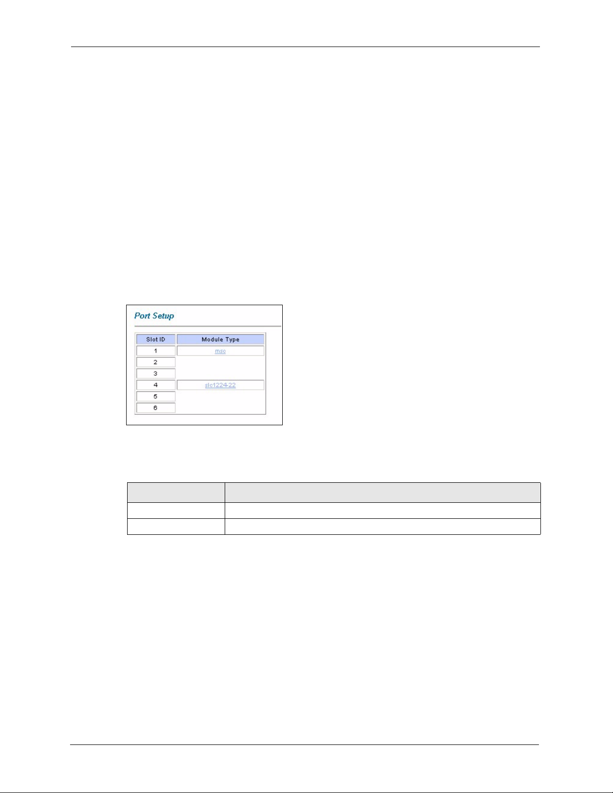
Features that are based on individual cards, for example Port Setup, require you to go down
another level. Click the link on the navigation panel, and then click the card’s link (see Figure
5 on page 28) to open the configuration screen.
Figure 5 Select a Line Card
The following table describes the labels in this screen.
Table 5 Select a Line Card
LABEL DESCRIPTION
Slot ID This is the slot number.
Module Type Click a link in this column to go to the port setup screens for a card.
There may be yet more levels below to allow you to make more and more specific
configurations, for example Port Setup on the G.SHDSL line card has screens that allow you
to configure individual profiles and individual ports.
Configuration screens for individual cards display the card’s slot number in front of the
screens title in the upper left hand corner of the screen (see Figure 6 on page 29).
Many of the configuration screens that are based on individual cards have one or more links in
the upper-right corner. Click a link to go to the screen with the same name. For example, click
Port Setup in the SLC Port Setup screen (see Figure 6 on page 29) to go to the general Port
Setup screen (see Figure 5 on page 28).
28 Chapter 2 Web Configurator Introduction

Figure 6 SLC Port Setup Screen
SLC1224 User’s Guide
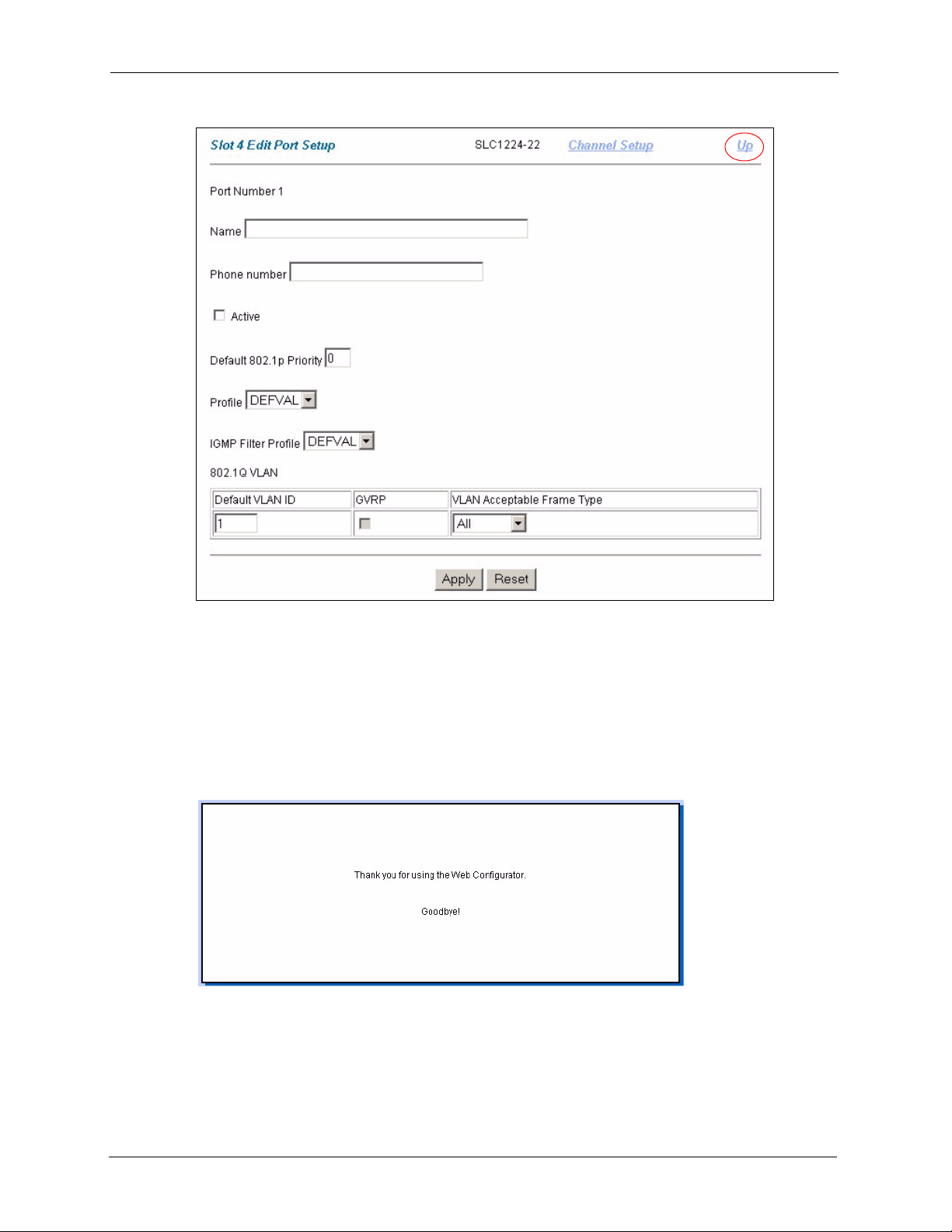
Click a link labeled Up to go to a screen on the next higher level. For example, click Up in the
SLC Edit Port Setup screen (see Figure 7 on page 30) to go to the SLC Port Setup screen
(see Figure 6 on page 29).
Chapter 2 Web Configurator Introduction 29
SLC1224 User’s Guide
Figure 7 SLC Edit Port Setup Screen
2.7 Logging Out of the Web Configurator
Click Logout in a screen to exit the web configurator. You have to log in with your password
again after you log out. This is recommended after you finish a management session both for
security reasons and so you don’t lock out other SLC administrators.
Figure 8 Web Configurator: Logout Screen
30 Chapter 2 Web Configurator Introduction
 Loading...