

ZyXEL SHD1112 User Manual
1
SHD1112
MOTION DETECTOR
The Motion Detector is a Z-WaveTM enabled device and is fully compatible with any
Z-WaveTM enabled network. Z-WaveTM enabled devices displaying the Z-WaveTM
logo can also be used with it regardless of the manufacturer, and ours can also be
used in other manufacturer’s Z-WaveTM enabled networks. This Motion Detector is
controllable to our modules, such as On/Off Module SHD2110 and Lamp Module
SHD2210. Inclusion of this Motion Detector on other manufacturer’s Wireless
Controller menu allows remote turn-on of connected modules and their connected
lighting when the Detector is triggered. Z-WaveTM nodes in the system also act as
repeaters if they support that function.
The Motion Detector is designed to detect movement in a protected area by
detecting changes in infra-red radiation levels caused, for example, when a person
moves within or across the devices field of vision, a trigger radio signal will be
transmitted.
Adding to Z-WaveTM Network
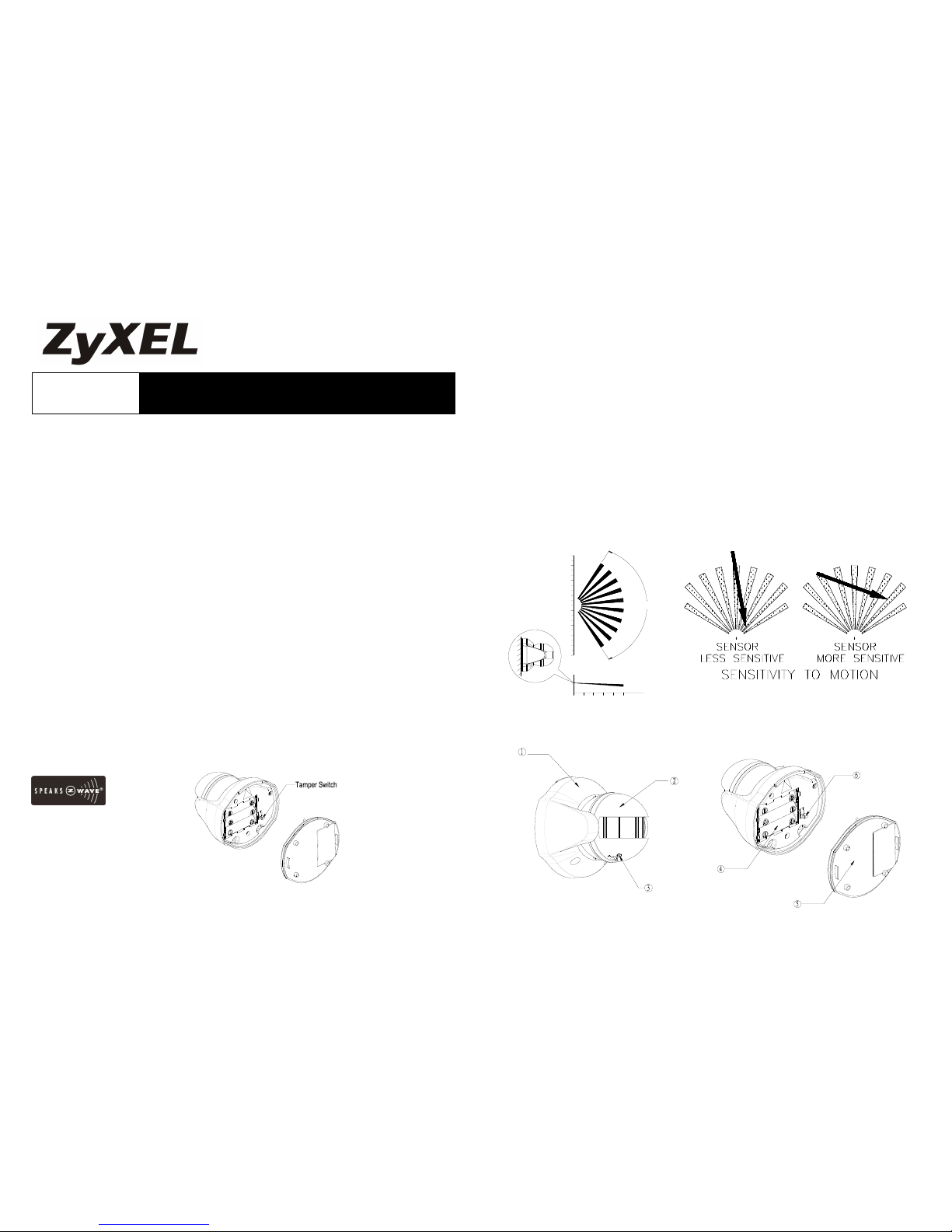
In the rear casing, there is a tamper switch which is used to carry out inclusion,
exclusion or association. Put a Z-WaveTM Wireless Controller into
inclusion/exclusion mode, press the tamper switch on the detector to complete the
inclusion/exclusion process. The Motion Detector supports one association group
with five nodes. This has the effect that when the Detector trigger, all devices
associated with Detector will be operated.
The Motion Detector will stay “awake” for ten minutes when changing the status of
tamper switch from being pressed to be released or from being released to be
pressed to allow time for configuration. (FIGURE 1)
FIGURE 1
Choosing A Mounting Location
The recommended position for a Motion Detector is in the corner of a room
mounted 2m from the floor. At this height, the detector will detect movement
up to 6-12m depending on adjustment. (FIGURE 2a) Also, in this position, the
100 degrees fan-shaped detection pattern can normally offer greater protection
than mounting on a flat wall. Before selecting a position for a Motion Detector
the following points should be noted:
1. Do not position the detector facing a window or direct sunlight. Motion
Detectors are not suitable for use in conservatories or draughty areas.
2. Do not position the detector directly above or facing any source of heat, eg: fires,
radiators, boiler etc.
3. Where possible, mount the detector so that the logical path of an intruder would
cut across the fan pattern rather than directly towards the detector.(FIGURE
2b)
FIGURE 2a FIGURE 2b
Installation
60 2
2.0
2
0
10
6
(M)
10
(M)
100°
4 8
4
8
2
4
6
8
10
2
Front Cover
Battery
Motion Sensor
Rear Cover
Time-off Knob
Tamper Switch
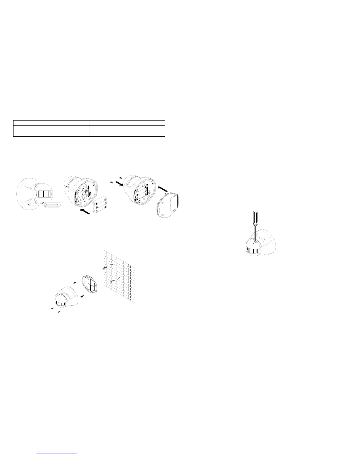
1. Use a Phillips screwdriver to detach the rear cover. (FIGURE 3a)
2. Insert 3 AA-size 1.5V batteries to the battery compartment, ensuring that
correct polarity is put. (FIGURE 3b)
Note: The adoption of alkaline battery is highly recommended, as it would last
for longer period.
3. Refit the rear cover. (FIGURE 3c)
FIGURE 3a FIGURE 3b FIGURE 3c
4. Hold the rear cover in position and mark the two mounting holes. Drill the holes,
insert the plastic wall plugs and screw the rear cover to the wall using the
screws supplied. Offer the Detector up to the rear cover using screws as
originally supplied. (FIGURE 4)
FIGURE 4
Note: After removing batteries, wait for 5 seconds to refit batteries.
Operation
1. With the tamper switch not being pressed, the unit enters test mode, which
allows the user to make a test. When the movement has been detected, the
red indicator LED on the Detector will illuminate and the load or the lamp
plugged into the On/Off Module SHD2110, Lamp Module SHD2210 will turn ON.
It implies that the unit is working properly.
Note: When the battery is connected, the LED behind the lens will be on for
about 1 minute as warming-up duration until the Motion Sensor has stabilized
when the LED turns OFF.
Time-off knob controls how long the connected load or lamp will stay on after
the motion has been detected. It is set from 5 seconds to 12 minutes. “T”
means 5 seconds, while “+” is 12 minutes. After the expiry of preset time-off, the
Detector will turn OFF the load or the lamp plugged into the On/Off Module
SHD2110, Lamp Module SHD2210. The red indicator LED on the load or the
connected lamp will be off too.
2. When the tamper switch is pressed, the unit will enter normal mode. Upon
motion being sensed, the Detector will turn ON the load or the lamp plugged
into the On/Off Module SHD2110, Lamp Module SHD2210.
After the elapse of preset time-off, the Detector will turn OFF the load or the
lamp plugged into the On/Off Module SHD2110, Lamp Module SHD2210.
In normal mode with the tamper switch being pressed, the red indicator LED on
the Detector will not illuminate to conserve battery life when the detector is
triggered, (unless the battery is low).
3. By pressing the tamper switch for more than 5 seconds, and then release it.
The Detector will send an alarm command (ALARM_REPORT, Alarm Type ==
 Loading...