

Page 1

Quick Start Guide
SBG3500-N Series
SBG3500-N000 / SBG3500-NB00
Wireless N Fiber WAN Small Business Gateway
Version 1.00
Edition 4, 9/2014
User’s Guide
Default Login Details
LAN IP Address http://192.168.1.1
User Name admin
Password 1234
www.zyxel.com
Copyright © 2014 ZyXEL Communications Corporation
Page 2

IMPORTANT!
READ CAREFULLY BEFORE USE.
KEEP THIS GUIDE FOR FUTURE REFERENCE.
Screenshots and graphics in this book may differ slightly from your product due to differences in
your product firmware or your computer operating system. Every effort has been made to ensure
that the information in this manual is accurate.
Related Documentation
•Quick Start Guide
The Quick Start Guide shows how to connect the SBG3500-N Series and access the Web
Configurator wizards. It contains information on setting up your network and configuring for
Internet access.
SBG3500-N Series User’s Guide
2
Page 3

Contents Overview
Contents Overview
User’s Guide .......................................................................................................................................16
Introducing the SBG3500-N Series .........................................................................................................17
The Web Configurator .............................................................................................................................25
Quick Start ...............................................................................................................................................32
Tutorials ..................................................................................................................................................35
Technical Reference ..........................................................................................................................96
Status Screens ........................................................................................................................................97
Broadband .............................................................................................................................................100
Wireless ................................................................................................................................................130
LAN .......................................................................................................................................................159
Routing ..................................................................................................................................................179
Quality of Service (QoS) .......................................................................................................................185
Network Address Translation (NAT) ......................................................................................................203
Dynamic DNS Setup .............................................................................................................................219
AP Control .............................................................................................................................................222
AP Profile ..............................................................................................................................................227
Interface Group .....................................................................................................................................243
USB Service ..........................................................................................................................................248
Firewall ..................................................................................................................................................251
MAC Filter .............................................................................................................................................261
User Access Control .............................................................................................................................264
Scheduler Rules ....................................................................................................................................267
Certificates ............................................................................................................................................269
IPSec VPN ............................................................................................................................................275
PPTP VPN ............................................................................................................................................294
L2TP VPN .............................................................................................................................................299
Log .......................................................................................................................................................305
Network Status .....................................................................................................................................308
ARP Table ............................................................................................................................................. 311
Routing Table ........................................................................................................................................313
IGMP Status .........................................................................................................................................315
xDSL Statistics ......................................................................................................................................316
AP Monitor ............................................................................................................................................319
MyZyXEL ...............................................................................................................................................323
User Account .........................................................................................................................................325
Remote Management ............................................................................................................................328
TR-069 Client ........................................................................................................................................330
SBG3500-N Series User’s Guide
3
Page 4

Contents Overview
SNMP ....................................................................................................................................................332
Time ......................................................................................................................................................334
E-mail Notification .................................................................................................................................337
Logs Setting .........................................................................................................................................339
Firmware Upgrade ................................................................................................................................342
Configuration .........................................................................................................................................344
Diagnostic .............................................................................................................................................347
Troubleshooting ....................................................................................................................................352
SBG3500-N Series User’s Guide
4
Page 5

Table of Contents
Table of Contents
Contents Overview ..............................................................................................................................3
Table of Contents .................................................................................................................................5
Part I: User’s Guide .........................................................................................16
Chapter 1
Introducing the SBG3500-N Series...................................................................................................17
1.1 Overview ...........................................................................................................................................17
1.2 Applications for the SBG3500-N Series ...........................................................................................17
1.2.1 Internet Access ........................................................................................................................17
1.2.2 Wireless LAN ...........................................................................................................................20
1.2.3 SBG3500-N Series’s USB Support ..........................................................................................21
1.3 LEDs (Lights) ....................................................................................................................................21
1.4 Ways to Manage the SBG3500-N Series ..........................................................................................24
1.5 Good Habits for Managing the SBG3500-N Series ...........................................................................24
1.6 The RESET Button ............................................................................................................................24
Chapter 2
The Web Configurator........................................................................................................................25
2.1 Overview ...........................................................................................................................................25
2.1.1 Accessing the Web Configurator .............................................................................................25
2.2 Web Configurator Layout ..................................................................................................................27
2.2.1 Title Bar ...................................................................................................................................27
2.2.2 Main Window ...........................................................................................................................28
2.2.3 Navigation Panel .....................................................................................................................28
Chapter 3
Quick Start...........................................................................................................................................32
3.1 Overview ...........................................................................................................................................32
3.2 Quick Start Setup ..............................................................................................................................32
Chapter 4
Tutorials...............................................................................................................................................35
4.1 Overview ...........................................................................................................................................35
4.2 Setting Up an ADSL PPPoE Connection ..........................................................................................35
4.3 Setting Up a GbE WAN connection ..................................................................................................38
4.4 Setting Up a 3G WAN connection .....................................................................................................40
SBG3500-N Series User’s Guide
5
Page 6

Table of Contents
4.5 Setting Up a Secure Wireless Network .............................................................................................40
4.5.1 Configuring the Wireless Network Settings .............................................................................41
4.5.2 Using WPS ..............................................................................................................................43
4.5.3 Without WPS ...........................................................................................................................47
4.6 Setting Up Multiple Wireless Groups ................................................................................................48
4.7 Configuring Static Route for Routing to Another Network .................................................................51
4.8 Configuring QoS Queue and Class Setup ........................................................................................54
4.9 Access the SBG3500-N Series Using DDNS ....................................................................................57
4.9.1 Registering a DDNS Account on www.dyndns.org ..................................................................57
4.9.2 Configuring DDNS on Your SBG3500-N Series ......................................................................58
4.9.3 Testing the DDNS Setting ........................................................................................................58
4.10 Configuring the MAC Address Filter ................................................................................................58
4.11 Access Your Shared Files From a Computer ..................................................................................60
4.12 Certificate Configuration for VPN ....................................................................................................61
4.13 Examples of Configuring IPSec VPN Rules ....................................................................................64
4.13.1 Example 1: Use 3DES Encryption .........................................................................................64
4.13.2 Example 2: Use AES128 Encryption .....................................................................................67
4.13.3 Example 3: Configuring a Site-to-Site with Dynamic Peer Rule ............................................68
4.13.4 Example 4: Configuring a Remote Access Rule ....................................................................68
4.14 PPTP VPN Tutorial .........................................................................................................................69
4.14.1 Configuring PPTP VPN Setup (Server) .................................................................................69
4.14.2 Configuring PPTP VPN on Windows (Client) ........................................................................70
4.14.3 Configuring PPTP VPN on Android Devices (Client) .............................................................77
4.14.4 Configuring PPTP VPN in iOS Devices (Client) ....................................................................79
4.15 L2TP VPN Tutorial ..........................................................................................................................81
4.15.1 Configuring the Default_L2TPVPN IPSec VPN Rule (Server) ..............................................81
4.15.2 Configuring the L2TP VPN Setup (Server) ............................................................................82
4.15.3 Configuring L2TP VPN in Windows (Client) ..........................................................................83
4.15.4 Configuring L2TP VPN on Windows 7 ...................................................................................84
4.15.5 Configuring L2TP VPN on Android Devices (Client) .............................................................91
4.15.6 Configuring L2TP VPN in iOS Devices (Client) .....................................................................93
Part II: Technical Reference............................................................................96
Chapter 5
Status Screens....................................................................................................................................97
5.1 Overview ...........................................................................................................................................97
5.2 The Status Screen .............................................................................................................................97
Chapter 6
Broadband.........................................................................................................................................100
SBG3500-N Series User’s Guide
6
Page 7

Table of Contents
6.1 Overview .........................................................................................................................................100
6.1.1 What You Can Do in this Chapter ..........................................................................................100
6.1.2 What You Need to Know ........................................................................................................101
6.1.3 Before You Begin ...................................................................................................................104
6.2 The Broadband Screen ...................................................................................................................104
6.2.1 Add/Edit Internet Connection .................................................................................................106
6.3 The 3G WAN Screen ...................................................................................................................... 114
6.4 The Add New 3G Dongle Screen .................................................................................................... 118
6.4.1 Add 3G Dongle Information ...................................................................................................118
6.5 The Advanced Screen ..................................................................................................................... 119
6.6 The 802.1x Screen ..........................................................................................................................120
6.6.1 Edit 802.1x Settings ...............................................................................................................121
6.7 The multi-WAN Screen ...................................................................................................................122
6.7.1 Add/Edit multi-WAN ...............................................................................................................122
6.7.2 How to Configure multi-WAN for Load-Balancing and Fail-Over ...........................................123
6.8 Technical Reference ........................................................................................................................125
Chapter 7
Wireless.............................................................................................................................................130
7.1 Overview .........................................................................................................................................130
7.1.1 What You Can Do in this Chapter ..........................................................................................130
7.1.2 What You Need to Know ........................................................................................................131
7.2 The General Screen .......................................................................................................................131
7.2.1 No Security ............................................................................................................................134
7.2.2 Basic (WEP Encryption) ........................................................................................................134
7.2.3 More Secure (WPA(2)-PSK) ..................................................................................................136
7.2.4 WPA(2) Authentication ...........................................................................................................137
7.3 The More AP Screen .......................................................................................................................138
7.3.1 Edit More AP ........................................................................................................................139
7.4 MAC Authentication ........................................................................................................................141
7.5 The WPS Screen ............................................................................................................................142
7.6 The WMM Screen ...........................................................................................................................143
7.7 The Others Screen ..........................................................................................................................144
7.8 The Channel Status Screen ............................................................................................................146
7.9 Technical Reference ........................................................................................................................146
7.9.1 Wireless Network Overview ...................................................................................................146
7.9.2 Additional Wireless Terms .....................................................................................................148
7.9.3 Wireless Security Overview ...................................................................................................148
7.9.4 Signal Problems ....................................................................................................................150
7.9.5 BSS .......................................................................................................................................151
7.9.6 MBSSID .................................................................................................................................151
7.9.7 Preamble Type ......................................................................................................................152
7.9.8 WiFi Protected Setup (WPS) .................................................................................................152
SBG3500-N Series User’s Guide
7
Page 8

Table of Contents
Chapter 8
LAN .................................................................................................................................................... 159
8.1 Overview .........................................................................................................................................159
8.1.1 What You Can Do in this Chapter ..........................................................................................159
8.1.2 What You Need To Know .......................................................................................................160
8.1.3 Before You Begin ...................................................................................................................161
8.2 The LAN Setup Screen ...................................................................................................................161
8.3 The Static DHCP Screen .................................................................................................................165
8.4 The UPnP Screen ...........................................................................................................................167
8.5 Installing UPnP in Windows Example .............................................................................................167
8.5.1 Using UPnP in Windows XP Example ...................................................................................169
8.5.2 Web Configurator Easy Access .............................................................................................171
8.6 The Additional Subnet Screen ........................................................................................................174
8.7 The 5th Ethernet Port Screen .........................................................................................................175
8.8 Technical Reference ........................................................................................................................175
8.8.1 LANs, WANs and the SBG3500-N Series .............................................................................175
8.8.2 DHCP Setup ..........................................................................................................................176
8.8.3 DNS Server Addresses .........................................................................................................176
8.8.4 LAN TCP/IP ...........................................................................................................................177
Chapter 9
Routing ..............................................................................................................................................179
9.1 Overview ........................................................................................................................................179
9.1.1 What You Can Do in this Chapter ..........................................................................................179
9.2 The Routing Screen ........................................................................................................................180
9.2.1 Add/Edit Static Route .............................................................................................................180
9.3 The Policy Forwarding Screen ........................................................................................................181
9.3.1 Add/Edit Policy Forwarding ...................................................................................................182
9.4 The RIP Screen ...............................................................................................................................183
Chapter 10
Quality of Service (QoS)...................................................................................................................185
10.1 Overview ......................................................................................................................................185
10.1.1 What You Can Do in this Chapter ........................................................................................185
10.2 What You Need to Know ...............................................................................................................186
10.3 The Quality of Service General Screen ........................................................................................187
10.4 The Queue Setup Screen .............................................................................................................188
10.4.1 Adding a QoS Queue .........................................................................................................190
10.5 The Class Setup Screen ...............................................................................................................190
10.5.1 Add/Edit QoS Class ............................................................................................................191
10.6 The QoS Policer Setup Screen .....................................................................................................195
10.6.1 Add/Edit a QoS Policer .......................................................................................................196
10.7 The QoS Monitor Screen .............................................................................................................197
SBG3500-N Series User’s Guide
8
Page 9

Table of Contents
10.8 Technical Reference ......................................................................................................................198
Chapter 11
Network Address Translation (NAT)................................................................................................203
11.1 Overview .......................................................................................................................................203
11.1.1 What You Can Do in this Chapter ........................................................................................203
11.1.2 What You Need To Know .....................................................................................................203
11.2 The Port Forwarding Screen ........................................................................................................204
11.2.1 Add/Edit Port Forwarding ....................................................................................................206
11.3 The Applications Screen ...............................................................................................................207
11.3.1 Add New Application ............................................................................................................208
11.4 The Port Triggering Screen ...........................................................................................................208
11.4.1 Add/Edit Port Triggering Rule .............................................................................................210
11.5 The Default Server Screen ............................................................................................................ 211
11.6 The ALG Screen ............................................................................................................................212
11.7 The Address Mapping Screen .......................................................................................................212
11.7.1 Add/Edit Address Mapping Rule ..........................................................................................213
11.8 Technical Reference ......................................................................................................................214
11.8.1 NAT Definitions ....................................................................................................................214
11.8.2 What NAT Does ...................................................................................................................215
11.8.3 How NAT Works ...................................................................................................................216
11.8.4 NAT Application ...................................................................................................................216
Chapter 12
Dynamic DNS Setup .........................................................................................................................219
12.1 Overview .......................................................................................................................................219
12.1.1 What You Can Do in this Chapter ........................................................................................219
12.1.2 What You Need To Know .....................................................................................................220
12.2 The DNS Entry Screen ..................................................................................................................220
12.2.1 Add/Edit DNS Entry .............................................................................................................220
12.3 The Dynamic DNS Screen ............................................................................................................221
Chapter 13
AP Control.........................................................................................................................................222
13.1 Overview .......................................................................................................................................222
13.1.1 What You Can Do in this Chapter ........................................................................................222
13.2 The Controller Screen ...................................................................................................................222
13.3 The Managed AP List Screen .......................................................................................................223
13.4 The Load Balancing Screen ..........................................................................................................224
13.5 The Dynamic Channel Selection Screen ......................................................................................225
Chapter 14
AP Profile...........................................................................................................................................227
SBG3500-N Series User’s Guide
9
Page 10

Table of Contents
14.1 Overview .......................................................................................................................................227
14.1.1 What You Can Do in this Chapter ........................................................................................227
14.1.2 What You Need To Know .....................................................................................................227
14.2 Radio Screen ...............................................................................................................................228
14.2.1 Add/Modify New Profile .......................................................................................................229
14.3 SSID Screen ................................................................................................................................233
14.3.1 Add New Profile/Modify SSID Profile ...................................................................................234
14.4 Security Screen .............................................................................................................................235
14.4.1 Add/Modify Security Profile .................................................................................................236
14.5 MAC Filtering Screen ....................................................................................................................239
14.5.1 Add New Entry/Modify MAC Filtering Profile .......................................................................240
14.6 Layer-2 Isolation Overview ............................................................................................................240
14.7 Layer-2 Isolation Screen ..............................................................................................................241
14.7.1 Add New Profile/Modify Layer-2 Isolation ...........................................................................242
Chapter 15
Interface Group.................................................................................................................................243
15.1 Overview .......................................................................................................................................243
15.2 The Interface Group/VLAN Screen ...............................................................................................243
15.2.1 Interface Group Configuration .............................................................................................244
15.2.2 Interface Grouping Criteria .................................................................................................245
Chapter 16
USB Service ......................................................................................................................................248
16.1 Overview .......................................................................................................................................248
16.1.1 What You Can Do in this Chapter ........................................................................................248
16.1.2 What You Need To Know .....................................................................................................248
16.2 The File Sharing Screen ...............................................................................................................249
16.2.1 Before You Begin .................................................................................................................249
Chapter 17
Firewall .............................................................................................................................................. 251
17.1 Overview .......................................................................................................................................251
17.1.1 What You Can Do in this Chapter ........................................................................................251
17.1.2 What You Need to Know ......................................................................................................252
17.2 The Firewall Screen ......................................................................................................................253
17.3 The DoS Screen ............................................................................................................................253
17.4 The Service Screen ......................................................................................................................254
17.4.1 Add/Edit a Service ..............................................................................................................255
17.5 The Access Control Screen ..........................................................................................................257
17.5.1 Add/Edit an ACL Rule ........................................................................................................258
17.6 The Zone Control Screen ..............................................................................................................260
SBG3500-N Series User’s Guide
10
Page 11

Table of Contents
Chapter 18
MAC Filter..........................................................................................................................................261
18.1 Overview ......................................................................................................................................261
18.2 The MAC Filter Screen ..................................................................................................................262
Chapter 19
User Access Control ........................................................................................................................264
19.1 Overview .......................................................................................................................................264
19.2 The User Access Control Screen ..................................................................................................264
19.2.1 Add/Edit a User Access Control Rule ..................................................................................265
Chapter 20
Scheduler Rules................................................................................................................................267
20.1 Overview .......................................................................................................................................267
20.2 The Scheduler Rules Screen ........................................................................................................267
20.2.1 Add/Edit a Schedule ............................................................................................................267
Chapter 21
Certificates........................................................................................................................................269
21.1 Overview .......................................................................................................................................269
21.1.1 What You Can Do in this Chapter ........................................................................................269
21.2 What You Need to Know ...............................................................................................................269
21.3 The Local Certificates Screen .......................................................................................................269
21.3.1 Create Certificate Request .................................................................................................270
21.3.2 Load Signed Certificate ......................................................................................................272
21.4 The Trusted CA Screen ................................................................................................................273
21.4.1 Import Trusted CA Certificate ..............................................................................................273
Chapter 22
IPSec VPN..........................................................................................................................................275
22.1 Overview .......................................................................................................................................275
22.2 What You Can Do in this Chapter .................................................................................................275
22.3 What You Need To Know ..............................................................................................................276
22.4 The Setup Screen .........................................................................................................................276
22.4.1 Add/Edit VPN Rule ..............................................................................................................277
22.4.2 The VPN Connection Add/Edit Screen ................................................................................277
22.4.3 The Default_L2TPVPN IPSec VPN Rule .............................................................................285
22.5 The IPSec VPN Monitor Screen ....................................................................................................285
22.6 The Radius Screen .......................................................................................................................286
22.7 Technical Reference ......................................................................................................................287
22.7.1 IPSec Architecture ...............................................................................................................287
22.7.2 Encapsulation ......................................................................................................................288
22.7.3 IKE Phases .........................................................................................................................289
SBG3500-N Series User’s Guide
11
Page 12

Table of Contents
22.7.4 Negotiation Mode ................................................................................................................290
22.7.5 IPSec and NAT ....................................................................................................................290
22.7.6 VPN, NAT, and NAT Traversal .............................................................................................291
22.7.7 ID Type and Content ............................................................................................................292
22.7.8 Pre-Shared Key ...................................................................................................................293
22.7.9 Diffie-Hellman (DH) Key Groups ..........................................................................................293
Chapter 23
PPTP VPN..........................................................................................................................................294
23.1 Overview .......................................................................................................................................294
23.2 What You Can Do in this Chapter .................................................................................................294
23.3 PPTP VPN Setup ..........................................................................................................................295
23.4 The PPTP VPN Monitor Screen ....................................................................................................296
23.5 PPTP VPN Troubleshooting Tips ..................................................................................................296
Chapter 24
L2TP VPN...........................................................................................................................................299
24.1 Overview .......................................................................................................................................299
24.1.1 What You Can Do in this Chapter ........................................................................................299
24.2 L2TP VPN Screen .........................................................................................................................299
24.3 The L2TP VPN Monitor Screen .....................................................................................................301
24.4 L2TP VPN Troubleshooting Tips ...................................................................................................301
Chapter 25
Log ....................................................................................................................................................305
25.1 Overview .......................................................................................................................................305
25.1.1 What You Can Do in this Chapter ........................................................................................305
25.1.2 What You Need To Know .....................................................................................................305
25.2 The System Log Screen ................................................................................................................306
25.3 The Security Log Screen ...............................................................................................................306
Chapter 26
Network Status .................................................................................................................................308
26.1 Overview .......................................................................................................................................308
26.1.1 What You Can Do in this Chapter ........................................................................................308
26.2 The WAN Status Screen ...............................................................................................................308
26.3 The LAN Status Screen .................................................................................................................309
26.4 The DHCP Client Screen ..............................................................................................................309
Chapter 27
ARP Table..........................................................................................................................................311
27.1 Overview ....................................................................................................................................... 311
27.1.1 How ARP Works .................................................................................................................. 311
SBG3500-N Series User’s Guide
12
Page 13

Table of Contents
27.2 ARP Table Screen .........................................................................................................................311
Chapter 28
Routing Table....................................................................................................................................313
28.1 Overview .......................................................................................................................................313
28.2 The Routing Table Screen .............................................................................................................313
Chapter 29
IGMP Status ......................................................................................................................................315
29.1 Overview .......................................................................................................................................315
29.2 The IGMP Group Status Screen ...................................................................................................315
Chapter 30
xDSL Statistics..................................................................................................................................316
30.1 The xDSL Statistics Screen ...........................................................................................................316
Chapter 31
AP Monitor.........................................................................................................................................319
31.1 Overview .......................................................................................................................................319
31.1.1 What You Can Do in this Chapter ........................................................................................319
31.2 AP List Screen .............................................................................................................................319
31.3 Radio List Screen ..........................................................................................................................320
31.4 Station List Screen .......................................................................................................................321
Chapter 32
MyZyXEL............................................................................................................................................323
32.1 MyZyXEL Overview .......................................................................................................................323
32.2 The License Status Screen ...........................................................................................................323
Chapter 33
User Account ....................................................................................................................................325
33.1 Overview ......................................................................................................................................325
33.2 The User Account Screen .............................................................................................................325
33.2.1 Add/Edit a User Account ....................................................................................................326
Chapter 34
Remote Management........................................................................................................................328
34.1 Overview .......................................................................................................................................328
34.2 The Remote MGMT Screen ..........................................................................................................328
Chapter 35
TR-069 Client.....................................................................................................................................330
35.1 Overview .......................................................................................................................................330
SBG3500-N Series User’s Guide
13
Page 14

Table of Contents
35.2 The TR-069 Client Screen ............................................................................................................330
Chapter 36
SNMP .................................................................................................................................................332
36.1 The SNMP Agent Screen ..............................................................................................................332
Chapter 37
Time ...................................................................................................................................................334
37.1 Overview .......................................................................................................................................334
37.2 The Time Screen ..........................................................................................................................334
Chapter 38
E-mail Notification............................................................................................................................337
38.1 Overview ....................................................................................................................................337
38.2 The Email Notification Screen .......................................................................................................337
38.2.1 Email Notification Edit ........................................................................................................337
Chapter 39
Logs Setting ..................................................................................................................................... 339
39.1 Overview ......................................................................................................................................339
39.2 The Log Setting Screen ................................................................................................................339
39.2.1 Example E-mail Log ............................................................................................................340
Chapter 40
Firmware Upgrade ............................................................................................................................342
40.1 Overview .......................................................................................................................................342
40.2 The Firmware Screen ....................................................................................................................342
Chapter 41
Configuration ....................................................................................................................................344
41.1 Overview .......................................................................................................................................344
41.2 The Configuration Screen .............................................................................................................344
41.3 The Reboot Screen .......................................................................................................................346
Chapter 42
Diagnostic .........................................................................................................................................347
42.1 Overview .......................................................................................................................................347
42.1.1 What You Can Do in this Chapter ........................................................................................347
42.2 What You Need to Know ...............................................................................................................347
42.3 Ping & TraceRoute & NsLookup ...................................................................................................348
42.4 802.1ag .........................................................................................................................................348
42.5 OAM Ping Test ..............................................................................................................................349
SBG3500-N Series User’s Guide
14
Page 15

Table of Contents
Chapter 43
Troubleshooting................................................................................................................................352
43.1 Power, Hardware Connections, and LEDs ....................................................................................352
43.2 SBG3500-N Series Access and Login ..........................................................................................353
43.3 Internet Access .............................................................................................................................355
43.4 Wireless Internet Access ...............................................................................................................356
43.5 USB Device Connection ................................................................................................................357
43.6 UPnP .............................................................................................................................................358
Appendix A Setting up Your Computer’s IP Address.......................................................................359
Appendix B IP Addresses and Subnetting.......................................................................................379
Appendix C Pop-up Windows, JavaScript and Java Permissions...................................................387
Appendix D Wireless LANs..............................................................................................................394
Appendix E IPv6 ..............................................................................................................................407
Appendix F Services........................................................................................................................415
Appendix G Legal Information .........................................................................................................419
Appendix H Customer Support........................................................................................................424
Index ..................................................................................................................................................430
SBG3500-N Series User’s Guide
15
Page 16

PART I
User’s Guide
16
Page 17

1.1 Overview
The SBG3500-N Series is a secure VPN (Virtual Private Network), multi-WAN gateway that provides
high-speed Internet access for business users. It features not only VDSL2/ADSL2+ Bonding
functionality, but also one Gigabit Ethernet (GbE) WAN with Small Form Factor Pluggable (SFP)
interface. SFP is also known as Fiber Optics interface. The GbE WAN with SFP is a dual-personality
design (GbE + Fiber) which enables increased bandwidth and extended coverage. Namely, the
SBG3500-N Series can adopt varied network environment and enable service providers to flexibly
install this device for VDSL, Fiber and 3G, in addition to provide load-balancing to ensure seamless
Internet connectivity.
FEATURES
• Four GbE Ports for LAN Connection
• One USB Port for 3G Connection and File Sharing
• One SFP Port for Fiber Optic Internet Connection
•One GbE WAN Port
• Two VDSL2/ADSL2+ (SBG3500-N000 only) Integrated Ports (Bonding)
• One VDSL2/ADSL2+ (SBG3500-NB00 only) Port
• Integrated Firewall with Secure Network Management
• IP secure VPN
CHAPTER 1
Introducing the SBG3500-N Series
Only use firmware for your SBG3500-N Series’s specific model. Refer to
the label on the bottom of your SBG3500-N Series.
Note: SFP and GbE connections cannot be used at the same time.
1.2 Applications for the SBG3500-N Series
Here are some example uses for which the SBG3500-N Series is well suited.
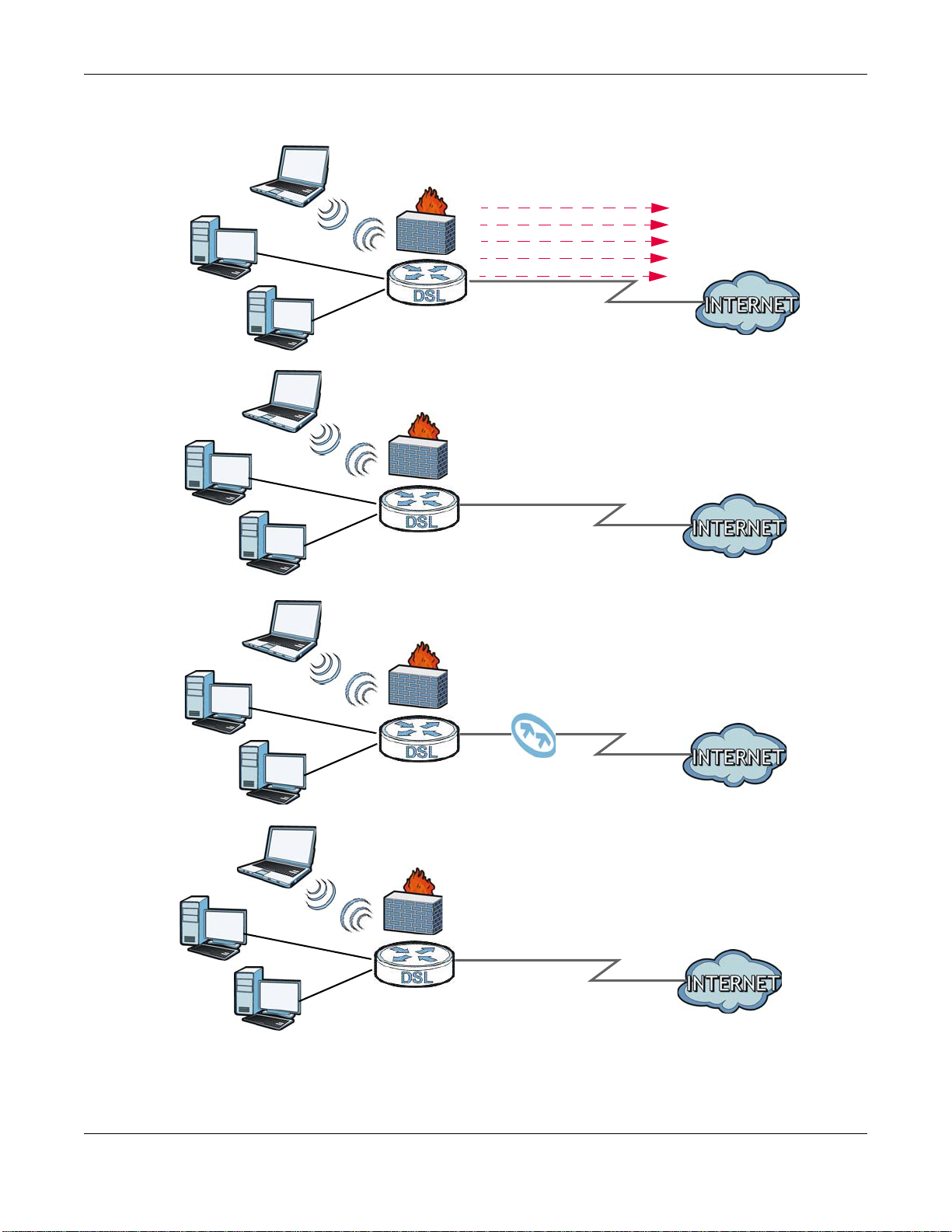
1.2.1 Internet Access
Your SBG3500-N Series provides multiple Internet access methods (up to two at a time), and you
can use them in the following combinations, if your ISP supports them.
SBG3500-N Series User’s Guide
17
Page 18

Chapter 1 Introducing the SBG3500-N Series
• ADSL2+ and VDSL, connect the DSL1 and/or DSL2 port using a phone cable to a DSL or MODEM
on a splitter or your telephone jack. For single DSL connection, use only DSL1 port. For DSL
bonding connection, use both DSL1 and DSL2 port at the same time. Refer to Section 6.2 on
page 104 for the Network Setting > Broadband screen. When using the DSL1/DSL2 ports
and VDSL connection is not available, then the ADSL2+ will automatically be the network
interface. You need to enable bonding feature if you want to use the bonding state. See (Section
6.5 on page 119) for details.
• DSL and GbE, connect the DSL port to the DSL or MODEM as described above and connect the
GbE port to a broadband router (if available) using an Ethernet cable. The 3G USB dongle is the
failover or a backup connection in case both the DSL and GbE fails. You can set the load balance
and failover in SBG3500-N Series to prioritize and redirect all traffic to the backup connection in
case the Internet access is down by clicking Network Settings > Broadband > Multi-WAN
• DSL and Fiber (SFP), connect the the DSL port to the DSL or MODEM and connect the SFP port
using a Fiber Optical module, also known as a mini-GBIC transceiver, to a Switch or Router. The
3G USB dongle is the failover or backup connection. Set load balance as described above and see
the SBG3500-N Series’s Quick Start Guide for details on how to install and remove a mini-GBIC
transceiver.
• DSL and 3G, connect the DSL port to the DSL or MODEM and connect the USB port using a USB
3G dongle. The Fiber/Ethernet is the failover. You can set the load balance/failover as described
above.
• Fiber and 3G, connect the SFP port using a mini-GBIC transceiver and the USB port using a USB
3G dongle as described above. The DSL is the failover in case both Fiber and 3G is unavailable.
• GbE and 3G, connect the GbE port to a broadband router and the USB port using a USB 3G
dongle. The DSL is the failover in case both Fiber and 3G is unavailable.
• WLAN or Wireless Internet access, Refer to Section 1.2.2 on page 20 for more information.
The below table is a summary of the SBG3500-N Series Multi-WAN combinations and failover.
DSL SFP/ETHERNET WAN 3G
Active Active Failover
Active Failover Active
Failover Active Active
The following figure shows the possible internet access scenarios described above.
Computers can connect to the SBG3500-N Series’s LAN ports (or wirelessly).
SBG3500-N Series User’s Guide
18
Page 19
Chapter 1 Introducing the SBG3500-N Series
ADSL2+/VDSL
WLAN
WAN
ADSL2+/VDSL and GbE
Load Balancing
WAN
LAN
LAN
WLAN
A
A
PPPoA
IPoE/IPoA
PPPoE
Bridging
WAN
ADSL2+/VDSL and Fiber
ADSL2+/VDSL and 3G
WAN
LAN
WLAN
A
A
Figure 1 SBG3500-N Series’s Internet Access Application
SBG3500-N Series User’s Guide
19
Page 20
Chapter 1 Introducing the SBG3500-N Series
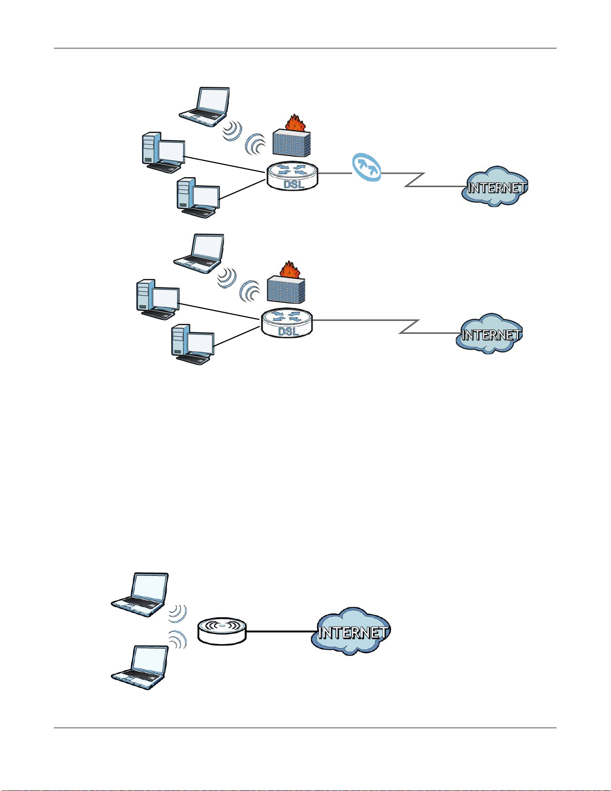
Fiber and 3G
WAN
LAN
WLAN
A
GbE and 3G
WAN
LAN
WLAN
A
Figure 2 SBG3500-N Series’s Internet Access Application (Continue)
1.2.2 Wireless LAN
You can also configure IP filtering on the SBG3500-N Series for secure Internet access. Go to
Security > MAC Filter to do this task. When the IP filter is on, all incoming traffic from the
Internet to your network is blocked by default unless it is initiated from your network. This means
that probes from the outside to your network are not allowed, but you can safely browse the
Internet and download files.
The SBG3500-N Series is a wireless Access Point (AP) for wireless clients, such as notebook
computers or PDAs and iPads. It allows them to connect to the Internet without having to rely on
inconvenient Ethernet cables.
You can configure your wireless network in either the built-in Web Configurator.
Figure 3 Wireless Access Example
SBG3500-N Series User’s Guide
20
Page 21
Chapter 1 Introducing the SBG3500-N Series
B
A
Using the WLAN Button
If the wireless network is turned off, press the WLAN button at the back of the SBG3500-N Series.
Once the WLAN LED turns green, the wireless network is active.
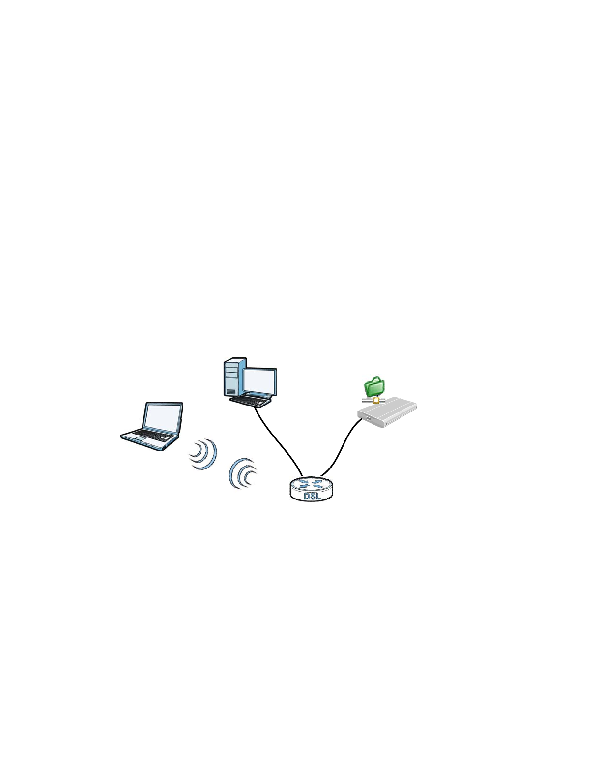
1.2.3 SBG3500-N Series’s USB Support
The USB port of the SBG3500-N Series is used for 3G Dongle and file-sharing.
3G Dongle
See the product page on ZyXEL’s website for the list of 3G Dongles that are compatible. To set up a
new 3G Dongle, click Network Settings > Broadband > 3G WAN, and to add new 3G Dongle,
click Network Settings > Broadband > Add new 3G Dongle.
File Sharing
Use the built-in USB 2.0 port to share files on a USB memory stick or a USB hard drive (B). You can
connect one USB hard drive to the SBG3500-N Series at a time. Use FTP to access the files on the
USB device.
Figure 4 USB File Sharing Application
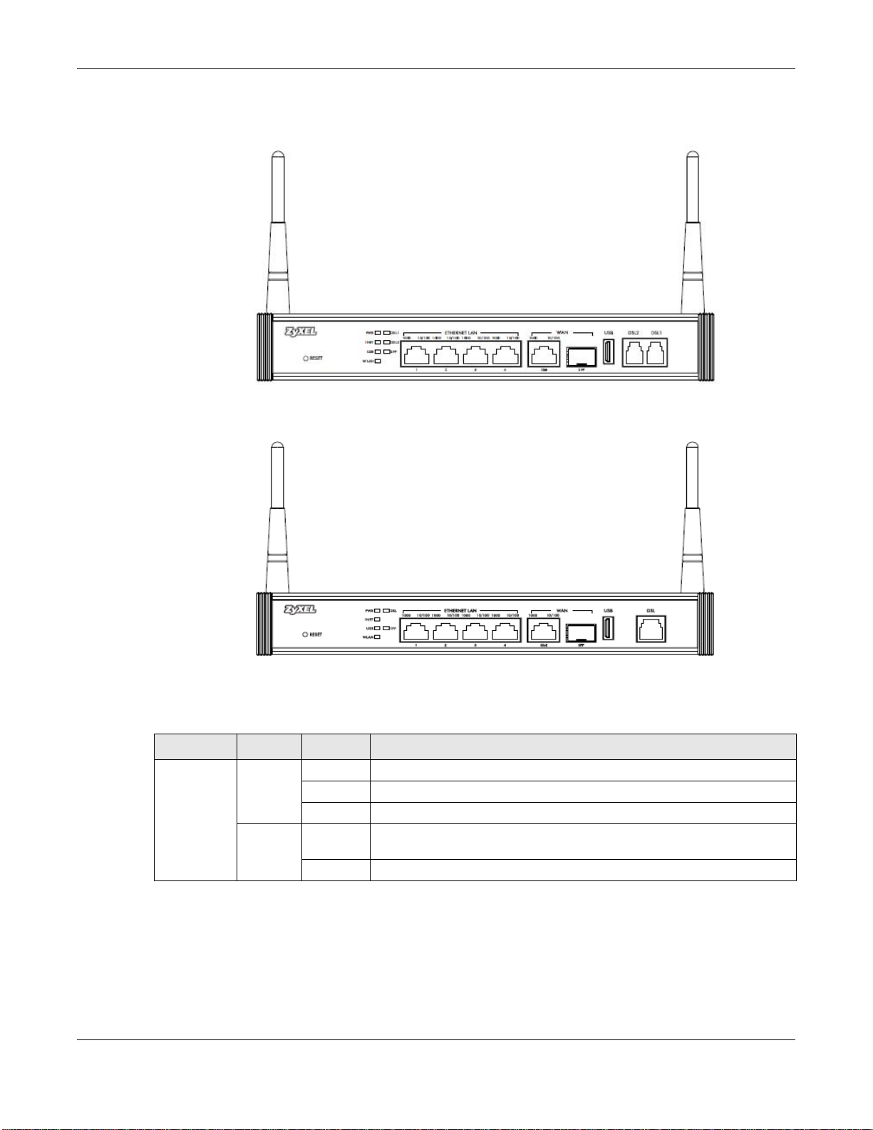
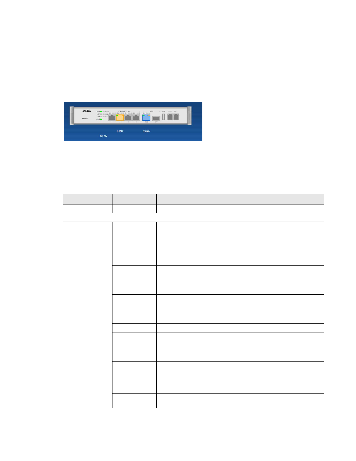
1.3 LEDs (Lights)
The following graphic displays the labels of the LEDs.
SBG3500-N Series User’s Guide
21
Page 22
Chapter 1 Introducing the SBG3500-N Series
SBG3500-NB00
SBG3500-N000
Figure 5 LEDs on the Device
None of the LEDs are on if the SBG3500-N Series is not receiving power.
Table 1 LED Descriptions
LED COLOR STATUS DESCRIPTION
POWER Green On The SBG3500-N Series is receiving power and ready for use.
Blinking The SBG3500-N Series is self-testing.
Off The SBG3500-N Series is not receiving power.
Red On The SBG3500-N Series detected an error while self-testing, or there is a
device malfunction.
Off The SBG3500-N Series is not receiving power.
SBG3500-N Series User’s Guide
22
Page 23

Chapter 1 Introducing the SBG3500-N Series
Table 1 LED Descriptions (continued)
LED COLOR STATUS DESCRIPTION
ETHERNET
LAN 1-4
ETHERNET
WAN
DSL1 and
DSL2
(SBG3500N000)
DSL1
(SBG3500NB00)
SFP Green On The Fiber connection is working.
INTERNET Green On The SBG3500-N Series has an IP connection but no traffic.
Left LED
(1000)
Green
Right
LED (10/
100)
Orange
Left LED
(1000)
Green
Right
LED (10/
100)
Orange
Green On The ADSL2+ line is up.
Orange On The VDSL line is up.
On The SBG3500-N Series has a successful Ethernet connection with a
device on the Local Area Network (LAN).
Blinking The SBG3500-N Series is sending or receiving data to/from the LAN.
Off The SBG3500-N Series does not have an Ethernet connection with the
LAN.
On The SBG3500-N Series has a successful Ethernet connection with a
device on the Local Area Network (LAN).
Blingking The SBG3500-N Series is sending or receiving data to/from the LAN.
Off The SBG3500-N Series does not have an Ethernet connection with the
LAN.
On The Gigabit Ethernet connection is working.
Blinking The SBG3500-N Series is sending or receiving data to/from the Gigabit
Ethernet link.
Off There is no Gigabit Ethernet link.
On The Gigabit Ethernet connection is working.
Blinking The SBG3500-N Series is sending or receiving data to/from the Gigabit
Ethernet link.
Off There is no Gigabit Ethernet link.
Blinking The SBG3500-N Series is initializing the ADSL2+ line.
Off The ADSL2+ line is down.
Blinking The SBG3500-N Series is initializing the VDSL line.
Off The VDSL line is down.
Blinking The SBG3500-N Series is sending or receiving data to/from the Fiber
link.
Off There is no Fiber link.
Your device has a WAN IP address (either static or assigned by a DHCP
server), PPP negotiation was successfully completed (if used) and the
DSL connection is up.
Blinking The SBG3500-N Series is sending or receiving IP or 3G traffic.
Off There is no Internet connection or the gateway is in bridged mode.
Red On The SBG3500-N Series failed to establish an IP connection.
No WAN IP address (either static or assigned by a DHCP server), PPPoE
negotiation failed (if used) and there’s no DSL connection.
USB Green On The SBG3500-N Series recognizes a 3G/USB connection.
Blinking The SBG3500-N Series is sending/receiving data to /from the USB
device connected to it.
Off The SBG3500-N Series does not detect a USB connection.
WLAN Green On The wireless network is activated.
Blinking The SBG3500-N Series is communicating with other wireless clients and
Off The wireless network is not activated.
is setting up a WPS connection.
SBG3500-N Series User’s Guide
23
Page 24

Chapter 1 Introducing the SBG3500-N Series
1.4 Ways to Manage the SBG3500-N Series
Use any of the following methods to manage the SBG3500-N Series.
• Web Configurator. This is recommended for everyday management of the SBG3500-N Series
using a (supported) web browser.
• TR-069. This is an auto-configuration server used to remotely configure your SBG3500-N Series.
1.5 Good Habits for Managing the SBG3500-N Series
Do the following things regularly to make the SBG3500-N Series more secure and to manage the
SBG3500-N Series more effectively.
• Change the password. Use a password that’s not easy to guess and that consists of different
types of characters, such as numbers and letters. The password must have at least six
characters.
• Write down the password and put it in a safe place.
• Back up the configuration (and make sure you know how to restore it). Restoring an earlier
working configuration may be useful if the device becomes unstable or even crashes. If you
forget your password, you will have to reset the SBG3500-N Series to its factory default settings.
If you backed up an earlier configuration file, you would not have to totally re-configure the
SBG3500-N Series. You could simply restore your last configuration.
1.6 The RESET Button
If you forget your password or cannot access the web configurator, you will need to use the RESET
button at the front of the device to reload the factory-default configuration file. This means that you
will lose all configurations that you had previously and the password will be reset to “1234”.
1 Make sure the POWER LED is on (not blinking).
2 To set the device back to the factory default settings, press the RESET button for ten seconds or
until the POWER LED begins to blink and then release it. When the POWER LED begins to blink,
the defaults have been restored and the device restarts.
SBG3500-N Series User’s Guide
24
Page 25

2.1 Overview
The web configurator is an HTML-based management interface that allows easy device setup and
management of the SBG3500-N Series via Internet browser. Use Internet Explorer 8.0 and later
versions with JavaScript enabled, or Mozilla Firefox 3 and later versions or Safari 2.0 and later
versions or Google Chrome and later versions. The recommended screen resolution is 1024 by 768
pixels.
In order to use the web configurator you need to allow:
• Web browser pop-up windows from your device. Web pop-up blocking is enabled by default in
Windows XP SP (Service Pack) 2.
• JavaScript (enabled by default).
• Java permissions (enabled by default).
CHAPTER 2
The Web Configurator
See Appendix C on page 387 if you need to make sure these functions are allowed in Internet
Explorer.
2.1.1 Accessing the Web Configurator
1 Make sure your SBG3500-N Series hardware is properly connected (refer to the Quick Start Guide).
2 Launch your web browser. If the SBG3500-N Series does not automatically re-direct you to the
login screen, go to http://192.168.1.1.
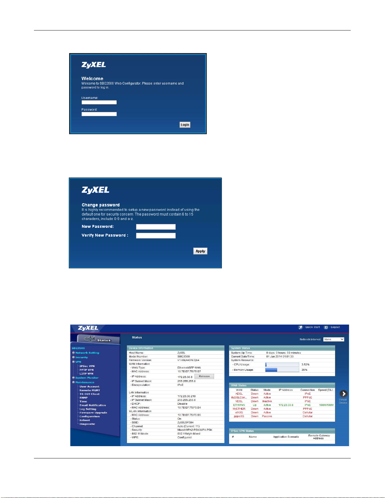
3 A password screen displays. To access the administrative web configurator and manage the
SBG3500-N Series, type the default username admin and password 1234 in the password screen
and click Login. If advanced account security is enabled (see Section 33.2 on page 325) the
number of dots that appears when you type the password changes randomly to prevent anyone
watching the password field from knowing the length of your password. If you have changed the
password, enter your password and click Login.
SBG3500-N Series User’s Guide
25
Page 26
Chapter 2 The Web Configurator
Figure 6 Password Screen
4 The following screen displays prompting you to change the password. It is strongly recommended
you change the default password. Enter a new password, minding the rules in the screen, retype it
to confirm and click Apply.
Figure 7 Change Password Screen
5 The Password screen re-appears. Enter the new password and click Login. Next, Status page
appears, where you can view the SBG3500-N Series’s interface and system information.
6 Click the Quick Start Wizard button on top of the page to configure the SBG3500-N Series’s time
zone, basic Internet access, and wireless settings. See Chapter 3 on page 32 for more information.
Figure 8 Status
SBG3500-N Series User’s Guide
26
Page 27
Chapter 2 The Web Configurator
B
C
A
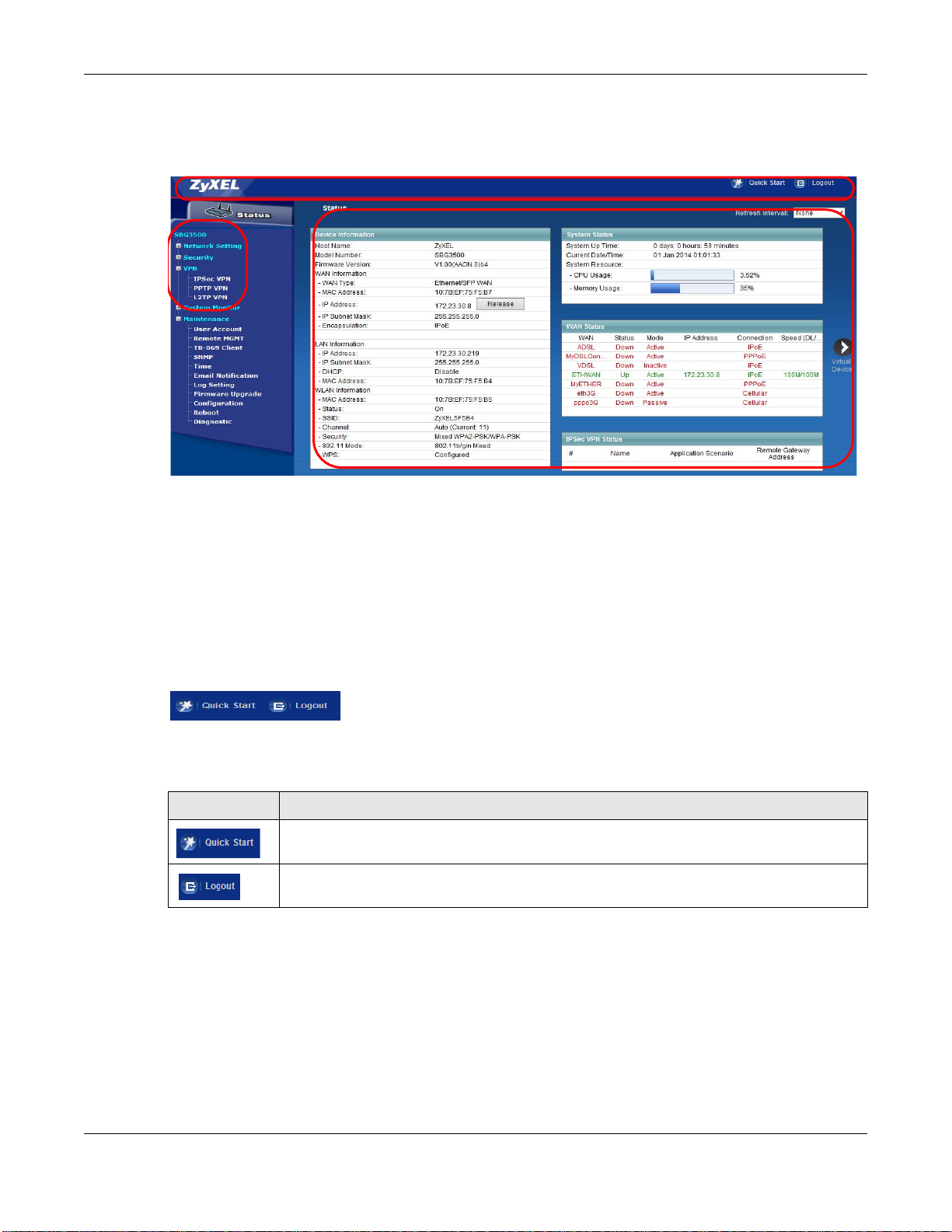
2.2 Web Configurator Layout
Figure 9 Screen Layout
As illustrated above, the main screen is divided into these parts:
• A - title bar
• B - main window
• C - navigation panel
2.2.1 Title Bar
The title bar provides some icons in the upper right corner.
The icons provide the following functions.
Table 2 Web Configurator Icons in the Title Bar
ICON DESCRIPTION
Quick Start: Click this icon to open screens where you can configure the SBG3500-N
Series’s time zone Internet access, and wireless settings.
Logout: Click this icon to log out of the web configurator.
SBG3500-N Series User’s Guide
27
Page 28
2.2.2 Main Window
The main window displays information and configuration fields. It is discussed in the rest of this
document. See Chapter 5 on page 97 for more information about the Status screen.
If you click Virtual Device on the System Info screen, a graphic shows the connection status of
the Device’s ports. The connected interfaces are in color and disconnected interfaces are gray.
Figure 10 Virtual Device
2.2.3 Navigation Panel
Use the menu items on the navigation panel to open screens to configure SBG3500-N Series
features. The following tables describe each menu item.
Table 3 Navigation Panel Summary
LINK TAB FUNCTION
Status Click this to go to the main Web Configurator screen.
Network Setting
Broadband Broadband Use this screen to view and configure ISP parameters, WAN IP
3G WAN Use this screen to configure 3G WAN connection.
Add New 3G
Dongle
Advanced Use this screen to enable or disable PTM over ADSL, Annex M, and
802.1x Use this screen to view and configure the IEEE 802.1x settings on the
Multi-WAN Use this screen to configure the multiple WAN load balance and fail-
Wireless General Use this screen to configure the wireless LAN settings and WLAN
More AP Use this screen to configure multiple BSSs on the SBG3500-N Series.
MAC
Authentication
WPS Use this screen to configure and view your WPS (Wi-Fi Protected
WMM Use this screen to enable or disable Wi-Fi MultiMedia (WMM).
Others Use this screen to configure advanced wireless settings.
Channel Status Use this screen to scan wireless LAN channel noises and view the
Scheduling Use this screen to set a schedule to turn off wireless LAN for power
Chapter 2 The Web Configurator
address assignment, and other advanced properties. You can also add
new WAN connections.
Use this screen to view or add a new 3G dongle.
DSL PhyR functions.
Device.
over rules to distribute traffic among different interfaces.
authentication/security settings.
Use this screen to block or allow wireless traffic from wireless devices
of certain SSIDs and MAC addresses to the SBG3500-N Series.
Setup) settings.
results.
saving purposes.
SBG3500-N Series User’s Guide
28
Page 29

Chapter 2 The Web Configurator
Table 3 Navigation Panel Summary (continued)
LINK TAB FUNCTION
LAN LAN Setup Use this screen to configure LAN TCP/IP settings, and other advanced
properties.
Static DHCP Use this screen to assign specific IP addresses to individual MAC
addresses.
UPnP Use this screen to turn UPnP and UPnP NAT-T on or off.
Additional
Subnet
5th Ethernet
Port
Routing Static Route Use this screen to view and set up static routes on the SBG3500-N
Policy
Forwarding
RIP
QoS General Use this screen to enable QoS and traffic prioritizing. You can also
Queue Setup Use this screen to configure QoS queues.
Class Setup Use this screen to define a classifier.
Policer Setup Use these screens to configure QoS policers.
Monitor Use this screen to view QoS packets statistics.
NAT Port Forwarding Use this screen to make your local servers visible to the outside
Applications Use this screen to configure servers behind the SBG3500-N Series.
Port Triggering Use this screen to change your SBG3500-N Series’s port triggering
Default Server Use this screen to configure a default server which receives packets
ALG Use this screen to enable or disable NAT ALG and SIP ALG.
Address Mapping Use this screen to change your Device’s address mapping settings.
DNS DNS Entry Use this screen to view and configure DNS routes.
Dynamic DNS Use this screen to allow a static hostname alias for a dynamic IP
Interface
Group/VLAN
USB Service USB Service Use this screen to enable file sharing via the SBG3500-N Series.
Security
Firewall General Use this screen to configure the security level of your firewall.
MAC Filter MAC Filter Use this screen to block or allow traffic from devices of certain MAC
User Access
Control
Interface Group/
VLAN
Service Use this screen to add Internet services and configure firewall rules.
Access Control Use this screen to enable specific traffic directions for network
DoS Use this screen to activate protection against Denial of Service (DoS)
User Access
Control
Use this screen to configure IP alias and public static IP.
Use this screen to configure the Ethernet WAN port as a LAN port.
Series.
Use this screen to configure policy routing on the SBG3500-N Series.
Use this screen to set up RIP settings on the SBG3500-N Series.
configure the QoS rules and actions.
world.
settings.
from ports that are not specified in the Port Forwarding screen.
address.
Use this screen to create a new interface group, which is a new LAN
bridge interface (subnet).
services.
attacks.
addresses to the SBG3500-N Series.
Use this screen to block web sites with the specific URL.
SBG3500-N Series User’s Guide
29
Page 30

Chapter 2 The Web Configurator
Table 3 Navigation Panel Summary (continued)
LINK TAB FUNCTION
Scheduler Rule Scheduler Rule Use this screen to configure the days and times when a configured
restriction (such as User Access control) is enforced.
Certificates Local Certificates Use this screen to view a summary list of certificates and manage
certificates and certification requests.
Trusted CA
VPN
IPSec VPN Setup Use this screen to display and manage the SBG3500-N Series’s IPSec
Monitor Use this screen to display and manage active IPSec VPN connections.
Radius Use this screen to manage the list of RADIUS servers the SBG3500-N
PPTP VPN Setup Use this screen to configure the PPTP VPN settings in the SBG3500-N
Monitor Use this screen to view settings for PPTP clients.
L2TP VPN Setup Use this screen to configure the SBG3500-N Series’s L2TP VPN
Monitor Use this screen to view settings for L2TP clients.
System Monitor
Log System Log Use this screen to view the status of events that occurred to the
Security Log Use this screen to view the login record of the SBG3500-N Series. You
Network Status WAN Use this screen to view the status of all network traffic going through
LAN Use this screen to view the status of all network traffic going through
DHCP Client Use this screen to view the status of all wired and wireless devices
ARP Table ARP Table Use this screen to view the ARP table. It displays the IP and MAC
Routing Table Routing Table Use this screen to view the routing table.
IGMP Group
Status
xDSL Statistics xDSL Statistics Use this screen to view the Device’s xDSL traffic statistics.
Maintenance
User Account User Account Use this screen to manage user accounts, which includes configuring
Remote MGMT Remote MGMT Use this screen to enable specific traffic directions for network
TR-069 Client TR-069 Clients Use this screen to configure the SBG3500-N Series to be managed by
SNMP SNMP Use this screen to enable/disable and configure settings for SNMP.
Time Time Use this screen to change your SBG3500-N Series’s time and date.
Email
Notification
IGMP Group
Status
Email
Notification
Use this screen to view and manage the list of the trusted CAs.
VPN rules (tunnels).
Series can use in authenticating users.
Series.
settings.
SBG3500-N Series. You can export or e-mail the logs.
can export or e-mail the logs.
the WAN port of the SBG3500-N Series.
the LAN ports of the SBG3500-N Series.
connected to the SBG3500-N Series. You can also set screen refresh
time to see updates on new devices.
address of each DHCP connection.
Use this screen to view the status of all IGMP settings on the
SBG3500-N Series.
the username, password, retry times, file sharing, captive portal, and
customizing the login message.
services.
an Auto Configuration Server (ACS).
Use this screen to configure up to two mail servers and sender
addresses on the SBG3500-N Series.
SBG3500-N Series User’s Guide
30
Page 31

Chapter 2 The Web Configurator
Table 3 Navigation Panel Summary (continued)
LINK TAB FUNCTION
Log Setting Log Setting Use this screen to change your SBG3500-N Series’s log settings.
Firmware
Upgrade
Configuration Configuration Use this screen to backup and restore your device’s configuration
Reboot Reboot Use this screen to reboot the SBG3500-N Series without turning the
Diagnostic Ping &
Firmware
Upgrade
Trac e route &
Nslookup
802.1ag Use this screen to configure CFM (Connectivity Fault Management)
OAM Ping Use this screen to view information to help you identify problems with
Use this screen to upload firmware to your device.
(settings) or reset the factory default settings.
power off.
Use this screen to identify problems with the DSL connection. You can
use Ping, TraceRoute, or Nslookup to help you identify problems.
MD (maintenance domain) and MA (maintenance association),
perform connectivity tests and view test reports.
the DSL connection.
SBG3500-N Series User’s Guide
31
Page 32

3.1 Overview
Use the Quick Start screens to configure the SBG3500-N Series’s time zone, basic Internet access,
and wireless settings.
Note: See the technical reference chapters (starting on page 96) for background
information on the features in this chapter.
3.2 Quick Start Setup
1 The Quick Start Wizard appears automatically after login. Or you can click the Click Start icon in
the top right corner of the web configurator to open the quick start screens. Select the time zone of
the SBG3500-N Series’s location and click Next.
Figure 11 Time Zone
CHAPTER 3
Quick Start
2 Select your current WAN interface to configure its settings.
SBG3500-N Series User’s Guide
32
Page 33

Figure 12 WAN Interface Selection
Chapter 3 Quick Start
3 Enter your Internet connection information in this screen. The screen and fields to enter may vary
depending on your current connection type. Click Next.
Figure 13 Internet Connection
4 Turn the wireless LAN on or off. If you keep it on, record the security settings so you can configure
your wireless clients to connect to the SBG3500-N Series. Click Save.
SBG3500-N Series User’s Guide
33
Page 34

Figure 14 Internet Connection
Chapter 3 Quick Start
5 Your SBG3500-N Series saves your settings and attempts to connect to the Internet.
SBG3500-N Series User’s Guide
34
Page 35

4.1 Overview
This chapter shows you how to use the SBG3500-N Series’s various features.
• Setting Up an ADSL PPPoE Connection, see page 35
• Setting Up a GbE WAN connection, see page 38
• Setting Up a 3G WAN connection, see page 40
• Setting Up a Secure Wireless Network, see page 40
• Setting Up Multiple Wireless Groups, see page 48
• Configuring Static Route for Routing to Another Network, see page 51
• Configuring QoS Queue and Class Setup, see page 54
• Access the SBG3500-N Series Using DDNS, see page 57
• Configuring the MAC Address Filter, see page 58
• Access Your Shared Files From a Computer, see page 60
• Certificate Configuration for VPN, see page 61
• Examples of Configuring IPSec VPN Rules, see page 64
• PPTP VPN Tutorial, see page 69
• L2TP VPN Tutorial, see page 81
CHAPTER 4
Tutorials
4.2 Setting Up an ADSL PPPoE Connection
This tutorial shows you how to set up your Internet connection using the Web Configurator.
If you connect to the Internet through an ADSL connection, use the information from your Internet
Service Provider (ISP) to configure the SBG3500-N Series. Be sure to contact your service provider
for any information you need to configure the Broadband screens.
1 Click Network Setting > Broadband to open the following screen. Click Add New WAN
Interface.
SBG3500-N Series User’s Guide
35
Page 36

Chapter 4 Tutorials
2 In this example, the DSL connection has the following information.
General
Name MyDSLConnection
Type ADSL
Connection Mode Routing
Encapsulation PPPoE
IPv6/IPv4 Mode IPv4
ATM PVC Configuration
VPI/VCI 36/48
Encapsulation Mode LLC/SNAP-Bridging
Service Category UBR without PCR
Account Information
PPP User Name 1234@DSL-Ex.com
PPP Password ABCDEF!
PPPoE Service Name MyDSL
Static IP Address 192.168.1.32
Others PPPoE Passthrough: Disabled
NAT: Enabled
IGMP Multicast Proxy: Enabled
Apply as Default Gateway: Enabled
3 Select the Active check box. Enter the General and ATM PVC Configuration settings as provided
above.
Set the Type to ADSL over ATM.
Choose the Encapsulation specified by your DSL service provider. For this example, the service
provider requires a username and password to establish Internet connection. Therefore, select
PPPoE as the WAN encapsulation type.
Set the IPv6/IPv4 Mode to IPv4 Only.
4 Enter the account information provided to you by your DSL service provider.
5 Configure this rule as your default Internet connection by selecting the Apply as Default Gateway
check box. Then select DNS as Static and enter the DNS server addresses provided to you, such as
192.168.5.2
(DNS server1)/192.168.5.1 (DNS server2).
6 Leave the rest of the fields to the default settings.
7 Click Apply to save your settings.
SBG3500-N Series User’s Guide
36
Page 37

Chapter 4 Tutorials
8 You should see a summary of your new DSL connection setup in the Broadband screen as follows.
SBG3500-N Series User’s Guide
37
Page 38

Chapter 4 Tutorials
Try to connect to a website to see if you have correctly set up your Internet connection. Be sure to
contact your service provider for any information you need to configure the WAN screens.
4.3 Setting Up a GbE WAN connection
This tutorial shows you how to set up your Gigabit Ethernet WAN connection using the Web
Configurator.
If you connect to the Internet through an Ethernet connection, use the information from your
Internet Service Provider (ISP) to configure the SBG3500-N Series. Be sure to contact your service
provider for any information you need to configure the Broadband screens.
1 Click Network Setting > Broadband to open the following screen.
2 Next, click Add New WAN Interface to open the following screen.
SBG3500-N Series User’s Guide
38
Page 39

Chapter 4 Tutorials
In this example, the Ethernet connection has the following information.
General
Name MyETHER
Type Eth ernet
Mode Routing
Service and
Encapsulation
IPv6/IPv4 Mode IPv4
Account Information
802.1p 0
802.1q 1
QoS 300 kbps
PPPoE
SBG3500-N Series User’s Guide
39
Page 40

Chapter 4 Tutorials
PPP User Name 1234@ETHER-Ex.com
PPP Password ABCDEF!
PPP Auto Connect Enabled
PPPoE Service name ethertest
PPPoE Passthrough Enabled
MTU 1492
IP Address 192.168.1.40
Primary DNS Server 192.168.5.5
Secondary DNS Server 192.168.5.6
Others PPPoE Passthrough: Disabled
NAT: Enabled
IGMP Multicast Proxy: Enabled
Apply as Default Gateway: Enabled
You should see a summary of your new Ethernet connection setup in the Broadband screen as
follows.
4.4 Setting Up a 3G WAN connection
See the 3G WAN screen (Section 6.3 on page 114) for setting up a 3G WAN connection. Make sure
you
insert a valid SIM card (with active data plan) into the 3G USB dongle before you inser the USB
dongle to the USB port of your computer.
4.5 Setting Up a Secure Wireless Network
Thomas wants to set up a wireless network so that he can use his notebook to access the Internet.
In this wireless network, the SBG3500-N Series serves as an access point (AP), and the notebook is
the wireless client. The wireless client can access the Internet through the AP.
SBG3500-N Series User’s Guide
40
Page 41

Chapter 4 Tutorials
Thomas has to configure the wireless network settings on the SBG3500-N Series. Then he can set
up a wireless network using WPS (Section 4.5.2 on page 43) or manual configuration (Section 4.5.3
on page 47).
4.5.1 Configuring the Wireless Network Settings
This example uses the following parameters to set up a wireless network.
SSID Example
Security Mode WPA-PSK
Pre-Shared Key DoNotStealMyWirelessNetwork
802.11 Mode 802.11b/g/n Mixed
1 Click Network Setting > Wireless to open the General screen. Select More Secure as the
security level and WPA2-PSK as the security mode. Configure the screen using the provided
parameters (see page 41). Click Apply.
SBG3500-N Series User’s Guide
41
Page 42

Chapter 4 Tutorials
2 Go to the Wireless > Others screen and select 802.11b/g/n Mixed in the 802.11 Mode field.
Click Apply.
SBG3500-N Series User’s Guide
42
Page 43

Thomas can now use the WPS feature to establish a wireless connection between his notebook and
the SBG3500-N Series (see Section 4.5.2 on page 43). He can also use the notebook’s wireless
client to search for the SBG3500-N Series (see Section 4.5.3 on page 47).
4.5.2 Using WPS
This section shows you how to set up a wireless network using WPS. It uses the SBG3500-N Series
as the AP and ZyXEL NWD210N as the wireless client which connects to the notebook.
Note: The wireless client must be a WPS-aware device (for example, a WPS USB adapter
or PCMCIA card).
There are two WPS methods to set up the wireless client settings:
• Push Button Configuration (PBC) - simply press a button. This is the easier of the two
methods.
• PIN Configuration - configure a Personal Identification Number (PIN) on the SBG3500-N
Series. A wireless client must also use the same PIN in order to download the wireless network
settings from the SBG3500-N Series.
Push Button Configuration (PBC)
Chapter 4 Tutorials
1 Make sure that your SBG3500-N Series is turned on and your notebook is within the cover range of
the wireless signal.
2 Make sure that you have installed the wireless client driver and utility in your notebook.
3 In the wireless client utility, go to the WPS setting page. Enable WPS and press the WPS button
(Start or WPS button).
4 Log into SBG3500-N Series’s web configurator and go to the Network Setting > Wireless > WPS
screen. Enable the WPS function and click Apply. Then click the Connect button.
Note: You must enable the Wireless function in the Network Setting > Wireless >
General screen before you can enable the WPS function.
SBG3500-N Series User’s Guide
43
Page 44

Chapter 4 Tutorials
Note: Your SBG3500-N Series has a WPS button located on its front panel as well as a
WPS button in its configuration utility. Both buttons have exactly the same
function: you can use one or the other.
Note: It doesn’t matter which device’s WPS you enable first, but you must enable the
second device’s WPS within two minutes of enabling the first one.
The SBG3500-N Series sends the proper configuration settings to the wireless client. This may take
up to two minutes. The wireless client is then able to communicate with the SBG3500-N Series
securely.
The following figure shows you an example of how to set up a wireless network and its security.
SBG3500-N Series User’s Guide
44
Page 45

Example WPS Process: PBC Method
Wireless Client
Device
SECURITY INFO
COMMUNICATION
WITHIN 2 MINUTES
Click “Connect”
Chapter 4 Tutorials
PIN Configuration
When you use the PIN configuration method, you need to use both the SBG3500-N Series’s web
configurator and the wireless client’s utility.
1 Launch your wireless client’s configuration utility. Go to the WPS settings and select the PIN method
to get a PIN number.
2 Log into SBG3500-N Series’s web configurator and go to the Network Setting > Wireless > WPS
screen. Enable the WPS function and click Apply.
SBG3500-N Series User’s Guide
45
Page 46

Chapter 4 Tutorials
3 Enter the PIN number of the wireless client and click the Register button. Activate WPS function on
the wireless client utility screen within two minutes.
The SBG3500-N Series authenticates the wireless client and sends the proper configuration settings
to the wireless client. This may take up to two minutes. The wireless client is then able to
communicate with the SBG3500-N Series securely.
The following figure shows you how to set up a wireless network and its security on a SBG3500-N
Series and a wireless client by using PIN method.
SBG3500-N Series User’s Guide
46
Page 47

Example WPS Process: PIN Method
Authentication by PIN
SECURITY INFO
WITHIN 2 MINUTES
Wireless Client
ZyXEL Device
COMMUNICATION
Chapter 4 Tutorials
4.5.3 Without WPS
Use the wireless adapter’s utility installed on the notebook to search for the “Example” SSID. Then
enter the “DoNotStealMyWirelessNetwork” pre-shared key to establish an wireless Internet
connection.
Note: The SBG3500-N Series supports IEEE 802.11b, IEEE 802.11g, and IEEE 802.11n
wireless clients. Make sure that your notebook or computer’s wireless adapter
supports one of these standards.
SBG3500-N Series User’s Guide
47
Page 48

Chapter 4 Tutorials
Company
VIP
Guest
4.6 Setting Up Multiple Wireless Groups
Company A wants to create different wireless network groups for different types of users as shown
in the following figure. Each group has its own SSID and security mode.
• Employees in Company A will use a general Company wireless network group.
• Higher management level and important visitors will use the VIP group.
• Visiting guests will use the Guest group, which has a lower security mode.
Company A will use the following parameters to set up the wireless network groups.
COMPANY VIP GUEST
SSID Company VIP Guest
Security Level More Secure More Secure Basic
Security Mode WPA2-PSK WPA2-PSK Static WEP
Pre-Shared Key ForCompanyOnly ForVIPOnly Guest12345678
1 Click Network Setting > Wireless to open the General screen. Use this screen to set up the
company’s general wireless network group. Configure the screen using the provided parameters
and click Apply.
SBG3500-N Series User’s Guide
48
Page 49

Chapter 4 Tutorials
2 Click Network Setting > Wireless > More AP to open the following screen. Click the Edit icon to
configure the second wireless network group.
3 Configure the screen using the provided parameters and click Apply.
SBG3500-N Series User’s Guide
49
Page 50

Chapter 4 Tutorials
4 In the More AP screen, click the Edit icon to configure the third wireless network group.
5 Configure the screen using the provided parameters and click Apply.
SBG3500-N Series User’s Guide
50
Page 51

Chapter 4 Tutorials
6 Check the status of VIP and Guest in the More AP screen. The yellow bulbs signify that the SSIDs
are active and ready for wireless access.
4.7 Configuring Static Route for Routing to Another Network
In order to extend your Intranet and control traffic flowing directions, you may connect a router to
the SBG3500-N Series’s LAN. The router may be used to separate two department networks. This
tutorial shows how to configure a static routing rule for two network routings.
SBG3500-N Series User’s Guide
51
Page 52

Chapter 4 Tutorials
N2
B
N1
A
R
N2
B
N1
A
R
In the following figure, router R is connected to the SBG3500-N Series’s LAN. R connects to two
networks, N1 (192.168.1.x/24) and N2 (192.168.10.x/24). If you want to send traffic from
computer A (in N1 network) to computer B (in N2 network), the traffic is sent to the SBG3500-N
Series’s WAN default gateway by default. In this case, B will never receive the traffic.
You need to specify a static routing rule on the SBG3500-N Series to specify R as the router in
charge of forwarding traffic to N2. In this case, the SBG3500-N Series routes traffic from A to R
and then R routes the traffic to B.
This tutorial uses the following example IP settings:
Table 4 IP Settings in this Tutorial
DEVICE / COMPUTER IP ADDRESS
The SBG3500-N Series’s WAN 172.16.1.1
The SBG3500-N Series’s LAN 192.168.1.1
IP Type IPv4
Use Interface ADSL/atm0
A 192.168.1.34
SBG3500-N Series User’s Guide
52
Page 53

Chapter 4 Tutorials
Table 4 IP Settings in this Tutorial
DEVICE / COMPUTER IP ADDRESS
R’s N1 192.168.1.253
R’s N2 192.168.10.2
B 192.168.10.33
To configure a static route to route traffic from N1 to N2:
1 Log into the SBG3500-N Series’s Web Configurator in advanced mode.
2 Click Network Setting > Routing.
3 Click Add new static route in the Static Route screen.
4 Configure the Static Route Setup screen using the following settings:
4a Select the Active check box. Enter the Route Name as R.
4b Set IP Type to IPv4.
4c Type 192.168.10.0 and subnet mask 255.255.255.0 for the destination, N2.
4d Select Enable in the Use Gateway IP Address field. Type 192.168.1.253 (R’s N1 address)
in the Gateway IP Address field.
4e Select ADSL/atm0 as the Use Interface.
4a Click OK.
Now B should be able to receive traffic from A. You may need to additionally configure B’s firewall
settings to allow specific traffic to pass through.
SBG3500-N Series User’s Guide
53
Page 54

Chapter 4 Tutorials
10,000 kbps
DSL
Your computer
IP=192.168.1.23
A colleague’s computer
Other traffic: Automatic classifier
and/or
MAC=AA:FF:AA:FF:AA:FF
Email traffic: Highest priority
4.8 Configuring QoS Queue and Class Setup
This section contains tutorials on how you can configure the QoS screen.
Let’s say you are a team leader of a small sales branch office. You want to prioritize e-mail traffic
because your task includes sending urgent updates to clients at least twice every hour. You also
upload data files (such as logs and e-mail archives) to the FTP server throughout the day. Your
colleagues use the Internet for research, as well as chat applications for communicating with other
branch offices.
In the following figure, your Internet connection has an upstream transmission bandwidth of
10,000 kbps. For this example, you want to configure QoS so that e-mail traffic gets the highest
priority with at least 5,000 kbps. You can do the following:
• Configure a queue to assign the highest priority queue (1) to e-mail traffic going to the WAN
interface, so that e-mail traffic would not get delayed when there is network congestion.
• Note the IP address (192.168.1.23 for example) and/or MAC address (AA:FF:AA:FF:AA:FF for
example) of your computer and map it to queue 7.
Note: QoS is applied to traffic flowing out of the SBG3500-N Series.
Traffic that does not match this class is assigned a priority queue based on the internal QoS
mapping table on the SBG3500-N Series.
QoS Example
1 Click Network Setting > QoS > General and select Enable. Set your WAN Managed Upstream
Bandwidth to 10,000 kbps (or leave this blank to have the SBG3500-N Series automatically
determine this figure). Click Apply.
SBG3500-N Series User’s Guide
54
Page 55

Chapter 4 Tutorials
Tutorial: Advanced > QoS
2 Click Queue Setup > Add new Queue to create a new queue. In the screen that opens, check
Active and enter or select the following values:
• Name: E-mail
• Interface: WAN
• Priority: 1 (High)
• Weight: 8
• Rate Limit: 5,000 (kbps)
Tutorial: Advanced > QoS > Queue Setup
3 Click Class Setup > Add new Classifier to create a new class. Check Active and follow the
settings as shown in the screen below.
SBG3500-N Series User’s Guide
55
Page 56

Tutorial: Advanced > QoS > Class Setup
Chapter 4 Tutorials
Class Name Give a class name to this traffic, such as E-mail in this example.
From
Interface
Ether Type Select IP to identify the traffic source by its IP address or MAC address.
IP Address Type the IP address of your computer - 192.168.1.23. Type the IP Subnet Mask if you
MAC Address Type the MAC address of your computer - AA:FF:AA:FF:AA:FF. Type the MAC Mask if you
To Queue
Index
This is the interface from which the traffic will be coming from. Select LAN1 for this
example.
know it.
know it.
Link this to an item in the Network Setting > QoS > Queue Setup screen, which is the E-
mail queue created in this example.
SBG3500-N Series User’s Guide
56
Page 57

Chapter 4 Tutorials
w.x.y.z
a.b.c.d
http://zyxelrouter.dyndns.org
A
This maps e-mail traffic coming from port 25 to the highest priority, which you have created in the
previous screen (see the IP Protocol field). This also maps your computer’s IP address and MAC
address to the E-mail queue (see the Source fields).
4 Verify that the queue setup works by checking Network Setting > QoS > Monitor. This shows
the bandwidth allotted to e-mail traffic compared to other network traffic.
4.9 Access the SBG3500-N Series Using DDNS
If you connect your SBG3500-N Series to the Internet and it uses a dynamic WAN IP address, it is
inconvenient for you to manage the device from the Internet. The SBG3500-N Series’s WAN IP
address changes dynamically. Dynamic DNS (DDNS) allows you to access the SBG3500-N Series
using a domain name.
To use this feature, you have to apply for DDNS service at www.dyndns.org.
This tutorial covers:
• Registering a DDNS Account on www.dyndns.org
• Configuring DDNS on Your SBG3500-N Series
• Testing the DDNS Setting
Note: If you have a private WAN IP address, then you cannot use DDNS.
4.9.1 Registering a DDNS Account on www.dyndns.org
1 Open a browser and type http://www.dyndns.org.
2 Apply for a user account. This tutorial uses UserName1 and 12345 as the username and
password.
3 Log into www.dyndns.org using your account.
4 Add a new DDNS host name. This tutorial uses the following settings as an example.
•Hostname: zyxelrouter.dyndns.org
•Service Type: Host with IP address
• IP Address: Enter the WAN IP address that your SBG3500-N Series is currently using. You can
find the IP address on the SBG3500-N Series’s Web Configurator Status page.
SBG3500-N Series User’s Guide
57
Page 58

Chapter 4 Tutorials
Then you will need to configure the same account and host name on the SBG3500-N Series later.
4.9.2 Configuring DDNS on Your SBG3500-N Series
Configure the following settings in the Network Setting > DNS > Dynamic DNS screen.
•Select Enable Dynamic DNS.
•Select www.DynDNS.com as the service provider.
•Type zyxelrouter.dyndns.org in the Host Name field.
• Enter the user name (UserName1) and password (12345).
Click Apply.
4.9.3 Testing the DDNS Setting
Now you should be able to access the SBG3500-N Series from the Internet. To test this:
1 Open a web browser on the computer (using the IP address a.b.c.d) that is connected to the
Internet.
2 Type http://zyxelrouter.dyndns.org and press [Enter].
3 The SBG3500-N Series’s login page should appear. You can then log into the SBG3500-N Series and
manage it.
4.10 Configuring the MAC Address Filter
Thomas noticed that his daughter Josephine spends too much time surfing the web and
downloading media files. He decided to prevent Josephine from accessing the Internet so that she
can concentrate on preparing for her final exams.
Josephine’s computer connects wirelessly to the Internet through the SBG3500-N Series. Thomas
decides to use the Security > MAC Filter screen to grant wireless network access to his computer
but not to Josephine’s computer.
SBG3500-N Series User’s Guide
58
Page 59

Chapter 4 Tutorials
Thomas
Josephine
1 Click Security > MAC Filter to open the MAC Filter screen. Select the Enable check box to
activate MAC filter function.
2 Select Allow. Then enter the host name and MAC address of Thomas’ computer in this screen. Click
Apply.
Thomas can also grant access to the computers of other members of his family and friends.
However, Josephine and others not listed in this screen will no longer be able to access the Internet
through the SBG3500-N Series.
SBG3500-N Series User’s Guide
59
Page 60

Chapter 4 Tutorials
4.11 Access Your Shared Files From a Computer
Here is how to enable the Samba feature on the SBG3500-N Series and access a file storage device
connected to the SBG3500-N Series’s USB port.
1 Log into the web configurator and go to the Maintenance > User Account screen. Click the Edit
icon on the account you are currently using. In this example, the account in use is admin. Click the
Edit icon next to it.
2 Set the File Sharing Service (SAMBA) feature to Enable to allow uses to access shared files in
USB storage. Enter mnt as the File Share Name. Click Apply.
3 In this example, the FileZilla program is used to browse shared files. In FileZilla, enter the IP
address of the SBG3500-N Series (the default is 192.168.1.1), your account’s user name and
password and port 21 and click Quickconnect. A screen asking for password authentication
appears.
SBG3500-N Series User’s Guide
60
Page 61

File Sharing via Windows Explore r
Chapter 4 Tutorials
4 Once you log in the USB device displays in the mnt folder.
4.12 Certificate Configuration for VPN
You may generate a self-signed Certification Authority (CA) certificate using a third party tool or get
an official CA certificate from any trusted certificate agent. In this tutorial, a self-signed CA
certificate (cacert.pem) was created by using the openssl command in Fedora 10.
1 First, you need to import the CA certificate. Go to the Security > Certificates > Trusted CA
screen and click Import Certificate.
2 Browse the directory in Fedora, or another system, which contains your CA certificate (e.g.,
cacert.pem), then click OK.
SBG3500-N Series User’s Guide
61
Page 62

Chapter 4 Tutorials
3 In the Security > Certificates > Local Certificates screen, click Create Certificate Request.
4 Enter your information as shown in the following screen and click Apply.
5 The contents of the certificate display in the View Certificate screen. Copy the Signing Request
section and paste it to a file (for example, sbg.req) in Fedora, or another system, which contains
your original CA certificate.
SBG3500-N Series User’s Guide
62
Page 63

Chapter 4 Tutorials
6 In Fedora, issue the following openssl command to generate the host certificate for the SBG3500-N
Series:
openssl ca -config ./openssl.conf -policy policy_anything -out sbg.pem
-infiles sbg.req
7 Click the Load_Signed button in the View Certificate screen.
8 Cut the contents of sbg.pem (only the binary portion between BEGIN CERTIFICATE and END
CERTIFICATE). You can use "vi" or your favorite text editor to cut the portion, but do not use the
"cat" command.
9 Paste it to the indicated part of the Certificate section in the View Certificate screen. Click
Apply.
SBG3500-N Series User’s Guide
63
Page 64

Chapter 4 Tutorials
10 Now you may configure VPN to use the new certificate for authentication in the VPN > IPSec VPN
> Monitor screen.
4.13 Examples of Configuring IPSec VPN Rules
The first two examples show how to configure Site-to-Site rules with pre-shared secrets. The first
example uses 3DES encryption and the second one uses AES128.
The third example shows how to configure a Site-to-Site with Dynamic Peer rule using pre-shared
secret keys.
Finally, the fourth example shows how to configure remote access using pre-shared secrets.
4.13.1 Example 1: Use 3DES Encryption
1 Click the Add New Entry button in the VPN > IPSec VPN > Setup screen and enter the following
parameters:
General
Connection Name vpn1
Application Scenario Site-to-Site
My Address ETHWAN
Peer Gateway Address 22.23.24.25
Authentication
Key Exchange Mode Auto
Pre-Shared Key 1234567890
Phase 1
SA Life Time 28800
Negotiation Mode Main
Encryption 3DES
SBG3500-N Series User’s Guide
64
Page 65

Chapter 4 Tutorials
Authentication SHA1
Key Group DH2
Phase 2
SA Life Time 3600
Tunnel Mode ESP
Encapsulation Tunnel
Encryption 3DES
Authentication SHA1
PFS DH2
Policy
Local IP Type Subnet
Local IP Address 192.168.1.0
Local Subnet Mask 255.255.255.0
Remote IP Type Subnet
Remote IP Address 172.23.9.0
Remote Subnet Mask 255.255.255.0
SBG3500-N Series User’s Guide
65
Page 66

Chapter 4 Tutorials
You can see the new IPSec VPN rule you’ve just created in the VPN > IPSec VPN > Monitor
screen.
SBG3500-N Series User’s Guide
66
Page 67

Chapter 4 Tutorials
4.13.2 Example 2: Use AES128 Encryption
Here is another example of creating a Gateway-to-Gateway IPSec VPN rule with pre-shared secrets.
1 Click the Add New Entry button in the VPN > IPSec VPN > Setup screen.
2 Enter vpn2 as the Connection Name. Remove the existing encryption by clicking Remove icon or
Reset button. Then select AES128 and click the Add button in the Encryption fields of phase 1
and 2. Other parameters are the same as example 1’s.
SBG3500-N Series User’s Guide
67
Page 68

Chapter 4 Tutorials
3 You can see the new IPSec VPN rule you’ve just created in the VPN > IPSec VPN > Monitor
screen.
4.13.3 Example 3: Configuring a Site-to-Site with Dynamic Peer Rule
Select Site-to-Site with Dynamic Peer in the Application Scenario field in the General
section. Other parameters are the same as example 1’s.
4.13.4 Example 4: Configuring a Remote Access Rule
Select Remote Access in the Application Scenario field in the General section. Other
parameters are the same as example 1’s.
Note: The Peer Gateway Address is not shown in the screen because it is an unknown
IP address to the remote access VPN client.
SBG3500-N Series User’s Guide
68
Page 69

Note: The policy for the remote VPN client is not shown in the screen because it is an
172.16.1.2
LAN Subnet #1: 192.168.1.0/24
LAN Subnet #2: 192.168.2.0/24
PPTP VPN IP Address Pool:
10.1.1.1 - 10.1.1.32
unknown to the remote access VPN client.
4.14 PPTP VPN Tutorial
The example uses the following settings in setting up a basic PPTP VPN tunnel.
Figure 15 PPTP VPN Example
Chapter 4 Tutorials
• The SBG3500-N Series has a static IP address of 172.16.1.2 for the DSL WAN interface.
• The remote user has a dynamic IP address and connects through the Internet.
• Use the default IP address pool to assign the remote users a point-to-point IP addresses from
10.1.1.1 to 10.1.1.32 for use in the PPTP VPN tunnel.
• The access group configuration allows the remote user to access only the LAN subnet #1
192.168.1.0/24.
4.14.1 Configuring PPTP VPN Setup (Server)
1.Go to the VPN > PPTP VPN > Setup screen and configure the following.
• Select the Enable checkbox.
•Set Access Group 1 to 192.168.1.0/255.255.255.0.
•Select DNS as User Defined and enter a DNS server address. The DNS server address in this
example is 8.8.8.8.
• Click Apply.
SBG3500-N Series User’s Guide
69
Page 70

Chapter 4 Tutorials
4.14.2 Configuring PPTP VPN on Windows (Client)
The following sections cover how to configure PPTP in remote user computers using Windows 7,
Vista and XP. The example settings in these sections match the PPTP VPN configuration example in
Section 4.14 on page 69.
On Windows 7
On Windows 7, do the following to establish a PPTP VPN connection.
1 Click Start > Control Panel > Network and Sharing Center > Setup a new connection or
network > Connect to a workplace. Click Next.
2 Select No, create a new connection. Click Next.
SBG3500-N Series User’s Guide
70
Page 71

Chapter 4 Tutorials
3 Select Use my Internet connection (VPN).
4 Enter the domain name or WAN IP Address that you want to connect to (172.16.1.2 in this
example) and give this connection a name. Select Don't connect now; just set it up so I can
connect later. Click Next.
SBG3500-N Series User’s Guide
71
Page 72

Chapter 4 Tutorials
5 Click Create. Enter the user name and password later.
6 Click Close. Do not connect yet.
SBG3500-N Series User’s Guide
72
Page 73

Chapter 4 Tutorials
7 Click the Network icon in your system tray, then click Connect to a Network and Sharing
Center on Windows 7.
8 Cick Change adapter settings.
9 Double-click the new connection icon.
SBG3500-N Series User’s Guide
73
Page 74

Chapter 4 Tutorials
10 The connection screen appears. Click Properties.
11 The Properties window appears. Click Security.
12 Select Point to Point Tunneling Protocol (PPTP) as the Type of VPN. Select Maximum
strength encryption (disconnect if server declines) and the Allow these protocols radio
button. Select Microsoft CHAP Version 2 (MS-CHAP v2) and clear all of the other check boxes.
Do not click OK yet.
SBG3500-N Series User’s Guide
74
Page 75

Chapter 4 Tutorials
13 In the Connect window, enter the username and password of your SBG3500-N Series’s account.
Click Connect.
Note: The user account must have been configured in the Maintenance > User
Account screen. Refer to Chapter 33 on page 325.
14 A window appears while the username and password are verified. The connection is then
established.
15 The Network and Sharing Center windows appear. You can view the connection status or
disconnect the connection. Click View Status to open the connection status screen.
SBG3500-N Series User’s Guide
75
Page 76

Chapter 4 Tutorials
16 Click the Network icon in your system tray, then right click the PPTP connection and select Status
to open the connection status screen.
17 From the status screen, you can disconnect this connection. Or you can click Details to see the
connection details. The address 10.1.1.1 and 10.1.1.17 are addresses allocated from the PPTP IP
Address Pool you configured on the SBG3500-N Series (10.1.1.1 - 10.1.1.32).
SBG3500-N Series User’s Guide
76
Page 77

Chapter 4 Tutorials
18 Access a server or other network resource on subnet 192.168.1.0 behind the SBG3500-N Series to
make sure your access works.
4.14.3 Configuring PPTP VPN on Android Devices (Client)
The following sections cover how to configure the built-in PPTP client in remote user’s Android
devices. Due to GUI difference among various Android devices, the figures may not exactly match
what your Android device displays. The example settings in these sections match the PPTP VPN
configuration example in Section 4.14 on page 69.
1 On your Android device, select Home > Settings > Wireless and network > VPN settings.
2 Select Add VPN > Add PPTP VPN.
SBG3500-N Series User’s Guide
77
Page 78

Chapter 4 Tutorials
3 Fill out the following fields.
• VPN Name: Enter a name for your VPN configuration.
• Set VPN Server: This is the WAN IP address of the SBG3500-N Series, in this example,
172.16.1.2
• Enable Encryption: checked.
• DNS search domains: not used.
4 The new configuration will appear on the VPN settings screen. You can click the VPN name to
begin PPTP connection.
5 Enter the username and password of your user account configured on the SBG3500-N Series.
Note: The user account must have been configured in the Maintenance > User
Account screen. Refer to Chapter 33 on page 325.
6 You can see Connected when the PPTP VPN connection has been established. Click the connection
name to get connection details. There you can also disconnect.
SBG3500-N Series User’s Guide
78
Page 79

Chapter 4 Tutorials
4.14.4 Configuring PPTP VPN in iOS Devices (Client)
The following sections cover how to configure the built-in PPTP client in iOS devices (iPhone, iPad,
iPod Touch, etc). Due to GUI difference among various iOS devices, the figures may not match what
your iOS device displays. The example settings in these sections match the PPTP VPN configuration
example in Section 4.14 on page 69.
1 On your iOS device, select Home > Settings > General > Network.
2 Select VPN > Add VPN Configuration….
SBG3500-N Series User’s Guide
79
Page 80

Chapter 4 Tutorials
3 Select the PPTP tab. Enter the following fields.
• Description: Enter a name for your VPN configuration.
• Server: This is the WAN IP address of the SBG3500-N Series, in this example, 172.16.1.2.
• Account: This is the user account created on SBG3500-N Series for accessing the network via
VPN.
• RSA SecurID: Not used in this configuration.
• Password: This is the password for account.
• Secret: This is your pre-shared key for your VPN connection, in this example, 1234567890.
• Send All Traffic: This example uses the route-all configuration (ON).
4 Save the configuration.
5 The saved configuration will appear on the VPN screen. Select it and then slide the VPN bar to the
ON position. Your iOS device will begin PPTP connection.
SBG3500-N Series User’s Guide
80
Page 81

4.15 L2TP VPN Tutorial
172.16.1.2
LAN Subnet #1: 192.168.1.0/24
LAN Subnet #2: 192.168.2.0/24
L2TP VPN IP Address Pool:
10.2.1.1 - 10.2.1.32
Chapter 4 Tutorials
This section illustrates how to set up a basic L2TP VPN tunnel between the SBG3500-N Series and a
remote client.
The example uses the following settings in setting up a basic L2TP VPN tunnel.
Figure 16 L2TP VPN Example
• The SBG3500-N Series has a static IP address of 172.16.1.2 for the DSL WAN interface.
• The remote user has a dynamic IP address and connects through the Internet.
• Use the default IP address pool to assign the remote users a point-to-point IP addresses from
10.2.1.1 to 10.2.1.32 for use in the L2TP VPN tunnel.
• The access group configuration allows the remote L2TP user to access only the LAN subnet
192.168.2.0/24.
4.15.1 Configuring the Default_L2TPVPN IPSec VPN Rule (Server)
1 Go to the VPN > IPSec VPN screen which lists the VPN rules. Click the Edit icon of the
Default_L2TPVPN entry.
SBG3500-N Series User’s Guide
81
Page 82

Chapter 4 Tutorials
2 Select the Enable checkbox.
3 Select Pre-Shared Key and configure a password. This example uses 1234567890.
4 Click Apply.
4.15.2 Configuring the L2TP VPN Setup (Server)
1 Go to the VPN > L2TP VPN > Setup screen and configure the following:
• Select the Enable checkbox.
•Set Access Group 1 to 192.168.2.0/255.255.255.0.
•Select DNS as User Defined and enter a DNS server address. The DNS server address in this
example is 8.8.8.8.
• Click Apply.
SBG3500-N Series User’s Guide
82
Page 83

Chapter 4 Tutorials
4.15.3 Configuring L2TP VPN in Windows (Client)
The following sections cover how to configure L2TP on the remote user computers using Windows 7,
. The example settings in these sections match the L2TP VPN configuration example in Section on
page 81.
4.15.3.1 Enabling IPSec Service in Windows
By default, a Windows computer should have IPSec service enabled. However, before you configure
the client, it is suggested to make sure the computer is running the Microsoft IPSec service.
For Windows 7
1 Click the Start button and enter “services” in the text box. Then click Services under the
Programs window.
SBG3500-N Series User’s Guide
83
Page 84

Chapter 4 Tutorials
2 In the Services window, scroll down to find IPsec Policy Agent. Make sure the status is Started.
If not, click Start the service in the left panel.
4.15.4 Configuring L2TP VPN on Windows 7
In Windows 7 do the following to establish an L2TP VPN connection.
SBG3500-N Series User’s Guide
84
Page 85

Chapter 4 Tutorials
1 Click Start > Control Panel > Network and Internet.
2 Click Network and Sharing Center > Setup a new connection or network > Connect to a
workplace. Click Next.
3 Select No, create a new connection. Click Next.
SBG3500-N Series User’s Guide
85
Page 86

Chapter 4 Tutorials
4 Select Use my Internet connection (VPN).
5 Enter the domain name or WAN IP Address that you want to connect to (172.16.1.2 in this
example) and give this connection a name. Select Don't connect now; just set it up so I can
connect later. Click Next.
6 Click Create. Enter the user name and password later.
SBG3500-N Series User’s Guide
86
Page 87

7 Click Close. Do not connect yet.
Chapter 4 Tutorials
8 Click the Network icon in your system tray, then click Open Network and Sharing Center .
9 Click Change adapter settings.
SBG3500-N Series User’s Guide
87
Page 88

Chapter 4 Tutorials
10 Double-click the new connection icon.
11 The connection screen appears. Click Properties.
SBG3500-N Series User’s Guide
88
Page 89

Chapter 4 Tutorials
12 The Properties window appears. Click Security.
13 Select Layer 2 Tunneling Protocol with IPsec (L2TP/IPsec) as the Type of VPN. Select the
Optional encryption (connect even if no encryption) and the Allow these protocols radio
button. Select Microsoft CHAP Version 2 (MS-CHAP v2) and clear all of other check boxes. Do
not click OK yet.
14 Click Advanced settings. Select the Use preshared key for authentication radio button. Enter
the pre-shared key used in the IPSec configuration that the SBG3500-N Series is using for
Default_L2TPVPN IPSec VPN rule. In this example, enter 1234567890. Click OK to return to the
Connect window.
15 Enter the username and password of your user account configured on the SBG3500-N Series. Click
Connect.
Note: The user account must have been configured in the Maintenance > User
Account screen. Refer to Chapter 33 on page 325.
SBG3500-N Series User’s Guide
89
Page 90

Chapter 4 Tutorials
16 A window appears while the username and password are verified. The connection is then
established.
17 Click the Network icon in your system tray, then right click the L2TP connection and select Status
to open the connection status screen.
18 From the status screen, you can disconnect this connection. Or you can click Details to see the
connection details. The address 10.2.1.2 and 10.2.1.12 are addresses allocated from the L2TP IP
Address Pool you configured on the SBG3500-N Series (10.2.1.1 - 10.2.1.32).
SBG3500-N Series User’s Guide
90
Page 91

Chapter 4 Tutorials
4.15.5 Configuring L2TP VPN on Android Devices (Client)
The following sections cover how to configure the built-in L2TP client in remote user’s Android
devices. Due to GUI differences among various Android devices, the figures may not exactly match
what your Android device displays. The example settings in these sections match the L2TP VPN
configuration example in Section on page 81.
1 On your Android device, select Home > Settings > More > VPN.
2 Select Add VPN profile.
SBG3500-N Series User’s Guide
91
Page 92

Chapter 4 Tutorials
On some Android versions, you may have to tap the button instead
3 The Edit VPN profile screen appears. Fill out the following fields.
• Name: Enter a name for your VPN configuration.
• Type: Select L2TP/IPSec PSK.
• Server address: This is the WAN IP address of the SBG3500-N Series, in this example,
172.16.1.2
• L2TP secret and IPSec identifier: Not used.
• IPSec pre-shared key: This is your pre-shared key for your VPN connection, in this example,
1234567890.
4 Save the configuration.
5 The saved configuration appears on the VPN screen. Click the VPN name to use the L2TP
connection.
SBG3500-N Series User’s Guide
92
Page 93

Chapter 4 Tutorials
6 Enter the username and password of your user account configured on the SBG3500-N Series.
Note: The user account must have been configured in the Maintenance > User
Account screen. Refer to Chapter 33 on page 325.
7 You can see Connected when the L2TP VPN connection has been established. Click the connection
name to get connection details. There you can also disconnect.
4.15.6 Configuring L2TP VPN in iOS Devices (Client)
The following sections cover how to configure the built-in L2TP client in iOS devices (iPhone, iPad,
iPod Touch, etc). Due to GUI difference among various iOS devices, the figures may not match what
SBG3500-N Series User’s Guide
93
Page 94

Chapter 4 Tutorials
your iOS device displays. The example settings in these sections matches the L2TP VPN
configuration example in Section on page 81.
1 On your iOS device, select Home > Settings > General > Network.
2 Select VPN > Add VPN Configuration….
3 Select the L2TP tab. Enter the following fields.
• Description: Enter a name for your VPN configuration.
• Server: This is the WAN IP address of the SBG3500-N Series, in this example, 172.16.1.2.
• Account: This is the user account created on SBG3500-N Series for accessing the network via
VPN.
• RSA SecurID: Not used in this configuration.
• Password: This is the password for account.
• Secret: This is your pre-shared key for your VPN connection, in this example, 1234567890.
• Send All Traffic: This example uses the route-all configuration (ON).
SBG3500-N Series User’s Guide
94
Page 95

Chapter 4 Tutorials
4 Save the configuration.
5 The saved configuration appears on the VPN screen. Select it and then slide the VPN bar to the ON
position. Your iOS device will begin L2TP connection.
SBG3500-N Series User’s Guide
95
Page 96

PART II
Technical Reference
96
Page 97

5.1 Overview
After you log into the Web Configurator, the Status screen appears. You can use the Status screen
to look at the current status of the Device, system resources, and interfaces (LAN, WAN, and
WLAN).
5.2 The Status Screen
Use this screen to view the status of the SBG3500-N Series. Click Status to open this screen.
Figure 17 Status Screen
CHAPTER 5
Status Screens
Each field is described in the following table.
Table 5 Status Screen
LABEL DESCRIPTION
Refresh Interval Select how often you want the SBG3500-N Series to update this screen.
Device Information
Host Name This field displays the SBG3500-N Series system name. It is used for identification.
Model
Number
Firmware
Version
This shows the model number of your SBG3500-N Series.
This is the current version of the firmware inside the SBG3500-N Series.
SBG3500-N Series User’s Guide
97
Page 98

Chapter 5 Status Screens
Table 5 Status Screen (continued)
LABEL DESCRIPTION
WAN Information (These fields display when you have a WAN connection.)
WAN Type This field displays the current WAN connection type.
MAC Address This shows the WAN Ethernet adapter MAC (Media Access Control) Address of your
SBG3500-N Series.
IP Address This field displays the current IP address of the SBG3500-N Series in the WAN. Click
Release to release your IP address to 0.0.0.0. If you want to renew your IP address, click
Renew.
IP Subnet Mask This field displays the current subnet mask in the WAN.
Encapsulation This field displays the current encapsulation method.
LAN Information
IP Address This is the current IP address of the SBG3500-N Series in the LAN.
IP Subnet
Mask
DHCP This field displays what DHCP services the SBG3500-N Series is providing to the LAN.
This is the current subnet mask in the LAN.
Choices are:
Server - The SBG3500-N Series is a DHCP server in the LAN. It assigns IP addresses to
other computers in the LAN.
Relay - The SBG3500-N Series acts as a surrogate DHCP server and relays DHCP requests
and responses between the remote server and the clients.
None - The SBG3500-N Series is not providing any DHCP services to the LAN.
MAC
Address
WLAN Information
MAC
Address
Status This displays whether WLAN is activated.
SSID This is the descriptive name used to identify the SBG3500-N Series in a wireless LAN.
Channel This is the channel number used by the SBG3500-N Series now.
Security This displays the type of security mode the SBG3500-N Series is using in the wireless LAN.
802.11
Mode
WPS This displays whether WPS is activated.
Security
Firewall This displays the firewall’s current security level.
System Status
System Up
Time
Current
Date/Time
System Resource
CPU Usage This field displays what percentage of the SBG3500-N Series’s processing ability is currently
This shows the LAN Ethernet adapter MAC (Media Access Control) Address of your
SBG3500-N Series.
This shows the wireless adapter MAC (Media Access Control) Address of your SBG3500-N
Series.
This displays the type of 802.11 mode the SBG3500-N Series is using in the wireless LAN.
This field displays how long the SBG3500-N Series has been running since it last started up.
The SBG3500-N Series starts up when you plug it in, when you restart it (Maintenance >
Reboot), or when you reset it.
This field displays the current date and time in the SBG3500-N Series. You can change this
in Maintenance> Time Setting.
used. When this percentage is close to 100%, the SBG3500-N Series is running at full load,
and the throughput is not going to improve anymore. If you want some applications to have
more throughput, you should turn off other applications (for example, using QoS; see
Chapter 10 on page 185).
SBG3500-N Series User’s Guide
98
Page 99

Chapter 5 Status Screens
Table 5 Status Screen (continued)
LABEL DESCRIPTION
Memory
Usage
WAN Status
Status The field displays Up when the SBG3500-N Series is using the interface and Down when
Mode The field displays whether the interface is in Active or Passive mode.
IP Address The field displays the IP address of the interface.
Connection The field displays the connection type of the interface.
Speed (DL/UL) The field displays the speed of the interface’s connection.
IPSec VPN Status
# This is the VPN policy index number.
Name This field displays the identification name for the IPSec SA.
Application
Scenario
Remote
Gateway
Address
This field displays what percentage of the SBG3500-N Series’s memory is currently used.
Usually, this percentage should not increase much. If memory usage does get close to
100%, the SBG3500-N Series is probably becoming unstable, and you should restart the
device. See Section 41.2 on page 344, or turn off the device (unplug the power) for a few
seconds.
the SBG3500-N Series is
This field displays the scenario type for the IPSec SA.
This field displays the remote gateway Address used in the SA.
SBG3500-N Series User’s Guide
99
Page 100

6.1 Overview
WAN
This chapter discusses the SBG3500-N Series’s Broadband screens. Use these screens to
configure your SBG3500-N Series for Internet access.
A WAN (Wide Area Network) connection is an outside connection to another network or the
Internet. It connects your private networks, such as a LAN (Local Area Network) and other
networks, so that a computer in one location can communicate with computers in other locations.
Figure 18 LAN and WAN
CHAPTER 6
Broadband
3G (third generation) standards for the sending and receiving of voice, video, and data in a mobile
environment.
You can attach a 3G wireless adapter to the USB port and set the SBG3500-N Series to use this 3G
connection as your WAN or a backup when the wired WAN connection fails.
Figure 19 3G WAN Connection
6.1.1 What You Can Do in this Chapter
•Use the Broadband screen to view, remove or add a WAN interface. You can also configure the
WAN settings on the SBG3500-N Series for Internet access (Section 6.2 on page 104).
•Use the 3G WAN screen to configure 3G WAN connection (Section 6.3 on page 114).
SBG3500-N Series User’s Guide
100
 Loading...