


Quick Start Guide
SBG3300-N Series
Wireless N VDSL2 Combo WAN Small Business Security Gateway
Version 1.00
Edition 1, 3/2013
User’s Guide
Default Login Details
LAN IP Address http://192.168.1.1
User Name admin
Password 1234
www.zyxel.com
Copyright © 2013 ZyXEL Communications Corporation

IMPORTANT!
READ CAREFULLY BEFORE USE.
KEEP THIS GUIDE FOR FUTURE REFERENCE.
Screenshots and graphics in this book may differ slightly from your product due to differences in
your product firmware or your computer operating system. Every effort has been made to ensure
that the information in this manual is accurate.
Related Documentation
•Quick Start Guide
The Quick Start Guide shows how to connect the SBG3300-N Series and access the Web
Configurator wizards. It contains information on setting up your network and configuring for
Internet access.
SBG3300-N Series User’s Guide2

Contents Overview
Contents Overview
User’s Guide ...........................................................................................................................15
Introducing the Device ...............................................................................................................17
The Web Configurator ................................................................................................................23
Quick Start ..................................................................................................................................31
Tutorials .....................................................................................................................................35
Technical Reference ............................................................................................................113
Status Screens .........................................................................................................................115
Broadband ....................................... ... .... ... ... ... ......................................................................... 119
Wireless ...................................................................................................................................147
LAN ..........................................................................................................................................177
Routing .................................. ................................. ................................ ..................................199
Quality of Service (QoS) .............................................. ... .... ... ... ... ............................................205
Network Address Translation (NAT) ............................................. ....................................... ..... 223
Dynamic DNS Setup ................................................................................................................239
Interface Group ........................................................................................................................243
USB Service .... .................................................................... ... ... ... .... ........................................247
Firewall ...................................... ................................ ................................... ............................251
MAC Filter ................................................................................................................................261
User Access Control .............................................. ..................................................................263
Scheduler Rules .......................................................................................................................267
Certificates ...............................................................................................................................269
IPSec VPN ......... ... ... .... ... ... ... ...................................................................................................277
PPTP VPN ...............................................................................................................................296
L2TP VPN ................................................................................................................................301
Log ..........................................................................................................................................307
Network Status ........................................................................................................................311
ARP Table .......................... ... .... ... .................................................................... ........................315
Routing Table ...........................................................................................................................317
IGMP Status ............................................................................................................................319
xDSL Statistics .........................................................................................................................321
User Account ................................... ... .... ..................................................................................325
Remote Management ...............................................................................................................329
TR-069 Client ......................................... ................................................................... .... ...........331
SNMP .................................... ................................. ................................ ..................................333
Time .........................................................................................................................................335
E-mail Notification ....................................................................................................................339
Logs Setting ............................................................................................................................341
SBG3300-N Series User’s Guide
3

Contents Overview
Firmware Upgrade ...................................................................................................................345
Configuration ................................... .................................... ................................... ..................347
Diagnostic ................................................................................................................................350
Troubleshooting .......................................................................................................................355
4
SBG3300-N Series User’s Guide

Table of Contents
Table of Contents
Contents Overview ..................................................................................................................3
Table of Contents .....................................................................................................................5
Part I: User’s Guide ................................................................................15
Chapter 1
Introducing the Device...........................................................................................................17
1.1 Overview ... ... ... ... .... ... ...........................................................................................................17
1.2 Ways to Manage the Device .................................................................. .... ... ... ... .... .............17
1.3 Good Habits for Managing the Device .................................................................................17
1.4 Applications for the Device ..................................................................................................18
1.4.1 Internet Access .......................................... ... ... .... ... ... ... ..............................................18
1.4.2 Device’s USB Support ................................................................................................19
1.5 LEDs (Lights) ......................................... ... ... .... ... ... ..............................................................19
1.6 The RESET Button ........................... ... ... ... ... .... ... ... ... ...........................................................21
1.7 Wireless Access . .... ... ... ... .... ... ... .................................................................... ... ... .... .............21
1.7.1 Using the WLAN Button .......... ... ... ... ... .... ... ... ..............................................................21
Chapter 2
The Web Configurator............................................................................................................23
2.1 Overview ... ... ... ... .... ... ...........................................................................................................23
2.1.1 Accessing the Web Configurator ................................................................................23
2.2 Web Configurator Layout .....................................................................................................25
2.2.1 Title Bar .................................................. ... ... ..............................................................25
2.2.2 Main Window ................ ... ... .... ... ... ... ...........................................................................26
2.2.3 Navigation Panel ............................. ... .... ....................................................................26
Chapter 3
Quick Start...............................................................................................................................31
3.1 Overview ... ... ... ... .... ... ...........................................................................................................31
3.2 Quick Start Setup ................................ ... ... ... .... ... ... ... ...........................................................31
Chapter 4
Tutorials...................................................................................................................................35
4.1 Overview ... ... ... ... .... ... ...........................................................................................................35
4.2 Setting Up an ADSL PPPoE Connection .............................................................................35
4.3 Setting Up a Secure Wireless Network ................................................................................38
SBG3300-N Series User’s Guide
5

Table of Contents
4.3.1 Configuring the Wireless Network Settings ................................................................38
4.3.2 Using WPS .................................................................................................................40
4.3.3 Without WPS ..............................................................................................................43
4.4 Setting Up Multiple Wireless Groups ...................................................................................44
4.5 Configuring Static Route for Routing to Another Network ....................................................47
4.6 Configuring QoS Queue and Class Setup ...........................................................................50
4.7 Access the Device Using DDNS ..........................................................................................53
4.7.1 Registering a DDNS Account on www.dyndns.org ........................................ ............. 53
4.7.2 Configuring DDNS on Your Device .............................................................................54
4.7.3 Testing the DDNS Setting ....................................................... ... ... .... ... ... ... .................54
4.8 Configuring the MAC Address Filter .....................................................................................55
4.9 Access Your Shared Files From a Computer .......................................................................56
4.10 Certificate Configuration for VPN .......................................................................................57
4.11 Examples of Configuring IPSec VPN Rules ......................... .... ... ... ... ... .... ... ... ... .... ... ... ... ... .60
4.11.1 Example 1: Use 3DES Encryption ............................................................................60
4.11.2 Example 2: Use AES128 Encryption ........................................................................63
4.11.3 Example 3: Configuring a Site-to-Site with Dynamic Peer Rule ...............................64
4.11.4 Example 4: Configuring a Remote Access Rule .......................................................64
4.12 PPTP VPN Tutorial ........................................... ... ... .... .......................................................65
4.12.1 Configuring PPTP VPN Setup (Server) ....................................................................65
4.12.2 Configuring PPTP VPN on Windows (Client) ...........................................................66
4.12.3 Configuring PPTP VPN on Android Devices (Client) ................................................81
4.12.4 Configuring PPTP VPN in iOS Devices (Client) .......................................................83
4.13 L2TP VPN Tutorial ........ .... ... ... ... .... ... .................................................................... ... ... .......85
4.13.1 Configuring the Default_L2TPVPN IPSec VPN Rule (Server) .................................86
4.13.2 Configuring the L2TP VPN Setup (Server) ..................... .......................................... 87
4.13.3 Configuring L2TP VPN in Windows (Client) .............................................................88
4.13.4 Configuring L2TP VPN on Windows 7 and Vista ......................................................90
4.13.5 Configuring L2TP VPN on Windows XP .................................................................101
4.13.6 Configuring L2TP VPN on Android Devices (Client) ..............................................107
4.13.7 Configuring L2TP VPN in iOS Devices (Client) ...................................................... 110
Part II: Technical Reference.................................................................113
Chapter 5
Status Screens......................................................................................................................115
5.1 Overview ... ... ... ... .... ... .........................................................................................................115
5.2 The Status Screen ..............................................................................................................115
Chapter 6
Broadband.............................................................................................................................119
6
SBG3300-N Series User’s Guide

Table of Contents
6.1 Overview ... ... ... ... .... ... .........................................................................................................119
6.1.1 What Yo u Can Do in this Chapter .............................................................................119
6.1.2 What You Need to Know .................................. .........................................................120
6.1.3 Before You Begin ... .... ... ... .................................................................... ... ... .... ... ... ... ..123
6.2 The Broadband Screen ......................................................................................................123
6.2.1 Add/Edit Internet Connection ........... ... .... ... ... ... .... ... ... ...............................................125
6.3 The 3G WAN Screen ............................................. ... .... ... ..................................................133
6.4 The Add New 3G Dongle Screen ........ ... ... ... .... ... ...............................................................136
6.4.1 Add 3G Dongle Information ...................................................................................... 136
6.5 The Advanced Screen ........................................................................................................137
6.6 The 802.1x Screen .............................................................................................................138
6.6.1 Edit 802.1x Settings ..................................................................................................139
6.7 The multi-WAN Screen ......................................................................................................139
6.7.1 Add/Edit multi-WAN ......................................... .... ... ... ... ............................................140
6.7.2 How to Configure multi-WAN for Load Balancing and Failover ................................141
6.8 Technical Reference .................................................. .... ... ... ... .... ... ... ... ... .... ........................142
Chapter 7
Wireless.................................................................................................................................147
7.1 Overview ... ... ... ... .... ... .........................................................................................................147
7.1.1 What Yo u Can Do in this Chapter .............................................................................147
7.1.2 What You Need to Know .................................. .........................................................148
7.2 The General Screen ..........................................................................................................148
7.2.1 No Security ................ ... ... ... .... ... ... ............................................................................151
7.2.2 Basic (WEP Encryption) ...........................................................................................151
7.2.3 More Secure (WPA(2)-PSK) .....................................................................................153
7.2.4 WPA(2) Authentication .................................................................. .... ... ... ... .... ... ... ... ..154
7.3 The More AP Screen .................................... .... ... ... ... .... ... ... ... .... ... ... ... ...............................155
7.3.1 Edit More AP ......................... ... ... ... ... .... ... ... ............................................................156
7.4 MAC Authentication ...........................................................................................................158
7.5 The WPS Screen ................................................... ... .... ... ... ... .... ... .....................................159
7.6 The WMM Screen ..............................................................................................................160
7.7 The Others Screen .............................................................................................................161
7.8 The Channel Status Screen ...................................... .... ... ... ... .... ........................................163
7.9 Technical Reference .................................................. .... ... ... ... .... ... ... ... ... .... ........................163
7.9.1 Wireless Network Overview .... ... ... ... ... .... ... ... ............................................................163
7.9.2 Additional Wireless Terms ........................................................................................165
7.9.3 Wireless Security Overview ......................................................................................165
7.9.4 Signal Problems ........................... ... ... .................................................................... ..167
7.9.5 BSS ..........................................................................................................................168
7.9.6 MBSSID ..................................... ... ... ... .... ... ... ... .........................................................168
7.9.7 Preamble Type .................................................... ... ... ... .... ... .....................................169
7.9.8 WiFi Protected Setup (WPS) ....................................................................................169
SBG3300-N Series User’s Guide
7

Table of Contents
Chapter 8
LAN ........................................................................................................................................177
8.1 Overview ... ... ... ... .... ... .........................................................................................................177
8.1.1 What Yo u Can Do in this Chapter .............................................................................177
8.1.2 What You Need To Know .................... .... ... ... ............................................................178
8.1.3 Before You Begin ... .... ... ... .................................................................... ... ... .... ... ... ... ..179
8.2 The LAN Setup Screen ......................................................................................................179
8.3 The Static DHCP Screen .................................................................. ... ... .... ... ... ... .... ... ........182
8.4 The UPnP Screen ..............................................................................................................184
8.5 Installing UPnP in Windows Example ................................................................................185
8.6 Using UPnP in Windows XP Example ...............................................................................188
8.7 The Additional Subnet Screen ............................................... .... ... ... ... ... .... ... ... ... .... ... ... ... ..194
8.8 The 5th Ethernet Port Screen ............................................................................................195
8.9 Technical Reference .................................................. .... ... ... ... .... ... ... ... ... .... ........................195
8.9.1 LANs, WANs and the Device ..................................... .......................................... ..... 196
8.9.2 DHCP Setup .............. ... ... ......................................................................................... 196
8.9.3 DNS Server Addresses ................... ... .... ... ... ... .... ... ... ...............................................196
8.9.4 LAN TCP/IP ......................................................................... ... ... ... .... ... .....................197
Chapter 9
Routing ..................................................................................................................................199
9.1 Overview ..... ... ... .... ... ... ......................................................................................................199
9.1.1 What Yo u Can Do in this Chapter .............................................................................199
9.2 The Routing Screen ...........................................................................................................200
9.2.1 Add/Edit Static Route ....................................... .... ... ... ... .... ... ... ... ............................... 201
9.3 The Policy Forwarding Screen ......................................... ... ... .... ... ... ... ... .... ... ... ... .... ... ... ... ..201
9.3.1 Add/Edit Policy Forwarding ......................................................................................203
9.4 The RIP Screen ..................................................................................................................203
Chapter 10
Quality of Service (QoS).......................................................................................................205
10.1 Overview .........................................................................................................................205
10.1.1 What You Can Do in this Chapter ...........................................................................205
10.2 What You Need to Know ..................................................................................................20 6
10.3 The Quality of Service General Screen ...........................................................................207
10.4 The Queue Setup Screen ................................................................................................208
10.4.1 Adding a QoS Queue ............................................................................................210
10.5 The Class Setup Screen ..................................................................................................210
10.5.1 Add/Edit QoS Class ...............................................................................................212
10.6 The QoS Policer Setup Screen ......................... ............................................................... 215
10.6.1 Add/Edit a QoS Policer ..........................................................................................216
10.7 The QoS Monitor Screen ................................................................................................217
10.8 Technical Reference ................................................ ....... ...... .... ...... ...... ....... ...... ....... ........218
8
SBG3300-N Series User’s Guide

Table of Contents
Chapter 11
Network Address Translation (NAT)....................................................................................223
11.1 Overview ..........................................................................................................................223
11.1.1 What You Can Do in this Chapter .................. .... ... ... ... .... ... .....................................223
11.1.2 What You Need To Know ........................................................................................223
11.2 The Port Forwarding Screen ...........................................................................................224
11.2.1 Add/Edit Port Forwarding .......................................................................................226
11.3 The Applications Screen ..................................................................................................227
11.3.1 Add New Application ...............................................................................................228
11.4 The Port Triggering Screen .............................................................................................. 228
11.4.1 Add/Edit Port Triggering Rule ................................................................................230
11.5 The DMZ Screen ..............................................................................................................231
11.6 The ALG Screen ...............................................................................................................232
11.7 The Address Mapping Screen ..........................................................................................232
11.7.1 Add/Edit Address Mapping Rule .............................................................................233
11.8 Technical Reference .........................................................................................................234
11.8.1 NAT Definitions .......................................................................................................234
11.8.2 What NAT Does ......................................................................................................235
11.8.3 How NAT Works ......................................................................................................236
11.8.4 NAT Application ......................................................................................................237
Chapter 12
Dynamic DNS Setup .............................................................................................................239
12.1 Overview ..........................................................................................................................239
12.1.1 What You Can Do in this Chapter ...........................................................................239
12.1.2 What You Need To Know ................................................... ..................................... 240
12.2 The DNS Entry Screen ................................... ... ... ... .... ... ... ... .... ... ... ... ... ............................240
12.2.1 Add/Edit DNS Entry ................................................................................................241
12.3 The Dynamic DNS Screen .......................................... ... ... ... .... ... ... ... ... .... ... .....................241
Chapter 13
Interface Group.....................................................................................................................243
13.1 Overview ..........................................................................................................................243
13.2 The Interface Group Screen ........................... ... ... ............................................................243
13.2.1 Interface Group Configuration ................................................................................244
13.2.2 Interface Grouping Criteria ....................................................................................245
Chapter 14
USB Service ..........................................................................................................................247
14.1 Overview ..........................................................................................................................247
14.1.1 What You Can Do in this Chapter ...........................................................................247
14.1.2 What You Need To Know ................................................... ..................................... 247
14.2 The File Sharing Screen ..................................................................................................248
SBG3300-N Series User’s Guide
9

Table of Contents
14.2.1 Before You Begin ....................................................................................................248
Chapter 15
Firewall ..................................................................................................................................251
15.1 Overview ..........................................................................................................................251
15.1.1 What You Can Do in this Chapter ...........................................................................251
15.1.2 What You Need to Know .................................... ............. ............ ............. .......... .....252
15.2 The Firewall Screen ...... .... ... ... ... .... ... ... ... ... .... ... ...............................................................253
15.3 The Service Screen .........................................................................................................253
15.3.1 Add/Edit a Service .................................................................................................255
15.4 The Access Control Screen .............................................................................................256
15.4.1 Add/Edit an ACL Rule ............................... ....................... ................... ..................257
15.5 The DoS Screen ...............................................................................................................258
Chapter 16
MAC Filter..............................................................................................................................261
16.1 Overview .........................................................................................................................261
16.2 The MAC Filter Screen .....................................................................................................261
Chapter 17
User Access Control ............................................................................................................263
17.1 Overview ..........................................................................................................................263
17.2 The User Access Control Screen ...................................... ....................................... ........ 263
17.2.1 Add/Edit a User Access Control Rule .....................................................................264
Chapter 18
Scheduler Rules....................................................................................................................267
18.1 Overview ..........................................................................................................................267
18.2 The Scheduler Rules Screen ...........................................................................................267
18.2.1 Add/Edit a Schedule ...............................................................................................268
Chapter 19
Certificates............................................................................................................................269
19.1 Overview ..........................................................................................................................269
19.1.1 What You Can Do in this Chapter ...........................................................................269
19.2 What You Need to Know ..................................................................................................26 9
19.3 The Local Certificates Screen ........................ ................................................................ ..270
19.3.1 Create Certificate Request ....................................................................................271
19.3.2 Load Signed Certificate .........................................................................................272
19.4 The Trusted CA Screen ...................................................................................................273
19.4.1 View Trusted CA Certificate ....................................................................................274
19.4.2 Import Trusted CA Certificate .................................................................................275
10
SBG3300-N Series User’s Guide

Table of Contents
Chapter 20
IPSec VPN..............................................................................................................................277
20.1 Overview ..........................................................................................................................277
20.2 What You Can Do in this Chapter ..................................................................... .... ... ... ... ..277
20.3 What You Need To Know .................................................................................................278
20.4 The Setup Screen ............................................................................................................278
20.4.1 Add/Edit VPN Rule .................................................................................................279
20.4.2 The VPN Connection Add/Edit Screen ...................................................................280
20.4.3 The Default_L2TPVPN IPSec VPN Rule ................................................................286
20.5 The IPSec VPN Monitor Screen .......................................................................................287
20.6 The Radius Screen ..........................................................................................................287
20.7 Technical Reference ................................................ ....... ...... .... ...... ...... ....... ...... ....... ........288
20.7.1 IPSec Architecture ...................... .................................................... ........................ 289
20.7.2 Encapsulation .........................................................................................................290
20.7.3 IKE Phases ............................................................................................................291
20.7.4 Negotiation Mode ...................................................................................................291
20.7.5 IPSec and NAT .......................................................................................................292
20.7.6 VPN, NAT, and NAT Traversal ................................................................................292
20.7.7 ID Type and Content ................................................ ....................... ...................... .. 293
20.7.8 Pre-Shared Key ......................................................................................................294
20.7.9 Diffie-Hellman (DH) Key Groups .............................................................................295
Chapter 21
PPTP VPN..............................................................................................................................296
21.1 Overview ..........................................................................................................................296
21.2 What You Can Do in this Chapter ..................................................................... .... ... ... ... ..296
21.3 PPTP VPN Setup ....................................... .... ... ... ... .... .....................................................297
21.4 The PPTP VPN Monitor Screen .......................................................................................298
21.5 PPTP VPN Troubleshooting Tips .....................................................................................298
Chapter 22
L2TP VPN...............................................................................................................................301
22.1 Overview ..........................................................................................................................301
22.1.1 What You Can Do in this Chapter ...........................................................................301
22.2 L2TP VPN Screen ......... .... ... .................................................................... ... ... ... .... ... ... .....302
22.3 The L2TP VPN Monitor Screen ...................... ...... ....... ...... ....... ...... ...... .... ...... ....... ...... .....303
22.4 L2TP VPN Troubleshooting Tips .......................................................... .... ... ... ... .... ... ... ... ..303
Chapter 23
Log ........................................................................................................................................307
23.1 Overview ..........................................................................................................................307
23.1.1 What You Can Do in this Chapter ...........................................................................307
23.1.2 What You Need To Know ................................................... ..................................... 307
SBG3300-N Series User’s Guide
11

Table of Contents
23.2 The System Log Screen ...................................................................................................308
23.3 The Security Log Screen ......................................... .... ... ..................................................309
Chapter 24
Network Status .....................................................................................................................311
24.1 Overview ..........................................................................................................................311
24.1.1 What You Can Do in this Chapter ...........................................................................311
24.2 The WAN Status Screen ..................................................................................................311
24.3 The LAN Status Screen ....................................................................................................312
Chapter 25
ARP Table..............................................................................................................................315
25.1 Overview ..........................................................................................................................315
25.1.1 How ARP Works ................................................... ... ... .... ... ... ... ... ............................ 315
25.2 ARP Table Screen ............................................................................................................315
Chapter 26
Routing Table........................................................................................................................317
26.1 Overview ..........................................................................................................................317
26.2 The Routing Table Screen ................................................................................................317
Chapter 27
IGMP Status ..........................................................................................................................319
27.1 Overview ..........................................................................................................................319
27.2 The IGMP Group Status Screen ......................................................................................319
Chapter 28
xDSL Statistics......................................................................................................................321
28.1 The xDSL Statistics Screen ..............................................................................................321
Chapter 29
User Account ........................................................................................................................325
29.1 Overview .........................................................................................................................325
29.2 The User Account Screen ....................................... .... ... ... ... .... ... ... ... ... .... ........................325
29.2.1 Add/Edit a Users Account ....... ... ... ... .... ... ...............................................................326
Chapter 30
Remote Management............................................................................................................329
30.1 Overview ..........................................................................................................................329
30.2 The Remote MGMT Screen ....................... .................................................................... ..329
Chapter 31
TR-069 Client.........................................................................................................................331
12
SBG3300-N Series User’s Guide

Table of Contents
31.1 Overview ..........................................................................................................................331
31.2 The TR-069 Client Screen ...............................................................................................331
Chapter 32
SNMP .....................................................................................................................................333
32.1 The SNMP Agent Screen .................................................................................................333
Chapter 33
Time .......................................................................................................................................335
33.1 Overview ..........................................................................................................................335
33.2 The Time Screen .............................................................................................................335
Chapter 34
E-mail Notification................................................................................................................339
34.1 Overview .......................................................................................................................339
34.2 The Email Notification Screen ..........................................................................................339
34.2.1 Email Notification Edit ...........................................................................................340
Chapter 35
Logs Setting .........................................................................................................................341
35.1 Overview .........................................................................................................................341
35.2 The Log Setting Screen ...................................................................................................341
35.2.1 Example E-mail Log ...............................................................................................342
Chapter 36
Firmware Upgrade ................................................................................................................345
36.1 Overview ..........................................................................................................................345
36.2 The Firmware Screen .......................................................................................................345
Chapter 37
Configuration ........................................................................................................................347
37.1 Overview ..........................................................................................................................347
37.2 The Configuration Screen .......... .... ... ... ............................................................................347
37.3 The Reboot Screen ..........................................................................................................349
Chapter 38
Diagnostic .............................................................................................................................350
38.1 Overview ..........................................................................................................................350
38.1.1 What You Can Do in this Chapter ...........................................................................350
38.2 What You Need to Know ..................................................................................................35 0
38.3 Ping & TraceRoute & NsLookup ......................................................................................351
38.4 802.1ag ............................................................................................................................352
38.5 OAM Ping Test .................................................................................................................353
SBG3300-N Series User’s Guide
13

Table of Contents
Chapter 39
Troubleshooting....................................................................................................................355
39.1 Power, Hardware Connections, and LEDs ............................... ........................................355
39.2 Device Access and Login .................................................................................................356
39.3 Internet Access ................................................................................................................358
39.4 Wireless Internet Access ..................................................................................................359
39.5 USB Device Connection ...................................................................................................360
39.6 UPnP ................................................................................................................................360
Appendix A Setting up Your Computer’s IP Address...........................................................363
Appendix B IP Addresses and Subnetting...........................................................................385
Appendix C Pop-up Windows, JavaScript and Java Permissions.......................................393
Appendix D Wireless LANs..................................................................................................403
Appendix E IPv6..................................................................................................................417
Appendix F Services............................................................................................................425
Appendix G Legal Information.............................................................................................429
Index ......................................................................................................................................433
14
SBG3300-N Series User’s Guide

PART I
User’s Guide
15

16

1.1 Overview
The VMG1312-B Series is a wireless VDSL router and Gigabit Ethernet gateway. It has one DSL port
and Gigabit Ethernet for super-fast Internet access over analog (POTS) telephone lines. The Device
supports both Packet Transfer Mode (PTM) and Asynchronous Transfer Mode (ATM). It is backward
compatible with ADSL, ADSL2 and ADSL2+ in case VDSL is not available. The Device also provides
IEEE 802.11b/g/n wireless networking to extend the range of your existing wired network without
additional wiring.
Only use firmware for your Device’s specific model. Refer to the label on
the bottom of your Device.
The Device has one USB port used to share files via a USB memory stick or a USB hard drive.
CHAPTER 1
Introducing the Device
1.2 Ways to Manage the Device
Use any of the following methods to manage the Device.
• Web Configurator. This is recommended for everyday management of the Device using a
(supported) web browser.
• TR-069. This is an auto-configuration server used to remotely configure your device.
1.3 Good Habits for Managing the Device
Do the following things regularly to make the Device more secure and to manage the Device more
effectively.
• Change the password. Use a password that’s not easy to guess and that consists of different
types of characters, such as numbers and letters.
• Write down the password and put it in a safe place.
• Back up the configuration (and make sure you know how to restore it). Restoring an earlier
working configuration may be useful if the device becomes unstable or even crashes. If you
forget your password, you will have to reset the Device to its factory default settings. If you
backed up an earlier configuration file, you would not have to totally re-configure the Device. You
could simply restore your last configuration.
SBG3300-N Series User’s Guide 17
Chapter 1 Introducing the Device
ADSL / VDSL
WLAN
PPPoE
IPoE
Bridging
WAN
ADSL
IPoA
WAN
LAN
LAN
WLAN
A
A
PPPoA
IPoE
PPPoE
Bridging
1.4 Applications for the Device
Here are some example uses for which the Device is well suited.
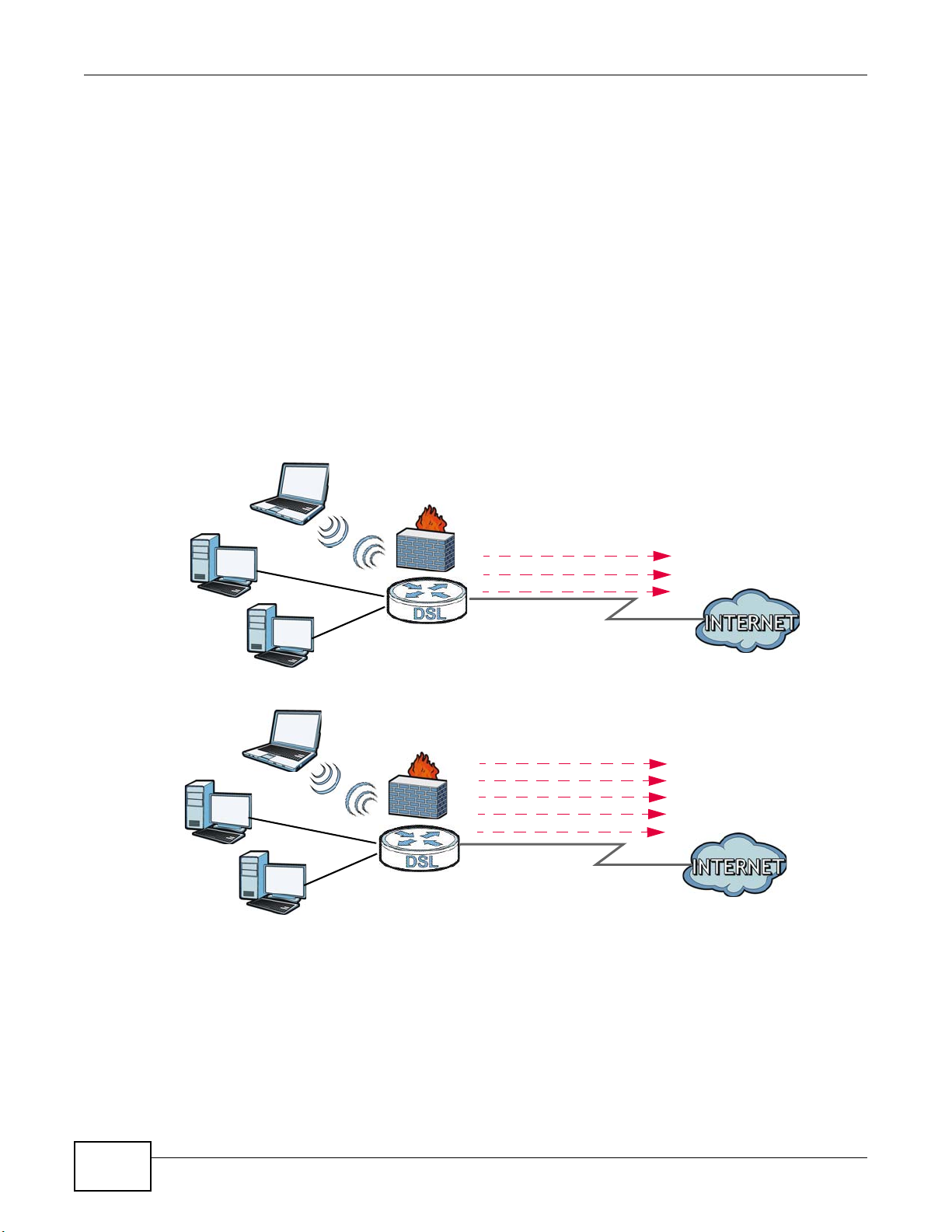
1.4.1 Internet Access
Your Device provides shared Internet access by connecting the DSL port to the DSL or MODEM
jack on a splitter or your telephone jack. You can have multiple WAN services over one ADSL or
VDSL. The Device cannot work in ADSL and VDSL mode at the same time.
Note: The ADSL and VDSL lines share the same WAN (layer-2) interfaces that you
configure in the Device. Refer to Section 6.2 on page 123 for the Network Setting
> Broadband screen.
Computers can connect to the Device’s LAN ports (or wirelessly).
Figure 1 Device’s Internet Access Application
18
SBG3300-N Series User’s Guide
You can also configure IP filtering on the Device for secure Internet access. When the IP filter is on,
B
A
all incoming traffic from the Internet to your network is blocked by default unless it is initiated from
your network. This means that probes from the outside to your network are not allowed, but you
can safely browse the Internet and download files.
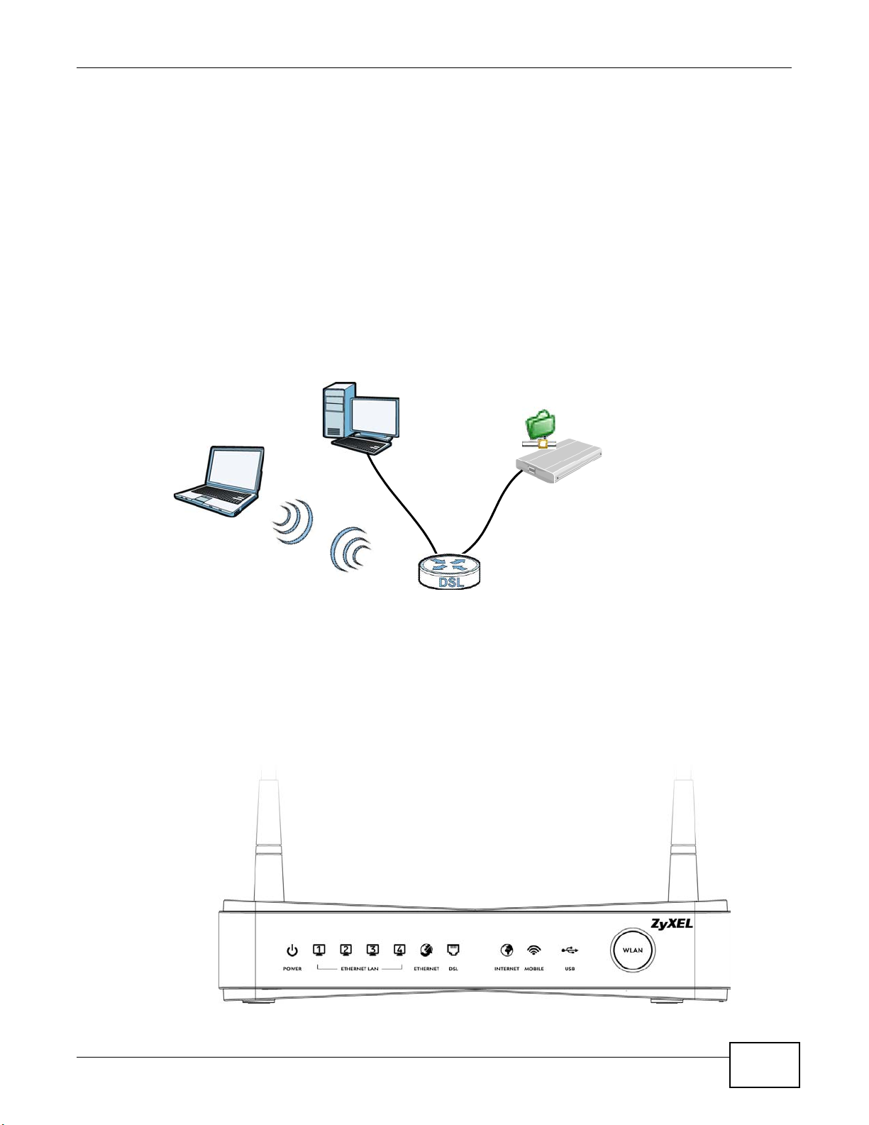
1.4.2 Device’s USB Support
The USB port of the Device is used for file-sharing.
File Sharing
Use the built-in USB 2.0 port to share files on a USB memory stick or a USB hard drive (B). You can
connect one USB hard drive to the Device at a time. Use FTP to access the files on the USB device.
Figure 2 USB File Sharing Application
Chapter 1 Introducing the Device
1.5 LEDs (Lights)
The following graphic displays the labels of the LEDs.
Figure 3 LEDs on the Device
SBG3300-N Series User’s Guide
19

Chapter 1 Introducing the Device
None of the LEDs are on if the Device is not receiving power.
Table 1 LED Descriptions
LED COLOR STATUS DESCRIPTION
POWER Green On The Device is receiving power and ready for use.
Red On The Device detected an error while self-testing, or there is a device
ETHERNET
LAN 1-4
ETHERNET Green On The Gigabit Ethernet connection is working.
DSL Green On The ADSL line is up.
INTERNET Green On The Device has an IP connection but no traffic.
MOBILE Green On The 3G WAN connection is working.
USB Green On The Device recognizes a USB connection.
WLAN/WPS Green On The wireless network is activated.
Green On The Device has a successful Ethernet connection with a device on the
Orange On The VDSL line is up.
Green
and
Orange
Blinking The Device is self-testing.
malfunction.
Off The Device is not receiving power.
Local Area Network (LAN).
Blinking The Device is sending or receiving data to/from the LAN.
Off The Device does not have an Ethernet connection with the LAN.
Blinking The Device is sending or receiving data to/from the Gigabit Ethernet
link.
Off There is no Gigabit Ethernet link.
Blinking The Device is initializing the ADSL line.
Off The ADSL line is down.
Blinking The Device is initializing the VDSL line.
Off The VDSL line is down.
Your device has a WAN IP address (either static or assigned by a DHCP
server), PPP negotiation was successfully completed (if used) and the
DSL connection is up.
Blinking The Device is sending or receiving IP traffic.
Off There is no Internet connection or the gateway is in bridged mode.
Blinking The Device is sending or receiving data to/from the 3G WAN connection.
Off There is no 3G WAN connection.
Blinking The Device is sending/receiving data to /from the USB device connected
to it.
Off The Device does not detect a USB connection.
Blinking The Device is communicating with other wireless clients.
Blinking The Device is setting up a WPS connection.
Off The wireless network is not activated.
20
SBG3300-N Series User’s Guide
1.6 The RESET Button
If you forget your password or cannot access the web configurator, you will need to use the RESET
button at the back of the device to reload the factory-default configuration file. This means that you
will lose all configurations that you had previously and the password will be reset to “1234”.
1 Make sure the POWER LED is on (not blinking).
2 To set the device back to the factory default settings, press the RESET button for ten seconds or
until the POWER LED begins to blink and then release it. When the POWER LED begins to blink,
the defaults have been restored and the device restarts.
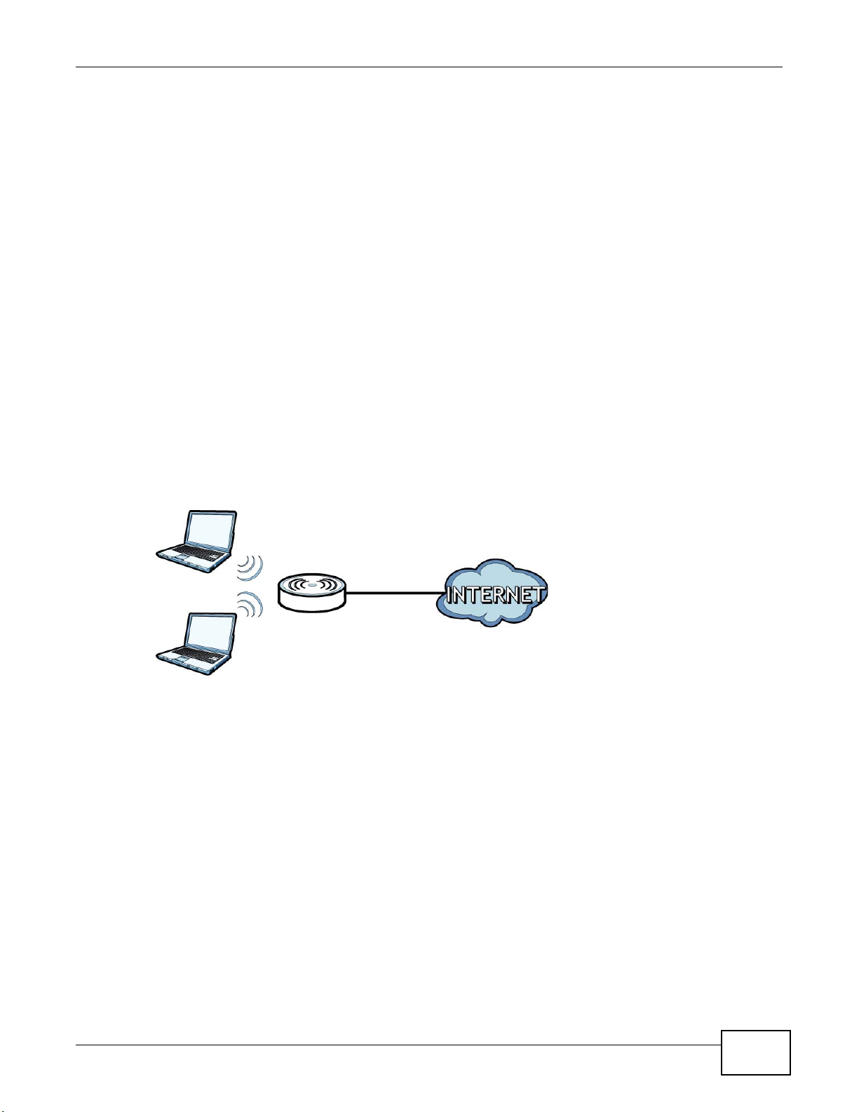
1.7 Wireless Access
The Device is a wireless Access Point (AP) for wireless clients, such as notebook computers or PDAs
and iPads. It allows them to connect to the Internet without having to rely on inconvenient Ethernet
cables.
Chapter 1 Introducing the Device
You can configure your wireless network in either the built-in Web Configurator.
Figure 4 Wireless Access Example
1.7.1 Using the WLAN Button
If the wireless network is turned off, press the WLAN button at the front of the Device for one
second. Once the WLAN LED turns green, the wireless network is active.
SBG3300-N Series User’s Guide
21

Chapter 1 Introducing the Device
22
SBG3300-N Series User’s Guide

2.1 Overview
The web configurator is an HTML-based management interface that allows easy device setup and
management via Internet browser. Use Internet Explorer 6.0 and later versions or Mozilla Firefox 3
and later versions or Safari 2.0 and later versions. The recommended screen resolution is 1024 by
768 pixels.
In order to use the web configurator you need to allow:
• Web browser pop-up windows from your device. Web pop-up blocking is enabled by default in
Windows XP SP (Service Pack) 2.
• JavaScript (enabled by default).
• Java permissions (enabled by default).
CHAPTER 2
The Web Configurator
See Appendix C on page 393 if you need to make sure these functions are allowed in Internet
Explorer.
2.1.1 Accessing the Web Configurator
1 Make sure your Device hardware is properly connected (refer to the Quick Start Guide).
2 Launch your web browser. If the Device does not automatically re-direct you to the login screen, go
to http://192.168.1.1.
3 A password screen displays. To access the administrative web configurator and manage the Device,
type the default username admin and password 1234 in the password screen and click Login. If
advanced account security is enabled (see Section 29.2 on page 325) the number of dots that
appears when you type the password changes randomly to prevent anyone watching the password
field from knowing the length of your password. If you have changed the password, enter your
password and click Login.
Figure 5 Password Screen
SBG3300-N Series User’s Guide 23
Chapter 2 The Web Configurator
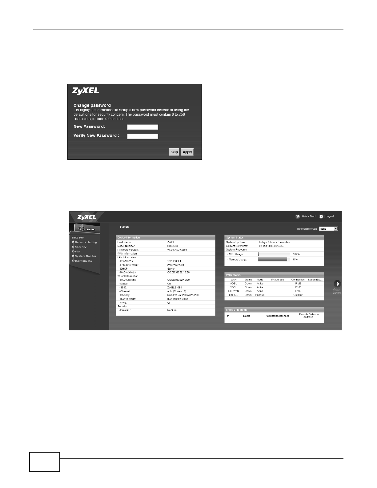
4 The following screen displays if you have not yet changed your password. It is strongly
recommended you change the default password. Enter a new password, retype it to confirm and
click Apply; alternatively click Skip to proceed to the main menu if you do not want to change the
password now.
Figure 6 Change Password Screen
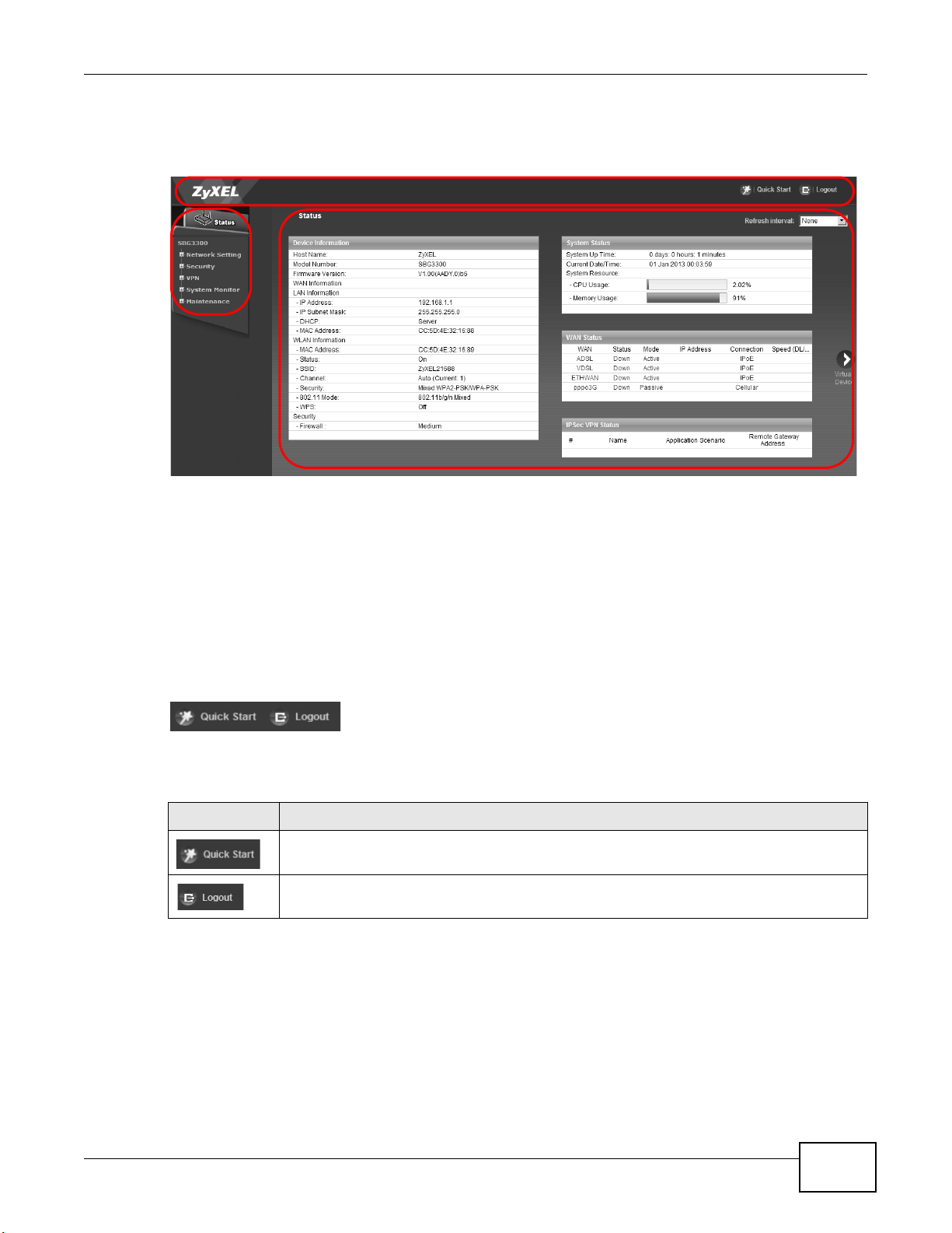
5 The Status page appears, where you can view the Device’s interface and system information.
6 Click the Quick Start Wizard button on top of the page to configure the Device’s time zone, basic
Internet access, and wireless settings. See Chapter 3 on page 31 for more information.
Figure 7 Status
24
SBG3300-N Series User’s Guide
2.2 Web Configurator Layout
B
C
A
Figure 8 Screen Layout
Chapter 2 The Web Configurator
As illustrated above, the main screen is divided into these parts:
• A - title bar
• B - main window
• C - navigation panel
2.2.1 Title Bar
The title bar provides some icons in the upper right corner.
The icons provide the following functions.
Table 2 Web Configurator Icons in the Title Bar
ICON DESCRIPTION
Quick Start: Click this icon to open screens where you can configure the Device’s time zone
Internet access, and wireless settings.
Logout: Click this icon to log out of the web configurator.
SBG3300-N Series User’s Guide
25
Chapter 2 The Web Configurator
2.2.2 Main Window
The main window displays information and configuration fields. It is discussed in the rest of this
document. See Chapter 5 on page 115 for more information about the Status screen.
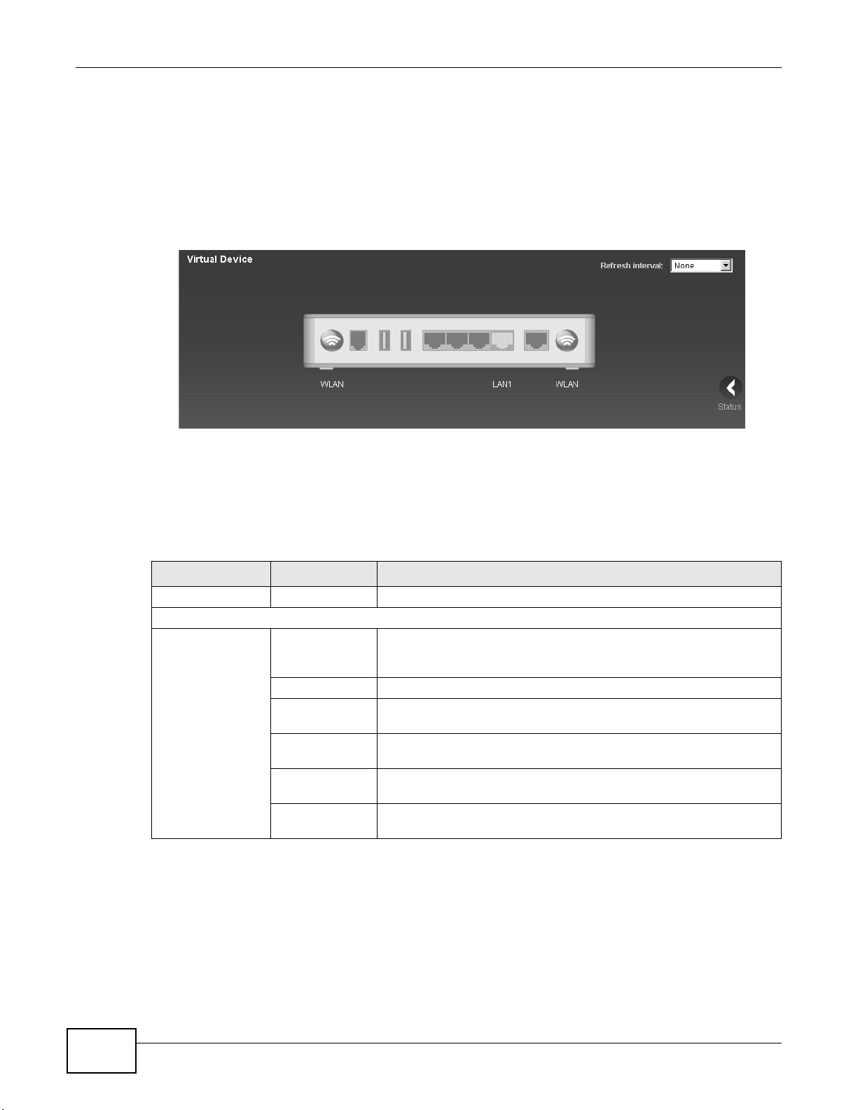
If you click Virtual Device on the System Info screen, a graphic shows the connection status of
the Device’s ports. The connected interfaces are in color and disconnected interfaces are gray.
Figure 9 Virtual Device
2.2.3 Navigation Panel
Use the menu items on the navigation panel to open screens to configure Device features. The
following tables describe each menu item.
Table 3 Navigation Panel Summary
LINK TAB FUNCTION
Status Click this to go to the main Web Configurator screen.
Network Setting
Broadband Broadband Use this screen to view and configure ISP parameters, WAN IP
3G WAN Use this screen to configure 3G WAN connection.
Add New 3G
Dongle
Advanced Use this screen to enable or disable PTM over ADSL, Annex M, and
802.1x Use this screen to view and configure the IEEE 802.1x settings on the
multi-WAN Use this screen to configure the multiple WAN load balance and
address assignment, and other advanced properties. You can also add
new WAN connections.
Use this screen to view or add a new 3G dongle.
DSL PhyR functions.
Device.
failover rules to distribute traffic among different interfaces.
26
SBG3300-N Series User’s Guide

Chapter 2 The Web Configurator
Table 3 Navigation Panel Summary (continued)
LINK TAB FUNCTION
Wireless General Use this screen to configure the wireless LAN settings and WLAN
authentication/security settings.
More AP Use this screen to configure multiple BSSs on the Device.
MAC
Authentication
WPS Use this screen to configure and view your WPS (Wi-Fi Protected
WMM Use this screen to enable or disable Wi-Fi MultiMedia (WMM).
Others Use this screen to configure advanced wireless settings.
Channel Status Use this screen to scan wireless LAN channel noises and view the
LAN LAN Setup Use this screen to configure LAN TCP/IP settings, and other advanced
Static DHCP Use this screen to assign specific IP addresses to individual MAC
UPnP Use this screen to turn UPnP and UPnP NAT-T on or off.
Additional
Subnet
5th Ethernet
Port
Routing Static Route Use this screen to view and set up static routes on the Device.
Policy
Forwarding
RIP
QoS General Use this screen to enable QoS and traffic prioritizing. You can also
Queue Setup Use this screen to configure QoS queues.
Class Setup Use this screen to define a classifier.
Policer Setup Use these screens to configure QoS policers.
Monitor Use this screen to view QoS packets statistics.
NAT Port Forwarding Use this screen to make your local servers visible to the outside
Applications Use this screen to configure servers behind the Device.
Port Triggering Use this screen to change your Device’s port triggering settings.
DMZ Use this screen to configure a default server which receives packets
ALG Use this screen to enable or disable NAT ALG and SIP ALG.
Address Mapping Use this screen to change your Device’s address mapping settings.
DNS DNS Entry Use this screen to view and configure DNS routes.
Dynamic DNS Use this screen to allow a static hostname alias for a dynamic IP
Interface
Group
USB Device Use this screen to enable file sharing via the Device.
Security
Use this screen to block or allow wireless traffic from wireless devices
of certain SSIDs and MAC addresses to the Device.
Setup) settings.
results.
properties.
addresses.
Use this screen to configure IP alias and public static IP.
Use this screen to configure the Ethernet WAN port as a LAN port.
Use this screen to configure policy routing on the Device.
Use this screen to set up RIP settings on the Device.
configure the QoS rules and actions.
world.
from ports that are not specified in the Port Forwarding screen.
address.
Use this screen to create a new interface group, which is a new LAN
bridge interface (subnet).
SBG3300-N Series User’s Guide
27

Chapter 2 The Web Configurator
Table 3 Navigation Panel Summary (continued)
LINK TAB FUNCTION
Firewall General Use this screen to configure the security level of your firewall.
MAC Filter Use this screen to block or allow traffic from devices of certain MAC
User Access
Control
Scheduler Rule Use this screen to configure the days and times when a configured
Certificates Local Certificates Use this screen to view a summary list of certificates and manage
VPN
IPSec VPN Setup Use this screen to display and manage the Device’s IPSec VPN rules
PPTP VPN Setup Use this screen to configure the PPTP VPN settings in the Device.
L2TP VPN Setup Use this screen to configure the Device’s L2TP VPN settings.
System Monitor
Log System Log Use this screen to view the status of events that occurred to the
Network Status WAN Use this screen to view the status of all network traffic going through
ARP Table Use this screen to view the ARP table. It displays the IP and MAC
Routing Table Use this screen to view the routing table.
IGMP Group
Status
xDSL Statistics Use this screen to view the Device’s xDSL traffic statistics.
Maintenance
User Account Use this screen to manage user accounts, which includes configuring
Remote MGMT Use this screen to enable specific traffic directions for network
Service Use this screen to add Internet services and configure firewall rules.
Access Control Use this screen to enable specific traffic directions for network
services.
DoS Use this screen to activate protection against Denial of Service (DoS)
attacks.
addresses to the Device.
Use this screen to block web sites with the specific URL.
restriction (such as User Access control) is enforced.
certificates and certification requests.
Trusted CA
Monitor Use this screen to display and manage active IPSec VPN connections.
Radius Use this screen to manage the list of RADIUS servers the Device can
Monitor Use this screen to view settings for PPTP clients.
Monitor Use this screen to view settings for L2TP clients.
Security Log Use this screen to view the login record of the Device. You can export
LAN Use this screen to view the status of all network traffic going through
Use this screen to view and manage the list of the trusted CAs.
(tunnels).
use in authenticating users.
Device. You can export or e-mail the logs.
or e-mail the logs.
the WAN port of the Device.
the LAN ports of the Device.
address of each DHCP connection.
Use this screen to view the status of all IGMP settings on the Device.
the username, password, retry times, file sharing, captive portal, and
customizing the login message.
services.
28
SBG3300-N Series User’s Guide

Chapter 2 The Web Configurator
Table 3 Navigation Panel Summary (continued)
LINK TAB FUNCTION
TR-069 Client Use this screen to configure the Device to be managed by an Auto
Configuration Server (ACS).
SNMP Use this screen to enable/disable and configure settings for SNMP.
Time Use this screen to change your Device’s time and date.
Email
Notification
Log Setting Use this screen to change your Device’s log settings.
Firmware
Upgrade
Configuration Use this screen to backup and restore your device’s configuration
Reboot Use this screen to reboot the Device without turning the power off.
Diagnostic Ping &
Traceroute &
Nslookup
802.1ag Use this screen to configure CFM (Connectivity Fault Management)
OAM Ping Use this screen to view information to help you identify problems with
Use this screen to configure up to two mail servers and sender
addresses on the Device.
Use this screen to upload firmware to your device.
(settings) or reset the factory default settings.
Use this screen to identify problems with the DSL connection. You can
use Ping, TraceRoute, or Nslookup to help you identify problems.
MD (maintenance domain) and MA (maintenance association),
perform connectivity tests and view test reports.
the DSL connection.
SBG3300-N Series User’s Guide
29

Chapter 2 The Web Configurator
30
SBG3300-N Series User’s Guide

3.1 Overview
Use the Quick Start screens to configure the Device’s time zone, basic Internet access, and
wireless settings.
Note: See the technical reference chapters (starting on page 113) for background
information on the features in this chapter.
3.2 Quick Start Setup
1 The Quick Start Wizard appears automatically after login. Or you can click the Click Start icon in
the top right corner of the web configurator to open the quick start screens. Select the time zone of
the Device’s location and click Next.
Figure 10 Time Zone
CHAPTER 3
Quick Start
SBG3300-N Series User’s Guide 31

Chapter 3 Quick Start
2 Select your current WAN interface to configure its settings.
Figure 11 WAN Interface Selection
3 Enter your Internet connection information in this screen. The screen and fields to enter may vary
depending on your current connection type. Click Next. Click Next.
Figure 12 Internet Connection
32
SBG3300-N Series User’s Guide

Chapter 3 Quick Start
4 Turn the wireless LAN on or off. If you keep it on, record the security settings so you can configure
your wireless clients to connect to the Device. Click Save.
Figure 13 Internet Connection
5 Your Device saves your settings and attempts to connect to the Internet.
SBG3300-N Series User’s Guide
33

Chapter 3 Quick Start
34
SBG3300-N Series User’s Guide
4.1 Overview
This chapter shows you how to use the Device’s various features.
• Setting Up an ADSL PPPoE Connection, see page 35
• Setting Up a Secure Wireless Network, see page 38
• Setting Up Multiple Wireless Groups, see page 44
• Configuring Static Route for Routing to Another Network, see page 47
• Configuring QoS Queue and Class Setup, see page 50
• Access the Device Using DDNS, see page 53
• Configuring the MAC Address Filter, see page 55
• Access Your Shared Files From a Computer, see page 56
• Certificate Configuration for VPN, see page 57
• Examples of Configuring IPSec VPN Rules, see page 60
• PPTP VPN Tutorial, see page 65
• L2TP VPN Tutorial, see page 85
CHAPTER 4
Tutorials
4.2 Setting Up an ADSL PPPoE Connection
This tutorial shows you how to set up your Internet connection using the Web Configurator.
If you connect to the Internet through an ADSL connection, use the information from your Internet
Service Provider (ISP) to configure the Device. Be sure to contact your service provider for any
information you need to configure the Broadband screens.
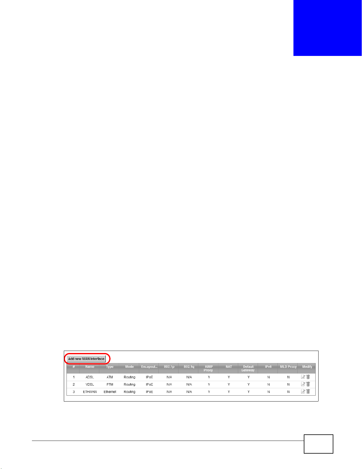
1 Click Network Setting > Broadband to open the following screen. Click Add New WAN
Interface.
2 In this example, the DSL connection has the following information.
SBG3300-N Series User’s Guide 35

Chapter 4 Tutorials
General
ATM PVC Configuration
Account Information
Name MyDSLConnection
Type ADSL
Connection Mode Routing
Encapsulation PPPoE
IPv6/IPv4 Mode IPv4
VPI/VCI 36/48
Encapsulation Mode LLC/SNAP-Bridging
Service Category UBR without PCR
PPP User Name 1234@DSL-Ex.com
PPP Password ABCDEF!
PPPoE Service Name MyDSL
Static IP Address 192.168.1.32
Others PPPoE Passthrough: Disabled
NAT: Enabled
IGMP Multicast Proxy: Enabled
Apply as Default Gateway: Enabled
3 Select the Active check box. Enter the General and ATM PVC Configuration settings as provided
above.
Set the Type to ADSL over ATM.
Choose the Encapsulation specified by your DSL service provider. For this example, the service
provider requires a username and password to establish Internet connection. Therefore, select
PPPoE as the WAN encapsulation type.
Set the IPv6/IPv4 Mode to IPv4 Only.
4 Enter the account information provided to you by your DSL service provider.
5 Configure this rule as your default Internet connection by selecting the Apply as Default Gateway
check box. Then select DNS as Static and enter the DNS server addresses provided to you, such as
192.168.5.2
(DNS server1)/192.168.5.1 (DNS server2).
6 Leave the rest of the fields to the default settings.
36
SBG3300-N Series User’s Guide

7 Click Apply to save your settings.
Chapter 4 Tutorials
SBG3300-N Series User’s Guide
37

Chapter 4 Tutorials
8 You should see a summary of your new DSL connection setup in the Broadband screen as follows.
Try to connect to a website to see if you have correctly set up your Internet connection. Be sure to
contact your service provider for any information you need to configure the WAN screens.
4.3 Setting Up a Secure Wireless Network
Thomas wants to set up a wireless network so that he can use his notebook to access the Internet.
In this wireless network, the Device serves as an access point (AP), and the notebook is the
wireless client. The wireless client can access the Internet through the AP.
Thomas has to configure the wireless network settings on the Device. Then he can set up a wireless
network using WPS (Section 4.3.2 on page 40) or manual configuration (Section 4.3.3 on page 43).
4.3.1 Configuring the Wireless Network Settings
This example uses the following parameters to set up a wireless network.
SSID Example
Security Mode WPA-PSK
Pre-Shared Key DoNotStealMyWirelessNetwork
802.11 Mode 802.11b/g/n Mixed
38
SBG3300-N Series User’s Guide

Chapter 4 Tutorials
1 Click Network Setting > Wireless to open the General screen. Select More Secure as the
security level and WPA-PSK as the security mode. Configure the screen using the provided
parameters (see page 38). Click Apply.
2 Go to the Wireless > Others screen and select 802.11b/g/n Mixed in the 802.11 Mode field.
Click Apply.
Thomas can now use the WPS feature to establish a wireless connection between his notebook and
the Device (see Section 4.3.2 on page 40). He can also use the notebook’s wireless client to search
for the Device (see Section 4.3.3 on page 43).
SBG3300-N Series User’s Guide
39

Chapter 4 Tutorials
4.3.2 Using WPS
This section shows you how to set up a wireless network using WPS. It uses the Device as the AP
and ZyXEL NWD210N as the wireless client which connects to the notebook.
Note: The wireless client must be a WPS-aware device (for example, a WPS USB adapter
or PCMCIA card).
There are two WPS methods to set up the wireless client settings:
• Push Button Configuration (PBC) - simply press a button. This is the easier of the two
methods.
• PIN Configuration - configure a Personal Identification Number (PIN) on the Device. A wireless
client must also use the same PIN in order to download the wireless network settings from the
Device.
Push Button Configuration (PBC)
1 Make sure that your Device is turned on and your notebook is within the cover range of the wireless
signal.
2 Make sure that you have installed the wireless client driver and utility in your notebook.
3 In the wireless client utility, go to the WPS setting page. Enable WPS and press the WPS button
(Start or WPS button).
4 Log into Device’s web configurator and go to the Network Setting > Wireless > WPS screen.
Enable the WPS function and click Apply. Then click the Connect button.
Note: You must enable the Wireless function in the Network Setting > Wireless >
General screen before you can enable the WPS function.
40
SBG3300-N Series User’s Guide

Chapter 4 Tutorials
Wireless Client
Device
SECURITY INFO
COMMUNICATION
WITHIN 2 MINUTES
Click “Connect”
Note: Your Device has a WPS button located on its front panel as well as a WPS button in
its configuration utility. Both buttons have exactly the same function: you can use
one or the other.
Note: It doesn’t matter which device’s WPS you enable first, but you must enable the
second device’s WPS within two minutes of enabling the first one.
The Device sends the proper configuration settings to the wireless client. This may take up to two
minutes. The wireless client is then able to communicate with the Device securely.
The following figure shows you an example of how to set up a wireless network and its security.
Example WPS Process: PBC Method
SBG3300-N Series User’s Guide
41

Chapter 4 Tutorials
PIN Configuration
When you use the PIN configuration method, you need to use both the Device’s web configurator
and the wireless client’s utility.
1 Launch your wireless client’s configuration utility. Go to the WPS settings and select the PIN method
to get a PIN number.
2 Log into Device’s web configurator and go to the Network Setting > Wireless > WPS screen.
Enable the WPS function and click Apply.
3 Enter the PIN number of the wireless client and click the Register button. Activate WPS function on
the wireless client utility screen within two minutes.
The Device authenticates the wireless client and sends the proper configuration settings to the
wireless client. This may take up to two minutes. The wireless client is then able to communicate
with the Device securely.
42
SBG3300-N Series User’s Guide

Chapter 4 Tutorials
Authentication by PIN
SECURITY INFO
WITHIN 2 MINUTES
Wireless Client
ZyXEL Device
COMMUNICATION
The following figure shows you how to set up a wireless network and its security on a Device and a
wireless client by using PIN method.
Example WPS Process: PIN Method
4.3.3 Without WPS
Use the wireless adapter’s utility installed on the notebook to search for the “Example” SSID. Then
enter the “DoNotStealMyWirelessNetwork” pre-shared key to establish an wireless Internet
connection.
Note: The Device supports IEEE 802.11b, IEEE 802.11g, and IEEE 802.11n wireless
clients. Make sure that your notebook or computer’s wireless adapter supports one
of these standards.
SBG3300-N Series User’s Guide
43

Chapter 4 Tutorials
Company
VIP
Guest
4.4 Setting Up Multiple Wireless Groups
Company A wants to create different wireless network groups for different types of users as shown
in the following figure. Each group has its own SSID and security mode.
• Employees in Company A will use a general Company wireless network group.
• Higher management level and important visitors will use the VIP group.
• Visiting guests will use the Guest group, which has a lower security mode.
Company A will use the following parameters to set up the wireless network groups.
COMPANY VIP GUEST
SSID Company VIP Guest
Security Level More Secure More Secure Basic
Security Mode WPA2-PSK WPA2-PSK Static WEP
Pre-Shared Key ForCompanyOnly ForVIPOnly Guest12345678
44
SBG3300-N Series User’s Guide

Chapter 4 Tutorials
1 Click Network Setting > Wireless to open the General screen. Use this screen to set up the
company’s general wireless network group. Configure the screen using the provided parameters
and click Apply.
2 Click Network Setting > Wireless > More AP to open the following screen. Click the Edit icon to
configure the second wireless network group.
SBG3300-N Series User’s Guide
45

Chapter 4 Tutorials
3 Configure the screen using the provided parameters and click Apply.
4 In the More AP screen, click the Edit icon to configure the third wireless network group.
46
SBG3300-N Series User’s Guide

5 Configure the screen using the provided parameters and click Apply.
Chapter 4 Tutorials
6 Check the status of VIP and Guest in the More AP screen. The yellow bulbs signify that the SSIDs
are active and ready for wireless access.
4.5 Configuring Static Route for Routing to Another Network
In order to extend your Intranet and control traffic flowing directions, you may connect a router to
the Device’s LAN. The router may be used to separate two department networks. This tutorial
shows how to configure a static routing rule for two network routings.
In the following figure, router R is connected to the Device’s LAN. R connects to two networks, N1
(192.168.1.x/24) and N2 (192.168.10.x/24). If you want to send traffic from computer A (in N1
SBG3300-N Series User’s Guide
47

Chapter 4 Tutorials
N2
B
N1
A
R
N2
B
N1
A
R
network) to computer B (in N2 network), the traffic is sent to the Device’s WAN default gateway by
default. In this case, B will never receive the traffic.
You need to specify a static routing rule on the Device to specify R as the router in charge of
forwarding traffic to N2. In this case, the Device routes traffic from A to R and then R routes the
traffic to B.
48
This tutorial uses the following example IP settings:
Table 4 IP Settings in this Tutorial
DEVICE / COMPUTER IP ADDRESS
The Device’s WAN 172.16.1.1
The Device’s LAN 192.168.1.1
IP Type IPv4
Use Interface ADSL/atm0
A 192.168.1.34
R’s N1 192.168.1.253
SBG3300-N Series User’s Guide

Table 4 IP Settings in this Tutorial
DEVICE / COMPUTER IP ADDRESS
R’s N2 192.168.10.2
B 192.168.10.33
To configure a static route to route traffic from N1 to N2:
1 Log into the Device’s Web Configurator in advanced mode.
2 Click Network Setting > Routing.
3 Click Add new static route in the Static Route screen.
4 Configure the Static Route Setup screen using the following settings:
Chapter 4 Tutorials
4a Select the Active check box. Enter the Route Name as R.
4b Set IP Type to IPv4.
4c Type 192.168.10.0 and subnet mask 255.255.255.0 for the destination, N2.
4d Select Enable in the Use Gateway IP Address field. Type 192.168.1.253 (R’s N1 address)
in the Gateway IP Address field.
4e Select ADSL/atm0 as the Use Interface.
4a Click OK.
Now B should be able to receive traffic from A. You may need to additionally configure B’s firewall
settings to allow specific traffic to pass through.
SBG3300-N Series User’s Guide
49

Chapter 4 Tutorials
10,000 kbps
DSL
Your computer
IP=192.168.1.23
A colleague’s computer
Other traffic: Automatic classifier
and/or
MAC=AA:FF:AA:FF:AA:FF
Email traffic: Highest priority
4.6 Configuring QoS Queue and Class Setup
This section contains tutorials on how you can configure the QoS screen.
Let’s say you are a team leader of a small sales branch office. You want to prioritize e-mail traffic
because your task includes sending urgent updates to clients at least twice every hour. You also
upload data files (such as logs and e-mail archives) to the FTP server throughout the day. Your
colleagues use the Internet for research, as well as chat applications for communicating with other
branch offices.
In the following figure, your Internet connection has an upstream transmission bandwidth of
10,000 kbps. For this example, you want to configure QoS so that e-mail traffic gets the highest
priority with at least 5,000 kbps. You can do the following:
• Configure a queue to assign the highest priority queue (1) to e-mail traffic going to the WAN
interface, so that e-mail traffic would not get delayed when there is network congestion.
• Note the IP address (192.168.1.23 for example) and/or MAC address (AA:FF:AA:FF:AA:FF for
example) of your computer and map it to queue 7.
Note: QoS is applied to traffic flowing out of the Device.
Traffic that does not match this class is assigned a priority queue based on the internal QoS
mapping table on the Device.
QoS Example
50
SBG3300-N Series User’s Guide

Chapter 4 Tutorials
1 Click Network Setting > QoS > General and select Enable. Set your WAN Managed Upstream
Bandwidth to 10,000 kbps (or leave this blank to have the Device automatically determine this
figure). Click Apply.
Tutorial: Advanced > QoS
2 Click Queue Setup > Add new Queue to create a new queue. In the screen that opens, check
Active and enter or select the following values:
• Name: E-mail
• Interface: WAN
• Priority: 1 (High)
• Weight: 8
• Rate Limit: 5,000 (kbps)
Tutorial: Advanced > QoS > Queue Setup
SBG3300-N Series User’s Guide
51

Chapter 4 Tutorials
3 Click Class Setup > Add new Classifier to create a new class. Check Active and follow the
settings as shown in the screen below.
Tutorial: Advanced > QoS > Class Setup
52
Class Name Give a class name to this traffic, such as E-mail in this example.
From
Interface
Ether Type Select IP to identify the traffic source by its IP address or MAC address.
IP Address Type the IP address of your computer - 192.168.1.23. Type the IP Subnet Mask if you
MAC Address Type the MAC address of your computer - AA:FF:AA:FF:AA:FF. Type the MAC Mask if you
To Queue
Index
This is the interface from which the traffic will be coming from. Select LAN1 for this
example.
know it.
know it.
Link this to an item in the Network Setting > QoS > Queue Setup screen, which is the E-
mail queue created in this example.
SBG3300-N Series User’s Guide

This maps e-mail traffic coming from port 25 to the highest priority, which you have created in the
w.x.y.z
a.b.c.d
http://zyxelrouter.dyndns.org
A
previous screen (see the IP Protocol field). This also maps your computer’s IP address and MAC
address to the E-mail queue (see the Source fields).
4 Verify that the queue setup works by checking Network Setting > QoS > Monitor. This shows
the bandwidth allotted to e-mail traffic compared to other network traffic.
4.7 Access the Device Using DDNS
If you connect your Device to the Internet and it uses a dynamic WAN IP address, it is inconvenient
for you to manage the device from the Internet. The Device’s WAN IP address changes dynamically.
Dynamic DNS (DDNS) allows you to access the Device using a domain name.
Chapter 4 Tutorials
To use this feature, you have to apply for DDNS service at www.dyndns.org.
This tutorial covers:
• Registering a DDNS Account on www.dyndns.org
• Configuring DDNS on Your Device
• Testing the DDNS Setting
Note: If you have a private WAN IP address, then you cannot use DDNS.
4.7.1 Registering a DDNS Account on www.dyndns.org
1 Open a browser and type http://www.dyndns.org.
2 Apply for a user account. This tutorial uses UserName1 and 12345 as the username and
password.
3 Log into www.dyndns.org using your account.
4 Add a new DDNS host name. This tutorial uses the following settings as an example.
•Hostname: zyxelrouter.dyndns.org
•Service Type: Host with IP address
• IP Address: Enter the WAN IP address that your Device is currently using. You can find the IP
address on the Device’s Web Configurator Status page.
Then you will need to configure the same account and host name on the Device later.
SBG3300-N Series User’s Guide
53

Chapter 4 Tutorials
4.7.2 Configuring DDNS on Your Device
Configure the following settings in the Network Setting > DNS > Dynamic DNS screen.
•Select Enable Dynamic DNS.
•Select www.DynDNS.com as the service provider.
•Type zyxelrouter.dyndns.org in the Host Name field.
• Enter the user name (UserName1) and password (12345).
Click Apply.
4.7.3 Testing the DDNS Setting
Now you should be able to access the Device from the Internet. To test this:
1 Open a web browser on the computer (using the IP address a.b.c.d) that is connected to the
Internet.
2 Type http://zyxelrouter.dyndns.org and press [Enter].
3 The Device’s login page should appear. You can then log into the Device and manage it.
54
SBG3300-N Series User’s Guide

4.8 Configuring the MAC Address Filter
Thomas
Josephine
Thomas noticed that his daughter Josephine spends too much time surfing the web and
downloading media files. He decided to prevent Josephine from accessing the Internet so that she
can concentrate on preparing for her final exams.
Josephine’s computer connects wirelessly to the Internet through the Device. Thomas decides to
use the Security > MAC Filter screen to grant wireless network access to his computer but not to
Josephine’s computer.
Chapter 4 Tutorials
1 Click Security > MAC Filter to open the MAC Filter screen. Select the Enable check box to
activate MAC filter function.
2 Select Allow. Then enter the host name and MAC address of Thomas’ computer in this screen. Click
Apply.
SBG3300-N Series User’s Guide
55

Chapter 4 Tutorials
Thomas can also grant access to the computers of other members of his family and friends.
However, Josephine and others not listed in this screen will no longer be able to access the Internet
through the Device.
4.9 Access Your Shared Files From a Computer
Here is how to enable the Samba feature on the Device and access a file storage device connected
to the Device’s USB port.
1 Log into the web configurator and go to the Maintenance > User Account screen. Click the Edit
icon on the account you are currently using. In this example, the account in use is admin. Click the
Edit icon next to it.
2 Set the File Sharing Service (SAMBA) feature to Enable to allow uses to access shared files in
USB storage. Enter mnt as the File Share Name. Click Apply.
56
SBG3300-N Series User’s Guide

Chapter 4 Tutorials
3 In this example, the FileZilla program is used to browse shared files. In FileZilla, enter the IP
address of the Device (the default is 192.168.1.1), your account’s user name and password and
port 21 and click Quickconnect. A screen asking for password authentication appears.
File Sharing via Windows Explore r
4 Once you log in the USB device displays in the mnt folder.
4.10 Certificate Configuration for VPN
You may generate a self-signed Certification Authority (CA) certificate using a third party tool or get
an official CA certificate from any trusted certificate agent. In this tutorial, a self-signed CA
certificate (cacert.pem) was created by using the openssl command in Fedora 10.
1 First, you need to import the CA certificate. Go to the Security > Certificates > Trusted CA
screen and click Import Certificate.
SBG3300-N Series User’s Guide
57

Chapter 4 Tutorials
2 Browse the directory in Fedora, or another system, which contains your CA certificate (e.g.,
cacert.pem), then click OK.
3 In the Security > Certificates > Local Certificates screen, click Create Certificate Request.
4 Enter your information as shown in the following screen and click Apply.
58
SBG3300-N Series User’s Guide

Chapter 4 Tutorials
5 The contents of the certificate display in the View Certificate screen. Copy the Signing Request
section and paste it to a file (for example, sbg.req) in Fedora, or another system, which contains
your original CA certificate.
6 In Fedora, issue the following openssl command to generate the host certificate for the Device:
openssl ca -config ./openssl.conf -policy policy_anything -out sbg.pem
-infiles sbg.req
7 Click the Load_Signed button in the View Certificate screen.
8 Cut the contents of sbg.pem (only the binary portion between BEGIN CERTIFICATE and END
CERTIFICATE). You can use "vi" or your favorite text editor to cut the portion, but do not use the
"cat" command.
9 Paste it to the indicated part of the Certificate section in the View Certificate screen. Click
Apply.
SBG3300-N Series User’s Guide
59
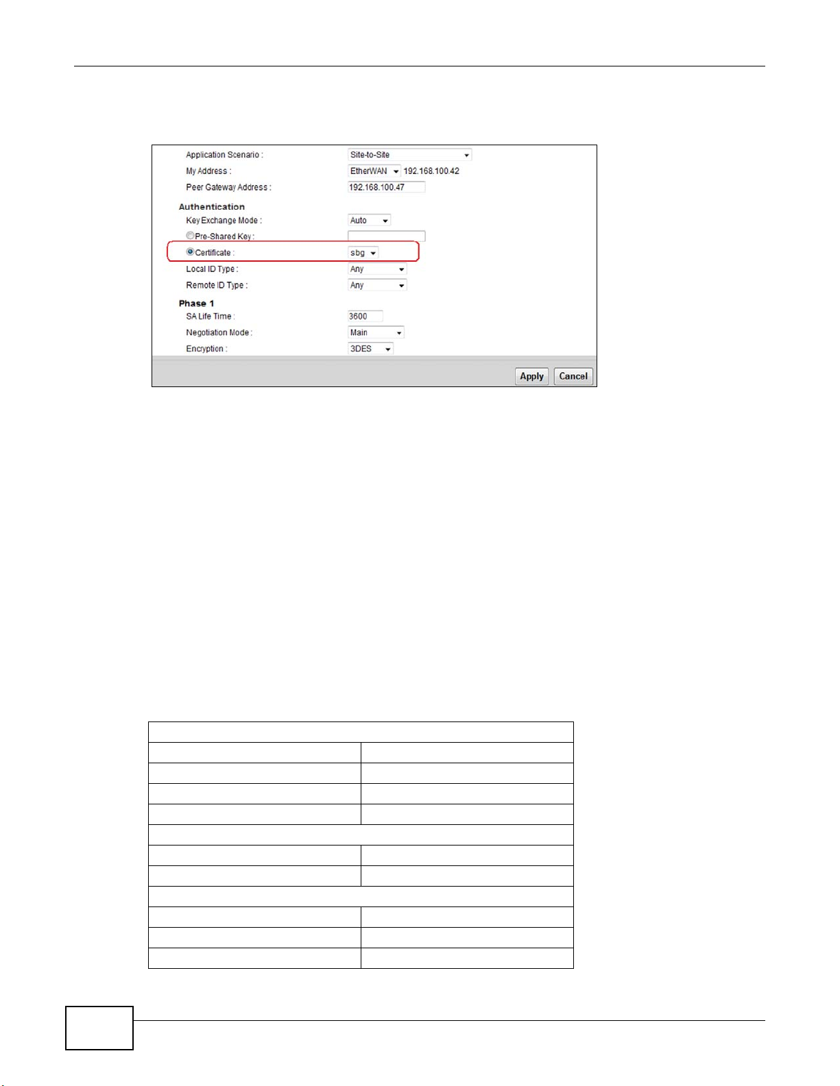
Chapter 4 Tutorials
10 Now you may configure VPN to use the new certificate for authentication in the VPN > IPSec VPN
> Monitor screen.
4.11 Examples of Configuring IPSec VPN Rules
The first two examples show how to configure Site-to-Site rules with pre-shared secrets. The first
example uses 3DES encryption and the second one uses AES128.
The third example shows how to configure a Site-to-Site with Dynamic Peer rule using pre-shared
secret keys.
Finally, the fourth example shows how to configure remote access using pre-shared secrets.
4.11.1 Example 1: Use 3DES Encryption
1 Click the Add New Entry button in the VPN > IPSec VPN > Setup screen and enter the following
parameters:
General
Connection Name vpn1
Application Scenario Site-to-Site
My Address ETHWAN
Peer Gateway Address 22.23.24.25
Authentication
Key Exchange Mode Auto
Pre-Shared Key 1234567890
Phase 1
SA Life Time 28800
Negotiation Mode Main
Encryption 3DES
60
SBG3300-N Series User’s Guide

Authentication SHA1
Key Group DH2
Phase 2
SA Life Time 3600
Tunnel Mode ESP
Encapsulation Tunnel
Encryption 3DES
Authentication SHA1
PFS DH2
Policy
Local IP Type Subnet
Local IP Address 192.168.1.0
Local Subnet Mask 255.255.255.0
Remote IP Type Subnet
Remote IP Address 172.23.9.0
Remote Subnet Mask 255.255.255.0
Chapter 4 Tutorials
SBG3300-N Series User’s Guide
61

Chapter 4 Tutorials
2 You can see the new IPSec VPN rule you’ve just created in the VPN > IPSec VPN > Monitor
screen. Select this rule and click Connect.
62
SBG3300-N Series User’s Guide

4.11.2 Example 2: Use AES128 Encryption
Here is another example of creating a Gateway-to-Gateway IPSec VPN rule with pre-shared secrets.
1 Click the Add New Entry button in the VPN > IPSec VPN > Setup screen.
2 Enter vpn2 as the Connection Name. Remove the existing encryption by clicking Remove icon or
Reset button. Then select AES128 and click the Add button in the Encryption fields of phase 1
and 2. Other parameters are the same as example 1’s.
Chapter 4 Tutorials
SBG3300-N Series User’s Guide
63

Chapter 4 Tutorials
3 You can see the new IPSec VPN rule you’ve just created in the VPN > IPSec VPN > Monitor
screen. Select this rule and click Connect.
4.11.3 Example 3: Configuring a Site-to-Site with Dynamic Peer Rule
Select Site-to-Site with Dynamic Peer in the Application Scenario field in the General
section. Other parameters are the same as example 1’s.
4.11.4 Example 4: Configuring a Remote Access Rule
Select Remote Access in the Application Scenario field in the General section. Other
parameters are the same as example 1’s.
64
SBG3300-N Series User’s Guide

Note: The Peer Gateway Address is not shown in the screen because it is an unknown
172.16.1.2
LAN Subnet #1: 192.168.1.0/24
LAN Subnet #2: 192.168.2.0/24
PPTP VPN IP Address Pool:
10.1.1.1 - 10.1.1.32
IP address to the remote access VPN client.
Note: The policy for the remote VPN client is not shown in the screen because it is an
unknown to the remote access VPN client.
4.12 PPTP VPN Tutorial
The example uses the following settings in setting up a basic PPTP VPN tunnel.
Figure 14 PPTP VPN Example
Chapter 4 Tutorials
• The Device has a static IP address of 172.16.1.2 for the DSL WAN interface.
• The remote user has a dynamic IP address and connects through the Internet.
• Use the default IP address pool to assign the remote users a point-to-point IP addresses from
10.1.1.1 to 10.1.1.32 for use in the PPTP VPN tunnel.
• The access group configuration allows the remote user to access only the LAN subnet #1
192.168.1.0/24.
4.12.1 Configuring PPTP VPN Setup (Server)
1.Go to the VPN > PPTP VPN > Setup screen and configure the following.
• Select the Enable checkbox.
•Set Access Group 1 to 192.168.1.0/255.255.255.0.
•Select DNS as User Defined and enter a DNS server address. The DNS server address in this
example is 8.8.8.8.
SBG3300-N Series User’s Guide
65

Chapter 4 Tutorials
• Click Apply.
4.12.2 Configuring PPTP VPN on Windows (Client)
The following sections cover how to configure PPTP in remote user computers using Windows 7,
Vista and XP. The example settings in these sections match the PPTP VPN configuration example in
Section 4.12 on page 65.
On Windows 7 and Vista
On Windows 7 and Vista, do the following to establish a PPTP VPN connection.
1 Click Start > Control Panel > Network and Internet > Network and Sharing Center >
Setup a connection or network > Connect to a workplace. Click Next.
66
SBG3300-N Series User’s Guide

2 Select No, create a new connection. Click Next.
3 Select Use my Internet connection (VPN).
Chapter 4 Tutorials
SBG3300-N Series User’s Guide
67

Chapter 4 Tutorials
4 Enter the domain name or WAN IP Address that you want to connect to (172.16.1.2 in this
example) and give this connection a name. Select Don't connect now; just set it up so I can
connect later. Click Next.
5 Click Create. Enter the user name and password later.
68
SBG3300-N Series User’s Guide

Chapter 4 Tutorials
On Vista
On Windows 7
6 Click Close. Do not connect yet.
7 Click the Network icon in your system tray, then click Network and Sharing Center on Vista or
Open Network and Sharing Center on Windows 7.
SBG3300-N Series User’s Guide
69

Chapter 4 Tutorials
8 On Vista, click Manage Network Connections.
9 On Windows 7, click Change adapter settings.
70
SBG3300-N Series User’s Guide

10 Double-click the new connection icon.
11 The connection screen appears. Click Properties.
Chapter 4 Tutorials
12 The Properties window appears. Click Security.
SBG3300-N Series User’s Guide
71

Chapter 4 Tutorials
13 (Vista) Select Advanced (custom settings) radio button and click Settings.
14 (Vista) Select Maximum strength encryption (disconnect if server declines) and the Allow
these protocols radio button. Select Microsoft CHAP Version 2 (MS-CHAP v2) and clear all of
the other check boxes. Click OK.
72
SBG3300-N Series User’s Guide

Chapter 4 Tutorials
15 (Vista) Click Networking. Select PPTP IPsec VPN as the Type of VPN. Then click OK.
16 (Windows 7) Select Point to Point Tunneling Protoco l (PPTP) as the Type of VPN. Select
Maximum strength encryption (disconnect if server declines) and the Allow these
protocols radio button. Select Microsoft CHAP Version 2 (MS-CHAP v2) and clear all of the
other check boxes. Do not click OK yet.
SBG3300-N Series User’s Guide
73

Chapter 4 Tutorials
17 In the Connect window, enter the username and password of your Device’s account. Click
Connect.
Note: The user account must have been configured in the Maintenance > User
Account screen. Refer to Chapter 29 on page 325.
18 A window appears while the username and password are verified. The connection is then
established.
19 (Vista) Click the Network icon in your system tray, then click the L2TP connection.
74
SBG3300-N Series User’s Guide

Chapter 4 Tutorials
20 The Network and Sharing Center windows appear. You can view the connection status or
disconnect the connection. Click View Status to open the connection status screen.
21 (Windows 7) Click the Network icon in your system tray, then right click the PPTP connection and
select Status to open the connection status screen.
SBG3300-N Series User’s Guide
75

Chapter 4 Tutorials
22 From the status screen, you can disconnect this connection. Or you can click Details to see the
connection details. The address 10.1.1.1 and 10.1.1.17 are addresses allocated from the PPTP IP
Address Pool you configured on the Device (10.1.1.1 - 10.1.1.32).
23 Access a server or other network resource on subnet 192.168.1.0 behind the Device to make sure
your access works.
On Windows XP
In Windows XP do the following to establish a PPTP VPN connection.
1 Click Start > Control Panel > Network Connections. Select Create a new connection .
2 Click Next in the welcome screen.
76
SBG3300-N Series User’s Guide

3 Select Connect to the network at my workplace and click Next.
4 Select Virtual Private Network connection and click Next.
Chapter 4 Tutorials
5 Type your Company Name, use PPTP to SBG3300 in this example, and click Next.
SBG3300-N Series User’s Guide
77

Chapter 4 Tutorials
6 Select Do not dial the initial connection and click Next.
7 Enter the domain name or WAN IP address that you want to connect to (172.16.1.2 in this
example). Click Next.
8 Click Finish.
78
SBG3300-N Series User’s Guide

Chapter 4 Tutorials
9 The connection screen appears. Click Properties > Security. Select Advanced (custom
settings) and click Settings.
10 Select Maximum strength encryption (disconnect if server declines) and the Allow these
protocols radio button. Select Microsoft CHAP Version 2 (MS-CHAP v2) and clear all of other
check boxes. Click OK.
SBG3300-N Series User’s Guide
79

Chapter 4 Tutorials
11 Click Networking. Select PPTP IPSec VPN as the Type of VPN. Click OK.
12 Enter the user name and password of your user account configured on the Device. Click Connect.
13 A window appears after the username and password are verified. The connection is then
established.
14 An icon displays in your system tray. Double-click it to open a status screen.
80
SBG3300-N Series User’s Guide

Chapter 4 Tutorials
15 From the status screen, you can disconnect this connection. Or you can click Details to see the
connection details. The address 10.1.1.1 and 10.1.1.17 are addresses allocated from the PPTP IP
Address Pool you configured on the Device (10.1.1.1 - 10.1.1.32).
16 Access a server or other network resource on subnet 192.168.1.0 behind the Device to make sure
your access works.
4.12.3 Configuring PPTP VPN on Android Devices (Client)
The following sections cover how to configure the built-in PPTP client in remote user’s Android
devices. Due to GUI difference among various Android devices, the figures may not exactly match
what your Android device displays. The example settings in these sections match the PPTP VPN
configuration example in Section 4.12 on page 65.
SBG3300-N Series User’s Guide
81

Chapter 4 Tutorials
1 On your Android device, select Home > Settings > Wireless and network > VPN settings.
2 Select Add VPN > Add PPTP VPN.
3 Fill out the following fields.
• VPN Name: Enter a name for your VPN configuration.
• Set VPN Server: This is the WAN IP address of the Device, in this example, 172.16.1.2
• Enable Encryption: checked.
• DNS search domains: not used.
82
SBG3300-N Series User’s Guide

Chapter 4 Tutorials
4 The new configuration will appear on the VPN settings screen. You can click the VPN name to
begin PPTP connection.
5 Enter the username and password of your user account configured on the Device.
Note: The user account must have been configured in the Maintenance > User
Account screen. Refer to Chapter 29 on page 325.
6 You can see Connected when the PPTP VPN connection has been established. Click the connection
name to get connection details. There you can also disconnect.
4.12.4 Configuring PPTP VPN in iOS Devices (Client)
The following sections cover how to configure the built-in PPTP client in iOS devices (iPhone, iPad,
iPod Touch, etc). Due to GUI difference among various iOS devices, the figures may not match what
your iOS device displays. The example settings in these sections match the PPTP VPN configuration
example in Section 4.12 on page 65.
SBG3300-N Series User’s Guide
83

Chapter 4 Tutorials
1 On your iOS device, select Home > Settings > General > Network.
2 Select VPN > Add VPN Configuration….
3 Select the PPTP tab. Enter the following fields.
• Description: Enter a name for your VPN configuration.
• Server: This is the WAN IP address of the Device, in this example, 172.16.1.2.
• Account: This is the user account created on Device for accessing the network via VPN.
• RSA SecurID: Not used in this configuration.
• Password: This is the password for account.
• Secret: This is your pre-shared key for your VPN connection, in this example, 1234567890.
84
SBG3300-N Series User’s Guide

Chapter 4 Tutorials
• Send All Traffic: This example uses the route-all configuration (ON).
4 Save the configuration.
5 The saved configuration will appear on the VPN screen. Select it and then slide the VPN bar to the
ON position. Your iOS device will begin PPTP connection.
4.13 L2TP VPN Tutorial
This section illustrates how to set up a basic L2TP VPN tunnel between the Device and a remote
client.
SBG3300-N Series User’s Guide
85

Chapter 4 Tutorials
172.16.1.2
LAN Subnet #1: 192.168.1.0/24
LAN Subnet #2: 192.168.2.0/24
L2TP VPN IP Address Pool:
10.2.1.1 - 10.2.1.32
The example uses the following settings in setting up a basic L2TP VPN tunnel.
Figure 15 L2TP VPN Example
• The Device has a static IP address of 172.16.1.2 for the DSL WAN interface.
• The remote user has a dynamic IP address and connects through the Internet.
• Use the default IP address pool to assign the remote users a point-to-point IP addresses from
10.2.1.1 to 10.2.1.32 for use in the L2TP VPN tunnel.
• The access group configuration allows the remote L2TP user to access only the LAN subnet
192.168.2.0/24.
4.13.1 Configuring the Default_L2TPVPN IPSec VPN Rule (Server)
1 Go to the VPN > IPSec VPN screen which lists the VPN rules. Click the Edit icon of the
Default_L2TPVPN entry.
2 Select the Enable checkbox.
3 Select Pre-Shared Key and configure a password. This example uses 1234567890.
86
SBG3300-N Series User’s Guide

4 Click Apply.
4.13.2 Configuring the L2TP VPN Setup (Server)
Chapter 4 Tutorials
1 Go to the VPN > L2TP VPN > Setup screen and configure the following:
• Select the Enable checkbox.
•Set Access Group 1 to 192.168.2.0/255.255.255.0.
•Select DNS as User Defined and enter a DNS server address. The DNS server address in this
example is 8.8.8.8.
• Click Apply.
SBG3300-N Series User’s Guide
87

Chapter 4 Tutorials
4.13.3 Configuring L2TP VPN in Windows (Client)
The following sections cover how to configure L2TP on the remote user computers using Windows 7,
Vista and XP. The example settings in these sections match the L2TP VPN configuration example in
Section on page 86.
4.13.3.1 Enabling IPSec Service in Windows
By default, a Windows computer should have IPSec service enabled. However, before you configure
the client, it is suggested to make sure the computer is running the Microsoft IPSec service.
For Windows Vista and Windows 7
1 Click the Start button and enter “services” in the text box. Then click Services under the
Programs window.
88
SBG3300-N Series User’s Guide

Chapter 4 Tutorials
2 In the Services window, scroll down to find IPsec Policy Agent. Make sure the status is Started.
If not, click Start the service in the left panel.
For Windows XP
1 Click Start > Run and enter "services.msc" in the text box. Click OK.
SBG3300-N Series User’s Guide
89

Chapter 4 Tutorials
2 In the Services window, scroll down to find IPSEC Services. Make sure the status is Started. If
not, click Start the service in the left panel.
4.13.4 Configuring L2TP VPN on Windows 7 and Vista
In Windows 7 and Vista do the following to establish an L2TP VPN connection.
1 Click Start > Control Panel > Network and Internet.
90
SBG3300-N Series User’s Guide

Chapter 4 Tutorials
2 Click Network and Sharing Center > Setup a connection or network > Connect to a
workplace. Click Next.
3 Select No, create a new connection. Click Next.
SBG3300-N Series User’s Guide
91

Chapter 4 Tutorials
4 Select Use my Internet connection (VPN).
5 Enter the domain name or WAN IP Address that you want to connect to (172.16.1.2 in this
example) and give this connection a name. Select Don't connect now; just set it up so I can
connect later. Click Next.
92
SBG3300-N Series User’s Guide

6 Click Create. Enter the user name and password later.
7 Click Close. Do not connect yet.
Chapter 4 Tutorials
SBG3300-N Series User’s Guide
93

Chapter 4 Tutorials
On Vista
On Windows 7
8 Click the Network icon in your system tray, then click Network and Sharing Center on Vista or
Open Network and Sharing Center on Windows 7.
9 On Vista, click Manage Network Connections.
94
SBG3300-N Series User’s Guide

10 On Windows 7, click Change adapter settings.
11 Double-click the new connection icon.
Chapter 4 Tutorials
SBG3300-N Series User’s Guide
95

Chapter 4 Tutorials
12 The connection screen appears. Click Properties.
13 The Properties window appears. Click Security.
14 (Windows 7) Select Layer 2 Tunneling Protocol with IPsec (L2TP/IPsec) as the Type of VPN.
Select the Optional encryption (connect even if no encryption) and the Allow these
protocols radio button. Select Microsoft CHAP Version 2 (MS-CHAP v2) and clear all of other
check boxes. Do not click OK yet.
96
SBG3300-N Series User’s Guide

Chapter 4 Tutorials
15 (Windows 7) Click Advanced settings. Select the Use preshared key for authentication radio
button. Enter the pre-shared key used in the IPSec configuration that the Device is using for
Default_L2TPVPN IPSec VPN rule. In this example, enter 1234567890. Click OK to return to the
Connect window.
16 (Vista) Select Advanced (custom settings) radio button and click Settings.
SBG3300-N Series User’s Guide
97

Chapter 4 Tutorials
17 (Vista) Select Optional encryption (connect even if no encryption) and the Allow these
protocols radio button. Select Microsoft CHAP Version 2 (MS-CHAP v2) and clear all of other
check boxes. Click OK.
18 (Vista) Click Networking. Select L2TP IPsec VPN as the Type of VPN. Then click IPsec
Settings.
98
SBG3300-N Series User’s Guide

Chapter 4 Tutorials
19 (Vista) The IPsec Settings screen appears. Select the Use preshared key for authentication
radio button. Enter the pre-shared key used in the IPSec configuration that the Device is using for
the Default_L2TPVPN IPSec VPN rule, in this example, enter 1234567890. Click OK.
20 Enter the username and password of your user account configured on the Device. Click Connect.
Note: The user account must have been configured in the Maintenance > User
Account screen. Refer to Chapter 29 on page 325.
21 A window appears while the username and password are verified. The connection is then
established.
SBG3300-N Series User’s Guide
99

Chapter 4 Tutorials
22 (Windows 7) Click the Network icon in your system tray, then right click the L2TP connection and
select Status to open the connection status screen.
23 From the status screen, you can disconnect this connection. Or you can click Details to see the
connection details. The address 10.2.1.2 and 10.2.1.12 are addresses allocated from the L2TP IP
Address Pool you configured on the Device (10.2.1.1 - 10.2.1.32).
100
SBG3300-N Series User’s Guide
 Loading...