

Page 1

SAM1316-22
SHDSL.bis module of IES-1000
Default Login Details
IP Address http://192.168.1.1
User Name admin
Password 1234
Firmware Version 3.53
Edition 1, 4/2010
www.zyxel.com
www.zyxel.com
Copyright © 2010
ZyXEL Communications Corporation
Page 2

Page 3
About This User's Guide
Intended Audience
This manual is intended for people who want to install, connect, or configure the
SAM1316-22.
Related Documentation
• IES-1000 User’s Guide
See this User’s Guide for more on the chassis in which you install the SAM1316-
22.
• Support Disc
Refer to the included CD for support documents.
Documentation Feedback
Send your comments, questions or suggestions to: techwriters@zyxel.com.tw
Thank you!
The Technical Writing Team, ZyXEL Communications Corp.,
6 Innovation Road II, Science-Based Industrial Park, Hsinchu, 30099, Taiwan.
Need More Help?
More help is available at www.zyx el.com.
• Download Library
Search for the latest product updates and documentation from this link. Read
the Tech Doc Overview to find out how to efficiently use the documentation in
order to better understand how to use your product.
SAM1316-22 User’s Guide
3
Page 4

• Knowledge Base
If you have a specific question about your product, the answer may be here.
This is a collection of answers to previously asked questions about ZyXEL
products.
•Forum
This contains discussions on ZyXEL prod ucts. Learn from others who use ZyXEL
products and share your experiences as well.
Customer Support
Should problems arise that cannot be solved by the methods listed above, you
should conta ct your vendor. If you cannot contact your vendor, then contact a
ZyXEL office for the region in which you bought the device.
See http://www.zyxel.com/web/contact_us.php for contact information. Please
have the following informatio n ready when you contact an office.
• Product model and serial number.
•Warranty Information.
• Date that you received your device.
• Brief description of the problem and the steps you took to solve it.
4
SAM1316-22 User’s Guide
Page 5

Document Conventions
Note: Notes tell you other important information (for example, other things you may
need to configure or helpful tips) or recommendations.
Syntax Conventions
• The SAM1316-22 may be referred to as the “SAM1316-22”, the “device”, the
“system”, the “switch”, or the “product” in this User’s Guide.
• Product labels, screen names, field labels and field choices are all in bold font.
• A key stroke is denoted by square brackets and uppercase text, for example,
[ENTER] means the “enter” or “ret urn” key on your keyboard.
• “Enter” means for you to type one or more characters and then press the
[ENTER] key. “Select” or “choose” means for you to use one of the predefined
choices.
• Mouse action sequences are denoted using a comma. For example, “In
Windows, click Start, Programs, Acrobat Reader” means first click the Start
button, then move your mouse pointer to Programs and then click Acrobat
Reader.
• Units of measurement may denote the “metric” value or the “scientific” value.
For example, “k” for kilo may denote “1000” or “1024”, “M” for mega may
denote “1000000” or “1048576” and so on.
• “e.g.,” is a shorthand for “for instance”, and “i.e.,” means “that is” or “in other
words”.
Icons Used in Figures
Figures in this User’s Guide use the following generic icons. The SAM1316-22 icon
is not an exact representation of your SAM1316-22.
Graphics in this book may differ slightly from the product due to differences in
operating systems, operating system versions, or if you installed updated
firmware/software fo r y our dev ice. Ev ery effort has been made to ensur e that the
information in this manual is accurate.
SAM1316-22 User’s Guide
5
Page 6
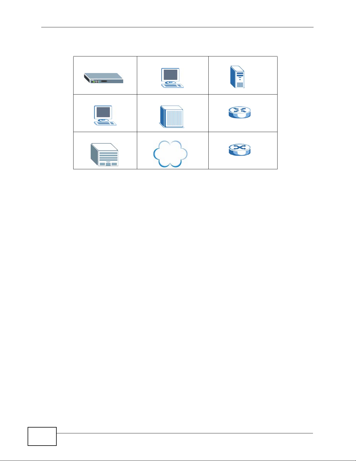
SAM1316-22 Computer Server
Computer DSLAM Gateway
Central Office/ ISP Internet Hub/Switch
Firmware Naming Conventions
A firmware version includes the model code and release number as shown in the
following example.
Firmware Version: V3.53 (BVE.0)
"BVE" is the model code.
"0" is this firmware's release number. This varies as new firmware is released. Your
firmware's release number may not match what is displayed in this User's Guide.
6
SAM1316-22 User’s Guide
Page 7

Safety Warnings
• Do NOT use this product near water, for example, in a wet basement or near a swimming
pool.
• Do NOT expose your device to dampness, dust or corrosive liquids.
• Do NOT store things on the device.
• Do NOT install, use, or service this device during a thunderstorm. There is a remote risk
of electric shock from lightning.
• Connect ONLY suitable accessories to the device.
• Do NOT open the device or unit. Opening or removing covers can expose you to
dangerous high voltage points or other risks. ONLY qualified service personnel should
service or disassemble this device. Please contact your vendor for further information.
• Make sure to connect the cables to the correct ports.
• Place connecting cables carefully so that no one will step on them or stumble over them.
• Always disconnect all cables from this device before servicing or disassembling.
• Do not use the device outside, and make sure all the connections are indoors. There is a
remote risk of electric shock from lightning.
• CAUTION: RISK OF EXPLOSION IF BATTERY (on the motherboard) IS REPLACED BY AN
INCORRECT TYPE. DISPOSE OF USED BATTERIES ACCORDING TO THE INSTRUCTIONS.
Dispose them at the applicable collection point for the recycling of electrical and
electronic equipment. For detailed information about recycling of this product, please
contact your local city office, your household waste disposal service or the store where
you purchased the product.
• Do NOT obstruct the device ventilation slots, as insufficient airflow may harm your
device.
• Use only No. 26 AWG (American Wire Gauge) or larger telecommunication line cord.
Your product is marked with this symbol, which is known as the WEEE mark. WEEE
stands for Waste Electronics and Electrical Equipment. It means that used electrical
and electronic products should not be mixed with general waste. Used electrical and
electronic equipment should be treated separately.
SAM1316-22 User’s Guide
7
Page 8

8
SAM1316-22 User’s Guide
Page 9

Contents Overview
User’s Guide ........................................................................................................ ...................27
Getting to Know the SAM1316-22 ............................................................................................. 29
Installing and Removing the SAM1316-22 ................................................................................ 33
Front Panel ................................................................................................................................ 37
Technical Reference ..............................................................................................................43
Introducing the Web Configurator .............................................................................................. 45
Initial Configuration .................................................................................................................... 53
Home and Port Statistics Screens ............................................................................................. 59
System Information ......... .... ... ............................................. ... .... ... ... ... ... .... ... ... ... ....................... 71
General Setup ............................................. .... ... ... ... .... .............................................................75
User Account ...................................................................................................... .... ... ... .............77
Switch Setup ............. ... ... .... ... ............................................. ... .... ... ... ... ... .................................... 81
IP Setup .......................... .... ... ... ... .... ... ... ... ............................................. .... ... ... ... .... ... ................ 87
ENET Port Setup ....................................................................................................................... 89
xDSL Port Setup ........................................................................................................................ 91
xDSL Profiles Setup ................................................................................................................ 107
xDSL Line Data ....................................................................................................................... 123
G.bond ..................................................................................................................................... 129
VLAN ....................................................................................................................................... 133
IGMP .......................................................................................................................................141
Static Multicast ......................................................................................................................... 153
Multicast VLAN ........................................................................................................................ 155
Filtering ..................................... .................................................... ........................................... 161
MAC Filter ................................................................................................................................ 165
Spanning Tree Protocol .. .... ... ... ... ............................................................................................ 167
Port Authentication ............................. ... .................................................................................. 175
Port Security .......................................................... ............................................. .... ... ..............181
DHCP Relay ............................................................................................................................183
DHCP Snoop ........................................................................................................................... 189
2684 Routed Mode ...... ... .... ... ... ... .... ... ... ... ... .... ................................................ ... .... ... ... ... ... ..... 193
PPPoA to PPPoE .................................................................................................................... 203
DSCP .............................. .................... ................... .................... ................... ........................... 209
TLS PVC ................... ... ............................................. .... ... ... ... .... ... ........................................... 213
ACL ..................................... ................... ................... .................... ................... ........................ 217
Downstream Broadcast ...........................................................................................................225
Syslog ....................................... .................................................... ........................................... 227
Access Control ........................................................................................................................ 229
SAM1316-22 User’s Guide
9
Page 10

PPPoE Intermediate Agent ...................................................................................................... 237
Maximum MTU Size ................................................................................................................ 241
PVC Upstream Limit ........................................................ ... ... .... ... ... ........................................ 243
OUI Filter ................................................................................................................................. 247
Static Routing ..........................................................................................................................249
Alarm .......................................................................................................................................251
Maintenance ............................................................................................................................ 261
Diagnostic .................................... ....................................................... ..................................... 265
MAC Table ............................................................................................................................... 267
ARP Table ........................................ ... ... ... ... .... ... ............................................. ... .... ... ..............271
Commands .............................................................................................................................. 273
Command Examples ...............................................................................................................297
Alarm Commands .................................................................................................................... 303
DHCP Commands ....................................................................................................................311
IEEE 802.1Q Tagged VLAN Commands ............................................................ .....................323
MAC Commands .....................................................................................................................333
IGMP Commands .................................................................................................................... 339
PPPoE Intermediate Agent Commands .................................................................................. 357
OUI Filter Commands .............................................................................................................. 361
Packet Filter Commands .........................................................................................................365
IP Commands .............................. .... ... ... ... ... .... ... ... ... ...............................................................369
Firmware and Configuration File Maintenance ........................................................................375
SNMP ...................................................................................................................................... 381
DSL Commands ...................................................................................................................... 385
Virtual Channel Management .................................................................................................. 401
ACL Commands ...................................................................................................................... 429
Troubleshooting ..................................................... .................................................................. 435
Specifications ......................................................... .................... ................... ...........................445
10
SAM1316-22 User’s Guide
Page 11

Table of Contents
About This User's Guide..........................................................................................................3
Document Conventions............................................................................................................5
Safety Warnings ........................................................................................................................7
Contents Overview ...................................................................................................................9
Table of Contents....................................................................................................................11
Part I: User’s Guide................................................................................ 27
Chapter 1
Getting to Know the SAM1316-22..........................................................................................29
1.1 Overview ............. ............................................. ... .... ... ... ... .... ................................................ 29
1.2 Applications ........................ ... .... ... ... ... ... .............................................. ... ... ... .... ... ... .............29
1.2.1 MTU Application ........................................ ................................................................. 29
1.2.2 Curbside Application .................................................................................................. 30
Chapter 2
Installing and Removing the SAM1316-22............................................................................33
2.1 Overview ............. ............................................. ... .... ... ... ... .... ................................................ 33
2.2 Installing the SAM1316-22 in the IES-1000 ......................................................................... 33
2.3 Removing the SAM1316-22 from the IES-1000 ........................ ... ... .... ... ... ... ....................... 34
Chapter 3
Front Panel..............................................................................................................................37
3.1 LEDs ......................... .... ............................................. ... ... .... ................................................ 37
3.2 Front Panel Ports ................ ... .... ............................................. ... ... ... .... ... ... ... .... ... ... .............38
3.2.1 Console Port ....... ... ... ... .... ... ... ... ... .............................................. ... ... ... .... ... ... ... ... .... ... 38
3.2.2 LAN (Ethernet) Ports .................................................................................................. 38
3.2.3 USER Ports .................................. .... ... ... ... .... ... ............................................. ... ... .... ... 39
Part II: Technical Reference.................................................................. 43
Chapter 4
Introducing the Web Configurator ........................................................................................45
SAM1316-22 User’s Guide
11
Page 12

4.1 Overview ............. ............................................. ... .... ... ... ... .... ................................................ 45
4.2 Screen Privilege Levels ....................................................... ... ............................................. 45
4.3 Accessing the Web Configurator .........................................................................................45
4.4 Navigation Panel ................................................................................................................. 47
4.5 Changing Your Password ... ... .... ... ... ... ... .... ... ... ... .... ... ................................................ ... .... ... 50
4.6 Saving Your Configuration ...................................................................................................51
4.7 Logging Out of the Web Configurator ..................................... ............................................. 51
Chapter 5
Initial Configuration................................................................................................................53
5.1 Overview ............. ............................................. ... .... ... ... ... .... ................................................ 53
5.2 Initial Configuration ....................... ... ... ... .... ... ... ............................................. .... ... ... ... ..........53
Chapter 6
Home and Port Statistics Screens.........................................................................................59
6.1 Home Screen ................ ............................................. ... ... .... ... ... ... ....................................... 59
6.1.1 Ethernet Port Statistics Screen .............................. .... ... ... ... ... .... ... ... ... .... ... ................ 61
6.1.2 DSL Port Statistics Screen ............................... ... ... .... ................................................ 64
6.1.3 RMON Statistics Screen ............................................................................................. 66
6.1.4 RMON History Screen ................................................................................................ 68
6.1.5 RMON History Detail Screen ..................................................................................... 69
Chapter 7
System Information ................................................................................................................71
Chapter 8
General Setup..........................................................................................................................75
Chapter 9
User Account...........................................................................................................................77
9.1 User Account Screen ................. ... ... ... ... .... ................................................ ... .... ................... 77
9.2 Authentication Screen ........................................ .... ... ... ... .... ................................................ 78
Chapter 10
Switch Setup ...........................................................................................................................81
10.1 GARP Timer Setup ............................................................................................................ 81
10.2 Switch Modes .................................................................................................................... 81
10.2.1 Standalone Switch Mode .......................................................................................... 81
10.2.2 Port Isolation with Standalone Switch Mode Example ............................................. 82
10.2.3 Daisychain Switch Mode .......................................................................................... 82
10.2.4 Port Isolation with Daisychain Switch Mode Example .............................................. 83
10.3 Switch Setup Screen ......................................................................................................... 84
Chapter 11
IP Setup....................................................................................................................................87
12
SAM1316-22 User’s Guide
Page 13

Chapter 12
ENET Port Setup.....................................................................................................................89
Chapter 13
xDSL Port Setup......................................................................................................................91
13.1 DSL Profiles ....................................................................................................................... 91
13.2 Alarm Profiles .................................................................................................................... 91
13.3 Downstream and Upstream ............................................................................................... 91
13.4 EFM and ATM Modes ........................................................................................................ 92
13.5 Default Settings ................................................................................................................. 92
13.6 xDSL Port Setup Screen ................................................................................................... 92
13.6.1 xDSL Port Setting Screen ........................................................................................ 95
13.7 Virtual Channels ................................................................................................................ 97
13.7.1 Super Channel ......................................................................................................... 97
13.7.2 LLC ...........................................................................................................................98
13.7.3 VC Mux .................................................................................................................... 98
13.7.4 Virtual Channel Profile .............................................................................................98
13.8 VC Setup Screen ............................................................................................................... 98
13.9 Priority-based PVCs ........................................................................................................ 102
13.10 PPVC Setup Screen ......................................................................................................103
13.10.1 PPVC Setup Members Screen ............................................................................. 104
Chapter 14
xDSL Profiles Setup..............................................................................................................107
14.1 Configured Versus Actual SHDSL Rates .........................................................................107
14.2 N-wire Mode ....................................................................................................................107
14.3 Port Profile Screen .......................................................................................................... 108
14.4 ATM QoS ..........................................................................................................................110
14.5 Traffic Shaping ..................................................................................................................110
14.5.1 ATM Traffic Classes ................................................................................................110
14.5.2 Traffic Parameters ...................................................................................................111
14.6 Upstream Policing ............................................................................................................113
14.7 VC Profile Screen .............................................................................................................11 4
14.8 Alarm Profile Screen .........................................................................................................116
14.8.1 Alarm Profile Map Screen .......................................................................................117
14.9 IGMP Filtering ...................................................................................................................11 8
14.10 IGMP Filter Profile Screen ..............................................................................................119
Chapter 15
xDSL Line Data......................................................................................................................123
15.1 xDSL Line Rate Info Screen ............................................................................................123
15.2 xDSL Performance Screen .............................................................................................. 125
SAM1316-22 User’s Guide
13
Page 14

Chapter 16
G.bond....................................................................................................................................129
16.1 Bonding Overview ........................................................................................................... 129
16.1.1 Cell-level Bonding Process ....................................................................................129
16.1.2 Bonding Standards ................................................................................................. 129
16.2 G.bond Setup Screen ......................................................................................................130
16.2.1 G.bond Status Screen ............................................................................................ 131
Chapter 17
VLAN......................................................................................................................................133
17.1 Introduction to VLANs ......................................................................................................133
17.2 Introduction to IEEE 802.1Q Tagged VLAN ..................................................................... 133
17.2.1 Forwarding Tagged and Untagged Frames .................................... ... .... ... ... ... ... .... . 134
17.3 VLAN Status Screen ........................................................................................................135
17.4 Static VLAN Setting Screen ........................................................ ..................................... 136
17.5 VLAN Port Setting Screen ............................................................. .... ... ... ... .... ... ... ... ... .... . 138
Chapter 18
IGMP.......................................................................................................................................141
18.1 IGMP ............................................................................................................................... 141
18.2 IP Multicast Addresses ....................................................................................................141
18.2.1 IGMP Snooping ...................................................................................................... 141
18.2.2 IGMP Proxy ............................................................................................................ 142
18.3 IGMP Status Screen ........................................................................................................143
18.4 IGMP Bandwidth Screen ................................................................................................. 145
18.4.1 Bandwidth Port Setup Screen ................................................................................ 146
18.5 IGMP Setup Screen .........................................................................................................147
18.6 IGMP Filter Setup Screen .............................. ....................... ...................... ..................... 148
18.7 IGMP Count Screen ........................................................................................................ 149
18.8 IGMP Port Info Screen .................................................................................................... 150
18.9 IGMP Port Group Screen ................................................................................................ 151
Chapter 19
Static Multicast......................................................................................................................153
19.1 Static Multicast ................................................................................................................. 153
19.2 Static Multicast Screen ....................................................................................................153
Chapter 20
Multicast VLAN......................................................................................................................155
14
20.1 Multicast VLAN Overview ................................................................................................155
20.2 MVLAN Status Screen .....................................................................................................156
20.3 MVLAN Setup Screen ..................................................................................................... 157
20.4 MVLAN Group Screen ..................................................................................................... 159
SAM1316-22 User’s Guide
Page 15

Chapter 21
Filtering..................................................................................................................................161
21.1 Packet Filter Screen ........................................................................................................ 161
Chapter 22
MAC Filter..............................................................................................................................165
22.1 MAC Filter Introduction .................................................................................................... 165
22.2 MAC Filter Screen ........................................................................................................... 165
Chapter 23
Spanning Tree Protocol........................................................................................................167
23.1 RSTP and STP ................................................................................................................ 167
23.2 Spanning Tree Protocol Status Screen ............................................................................ 170
23.3 Spanning Tree Protocol Screen ....................................................................................... 172
Chapter 24
Port Authentication...............................................................................................................175
24.1 Introduction to Authentication .......................................................................................... 175
24.1.1 RADIUS ..................................................................................................................175
24.1.2 Introduction to Local User Database ...................................................................... 175
24.2 RADIUS Screen ...............................................................................................................176
24.3 802.1x Screen ................................................................................................................. 178
Chapter 25
Port Security..........................................................................................................................181
25.1 Port Security Overview ....................................................................................................181
25.2 Port Security Screen ................................ ...................... ....................... ...................... ..... 181
Chapter 26
DHCP Relay...........................................................................................................................183
26.1 DHCP Relay ....................................................................................................................183
26.2 DHCP Relay Agent Information Option (Option 82) ........................................................ 183
26.2.1 Private Format ........................................................................................................ 183
26.2.2 TR-101 Format ....................................................................................................... 184
26.3 DHCP Relay Screen ............................ .... ... ... ... .... ... ... ... .... ... ... ... ... .... ... ........................... 185
Chapter 27
DHCP Snoop..........................................................................................................................189
27.1 DHCP Snoop Overview ................................................................................................... 189
27.2 DHCP Snoop Screen ....................................................................................................... 189
27.3 DHCP Snoop Status Screen ............................................................................................ 191
27.4 DHCP Counter Screen .................................................................................................... 192
SAM1316-22 User’s Guide
15
Page 16

Chapter 28
2684 Routed Mode................................................................................................................193
28.1 2684 Routed Mode ..........................................................................................................193
28.1.1 2684 Routed Mode Example ............................. ............. ............. ............. ............. . 193
28.2 2684 Routed PVC Screen ............................................................................................... 195
28.3 2684 Routed Domain Screen .......................................................................................... 196
28.4 RPVC Arp Proxy Screen ................................................................................................. 198
28.5 2684 Routed Gateway Screen ........................................................................................ 199
Chapter 29
PPPoA to PPPoE...................................................................................................................203
29.1 PPPoA to PPPoE Overview ............................................................................................ 203
29.2 PPPoA to PPPoE Screen ................................................................................................ 203
29.3 PPPoA to PPPoE Status Screen .....................................................................................207
Chapter 30
DSCP......................................................................................................................................209
30.1 DSCP Overview ............................................................................................................... 209
30.2 DSCP Setup Screen ........................................................................................................ 209
30.3 DSCP Map Screen .......................................................................................................... 210
Chapter 31
TLS PVC .................................................................................................................................213
31.1 Transparent LAN Service (TLS) Overview ......................................................................213
31.1.1 TLS Network Example ........................................................................................... 213
31.2 TLS PVC Screen ............................................................................................................. 214
Chapter 32
ACL.........................................................................................................................................217
32.1 Access Control Logic (ACL) Overview ............................................................................217
32.1.1 ACL Profile Rules ................................................................................................... 217
32.1.2 ACL Profile Actions ................................................................................................ 218
32.2 ACL Setup Screen ........................................................................................................... 219
32.3 ACL Profile Setup Screen ................................................................................................221
32.4 ACL Profile Map Screen ..................................................................................................223
Chapter 33
Downstream Broadcast........................................................................................................225
33.1 Downstream Broadcast ................................................................................................... 225
33.2 Downstream Broadcast Screen ....................................................................................... 225
Chapter 34
Syslog....................................................................................................................................227
16
SAM1316-22 User’s Guide
Page 17

34.1 Syslog ..............................................................................................................................227
34.2 SysLog Screen ................................................................................................................227
Chapter 35
Access Control......................................................................................................................229
35.1 Access Control Screen ............................................................ ... ... .... ... ... ... .... ................. 229
35.2 Access Control Overview ........................................... ... .... ... ... ... ... .... ... ... ... ..................... 229
35.3 SNMP ..............................................................................................................................229
35.3.1 Supported MIBs .....................................................................................................231
35.3.2 SNMP Traps ........................................................................................................... 231
35.4 SNMP Screen .................................................................................................................. 233
35.5 Service Access Control Screen ....................................................................................... 234
35.6 Remote Management Screen .......................................................................................... 234
Chapter 36
PPPoE Intermediate Agent...................................................................................................237
36.1 PPPoE Intermediate Agent Tag Format .......................................................................... 237
36.2 PPPoE Intermediate Agent Screen ................................................................................. 239
Chapter 37
Maximum MTU Size ..............................................................................................................241
37.1 Maximum MTU Size Screen ............................................................................................ 241
Chapter 38
PVC Upstream Limit..............................................................................................................243
38.1 PVC Upstream Limit and Upstream VC Profiles ...................................... ............. ........... 243
38.2 PVC Upstream Limit Screen ............................................................................................ 244
Chapter 39
OUI Filter................................................................................................................................247
Chapter 40
Static Routing........................................................................................................................249
Chapter 41
Alarm......................................................................................................................................251
41.1 Alarm ...............................................................................................................................251
41.2 Alarm Status Screen ................... ... ... ... .... ................................................ ... .... ... ... ... ... ..... 251
41.3 Alarm Descriptions .......................................................................................................... 252
41.4 Alarm Event Setup Screen .............................................................................................. 253
41.4.1 Edit Alarm Event Setup Screen .............................................................................. 255
41.5 Alarm Port Setup Screen ................................................................................................. 256
41.6 Alarm History Screen .......................................................................................................258
SAM1316-22 User’s Guide
17
Page 18

Chapter 42
Maintenance..........................................................................................................................261
42.1 Maintenance Screen ........................................................................................................261
42.2 Firmware Upgrade Screen ............................................ .... ... ... ... ... .... .............................. 261
42.3 Restore Configuration Screen ......................................................................................... 262
42.4 Backing Up a Configuration File ...................................................................................... 263
42.5 Load Factory Defaults .....................................................................................................263
42.6 Reboot System ................................................................................................................ 264
42.7 Command Line FTP ........................................................................................................ 264
Chapter 43
Diagnostic..............................................................................................................................265
43.1 Diagnostic Screen ........................................................................................................... 265
Chapter 44
MAC Table..............................................................................................................................267
44.1 Introduction to MAC Table ...............................................................................................267
44.2 MAC Table Screen ........................................................................................................... 268
Chapter 45
ARP Table..............................................................................................................................271
45.1 Introduction to ARP Table ................................................................................................ 271
45.1.1 How ARP Works ........ .... ... ... ... ... .... ............................................. ... ... .... ... ... ... ... .... . 271
45.2 ARP Table Screen ...........................................................................................................271
Chapter 46
Commands ............................................................................................................................273
46.1 Command Line Interface Overview ................................................................................. 273
46.2 Command Privilege Levels .............................................................................................. 273
46.3 Saving Your Configuration ............................................................................................... 274
46.4 Commands ...................................................................................................................... 274
Chapter 47
Command Examples.............................................................................................................297
47.1 Command Examples Overview ....................................................................................... 297
47.2 Sys Commands ............................................................................................................... 297
47.2.1 Log Show Command .............................................................................................. 297
47.2.2 Log Clear Command ..............................................................................................297
47.2.3 Info Show Command .............................................................................................. 298
47.3 Isolation Commands ........................................................................................................298
47.3.1 Isolation Show Command ...................................................................................... 298
47.3.2 Isolation Enable Command ............................ ........................................................ 299
47.3.3 Isolation Disable Command ...................................................................................299
18
SAM1316-22 User’s Guide
Page 19

47.3.4 Switch Isolation VLAN Delete Command ............................................................... 299
47.3.5 Switch Isolation VLAN Set Command .................................................................... 300
47.4 Statistics Monitor Command ............................................................................................300
47.5 Statistics Port Command ................................................................................................. 301
Chapter 48
Alarm Commands.................................................................................................................303
48.1 Alarm Commands ............................................................................................................303
48.2 General Alarm Command Parameters ............................................................................ 303
48.3 Alarm Show Command .................................................................................................... 304
48.4 Alarm Port Show Command ............................................................................................ 304
48.5 Alarm Port Set Command ................................................................................................ 305
48.6 Alarm Tablelist Command . ... .... ... ... ... ... ............................................................................ 305
48.7 Log Format ...................................................................................................................... 307
48.8 Alarm History Show Command ....................................................................................... 307
48.9 Alarm History Clear Command ........................................................................................ 308
48.10 Alarm XEdit Command .................................................................................................. 308
48.11 Alarm Cutoff Command ..................... .... ........................................................................ 309
48.12 Alarm Clear Command .................................................................................................. 310
Chapter 49
DHCP Commands.................................................................................................................311
49.1 DHCP Relay Commands ..................................................................................................311
49.1.1 Show Command ......................................................................................................311
49.1.2 Enable Command ...................................................................................................311
49.1.3 Disable Command .................................................................................................. 312
49.1.4 Server Set Command ........................... .......... .......... ......... ....... ......... .......... .......... . 312
49.1.5 Server Delete Command ........................................................................................ 313
49.1.6 Server Active Command ........................................................................................ 313
49.1.7 Optionmode Command .......................................................................................... 313
49.1.8 Relaymode Command ........................................................................................... 314
49.2 DHCP Relay Option 82 (Agent Information) Sub-option 1 (Circuit ID) ............................315
49.2.1 Option 82 Sub-option 1 Enable Command . ... ... ... .... ... ... ... ... .................................. 315
49.2.2 Option 82 Sub-option 1 Disable Command .................... ... ... .... ... ... ... .... ... ... ... ... .....315
49.2.3 Option 82 Sub-option 1 Set Command .................................................................. 3 15
49.3 DHCP Relay Option 82 (Agent Information) Sub-option 2 (Remote ID) ..........................316
49.3.1 Option 82 Sub-option 2 Enable Command . ... ... ... .... ... ... ... ... .................................. 316
49.3.2 Option 82 Sub-option 2 Disable Command .................... ... ... .... ... ... ... .... ... ... ... ... .....316
49.3.3 Option 82 Sub-option 2 Set Command .................................................................. 3 17
49.4 DHCP Snoop Commands ................................................................................................317
49.4.1 DHCP Snoop Enable Command ............................................................................ 317
49.4.2 DHCP Snoop Disable Command ........................................................................... 318
49.4.3 DHCP Snoop Flush Command .............................................................................. 318
SAM1316-22 User’s Guide
19
Page 20

49.4.4 DHCP Snoop Show Command .............................................................................. 318
49.4.5 DHCP Counter Statistics Command ......................................................................319
49.4.6 DHCP Snoop Statistics Command ......................................................................... 320
49.4.7 DHCP Snoop Pool Set Command ........................................................................ 320
49.4.8 DHCP Snoop Pool Delete Command ................................................................... 321
49.4.9 DHCP Snoop LAN to LAN Show Command ............................ .............................. 321
49.4.10 DHCP Snoop LAN to LAN Disable Command .......................... ........................... 321
49.4.11 DHCP Snoop LAN to LAN Enable Command ...................................................... 322
Chapter 50
IEEE 802.1Q Tagged VLAN Commands ..............................................................................323
50.1 Introduction to VLANs ......................................................................................................323
50.2 IEEE 802.1Q Tagging Types ......... ................ ..................................................................323
50.3 Filtering Databases .......................................................................................................... 324
50.3.1 Static Entries (SVLAN Table) ................................................................................. 324
50.4 IEEE VLAN1Q Tagged VLAN Configuration Commands ................................................ 324
50.4.1 VLAN Port Show Command ................................................................................... 324
50.4.2 VLAN PVID Command ... ........................................................................................ 325
50.4.3 VLAN Priority Command ........................................................................................ 325
50.4.4 VLAN Set Command .............................................................................................. 326
50.4.5 VLAN Frame Type Command ........................................................ ........................ 327
50.4.6 VLAN CPU Show Command .................................... ............ ............. ............. ........ 328
50.4.7 VLAN CPU Set Command .....................................................................................328
50.4.8 Configuring Management VLAN Example .. ... ... ............................................. ... .... . 329
50.4.9 VLAN Delete Command ......................................................................................... 329
50.5 VLAN Enable ................................................................................................................... 330
50.6 VLAN Disable .................................................................................................................. 330
50.6.1 VLAN Show Command ..........................................................................................330
Chapter 51
MAC Commands...................................................................................................................333
51.1 MAC Commands Overview ............................................................................................. 333
51.2 MAC Filter Commands .................................................................................................... 333
51.2.1 MAC Filter Show Command ................................................................................... 333
51.2.2 MAC Filter Enable Command ................................................................................ 334
51.2.3 MAC Filter Disable Command ............................................................................... 334
51.2.4 MAC Filter Mode Command ................... .... ... ... ... .... ... ... ........................................ 335
51.2.5 MAC Filter Set Command ...................................................................................... 335
51.2.6 MAC Filter Delete Command ................................................................................. 336
51.3 MAC Count Commands ................................................................................................... 336
51.3.1 MAC Count Show Command ................................................................................. 336
51.3.2 MAC Count Enable Command ............................. .......................................... ........ 337
51.3.3 MAC Count Disable Command ........ ............................................. ... .... ... .............. 337
20
SAM1316-22 User’s Guide
Page 21

51.3.4 MAC Count Set Command ..................................................................................... 338
Chapter 52
IGMP Commands..................................................................................................................339
52.1 Multicast Overview .......................................................................................................... 339
52.2 IGMP Snoop Commands ................................................................................................. 339
52.2.1 IGMP Snoop Show Command ............................................................................... 339
52.2.2 IGMP Snoop Enable Command ............................................................................. 339
52.2.3 IGMP Snoop Disable Command ............................................................................ 340
52.2.4 IGMP Snoop qryvid Delete Command ................................................................... 340
52.2.5 IGMP Snoop qryvid Set Command ........................................................................ 340
52.2.6 IGMP Snoop qryvid Show Command .................................................................... 341
52.3 IGMP Filter Commands ...................................................................................................341
52.3.1 IGMP Filter Show Command ................................................................................. 341
52.3.2 IGMP Filter Set Command ..................................................................................... 342
52.3.3 IGMP Filter Profile Set Command .................................. ........................................ 342
52.3.4 IGMP Filter Profile Delete Command ..................................................................... 343
52.3.5 IGMP Filter Profile Show Command .....................................................................343
52.4 IGMP Bandwidth Commands .......................................................................................... 344
52.4.1 IGMP Bandwidth Default Command ...................................................................... 344
52.4.2 IGMP Bandwidth Set Command ............................................................................ 345
52.4.3 IGMP Bandwidth Delete Command ....................................................................... 345
52.5 IGMP Bandwidth Port Commands ................................................................................... 345
52.5.1 IGMP Bandwidth Port Disable Command .............................................................. 345
52.5.2 IGMP Bandwidth Port Enable Command .................................... ... ... .... ... ... ... ... .....346
52.5.3 IGMP Bandwidth Port Set Command .....................................................................346
52.5.4 IGMP Bandwidth Port Show Command ................................................................. 346
52.6 IGMP Count Limit Commands ......................................................................................... 347
52.6.1 IGMP Count Disable Command ..................... ............................................. ........... 347
52.6.2 IGMP Count Enable Command ............................ ............. ............. ............. ........... 348
52.6.3 IGMP Count Set Command ................................................................................... 348
52.6.4 IGMP Count Show Command ................................................................................ 349
52.7 IGMP Snoop Statistics Commands ................................................................................. 349
52.7.1 IGMP Snoop Info Statistics Command ................................................................... 349
52.7.2 IGMP Group Statistics Command .......................................................................... 350
52.7.3 IGMP Port Info Statistics Command .................................................. .... ... ... ... ... .... . 350
52.7.4 IGMP Port Group Statistics Command ................................................................... 351
52.8 Multicast VLAN Commands ............................................................................................. 351
52.8.1 Multicast VLAN Set Command .......................... ............. ............. ............. ............. . 3 52
52.8.2 Multicast VLAN Delete Command .......................................................................... 352
52.8.3 Multicast VLAN Disable Command ........................................................................ 353
52.8.4 Multicast VLAN Enable Command .........................................................................353
52.8.5 Multicast VLAN Show Command ...........................................................................353
SAM1316-22 User’s Guide
21
Page 22

52.8.6 Multicast VLAN Group Set Command .................................................................... 354
52.8.7 Multicast VLAN Group Delete Command ............................. ................. ................ . 354
52.8.8 Multicast VLAN Group Show Command ................................................................355
Chapter 53
PPPoE Intermediate Agent Commands..............................................................................357
53.1 PPPoE Agent Information ................................................................................................ 357
53.1.1 PPPoE Intermediate Agent Clear Info Command .................................................. 357
53.1.2 PPPoE Intermediate Agent Enable Command ......................................................357
53.1.3 PPPoE Intermediate Agent Delete Command ....................................................... 358
53.1.4 PPPoE Intermediate Agent Disable Command ...................................................... 358
53.1.5 PPPoE Intermediate Agent Info Command ............................................................359
53.1.6 PPPoE Intermediate Agent Set Command ............................................................ 359
53.1.7 PPPoE Intermediate Agent Show Command ....................... .......... .......... ......... ..... 360
Chapter 54
OUI Filter Commands...........................................................................................................361
54.1 OUI Filter Commands ...................................................................................................... 361
54.1.1 OUI Filter Disable Command ................................................................................ 361
54.1.2 OUI Filter Enable Command ................................................................................ 361
54.1.3 OUI Filter Mode Command ........................................................................... ... .... . 361
54.1.4 OUI Filter Set Command ....................................................................................... 362
54.1.5 OUI Filter Show Command ................................................................................... 362
Chapter 55
Packet Filter Commands......................................................................................................365
55.1 Packet Filter Commands ................................................................................................. 365
55.1.1 Packet Filter Show Command ........................ ............. ............. ............. ............ ..... 365
55.1.2 Packet Filter Set Command ................................................................................... 366
55.1.3 Packet Filter PPPoE Only Command ..................................................................... 367
Chapter 56
IP Commands........................................................................................................................369
56.1 IP Commands Introduction ..............................................................................................369
56.2 IP Settings and Default Gateway ..................................................................................... 369
56.3 General IP Commands .................................................................................................... 370
56.3.1 Show ...................................................................................................................... 371
56.3.2 Ping Command ......................................................................................................371
56.3.3 Route Set Command .............................................................................................. 371
56.3.4 Route Delete Command ......................................................................................... 371
56.3.5 Route Show Command .......................................................................................... 372
56.3.6 ARP Show Command ............................................................................................ 372
56.3.7 ARP Flush Command ............................................................................................373
22
SAM1316-22 User’s Guide
Page 23

56.4 Statistics IP Command .................................................................................................... 373
Chapter 57
Firmware and Configuration File Maintenance..................................................................375
57.1 Firmware and Configuration File Maintenance Overview ................................................375
57.2 Filename Conventions ..................................................................................................... 375
57.3 Editable Configuration File ..............................................................................................376
57.3.1 Editable Configuration File Backup .. ... ... .... ... ... ... ............................................. .... . 377
57.3.2 Edit Configuration File ........................................................................................... 377
57.3.3 Editable Configuration File Upload .................... ... .... ... ... ... ... .... .............................. 378
57.4 Firmware File Upgrade ...................................................................................................379
Chapter 58
SNMP......................................................................................................................................381
58.1 SNMP Commands ........................................................................................................... 381
58.1.1 Get Community Command ..................................................................................... 381
58.1.2 Set Community Command ..................................................................................... 381
58.1.3 Trusted Host Set Command ................................................................................... 382
58.1.4 Trap Community Command ................................................................................... 382
58.1.5 Trap Destination Set Command ............................................... .............................. 382
58.1.6 Show SNMP Settings Command ........................................................................... 383
Chapter 59
DSL Commands....................................................................................................................385
59.1 DSL Port Commands ....................................................................................................... 385
59.1.1 DSL Port Show Command ..................................................................................... 385
59.1.2 DSL Port Enable Command ...................................................................................386
59.1.3 DSL Port Disable Command .................................................................................. 386
59.1.4 DSL Port Profile Show Command ............................ ... ... ... ..................................... 386
59.1.5 DSL Port Profile Set Command ............................................................................. 387
59.1.6 DSL Port Profile Delete Command .......................................... ... ... ... .... ... ... ... ........389
59.1.7 DSL Port Profile Map Command ............................................................................389
59.1.8 DSL Port Name Command .................................................................................... 389
59.1.9 DSL Port Tel Command ......................................................................................... 390
59.1.10 DSL Port Loopback Command ............................................................................ 390
59.2 Statistics DSL Commands ............................................................................................... 391
59.2.1 DSL Statistics Show Command ............................................................................. 391
59.2.2 DSL Port Lineinfo Command ................................................................................. 392
59.2.3 DSL Port Lineperf Command ................................................................................. 393
59.2.4 DSL Port 15 Minute Performance Command ........................... ............. ............ ..... 394
59.2.5 DSL Port 1 Day Performance Command .......................................................... .....395
59.3 Alarm Profile Commands ................................................................................................. 397
59.3.1 Alarm Profile Show Command ...............................................................................397
SAM1316-22 User’s Guide
23
Page 24

59.3.2 Alarm Profile Set Command ................................................................................... 397
59.3.3 Alarm Profile Delete Command ................................ ............ ............. ............. ........ 398
59.3.4 Alarm Profile Map Command ................................................................................. 399
59.3.5 Alarm Profile Showmap Command ........................................................................ 399
Chapter 60
Virtual Channel Management...............................................................................................401
60.1 Virtual Channel Management Overview .......................................................................... 401
60.2 Virtual Channel Profile Commands ....................................... ...... ... ....... ...... ....... ...... ....... . 401
60.2.1 Show Virtual Channel Profile Command ................................................................ 401
60.2.2 Set Virtual Channel Profile Command .................................................................. 401
60.2.3 Delete Virtual Channel Profile Command ............................................................. 403
60.3 PVC Channels .................................................................................................................403
60.3.1 PVC Show Command ............................................................................................ 404
60.3.2 PVC Set Command ................................................................................................ 404
60.3.3 PVC Delete Command ........................................................................................... 405
60.4 Priority-based PVCs ........................................................................................................ 406
60.4.1 PPVC Set Command .............................................................................................406
60.4.2 PPVC Member Set Command ............................................................................... 407
60.5 PPVC Member Delete Command .................................................................................... 408
60.6 PPVC Member Show Command ..................................................................................... 409
60.6.1 PPVC Show Command ..........................................................................................409
60.6.2 PPVC Delete Command ........................................................................................410
60.7 2684 Routed Mode Commands ....................................................................................... 410
60.7.1 2684 Routed Mode Example ............................. ............. ............. ............. ............. ..411
60.7.2 RPVC Gateway Set Command .............................................................................. 413
60.7.3 RPVC Gateway Show Command .......................................................................... 413
60.7.4 RPVC Gateway Delete Command ......................................................................... 414
60.7.5 RPVC Set Command ............................................................................................. 414
60.7.6 RPVC Show Command .......................................................................................... 415
60.7.7 RPVC Delete Command ........................................................................................ 416
60.7.8 RPVC Route Set Command ................................................................................... 417
60.7.9 RPVC Route Show Command ............................................................................... 417
60.7.10 RPVC Route Delete Command ............................................................................ 418
60.7.11 RPVC ARP Agingtime Set Command .................................................................. 419
60.7.12 RPVC ARP Agingtime Show Command .............................................................. 419
60.7.13 RPVC ARP Show Command ...............................................................................420
60.7.14 RPVC ARP Flush Command ............................................................................... 420
60.8 PPPoA to PPPoE (PAE) Commands ...............................................................................420
60.8.1 PAE PVC Delete Command ........................... ................................................... .....420
60.8.2 PAE PVC Set Command ........................................................................................ 421
60.8.3 PAE PVC Show Command .................................................................................... 422
60.8.4 PAE PVC Session Command ................................................................................422
24
SAM1316-22 User’s Guide
Page 25

60.8.5 PAE PVC Counter Command ................................................................................423
60.9 Transparent LAN Service (TLS) Commands ................................................................... 425
60.9.1 TLS PVC Delete Command ................................................................................... 425
60.9.2 TLS PVC Set Command ........................................................................................ 425
60.9.3 TLS PVC Show Command ..................................................................................... 426
Chapter 61
ACL Commands....................................................................................................................429
61.1 ACL Profile Commands ...................................................................................................429
61.1.1 ACL Profile Set Command ..................................................................................... 429
61.1.2 ACL Profile Delete Command ..................... ........................................................... 4 31
61.1.3 ACL Profile Show Map Command ......................................................................... 431
61.1.4 ACL Profile Show Command ................................................................................. 432
61.2 ACL Assignment Commands .......................................................................................... 432
61.2.1 ACL Assignment Set Command ............................................................................ 432
61.2.2 ACL Assignment Delete Command ....................................................................... 433
61.2.3 ACL Assignment Show Command ................. ............................................. ........... 433
Chapter 62
Troubleshooting....................................................................................................................435
62.1 The SYS LED Does Not Turn On ....................................................................................435
62.2 The ALM LED Is On ...... ... ... .... ... ...... ... .... ........................................................................ 435
62.3 LAN Port LEDs Do Not Turn On ...................................................................................... 436
62.4 LAN Port Data Transmission ........................................................................................... 436
62.5 DSL Data Transmission ...................................................................................................437
62.6 Local Server .................................................................................................................... 437
62.7 Data Rate ....................................................................................................................... 438
62.8 Configured Settings ......................................................................................................... 438
62.9 Password ......................................................................................................................... 438
62.10 System Lockout .............................................................................................................438
62.11 SNMP ................................. .... ... ... ............................................. ... .... ... ... ... .... ... ..............439
62.12 Telnet ............................................................................................................................. 439
62.13 Resetting the Defaults ...................................................................................................440
62.13.1 Resetting the Defaults Via Command ..................................................................440
62.13.2 Uploading the Default Configuration File ............................................................. 441
62.14 Recovering the Firmware .............................................................................................. 442
Chapter 63
Specifications........................................................................................................................445
63.1 Hardware Telco-50 Connector Pin Assignments ............................................................. 451
63.2 Console Cable Pin Assignments ..................................................................................... 453
Appendix A Legal Information..............................................................................................455
SAM1316-22 User’s Guide
25
Page 26

Index.......................................................................................................................................459
26
SAM1316-22 User’s Guide
Page 27

PART I
User’s Guide
27
Page 28

28
Page 29

CHAPTER 1
Getting to Know the SAM1316-22
1.1 Overview
This chapter introduces the main features and applications of your SAM1316-22.
The SAM1316-22 (G.SHDSL.bis Access Module) is a SHDSL multiplexer network
module designed to be installed in the IES-1000 IP-based DSLAM chassis. The
SAM1316-22 aggregates traffic from 16 SHDSL lines to two Ethernet ports to
connect SHDSL subscribers to the Internet.
You can use the built-in web configurator to manage and configure the SAM1316-
22. In addition, the SAM1316-22 can also be managed via Telnet, the console
port, or third-party SNMP management.
1.2 Applications
These are the main applications for the SAM1316-22:
• Provide Internet access and multimedia services for Multiple Tenant Units
(MTU).
• Other applications include telemedicine, surveillance systems, remote servers
systems, cellular base stations and high-quality teleconferencing.
1.2.1 MTU Application
The following diagram depicts a typical application of the SAM1316-22 with DSL
modems in a large residential building or multiple tenant unit (MTU). This
SAM1316-22 User’s Guide
29
Page 30
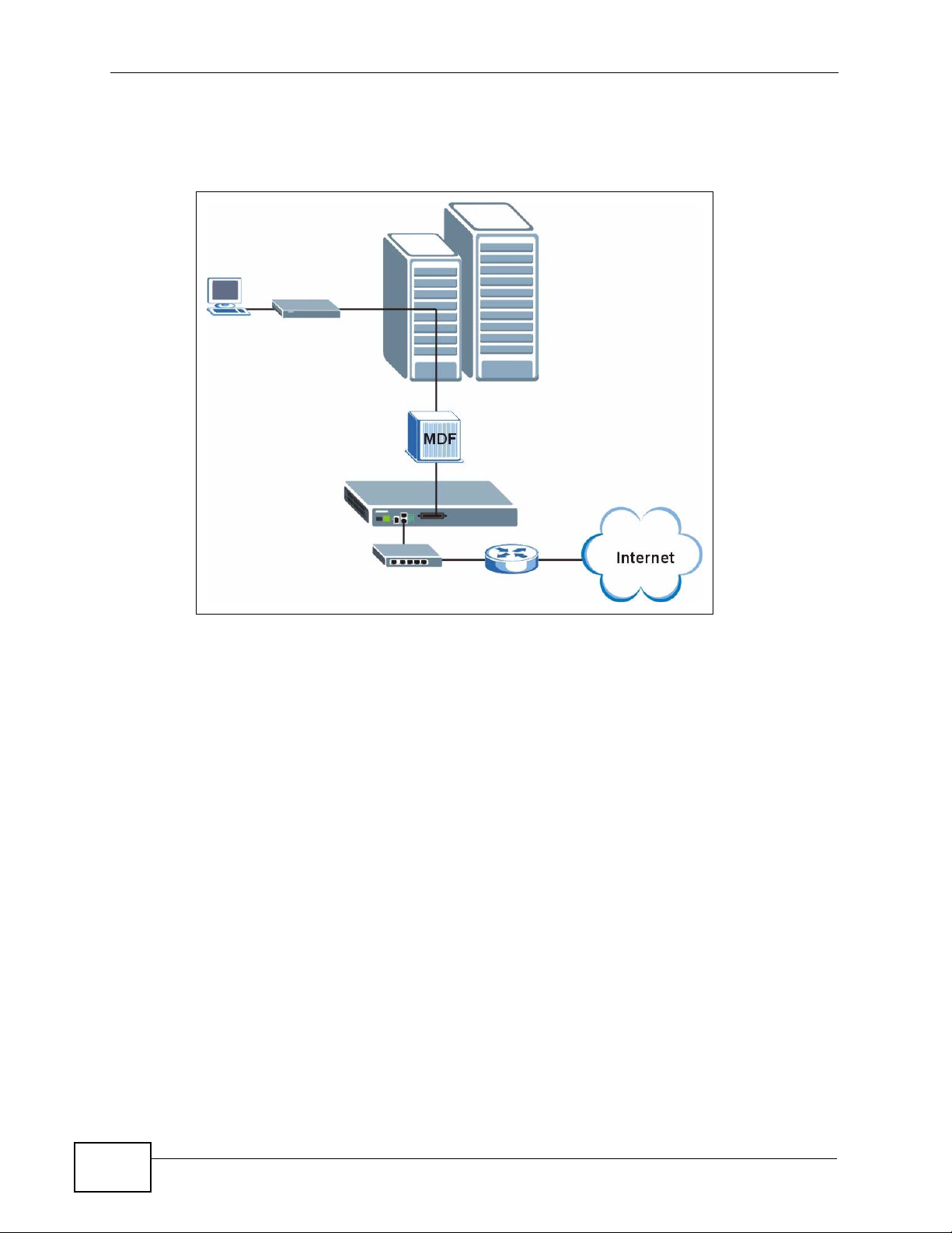
Chapter 1 Getting to Know the SAM1316-22
application leverages existing phone line wiring to provide Internet access to all
tenants.
Figure 1 MTU Application
1.2.2 Curbside Application
The SAM1316-22 can be used by an Internet Service Provider (ISP) in a street
cabinet to form a "mini POP (Point-of -Pres ence)" to provide broadband services to
30
SAM1316-22 User’s Guide
Page 31

Chapter 1 Getting to Know the SAM1316-22
residential areas that are too f a r away from the ISP to avail of DSL services.
Residents need a DSL modem, connected as shown in the previous figure.
Figure 2 Curbside Application
SAM1316-22 User’s Guide
31
Page 32

Chapter 1 Getting to Know the SAM1316-22
32
SAM1316-22 User’s Guide
Page 33

CHAPTER 2
Installing and Removing the
SAM1316-22
2.1 Overview
This chapter shows you how to install the SAM1316-22 in the IES-1000 and how
to remove it.
2.2 Installing the SAM1316-22 in the IES-1000
1 Hold the SAM1316-22 with the network ports facing you.
2 Insert it into an empty slot on the front of the IES-1000. Push the SAM1316-22
into the IES-1000 until the front of the SAM1316-22 is flush with the IES-1000.
Figure 3 Installation: Push the SAM1316-22 into the IES-1000
Note: The front of the SAM1316-22 must be flush with the front of the IES-1000.
SAM1316-22 User’s Guide
33
Page 34

Chapter 2 Installing and Removing the SAM1316-22
3 Turn the two screws on the front of the SAM1316-22 clockwise to secure the
SAM1316-22 to the chassis as shown below.
Figure 4 Installation: Tighten Module Screws
2.3 Removing the SAM1316-22 from the IES-1000
1 T urning the two screws that secure the module to the c hassis counter-clockwise to
loosen them.
Figure 5 Removal: Loosen Module Screws
2 Gently pull the SAM1316-22 out of the chassis as shown next.
Figure 6 Removal: Removing the SAM1316-22 from the IES-1000
34
SAM1316-22 User’s Guide
Page 35

Chapter 2 Installing and Removing the SAM1316-22
SAM1316-22 User’s Guide
35
Page 36

Chapter 2 Installing and Removing the SAM1316-22
36
SAM1316-22 User’s Guide
Page 37

CHAPTER 3
Front Panel
This chapter describes the front panel of the SAM1316-22, shown below.
Figure 7 Front Panel
The LEDs and ports are discussed in the following sections.
3.1 LEDs
The following table describes the LED indicators on the SAM1316-22.
Table 1 LEDs
LED COLOR STATUS DESCRIPTION
ALM Red On The temperature or voltage is abnormal.
SYS Green On The system is running.
LAN 10/
100
Off The temperature or voltage is normal.
Blinking The system is rebooting and performing self-
diagnostic tests.
Off The power is off or the system is not ready/
malfunctioning.
Green On The link to a 10 Mbps Ethernet network is up.
Blinking There is network traffic on a 10 Mbps Ethernet
network.
Off The link to a 10 Mbps Ethernet network is down.
Orange On The link to a 100 Mbps Ethernet network is up.
Blinking There is network traffic on a 100 Mbps Ethernet
network.
Off The link to a 100 Mbps Ethernet network is down.
SAM1316-22 User’s Guide
37
Page 38

Chapter 3 Front Panel
Table 1 LEDs (continued)
LED COLOR STATUS DESCRIPTION
1-16 Green On The DSL link is up.
Off The DSL link is down.
3.2 Front Panel Ports
The following table describes the port labels on the front panel.
Table 2 Front Panel Ports
LABEL DESCRIPTION
CONSOLE Only connect this port if you want to configure the SAM1316-22 using the
command line interface (CLI) via the console port.
LAN 10/100 Connect these ports to a computer, a hub, an Ethernet switch or router.
USER Connect the Telco-50 connector to subscribers.
Each port is discussed further in the following sections.
3.2.1 Console Port
For local management, you can use a computer with terminal emulation software
configured to the following parameters:
• VT100 terminal emulation
• 9600 bps
• No parity, 8 data bits, 1 stop bit
• No flow control
Connect the male 9-pin end of the console cable to the console port of the
SAM1316-22. Connect the female end to a serial port (COM1, COM2 or other COM
port) of your computer.
3.2.2 LAN (Ethernet) Ports
The factory default negotiation settings for the Ethernet ports on the SAM1316-22
are:
38
• Speed: Auto
•Duplex: Auto
SAM1316-22 User’s Guide
Page 39

Chapter 3 Front Panel
Connect the LAN port of your SAM1316-22 to an Ethernet WAN switch using a
straight-through Category 5 UTP (Unshielded Twisted Pair) cable with RJ-45
connectors.
You may stack multiple IES-1000 units up to the number of ports available on an
Ethernet switch as shown next.
Figure 8 LAN Ports: Stacking Multiple IES-1000 Units
3.2.3 USER Ports
Use a Telco-50 connector to connect the USER ports to other SHDSL devices. The
rest of this section introduces Telco-50 cables, MDF (Main Distribution Frames),
and explains how to connect the USER ports to MDF.
3.2.3.1 Telco-50 Cables
Telco-50 cables are used for data and voice applications with MDFs (Main
Distribution Frame), patch panels and distribution box es. They can also be used as
extension cables. Telco-50 cables are made up of 25 twisted-pair copper wires.
SAM1316-22 User’s Guide
39
Page 40

Chapter 3 Front Panel
Connect a Telco-50 connector to one end of the cable (see the hardware
specifications appendix for pin assignments) and connect the other end directly to
an MDF, RJ-11 connectors or directly to DSL modem(s).
Figure 9 Telco-50 Cable with RJ-11 Connectors
See Appendix C on page 443 for pin assignments.
3.2.3.2 Main Distribution Frame (MDF)
An MDF is usually installed between end-users' equipment and the telephone
company (CO) in a basement or telephone room. The MDF is the point of
40
SAM1316-22 User’s Guide
Page 41

Chapter 3 Front Panel
termination for the outside telephone company lines coming into a building and
the telephone lines in the building.
Figure 10 MDF Wiring
• Connect wiring from end-user equipment to the lower ports of an MDF using a
telephone wire. Connect wiring from the telephone company to the upper ports
of an MDF (see the previous figure).
• Some MDFs have surge protection circuitry built in between the two banks;
thus, do not connect telephone wires from the telephone company directly to
the SAM1316-22.
• Use a punch-down tool to seat telephone lines between MDF blocks.
3.2.3.3 Typical MDF Scenario
You want to install the SAM1316-22 in an environment where there are no
previously installed M DFs. There is no phone service and you wan t t o install the
SAM1316-22 for data-access only. No connections from the CO lines are
necessary.
SAM1316-22 User’s Guide
41
Page 42

Chapter 3 Front Panel
You may connect using an MDF or attach RJ-11 connectors to the non-SAM131622 end of the Telco-50 cable and then connect to DSL modems directly.
Figure 11 MDF Installation Scenario
1 Connect the Telco-50 connector end of the cable to the Telco-50 connector.
2 Connect the USER wiring on the other end of the Telco-50 cable to the upper ports
of the MDF using a punch-down tool.
3 Connect the telephone wiring from each end-user's DSL modem to the lower ports
of the MDF.
42
SAM1316-22 User’s Guide
Page 43

PART II
Technical Reference
43
Page 44

44
Page 45

CHAPTER 4
Introducing the Web
Configurator
4.1 Overview
This chapter tells how to access and navigate the web configurator.
The web configurator allows you to use a web browser to manage the SAM1316-
22.
4.2 Screen Privilege Levels
There is a high or low privilege level for each screen.
High privilege screens are only available to administrators with high privilege
access. High privilege screens include things like creating administrator accounts,
restarting the system, saving changes to the nonv olatile memory and resett ing to
factory defaults. Nonvolatile memory refers to the SAM1316-22’s storage that
remains even if the SAM1316-22’s power is turned off. Administrators with high
privilege access can use all screens including the lower privilege screens.
Administrators with the low privilege level are restricted to using only low privilege
screens. Low privilege screens are read only.
4.3 Accessing the Web Configurator
Use Internet Explorer 6 and later versions with JavaScript enabled.
Use the following instructions to log on to the web configurator.
SAM1316-22 User’s Guide
45
Page 46

Chapter 4 Introducing the Web Configurator
1 Launch your web browser, and enter the IP address of the SAM1316-22 (default:
192.168.1.1 is the factory default) in the Location or Address field. Press
Enter. The Login screen appears.
Figure 12 Login
2 Type admin in the User Name field and your password (default: 1234) in the
Password field. Click OK. The main screen appears.
This is the web configurator’s main screen.
Figure 13 Home
A
B
C
46
A - Click the menu items to open submenu links, and then click on a submenu link
to open the screen in the main window. See Section 4.4 on page 47 for more
information.
SAM1316-22 User’s Guide
Page 47

Chapter 4 Introducing the Web Configurator
B - Click this to open the Home screen. (This is the same screen that is display ed
above.) See Chapter 6 on page 59 for more information.
C - Click this to log out of the web configurator.
4.4 Navigation Panel
In the navigation panel, click a menu item to reveal a list of submenu links. Click a
submenu link to go to the corresponding screen.
Table 3 Navigation Panel Submenu Links
BASIC SETTING ADVANCED APPLICATION ROUTING PROTOCOL
ALARM MANAGEMENT CONFIG SAVE
SAM1316-22 User’s Guide
47
Page 48

Chapter 4 Introducing the Web Configurator
The following table briefly describes the functions of the screens that you open by
clicking the navigation panel’s sub-links.
Table 4 Web Configurator Screens
LABEL DESCRIPTION
Basic Setting
System
Information
General Setup Use this screen to configure general identification information about
User Account Use this screen to configure system administrator accounts.
Switch Setup Use this screen to set up system-wide parameters such as MAC
IP Setup Use this screen to configure the system and management IP
ENET Port Setup Use this screen to configure settings for the Ethernet ports.
xDSL Port Setup Use these screens for configuring settings for individual DSL ports.
xDSL Profiles
Setup
xDSL Line Data Use these screens for viewing DSL line operating values, bit allocation
G.bond This link takes you to screens where you can configure G.bond, letting
Advanced
Application
VLAN Use these screens for viewing and configuring the VLAN settings.
IGMP Use these screens to view IGMP status information and configure
Static Multicast Use this screen to configure static multicast entries.
Multicast VLAN Use these screens to set up multicast VLANs that can be shared
Filtering Use this screen to configure packet filtering.
MAC Filter Use this screen to configure MAC filtering for each port.
Spanning Tree
Protocol
Port
Authentication
Port Security Use this screen to limit the number of MAC address that can be
DHCP Relay Use this screen to configure the DHCP relay settings.
DHCP Snoop Use these screens to drop traffic from IP addresses not assigned by
Use this screen to display general system and hardware monitoring
information.
the device and the time and date settings.
address learning and priority queues.
addresses and subnet masks.
Use these screens for configuring profiles for the DSL ports.
and performance counters.
subscribers connect to an ISP using data streams spread over
multiple DSL lines.
IGMP settings and IGMP filters. You can also use these screens to set
up bandwidth requirements by multicast group or port and to set up
limits on the number of multicast groups to which a port can
subscribe.
among different subscriber VLANs on the network.
Use these screens to display Rapid Spanning Tree Protocol (RSTP)
information and configure RSTP settings.
Use these screens to configure RADIUS and IEEE 802.1x security
settings.
learned on a port.
the DHCP server and to look at a summary of the DHCP packets on
each port.
48
SAM1316-22 User’s Guide
Page 49

Chapter 4 Introducing the Web Configurator
Table 4 Web Configurator Screens (continued)
LABEL DESCRIPTION
2684 Routed
Mode
PPPoA to PPPoE Use this screen to enable PPPoA-to-PPPoE conversions on each port.
DSCP Use this screen to set up DSCP on each port and to convert DSCP
TLS PVC Use this screen to set up Transparent LAN Service (VLAN stacking, Q-
ACL Use this screen to set up Access Control Logic profiles and to assign
Downstream
Broadcast
SysLog Use this screen to configure the syslog settings.
Access Control Use this screen to configure service access control and configure
PPPoE
Intermediate
Agent
Maximum MTU
Size
PVC Upstream
Limit
OUI Filter Use this screen to configure the SAM1316-22 to filter packets based
Routing Protocol
Static Routing Use this screen to configure static routes. A static route defines how
Alarm
Alarm Status Use these screens to view the alarms that are currently in the system.
Alarm Event
Setup
Alarm Port Setup Use this screen to set the alarm severity threshold for for sending
Alarm History Use this screen to display the alarms that have been raised by the
Management
Maintenance Use this screen to perform firmware and configuration file
Diagnostic Use this screen to view system logs and test port(s).
MAC Table Use this screen to view the MAC addresses of devices attached to
Use this screen to configure the SAM1316-22 to handle 2684 routed
mode traffic.
values to IEEE 802.1p values.
in-Q) on each port.
them to each PVC.
Use this screen to block downstream broadcast packets from being
sent to specified VLANs on specified ports.
SNMP and remote management.
Use this screen to insert line information into client PPPoE PADI
(PPPoE Active Discovery Initialization) and PADR (PPPoE Active
Discovery Request) packets.
Use this screen to configure the Maximum Transmission Unit (MTU)
for the Ethernet interfaces. The Ethernet interfaces discard any
packets larger than this.
Use this screen to limit the transmission rate for upstream traffic by
PVC.
on the OUI (Organizationally Unique Identifier) used in the MAC
address to identify the manufacturer of a device.
the SAM1316-22 should forward traffic by configuring the TC P/IP
parameters manually.
Use these screens to view and set the severity levels of the alarms
and where the system is to send them.
SNMP traps or sys logs for alarms on an individual port(s).
SAM1316-22, including the severity level of an alarm(s) and the date/
time when the alarm occured.
maintenance as well as restart the system.
what ports.
SAM1316-22 User’s Guide
49
Page 50

Chapter 4 Introducing the Web Configurator
Table 4 Web Configurator Screens (continued)
LABEL DESCRIPTION
ARP Table Use this screen to view the MAC address to IP address resolution
table.
Config Save
Config Save Use this screen to save the device’s configuration into the nonvolatile
memory (the SAM1316-22’s storage that remains even if the
SAM1316-22’s power is turned off).
4.5 Changing Your Password
After you log in for the first time, it is recommended you change the default
administrator password. Click Basic Setting and then User Account to display
the User Account screen.
Figure 14 User Account
50
SAM1316-22 User’s Guide
Page 51

Chapter 4 Introducing the Web Configurator
Click the index number 1 to edit the default administrator account settings.
Figure 15 User Account
Enter the new password in the Password and Retype Password to confirm
fields, and click Modify. Do not forget to click Config Save before you exit the
web configurator. See Section 4.6 on page 51.
4.6 Saving Your Configuration
Click Apply in a configuration screen when you are done modifying the settings in
that screen to save your changes back to the run-time memory. Settings in the
run-time memory are lost when the SAM1316-22’s power is turned off.
Click Config Save in the navigation panel to save your configuration to
nonvolatile memory. Nonvolatile memory refers to the SAM1316-22’s stor age that
remains even if the SAM1316-22’s power is turned off.
Note: Use Config Save when you are done with a configuration session.
4.7 Logging Out of the Web Configurator
Click Logout in any screen to exit the web configurator. You have to log in with
your password again after you log out. This is recommended after you finish a
SAM1316-22 User’s Guide
51
Page 52

Chapter 4 Introducing the Web Configurator
management session both for security reasons and so you do not lock out other
device administrators.
Figure 16 Logout
52
SAM1316-22 User’s Guide
Page 53

CHAPTER 5
Initial Configuration
5.1 Overview
This chapter describes initial configuration for the SAM1316-22. See Appendix A
on page 435 for various default settings of the SAM1316-22.
It shows what you first need to do to provide service to DSL subscribers.
5.2 Initial Configuration
This chapter uses the web configurator for initial configuration. See the CLI
chapters for information on the commands. Use Internet Explorer 6 and later
versions with JavaScript enabled.
1 Log in to the web configurator. See Section 4.3 on page 45 for instructions.
2 In the navigation panel, click Basic Setting, IP Setup. The IP Setup screen
appears.
Figure 17 IP Setup
3 Use this screen to change the IP address, subnet mask, and default gateway IP
address for your network. Apply the settings.
SAM1316-22 User’s Guide
53
Page 54

Chapter 5 Initial Configuration
Note: If you change the IP address of the SAM1316-22, after you click Apply IP
setting, you have to use the new IP address to log into the web configurator
again.
4 If your subscribers use VPI 0 and VCI 33 (the default for all of the DSL ports), go
to step 13. Otherwise, use the following steps to change the VPI and VCI settings
for all of the DSL ports.
First, you will delete the default virtual channel from all of the DSL ports. (You
cannot edit it). Then, you will configure a new virtual channel for a port and copy
it to the other DSL ports.
Adding another virtual channel without deleting the default virtual channel is not
recommended since you cannot set the new channel to be the port’s super
channel. The super channel can forward frames belonging to multi ple VLAN groups
(that are not assigned to other channels). A channel that is not the super channel
can only forward frames with a single VLAN ID (that is configured on that
channel). In this case, the SAM1316-22 drops any frames received from the
subscriber that are tagged with another VLAN ID.
5 In the navigation panel, click Basic Setting, xDSL Port Setup. The xDSL Port
Setup screen appears.
Figure 18 xDSL Port Setup
54
SAM1316-22 User’s Guide
Page 55

6 Click VC Setup. The following screen appears.
Figure 19 VC Setup
Chapter 5 Initial Configuration
7 Select any virtual channel’s Select radio button, and click Delete. The following
screen appears.
Figure 20 VC Setup, Delete
8 Click OK. The following screen appears.
Figure 21 Select Ports
SAM1316-22 User’s Guide
55
Page 56

Chapter 5 Initial Configuration
9 Click All, and then click Apply. The VC Setup screen is updated.
Figure 22 VC Setup
10 Select Super Channel to allow the channel to forward frames belonging to
multiple VLAN groups (that are not assigned to other channels). Then, enter the
VPI and VCI that you use. Leave the other default settings, and click Add. The VC
Setup screen is updated.
Figure 23 VC Setup
56
SAM1316-22 User’s Guide
Page 57

Chapter 5 Initial Configuration
11 Select the new channel’s Select radio button. Click Copy, and then click Paste.
The following screen appears. The following screen appears.
Figure 24 Select Ports
12 Click All, and then click Apply. The VC Setup screen is updated.
Figure 25 VC Setup
SAM1316-22 User’s Guide
57
Page 58

Chapter 5 Initial Configuration
13 Click Config Save, Config Save. The Config Save screen appears.
Figure 26 Config Save
Note: Clicking Save in the Config Save > Config Save screen saves any changes,
including the new IP address of the SAM1316-22, in the Flash memory.
Otherwise, the SAM1316-22 reverts to the default settings (IP address is
192.168.1.1) once it is turned off.
14 Click Save. The following screen should appear.
Figure 27 Config Save, Save Successful
You can now use the device (with the other settings set to the defaul ts) to provide
service to DSL subscribers. See Appendix A on page 435 for information on other
default settings.
58
SAM1316-22 User’s Guide
Page 59

CHAPTER 6
Home and Port Statistics
Screens
This chapter describes the Home (status), Port Statistics, and RMON screens.
6.1 Home Screen
The Home screen of the web configur ator displays a port statisti cal summary with
links to each port showing statistical details.
To open this screen, click Home in any web configurator screen.
Figure 28 Home
The following table describes the labels in this screen.
Table 5 Home
LABEL DESCRIPTION
System up Time This field shows how long the system has been running since the last
time it was started.
The following fields are related to the Ethernet ports.
SAM1316-22 User’s Guide
59
Page 60

Chapter 6 Home and Port Statistics Screens
Table 5 Home (continued)
LABEL DESCRIPTION
ENET This field displays the number of the Ethernet port. Click a port
number to display that port’s statistics screen. The Ethernet Port
Statistics Screen appears. See Section 6.1.1 on page 61.
Status This field displays whether the Ethernet port is connected (Up) or not
(Down).
Port Name This field displays the name of the Ethernet port.
Media This field displays the type of media that this Ethernet port is using
for a connection. “-“ displays when the port is disabled or not
connected.
Duplex This field displays whether the port is using half or full-duplex
communication. “-“ displays when the port is disabled or not
connected.
Up Time This field shows the total amount of time in hours, minutes and
seconds the port’s connection has been up. “--:--:--“ displays when
the port is disabled or not connected.
The following fields are related to the xDSL ports.
xDSL This identifies the xDSL port. Click a port number to display that
port’s statistics screen. The DSL Port Statistics Screen appears. See
Section 6.1.2 on page 64.
Status This field shows whether the port is connected (Up) or not (Down).
Actual Rate This field shows the interface's current bandwidth in kilobits per
second. For interfaces that do not vary in bandwidth or for those
where no accurate estimation can be made, this object should contain
the nominal bandwidth.
Up Time This field shows the total amount of time in hours, minutes and
seconds the port’s connection has been up. “-“ displays when the port
is not connected.
The following fields and buttons apply to the whole screen.
Poll Interval(s)
Set Interval
Stop Click Stop to halt system statistic polling.
Port
Clear Counter
Reset Click this to set the Poll Interval(s) and Port fields to their default
The text box displays how often (in seconds) this screen refreshes.
You may change the refresh interval by typing a new number in the
text box and then clicking Set Interval.
Select a port from the Port drop-down list box and then click Clear
Counter to erase the recorded statistical information for that port.
values and to refresh the screen.
60
SAM1316-22 User’s Guide
Page 61

Chapter 6 Home and Port Statistics Screens
6.1.1 Ethernet Port Statistics Screen
Use this screen to display statistics about an Ethernet port. To open this screen,
click an Ethernet port’s number in the Home screen.
Figure 29 Port Statistics (Ethernet)
The following table describes the labels in this screen.
Table 6 Port Statistics (Ethernet)
LABEL DESCRIPTION
RMON Click this to open the RMON Statistics screen.
Up Click this to go back to the Home screen.
Port Use this drop-down list box to select a port for which you wish to view
statistics. This field identifies the port described in this screen.
Port Name This field displays the name that you have configured for the port.
Rx bytes This field shows the number of octets of Ethernet frames received
that are from 0 to 1518 octets in size, counting the ones in bad
packets, not counting framing bits but counting FCS (Frame Check
Sequence) octets. An octet is an 8-bit binary digit (byte).
Rx packets This field shows the number of packets received on this port
(including multicast, unicast, broadcast and bad packets).
Rx error fcs This field shows the number of frames received with an integral
length of 64 to 1518 octets and containing a Frame Check Sequence
error.
Rx multicast This field shows the number of good multicast frames received of 64
to 1518 octets in length (for non VLAN) or 1522 octets (for VLAN),
not including Broadcast frames. Frames with range or length errors
are also not taken into account.
SAM1316-22 User’s Guide
61
Page 62

Chapter 6 Home and Port Statistics Screens
Table 6 Port Statistics (Ethernet) (continued)
LABEL DESCRIPTION
Rx broadcast This field shows the number of good broadcast frames received of 64
to 1518 octets in length (for non VLAN) or 1522 octets (for VLAN),
not including multicast frames. Frames with range or length errors
are also not taken into account.
Rx mac pause This field shows the number of valid IEEE 802.3x Pause frames
received on this port.
Rx fragments This field shows the number of frames received that were less than 64
octets long, and contained an invalid FCS, including non-integral and
integral lengths.
Rx error overrun This field shows how many times an Ethernet transmitter overrun
occurred.
Rx error mru This field shows the number of received frames that were dropped
due to exceeding the Maximum Receive Unit frame size.
Rx dropped This field shows the number of received frames that were received
into the SAM1316-22, but later dropped because of a lack of system
resources.
Rx jabber This field shows the number of frames received that were longer than
1518 octets (non VLAN) or 1522 octets (VLAN) and contained an
invalid FCS, including alignment errors.
Rx error
alignment
Rx oversize This field shows the number of frames received that were bigger than
Rx undersize This field shows the number of frames received that were less than 64
Rx discard This field shows the number of frames dropped based on packet
Tx bytes This field shows the number of bytes that have been transmitted on
Tx packets This field shows the number of packets transmitted on this port.
Tx multicast This field shows the number of good multicast frames transmitted on
Tx broadcast This field shows the number of broadcast frames transmitted on this
Tx mac_pause This field shows the number of valid IEEE 802.3x Pause frames
Tx fragments This field shows the number of transmitted frames that were less than
Tx frames This field shows the number of complete good frames transmitted on
Tx error underrun This field shows the number of outgoing frames that were less than
Tx undersize This field shows the number of frames transmitted that were less than
This field shows the number of frames received that were 64 to 1518
(non VLAN) or 1522 (VLAN) octets long but contained an invalid FCS
and a non-integral number of octets.
1518 (non VLAN) or 1522 (VLAN) octets and contained a valid FCS.
octets long and contained a valid FCS.
filtering.
this port. This includes collisions but not jam signal or preamble/SFD
(Start of Frame Delimiter) bytes.
this port (not including broadcast frames).
port (not including multicast frames).
transmitted on this port.
64 octets long, and with an incorrect FCS value.
this port.
64 octets long.
64 octets long and contained a valid FCS.
62
SAM1316-22 User’s Guide
Page 63

Chapter 6 Home and Port Statistics Screens
Table 6 Port Statistics (Ethernet) (continued)
LABEL DESCRIPTION
Tx jabber This field shows the number of frames transmitted that were longer
than 1518 octets (non VLAN) or 1522 octets (VLAN) and contained an
incorrect FCS value.
Tx oversize This field shows the number of frames transmitted that were bigger
than 1518 octets (non VLAN) or 1522 (VLAN) and contained a valid
FCS.
packet(<=64) This field shows the number of frames received and transmitted
(including bad frames) that were 64 octets or less in length (this
includes FCS octets but excludes framing bits).
packet(65-127) This field shows the number of frames received and transmitted
(including bad frames) that were 65 to 127 octets in length (this
includes FCS octets but excludes framing bits).
packet(128-255) This field shows the number of frames received and transmitted
(including bad frames) that were 128 to 255 octets in length (this
includes FCS octets but excludes framing bits).
packet(256-511) This field shows the number of frames received and transmitted
(including bad frames) that were 256 to 511 octets in length (this
includes FCS octets but excludes framing bits).
packet(512-
1023)
packet(1024-
1518)
packet(1522) This field shows the number of frames received and transmitted
packet(total) This field shows the total number of received and transmitted
broadcast(total) This field shows the total number of received and transmitted
multicast(total) This field shows the total number of received and transmitted
octet(total) This field shows the total number of received and transmitted octets
Poll Interval(s)
Set Interval
Stop Click Stop to halt system statistic polling.
Port
Clear Counter
Reset Click this to set the Poll Interval(s) and Port fields to their default
This field shows the number of frames received and transmitted
(including bad frames) that were 512 to 1023 octets in length (this
includes FCS octets but excludes framing bits).
This field shows the number of frames received and transmitted
(including bad frames) that were 1024 to 1518 octets in length (this
includes FCS octets but excludes framing bits).
(including bad frames) that were 1519 to 1522 octets in length (this
includes FCS octets but excludes framing bits).
packets.
broadcast frames.
multicast frames.
(unicast, multicast and broadcast).
The text box displays how often (in seconds) this screen refreshes.
You may change the refresh interval by typing a new number in the
text box and then clicking Set Interval.
Select a port from the Port drop-down list box and then click Clear
Counter to erase the recorded statistical information for that port.
values and to refresh the screen.
SAM1316-22 User’s Guide
63
Page 64

Chapter 6 Home and Port Statistics Screens
6.1.2 DSL Port Statistics Screen
Use this screen to display statistics about a DSL port. To open this screen, click a
DSL port’s number in the Home screen.
Figure 30 Port Statistics (DSL)
64
The following table describes the labels in this screen.
Table 7 Port Statistics (DSL)
LABEL DESCRIPTION
RMON Click this to open the RMON Statistics screen.
Up Click this to go back to the Home screen.
xDSL Port Use this drop-down list box to select a port for which you wish to view
statistics. This field identifies the port described in this screen.
Port Name This field displays the name that you have configured for the port. If
you have not configured a name, it is blank.
Tx packets This field shows the number of packets transmitted on this port.
Rx packets This field shows the number of packets received on this port.
Tx broadcast
packets
Rx broadcast
packets
This field shows the number of broadcast packets transmitted on this
port.
This field shows the number of broadcast packets received on this
port.
SAM1316-22 User’s Guide
Page 65

Chapter 6 Home and Port Statistics Screens
Table 7 Port Statistics (DSL) (continued)
LABEL DESCRIPTION
Tx discard
packets
Rx discard
packets
Errors This field shows the number of AAL5 frames received with CRC errors.
Tx rate This field shows the number of kilobytes per second transmitted on
Rx rate This field shows the number of kilobytes per second received on this
Tx bytes This field shows the number of bytes that have been transmitted on
Rx bytes This field shows the number of bytes that have been received on this
VPI/VCI This field displays the Virtual Path Identifier (VPI) and Virtual Circuit
Tx Packets This field shows the number of packets transmitted on each channel.
Rx Packets This field shows the number of packets received on each channel.
Tx rate This field shows the number of bytes per second transmitted on each
Rx rate This field shows the number of bytes per second received on each
Tx cells This field shows the number of ATM cells transmitted on each channel.
Rx cells This field shows the number of ATM cells received on each channel.
Errors This field shows the number of error packets on each channel.
Poll Interval(s)
Set Interval
Stop Click Stop to halt system statistic polling.
Port
Clear Counter
Reset Click this to set the Poll Interval(s) and Port fields to their default
This field shows the number of outgoing packets that were dropped
on this port. The “Tx discard packets” counter always displays “0”
because the SAM1316-22 does not discard packets that it sends.
This field shows the number of received packets that were dropped on
this port. Some of the possible reasons for the discarding of received
(rx) packets are:
• The packet filter is enabled and the packets matched a packet
filter.
• The MAC filter is enabled and the SAM1316-22 dropped the
packets according to the MAC filter’s configuration.
• The packets contained frames with an invalid VLAN ID.
this port.
port.
this port.
port.
Identifier (VCI) of channels on this port.
channel.
channel.
The text box displays how often (in seconds) this screen refreshes.
You may change the refresh interval by typing a new number in the
text box and then clicking Set Interval.
Select a port from the Port drop-down list box and then click Clear
Counter to erase the recorded statistical information for that port.
values and to refresh the screen.
SAM1316-22 User’s Guide
65
Page 66

Chapter 6 Home and Port Statistics Screens
6.1.3 RMON Statistics Screen
Use this screen to display RMON statistics about a port. To open this screen, click
RMON in the DSL Port Statistics screen or Ethernet Port Statistics screen.
Figure 31 Port Statistics (RMON)
66
The following table describes the labels in this screen.
Table 8 Port Statistics (RMON)
LABEL DESCRIPTION
Port Statistics Click this to go back to the previous screen.
Enet1 Click this to look at the RMON history for this port.
Enet2 Click this to look at the RMON history for this port.
EtherStatsDropEvents This field displays the total number of packets that were
dropped on this port.
EtherStatsOctets This field displays the total number of octets received/
transmitted on this port.
EtherStatsPkts This field displays the total number of good packets
received/transmitted on this port.
SAM1316-22 User’s Guide
Page 67

Chapter 6 Home and Port Statistics Screens
Table 8 Port Statistics (RMON) (continued)
LABEL DESCRIPTION
EtherStatsBroadcastPkts This field displays the total number of broadcast packets
received/transmitted on this port.
EtherStatsMulticastPkts This field displays the total number of multicast packets
received/transmitted on this port.
EtherStatsCRCAlignErrors This field di splays the total number of CRC (Cyclical
Redundancy Check) alignment errors on this port.
EtherStatsUndersizePkts This field displays the total number of packets that were
too small received/transmitted on this port.
EtherStatsOversizePkts This field displays the total number of packets that were
too big received/transmitted on this port.
EtherStatsFragments This is the number of frames received/transmitted that
were less than 64 octets long, and contained an invalid
FCS, including non-integral and integral lengths.
EtherStatsJabbers This is the number of frames received/transmitted that
were longer than 1518 octets (non VLAN) or 1522 octets
(VLAN) and contained an invalid FCS, including alignment
errors.
EtherStatsCollisions This is the number of frames for which transmission failed
due to excessive collisions. Excessive collision is defined
as the number of maximum collisions before the
retransmission count is reset.
EtherStats64Octets This is the number of frames received/transmitted
(including bad frames) that were 64 octets or less in
length (this includes FCS octets but excludes framing
bits).
EtherStats65to127Octets This is the number of frames received/transmitted
(including bad frames) that were 65 to 127 octets in
length (this includes FCS octets but excludes framing
bits).
EtherStats128to255Octets This is the number of frames received and transmitted
(including bad frames) that were 128 to 255 octets in
length (this includes FCS octets but excludes framing
bits).
EtherStats256to511Octets This is the number of frames received/transmitted
(including bad frames) that were 256 to 511 octets in
length (this includes FCS octets but excludes framing
bits).
EtherStats512to1023Octets This is the number of frames received/transmitted
(including bad frames) that were 512 to 1023 octets in
length (this includes FCS octets but excludes framing
bits).
EtherStats1024to1518Octets This is the number of frames received/transmitted
(including bad frames) that were 1024 to 1518 octets in
length (this includes FCS octets but excludes framing
bits).
Poll Interval(s)
Set Interval
The text box displays how often (in seconds) this screen
refreshes. You may change the refresh interval by typing
a new number in the text box and then clicking Set
Interval.
SAM1316-22 User’s Guide
67
Page 68

Chapter 6 Home and Port Statistics Screens
Table 8 Port Statistics (RMON) (continued)
LABEL DESCRIPTION
Stop Click Stop to halt system statistic polling.
Port
Clear Counter
Reset Click this to set the Poll Interval(s) and Port fields to
6.1.4 RMON History Screen
Use this screen to display general information (such as sample time) on history
samples. To op en this screen, click any port number in the RMON Statistics
screen.
Figure 32 Port Statistics (RMON History))
Select a port from the Port drop-down list box and then
click Clear Counter to erase the recorded statistical
information for that port.
their default values and to refresh the screen.
68
The following table describes the labels in this screen.
Table 9 Port Statistics (RMON History)
LABEL DESCRIPTION
Index:Interval Select the index of the sample interval and the desired data sampling
time (in seconds).
Apply Click this to use the selected data sampling time.
Refresh Click this to update this screen.
Sample Index This field display the sample number.
Interval Start This field displays the data sampling time.
Pkts This field displays the number of packets received or transmitted
since the last sample time.
BroadcastPkts This field displays the number of broadcast packets received or
transmitted since the last sample time.
MulticastPkts This field displays the number of multicast packets received/
transmitted since the last sample time.
Utilization This field displays the port utilization status.
SAM1316-22 User’s Guide
Page 69

6.1.5 RMON History Detail Screen
Use this screen to display detailed RMON history. To open this screen, click any
index number in the RMON History screen.
Figure 33 Port Statistics (RMON History Detail))
Chapter 6 Home and Port Statistics Screens
The following table describes the labels in this screen.
Table 10 Port Statistics (RMON History Detail)
LABEL DESCRIPTION
UP Click this to return to the previous screen.
Refresh Click this to update this screen.
Index This field displays the index of the sample interval.
Sample Index This field displays the sample number.
Interval Start This field displays the data sampling time.
Drop Events This field displays the total number of packets that were dropped in
the sampling period.
Octets This field displays the total number of octets received/transmitted in
the sampling period.
Pkts This field displays the total number of good packets received/
transmitted in the sampling period.
BroadcastPkts This field displays the total number of broadcast packets received/
transmitted in the sampling period.
MulticastPkts This field displays the total number of multicast packets received/
transmitted in the sampling period.
SAM1316-22 User’s Guide
69
Page 70

Chapter 6 Home and Port Statistics Screens
Table 10 Port Statistics (RMON History Detail) (continued)
LABEL DESCRIPTION
CRCAlignErrors This field displays the total number of CRC (Cyclical Redundancy
Check) alignment errors in the sampling period.
UndersizePkts This field displays the total number of packets that were too small
received/transmitted in the sampling period.
OversizePkts This field displays the total number of packets that were too big
received/transmitted in the sampling period.
Fragments This is the number of frames received/transmitted that were less than
64 octets long, and contained an invalid FCS, including non-integral
and integral lengths.
Jabbers This is the number of frames received/transmitted that were longer
than 1518 octets (non VLAN) or 1522 octets (VLAN) and contained an
invalid FCS, including alignment errors.
Collisions This is the number of frames for which transmission failed due to
excessive collisions. Excessive collision is defined as the number of
maximum collisions before the retransmission count is reset.
Utilizations This field displays the port utilization status in the sampling period.
70
SAM1316-22 User’s Guide
Page 71

CHAPTER 7
System Information
The System Information screen displays general device information (such as
firmware version number) and hardware polling information (such as temper ature
status). Y o u can check the firmware version number and monitor the hardware
status in this screen.
To open this screen, click Basic Setting, System Information.
Figure 34 System Info
SAM1316-22 User’s Guide
71
Page 72

Chapter 7 System Information
The following table describes the labels in this screen.
Table 11 System Info
LABEL DESCRIPTION
System Name This field displays the device's model name.
ZyNOS F/W
Version
DSL Driver
Version
DSP Code Version This field displays the Digital Signal Processor firmware version
Hardware Version This is the version of the physical device hardware. This field may be
Serial Number This is the individual identification number assigned to the device at
Ethernet Address This field refers to the Ethernet MAC (Media Access Control) address
Hardware Monitor
Enable Select this check box to turn the hardware monitor on or clear it to
Temperature Unit Select C to display all temperature measurements in degrees Celsius.
Temperature Each temperature sensor can detect and report the temperature.
Current This shows the current temperature at this sensor.
MAX This field displays the maximum temperature measured at this
MIN This field displays the minimum temperature measured at this sensor.
Average This field displays the average temperature measured at this sensor.
Threshold (Low) This field displays the lowest temperature limit at this sensor.
Threshold (Hi) This field displays the highest temperature limit at this sensor.
Status This field displays Normal for temperatures below the threshold and
Voltage(V) The power supply for each voltage has a sensor that can detect and
Current This is the current voltage reading.
MAX This field displays the maximum voltage measured at this point.
MIN This field displays the minimum voltage measured at this point.
Average This field displays the average voltage measured at this sensor.
Threshold (Low) This field displays the lowest voltage limit at this sensor.
Threshold (Hi) This field displays the highest voltage limit at this sensor.
Status Normal indicates that the voltage is within an acceptable operating
This field displays the version number of the device’s current firmware
including the date created.
This field displays the Digital Subscriber Line firmware version
number.
number. This is the modem code firmware.
blank.
the factory. This field may be blank.
of the device.
turn the hardware monitor off.
Select F to display all temperature measurements in degrees
Fahrenheit.
Temperature sensor 1 is near the DSL chipset. Temperature sensor 2
is near the central processing unit. Temperature sensor 3 is at the
hardware monitor chip.
sensor.
Over for those above.
report the voltage.
range at this point; otherwise Abnormal is displayed.
72
SAM1316-22 User’s Guide
Page 73

Chapter 7 System Information
Table 11 System Info (continued)
LABEL DESCRIPTION
Use this section of the screen to configure the hardware monitor
threshold settings.
New threshold
Apply
Index This field is a sequential value.
Temperature (Hi) Use these fields to configure the highest temperature limit at each
Temperature (Lo) Use these fields to configure the lowest temperature limit at each
Volt. (Hi) Use these fields to configure the highest voltage limit at each sensor.
Volt. (Lo) Use these fields to configure the lowest voltage limit at each sensor.
Poll Interval(s)
Set Interval
Stop Click Stop to halt statistic polling.
Configure new threshold settings in the fields below and click Apply
to use them.
sensor.
sensor.
The text box displays how often (in seconds) this screen refreshes.
You may change the refresh interval by typing a new number in the
text box and then clicking Set Interval.
SAM1316-22 User’s Guide
73
Page 74

Chapter 7 System Information
74
SAM1316-22 User’s Guide
Page 75

CHAPTER 8
General Setup
The General Setup screen allows you to configure general device identification
information. It also allows you to set the system time manually or get the current
time and date from an external server when you turn on your device. The real
time is then displayed in the logs.
To open this screen, click Basic Setting, General Setup.
Figure 35 General Setup
SAM1316-22 User’s Guide
75
Page 76

Chapter 8 General Setup
The following table describes the labels in this screen.
Table 12 General Setup
LABEL DESCRIPTION
Host Name Choose a descriptive name for identification purposes. This name
Location Enter the geographic location of your device. You can use up to 31
Contact Person's
Name
Model This field displays your device type.
Stdio Timeout Enter how many minutes of inactivity the SAM1316-22 waits before
Slot ID If you have several SAM1316-22s in your network, you can use this
Use Time Server
When Bootup
consists of up to 31 ASCII characters; spaces are allowed.
ASCII characters; spaces are allowed.
Enter the name of the person in charge of this device. Y ou can use up
to 31 ASCII characters; spaces are allowed.
automatically disconnecting a session. You need to enter the
username and password again before accessing the W eb Configurator.
field to identify them. This may be required by some services such as
DHCP or PPPoE. If it’s not required, you can leave the default value 0.
Select the time service protocol that the timeserver uses. Not all time
servers support all protocols, so you may have to use trial and error
to find a protocol that works. The main differences between them are
the time format.
When you select the Daytime (RFC 867) format, the switch displa ys
the day, month, year and time with no time zone adjustment. When
you use this format it is recommended that you use a Daytime
timeserver within your geographical time zone. Time (RFC-868)
format displays a 4-byte integer giving the total number of seconds
since 1970/1/1 at 0:0:0.
NTP (RFC-1305) is similar to Time (RFC-868).
None is the default value. Enter the time manually. Each time you
turn on the device, the time and date will be reset to 2000-1-1 0:0.
Time Server IP
Address
Current Time This field displays the time you open this menu (or refresh the menu).
New Time
(hh:min:ss)
Current Date This field displays the date you open this menu.
New Date (yyyy-
mm-dd)
Time Zone Select the time difference between UTC (Universal Time Coordinated,
Apply Click Apply to save your changes to the SAM1316-22’s volatile
Cancel Click Cancel to start configuring the screen again.
Enter the IP address of your timeserver. The device searches for the
timeserver for up to 60 seconds.
Enter the new time in hour, minute and second format. The new time
then appears in the Current Time field after you click Apply.
Enter the new date in year, month and day format. The new date then
appears in the Current Date field after you click Apply.
formerly known as GMT, Greenwich Mean Time) and your time zone
from the drop-down list box.
memory. The SAM1316-22 loses these changes if it is turned off or
loses power, so use the Config Save link on the navigation panel to
save your changes to the non-volatile memory when you are done
configuring.
76
SAM1316-22 User’s Guide
Page 77

CHAPTER 9
User Account
The User Account screens allows you to set up and configure system
administrator accounts for the SAM1316-22. You can also configure the
authentication policy for SAM1316-22 administrators. This is different than port
authentication in Chapter 24 on page 175.
See Chapter 24 on page 175 for background information on authentication.
9.1 User Account Screen
To open this screen, click Basic Setting, User Account.
Figure 36 User Account
SAM1316-22 User’s Guide
77
Page 78

Chapter 9 User Account
The following table describes the labels in this screen.
Table 13 User Account
LABEL DESCRIPTION
Authentication Click this to open the Authentication screen. See Section 9.2 on
Enable Select this check box to turn on the administrator account.
Name Enter a user name for the administrator account.
Password Enter a password for the administrator account.
Retype Password
to Confirm
Privilege Select a privilege level to determine which screens the administrator
page 78.
Re-enter the administrator account’s password to v erify that you have
entered it correctly.
can use. There is a high, medium or low privilege level for each
command.
Select high to allow the administrator to use all commands including
the lower privilege commands. High privilege commands include
things like creating administrator accounts, restarting the system and
resetting the factory defaults.
Select middle to allow the administrator to use middle or low
privilege commands.
Select low to allow the administrator to use only low privilege
commands. Low privilege commands are read only.
Add Click Add to save your changes to the SAM1316-22’s volatile
memory. The SAM1316-22 loses these changes if it is turned off or
loses power, so use the Config Save link on the navigation panel to
save your changes to the non-volatile memory when you are done
configuring.
Cancel Click Cancel to begin configuring the fields again.
Index This field displays the number of the user account. Click an account’s
index number to use the top of the screen to edit it.
Enable This field displays a “V “ if you have the administrator account turned
on. It displays a “-“ if the administrator account is turned off.
Name This field displays the administrator account’s user name.
Privilege This field displays the administrator account’s access level (high,
middle or low).
Select Select this check box and click the Delete button to remove an
administrator account.
Delete Select an administrator account’s check box and click this button to
remove the administrator account.
Cancel Click Cancel to start configuring the screen afresh.
9.2 Authentication Screen
Use this screen to set up the authentication policies and settings by which
administrators can access the SAM1316-22.
78
SAM1316-22 User’s Guide
Page 79

Chapter 9 User Account
To open this screen, click Basic Setting, User Account, Authentication.
Figure 37 Authentication
The following table describes the labels in this screen.
Table 14 User Account
LABEL DESCRIPTION
User account Click this to open the User Account screen. See Section 9.1 on page
77.
Authentication
Mode
Select the process by which the SAM1316-22 authenticates
administrators.
local - Search the local database. You maintain this database in the
User Account screen.
radius - Check an external RADIUS database using the settings
below.
local then radius - Search the local database; if the user name is
not found, check an external RADIUS database using the settings
below.
IP Enter the IP address of the external RADIUS server in dotted decimal
notation.
Port The default UDP port of the RADIUS server for authentication is
1812. You need not change this value unless your network
administrator instructs you to do so.
SAM1316-22 User’s Guide
79
Page 80

Chapter 9 User Account
Table 14 User Account (continued)
LABEL DESCRIPTION
Secret Specify a password (up to 31 alphanumeric characters) as the key to
Default Privilege
Level
be shared between the external RADIUS server and the switch. This
key is not sent over the network. This key must be the same on the
external RADIUS server and the switch.
Select the privilege level assigned to administrators in case the
external RADIUS database does not provide one. The privilege level
determines which screens the administrator can use. There is a high,
medium or low privilege level for each command. You can also choose
to deny access to the SAM1316-22.
Select high to allow the administrator to use all commands including
the lower privilege commands. High privilege commands include
things like creating administrator accounts, restarting the system and
resetting the factory defaults.
Select middle to allow the administrator to use middle or low
privilege commands.
Select low to allow the administrator to use only low privilege
commands. Low privilege commands are read only.
Select deny to prevent the administrator from accessing the
SAM1316-22.
80
SAM1316-22 User’s Guide
Page 81

CHAPTER 10
Switch Setup
The Switch Setup screen allows you to set up and configure global device
features.
10.1 GARP Timer Setup
GARP (Generic Attribute Registration Protocol) allows network devices to register
and de-register attribute values with other GARP participants within a bridged
LAN. GARP is a protocol that provides a generic mechanism for protocols that
serve a more specific application, for example, GVRP (GARP VLAN Registration
Protocol). GARP and GVRP are the protocols used to automatically register VLAN
membership across switches.
Switches join VLANs by making a declaration. A declaration is made by issuing a
Join message using GARP. Declarations are withdrawn by issuing a Leave
message. A Leave All message terminates all registrations. GARP timers set
declaration timeout values.
10.2 Switch Modes
The SAM1316-22 supports standalone and daisychain switch modes.
10.2.1 Standalone Switch Mode
“Standalone switch mode” relates to the SAM1316-22’ s operational beha vior, not a
standalone network topology. The standalone switch mode allows either or both of
the SAM1316-22’s Ethernet ports to connect to the backbone Ethernet network.
You can also connect one of the SAM1316-22’s Ethernet ports to the Ethernet
network and the other to another SAM1316-22 (see Figure 38 on page 82 for an
example). When the SAM1316-22 is in standalone mode, you can use it in a
network topology that uses loops (you should also enable RSTP). You can have
multiple SAM1316-22 connected on the same network and set both of them to use
standalone mode in order to use them with a network topology that uses loops.
SAM1316-22 User’s Guide
81
Page 82

Chapter 10 Switch Setup
Standalone switch mode with port isolation enabled blocks communications
between subscriber ports on an individual SAM1316-22. However, one SAM131622’s subscribers can communicate with another SAM1316-22’s subscribers if the
two SAM1316-22’s Ethernet ports are connected to each other (see Figure 38 on
page 82 for an example). If you have multiple SAM1316-22 connected on the
same network and set to standalone mode, they do not all need to have the same
port isolation setting.
10.2.2 Port Isolation with Standalone Switch Mode Example
The following graphic shows SAM1316-22 1 and 2 connected to each other and
the Ethernet backbone switch (3) in a network topology that creates a loop. The
SAM1316-22 are using the standalone switch mode and have RSTP enabled.
In this example, both SAM1316-22 have port isolation turned on. Communications
between A and B must first go through another switch (3 in the figure). However,
A and B can communicate with C without their communications going through
another switch or router.
Figure 38 Port Isolation with Standalone Switch Mode Example
10.2.3 Daisychain Switch Mode
Daisychain switch mode sets the SAM1316-22 to use Ethernet port one (ENET 1)
as an uplink port to connect to the Ethernet backbone and Ethernet port two
(ENET 2) to connect to another (daisychained or subtending) SAM1316-22. The
daisychain switch mode is recommended for use in a network topology that does
82
SAM1316-22 User’s Guide
Page 83

Chapter 10 Switch Setup
not have loops. When you daisychain multiple SAM1316-22 they must all be set to
daisychain mode.
Daisychain switch mode with port isolation enabled blocks communications
between subscriber ports on an individual SAM1316-22 and between the
subscribers of any daisychained SAM1316-22 (see Figure 39 on page 83 for an
example). Use the same port isolation setting on all SAM1316-22 that you set up
in a daisychain.
10.2.4 Port Isolation with Daisychain Switch Mode Example
In the example below, the SAM1316-22 1 has its Ethernet port one (ENET 1)
connected to the Ethernet backbone switch (3) and it’s Ethernet port two (ENET 2)
connected to Ethernet port one (ENET 1) of the daisychained SAM1316-22 (2).
With port isolation turned on, communications between A and B must first go
through another switch or router (3 in the figure). A and B also cannot
communicate with C without their communications going through another switch
or router.
Figure 39 Port Isolation with Daisychain Switch Mode Example
SAM1316-22 User’s Guide
83
Page 84

Chapter 10 Switch Setup
10.3 Switch Setup Screen
To open this screen, click Basic Setting, Switch Setup.
Figure 40 Switch Setup
84
SAM1316-22 User’s Guide
Page 85

Chapter 10 Switch Setup
The following table describes the labels in this screen.
Table 15 Switch Setup
LABEL DESCRIPTION
MAC Address
Learning
Aging Time
Join Timer Join Timer sets the duration of the Join Period timer for GVRP in
Leave Timer Leave Timer sets the duration of the Leave Period timer for GVRP in
Leave All Timer Leave All Timer sets the duration of the Leave All Period timer for
Port Isolation
Active
MAC Anti-
Spoofing
Switch Mode Select Standalone to use both of the SAM1316-22’s Ethernet ports
Enter a time from 10 to 10,000 seconds. This is how long all
dynamically learned MAC addresses remain in the MAC address table
before they age out (and must be relearned). Enter 0 to disable the
aging out of MAC addresses.
GARP Timer: Switches join VLANs by making a declaration. A
declaration is made by issuing a Join message using GARP.
Declarations are withdrawn by issuing a Leave message. A Leave All
message terminates all registrations. GARP timers set declaration
timeout values. Click here for more information on VLANs.
milliseconds. Each port has a Join Period timer. The allowed Join Time
range is between 100 and 65535 milliseconds; the default is 200
milliseconds.
milliseconds. Each port has a single Leave Period timer. Leave Time
must be two times larger than Join Timer; the default is 600
milliseconds.
GVRP in milliseconds. Each port has a single Leave All Period timer.
Leave All Timer must be larger than Leave Timer.
Turn on port isolation to block communications between subscriber
ports. When you enable port isolation you do not need to configure
the VLAN to isolate subscribers.
Select this if you want the SAM1316-22 to generate an alarm and
issue a SNMP trap when an existing MAC address appears on another
port.
(ENET 1 and ENET 2) as uplink ports.
SAM1316-22 User’s Guide
Note: Standalone mode is recommended for network topologies
that use loops.
Use Daisychain mode to cascade (daisychain) multiple SAM1316-22.
The SAM1316-22 uses Ethernet port one (ENET 1) as an uplink port
to connect to the Ethernet backbone and uses Ethernet port two
(ENET 2) to connect to another (daisychained or subtending)
SAM1316-22.
Note: Daisychain mode is recommended for network topologies
that do not use loops.
85
Page 86

Chapter 10 Switch Setup
Table 15 Switch Setup (continued)
LABEL DESCRIPTION
Priority Queue
Assignment
Priority Level The following descriptions are based on the traffic types defined in the
Priority 7 Typically used for network control traffic such as router configuration
Priority 6 Typically used for voice traffic that is especially sensitive to jitter
Priority 5 Typically used for video that consumes high bandwidth and is
Priority 4 Typically used for controlled load, latency-sensitive traffic such as
Priority 3 Typically used for “excellent effort” or better than best effort and
Priority 2 This is for “spare bandwidth”.
Priority 1 This is typically used for non-critical “background” traffic such as bulk
Priority 0 Typically used for best-effort traffic.
Apply Click Apply to save your changes to the SAM1316-22’s volatile
Cancel Click Cancel to begin configuring this screen afresh.
IEEE 802.1p defines up to 8 separate traffic types by inserting a tag
into a MAC-layer frame that contains bits to define class of service.
Frames without an explicit priority tag are given the default priority of
the ingress port. Use the next two fields to configure the priority
level-to-physical queue mapping.
The device has 4 physical queues that you can map to the 8 priority
levels for outgoing Ethernet traffic. Th e device has 8 physical queues
that you can map to the 8 priority levels for outgoing DSL traffic.
T r affic assigned to higher index queues gets through the device faster
while traffic in lower index queues is dropped if the network is
congested.
IEEE 802.1d standard (which incorporates IEEE 802.1p).
messages.
(jitter is the variations in delay).
sensitive to jitter.
SNA (Systems Network Architecture) transactions.
would include important business traffic that can tolerate some delay.
transfers that are allowed but that should not affect other applications
and users.
memory. The SAM1316-22 loses these changes if it is turned off or
loses power, so use the Config Save link on the navigation panel to
save your changes to the non-volatile memory when you are done
configuring.
86
SAM1316-22 User’s Guide
Page 87

CHAPTER 11
IP Setup
The IP Setup screen allows you to configure a device IP address, subnet mask
and DNS (domain name server) for management purposes.
To open this screen, click Basic Setting, IP Setup.
Figure 41 IP Setup
The following table describes the labels in this screen.
Table 16 IP Setup
LABEL DESCRIPTION
IP Enter the IP address of your SAM1316-22 in dotted decimal notation
for example 1.2.3.4.
IP Mask Enter the IP subnet mask of your SAM1316-22 in dotted decimal
notation for example 255.255.255.0.
Apply IP setting Click Apply IP setting to save your changes to the device’s IP
address and/or subnet mask to the SAM1316-22’s volatile memory.
The SAM1316-22 loses these changes if it is turned off or loses power ,
so use the Config Save link on the navigation panel to save your
changes to the non-volatile memory when you are done configuring.
Cancel Click Cancel to begin configuring the fields again.
Default Gateway Enter the IP address of the default outgoing gateway in dotted
decimal notation.
SAM1316-22 User’s Guide
87
Page 88

Chapter 11 IP Setup
Table 16 IP Setup (continued)
LABEL DESCRIPTION
Apply Gateway
setting
Cancel Click Cancel to begin configuring the fields again.
Click Apply Gateway setting to save your changes to the device’ s IP
address and/or subnet mask to the SAM1316-22’s volatile memory.
The SAM1316-22 loses these changes if it is turned off or loses power ,
so use the Config Save link on the navigation panel to save your
changes to the non-volatile memory when you are done configuring.
88
SAM1316-22 User’s Guide
Page 89

CHAPTER 12
ENET Port Setup
The ENET Port Setup screen allows you to configure settings for the Ethernet
ports.
To open this screen, click Basic Setting, ENET Port Setup.
Figure 42 ENET Port Setup
The following table describes the labels in this screen.
Table 17 ENET Port Setup
LABEL DESCRIPTION
Port This is the port index number.
Active Select the check box to turn on the port. Clear it to disable the port.
Name Enter a descriptive name that identifies this port. You can use up to
31 ASCII characters; spaces are allowed.
Speed Mode Select the type of Ethernet connection for this port. When you don’t
use auto-negotiation, you must make sure that the settings of the
peer Ethernet port are the same in order to connect.
Select Auto (auto-negotiation) to have the SAM1316-22
automatically determine the type of connection that the Ethernet port
has. When the peer Ethernet device has auto-negotiation turned on,
the SAM1316-22 negotiates with the peer to determine the
connection speed. If the peer Ethernet port does not have auto-
negotiation turned on, the SAM1316-22 determines the connection
speed by detecting the signal on the cable and using full duplex.
Select 10 Copper if the Ethernet port has a 10 MB electrical
connection.
Select 100 Copper if the Ethernet port has a 100 MB electrical
connection.
Duplex The SAM1316-22 uses full duplex Ethernet connections by default.
SAM1316-22 User’s Guide
89
Page 90

Chapter 12 ENET Port Setup
Table 17 ENET Port Setup (continued)
LABEL DESCRIPTION
Apply Click Apply to save your changes to the SAM1316-22’s volatile
Cancel Click Cancel to begin configuring this screen afresh.
memory. The SAM1316-22 loses these changes if it is turned off or
loses power, so use the Config Save link on the navigation panel to
save your changes to the non-volatile memory when you are done
configuring.
90
SAM1316-22 User’s Guide
Page 91

CHAPTER 13
xDSL Port Setup
This chapter explains how to configure settings for profiles and individual DSL
ports. It also covers how to configure virtual channels and virtual channel profil es .
13.1 DSL Profiles
A DSL profile is a table that contains a list of pre-configured DSL settings. Each
DSL port has one (and only one) profile assigned to it at any given time. You can
configure multiple profiles, including profiles for troubleshooting. Profiles allow you
to configure DSL ports efficiently. You can configure all of the DSL ports with the
same profile, thus removing the need to configure the DSL ports one-by-one. You
can also change an individual DSL port by assigning it a different profile.
For example, you could set up different profiles f or different kinds of accounts (for
example, economy, standard and premium). Assign the appropriate profile to a
DSL port and it takes care of a large part of the port’s configuration maximum and
minimum transfer rates. Y ou sti ll get to individually enable or disable each port, as
well as configure its channels and operational mode.
13.2 Alarm Profiles
Alarm profiles define DSL port alarm thresholds. The SAM1316-22 sends an alarm
trap and generates a syslog entry when the thresholds of the alarm profile are
exceeded. See Section 14.8 on page 116 for how to configure alarm profiles.
13.3 Downstream and Upstream
Downstream refers to traffic going out from the SAM1316-22 to the subscriber’s
DSL modem or router. Upstream refers to traffic coming into the SAM1316-22
from the subscriber’s DSL modem or router.
SAM1316-22 User’s Guide
91
Page 92

Chapter 13 xDSL Port Setup
13.4 EFM and ATM Modes
The SAM1316-22 can operate in two modes: Ethernet in the First Mile (EFM) and
Asynchronous Transfer Mode (ATM).
• IEEE 802.3-2004’s EFM (Ethernet First Mile) lets y ou run Ethernet protocol o ver
G.SHDSL. EFM framing has less overhead than A TM encapsulation, thus allowing
better data transmission rates. If the CPE device supports EFM, select efm to
use Ethernet frames over SHDSL. For ports set to EFM mode you can use PAF
(PHY Aggregation Function) to bundle EFM PHYs to either increase the data rate
of one logical EFM link for a given loop length or increase the maximum
achievable loop length for a given data rate. This bundling is configured in the
SHDSL profile’s Wire Pair setting (see Chapter 14 on page 108).
• If the CPE device only supports ATM, select atm to use ATM cells o ver SHDSL.
For ports set to ATM mode, you can use G.bond to create bundles of up to 16
wires (see Chapter 16 on page 129).
13.5 Default Settings
The default profile always exists and all of the DSL ports use the default profile
settings when the SAM1316-22 is shipped. The default profile's name is set to
DEFVAL.
See Appendix A on page 435 for the settings of the default profile and DSL port
default settings.
13.6 xDSL Port Setup Screen
To open this screen, click Basic Setting, xDSL Port Setup.
Figure 43 xDSL Port Setup
92
SAM1316-22 User’s Guide
Page 93

Chapter 13 xDSL Port Setup
The following table describes the labels in this screen.
Table 18 xDSL Port Setup
LABEL DESCRIPTION
VC Setup Click VC Setup to open the VC Setup screen where you can
configure VC settings for the DSL ports (see Section 13.8 on page
98).
PPVC Setup Click PPVC Setup to open the PPVC Setup screen where you can
configure priority PVC settings for the DSL ports (see Section 13.10
on page 103).
Copy Port
Paste
Do the following to copy settings from one DSL port to another DSL
port or ports.
1. Select the number of the DSL port from which you want to copy
settings.
2. Select the settings that you want to copy.
3. Click Paste and the following screen appears.
4. Select to which ports you want to copy the settings. Use All to
select every port. Use None to clear all of the check boxes.
5. Click Apply to paste the settings.
Figure 44 Select Ports
Active Select this check box to copy this port’s active setting. This is
configured in the xDSL Port Setting screen (see Section 13.6.1 on
page 95).
Customer Info Select this check box to copy this port’s subscriber information. This
is configured in the xDSL Port Setting screen (see Section 13.6.1 on
page 95).
Customer Tel Select this check box to copy this port’s subscriber’s telephone
number. This is configured in the xDSL Port Setting screen (see
Section 13.6.1 on page 95).
SHDSL Features Select this check box to copy this port’s SHDSL feature settings.
These are configured in the xDSL Port Setting screen (see Section
13.6.1 on page 95).
Profile Select this check box to copy this port’s port profile settings. These
are configured in the xDSL Port Profile Setup screens (see Chapter
14 on page 107).
SAM1316-22 User’s Guide
93
Page 94

Chapter 13 xDSL Port Setup
Table 18 xDSL Port Setup (continued)
LABEL DESCRIPTION
IGMP Filter Select this check box to copy this port’s IGMP filter settings. These
Security Select this check box to copy this port’s security settings. This is
Frame Type Select this check box to copy this port’s allowed frame type. This is
Virtual Channels Select this check box to copy this port’s virtual channel settings.
Alarm Profile Select this check box to copy this port’s alarm profile. This is
PVID&Priority Select this check box to copy this port’s PVID and priority settings.
Packet Filter Select this check box to copy this port’s packet filter settings. These
Paste See Copy Port.
Port This field shows each DSL port number.
Active This field shows the active status of this port. The port may be
Customer Info This field shows the customer information provided for this port. This
Customer Tel This field shows the customer telephone number provided for this
Profile This field shows which profile is assigned to this port. This is
Mode This field shows which DSL operational mode the port is set to use.
Channels This field displays the number of PVCs (Permanent Virtual Circuits)
are configured in the IGMP Filter Profile screen (see Section 14.10
on page 119).
configured in the Port Security screen (see Chapter 25 on page
181).
configured in the Static VLAN Setting screen (see Chapter 23 on
page 167).
These are configured in the VC Setup screen (see Section 13.8 on
page 98).
configured in the Alarm Profile Setup screen (see Section 14.8 on
page 116).
These are configured in the VLAN Port Setting screen (see Chapter
17 on page 133).
are configured in the Packet Filtering screen (see Chapter 21 on
page 161).
enabled or disabled. This is configured in the xDSL Port Setting
screen (see Section 13.6.1 on page 95).
is configured in the xDSL Port Setting screen (see Section 13.6.1 on
page 95).
port. This is configured in the xDSL Port Setting screen (see Section
13.6.1 on page 95).
configured in the xDSL Port Setting screen (see Section 13.6.1 on
page 95).
This is configured in the xDSL Port Setting screen (see Section
13.6.1 on page 95).
that are configured for this port. This is configured in the
screen (see Section 13.8 on page 98).
VC Setup
94
SAM1316-22 User’s Guide
Page 95

13.6.1 xDSL Port Setting Screen
To open this screen, click Basic Setting, xDSL Port Setup, and then click a
port’s index number.
Figure 45 xDSL Port Setting
Chapter 13 xDSL Port Setup
The following table describes the labels in this screen.
Table 19 xDSL Port Setting
LABEL DESCRIPTION
Last Page Click this to return to the previous screen.
General Setup
Active Select this check box to turn on this DSL port.
Customer Info Enter information to identify the subscriber connected to this DSL
port. You can use up to 31 printable ASCII characters (including
spaces and hyphens).
Profile Select a profile of DSL settings (such as the transfer rate, wire pair
and signal to noise ratio settings) to assign to this port. Use the Port
Profile screen to configure port profiles (see Chapter 14 on page
107)
Span Alarm
Profile
Select an alarm profile to define the thresholds that trigger an alarm
on the port when exceeded. This alarm profile is for the whole span.
This is the entire connection including any SHDSL regenerators that
might be located between the STU-C (SHDSL Termination Unit Central) and STU-R (SHDSL Termination Unit - Remote) end points.
An SHDSL regenerator amplifies the SHDSL signal in order to increase
the connection distance. Use the Alarm Profile screen to configure
alarm profiles. (See Section 14.8 on page 116).
SAM1316-22 User’s Guide
95
Page 96

Chapter 13 xDSL Port Setup
Table 19 xDSL Port Setting (continued)
LABEL DESCRIPTION
Stuc Alarm Profile Select an alarm profile to define the thresholds that trigger an alarm
Stur Alarm Profile Select an alarm profile to define the thresholds that trigger an alarm
IGMP Filter Profile The IGMP filter profile defines which multicast groups a port can join.
SHDSL feature
Power Backoff Power backoff calculates how much power is needed for the
on the port when exceeded. This alarm profile is for the STU-C
(SHDSL T ermination Unit - Centr al) end point. Use the Alarm Profile
screen to configure alarm profiles. (See Section 14.8 on page 116).
on the port when exceeded. This alarm profile is for the STU-R
(SHDSL T ermination Unit - Re mote) end point. Use the Alarm Profile
screen to configure alarm profiles. (See Section 14.8 on page 116).
Select a profile of IGMP filter settings to assign to this port. Use the
IGMP Filter Profile screen to configure IGMP filter profiles (see
Section 14.10 on page 119).
connection. This allows the STU-C and STU-R to use only enough
power for the port’s maximum transmission rate (configured in the
DSL profile). You can normally just leave the default setting
(NORMAL_EPL). You only need to use this if the STU-R does not
support EPL or you need to configure the port to use a specific power
backoff setting.
Select NORMAL_EPL to use power backoff with EPL (Estimated
Power Loss). Each end calculates an EPL and uses it in determining a
power backoff value for the other end to use.
Select FORCED_EPL to use forced power backoff with EPL. The STUC calculates an EPL and uses it in determining the power backoff
values for both ends. This can be used when the STU-R device does
not support EPL.
Select FORCED_NO_EPL to use forced power backoff without EPL.
The STU-C uses the value you specify in determining the power
backoff values for both ends. This can be used when you have prior
knowledge about the physical line (loop).
Set the power backoff value (0~31 in dBm).
When using NORMAL_EPL or FORCED_EPL, this sets the maximum
power backoff value.
When using FORCED_NO_EPL, this sets the power backoff value.
PMMS Specify how the target noise margin value is acquired.
Select normal to have each end of the connection determine the
target noise margin to be used by the other end.
Select forced to set the upstream and downstream parameters
according to the target noise margin value set in the DSL profile.
Mode Select the port’s operational mode.
96
Select efm to use Ethernet frames inside SHDSL framing. This option
has less overhead and better data transmission rates.
Select atm to use ATM cells inside SHDSL framing. Select this when
your CPE device only supports this mode.
SAM1316-22 User’s Guide
Page 97

Table 19 xDSL Port Setting (continued)
LABEL DESCRIPTION
Apply Click Apply to save your changes to the SAM1316-22’s volatile
memory. The SAM1316-22 loses these changes if it is turned off or
loses power, so use the Config Save link on the navigation panel to
save your changes to the non-volatile memory when you are done
configuring.
Cancel Click Cancel to begin configuring the fields again.
13.7 Virtual Channels
Defining virtual channels (also called Permanent Virtual Circuits or PVCs) allows
you to set priorities for different services or subscribers. You can define up to eight
channels on each DSL port and use them for different services or levels of service.
You set the PVID that is assigned to untagged frames received on each channel.
You also set an IEEE 802.1p priority for each of the PVIDs. In this way you can
assign different priorities to different channels (and co nsequently the services that
get carried on them or the subscribers that use them).
Chapter 13 xDSL Port Setup
For example, you want to give high priority to voice service on one of the DSL
ports.
Use the Edit Static VLAN screen to configure a static VLAN on the SAM1316-22
for voice on the port.
Use the DSL Edit Port Channel Setup screen to:
• Configure a channel on the port for voice service.
• Set the channel to use the PVID of the static VLAN you configured.
• Assign the channel a high priority.
13.7.1 Super Channel
The SAM1316-22 forwards frames belonging to VLAN groups that are not assigned
to specific channels to the super channel. Enable the super channel option to allow
a channel forward frames belonging to multiple VLAN groups (that are not
assigned to other channels). The super channel functions in the same way as the
channel in a single channel environment. One port can have only one super
channel.
SAM1316-22 User’s Guide
97
Page 98

Chapter 13 xDSL Port Setup
13.7.2 LLC
LLC is a type of encapsulation where one VC (Virtual Circuit) carries multiple
protocols with each packet header containing protocol identifyi ng information.
Despite the extra bandwidth and processing overhead, this method may be
advantageous if it is not practical to have a separate VC for each carried protocol,
for example, if charging heavily depends on the number of simultaneous VCs.
13.7.3 VC Mux
VC Mux is a type of encapsulation where, by prior mutual agreement, each
protocol is assigned to a specific virtual circuit, for example, VC1 carries IP, VC2
carries IPX, and so on. VC-based multiplexing may be dominant in environments
where dynamic creation of large numbers of ATM VCs is fast and economical.
13.7.4 Virtual Channel Profile
Virtual channel profile s a ll o w you to configure the virtual channels efficiently. You
can configure all of the virtual channels with the same profile, thus removing the
need to configure the virtual channels one-by-one. You can also change an
individual virtual channel by assigning it a different profile.
The SAM1316-22 provides two default virtual channel profiles: DEFVAL (for LLC
encapsulation) and DEFVAL_VC (for VC encapsulation). By default, all virtual
channels are associated to DEFVAL.
13.8 VC Setup Screen
Use this screen to view and configure a port’s channel (PVC) settings.
98
SAM1316-22 User’s Guide
Page 99

Chapter 13 xDSL Port Setup
To open this screen, click Basic Setting, xDSL Port Setup, VC Setup.
Figure 46 VC Setup
The following table describes the labels in this screen.
Table 20 VC Setup
LABEL DESCRIPTION
xDSL Port Setup Click xDSL Port Setup to go to the screen where you can configure
DSL port settings (see Section 13.6 on page 92).
PPVC Setup Click PPVC Setup to open the PPVC Setup screen where you can
configure priority PVC settings for the DSL ports (see Section 13.10
on page 103).
Port Use this drop-down list box to select a port for which you wish to view
or configure settings. This field is read-only once you click on a port
number below.
Super Channel The SAM1316-22 forwards fr ames belonging to VLAN groups that are
not assigned to specific channels to the super channel.
Enable the super channel option to have this channel forward frames
belonging to multiple VLAN groups (that are not assigned to other
channels).
The super channel functions in the same way as the channel in a
single channel environment.
VPI Type the Virtual Path Identifier for a channel on this port.
VCI Type the Virtual Circuit Identifier for a channel on this port.
SAM1316-22 User’s Guide
99
Page 100

Chapter 13 xDSL Port Setup
Table 20 VC Setup (continued)
LABEL DESCRIPTION
DS VC Profile Use the drop-down list box to select a VC profile to use for this
US VC Profile Use the drop-down list box to select a VC profile to use for this
PVID Type a PVID (Port VLAN ID) to assign to untagged frames received on
Priority Use the drop-down list box to select the priority value (0 to 7) to add
Add
Apply
channel’s downstream traffic shaping.
channel’s upstream traffic. The SAM1316-22 does not perform
upstream traffic policing if you do not specify an upstream VC profile.
Note: Upstream traffic policing should be used in conjunction with
the ATM shaping feature on the subscriber’s device. If the
subscriber’s device does not apply the appropriate ATM
shaping, all upstream traffic will be discarded due to
upstream traffic policing.
this channel.
to incoming frames without a (IEEE 802.1p) priority tag. An asterisk
(*) denotes a super channel.
Click this to add or save channel settings on the selected port. (The
name of the button depends on whether or not you have click ed on a
PVC number in the Index column.)
This saves your changes to the SAM1316-22’s volatile memory. The
SAM1316-22 loses these changes if it is turned off or loses power, so
use the Config Save link on the navigation panel to save your
changes to the non-volatile memory when you are done configuring.
Cancel Click Cancel to start configuring the screen again.
Show Port Select the number of a DSL port for which to display VC settings (or
display all of them).
Index This field displays the number of the PVC. Click a PVC’s index number
to use the top of the screen to edit the PVC.
Note: At the time of writing, you cannot edit the VPI and VCI. If
you want to change them, add a new PVC with th e desired
settings. Then you can delete any unwanted PVCs.
Port This field displays the number of the DSL port on which the PVC is
configured.
VPI/VCI This field displays the Virtual Path Identifier (VPI) and Virtual Circuit
Identifier (VCI). The VPI and VCI identify a channel on this port.
US / DS VC Profile This shows which VC profile this channel uses for downstream traffic
shaping. The VC profile for upstream policing also displays if the
channel is configured to use one.
PVID This is the PVID (Port VLAN ID) assigned to untagged frames or
priority frames (0 VID) received on this channel. An asterisk (*)
denotes a super channel.
Priority This is the priority value (0 to 7) added to incoming frames without a
(IEEE 802.1p) priority tag. An asterisk (*) denotes a super channel.
100
SAM1316-22 User’s Guide
 Loading...