

Page 1

Default Login Details
LAN IP Address
http://192.168.1.1
User Name
admin
Password
1234
RGS Series
Rugged Switch Series
Version 1
Edition 2, 11/2018
Hardware and Web User’s Guide
Copyright © 2018 Zyxel Communications Corporation
1
Page 2

IMPORTANT!
READ CAREFULLY BEFORE USE.
KEEP THIS GUIDE FOR FUTURE REFERENCE.
This is a User’s Guide for a series of products. Not all products support all firmware features.
Screenshots and graphics in this book may differ slightly from your product due to differences in your
product firmware or your computer operating system. Every effort has been made to ensure that the
information in this manual is accurate.
Related Documentation
• CLI Reference Guide
The CLI Reference Guide explains how to use the Command-Line Interface (CLI) to configure
the Switch.
Note: It is recommended you use the Web Configurator to configure the Switch.
• Web Configurator Online Help
Click the help icon in any screen for help in configuring that screen and supplementary
information.
• More Information
Go to support.Zyxel.com to find other information on the Switch.
2
Page 3

[CONTENTS]
1. Preface ............................................................................................................................. 8
1.1 Scope ............................................................................................................................... 8
1.2 Audience .......................................................................................................................... 8
1.3 Safety Instructions ............................................................................................................ 8
1.4 Documentation Conventions ............................................................................................ 8
2. Overview ........................................................................................................................ 10
2.1 Faceplate ....................................................................................................................... 10
2.2 Front Panel Introduction .................................................................................................. 11
2.3 Top Panel Introduction .................................................................................................... 12
3. Quick Installation ............................................................................................................ 14
3.1 Mounting the RGS Series (DIN-Rail) .............................................................................. 14
3.2 Mounting the RGS Series (Wall mount) .......................................................................... 15
3.3 Ground Connections ...................................................................................................... 16
3.4 Connecting the Ethernet Interface (RJ45 Ethernet) ........................................................ 17
3.5 Connecting the Ethernet Interface (Fiber) ....................................................................... 18
3.6 Power Connection .......................................................................................................... 19
3.7 Console Connection ....................................................................................................... 20
3.8 System Reset ................................................................................................................. 21
3.9 Web Interface Initialization (Optional) ............................................................................. 21
3.10 CLI Initialization and Configuration (Optional) ................................................................. 23
3.11 Monitoring the Ethernet Interface ................................................................................... 24
3.12 Upgrade Software .......................................................................................................... 24
3.13 Reset to Default and Save Configure ............................................................................. 25
3.14 DIP Switch Setting for RGS100-5P ................................................................................ 28
3.15 LED Status Indications ................................................................................................... 28
4. Introduction .................................................................................................................... 30
4.1 System Description ........................................................................................................ 30
4.2 Using the Web Interface ................................................................................................. 30
4.2.1 Web Browser Support ....................................................................................... 30
4.2.2 Navigation ......................................................................................................... 31
4.2.3 Title Bar Icons ................................................................................................... 31
4.2.4 Ending a Session .............................................................................................. 31
4.3 Using the Online Help .................................................................................................... 32
5. Using the Web ................................................................................................................ 33
5.1 Login .............................................................................................................................. 33
5.2 Tree View ....................................................................................................................... 33
5.2.1 Configuration Menu ........................................................................................... 34
5.2.2 Monitor Menu .................................................................................................... 35
5.2.3 Diagnostics Menu .............................................................................................. 36
5.2.4 Maintenance Menu ............................................................................................ 36
5.3 Configuration .................................................................................................................. 37
5.3.1 System Information ........................................................................................... 37
5.3.2 System IP .......................................................................................................... 38
5.3.3 System NTP ...................................................................................................... 40
5.3.4 System Time ..................................................................................................... 40
5.3.5 System Log ....................................................................................................... 43
3
Page 4

4
5.3.6 System Alarm Profile ......................................................................................... 43
5.3.7 EEE – Port Power Savings ................................................................................ 45
5.3.8 Port ................................................................................................................... 47
5.3.9 DHCP Snooping ................................ ................................................................ 48
5.3.10 DHCP Relay ...................................................................................................... 49
5.3.11 Security – Switch Users ..................................................................................... 51
5.3.12 Privilege Level ................................................................................................... 52
5.3.13 Authentication Method ....................................................................................... 54
5.3.14 SSH ................................................................ ................................................... 55
5.3.15 HTTPS .............................................................................................................. 56
5.3.16 Access Management ......................................................................................... 57
5.3.17 SNMP System Configuration ............................................................................. 58
5.3.18 SNMP Trap Configuration .................................................................................. 60
5.3.19 SNMP Communities .......................................................................................... 63
5.3.20 SNMP Users ...................................................................................................... 64
5.3.21 SNMP Groups ................................................................................................... 66
5.3.22 SNMP Views ..................................................................................................... 67
5.3.23 SNMP Access .................................................................................................... 68
5.3.25 RMON Statistics ................................................................................................ 69
5.3.26 RMON History ................................................................................................... 70
5.3.27 RMON Alarm ..................................................................................................... 71
5.3.28 RMON Event ..................................................................................................... 73
5.3.29 Network – Limit Control ..................................................................................... 74
5.3.30 ACL – ACL Port ................................................................................................. 77
5.3.31 ACL Rate Limiters ............................................................................................. 78
5.3.32 Access Control List ............................................................................................ 80
5.3.33 IP Source Guard – Configuration ....................................................................... 87
5.3.34 IP Source Guard Static Table............................................................................. 89
5.3.35 ARP Inspection – Port Configuration ................................................................. 90
5.3.36 VLAN Configuration ........................................................................................... 92
5.3.37 Static Table ........................................................................................................ 93
5.3.38 Dynamic Table ................................................................................................... 94
5.3.39 AAA – RADIUS .................................................................................................. 95
5.3.40 TACACS+ .......................................................................................................... 97
5.3.41 Aggregation – Static Aggregation ...................................................................... 99
5.3.42 LACP Aggregation ........................................................................................... 101
5.3.43 Loop Protection ............................................................................................... 103
5.3.44 Spanning Tree – Bridge Settings ..................................................................... 105
5.3.45 MSTI Mapping ................................................................................................. 107
5.3.46 MSTI Priorities ................................................................................................. 109
5.3.47 CIST Ports ........................................................................................................ 110
5.3.48 MSTI Ports ....................................................................................................... 112
5.3.49 IPMC Profile – Profile Table .............................................................................. 115
5.3.50 Address Entry ................................................................................................... 116
5.3.51 MVR ................................................................................................................. 117
5.3.52 IPMC – IGMP Snooping Basic Configuration .................................................... 119
5.3.53 VLAN Configuration ......................................................................................... 121
5.3.54 Port Filtering Profile ......................................................................................... 123
5.3.55 MLD Snooping – Basic Configuration .............................................................. 124
5.3.56 VLAN Configuration ......................................................................................... 126
Page 5

5.3.57 Port Filtering Profile ......................................................................................... 128
5.3.58 LLDP – LLDP Configuration ............................................................................ 129
5.3.59 LLDP-MED ...................................................................................................... 131
5.3.60 PoE ................................................................................................................. 135
5.3.61 PoE Scheduler ................................................................................................ 137
5.3.62 Power Reset .................................................................................................... 138
5.3.63 MAC Table ....................................................................................................... 139
5.3.64 VLANs ............................................................................................................. 140
5.3.65 Voice VLAN – Configuration ................................................................ ............ 143
5.3.66 Voice VLAN OUI .............................................................................................. 145
5.3.67 QoS – Port Classification ................................................................................. 146
5.3.68 Port Policing .................................................................................................... 149
5.3.69 Port Scheduler ................................................................................................. 150
5.3.70 Port Shaping ................................................................................................... 151
5.3.71 Port Tag Remarking ......................................................................................... 152
5.3.72 Port DSCP ....................................................................................................... 153
5.3.73 DSCP-Based QoS ........................................................................................... 155
5.3.74 DSCP Translation ............................................................................................ 157
5.3.75 DSCP Classification ........................................................................................ 159
5.3.76 QoS Control List ................................ .............................................................. 160
5.3.77 Storm Control .................................................................................................. 163
5.3.78 Mirror ................................................................ ............................................... 164
5.3.79 GVRP – Global Config ..................................................................................... 166
5.3.80 Port Config ...................................................................................................... 167
5.3.81 RingV2 ............................................................................................................ 168
5.3.82 DDMI ............................................................................................................... 170
5.4 Monitor ................................ ......................................................................................... 171
5.4.1 System – System Information .......................................................................... 171
5.4.2 CPU Load ........................................................................................................ 172
5.4.3 IP Status .......................................................................................................... 173
5.4.4 System Log ..................................................................................................... 174
5.4.5 System Detailed Log ....................................................................................... 175
5.4.6 System Alarm .................................................................................................. 175
5.4.7 EEE – Port Power Saving ................................................................................ 176
5.4.8 Ports – Port State ............................................................................................ 177
5.4.9 Traffic Overview ................................................................ ............................... 178
5.4.10 QoS Statistics .................................................................................................. 179
5.4.11 QCL Status ...................................................................................................... 180
5.4.12 Detailed Statistics ............................................................................................ 181
5.4.13 DHCP Snooping Table ..................................................................................... 183
5.4.14 DHCP Relay Statistics ..................................................................................... 184
5.4.15 DHCP Detailed Statistics ................................................................................. 185
5.4.16 Security – Access Management Statistics ....................................................... 186
5.4.17 Network – Port Security Switch ....................................................................... 187
5.4.18 Port ................................................................................................................. 189
5.4.19 ACL Status ...................................................................................................... 190
5.4.20 ARP Inspection ................................................................................................ 191
5.4.21 IP Source Guard .............................................................................................. 192
5.4.22 AAA – RADIUS Overview ................................................................................ 193
5.4.23 RADIUS Details ............................................................................................... 194
5
Page 6

5.4.24 Switch – RMON Statistics ................................................................................ 195
5.4.25 History ............................................................................................................. 197
5.4.26 Alarm ................................................................................................ ............... 198
5.4.27 Event ............................................................................................................... 199
5.4.28 LACP System Status ....................................................................................... 200
5.4.29 Port Status ...................................................................................................... 201
5.4.30 Port Statistics .................................................................................................. 202
5.4.31 Loop Protection ............................................................................................... 203
5.4.32 Spanning Tree – Bridge Status ........................................................................ 204
5.4.33 Port Status ...................................................................................................... 205
5.4.34 Port Statistics .................................................................................................. 206
5.4.35 MVR – MVR Statistics ..................................................................................... 207
5.4.36 MVR Channel Groups ..................................................................................... 208
5.4.37 MVR SFM Information ..................................................................................... 209
5.4.38 IPMC – IGMP Snooping Status ....................................................................... 210
5.4.39 Groups Information ........................................................................................... 211
5.4.40 IPv4 SFM Information ...................................................................................... 212
5.4.41 MLD Snooping Status ...................................................................................... 213
5.4.42 Groups Information .......................................................................................... 214
5.4.43 IPv6 SFM Information ...................................................................................... 215
5.4.44 LLDP Neighbors ................................ .............................................................. 216
5.4.45 LLDP-MED Neighbors ..................................................................................... 217
5.4.46 PoE Status ...................................................................................................... 221
5.4.47 EEE ................................................................................................................. 223
5.4.48 Port Statistics .................................................................................................. 225
5.4.49 MAC Table ....................................................................................................... 226
5.4.50 VLANs – VLANs Membership .......................................................................... 228
5.4.51 VLANs Ports .................................................................................................... 229
5.4.52 RingV2 ............................................................................................................ 231
5.4.53 DDMI Overview ............................................................................................... 231
5.4.54 DDMI Detailed ................................................................................................. 232
5.5 Diagnostics .................................................................................................................. 233
5.5.1 Ping ................................................................................................................. 233
5.5.2 Ping6 ............................................................................................................... 235
5.5.3 VeriPHY ........................................................................................................... 237
5.6 Maintenance................................................................................................................. 239
5.6.1 Restart Device ................................................................................................. 239
5.6.2 Factory Default ................................................................................................ 240
5.6.3 Software Upload .............................................................................................. 241
5.6.4 Image Select ................................................................................................... 242
5.6.5 Configuration – Save startup-config ................................................................. 244
5.6.6 Download ................................................................ ........................................ 244
5.6.7 Upload ............................................................................................................. 245
5.6.8 Activate ........................................................................................................... 246
5.6.9 Delete ................................ ................................................................ .............. 246
6. Legal Information ......................................................................................................... 247
7. Customer Support ........................................................................................................ 252
6
Page 7

Preface
Scope
Audience
Safety Instructions
Documentation Conventions
7
Page 8

1. Preface
1.1 Scope
This document provides an overview on RGS200-12P. It contains:
Descriptive material about the RGS200-12P Hardware Installation Guide.
1.2 Audience
The guide is intended for system engineers or operating personnel who want to have a basic
understanding of RGS200-12P.
1.3 Safety Instructions
When a connector is removed during installation, testing, or servicing, or when an energized fiber is broken,
a risk of ocular exposure to optical energy that may be potentially hazardous occurs, depending on the
laser output power.
The primary hazards of exposure to laser radiation from an optical-fiber communication system are:
Damage to the eye by accidental exposure to a beam emitted by a laser source.
Damage to the eye from viewing a connector attached to a broken fiber or an energized fiber.
1.4 Documentation Conventions
The following conventions are used in this manual to emphasize information that will be of interest to the
reader.
Danger — The described activity or situation might or will cause personal injury.
Warning — The described activity or situation might or will cause equipment damage.
Caution — The described activity or situation might or will cause service interruption.
Note — The information supplements the text or highlights important points.
8
Page 9

Overview
Overview
Faceplate
Panel Introduction
9
Page 10
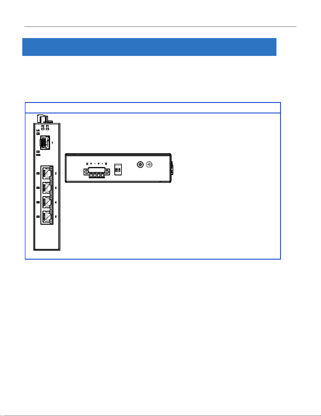
5-Port Series
2. Overview
RGS Series industrial Ethernet solutions deliver high quality, wide operation temperature range, extended
power input range and advanced VLAN & QoS features. It’s ideal for harsh environments and mission
critical applications.
2.1 Faceplate
10
Page 11
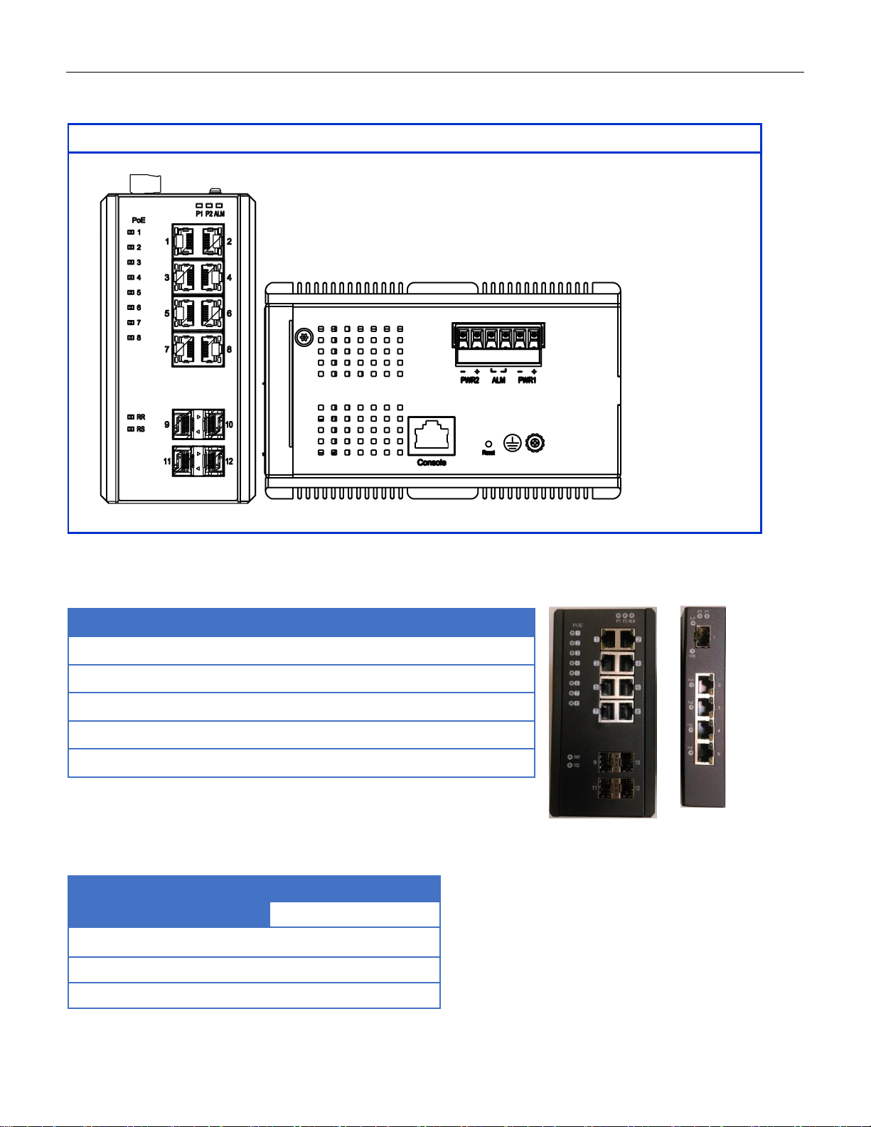
12-Port Series
Front Panel
System Status LED
P1, P2 and Alarm
Gigabit Ethernet Copper Ports
RJ45
Gigabit Ethernet SFP ports
SFP Slots
POE LED
POE port status
RR/RS LED
Device info/status
Models
L2+ Managed Switch
RGS200-12P
Total Gigabit Ethernet
Ports
12
10/100/1000 BaseT(X)
8
100/1000 Base SFP
4
2.2 Front Panel Introduction
11
Page 12
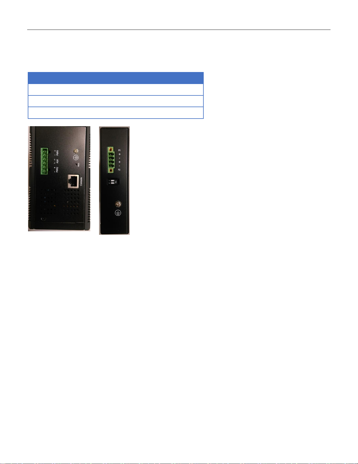
Top Panel
Power Input (Dual)
6P Terminal Block
Console (RS232)
RJ45
Reset
Push Button
2.3 Top Panel Introduction
12
Page 13

Quick Installation
Equipment Mounting
Cable Connecting
Equipment Configuration
13
Page 14
3.Quick Installation
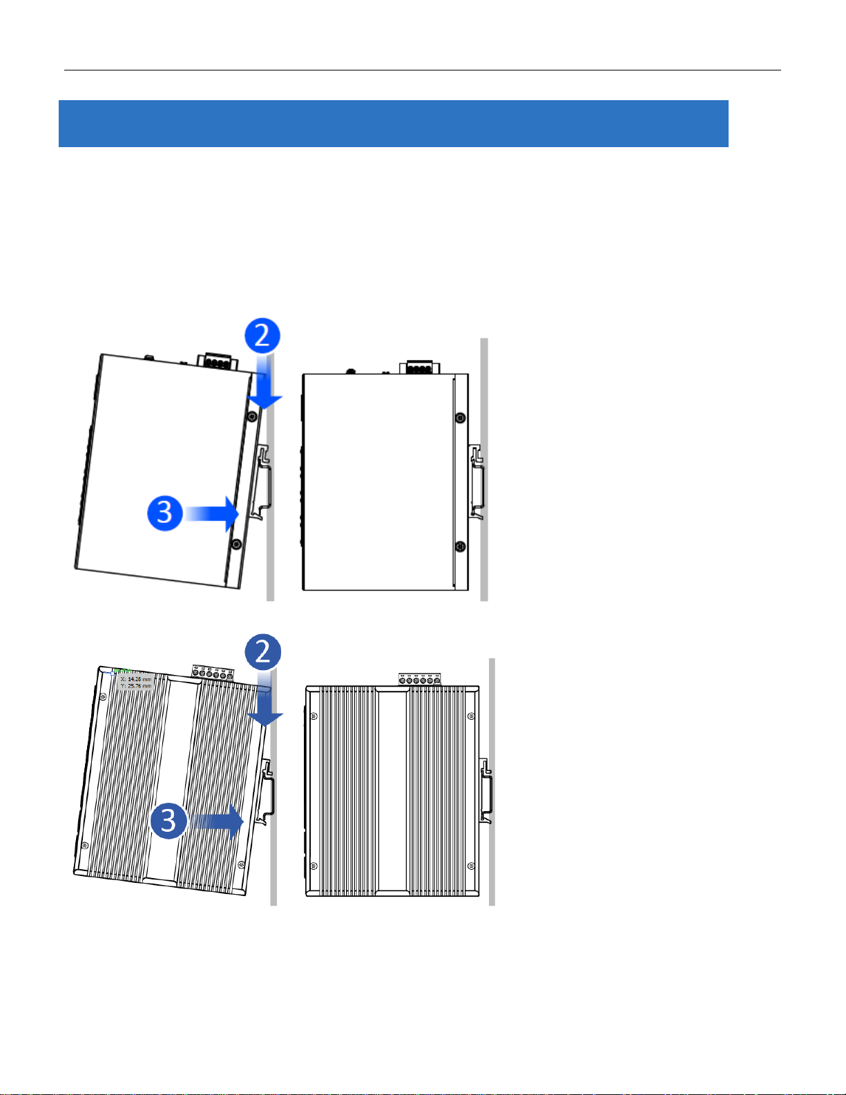
3.1 Mounting the RGS Series (DIN-Rail)
Mounting step:
1. Screw the DIN-Rail bracket on with the bracket and screws in the accessory kit.
2. Hook the unit over the DIN rail.
3. Push the bottom of the unit towards the DIN Rail until it snaps into place.
Figure 1 RGS100-5P DIN-Rail Mounting
Figure 2 RGS200-12P DIN-Rail Mounting
14
Page 15
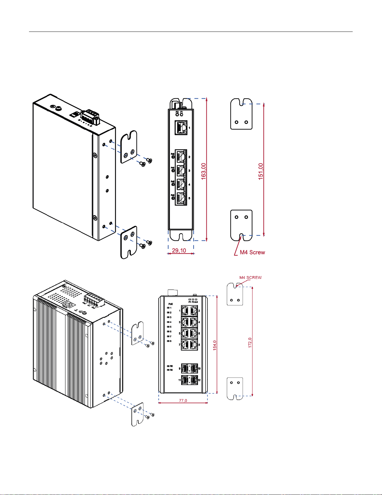
3.2 Mounting the RGS Series (Wall mount)
Mounting step:
1. Screw on the wall-mounting plate on with the plate and screws in the accessory kit.
Figure 3 RGS100-5P Series Wall Mounting
Figure 4 RGS200-12P Series Wall Mounting
15
Page 16
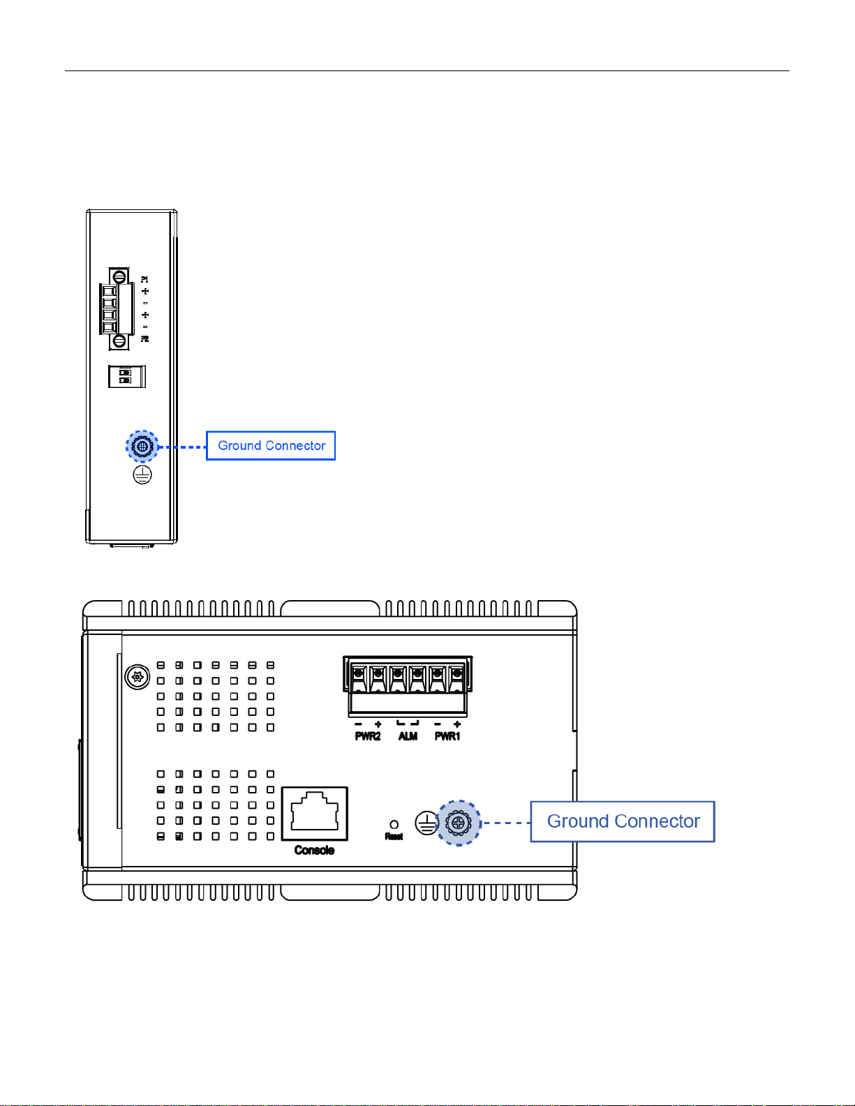
3.3 Ground Connections
RGS Series must be properly grounded for optimum system performance.
Figure 5 RGS100-5P Series Ground Connections
Figure 6 RGS200-12P Series Ground Connections
16
Page 17
Pin
Assignment
PoE
Assignment
1,2
T/Rx+,T/Rx-
Positive V
Port
3,6
T/Rx+,T/Rx-
Negative V
Port
4,5
T/Rx+,T/Rx-
X
7,8
T/Rx+,T/Rx-
X
Pin
Assignment
1,2
T/Rx+,T/Rx-
3,6
T/Rx+,T/Rx-
4,5
T/Rx+,T/Rx-
7,8
T/Rx+,T/Rx-
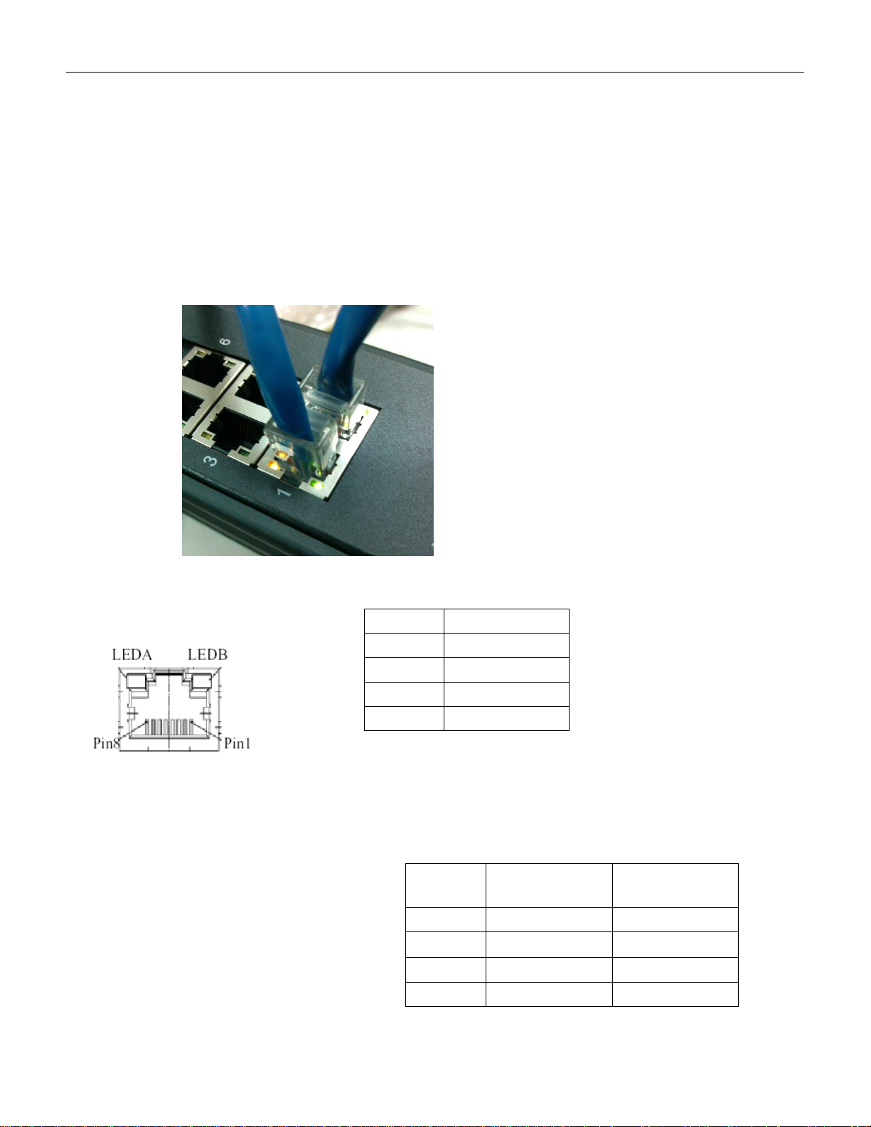
3.4 Connecting the Ethernet Interface (RJ45 Ethernet)
The switch provides two types of Ethernet interfaces: electrical (RJ45) and optical (SFP) interfaces.
Connecting the Ethernet interface via RJ45:
To connect the switch to a PC, use straight-through or cross-over Ethernet cables.
To connect the switch to an Ethernet device, use UTP (Unshielded Twisted Pair) or STP (Shielded Twisted
Pair) Ethernet cables.
The pin assignment of RJ-45 connector is shown in the following figure and table.
The pin assignment of RJ-45 connector is shown in the following figure and table.
RGS Series
RGS200-12P series
17
Page 18
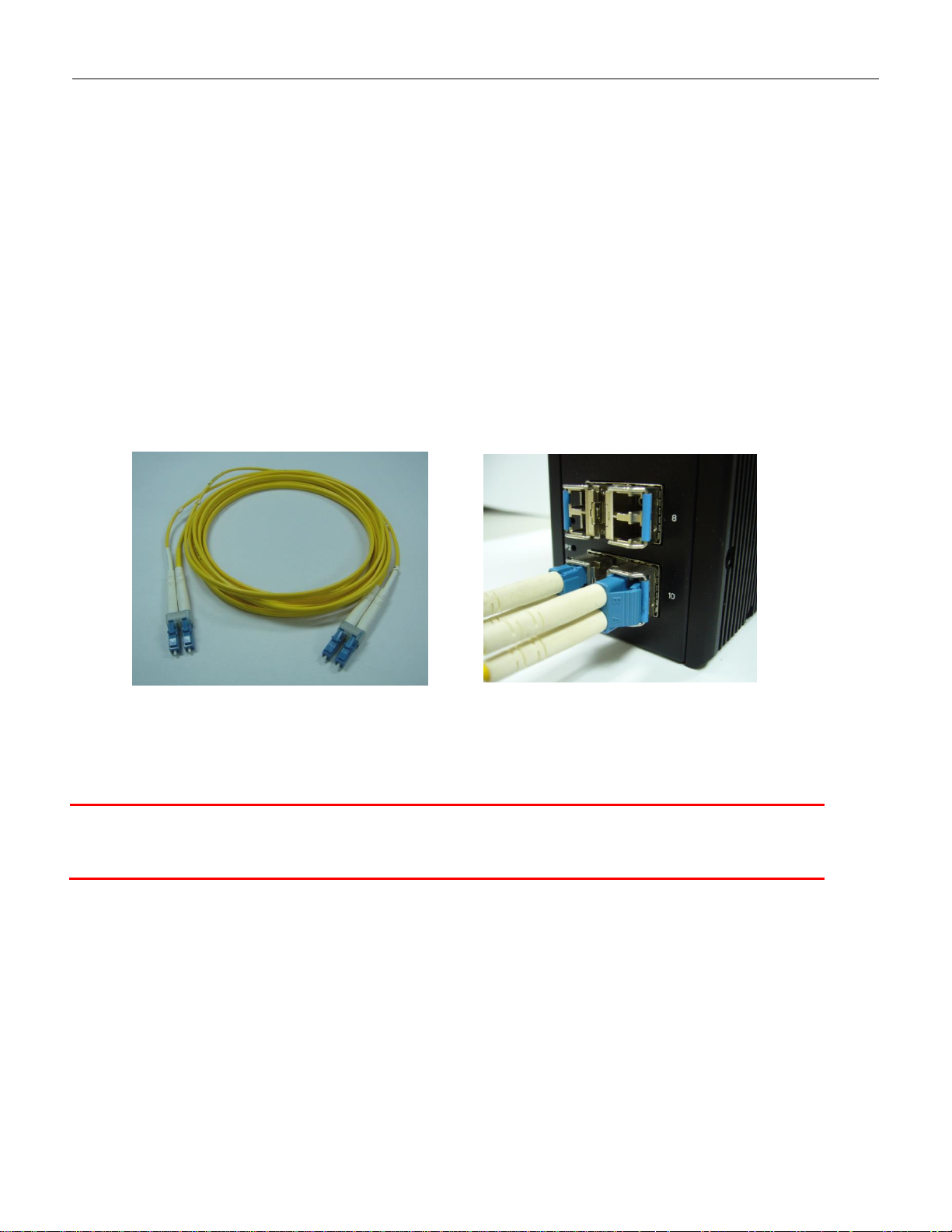
Fiber optics cable with LC duplex
connector
Connect the optical fiber to the SFP
socket
DANGER:
Never attempt to view optical connectors that might be emitting laser energy.
Do not power up the laser product without connecting the laser to the optical fiber and
putting the cover in position, as laser outputs will emit infrared laser light at this point.
3.5 Connecting the Ethernet Interface (Fiber)
Prepare a proper SFP module and install it into the optical port. Then you can connect fiber optics cabling
that uses LC connectors or SC connectors (with the use of an optional SC-to-LC adapter) to the fiber optics
connector. For a 100 Mbps fiber port available, please prepare the LC connectors or SC connectors (with the use of
an optional SC-to-LC adapter). They are also available with multimode, single mode, long-haul (for connections up to
120+ km) or special-application transceivers.
For a 1000 Mbps fiber port available, please use the mini-GBIC SFP (small form pluggable). These accept plug in
fiber transceivers that typically have an LC style connector. They are available with multimode, single mode, long-haul
(for connections up to 80+ km) or special-application transceivers.
For each fiber port there is a transmit (TX) and receive (RX) signal. Please make sure that the transmit (TX) port of
the switch connects to the receiver (RX) port of the other device, and the receive (RX) port of the switch connects to
the transmit (TX) port of the other device when making your fiber optic connections.
Refer to Table 1 for the normal operational LED status.
18
Page 19
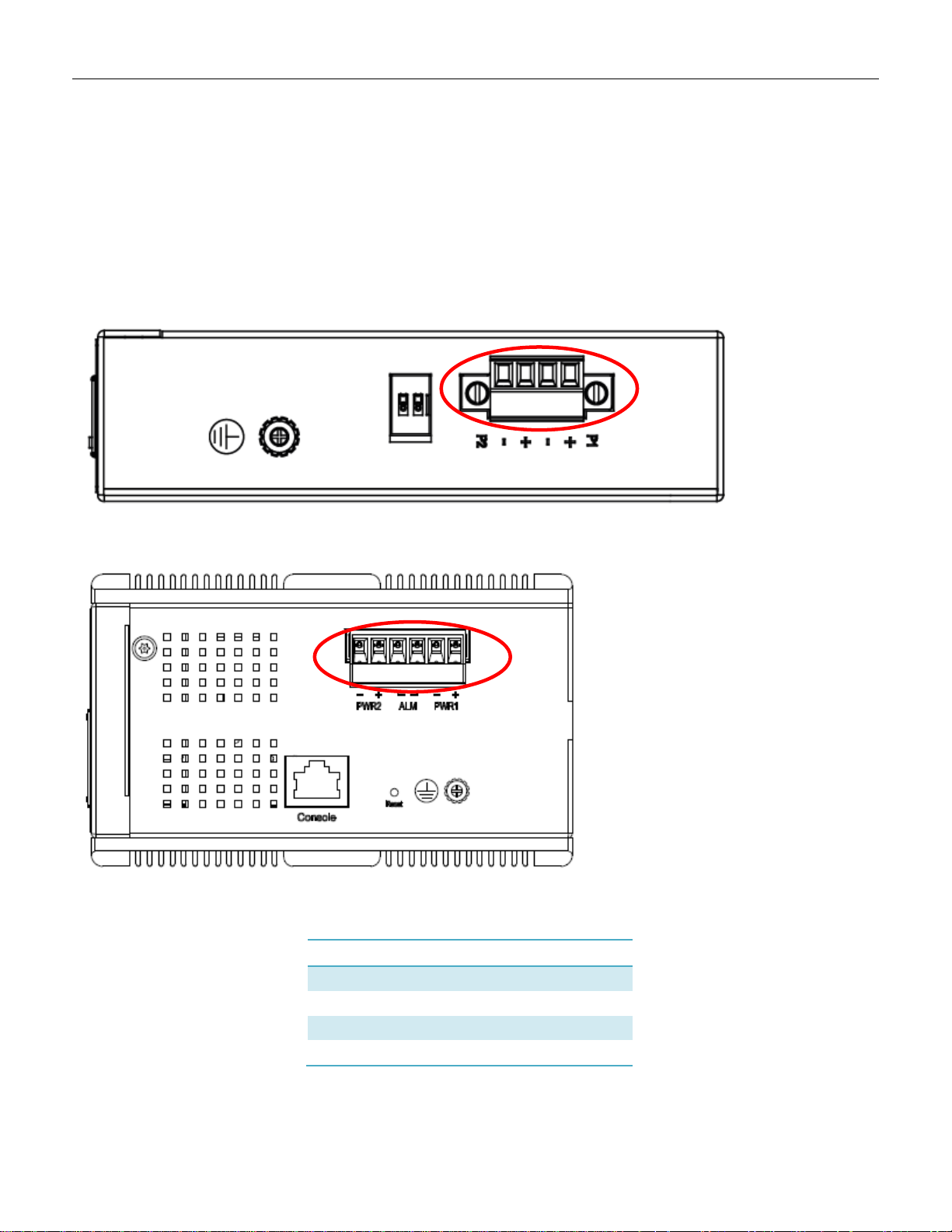
Power Connector (6P Terminal Block)
Input
DC 12-58V
PWR1 +/-
Power Input 1 +/-
PWR2 +/-
Power Input 2 +/-
ALM
Alarm relay output
3.6 Power Connection
The DC power interface is a 6-pin terminal block with polarity signs on the top panel.
The RGS200-12P can be powered from two power supply (input range 12V – 58V). The DC power
connector is a 6-pin terminal block; there is alarm contact on the middle terminal block.
Refer to Table 1 for the normal operational LED status.
Figure 7 RGS100-5P Series Power Connections
Figure 8 RGS200-12P Series Ground Connections
19
Page 20
Note:
1. The DC power should be connected to a well-fused power supply.
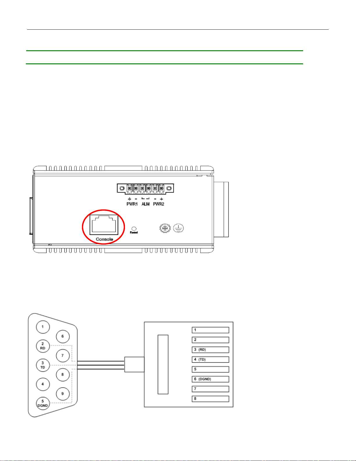
3.7 Console Connection
The Console port is for local management by using a terminal emulator or a computer with terminal
emulation software.
DB9 connector connect to computer COM port
Baud rate: 115200bps
8 data bits, 1 stop bit
None parity
None flow control
Figure 10 RGS200-12P Series Ground Connections
To connect the host PC to the console port, a RJ45 (male) connector-to-RS232 DB9 (female) connector
cable is required. The RJ45 connector of the cable is connected to the CID port of RGS200-12P; the DB9
connector of the cable is connected to the PC COM port. The pin assignment of the console cable is shown
below:
20
Page 21
Language script
Latin based
Web page font
Times New Roman
Plain text font
Courier New
Encoding
Unicode (UTF-8)
Text size
Medium
Web page font
Times New Roman
Encoding
Unicode (UTF-8)
Text size
16
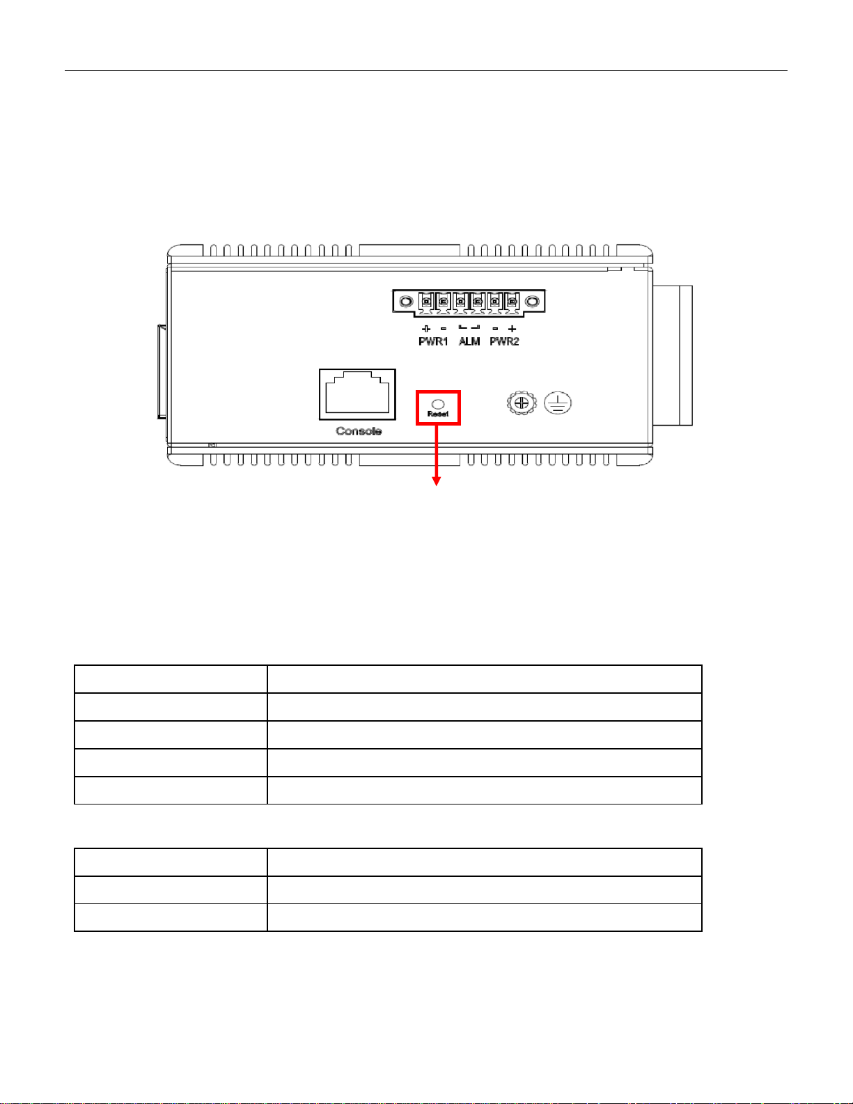
Reset Button
3.8 System Reset
The Reset button is provided to reboot the system without the need to remove power. Under normal
circumstances, you will not have to use it. However, or rare occasions, the RGS200-12P may not respond;
then you may need to push the Reset button.
3.9 Web Interface Initialization (Optional)
Web Browser Support
IE 7 (or newer version) with the following default settings is recommended:
Firefox with the following default settings is recommended:
21
Page 22

Web page font
Times New Roman
Encoding
Unicode (UTF-8)
Text size
Medium
Google Chrome with the following default settings is recommended:
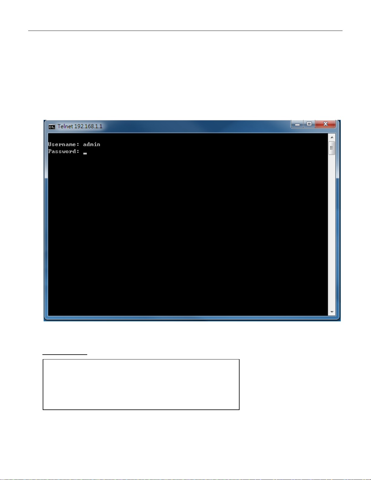
Connect and Login to RGS200-12P
1. Connecting to RGS200-12P Ethernet port (RJ45 Ethernet port).
2. Factory default IP: 192.168.1.1
3. Login with default account and password.
Username: admin
Password: 1234
22
Page 23
enable
configure terminal
interface vlan 1
ip address xxx.xxx.xxx.xxx xxx.xxx.xxx.xxx
exit
3.10 CLI Initialization and Configuration (Optional)
1. Connecting to RGS200-12P Ethernet port(RJ45 Ethernet port)
2. Key-in the command under Telnet: telnet 192.168.1.1
3. Login with default account and password.
Username: admin
Password: 1234
4. Change the IP with commands listed below:
CLI Command:
23
Page 24
3.11 Monitoring the Ethernet Interface
By RJ45 Ethernet:
Refer to Figure 11 LED Indicators for monitoring 8 Gigabit Ethernet with copper connector (RJ45). Also
refer toTable 1 for the normal operational LED status.
By SFP:
Refer to Figure 11 LED Indicators for monitoring 4 Gigabit Ethernet with SFP connector. Also refer to
Table 1 for the normal operational LED status.
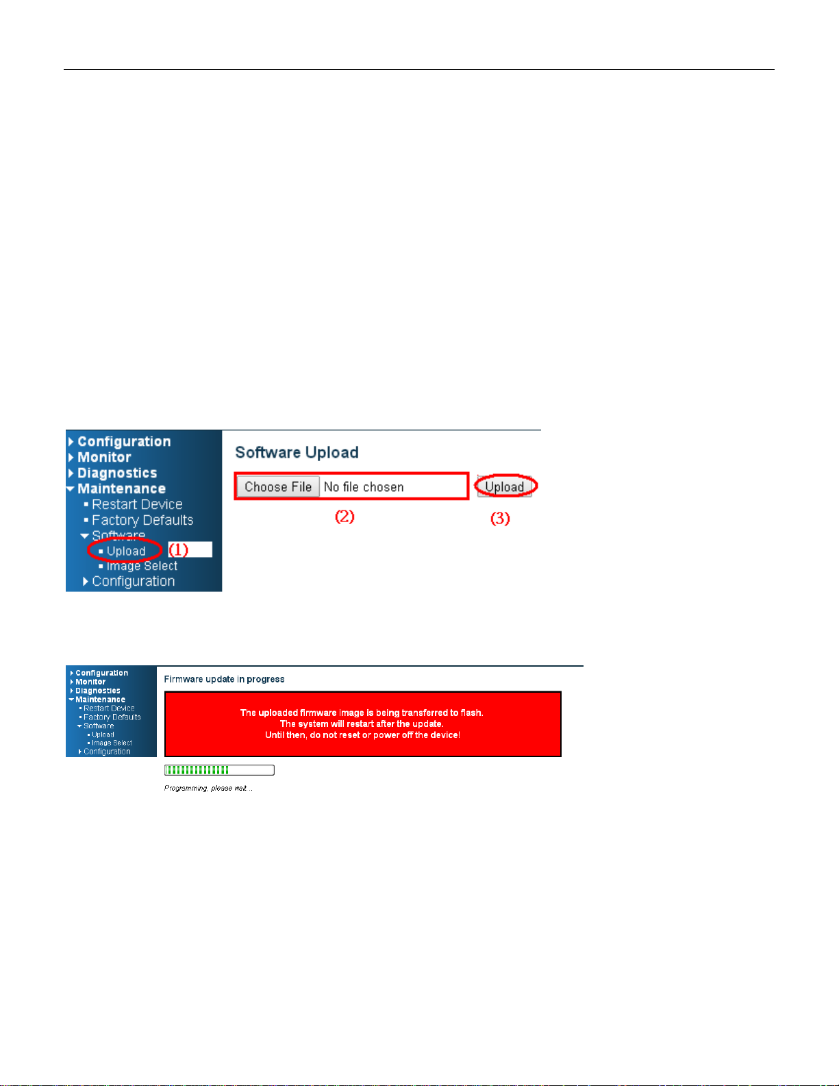
3.12 Upgrade Software
1. In Web UI, go to “MaintenanceSoftwareUpload” page.
2. Select software file, and click “Upload” button.
3. After starting to upload software to device, please don’t cold/warm start device and wait it auto reboot,
then upgrade finished.
24
Page 25
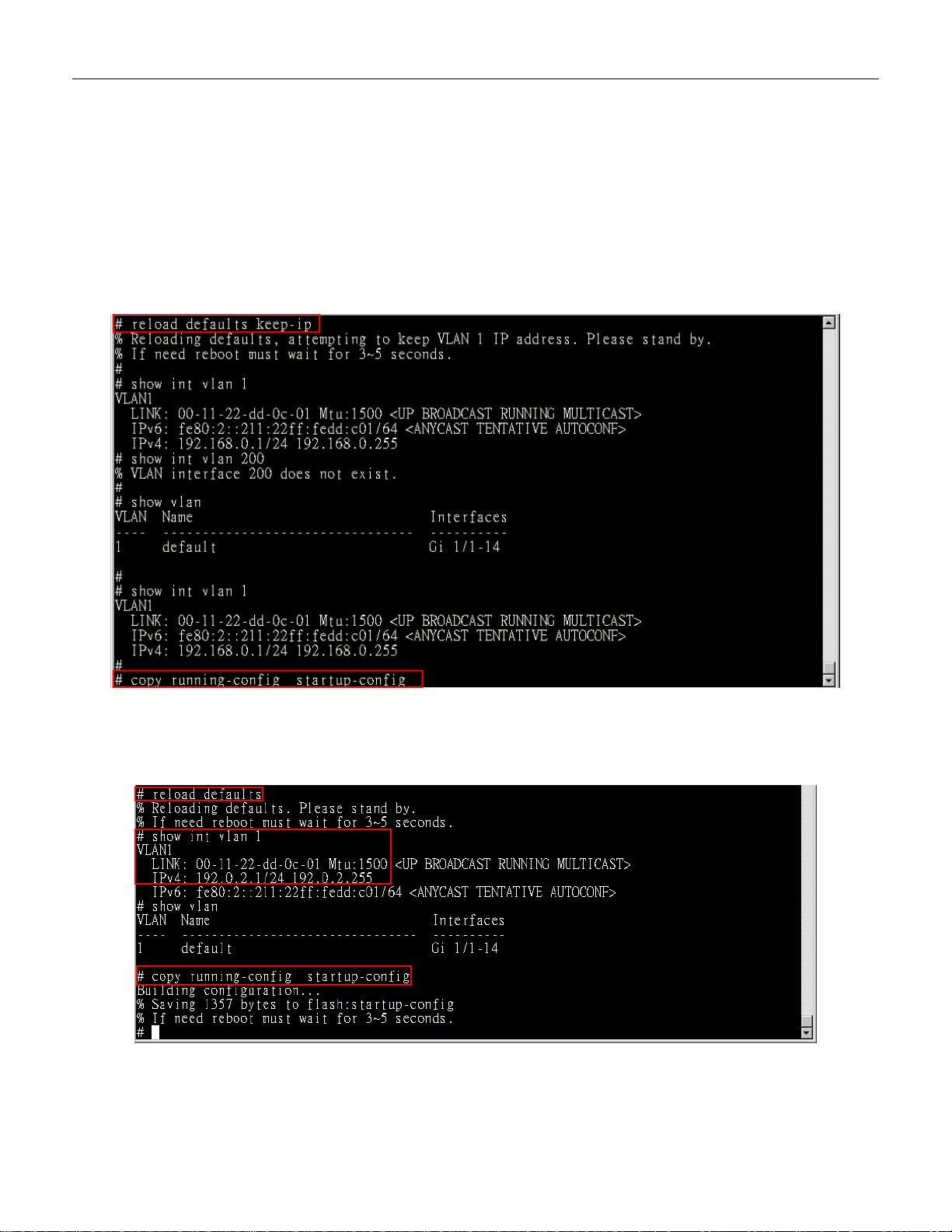
3.13 Reset to Default and Save Configure
Configuration via CLI command
To see what current interface and IP address is:
If the manager wants to reset the configuration to default, but keep management IP setting.
(1) Please execute this command: reload defaults keep-ip
(2) Check interface VLAN and IP address; confirm only management IP setting kept.
(3) Execute this command: copy running-config startup-config
If manager want to reset the all configuration to default completely
(1) Please execute this command: reload defaults
(2) Check interface VLAN and IP address, confirm they all change to default setting.
(3) Execute this command: copy running-config startup-config
25
Page 26
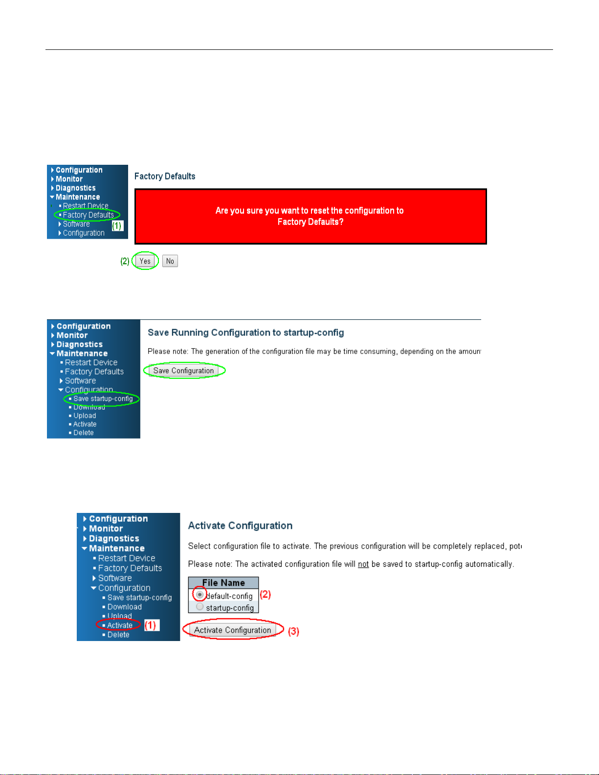
Configuration via WEB UI
If manager want to reset the configuration to default but keep management IP setting
(1)Go to “Maintenance””Factory Defaults” pagination to Click “Yes” button.
(2) Go to “Maintenance” “Configuration””Save startup-config” pagination, then click “Save
Configuration” button, then reset successfully
.
If manager want to reset the all configuration to default completely
(1) Go to “Maintenance” “Configuration””Activate” pagination to select “default-config”, then click
“Activate Configuration” button
26
Page 27
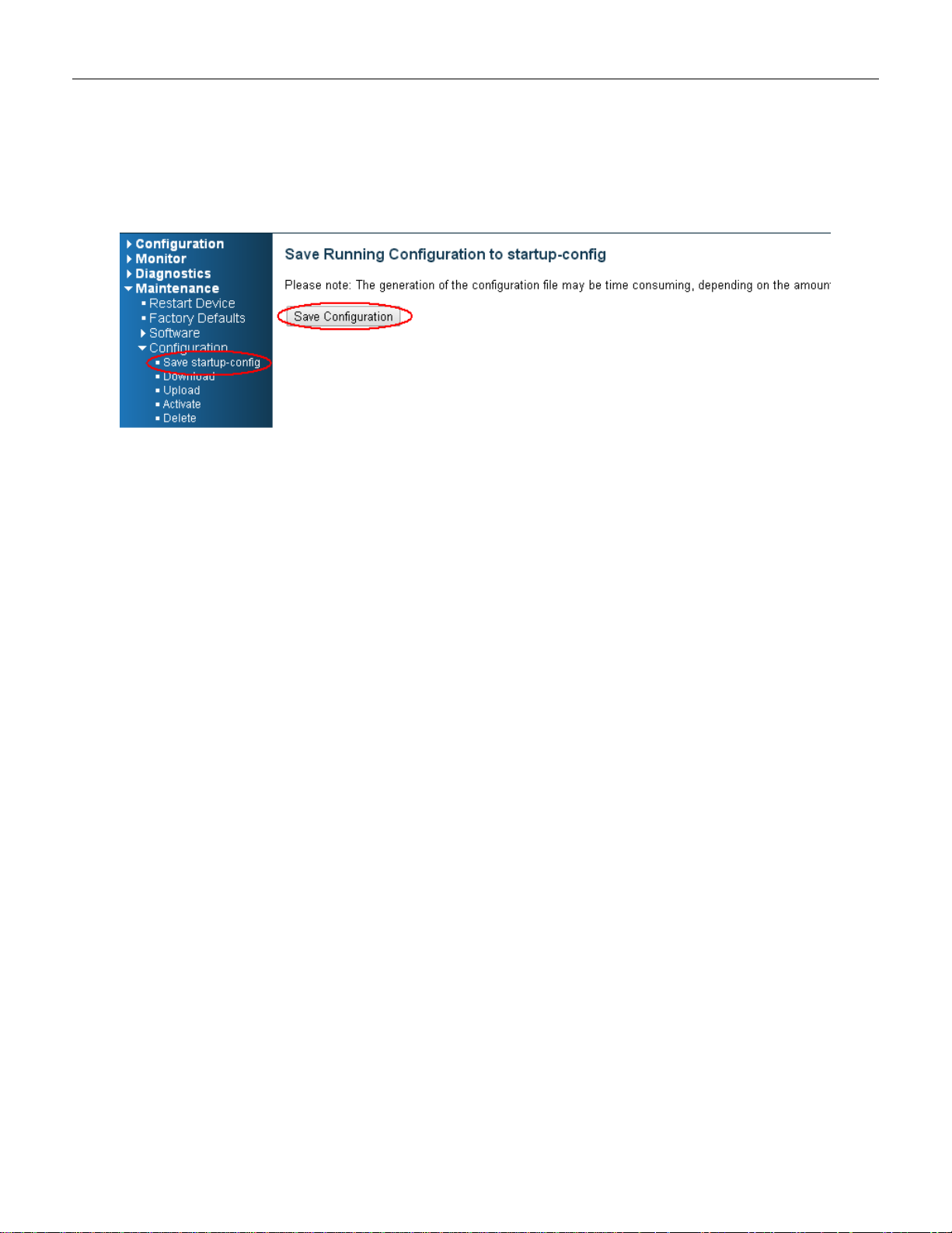
(2) Change WEB’s IP be 192.0.2.1(default IP) to login DUT’s Web UI.
(3) Go to “Maintenance” “Configuration””Save startup-config” pagination, then click “Save
Configuration” button, then reset successfully.
27
Page 28

Pin No#
Status
5-Port (4TX+1SFP) with PoE
Pin 1
ON
To enable Broadcast storm rate limit
OFF
To disable Broadcast storm rate limit
Pin 2
ON
NOT USED
OFF
NOT USED
LED
Name
Indicator
/color
Condition
P1/P2
On Green
P1/P2 power line has power
Off
P1/P2 power line disconnect or does not have power supplied
Alarm
On Red
Ethernet link fails, alarm or power failure alarm occurs
Off
No Ethernet link fails and no power failure alarm
Copper
port
Link/Act
On Green
Ethernet link up but no traffic is detected
Flashing
Green
Ethernet link up and there is traffic detected
Off
Ethernet link down
Copper
port
Speed
On Yellow
A 1000Mbps connection is detected
Off
No link, a 10Mbps or 100 Mbps connection is detected
SFP
port
Link/A
ct
On Green
Ethernet link up
Off
Ethernet link down
SFP
port
Speed
On Yellow
SFP port speed 1000Mbps connection is detected.
Off
No link or a SFP port speed 100Mbps connection is detected
POE
On Green
POE is working
Off
POE is not working
3.14 DIP Switch Setting for RGS100-5P
3.15 LED Status Indications
Table 1 LED Status Indicators
28
Page 29
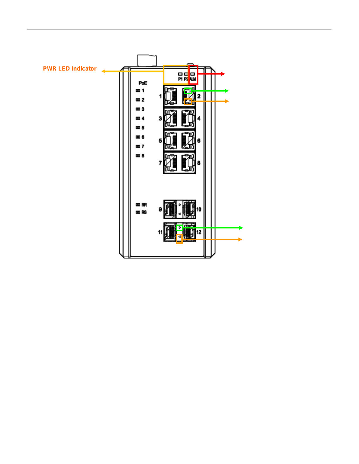
ALM LED Indicator
Copper Speed LED
Copper Link/Act LED
SFP Speed LED
Indicator
SFP Link LED Indicator
PWR LED Indicator
Figure 11 LED Indicators
29
Page 30
Language script
Latin based
Web page font
Times New Roman
Plain text font
Courier New
Encoding
Unicode (UTF-8)
Text size
Medium
Web page font
Times New Roman
Encoding
Unicode (UTF-8)
Text size
16
Web page font
Times New Roman
Encoding
Unicode (UTF-8)
4. Introduction
Note: The following web user guide is for RGS200-12P model.
4.1 System Description
RGS Series delivers high quality, wide operating temperature range, extended power input range, IP-30
design, and advanced VLAN & QoS features. It’s ideal for harsh environments and mission critical
applications.
RGS Series Managed QoS provides enterprise-class networking features to fulfill the needs of large
network infrastructure and extreme environments.
RGS Series eases the effort to build a network infrastructure which offers a reliable, well managed and
good QoS networking for any business requiring continuous and well-protected services in management
environments. With the features such as Fast Failover ring protection and QoS, customers can ensure
their network is qualified to deliver any real-time and high quality applications.
4.2 Using the Web Interface
The object of this document “RGS Web Configuration Tool Guide” is to address the web feature, design
layout and descript how to use the web interface.
4.2.1 Web Browser Support
IE 7 (or newer version) with the following default settings is recommended:
Firefox with the following default settings is recommended:
Google Chrome with the following default settings is recommended:
30
Page 31

Text size
Medium
4.2.2 Navigation
All main screens of the web interface can be reached by clicking on hyperlinks in the four menu boxes on
the left side of the screen:
Configuration
Monitor
Diagnostics
Maintenance
4.2.3 Title Bar Icons
Help Button
For more information about any screen, click on the Help button on the screen.
Help information is displayed in the same window.
Apply Button
Click Apply to apply the configuration changes to the device.
4.2.4 Ending a Session
To end a session, close your web browser. This prevents an unauthorized user from accessing the system
using your user name and password.
31
Page 32

4.3 Using the Online Help
Each screen has a Help button that invokes a page of information relevant to the particular screen. The
Help is displayed in a new window.
Each web page of Configuration/Status/System functions has a corresponding help page.
32
Page 33

5. Using the Web
Operation
1. Fill Username and Password
2. Click “Sign in”
Field
Description
Username
Login user name. The maximum length is 32.
Default: admin
Password
Login user password. The maximum length is 32.
Default: none
5.1 Login
5.2 Tree View
The tree view is a menu of the web. It offers user quickly to get the page for expected data or configuration.
33
Page 34

5.2.1 Configuration Menu
34
Page 35

5.2.2 Monitor Menu
35
Page 36

5.2.3 Diagnostics Menu
5.2.4 Maintenance Menu
36
Page 37

Object
Description
System Contact
The textual identification of the contact person for this managed node, together with
information on how to contact this person. The allowed string length is 0 to 255, and
the allowed content is the ASCII characters from 32 to 126.
System Name
An administratively assigned name for this managed node. By convention, this is the
node's fully-qualified domain name. A domain name is a text string drawn from the
alphabet (A-Za-z), digits (0-9), minus sign (-). No space characters are permitted as
part of a name. The first character must be an alpha character. And the first or last
character must not be a minus sign. The allowed string length is 0 to 255.
System Location
The physical location of this node (e.g., telephone closet, 3rd floor). The allowed
string length is 0 to 255, and the allowed content is the ASCII characters from 32 to
126.
Buttons
Click to apply changes.
Click to revert to previously saved values.
5.3 Configuration
5.3.1 System Information
The switch system information is provided here.
37
Page 38

Object
Description
IP Configuration
DNS Server
This setting controls the DNS name resolution done by the switch. The
following modes are supported:
From any DHCP interfaces
The first DNS server offered from a DHCP lease to a
DHCP-enabled interface will be used.
No DNS server
No DNS server will be used.
Configured
Explicitly provide the IP address of the DNS Server in dotted
decimal notation.
From this DHCP interface
Specify from which DHCP-enabled interface a provided DNS
server should be preferred.
DNS Proxy
When DNS proxy is enabled, system will relay DNS requests to the currently
configured DNS server, and reply as a DNS resolver to the client devices on the
network.
IP Interfaces
Delete
Select this option to delete an existing IP interface.
5.3.2 System IP
Configure IP basic settings, control IP interfaces and IP routes.
The maximum number of interfaces supported is 8 and the maximum number of routes is 32.
38
Page 39

VLAN
The VLAN associated with the IP interface. Only ports in this VLAN will be able to
access the IP interface. This field is only available for input when creating a new
interface.
IPv4 DHCP Enabled
Enable the DHCP client by checking this box. If this option is enabled, the system
will configure the IPv4 address and mask of the interface using the DHCP protocol.
The DHCP client will announce the configured System Name as hostname to
provide DNS lookup.
IPv4 DHCP Fallback
Timeout
The number of seconds for trying to obtain a DHCP lease. After this period expires,
a configured IPv4 address will be used as IPv4 interface address. A value of zero
disables the fallback mechanism, such that DHCP will keep retrying until a valid
lease is obtained. Legal values are 0 to 4294967295 seconds.
IPv4 DHCP Current Lease
For DHCP interfaces with an active lease, this column shows the current interface
address, as provided by the DHCP server.
IPv4 Address
The IPv4 address of the interface in dotted decimal notation.
If DHCP is enabled, this field configures the fallback address. The field may be left
blank if IPv4 operation on the interface is not desired - or no DHCP fallback address
is desired.
IPv4 Mask
The IPv4 network mask, in number of bits (prefix length). Valid values are between 0
and 30 bits for an IPv4 address.
If DHCP is enabled, this field configures the fallback address network mask. The field
may be left blank if IPv4 operation on the interface is not desired - or no DHCP
fallback address is desired.
IPv6 Address
The IPv6 address of the interface. An IPv6 address is in 128-bit records represented
as eight fields of up to four hexadecimal digits with a colon separating each field (:).
For example, fe80::215:c5ff:fe03:4dc7. The symbol :: is a special syntax
that can be used as a shorthand way of representing multiple 16-bit groups of
contiguous zeros; but it can appear only once. It can also represent a legally valid
IPv4 address. For example, ::192.1.2.34.
The field may be left blank if IPv6 operation on the interface is not desired.
IPv6 Mask
The IPv6 network mask, in number of bits (prefix length). Valid values are between 1
and 128 bits for an IPv6 address.
The field may be left blank if IPv6 operation on the interface is not desired.
IP Routes
Delete
Select this option to delete an existing IP route.
Network
The destination IP network or host address of this route. Valid format is notation
or a valid IPv6 notation. A default route can use the value 0.0.0.0or IPv6 ::
notation.
Mask Length
The destination IP network or host mask, in number of bits (prefix length). It defines
how much of a network address that must match, in order to qualify for this route.
Valid values are between 0 and 32 bits respectively 128 for IPv6 routes. Only a
default route will have a mask length of 0 (as it will match anything).
Gateway
The IP address of the IP gateway. Valid format is notation or a valid IPv6 notation.
Gateway and Network must be of the same type.
Next Hop VLAN(Only for
IPv6)
The VLAN ID (VID) of the specific IPv6 interface associated with the gateway.
The given VID ranges from 1 to 4094 and will be effective only when the
corresponding IPv6 interface is valid.
If the IPv6 gateway address is link-local, it must specify the next hop VLAN for the
gateway.
If the IPv6 gateway address is not link-local, system ignores the next hop VLAN for
the gateway.
Buttons
Click to add a new IP interface. A maximum of 8 interfaces is supported.
Click to add a new IP route. A maximum of 32 routes is supported.
39
Page 40

Click to apply changes.
Click to revert to previously saved values.
Object
Description
Mode
Indicates the NTP mode operation. Possible modes are:
Enabled: Enable NTP client mode operation.
Disabled: Disable NTP client mode operation.
Server #
Provide the IPv4 or IPv6 address of a NTP server. IPv6 address is in 128-bit records
represented as eight fields of up to four hexadecimal digits with a colon separating
each field (:). For example, 'fe80::215:c5ff:fe03:4dc7'. The symbol '::' is a special
syntax that can be used as a shorthand way of representing multiple 16-bit groups of
contiguous zeros; but it can appear only once. It can also represent a legally valid
IPv4 address. For example, '::192.1.2.34'.
Buttons
Click to apply changes.
Click to undo any changes made locally and revert to previously saved values.
5.3.3 System NTP
Configure NTP on this page.
5.3.4 System Time
This page allows you to configure the Time Zone.
40
Page 41

Object
Description
Time Zone Configuration
Time Zone
Lists various Time Zones worldwide. Select appropriate Time Zone from the drop
down and click Save to set.
Acronym
User can set the acronym of the time zone. This is a User configurable acronym to
identify the time zone. ( Range : Up to 16 characters )
41
Page 42

Daylight Saving Time Configuration
Daylight Saving Time
This is used to set the clock forward or backward according to the configurations set
below for a defined Daylight Saving Time duration. Select 'Disable' to disable the
Daylight Saving Time configuration. Select 'Recurring' and configure the Daylight
Saving Time duration to repeat the configuration every year. Select 'Non-Recurring'
and configure the Daylight Saving Time duration for single time configuration.
( Default : Disabled )
Recurring Configurations
Start time settings
Week
Select the starting week number.
Day
Select the starting day.
Month
Select the starting month.
Hours
Select the starting hour.
Minutes
Select the starting minute
End time settings
Week
Select the ending week number.
Day
Select the ending day.
Month
Select the ending month.
Hours
Select the ending hour.
Minutes
Select the ending minute
Offset settings
Offset
Enter the number of minutes to add during Daylight Saving Time. ( Range: 1 to 1440 )
Non Recurring Configurations
Start time settings
Month
Select the starting month.
Date
Select the starting date.
Year
Select the starting year.
Hours
Select the starting hour.
Minutes
Select the starting minute
End time settings
Month
Select the ending month.
Date
Select the ending date.
Year
Select the ending year.
Hours
Select the ending hour.
Minutes
Select the ending minute
Offset settings
Offset
Enter the number of minutes to add during Daylight Saving Time. ( Range: 1 to 1440 )
Date/Time Configuration
Date/Time Settings
Year
Year of current datetime. ( Range: 2000 to 2037 )
Month
Month of current datetime.
Date
Date of current datetime.
Hours
Hour of current datetime.
Minutes
Minute of current datetime.
Seconds
Second of current datetime.
Buttons
Click to apply changes.
Click to undo any changes made locally and revert to previously saved values.
42
Page 43

Object
Description
Server Mode
Indicates the server mode operation. When the mode operation is enabled, the syslog
message will send out to syslog server. The syslog protocol is based on UDP
communication and received on UDP port 514 and the syslog server will not send
acknowledgments back sender since UDP is a connectionless protocol and it does
not provide acknowledgments. The syslog packet will always send out even if the
syslog server does not exist. Possible modes are:
Enabled: Enable server mode operation.
Disabled: Disable server mode operation.
Server Address
Indicates the IPv4 host address of syslog server. If the switch provide DNS feature, it
also can be a host name.
Syslog Level
Indicates what kind of message will send to syslog server. Possible modes are:
Info: Send information, warnings and errors.
Warning: Send warnings and errors.
Error: Send errors.
Buttons
Click to apply changes.
Click to undo any changes made locally and revert to previously saved values.
5.3.5 System Log
Configure System Log on this page.
5.3.6 System Alarm Profile
Alarm Profile is provided here to enable/disable alarm.
43
Page 44

Object
Description
ID
The identification of the Alarm Profile entry.
Description
Alarm Type Description.
Enabled
If alarm entry is Enabled, then alarm will be shown in alarm history/current when it
occurs.
Alarm LED will be on (lighted), Alarm Relay also be enabled.
SNMP trap will be sent if any SNMP trap entry exists and enabled.
Disabled
If alarm entry is Disabled, then alarm will not be captured/shown in alarm
history/current when alarm occurs;
then it will not trigger the Alarm LED change, Alarm Relay and SNMP trap either.
Note: When any alarm exists, the Alarm LED will be on (lighted), Alarm Output Relay will also be
enabled.
Buttons
Click to apply changes.
Click to undo any changes made locally and revert to previously saved values.
44
Page 45

Object
Description
Port Power Savings Configuration
Optimize EEE for
The switch can be set to optimize EEE for either best power saving or least
traffic latency.
Port Configuration
Port
The switch port number of the logical port.
ActiPHY
Link down power savings enabled.
ActiPHY works by lowering the power for a port when there is no link. The port is
power up for short moment in order to determine if cable is inserted.
PerfectReach
Cable length power savings enabled.
PerfectReach works by determining the cable length and lowering the power for ports
with short cables.
5.3.7 EEE – Port Power Savings
This page allows the user to configure the port power savings features.
45
Page 46

EEE
Controls whether EEE is enabled for this switch port.
For maximizing power savings, the circuit isn't started at once transmit data is ready
for a port, but is instead queued until a burst of data is ready to be transmitted. This
will give some traffic latency.
If desired it is possible to minimize the latency for specific frames, by mapping the
frames to a specific queue (done with QOS), and then mark the queue as an urgent
queue. When an urgent queue gets data to be transmitted, the circuits will be
powered up at once and the latency will be reduced to the wakeup time.
EEE Urgent Queues
Queues set will activate transmission of frames as soon as data is available.
Otherwise the queue will postpone transmission until a burst of frames can be
transmitted.
Buttons
Click to apply changes.
Click to undo any changes made locally and revert to previously saved values.
46
Page 47

Object
Description
Port
This is the logical port number for this row.
Link
The current link state is displayed graphically. Green indicates the link is up and red
that it is down.
Current Link Speed
Provides the current link speed of the port.
Configured Link Speed
Selects any available link speed for the given switch port. Only speeds supported by
the specific port are shown. Possible speeds are:
Disabled - Disables the switch port operation.
Auto - Port auto negotiating speed with the link partner and selects the highest speed
that is compatible with the link partner.
10Mbps HDX - Forces the cu port in 10Mbps half duplex mode.
10Mbps FDX - Forces the cu port in 10Mbps full duplex mode.
100Mbps HDX - Forces the cu port in 100Mbps half duplex mode.
100Mbps FDX - Forces the cu port in 100Mbps full duplex mode.
1Gbps FDX - Forces the port in 1Gbps full duplex.
Flow Control
When Auto Speed is selected on a port, this section indicates the flow control
capability that is advertised to the link partner.
When a fixed-speed setting is selected, that is what is used. The Current Rx column
indicates whether pause frames on the port are obeyed, and the Current Tx column
indicates whether pause frames on the port are transmitted. The Rx and Tx settings
are determined by the result of the last Auto-Negotiation.
Check the configured column to use flow control. This setting is related to the setting
for Configured Link Speed.
Maximum Frame Size
Enter the maximum frame size allowed for the switch port, including FCS.
Excessive Collision
Mode
Configure port transmit collision behavior.
Discard: Discard frame after 16 collisions (default).
Restart: Restart backoff algorithm after 16 collisions.
5.3.8 Port
This page displays current port configurations. Ports can also be configured here.
47
Page 48

Buttons
Click to apply changes.
Click to undo any changes made locally and revert to previously saved values.
Click to refresh the page. Any changes made locally will be undone.
5.3.9 DHCP Snooping
Configure DHCP Snooping on this page.
48
Page 49

Object
Description
Snooping Mode
Indicates the DHCP snooping mode operation. Possible modes are:
Enabled: Enable DHCP snooping mode operation. When DHCP snooping mode
operation is enabled, the DHCP requests messages will be forwarded to trusted ports
and only allow reply packets from trusted ports.
Disabled: Disable DHCP snooping mode operation.
Port Mode Configuration
Indicates the DHCP snooping port mode. Possible port modes are:
Trusted: Configures the port as trusted source of the DHCP messages.
Untrusted: Configures the port as untrusted source of the DHCP messages.
Buttons
Click to apply changes.
Click to undo any changes made locally and revert to previously saved values.
Object
Description
Relay Mode
Indicates the DHCP relay mode operation.
Possible modes are:
Enabled: Enable DHCP relay mode operation. When DHCP relay mode operation is
enabled, the agent forwards and transfers DHCP messages between the clients and
the server when they are not in the same subnet domain. And the DHCP broadcast
message won't be flooded for security considerations.
Disabled: Disable DHCP relay mode operation.
Relay Server
Indicates the DHCP relay server IP address.
Relay Information Mode
Indicates the DHCP relay information mode option operation. The option 82 circuit ID
format as "[vlan_id][module_id][port_no]". The first four characters represent the
VLAN ID, the fifth and sixth characters are the module ID (in standalone device it
always equal 0, in stackable device it means switch ID), and the last two characters
are the port number. For example, "00030108" means the DHCP message receives
form VLAN ID 3, switch ID 1, port No 8. And the option 82 remote ID value is equal the
switch MAC address.
5.3.10 DHCP Relay
A DHCP relay agent is used to forward and to transfer DHCP messages between the clients and the server
when they are not in the same subnet domain. It stores the incoming interface IP address in the GIADDR field of
the DHCP packet. The DHCP server can use the value of GIADDR field to determine the assigned subnet. For
such condition, please make sure the switch configuration of VLAN interface IP address and PVID (Port VLAN
ID) correctly.
49
Page 50

Possible modes are:
Enabled: Enable DHCP relay information mode operation. When DHCP relay
information mode operation is enabled, the agent inserts specific information (option
82) into a DHCP message when forwarding to DHCP server and removes it from a
DHCP message when transferring to DHCP client. It only works when DHCP relay
operation mode is enabled.
Disabled: Disable DHCP relay information mode operation.
Relay Information Policy
Indicates the DHCP relay information option policy. When DHCP relay information
mode operation is enabled, if the agent receives a DHCP message that already
contains relay agent information it will enforce the policy. The 'Replace' policy is
invalid when relay information mode is disabled. Possible policies are:
Keep: Keep the original relay information when a DHCP message that already
contains it is received.
Buttons
Click to apply changes.
Click to undo any changes made locally and revert to previously saved values.
50
Page 51

Object
Description
User Name
A string identifying the user name that this entry should belong to. The allowed string
length is 1 to 31. The valid user name allows letters, numbers and underscores.
Password
The password of the user. The allowed string length is 0 to 31. Any printable
characters including space are accepted.
Privilege Level
The privilege level of the user. The allowed range is 1 to 15. If the privilege level value
is 15, it can access all groups, i.e. that is granted the fully control of the device. But
others value need to refer to each group privilege level. User's privilege should be
same or greater than the group privilege level to have the access of that group. By
default setting, most group privilege level 5 has the read-only access and privilege
level 10 has the read-write access. And the system maintenance (software upload,
factory defaults and etc.) need user privilege level 15. Generally, the privilege level 15
can be used for an administrator account, privilege level 10 for a standard user
account and privilege level 5 for a guest account.
Buttons
Click to add a new user.
Click to apply changes.
Click to undo any changes made locally and revert to previously saved values.
Click to undo any changes made locally and return to the Users.
Delete the current user. This button is not available for new configurations
(Add new user)
5.3.11 Security – Switch Users
This page provides an overview of the current users. Currently the only way to login as another user on the web
server is to close and reopen the browser.
51
Page 52

5.3.12 Privilege Level
This page provides an overview of the privilege levels.
52
Page 53

Object
Description
Group Name
The name identifying the privilege group. In most cases, a privilege level group
consists of a single module (e.g. LACP, RSTP or QoS), but a few of them contains
more than one. The following description defines these privilege level groups in
details:
System: Contact, Name, Location, Timezone, Daylight Saving Time, Log.
Security: Authentication, System Access Management, Port (contains Dot1x port,
MAC based and the MAC Address Limit), ACL, HTTPS, SSH, ARP Inspection, IP
source guard.
IP: Everything except 'ping'.
Port: Everything except 'VeriPHY'.
Diagnostics: 'ping' and 'VeriPHY'.
Maintenance: CLI- System Reboot, System Restore Default, System Password,
Configuration Save, Configuration Load and Firmware Load. Web- Users, Privilege
Levels and everything in Maintenance.
Debug: Only present in CLI.
Privilege Levels
Every group has an authorization Privilege level for the following sub groups:
configuration read-only, configuration/execute read-write, status/statistics read-only,
status/statistics read-write (e.g. for clearing of statistics). User Privilege should be
same or greater than the authorization Privilege level to have the access to that
group.
Buttons
Click to apply changes.
Click to undo any changes made locally and revert to previously saved values.
53
Page 54

Object
Description
Client
The management client for which the configuration below applies.
Methods
Method can be set to one of the following values:
no: Authentication is disabled and login is not possible.
local: Use the local user database on the switch for authentication.
radius: Use remote RADIUS server(s) for authentication.
tacacs+: Use remote TACACS+ server(s) for authentication.
Methods that involve remote servers are timed out if the remote servers are offline. In
this case the next method is tried. Each method is tried from left to right and continues
until a method either approves or rejects a user. If a remote server is used for primary
authentication it is recommended to configure secondary authentication as 'local'.
This will enable the management client to login via the local user database if none of
the configured authentication servers are alive.
Buttons
Click to apply changes.
Click to undo any changes made locally and revert to previously saved values.
5.3.13 Authentication Method
This page allows you to configure how a user is authenticated when he logs into the switch via one of the
management client interfaces.
54
Page 55

Object
Description
Mode
Indicates the SSH mode operation. Possible modes are:
Enabled: Enable SSH mode operation.
Disabled: Disable SSH mode operation.
Buttons
Click to apply changes.
Click to undo any changes made locally and revert to previously saved values.
5.3.14 SSH
Configure SSH on this page.
55
Page 56

Object
Description
Mode
Indicates the HTTPS mode operation. When the current connection is HTTPS, to
apply HTTPS disabled mode operation will automatically redirect web browser to an
HTTP connection. Possible modes are:
Enabled: Enable HTTPS mode operation.
Disabled: Disable HTTPS mode operation.
Automatic Redirect
Indicates the HTTPS redirect mode operation. It only significant if HTTPS mode
"Enabled" is selected. Automatically redirects web browser to an HTTPS connection
when both HTTPS mode and Automatic Redirect are enabled. Possible modes are:
Enabled: Enable HTTPS redirect mode operation.
Disabled: Disable HTTPS redirect mode operation.
Buttons
Click to apply changes.
Click to undo any changes made locally and revert to previously saved values.
5.3.15 HTTPS
Configure HTTPS on this page.
56
Page 57

Object
Description
Mode
Indicates the access management mode operation. Possible modes are:
Enabled: Enable access management mode operation.
Disabled: Disable access management mode operation.
Delete
Check to delete the entry. It will be deleted during the next save.
VLAN ID
Indicates the VLAN ID for the access management entry.
Start IP address
Indicates the start IP address for the access management entry.
End IP address
Indicates the end IP address for the access management entry.
HTTP/HTTPS
Indicates that the host can access the switch from HTTP/HTTPS interface if the host
IP address matches the IP address range provided in the entry.
SNMP
Indicates that the host can access the switch from SNMP interface if the host IP
address matches the IP address range provided in the entry.
TELNET/SSH
Indicates that the host can access the switch from TELNET/SSH interface if the host
IP address matches the IP address range provided in the entry.
Buttons
Click to add a new access management entry.
Click to apply changes.
Click to undo any changes made locally and revert to previously saved values.
5.3.16 Access Management
Configure access management table on this page. The maximum number of entries is 16. If the application's
type matches any one of the access management entries, it will allow access to the switch.
57
Page 58

Object
Description
Mode
Indicates the SNMP mode operation. Possible modes are:
Enabled: Enable SNMP mode operation.
Disabled: Disable SNMP mode operation.
Version
Indicates the SNMP supported version. Possible versions are:
SNMP v1: Set SNMP supported version 1.
SNMP v2c: Set SNMP supported version 2c.
SNMP v3: Set SNMP supported version 3.
Read Community
Indicates the community read access string to permit access to SNMP agent. The
allowed string length is 0 to 255, and the allowed content is the ASCII characters from
33 to 126.
The field is applicable only when SNMP version is SNMPv1 or SNMPv2c. If SNMP
version is SNMPv3, the community string will be associated with SNMPv3
communities table. It provides more flexibility to configure security name than a
SNMPv1 or SNMPv2c community string. In addition to community string, a particular
range of source addresses can be used to restrict source subnet.
Write Community
Indicates the community writes access string to permit access to SNMP agent. The
allowed string length is 0 to 255, and the allowed content is the ASCII characters from
33 to 126.
The field is applicable only when SNMP version is SNMPv1 or SNMPv2c. If SNMP
version is SNMPv3, the community string will be associated with SNMPv3
communities table. It provides more flexibility to configure security name than a
SNMPv1 or SNMPv2c community string. In addition to community string, a particular
range of source addresses can be used to restrict source subnet.
Engine ID
Indicates the SNMPv3 engine ID. The string must contain an even number (in
hexadecimal format) with number of digits between 10 and 64, but all-zeros and
all-'F's are not allowed. Change of the Engine ID will clear all original local users.
5.3.17 SNMP System Configuration
Configure SNMP on this page.
58
Page 59

Buttons
Click to apply changes.
Click to undo any changes made locally and revert to previously saved values.
59
Page 60

Object
Description
Global Settings
Mode
Indicates the trap mode operation. Possible modes are:
Enabled: Enable SNMP trap mode operation.
Disabled: Disable SNMP trap mode operation.
Trap Destination Configurations
Name
Indicates the trap Configuration's name. Indicates the trap destination's name.
Enable
Indicates the trap destination mode operation. Possible modes are:
Enabled: Enable SNMP trap mode operation.
Disabled: Disable SNMP trap mode operation.
Version
Indicates the SNMP trap supported version. Possible versions are:
SNMPv1: Set SNMP trap supported version 1.
SNMPv2c: Set SNMP trap supported version 2c.
SNMPv3: Set SNMP trap supported version 3.
Destination Address
Indicates the SNMP trap destination address. It allows a valid IP address in dotted
decimal notation ('x.y.z.w').
And it also allows a valid hostname. A valid hostname is a string drawn from the
alphabet (A-Za-z), digits (0-9), dot (.), dash (-). Spaces are not allowed, the first
character must be an alpha character, and the first and last characters must not be a
dot or a dash.
Indicates the SNMP trap destination IPv6 address. IPv6 address is in 128-bit records
represented as eight fields of up to four hexadecimal digits with a colon separating
each field (:). For example, 'fe80::215:c5ff:fe03:4dc7'. The symbol '::' is a special
syntax that can be used as a shorthand way of representing multiple 16-bit groups of
contiguous zeros; but it can appear only once. It can also represent a legally valid
IPv4 address. For example, '::192.1.2.34'.
Destination port
Indicates the SNMP trap destination port. SNMP Agent will send SNMP message via
this port, the port range is 1~65535.
5.3.18 SNMP Trap Configuration
Configure SNMP trap on this page.
60
Page 61

Object
Description
Trap Mode
Indicates the SNMP trap mode operation. Possible modes are:
Enabled: Enable SNMP trap mode operation.
Disabled: Disable SNMP trap mode operation.
Trap Version
Indicates the SNMP trap supported version. Possible versions are:
SNMP v1: Set SNMP trap supported version 1.
SNMP v2c: Set SNMP trap supported version 2c.
SNMP v3: Set SNMP trap supported version 3.
Trap Community
Indicates the community access string when sending SNMP trap packet. The allowed
string length is 0 to 255, and the allowed content is ASCII characters from 33 to 126.
Trap Destination
Address
Indicates the SNMP trap destination address. It allows a valid IP address in dotted
decimal notation ('x.y.z.w').
And it also allows a valid hostname. A valid hostname is a string drawn from the
alphabet (A-Za-z), digits (0-9), dot (.), dash (-). Spaces are not allowed, the first
character must be an alpha character, and the first and last characters must not be a
dot or a dash
Trap Destination IIPv6
Address
Indicates the SNMP trap destination IPv6 address. IPv6 address is in 128-bit records
represented as eight fields of up to four hexadecimal digits with a colon separating
The SNMP Trap Configuration page includes the following fields:
61
Page 62

each field (:). For example, 'fe80::215:c5ff:fe03:4dc7'. The symbol '::' is a special
syntax that can be used as a shorthand way of representing multiple 16-bit groups of
contiguous zeros; but it can appear only once. It can also represent a legally valid
IPv4 address. For example, '::192.1.2.34'.
Trap Authentication
Failure
Indicates that the SNMP entity is permitted to generate authentication failure traps.
Possible modes are:
Enabled: Enable SNMP trap authentication failure.
Disabled: Disable SNMP trap authentication failure.
Trap Link-up and
Link-down
Indicates the SNMP trap link-up and link-down mode operation. Possible modes are:
Enabled: Enable SNMP trap link-up and link-down mode operation.
Disabled: Disable SNMP trap link-up and link-down mode operation.
Trap Inform Mode
Indicates the SNMP trap inform mode operation. Possible modes are:
Enabled: Enable SNMP trap inform mode operation.
Disabled: Disable SNMP trap inform mode operation.
Trap Inform Timeout
(seconds)
Indicates the SNMP trap inform timeout. The allowed range is 0 to 2147.
Trap Inform Retry Times
Indicates the SNMP trap informs retry times. The allowed range is 0 to 255.
Trap Probe Security
Engine ID
Indicates the SNMP trap probe security engine ID mode of operation. Possible values
are:
Enabled: Enable SNMP trap probe security engine ID mode of operation.
Disabled: Disable SNMP trap probe security engine ID mode of operation.
Trap Security Engine ID
Indicates the SNMP trap security engine ID. SNMPv3 sends traps and informs using
USM for authentication and privacy. A unique engine ID for these traps and informs is
needed. When "Trap Probe Security Engine ID" is enabled, the ID will be probed
automatically. Otherwise, the ID specified in this field is used. The string must contain
an even number (in hexadecimal format) with number of digits between 10 and 64,
but all-zeros and all-'F's are not allowed.
Trap Security Name
Indicates the SNMP trap security name. SNMPv3 traps and informs using USM for
authentication and privacy. A unique security name is needed when traps and informs
are enabled.
Buttons
Click to add a new user.
Click to apply changes.
Click to undo any changes made locally and revert to previously saved values.
62
Page 63

Object
Description
Delete
Check to delete the entry. It will be deleted during the next save.
Community
Indicates the community access string to permit access to SNMPv3 agent. The
allowed string length is 1 to 32, and the allowed content is ASCII characters from 33 to
126. The community string will be treated as security name and map a SNMPv1 or
SNMPv2c community string.
Source IP
Indicates the SNMP access source address. A particular range of source addresses
can be used to restrict source subnet when combined with source mask.
Source Mask
Indicates the SNMP access source address mask.
Buttons
Click to add a new community entry.
Click to apply changes.
Click to undo any changes made locally and revert to previously saved values.
5.3.19 SNMP Communities
Configure SNMPv3 community table on this page. The entry index key is Community.
63
Page 64

Object
Description
Delete
Check to delete the entry. It will be deleted during the next save.
Engine ID
An octet string identifying the engine ID that this entry should belong to. The string
must contain an even number (in hexadecimal format) with number of digits between
10 and 64, but all-zeros and all-'F's are not allowed. The SNMPv3 architecture uses
the User-based Security Model (USM) for message security and the View-based
Access Control Model (VACM) for access control. For the USM entry, the
usmUserEngineID and usmUserName are the entry's keys. In a simple agent,
usmUserEngineID is always that agent's own snmpEngineID value. The value can
also take the value of the snmpEngineID of a remote SNMP engine with which this
user can communicate. In other words, if user engine ID equal system engine ID then
it is local user; otherwise it's remote user.
User name
A string identifying the user name that this entry should belong to. The allowed string
length is 1 to 32, and the allowed content is ASCII characters from 33 to 126.
Security Level
Indicates the security model that this entry should belong to. Possible security models
are:
NoAuth, NoPriv: No authentication and no privacy.
Auth, NoPriv: Authentication and no privacy.
Auth, Priv: Authentication and privacy.
The value of security level cannot be modified if entry already exists. That means it
must first be ensured that the value is set correctly.
Authentication Protocol
Indicates the authentication protocol that this entry should belong to. Possible
authentication protocols are:
None: No authentication protocol.
MD5: An optional flag to indicate that this user uses MD5 authentication protocol.
SHA: An optional flag to indicate that this user uses SHA authentication protocol.
The value of security level cannot be modified if entry already exists. That means
must first ensure that the value is set correctly.
Authentication
Password
A string identifying the authentication password phrase. For MD5 authentication
protocol, the allowed string length is 8 to 32. For SHA authentication protocol, the
allowed string length is 8 to 40. The allowed content is ASCII characters from 33 to
126.
Privacy Protocol
Indicates the privacy protocol that this entry should belong to. Possible privacy
protocols are:
None: No privacy protocol.
DES: An optional flag to indicate that this user uses DES authentication protocol.
AES: An optional flag to indicate that this user uses AES authentication protocol.
Privacy Password
A string identifying the privacy password phrase. The allowed string length is 8 to 32,
and the allowed content is ASCII characters from 33 to 126.
5.3.20 SNMP Users
Configure SNMPv3 user table on this page. The entry index keys are Engine ID and User Name.
64
Page 65

Buttons
Click to add a new user entry.
Click to apply changes.
Click to undo any changes made locally and revert to previously saved values.
65
Page 66

Object
Description
Delete
Check to delete the entry. It will be deleted during the next save.
Security Model
Indicates the security model that this entry should belong to. Possible security models
are:
v1: Reserved for SNMPv1.
v2c: Reserved for SNMPv2c.
usm: User-based Security Model (USM).
Security Name
A string identifying the security name that this entry should belong to. The allowed
string length is 1 to 32, and the allowed content is ASCII characters from 33 to 126.
Group Name
A string identifying the group name that this entry should belong to. The allowed string
length is 1 to 32, and the allowed content is ASCII characters from 33 to 126.
Buttons
Click to add a new group entry
Click to apply changes.
Click to undo any changes made locally and revert to previously saved values.
5.3.21 SNMP Groups
Configure SNMPv3 group table on this page. The entry index keys are Security Model and Security Name.
66
Page 67

Object
Description
Delete
Check to delete the entry. It will be deleted during the next save.
View Name
A string identifying the view name that this entry should belong to. The allowed string
length is 1 to 32, and the allowed content is ASCII characters from 33 to 126.
View Type
Indicates the view type that this entry should belong to. Possible view types are:
included: An optional flag to indicate that this view subtree should be included.
excluded: An optional flag to indicate that this view subtree should be excluded.
In general, if a view entry's view type is 'excluded', there should be another view entry
existing with view type as 'included' and its OID subtree should overstep the
'excluded' view entry.
OID Subtree
The OID defining the root of the subtree to add to the named view. The allowed OID
length is 1 to 128. The allowed string content is digital number or asterisk(*).
Buttons
Click to add a new view entry.
Click to apply changes.
Click to undo any changes made locally and revert to previously saved values.
5.3.22 SNMP Views
Configure SNMPv3 view table on this page. The entry index keys are View Name and OID Subtree.
67
Page 68

Object
Description
Delete
Check to delete the entry. It will be deleted during the next save.
Group Name
A string identifying the group name that this entry should belong to. The allowed string
length is 1 to 32, and the allowed content is ASCII characters from 33 to 126.
Security Model
Indicates the security model that this entry should belong to. Possible security models
are:
any: Any security model accepted (v1|v2c|usm).
v1: Reserved for SNMPv1.
v2c: Reserved for SNMPv2c.
usm: User-based Security Model (USM).
Security Level
Indicates the security model that this entry should belong to. Possible security models
are:
NoAuth, NoPriv: No authentication and no privacy.
Auth, NoPriv: Authentication and no privacy.
Auth, Priv: Authentication and privacy.
Read View Name
The name of the MIB view defining the MIB objects for which this request may request
the current values. The allowed string length is 1 to 32, and the allowed content is
ASCII characters from 33 to 126.
Write View Name
The name of the MIB view defining the MIB objects for which this request may
potentially set new values. The allowed string length is 1 to 32, and the allowed
content is ASCII characters from 33 to 126.
Buttons
Click to add a new access entry.
Click to apply changes.
Click to undo any changes made locally and revert to previously saved values.
5.3.23 SNMP Access
Configure SNMPv3 access table on this page. The entry index keys are Group Name, Security Model and
Security Level.
68
Page 69

Object
Description
Delete
Check to delete the entry. It will be deleted during the next save.
ID
Indicates the index of the entry. The range is from 1 to 65535.
Data Source
Indicates the port ID which wants to be monitored. If in stacking switch, the value must
add 1000*(switch ID-1), for example, if the port is switch 3 port 5, the value is 2005
Buttons
Click to add a new community entry.
Click to apply changes.
Click to undo any changes made locally and revert to previously saved values.
5.3.25 RMON Statistics
Configure RMON Statistics table on this page. The entry index key is ID.
69
Page 70

Object
Description
Delete
Check to delete the entry. It will be deleted during the next save.
ID
Indicates the index of the entry. The range is from 1 to 65535.
Data Source
Indicates the port ID which wants to be monitored. If in stacking switch, the value must
add 1000*(switch ID-1), for example, if the port is switch 3 port 5, the value is 2005.
Interval
Indicates the interval in seconds for sampling the history statistics data. The range is
from 1 to 3600, default value is 1800 seconds.
Buckets
Indicates the maximum data entries associated this History control entry stored in
RMON. The range is from 1 to 3600, default value is 50.
Buckets Granted
The number of data shall be saved in the RMON.
Buttons
Click to add a new community entry.
Click to apply changes.
Click to undo any changes made locally and revert to previously saved values.
5.3.26 RMON History
Configure RMON History table on this page. The entry index key is ID.
70
Page 71

Object
Description
Delete
Check to delete the entry. It will be deleted during the next save.
ID
Indicates the index of the entry. The range is from 1 to 65
Interval
Indicates the interval in seconds for sampling and comparing the rising and falling
threshold. The range is from 1 to 2^31-1.
Variable
Indicates the particular variable to be sampled, the possible variables are:
InOctets: The total number of octets received on the interface, including framing
characters.
InUcastPkts: The number of uni-cast packets delivered to a higher-layer protocol.
InNUcastPkts: The number of broad-cast and multi-cast packets delivered to a
higher-layer protocol.
InDiscards: The number of inbound packets that are discarded even the packets
are normal.
InErrors: The number of inbound packets that contained errors preventing them
from being deliverable to a higher-layer protocol.
InUnknownProtos: the number of the inbound packets that were discarded
because of the unknown or un-support protocol.
OutOctets: The number of octets transmitted out of the interface , including framing
characters.
OutUcastPkts: The number of uni-cast packets that request to transmit.
OutNUcastPkts: The number of broad-cast and multi-cast packets that request to
transmit.
OutDiscards: The number of outbound packets that are discarded event the
packets are normal.
OutErrors: The number of outbound packets that could not be transmitted because
of errors.
OutQLen: The length of the output packet queue (in packets).
Sample Type
The method of sampling the selected variable and calculating the value to be
compared against the thresholds, possible sample types are:
Absolute: Get the sample directly.
Delta: Calculate the difference between samples (default).
Value
The value of the statistic during the last sampling period.
Startup Alarm
The method of sampling the selected variable and calculating the value to be
compared against the thresholds, possible sample types are:
RisingTrigger alarm when the first value is larger than the rising threshold.
FallingTrigger alarm when the first value is less than the falling threshold.
RisingOrFallingTrigger alarm when the first value is larger than the rising
threshold or less than the falling threshold (default).
Rising Threshold
Rising threshold value (-2147483648-2147483647).
Rising Index
Rising event index (1-65535).
Falling Threshold
Falling threshold value (-2147483648-2147483647)
Falling Index
Falling event index (1-65535).
5.3.27 RMON Alarm
Configure RMON Alarm table on this page. The entry index key is ID.
71
Page 72

Buttons
Click to add a new community entry.
Click to apply changes.
Click to undo any changes made locally and revert to previously saved values.
72
Page 73

Object
Description
Delete
Check to delete the entry. It will be deleted during the next save.
ID
Indicates the index of the entry. The range is from 1 to 65535.
Desc
Indicates this event, the string length is from 0 to 127, default is a null string.
Type
Indicates the notification of the event, the possible types are:
none: No SNMP log is created, no SNMP trap is sent.
log: Create SNMP log entry when the event is triggered.
snmptrap: Send SNMP trap when the event is triggered.
logandtrap: Create SNMP log entry and sent SNMP trap when the event is
triggered.
Community
Specify the community when trap is sent, the string length is from 0 to 127, default is
"public".
Event Last Time
Indicates the value of sysUpTime at the time this event entry last generated an event.
Buttons
Click to add a new community entry.
Click to apply changes.
Click to undo any changes made locally and revert to previously saved values.
5.3.28 RMON Event
Configure RMON Event table on this page. The entry index key is ID.
73
Page 74

Object
Description
System Configuration
Mode
Indicates if Limit Control is globally enabled or disabled on the switch. If globally
disabled, other modules may still use the underlying functionality, but limit checks and
corresponding actions are disabled.
Aging Enabled
If checked, secured MAC addresses are subject to aging as discussed under Aging
Period .
Aging Period
If Aging Enabled is checked, then the aging period is controlled with this input. If other
modules are using the underlying port security for securing MAC addresses, they may
have other requirements to the aging period. The underlying port security will use the
shorter requested aging period of all modules that use the functionality.
The Aging Period can be set to a number between 10 and 10,000,000 seconds.
To understand why aging may be desired, consider the following scenario: Suppose
5.3.29 Network – Limit Control
This page allows you to configure the Port Security Limit Control system and port settings.
Limit Control allows for limiting the number of users on a given port. A user is identified by a MAC address and
VLAN ID. If Limit Control is enabled on a port, the limit specifies the maximum number of users on the port. If
this number is exceeded, an action is taken. The action can be one of the four different actions as described
below.
The Limit Control module utilizes a lower-layer module, Port Security module, which manages MAC addresses
learnt on the port.
The Limit Control configuration consists of two sections, a system- and a port-wide.
74
Page 75

an end-host is connected to a 3rd party switch or hub, which in turn is connected to a
port on this switch on which Limit Control is enabled. The end-host will be allowed to
forward if the limit is not exceeded. Now suppose that the end-host logs off or powers
down. If it wasn't for aging, the end-host would still take up resources on this switch
and will be allowed to forward. To overcome this situation, enable aging. With aging
enabled, a timer is started once the end-host gets secured. When the timer expires,
the switch starts looking for frames from the end-host, and if such frames are not seen
within the next Aging Period, the end-host is assumed to be disconnected, and the
corresponding resources are freed on the switch.
Port Configuration
Port
The port number to which the configuration below applies.
Mode
Controls whether Limit Control is enabled on this port. Both this and the Global Mode
must be set to Enabled for Limit Control to be in effect. Notice that other modules may
still use the underlying port security features without enabling Limit Control on a given
port.
Limit
The maximum number of MAC addresses that can be secured on this port. This
number cannot exceed 1024. If the limit is exceeded, the corresponding action is
taken.
The switch is "born" with a total number of MAC addresses from which all ports draw
whenever a new MAC address is seen on a Port Security-enabled port. Since all ports
draw from the same pool, it may happen that a configured maximum cannot be
granted, if the remaining ports have already used all available MAC addresses.
Action
If Limit is reached, the switch can take one of the following actions:
None: Do not allow more than Limit MAC addresses on the port, but take no further
action.
Trap: If Limit + 1 MAC addresses are seen on the port, send an SNMP trap. If Aging
is disabled, only one SNMP trap will be sent, but with Aging enabled, new SNMP traps
will be sent every time the limit gets exceeded.
Shutdown: If Limit + 1 MAC addresses is seen on the port, shut down the port. This
implies that all secured MAC addresses will be removed from the port, and no new
address will be learned. Even if the link is physically disconnected and reconnected
on the port (by disconnecting the cable), the port will remain shut down. There are
three ways to re-open the port:
1) Boot the switch,
2) Disable and re-enable Limit Control on the port or the switch,
3) Click the Reopen button.
Trap & Shutdown: If Limit + 1 MAC addresses is seen on the port, both the "Trap"
and the "Shutdown" actions described above will be taken.
State
This column shows the current state of the port as seen from the Limit Control's point
of view. The state takes one of four values:
Disabled: Limit Control is either globally disabled or disabled on the port.
Ready: The limit is not yet reached. This can be shown for all actions.
Limit Reached: Indicates that the limit is reached on this port. This state can only be
shown if Action is set to None or Trap.
Shutdown: Indicates that the port is shut down by the Limit Control module. This
state can only be shown if Action is set to Shutdown or Trap & Shutdown.
Re-open Button
If a port is shutdown by this module, you may reopen it by clicking this button, which
will only be enabled if this is the case. For other methods, refer to Shutdown in the
Action section.
Note that clicking the reopen button causes the page to be refreshed, so
non-committed changes will be lost.
Buttons
75
Page 76

Click to refresh the page. Note that non-committed changes will be lost.
Click to apply changes.
Click to undo any changes made locally and revert to previously saved values.
76
Page 77

Object
Description
Port
The logical port for the settings contained in the same row.
Policy ID
Select the policy to apply to this port. The allowed values are 0 through 255. The
default value is 0.
Action
Select whether forwarding is permitted ("Permit") or denied ("Deny"). The default
value is "Permit".
Rate Limiter ID
Select which rate limiter to apply on this port. The allowed values are Disabled or
the values 1 through 16. The default value is "Disabled".
Port Redirect
Select which port frames are redirected on. The allowed values are Disabled or a
specific port number and it can't be set when action is permitted. The default value is
"Disabled".
Mirror
Specify the mirror operation of this port. The allowed values are:
Enabled: Frames received on the port are mirrored.
Disabled: Frames received on the port are not mirrored.
The default value is "Disabled".
Logging
Specify the logging operation of this port. Notice that the logging message doesn't
include the 4 bytes CRC. The allowed values are:
Enabled: Frames received on the port are stored in the System Log.
Disabled: Frames received on the port are not logged.
The default value is "Disabled". Note: The logging feature only works when the packet
length is less than 1518(without VLAN tags) and the System Log memory size and
logging rate is limited.
Shutdown
Specify the port shut down operation of this port. The allowed values are:
Enabled: If a frame is received on the port, the port will be disabled.
5.3.30 ACL – ACL Port
Configure the ACL parameters (ACE) of each switch port. These parameters will affect frames received on a port
unless the frame matches a specific ACE.
77
Page 78

Disabled: Port shut down is disabled.
The default value is "Disabled".
Note: The shutdown feature only works when the packet length is less than
1518(without VLAN tags).
State
Specify the port state of this port. The allowed values are:
Enabled: To reopen ports by changing the volatile port configuration of the ACL user
module.
Disabled: To close ports by changing the volatile port configuration of the ACL user
module.
The default value is "Enabled".
Counter
Counts the number of frames that match this ACE.
Buttons
Click to apply changes.
Click to undo any changes made locally and revert to previously saved values.
Click to refresh the page; any changes made locally will be undone.
Click to clear the counters.
5.3.31 ACL Rate Limiters
Configure the rate limiter for the ACL of the switch.
78
Page 79

Object
Description
Rate Limiter ID
The rate limiter ID for the settings contained in the same row.
Rate
The rate range is located 0-3276700 in pps.
Or 0, 100, 200, 300, ..., 1000000 in kbps.
Unit
Specify the rate unit. The allowed values are:
pps: packets per second.
kbps: Kbits per second.
Buttons
Click to apply changes.
Click to undo any changes made locally and revert to previously saved values.
79
Page 80

Object
Description
Ingress Port
Indicates the ingress port of the ACE. Possible values are:
All: The ACE will match all ingress port.
Port: The ACE will match a specific ingress port.
Policy / Bitmask
Indicates the policy number and bitmask of the ACE.
Frame Type
Indicates the frame type of the ACE. Possible values are:
Any: The ACE will match any frame type.
EType: The ACE will match Ethernet Type frames. Note that an Ethernet Type based
ACE will not get matched by IP and ARP frames.
ARP: The ACE will match ARP/RARP frames.
IPv4: The ACE will match all IPv4 frames.
IPv4/ICMP: The ACE will match IPv4 frames with ICMP protocol.
IPv4/UDP: The ACE will match IPv4 frames with UDP protocol.
IPv4/TCP: The ACE will match IPv4 frames with TCP protocol.
IPv4/Other: The ACE will match IPv4 frames, which are not ICMP/UDP/TCP.
IPv6: The ACE will match all IPv6 standard frames.
Action
Indicates the forwarding action of the ACE.
Permit: Frames matching the ACE may be forwarded and learned.
Deny: Frames matching the ACE are dropped.
Filter: Frames matching the ACE are filtered.
Rate Limiter
Indicates the rate limiter number of the ACE. The allowed range is 1 to 16. When
Disabled is displayed, the rate limiter operation is disabled.
Port Redirect
Indicates the port redirect operation of the ACE. Frames matching the ACE are
redirected to the port number. The allowed values are Disabled or a specific port
number. When Disabled is displayed, the port redirect operation is disabled.
Mirror
Specify the mirror operation of this port. Frames matching the ACE are mirrored to the
destination mirror port. The allowed values are:
Enabled: Frames received on the port are mirrored.
Disabled: Frames received on the port are not mirrored.
The default value is "Disabled".
Counter
The counter indicates the number of times the ACE was hit by a frame.
Modification Buttons
You can modify each ACE (Access Control Entry) in the table using the following
buttons:
: Inserts a new ACE before the current row.
: Edits the ACE row.
: Moves the ACE up the list.
: Moves the ACE down the list.
: Deletes the ACE.
: The lowest plus sign adds a new entry at the bottom of the ACE listings.
5.3.32 Access Control List
This page shows the Access Control List (ACL), which is made up of the ACEs defined on this switch. Each row
describes the ACE that is defined. The maximum number of ACEs is 256 on each switch.
Click on the lowest plus sign to add a new ACE to the list. The reserved ACEs used for internal protocol, cannot
be edited or deleted, the order sequence cannot be changed and the priority is highest.
80
Page 81

Buttons
Check this box to refresh the page automatically. Automatic refresh occurs every 3
seconds.
Click to refresh the page; any changes made locally will be undone.
Click to clear the counters.
Click to remove all ACEs.
Object
Description
Ingress Port
Select the ingress port for which this ACE applies.
All: The ACE applies to all port.
Port n: The ACE applies to this port number, where n is the number of the switch
port.
Policy Filter
Specify the policy number filter for this ACE.
Any: No policy filter is specified. (policy filter status is "don't-care".)
Specific: If you want to filter a specific policy with this ACE, choose this value. Two
field for entering a policy value and bitmask appears.
Policy Value
When "Specific" is selected for the policy filter, you can enter a specific policy value.
The allowed range is 0 to 255.
Policy Bitmask
When "Specific" is selected for the policy filter, you can enter a specific policy bitmask.
The allowed range is 0x0 to 0xff. Notice the usage of bitmask, if the binary bit value
is "0", it means this bit is "don't-care". The real matched pattern is [policy_value &
policy_bitmask]. For example, if the policy value is 3 and the policy bitmask is 0x10(bit
0 is "don't-care" bit), then policy 2 and 3 are applied to this rule.
Frame Type
Select the frame type for this ACE. These frame types are mutually exclusive.
Any: Any frame can match this ACE.
Ethernet Type: Only Ethernet Type frames can match this ACE. The IEEE 802.3
describes the value of Length/Type Field specifications to be greater than or equal to
1536 decimal (equal to 0600 hexadecimal).
The ACE Configuration page includes the following fields:
81
Page 82

ARP: Only ARP frames can match this ACE. Notice the ARP frames won't match the
ACE with Ethernet type.
IPv4: Only IPv4 frames can match this ACE. Notice the IPv4 frames won't match the
ACE with Ethernet type.
IPv6: Only IPv6 frames can match this ACE. Notice the IPv6 frames won't match the
ACE with Ethernet type.
Action
Specify the action to take with a frame that hits this ACE.
Permit: The frame that hits this ACE is granted permission for the ACE operation.
Deny: The frame that hits this ACE is dropped.
Filter: Frames matching the ACE are filtered.
Rate Limiter
Specify the rate limiter in number of base units. The allowed range is 1 to 16.
Disabled indicates that the rate limiter operation is disabled.
Port Redirect
Frames that hit the ACE are redirected to the port number specified here. The rate
limiter will affect these ports. The allowed range is the same as the switch port
number range. Disabled indicates that the port redirect operation is disabled and
the specific port number of 'Port Redirect' can't be set when action is permitted.
Mirror
Specify the mirror operation of this port. Frames matching the ACE are mirrored to the
destination mirror port. The rate limiter will not affect frames on the mirror port. The
allowed values are:
Enabled: Frames received on the port are mirrored.
Disabled: Frames received on the port are not mirrored.
The default value is "Disabled".
Logging
Specify the logging operation of the ACE. Notice that the logging message doesn't
include the 4 bytes CRC information. The allowed values are:
Enabled: Frames matching the ACE are stored in the System Log.
Disabled: Frames matching the ACE are not logged.
Note: The logging feature only works when the packet length is less than
1518(without VLAN tags) and the System Log memory size and logging rate is
limited.
Shutdown
Specify the port shut down operation of the ACE. The allowed values are:
Enabled: If a frame matches the ACE, the ingress port will be disabled.
Disabled: Port shut down is disabled for the ACE.
Note: The shutdown feature only works when the packet length is less than
1518(without VLAN tags).
Counter
The counter indicates the number of times the ACE was hit by a frame.
MAC Parameters
SMAC Filter
(Only displayed when the frame type is Ethernet Type or ARP.)
Specify the source MAC filter for this ACE.
Any: No SMAC filter is specified. (SMAC filter status is "don't-care".)
Specific: If you want to filter a specific source MAC address with this ACE, choose
this value. A field for entering an SMAC value appears.
SMAC Value
When "Specific" is selected for the SMAC filter, you can enter a specific source MAC
address. The legal format is "xx-xx-xx-xx-xx-xx" or "xx.xx.xx.xx.xx.xx" or
"xxxxxxxxxxxx" (x is a hexadecimal digit). A frame that hits this ACE matches this
SMAC value.
DMAC Filter
Specify the destination MAC filter for this ACE.
Any: No DMAC filter is specified. (DMAC filter status is "don't-care".)
MC: Frame must be multicast.
BC: Frame must be broadcast.
UC: Frame must be unicast.
Specific: If you want to filter a specific destination MAC address with this ACE,
choose this value. A field for entering a DMAC value appears.
DMAC Value
When "Specific" is selected for the DMAC filter, you can enter a specific destination
MAC address. The legal format is "xx-xx-xx-xx-xx-xx" or "xx.xx.xx.xx.xx.xx" or
"xxxxxxxxxxxx" (x is a hexadecimal digit). A frame that hits this ACE matches this
DMAC value.
VLAN Parameters
802.1Q Tagged
Specify whether frames can hit the action according to the 802.1Q tagged. The
82
Page 83

allowed values are:
Any: Any value is allowed ("don't-care").
Enabled: Tagged frame only.
Disabled: Untagged frame only.
The default value is "Any".
VLAN ID Filter
Specify the VLAN ID filter for this ACE.
Any: No VLAN ID filter is specified. (VLAN ID filter status is "don't-care".)
Specific: If you want to filter a specific VLAN ID with this ACE, choose this value. A
field for entering a VLAN ID number appears.
VLAN ID
When "Specific" is selected for the VLAN ID filter, you can enter a specific VLAN ID
number. The allowed range is 1 to 4095. A frame that hits this ACE matches this
VLAN ID value.
Tag Priority
Specify the tag priority for this ACE. A frame that hits this ACE matches this tag
priority. The allowed number range is 0 to 7 or range 0-1, 2-3, 4-5, 6-7, 0-3 and
4-7. The value Any means that no tag priority is specified (tag priority is "don't-care".)
ARP Parameters
ARP/RARP
Specify the available ARP/RARP opcode (OP) flag for this ACE.
Any: No ARP/RARP OP flag is specified. (OP is "don't-care".)
ARP: Frame must have ARP opcode set to ARP.
RARP: Frame must have RARP opcode set to RARP.
Other: Frame has unknown ARP/RARP Opcode flag.
Request/Reply
Specify the available Request/Reply opcode (OP) flag for this ACE.
Any: No Request/Reply OP flag is specified. (OP is "don't-care".)
Request: Frame must have ARP Request or RARP Request OP flag set.
Reply: Frame must have ARP Reply or RARP Reply OP flag.
Sender IP Filter
Specify the sender IP filter for this ACE.
Any: No sender IP filter is specified. (Sender IP filter is "don't-care".)
Host: Sender IP filter is set to Host. Specify the sender IP address in the SIP Address
field that appears.
Network: Sender IP filter is set to Network. Specify the sender IP address and
sender IP mask in the SIP Address and SIP Mask fields that appear.
Sender IP Address
When "Host" or "Network" is selected for the sender IP filter, you can enter a specific
sender IP address in dotted decimal notation.
Sender IP Mask
When "Network" is selected for the sender IP filter, you can enter a specific sender IP
mask in dotted decimal notation.
Target IP Filter
Specify the target IP filter for this specific ACE.
Any: No target IP filter is specified. (Target IP filter is "don't-care".)
Host: Target IP filter is set to Host. Specify the target IP address in the Target IP
Address field that appears. Network: Target IP filter is set to Network. Specify the
target IP address and target IP mask in the Target IP Address and Target IP Mask
fields that appear.
Target IP Address
When "Host" or "Network" is selected for the target IP filter, you can enter a specific
target IP address in dotted decimal notation.
Target IP Mask
When "Network" is selected for the target IP filter, you can enter a specific target IP
mask in dotted decimal notation.
ARP Sender MAC Match
Specify whether frames can hit the action according to their sender hardware address
field (SHA) settings.
0: ARP frames where SHA is not equal to the SMAC address.
1: ARP frames where SHA is equal to the SMAC address.
Any: Any value is allowed ("don't-care").
RARP Target MAC Match
Specify whether frames can hit the action according to their target hardware address
field (THA) settings.
0: RARP frames where THA is not equal to the target MAC address.
1: RARP frames where THA is equal to the target MAC address.
Any: Any value is allowed ("don't-care").
IP/Ethernet Length
Specify whether frames can hit the action according to their ARP/RARP hardware
address length (HLN) and protocol address length (PLN) settings.
0: ARP/RARP frames where the HLN is not equal to Ethernet (0x06) or the (PLN) is
83
Page 84

not equal to IPv4 (0x04).
1: ARP/RARP frames where the HLN is equal to Ethernet (0x06) and the (PLN) is
equal to IPv4 (0x04).
Any: Any value is allowed ("don't-care").
IP
Specify whether frames can hit the action according to their ARP/RARP hardware
address space (HRD) settings.
0: ARP/RARP frames where the HLD is not equal to Ethernet (1).
1: ARP/RARP frames where the HLD is equal to Ethernet (1).
Any: Any value is allowed ("don't-care").
Ethernet
Specify whether frames can hit the action according to their ARP/RARP protocol
address space (PRO) settings.
0: ARP/RARP frames where the PRO is not equal to IP (0x800).
1: ARP/RARP frames where the PRO is equal to IP (0x800).
Any: Any value is allowed ("don't-care").
IP Parameters
IP Protocol Filter
Specify the IP protocol filter for this ACE.
Any: No IP protocol filter is specified ("don't-care").
Specific: If you want to filter a specific IP protocol filter with this ACE, choose this
value. A field for entering an IP protocol filter appears.
ICMP: Select ICMP to filter IPv4 ICMP protocol frames. Extra fields for defining ICMP
parameters will appear. These fields are explained later in this help file.
UDP: Select UDP to filter IPv4 UDP protocol frames. Extra fields for defining UDP
parameters will appear. These fields are explained later in this help file.
TCP: Select TCP to filter IPv4 TCP protocol frames. Extra fields for defining TCP
parameters will appear. These fields are explained later in this help file.
IP Protocol Value
When "Specific" is selected for the IP protocol value, you can enter a specific value.
The allowed range is 0 to 255. A frame that hits this ACE matches this IP protocol
value.
IP TTL
Specify the Time-to-Live settings for this ACE.
zero: IPv4 frames with a Time-to-Live field greater than zero must not be able to
match this entry.
non-zero: IPv4 frames with a Time-to-Live field greater than zero must be able to
match this entry.
Any: Any value is allowed ("don't-care").
IP Fragment
Specify the fragment offset settings for this ACE. This involves the settings for the
More Fragments (MF) bit and the Fragment Offset (FRAG OFFSET) field for an IPv4
frame.
No: IPv4 frames where the MF bit is set or the FRAG OFFSET field is greater than
zero must not be able to match this entry.
Yes: IPv4 frames where the MF bit is set or the FRAG OFFSET field is greater than
zero must be able to match this entry.
Any: Any value is allowed ("don't-care").
IP Option
Specify the options flag setting for this ACE.
No: IPv4 frames where the options flag is set must not be able to match this entry.
Yes: IPv4 frames where the options flag is set must be able to match this entry.
Any: Any value is allowed ("don't-care").
SIP Filter
Specify the source IP filter for this ACE.
Any: No source IP filter is specified. (Source IP filter is "don't-care".)
Host: Source IP filter is set to Host. Specify the source IP address in the SIP Address
field that appears.
Network: Source IP filter is set to Network. Specify the source IP address and source
IP mask in the SIP Address and SIP Mask fields that appear.
SIP Address
When "Host" or "Network" is selected for the source IP filter, you can enter a specific
SIP address in dotted decimal notation.
SIP Mask
When "Network" is selected for the source IP filter, you can enter a specific SIP mask
in dotted decimal notation.
DIP Filter
Specify the destination IP filter for this ACE.
Any: No destination IP filter is specified. (Destination IP filter is "don't-care".)
84
Page 85

Host: Destination IP filter is set to Host. Specify the destination IP address in the DIP
Address field that appears.
Network: Destination IP filter is set to Network. Specify the destination IP address
and destination IP mask in the DIP Address and DIP Mask fields that appear.
DIP Address
When "Host" or "Network" is selected for the destination IP filter, you can enter a
specific DIP address in dotted decimal notation.
DIP Mask
When "Network" is selected for the destination IP filter, you can enter a specific DIP
mask in dotted decimal notation.
IPv6 Parameters
Next Header Filter
Specify the IPv6 next header filter for this ACE.
Any: No IPv6 next header filter is specified ("don't-care").
Specific: If you want to filter a specific IPv6 next header filter with this ACE, choose
this value. A field for entering an IPv6 next header filter appears.
ICMP: Select ICMP to filter IPv6 ICMP protocol frames. Extra fields for defining ICMP
parameters will appear. These fields are explained later in this help file.
UDP: Select UDP to filter IPv6 UDP protocol frames. Extra fields for defining UDP
parameters will appear. These fields are explained later in this help file.
TCP: Select TCP to filter IPv6 TCP protocol frames. Extra fields for defining TCP
parameters will appear. These fields are explained later in this help file.
Next Header Value
When "Specific" is selected for the IPv6 next header value, you can enter a specific
value. The allowed range is 0 to 255. A frame that hits this ACE matches this IPv6
protocol value.
SIP Filter
Specify the source IPv6 filter for this ACE.
Any: No source IPv6 filter is specified. (Source IPv6 filter is "don't-care".)
Specific: Source IPv6 filter is set to Network. Specify the source IPv6 address and
source IPv6 mask in the SIP Address fields that appear.
SIP address
When "Specific" is selected for the source IPv6 filter, you can enter a specific SIPv6
address. The field only supported last 32 bits for IPv6 address.
SIP BitMask
When "Specific" is selected for the source IPv6 filter, you can enter a specific SIPv6
mask. The field only supported last 32 bits for IPv6 address. Notice the usage of
bitmask, if the binary bit value is "0", it means this bit is "don't-care". The real matched
pattern is [sipv6_address & sipv6_bitmask] (last 32 bits). For example, if the SIPv6
address is 2001::3 and the SIPv6 bitmask is 0xFFFFFFFE(bit 0 is "don't-care" bit),
then SIPv6 address 2001::2 and 2001::3 are applied to this rule.
Hop Limit
Specify the hop limit settings for this ACE.
zero: IPv6 frames with a hop limit field greater than zero must not be able to match
this entry.
non-zero: IPv6 frames with a hop limit field greater than zero must be able to match
this entry.
Any: Any value is allowed ("don't-care").
ICMP Parameters
ICMP Type Filter
Specify the ICMP filter for this ACE.
Any: No ICMP filter is specified (ICMP filter status is "don't-care").
Specific: If you want to filter a specific ICMP filter with this ACE, you can enter a
specific ICMP value. A field for entering an ICMP value appears.
ICMP Type Value
When "Specific" is selected for the ICMP filter, you can enter a specific ICMP value.
The allowed range is 0 to 255. A frame that hits this ACE matches this ICMP value.
ICMP Code Filter
Specify the ICMP code filter for this ACE.
Any: No ICMP code filter is specified (ICMP code filter status is "don't-care").
Specific: If you want to filter a specific ICMP code filter with this ACE, you can enter
a specific ICMP code value. A field for entering an ICMP code value appears.
ICMP Code Value
When "Specific" is selected for the ICMP code filter, you can enter a specific ICMP
code value. The allowed range is 0 to 255. A frame that hits this ACE matches this
ICMP code value.
TCP/UDP Parameters
TCP/UDP Source Filter
Specify the TCP/UDP source filter for this ACE.
Any: No TCP/UDP source filter is specified (TCP/UDP source filter status is
"don't-care").
85
Page 86

Specific: If you want to filter a specific TCP/UDP source filter with this ACE, you
can enter a specific TCP/UDP source value. A field for entering a TCP/UDP source
value appears.
Range: If you want to filter a specific TCP/UDP source range filter with this ACE, you
can enter a specific TCP/UDP source range value. A field for entering a TCP/UDP
source value appears.
TCP/UDP Source No.
When "Specific" is selected for the TCP/UDP source filter, you can enter a specific
TCP/UDP source value. The allowed range is 0 to 65535. A frame that hits this ACE
matches this TCP/UDP source value.
TCP/UDP Source Range
When "Range" is selected for the TCP/UDP source filter, you can enter a specific
TCP/UDP source range value. The allowed range is 0 to 65535. A frame that hits this
ACE matches this TCP/UDP source value.
TCP/UDP Destination
Filter
Specify the TCP/UDP destination filter for this ACE.
Any: No TCP/UDP destination filter is specified (TCP/UDP destination filter status is
"don't-care").
Specific: If you want to filter a specific TCP/UDP destination filter with this ACE,
you can enter a specific TCP/UDP destination value. A field for entering a TCP/UDP
destination value appears.
Range: If you want to filter a specific range TCP/UDP destination filter with this ACE,
you can enter a specific TCP/UDP destination range value. A field for entering a
TCP/UDP destination value appears.
TCP/UDP Destination
Number
When "Specific" is selected for the TCP/UDP destination filter, you can enter a
specific TCP/UDP destination value. The allowed range is 0 to 65535. A frame that
hits this ACE matches this TCP/UDP destination value.
TCP/UDP Destination
Range
When "Range" is selected for the TCP/UDP destination filter, you can enter a specific
TCP/UDP destination range value. The allowed range is 0 to 65535. A frame that hits
this ACE matches this TCP/UDP destination value.
TCP FIN
Specify the TCP "No more data from sender" (FIN) value for this ACE.
0: TCP frames where the FIN field is set must not be able to match this entry.
1: TCP frames where the FIN field is set must be able to match this entry.
Any: Any value is allowed ("don't-care").
TCP SYN
Specify the TCP "Synchronize sequence numbers" (SYN) value for this ACE.
0: TCP frames where the SYN field is set must not be able to match this entry.
1: TCP frames where the SYN field is set must be able to match this entry.
Any: Any value is allowed ("don't-care").
TCP RST
Specify the TCP "Reset the connection" (RST) value for this ACE.
0: TCP frames where the RST field is set must not be able to match this entry.
1: TCP frames where the RST field is set must be able to match this entry.
Any: Any value is allowed ("don't-care").
TCP PSH
Specify the TCP "Push Function" (PSH) value for this ACE.
0: TCP frames where the PSH field is set must not be able to match this entry.
1: TCP frames where the PSH field is set must be able to match this entry.
Any: Any value is allowed ("don't-care").
TCP ACK
Specify the TCP "Acknowledgment field significant" (ACK) value for this ACE.
0: TCP frames where the ACK field is set must not be able to match this entry.
1: TCP frames where the ACK field is set must be able to match this entry.
Any: Any value is allowed ("don't-care").
TCP URG
Specify the TCP "Urgent Pointer field significant" (URG) value for this ACE.
0: TCP frames where the URG field is set must not be able to match this entry.
1: TCP frames where the URG field is set must be able to match this entry.
Any: Any value is allowed ("don't-care").
Ethernet Type Parameters
EtherType Filter
Specify the Ethernet type filter for this ACE.
Any: No EtherType filter is specified (EtherType filter status is "don't-care").
Specific: If you want to filter a specific EtherType filter with this ACE, you can enter
a specific EtherType value. A field for entering an EtherType value appears.
Ethernet Type Value
When "Specific" is selected for the EtherType filter, you can enter a specific EtherType
value. The allowed range is 0x600 to 0xFFFF but excluding 0x800(IPv4),
86
Page 87

0x806(ARP) and 0x86DD(IPv6). A frame that hits this ACE matches this EtherType
value.
Buttons
Click to apply changes.
Click to undo any changes made locally and revert to previously saved values.
Return to the previous page.
5.3.33 IP Source Guard – Configuration
This page provides IP Source Guard related configuration.
87
Page 88

Object
Description
Mode of IP Source Guard
Configuration
Enable the Global IP Source Guard or disable the Global IP Source Guard. All
configured ACEs will be lost when the mode is enabled.
Port Mode Configuration
Specify IP Source Guard is enabled on which ports. Only when both Global Mode and
Port Mode on a given port are enabled, IP Source Guard is enabled on this given port.
Max Dynamic Clients
Specify the maximum number of dynamic clients that can be learned on given port.
This value can be 0, 1, 2 or unlimited. If the port mode is enabled and the value of
max dynamic client is equal to 0, it means only allow the IP packets forwarding that
are matched in static entries on the specific port.
Buttons
Click to apply changes.
Click to undo any changes made locally and revert to previously saved
values.
Click to translate all dynamic entries to static entries.
88
Page 89

Object
Description
Delete
Check to delete the entry. It will be deleted during the next save.
Port
The logical port for the settings.
VLAN ID
The vlan id for the settings.
IP Address
Allowed Source IP address.
MAC address
Allowed Source MAC address.
Buttons
Click to add a new entry to the Static IP Source Guard table.
Click to apply changes.
Click to undo any changes made locally and revert to previously saved values.
5.3.34 IP Source Guard Static Table
89
Page 90

Object
Description
Mode of ARP Inspection
Configuration
Enable the Global ARP Inspection or disable the Global ARP Inspection.
Port Mode Configuration
Specify ARP Inspection is enabled on which ports. Only when both Global Mode and
Port Mode on a given port are enabled, ARP Inspection is enabled on this given port.
Possible modes are:
Enabled: Enable ARP Inspection operation.
Disabled: Disable ARP Inspection operation.
If you want to inspect the VLAN configuration, you have to enable the setting of
"Check VLAN". The default setting of "Check VLAN" is disabled. When the setting of
"Check VLAN" is disabled, the log type of ARP Inspection will refer to the port setting.
And the setting of "Check VLAN" is enabled, the log type of ARP Inspection will refer
to the VLAN setting. Possible setting of "Check VLAN" are:
Enabled: Enable check VLAN operation.
5.3.35 ARP Inspection – Port Configuration
This page provides ARP Inspection related configuration.
90
Page 91

Disabled: Disable check VLAN operation.
Only the Global Mode and Port Mode on a given port are enabled, and the setting of
"Check VLAN" is disabled, the log type of ARP Inspection will refer to the port setting.
There are four log types and possible types are:
None: Log nothing.
Deny: Log denied entries.
Permit: Log permitted entries.
ALL: Log all entries.
Buttons
Click to apply changes.
Click to undo any changes made locally and revert to previously saved
values.
Click to translate all dynamic entries to static entries.
91
Page 92

Buttons
Click to apply changes.
Click to undo any changes made locally and revert to previously saved values.
Click to add a new VLAN to the ARP Inspection VLAN table.
5.3.36 VLAN Configuration
Each page shows up to 9999 entries from the VLAN table, default being 20, selected through the "entries per
page" input field. When first visited, the web page will show the first 20 entries from the beginning of the VLAN
Table. The first displayed will be the one with the lowest VLAN ID found in the VLAN Table.
The "VLAN" input fields allow the user to select the starting point in the VLAN Table. Clicking the button will
update the displayed table starting from that or the closest next VLAN Table match. The will use the next entry of
the currently displayed VLAN entry as a basis for the next lookup. When the end is reached the warning
message is shown in the displayed table. Use the button to start over.
Specify ARP Inspection is enabled on which VLANs. First, you have to enable the port setting on Port mode configuration
web page. Only when both Global Mode and Port Mode on a given port are enabled, ARP Inspection is enabled on this given
port. Second, you can specify which VLAN will be inspected on VLAN mode configuration web page. The log type also can
be configured on per VLAN setting.
Possible types are:
None: Log nothing.
Deny: Log denied entries.
Permit: Log permitted entries.
ALL: Log all entries
92
Page 93

Object
Description
Delete
Check to delete the entry. It will be deleted during the next save.
Port
The logical port for the settings
VLAN ID
The vlan id for the settings.
MAC Address
Allowed Source MAC address in ARP request packets.
IP Address
Allowed Source IP address in ARP request packets.
Buttons
Click to add a new entry to the Static ARP Inspection table.
Click to apply changes.
Click to undo any changes made locally and revert to previously saved values.
5.3.37 Static Table
93
Page 94

Object
Description
Port
Switch Port Number for which the entries are displayed.
VLAN ID
VLAN-ID in which the ARP traffic is permitted.
MAC Address
User MAC address of the entry.
IP Address
User IP address of the entry.
Translate to static
Select the checkbox to translate the entry to static entry.
Buttons
Check this box to refresh the page automatically. Automatic refresh
occurs every 3 seconds.
Refreshes the displayed table starting from the input fields.
Click to apply changes.
Click to undo any changes made locally and revert to previously saved
values.
Updates the table starting from the first entry in the Dynamic ARP
Inspection Table.
Updates the table, starting with the entry after the last entry currently
displayed.
5.3.38 Dynamic Table
Each page shows up to 99 entries from the Dynamic ARP Inspection table, default being 20, selected through
the "entries per page" input field. When first visited, the web page will show the first 20 entries from the
beginning of the Dynamic ARP Inspection Table.
The "Start from port address", "VLAN", "MAC address" and "IP address" input fields allow the user to select the
starting point in the Dynamic ARP Inspection Table. Clicking the button will update the displayed table starting
from that or the closest next Dynamic ARP Inspection Table match. In addition, the two input fields will - upon a
button click - assume the value of the first displayed entry, allowing for continuous refresh with the same start
address.
The will use the last entry of the currently displayed table as a basis for the next lookup. When the end is
reached the text "No more entries" is shown in the displayed table. Use the button to start over.
94
Page 95

Object
Description
Global Configuration
Timeout
Timeout is the number of seconds, in the range 1 to 1000, to wait for a reply from a
RADIUS server before retransmitting the request.
Retransmit
Retransmit is the number of times, in the range 1 to 1000, a RADIUS request is
retransmitted to a server that is not responding. If the server has not responded
after the last retransmit it is considered to be dead.
Deadtime
Deadtime, which can be set to a number between 0 to 1440 minutes, is the period
during which the switch will not send new requests to a server that has failed to
respond to a previous request. This will stop the switch from continually trying to
contact a server that it has already determined as dead.
Setting the Deadtime to a value greater than 0 (zero) will enable this feature, but
only if more than one server has been configured.
Key
The secret key - up to 63 characters long - shared between the RADIUS server
and the switch.
NAS-IP-Address(Attribute
4)
The IPv4 address to be used as attribute 4 in RADIUS Access-Request packets. If
this field is left blank, the IP address of the outgoing interface is used.
NAS-IPv6-Address(Attribute
95)
The IPv6 address to be used as attribute 95 in RADIUS Access-Request packets.
If this field is left blank, the IP address of the outgoing interface is used.
NAS-Identifier (Attribute 32)
The identifier - up to 253 characters long - to be used as attribute 32 in RADIUS
Access-Request packets. If this field is left blank, the NAS-Identifier is not included
in the packet.
Server Configuration
5.3.39 AAA – RADIUS
This page allows you to configure the RADIUS servers.
95
Page 96

Delete
To delete a RADIUS server entry, check this box. The entry will be deleted during
the next Save.
Hostname
The IP address or hostname of the RADIUS server.
Auth Port
The UDP port to use on the RADIUS server for authentication.
Acct Port
The UDP port to use on the RADIUS server for accounting.
Timeout
This optional setting overrides the global timeout value. Leaving it blank will use
the global timeout value.
Retransmit
This optional setting overrides the global retransmit value. Leaving it blank will use
the global retransmit value.
Key
This optional setting overrides the global key. Leaving it blank will use the global
key.
Buttons
Click to add a new RADIUS server, up to 5 servers are supported.
The button can be used to undo the addition of the new server.
Click to apply changes.
Click to undo any changes made locally and revert to previously saved values.
96
Page 97

Object
Description
Global Configuration
Timeout
Timeout is the number of seconds, in the range 1 to 1000, to wait for a reply from a
TACACS+ server before it is considered to be dead.
Deadtime
Deadtime, which can be set to a number between 0 to 1440 minutes, is the period
during which the switch will not send new requests to a server that has failed to
respond to a previous request. This will stop the switch from continually trying to
contact a server that it has already determined as dead.
Setting the Deadtime to a value greater than 0 (zero) will enable this feature, but only
if more than one server has been configured.
Key
The secret key - up to 63 characters long - shared between the TACACS+ server and
the switch.
Server Configuration
Delete
To delete a TACACS+ server entry, check this box. The entry will be deleted during
the next Save.
Hostname
The IP address or hostname of the TACACS+ server.
Port
The TCP port to use on the TACACS+ server for authentication.
Timeout
This optional setting overrides the global timeout value. Leaving it blank will use the
global timeout value.
Key
This optional setting overrides the global key. Leaving it blank will use the global key.
5.3.40 TACACS+
This page allows you to configure the TACACS+ servers.
97
Page 98

Buttons
Click to add a new TACACS+ server, up to 5 servers are supported.
The button can be used to undo the addition of the new server.
Click to apply changes.
Click to undo any changes made locally and revert to previously saved values.
98
Page 99

Object
Description
Hash Code Contributors
Source MAC Address
The Source MAC address can be used to calculate the destination port for the frame.
Check to enable the use of the Source MAC address, or uncheck to disable. By
default, Source MAC Address is enabled.
Destination MAC
Address
The Destination MAC Address can be used to calculate the destination port for the
frame. Check to enable the use of the Destination MAC Address, or uncheck to
disable. By default, Destination MAC Address is disabled.
IP Address
The IP address can be used to calculate the destination port for the frame. Check to
enable the use of the IP Address, or uncheck to disable. By default, IP Address is
enabled.
TCP/UDP Port Number
The TCP/UDP port number can be used to calculate the destination port for the frame.
Check to enable the use of the TCP/UDP Port Number, or uncheck to disable. By
default, TCP/UDP Port Number is enabled.
Aggregation Group Configuration
Group ID
Indicates the group ID for the settings contained in the same row. Group ID "Normal"
indicates there is no aggregation. Only one group ID is valid per port.
Port Members
Each switch port is listed for each group ID. Select a radio button to include a port in
5.3.41 Aggregation – Static Aggregation
This page is used to configure the Aggregation hash mode and the aggregation group.
99
Page 100

an aggregation, or clear the radio button to remove the port from the aggregation. By
default, no ports belong to any aggregation group. Only full duplex ports can join an
aggregation and ports must be in the same speed in each group.
Buttons
Click to apply changes.
Click to undo any changes made locally and revert to previously saved values.
100
 Loading...