

ZyXEL Prestige 724 User Manual

Prestige 724
G.SHDSL CSU/DSU
User's Guide
Version 3.40
August 2001

Prestige 724 G.SHDSL CSU/DSU
Copyright
Copyright © 2001 by ZyXEL Communications Corporation.
The contents of this publication may not be reproduced in any part or as a whole, transcribed, stored in a
retrieval system, translated into any language, or transmitted in any form or by any means, electronic,
mechanical, magnetic, optical, chemical, photocopying, manual, or otherwise, without the prior written
permission of ZyXEL Communications Corporation.
Published by ZyXEL Communications Corporation. All rights reserved.
Disclaimer
ZyXEL does not assume any liability arising out of the application or use of any products, or software
described herein. Neither does it convey any license under its patent rights nor the patent rights of others.
ZyXEL further reserves the right to make changes in any products described herein without notice. This
publication is subject to change without notice.
Trademarks
ZyNOS (ZyXEL Network Operating System) is a registered trademark of ZyXEL Communications, Inc.
Other trademarks mentioned in this publication are used for identification purposes only and may be
properties of their respective owners.
ii Copyright

Prestige 724 G.SHDSL CSU/DSU
Information for Canadian Users
The Industry Canada label identifies certified equipment. This certification means that the equipment meets
certain telecommunications network protective operation and safety requirements. The Industry Canada
label does not guarantee that the equipment will operate to a user's satisfaction.
Before installing this equipment, users should ensure that it is permissible to be connected to the facilities of
the local telecommunications company. The equipment must also be installed using an acceptable method
of connection. In some cases, the company's inside wiring associated with a single line individual service
may be extended by means of a certified connector assembly. The customer should be aware that
compliance with the above conditions may not prevent degradation of service in some situations.
Repairs to certified equipment should be made by an authorized Canadian maintenance facility designated
by the supplier. Any repairs or alterations made by the user to this equipment, or equipment malfunctions,
may give the telecommunications company cause to request the user to disconnect the equipment.
For their own protection, users should ensure that the electrical ground connections of the power utility,
telephone lines, and internal metallic water pipe system, if present, are connected together. This precaution
may be particularly important in rural areas.
Caution
Users should not attempt to make such connections themselves, but should contact the appropriate electrical
inspection authority, or electrician, as appropriate.
Note
This digital apparatus does not exceed the Class A limits for radio noise emissions from digital apparatus
set out in the radio interference regulations of Industry Canada.
Information for Canadian Users iii

Prestige 724 G.SHDSL CSU/DSU
Federal Communications Commission
(FCC) Interference Statement
This device complies with Part 15 of FCC rules. Operation is subject to the following two conditions:
• This device may not cause harmful interference.
• This device must accept any interference received, including interference that may cause undesired
operations.
This equipment has been tested and found to comply with the limits for a Class B digital device pursuant to
Part 15 of the FCC Rules. These limits are designed to provide reasonable protection against harmful
interference in a commercial environment. This equipment generates, uses, and can radiate radio frequency
energy, and if not installed and used in accordance with the instructions, may cause harmful interference to
radio communications.
If this equipment does cause harmful interference to radio/television reception, which can be determined by
turning the equipment off and on, the user is encouraged to try to correct the interference by one or more of
the following measures:
1. Reorient or relocate the receiving antenna.
2. Increase the separation between the equipment and the receiver.
3. Connect the equipment into an outlet on a circuit different from that to which the receiver is connected.
4. Consult the dealer or an experienced radio/TV technician for help.
Notice 1
Changes or modifications not expressly approved by the party responsible for compliance could void the
user's authority to operate the equipment.
Notice 2
Shielded RS-232 cables are required to be used to ensure compliance with FCC Part 15, and it is the
responsibility of the user to provide and use shielded RS-232 cables.
iv FCC
Prestige 724 G.SHDSL CSU/DSU
Declaration of Conformity
We, the Manufacturer/Importer
ZyXEL Communications Services GmbH.
Thaliastrasse 125a/2/2/4
A-1160 Vienna – AUSTRIA
declare that the product
Prestige 724
is in conformity with
(Reference to the specification under which conformity is declared)
Standard Standard Item Version
EN 55022 Radio disturbance characteristics – Limits and method of measurement. 1994
EN 61000-3-2 Disturbance in supply system caused by household appliances and
similar electrical equipment “Harmonics”.
EN 61000-3-3 Disturbance in supply system caused by household appliances and
similar electrical equipment “Voltage fluctuations”.
EN 61000-4-2 Electrostatic discharge immunity test – Basic EMC Publication. 1995
EN 61000-4-3 Radiated, radio-frequency, electromagnetic field immunity test. 1996
EN 61000-4-4 Electrical fast transient/burst immunity test – Basic EMC Publication. 1995
EN 61000-4-5 Surge immunity test. 1995
EN 61000-4-6 Immunity to conducted disturbances, induced by radio-frequency fields. 1996
EN 61000-4-8 Power Magnetic Measurement. 1993
EN 61000-4-11 Voltage dips, short interruptions and voltage variations immunity tests. 1994
1995
1995
Note
and Certifications
For more information about certifications, refer to www.zyxel.com.
CE v

Prestige 724 G.SHDSL CSU/DSU
ZyXEL Limited Warranty
ZyXEL warrants to the original end user (purchaser) that this product is free from any defects in materials
or workmanship for a period of up to two (2) years from the date of purchase. During the warranty period
and upon proof of purchase, should the product have indications of failure due to faulty workmanship
and/or materials, ZyXEL will, at its discretion, repair or replace the defective products or components
without charge for either parts or labor and to whatever extent it shall deem necessary to restore the product
or components to proper operating condition. Any replacement will consist of a new or re-manufactured
functionally equivalent product of equal value, and will be solely at the discretion of ZyXEL. This warranty
shall not apply if the product is modified, misused, tampered with, damaged by an act of God, or subjected
to abnormal working conditions.
Note
Repair or replacement, as provided under this warranty, is the exclusive remedy of the purchaser. This
warranty is in lieu of all other warranties, express or implied, including any implied warranty of
merchantability or fitness for a particular use or purpose. ZyXEL shall in no event be held liable for indirect
or consequential damages of any kind of character to the purchaser.
To obtain the services of this warranty, contact ZyXEL's Service Center for your Return Material
Authorization number (RMA). Products must be returned Postage Prepaid. It is recommended that the unit
be insured when shipped. Any returned products without proof of purchase or those with an out-dated
warranty will be repaired or replaced (at the discretion of ZyXEL) and the customer will be billed for parts
and labor. All repaired or replaced products will be shipped by ZyXEL to the corresponding return address,
Postage Paid. This warranty gives you specific legal rights, and you may also have other rights that vary
from country to country.
Online Registration
Do not forget to register your Prestige (fast, easy online registration at www.zyxel.com) for free future
product updates and information.
vi ZyXEL Limited Warranty
Prestige 724 G.SHDSL CSU/DSU
Customer Support
Please have the following information ready when you contact customer support.
• Product model and serial number.
• Information in Menu 24.2.1 –System Information.
• Warranty Information.
• Date that you received your device.
• Brief description of the problem and the steps you took to solve it.
METHOD
LOCATION
WORLDWIDE
NORTH
AMERICA
SCANDINAVIA
AUSTRIA
GERMANY
MALAYSIA
support@zyxel.com.tw
support@europe.zyxel.com
sales@zyxel.com.tw +886-3-578-2439 ftp.europe.zyxel.com
support@zyxel.com +1-714-632-0882
sales@zyxel.com +1-714-632-0858 ftp.zyxel.com
support@zyxel.dk +45-3955-0700 www.zyxel.dk
sales@zyxel.dk +45-3955-0707 ftp.zyxel.dk
support@zyxel.at +43-1-4948677-0 www.zyxel.at
sales@zyxel.at +43-1-4948678 ftp.zyxel.at
support@zyxel.de +49-2405-6909-0 www.zyxel.de
sales@zyxel.de +49-2405-6909-99
support@zyxel.com.my +603-795-44-688 www.zyxel.com.my
sales@zyxel.com.my +603-795-34-407
E-MAIL
SUPPORT/SALES
TELEPHONE/FAX WEB SITE/ FTP SITE REGULAR MAIL
+886-3-578-3942 www.zyxel.com
www.europe.zyxel.com
www.zyxel.com
800-255-4101
ZyXEL Communications Corp.,
6 Innovation Road II, ScienceBased Industrial Park,
HsinChu, Taiwan 300, R.O.C.
ZyXEL Communications Inc.,
1650 Miraloma Avenue,
Placentia, CA 92870, U.S.A.
ZyXEL Communications A/S,
Columbusvej 5, 2860 Soeborg,
Denmark.
ZyXEL Communications
Services GmbH. Thaliastrasse
125a/2/2/4 A-1160 Vienna,
Austria
ZyXEL Deutschland GmbH.
Adenauerstr. 20/A4 D-52146
Wuerselen, Germany
Lot B2-06, PJ Industrial Park,
Section 13, Jalan Kemajuan,
46200 Petaling Jaya Selangor
Darul Ehasn, Malaysia
Customer Support vii

Prestige 724 G.SHDSL CSU/DSU
Table of Contents
Copyright.................................................................................................................................................... ii
Information for Canadian Users.................................................................................................................iii
Federal Communications Commission (FCC) Interference Statement...................................................... iv
ZyXEL Limited Warranty.......................................................................................................................... vi
Customer Support ..................................................................................................................................... vii
List of Figures............................................................................................................................................ xi
List of Tables ...........................................................................................................................................xiii
Preface ..................................................................................................................................................... xiv
CSU/DSU and DSL Basics...................................................................................................................... xvi
Chapter 1 Getting to Know Your G.SHDSL CSU/DSU..........................................................................1-1
1.1 Features of the Prestige................................................................................................................1-1
1.2 Application Scenarios for the Prestige.........................................................................................1-2
1.2.1 Internet Access Application..................................................................................................1-2
1.2.2 LAN-to-LAN Application ....................................................................................................1-3
Chapter 2 Hardware Installation and Initial Setup................................................................................2-1
2.1 Installation Requirements ............................................................................................................2-1
2.2 Front Panel LEDs of the Prestige 724..........................................................................................2-1
2.3 Rear Panel and Connections of the Prestige 724..........................................................................2-2
2.4 Turning On Your Prestige ............................................................................................................2-3
2.5 Navigating the SMT Interface......................................................................................................2-4
2.6 SMT Menu Commands................................................................................................................ 2-6
2.6.1 System Management Terminal Interface Summary..............................................................2-7
2.7 Changing the System Password ...................................................................................................2-7
2.8 Resetting the Prestige...................................................................................................................2-8
2.9 General Setup............................................................................................................................... 2-9
2.10 Setting Up the WAN Link..........................................................................................................2-10
2.10.1 Service Type .......................................................................................................................2-10
2.10.2 Rate Adaption .....................................................................................................................2-10
2.10.3 Transfer Rates .....................................................................................................................2-10
2.10.4 Standard Mode....................................................................................................................2-10
2.11 Data Port Setup .......................................................................................................................... 2-12
2.11.1 Line Type............................................................................................................................2-12
2.11.2 Link Management ............................................................................................................... 2-12
2.11.3 Clock Source.......................................................................................................................2-12
Chapter 3 Channel Setup ..........................................................................................................................3-1
3.1 Introduction..................................................................................................................................3-1
3.1.1 Configuration Requirements.................................................................................................3-1
3.1.2 Networks............................................................................................................................... 3-2
viii Table of Contents

Prestige 724 G.SHDSL CSU/DSU
3.2 Channel Setup ..............................................................................................................................3-2
3.3 Channel Profile.............................................................................................................................3-3
3.3.1 Channel Name.......................................................................................................................3-3
3.3.2 Active....................................................................................................................................3-3
3.3.3 Encapsulation........................................................................................................................3-3
3.3.4 VPI, VCI and DLCI ..............................................................................................................3-5
3.3.5 Configure a Channel Profile..................................................................................................3-5
3.4 Remote Management....................................................................................................................3-6
Chapter 4 System Information & Diagnosis ........................................................................................... 4-1
4.1 System Status ...............................................................................................................................4-1
4.2 System Information and Console Port Speed...............................................................................4-3
4.2.1 System Information...............................................................................................................4-3
4.2.2 Console Port Speed ...............................................................................................................4-4
4.3 Log and Trace...............................................................................................................................4-4
4.3.1 Viewing Error Log................................................................................................................4-4
4.4 Diagnostic ....................................................................................................................................4-5
4.5 Command Interpreter Mode.........................................................................................................4-6
Chapter 5 Firmware and Configuration File Maintenance................................................................... 5-1
5.1 Filename Conventions..................................................................................................................5-1
5.2 Backup Configuration ..................................................................................................................5-2
5.2.1 Backup Configuration...........................................................................................................5-2
5.2.2 Using the FTP Command from the DOS Prompt..................................................................5-3
5.2.3 Example of FTP Commands from the DOS Prompt.............................................................5-4
5.2.4 Third Party FTP Clients ........................................................................................................5-4
5.2.5 TFTP and FTP over WAN Will Not Work When.................................................................5-4
5.2.6 Backup Configuration Using TFTP ......................................................................................5-5
5.2.7 TFTP Command Example.....................................................................................................5-5
5.2.8 Third Party TFTP Clients......................................................................................................5-5
5.2.9 Backup Via Console Port......................................................................................................5-6
5.3 Restore Configuration ..................................................................................................................5-7
5.3.1 Restore Using FTP or TFTP .................................................................................................5-8
5.3.2 Restore Using FTP or TFTP Session Example .....................................................................5-9
5.3.3 Restore Via Console Port......................................................................................................5-9
5.4 Uploading Firmware and Configuration Files............................................................................5-10
5.4.1 Firmware File Upload .........................................................................................................5-10
5.4.2 Configuration File Upload ..................................................................................................5-11
5.4.3 FTP Session Example of Firmware File Upload.................................................................5-12
5.4.4 TFTP File Upload ...............................................................................................................5-12
5.4.5 TFTP Upload Command Example......................................................................................5-13
5.4.6 Uploading Via Console Port ...............................................................................................5-13
5.4.7 Uploading a Firmware File Via Console Port.....................................................................5-14
5.4.8 Example Xmodem Firmware Upload Using HyperTerminal..............................................5-14
Table of Contents ix

Prestige 724 G.SHDSL CSU/DSU
5.4.9 Uploading a Configuration File Via Console Port.............................................................. 5-15
5.4.10 Example Xmodem Configuration Upload Using HyperTerminal.......................................5-15
Chapter 6 Troubleshooting........................................................................................................................6-1
Appendix A Power Adapter Specifications ............................................................................................... A
Appendix B TCP/IP.................................................................................................................................. B
Appendix C Virtual Circuit Topology......................................................................................................... F
Glossary..................................................................................................................................................... G
Index ....................................................................................................................................................... Q
x Table of Contents

Prestige 724 G.SHDSL CSU/DSU
List of Figures
Figure 1-1 Internet Access Application........................................................................................................1-3
Figure 1-2 LAN-to-LAN Application ..........................................................................................................1-3
Figure 2-1 Front Panel of Prestige 724.........................................................................................................2-1
Figure 2-2 Rear Panel Connections of the Prestige 724...............................................................................2-2
Figure 2-3 Power-On Display ......................................................................................................................2-3
Figure 2-4 Login Screen............................................................................................................................... 2-4
Figure 2-5 Prestige 724 SMT Menu Overview ............................................................................................2-5
Figure 2-6 SMT Main Menu ........................................................................................................................2-7
Figure 2-7 Menu 23 — System Password.................................................................................................... 2-8
Figure 2-8 Starting the Prestige ................................................................................................................... 2-8
Figure 2-9 Menu 1 — General Setup ...........................................................................................................2-9
Figure 2-10 Menu 2 — WAN Setup........................................................................................................... 2-11
Figure 2-11 Menu 3 — Data Port Setup..................................................................................................... 2-13
Figure 3-1 Prestige Conversion of Frame Relay/HDLC to ATM and Vice-Versa........................................3-1
Figure 3-2 Menu 11 — Channel Setup......................................................................................................... 3-2
Figure 3-3 Headers Stripped By Some Encapsulation Types .......................................................................3-4
Figure 3-4 Menu 11.1 — Channel Profile .................................................................................................... 3-5
Figure 3-5 Menu 11 — Channel Setup (Remote Management) ................................................................... 3-8
Figure 4-1 Menu 24 — System Maintenance...............................................................................................4-1
Figure 4-2 Menu 24.1 — System Maintenance — Status............................................................................4-2
Figure 4-3 Menu 24.2 — System Information and Console Port Speed ......................................................4-3
Figure 4-4 System Maintenance — Information.........................................................................................4-3
Figure 4-5 Menu 24.2.2 — System Maintenance — Change Console Port Speed ..................................... 4-4
Figure 4-6 Menu 24.3 — System Maintenance — Log and Trace............................................................... 4-5
Figure 4-7 Sample Error and Information Messages....................................................................................4-5
Figure 4-8 Menu 24.4 — System Maintenance — Diagnostic.....................................................................4-6
Figure 4-9 Command Interpreter Mode in Menu 24 ....................................................................................4-7
Figure 4-10 Valid Commands.......................................................................................................................4-7
Figure 5-1 Telnet in Menu 24.5.................................................................................................................... 5-3
Figure 5-2 FTP Session Example.................................................................................................................5-4
Figure 5-3 System Maintenance — Backup Configuration..........................................................................5-6
Figure 5-4 System Maintenance — Starting Xmodem Download Screen ...................................................5-6
Figure 5-5 Backup Configuration Example..................................................................................................5-7
Figure 5-6 Successful Backup Confirmation Screen....................................................................................5-7
Figure 5-7 Telnet into Menu 24.6................................................................................................................. 5-8
Figure 5-8 Restore Using FTP or TFTP Session Example...........................................................................5-9
Figure 5-9 System Maintenance — Restore Configuration..........................................................................5-9
Figure 5-10 System Maintenance — Starting Xmodem Download Screen .................................................5-9
Figure 5-11 Restore Configuration Example.............................................................................................. 5-10
List of Figures xi

Prestige 724 G.SHDSL CSU/DSU
Figure 5-12 Successful Restoration Confirmation Screen ......................................................................... 5-10
Figure 5-13 Telnet Into Menu 24.7.1 — Upload System Firmware........................................................... 5-11
Figure 5-14 Telnet Into Menu 24.7.2 — System Maintenance .................................................................. 5-11
Figure 5-15 FTP Session Example of Firmware File Upload .................................................................... 5-12
Figure 5-16 Menu 24.7.1 as seen using the Console Port ..........................................................................5-14
Figure 5-17 Example Xmodem Upload ..................................................................................................... 5-14
Figure 5-18 Menu 24.7.2 as seen using the Console Port ..........................................................................5-15
Figure 5-19 Example Xmodem Upload ..................................................................................................... 5-16
xii List of Figures

Prestige 724 G.SHDSL CSU/DSU
List of Tables
Table 2-1 LED Functions .............................................................................................................................2-1
Table 2-2 Main Menu Commands................................................................................................................2-6
Table 2-3 Main Menu Summary...................................................................................................................2-7
Table 2-4 General Setup Menu Fields..........................................................................................................2-9
Table 2-5 Menu 2 — WAN Setup Description........................................................................................... 2-11
Table 2-6 Menu 3 — Data Port Setup Description..................................................................................... 2-13
Table 3-1 Summation of Encapsulation Types .............................................................................................3-4
Table 3-2 Valid Ranges for VPI, VCI and DLCI.......................................................................................... 3-5
Table 3-3 Channel Profile Menu Fields........................................................................................................3-5
Table 3-4 Menu 11.1 — Description of Fields Used To Configure Remote Management...........................3-7
Table 4-1 System Maintenance — Status Menu Fields................................................................................ 4-2
Table 4-2 Fields in System Maintenance......................................................................................................4-4
Table 4-3 System Maintenance Menu — Diagnostic ................................................................................... 4-6
Table 5-1 Filename Conventions.................................................................................................................. 5-2
Table 5-2 General Commands for Third Party FTP Clients.........................................................................5-4
Table 5-3 General Commands for Third Party TFTP Clients.......................................................................5-6
Table 6-1 Problems Starting the Prestige......................................................................................................6-1
Table 6-2 Problems Connecting with the WAN or Channel/ISP ..................................................................6-1
List of Tables xiii

Prestige 724 G.SHDSL CSU/DSU
Preface
About Your Prestige
Congratulations on your purchase of the Prestige 724 G.SHDSL CSU/DSU.
The Prestige 724 is a CSU/DSU (Channel Service Unit/Data Service Unit) designed for small offices and
branch offices to provide cost-effective access to high-speed G.SHDSL service. The Prestige is
interoperable with frame relay and PPP routers via the data port interface. The Prestige offers both LANto-LAN and Internet access applications using your existing phone line.
The Prestige supports symmetrical multi-rate data transmission speeds from 144 Kbps to 2320 Kbps. The
actual rate depends on the copper category of your telephone wires, distance from the central office and the
type of DSL service you subscribe to. The Prestige’s data port interface enables fast data transfer in either
half-duplex or full-duplex mode depending on your Ethernet network. See the following section for more
background information on DSL.
The Prestige uses TC-PAM line code with echo cancellation for high data rate transmissions over a singletwisted telephone wire pair without being affected by bridge taps or mixed cable links. It also provides high
immunity from background noise.
Your Prestige is easy to install. You do not need to set any switches to configure it. Manage the Prestige via
the SMT (System Management Terminal) - a menu-driven interface – using a terminal emulator through the
console port.
Please visit our web site at www.zyxel.com for the latest product information.
About This User’s Guide
This user’s guide covers all operations of the Prestige. It will guide you through the correct configuration of
your Prestige for various applications and show you how to get the best out of the many advanced features
of your CSU/DSU.
Related Documentation
Related documentation includes:
¾ A Read Me First document that will help get your Prestige up and running right away. It
contains detailed easy-to-follow instructions, Prestige default settings, handy checklists and
information on setting up your computer.
¾ A Support CD. This CD includes:
• This User’s Guide.
• Support Notes (FAQ, Application Notes, Support Tools).
• Links to the ZyXEL Website and Global Support Network.
xiv Preface

Prestige 724 G.SHDSL CSU/DSU
General Syntax Conventions
• “Type” means for you to type one or more characters and press the carriage return. “Select” or
“Choose” means for you to select one from the predefined choices.
• The SMT menu titles and labels are in Bold Times font. Menu item choices are in Bold Arial font.
Command and arrow keys are enclosed in square brackets. [ENTER] means the Enter, or carriage
return key; [ESC] means the Escape key and [SPACE BAR] means the Space Bar.
• For brevity’s sake, we will use “e.g.,” as a shorthand for “for instance”, and “i.e.,” for “that is” or “in
other words” throughout this user’s guide.
• The Prestige 724 may be referred to as the Prestige or the P724 in this user’s guide.
Preface xv

Prestige 724 G.SHDSL CSU/DSU
CSU/DSU and DSL Basics
What is a CSU/DSU?
A CSU/DSU (Channel Service Unit/Data Service Unit) is a hardware device that converts a digital data
frame, the communications technology used on a local area network (LAN), into a frame appropriate to a
wide-area network (WAN) and vice versa. It sits between the DTE (Data Terminal Equipment) and a
transmission circuit such as a phone line and converts signals from the DTE (routers, bridges and
multiplexors) into the bipolar digital signals used by digital lines.
What is DSL?
A DSL (Digital Subscriber Line) enhances the data capacity of the existing telephone wire running between
the local telephone company switching offices and most homes and offices. While the wire itself can handle
higher frequencies, the telephone switching equipment is designed to cut off signals above 4,000Hz to filter
noise from the voice line. DSL services make use of signals above the 4,000Hz for data transfer. Several
DSL services offer speeds of up to 52 Mbits/sec. DSL services are symmetrical (traffic flows at the same
speed in both directions) or asymmetrical (the downstream capacity is higher than the upstream capacity).
As carrying distances decrease, data rates increase. This means that users who are beyond a certain distance
from the telephone company’s central office may not be able to obtain the higher speeds for DSL maximum
transmission distances.
What is G.SHDSL?
G.SHDSL (Single-pair High-speed Digital Subscriber Line) is a symmetrical, bi-directional DSL service
that operates on one twisted-pair wire and provides data rates up to 2.3 Mbits/sec. (The “G.” in “G.SHDSL”
is defined by the G.991.2 ITU (International Telecommunication Union) state-of-the-art industry standard).
A G.SHDSL connection is a point-to-point dedicated circuit, meaning that the link is always up and there is
no dialing required.
The Benefits of G.SHDSL
• Continuous Connection
• Dedicated Bandwidth
• Investment Protection
• Low Maintenance
• Distance Capabilities
xvi CSU/DSU and DSL Basics
You are always online.
Line speed is “symmetric,” i.e., the same bandwidth in both directions.
Scalability. Offers a flexible upgrade path. You can choose a higher
access speed yourself - no site visit is necessary.
Connectivity requires no complex manual configuration; G.SHDSL
equipment is Plug and Play.
G.SHDSL achieves 20% better loop-reach than older versions of
symmetric DSL. (Loop reach defines speed that can be attained at
various distances).

Prestige 724 G.SHDSL CSU/DSU
Chapter 1
Getting to Know Your G.SHDSL CSU/DSU
This chapter covers the key features and main applications of your Prestige.
The Prestige 724 is a CSU/DSU designed for small offices and branch offices to provide cost-effective
access to high-speed G.SHDSL service. The Prestige is interoperable with frame relay and PPP routers via
the Data interface. The Prestige offers both LAN-to-LAN and Internet access applications using your
existing phone line.
1.1 Features of the Prestige
The following features make the Prestige a complete and flexible networking solution for most users.
Data Port Interface
Connects to a PPP/Frame Relay router and allows the router to use broadband service.
High Speed Scalability
One of the best features of G.SHDSL service is its scalability. Your Prestige G.SHDSL CSU/DSU supports
symmetrical multi-rate data transmission speeds from 144 Kbps to 2320 Kbps. You can increase the
capacity of the Internet connection (within certain distance limitations) without changing your ISP or
purchasing new equipment. G.SHDSL’s high symmetrical speeds are ideal for applications like web hosting
and videoconferencing as well as the two-way data traffic needs of businesses.
Symmetrical High Speed Internet Access
The Prestige 724 supports symmetrical transmission rates of up to 2.3 Mbps. For NSP’s (Network Service
Provider) convenience, the Prestige also supports rate management depending on distances and service
charges.
Protocols Supported
¾ FRF.8 Frame Relay/ATM PVC Service Interworking Implementation Agreement
¾ FRF.5 Frame Relay/ATM PVC Service Interworking Implementation Agreement
¾ RFC 1483 Multiple Protocol over AAL5
¾ RFC 2364 PPP over AAL5
¾ RFC 1490 Multiple Protocol over Frame Relay
¾ ATM Forum UNI 3.1/4.0 PVC
Getting to Know Your G.SHDSL CSU/DSU 1-1

Prestige 724 G.SHDSL CSU/DSU
¾ F4/F5 loopback, AIS and RDI OAM cells
¾ Multiple Protocol Support – Transparent bridging for unsupported network layer protocols.
¾ Encapsulation – The Prestige supports FRF8_TRANSLATION, FRF8_TRANSPARENT,
ENCAP_HDLC_RFC2364, FRF.5 and PPP.
Full Network Management
Your Prestige offers you a variety of options for network management. It supports password
¾
protected local and remote network management via a telnet connection using SMT (System
Management Interface). It also supports FTP (File Transfer Protocol) server and TFTP (Trivial FTP)
for remote management.
Diagnostics Capabilities
The Prestige can perform self-diagnostic tests. These tests check the integrity of the following
¾
circuitry:
• FLASH memory
• G.SHDSL circuitry
• RAM
Ease of Installation
Your Prestige is designed for quick, easy and intuitive installation. Its compact size and light weight make it
easy to position anywhere in your busy office.
Wall-Mounting
On the underside of the housing are two slots that can be used to wall-mount your Prestige.
1.2 Application Scenarios for the Prestige
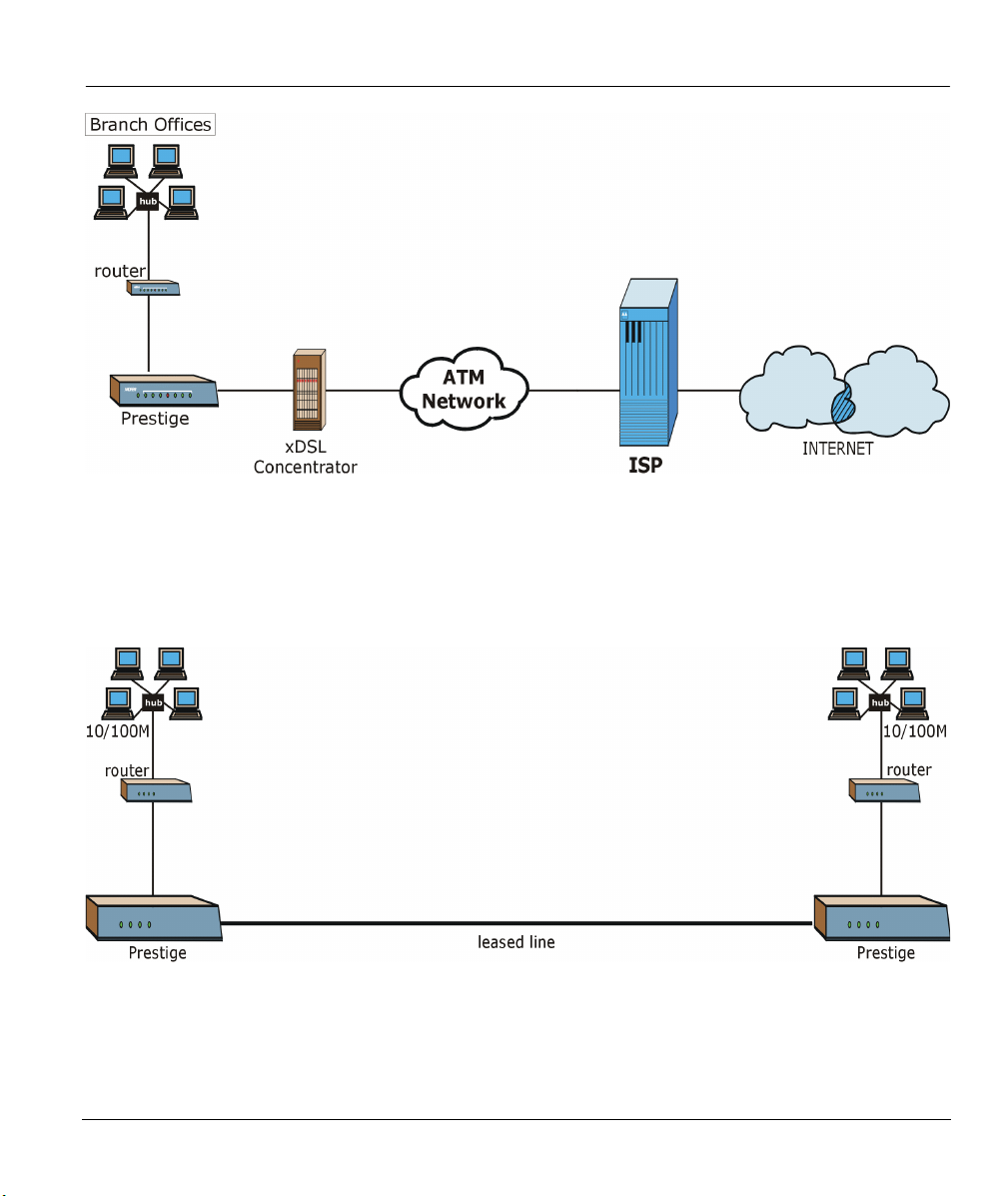
1.2.1 Internet Access Application
The following figure depicts a typical Internet access application using your Prestige.
1-2 Getting to Know Your G.SHDSL CSU/DSU
Prestige 724 G.SHDSL CSU/DSU
Figure 1-1 Internet Access Application
1.2.2 LAN-to-LAN Application
You can use the Prestige to connect two geographically dispersed networks over the DSL line. A typical
LAN-to-LAN application is shown next.
Figure 1-2 LAN-to-LAN Application
Getting to Know Your G.SHDSL CSU/DSU 1-3

Prestige 724 G.SHDSL CSU/DSU
Chapter 2
Hardware Installation and Initial Setup
This chapter shows how to make connections and set up your DSL connection using the SMT.
2.1 Installation Requirements
In addition to your Prestige package, your computer should have the following hardware and software:
• A console port (to establish a connection to the Prestige).
• Communications software configured as follows: VT100 terminal emulation; 9600 baud; no parity,
8 data bits, 1 stop bit, no flow control.
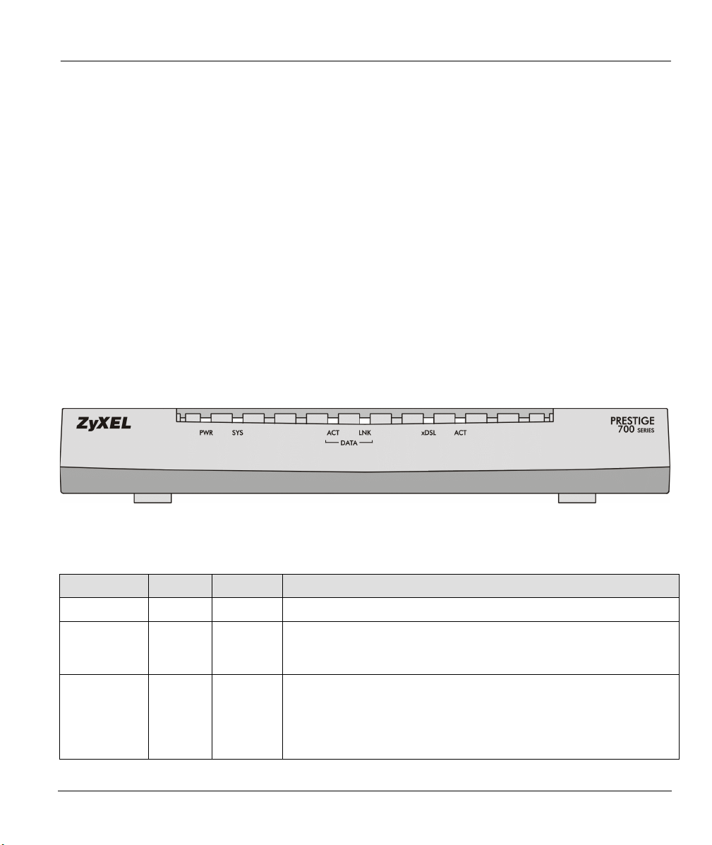
2.2 Front Panel LEDs of the Prestige 724
The LED indicators on the front panel show the operational status of the Prestige.
Figure 2-1 Front Panel of Prestige 724
Table 2-1 LED Functions
LED COLOR STATUS DESCRIPTION
PWR Green On The Prestige is receiving power.
SYS Green On
Blinking
Off
DATA
ACT Green Off
Blinking
LNK Green On The link is up.
Hardware Installation and Initial Setup 2-1
The Prestige is on and functioning properly.
The system is rebooting or running self-diagnostics.
The Prestige is not ready, has a malfunction or is off.
The data port is not transmitting or receiving data.
The data port is transmitting or receiving data.
Prestige 724 G.SHDSL CSU/DSU
LED COLOR STATUS DESCRIPTION
Off The link is down.
xDSL Green On
Blinking
Off
ACT Green Off
Blinking
The G.SHDSL link is connected.
The G.SHDSL link is connecting.
The G.SHDSL link is disconnected.
The data port is not transmitting or receiving data.
The data port is transmitting or receiving data.
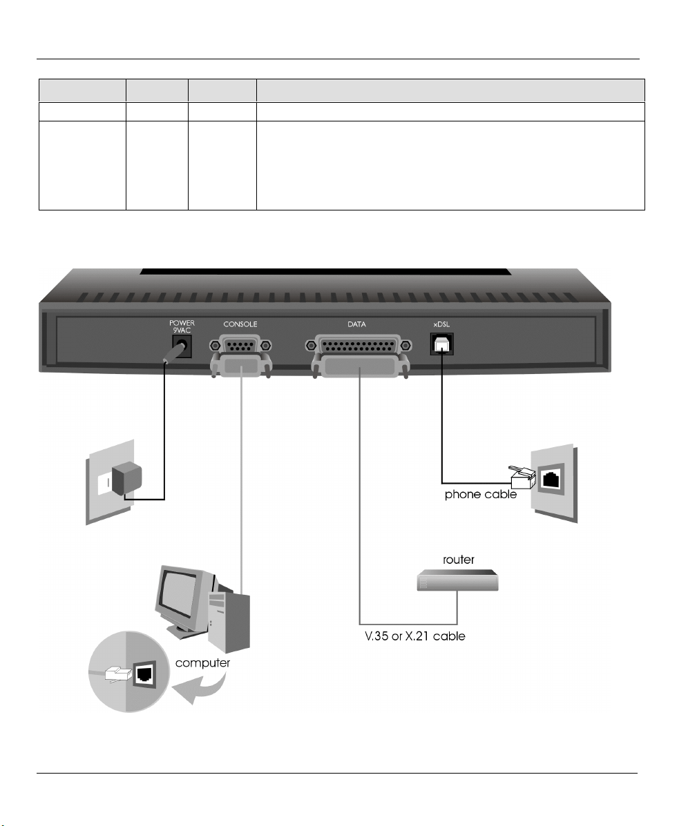
2.3 Rear Panel and Connections of the Prestige 724
Figure 2-2 Rear Panel Connections of the Prestige 724
2-2 Hardware Installation and Initial Setup

Prestige 724 G.SHDSL CSU/DSU
Step 1. Connecting the xDSL Line
Connect the Prestige (port labeled xDSL) into the telephone jack using the telephone cable (supplied).
Step 2. Connecting the DATA Port to your Router
Connect one end of the included data port cable (V.35 or X.21) to the DATA port of your Prestige and the
other end to your router.
Step 3. Connecting a Computer to the Prestige
For the initial configuration of your Prestige, you need to use terminal emulator software on your computer
and connect it to the Prestige through the CONSOLE port. Connect the 9-pin end of the console cable to
the console port of the Prestige and the other end (choice of 9-pin or 25-pin, depending on your computer)
end to a serial port (COM1, COM2 or other COM port) of your computer. You can use an extension RS232 cable if the enclosed one is too short. After the initial setup, you can modify the configuration remotely
through telnet connections.
Step 4. Connecting the Power Adapter to your Prestige
Connect the power adapter to the port labeled POWER on the rear panel of your Prestige.
To prevent damage to the Prestige, first make sure you have the correct power
adapter. See the Power Adapter Specification Appendix for regional
specifications.
2.4 Turning On Your Prestige
You can now turn on your Prestige by flipping the power switch to the on position (I is ON, O is OFF).
Step 1. Initial Screen
When you turn on your Prestige, it performs several internal tests as well as line initialization. After the
initialization, the Prestige prompts you to press [ENTER] to continue, as shown.
Copyright (c) 1994 - 2001 ZyXEL Communications Corp.
HWSAR (FPGA) : programming (11969) ... done
HWSAR (FPGA) : testing ... done
Wan Channel init ............ done
Press ENTER to continue...
Figure 2-3 Power-On Display
Hardware Installation and Initial Setup 2-3

Prestige 724 G.SHDSL CSU/DSU
Step 2. Entering the Default System Password
The login screen will prompt you to type the password. For your first login, type the default password 1234.
The screen displays an “X” for each character you type.
Enter Password : XXXX
Figure 2-4 Login Screen
If, after logging on, there is no activity for longer than five minutes, your Prestige
will automatically log you out and display a blank screen. Press [ENTER] to bring
up the login screen again.
2.5 Navigating the SMT Interface
Use the SMT (System Management Terminal) interface to configure your Prestige. The following figure is
an overview of the Prestige SMT menu screens.
2-4 Hardware Installation and Initial Setup

Prestige 724 G.SHDSL CSU/DSU
Figure 2-5 Prestige 724 SMT Menu Overview
Hardware Installation and Initial Setup 2-5
Prestige 724 G.SHDSL CSU/DSU
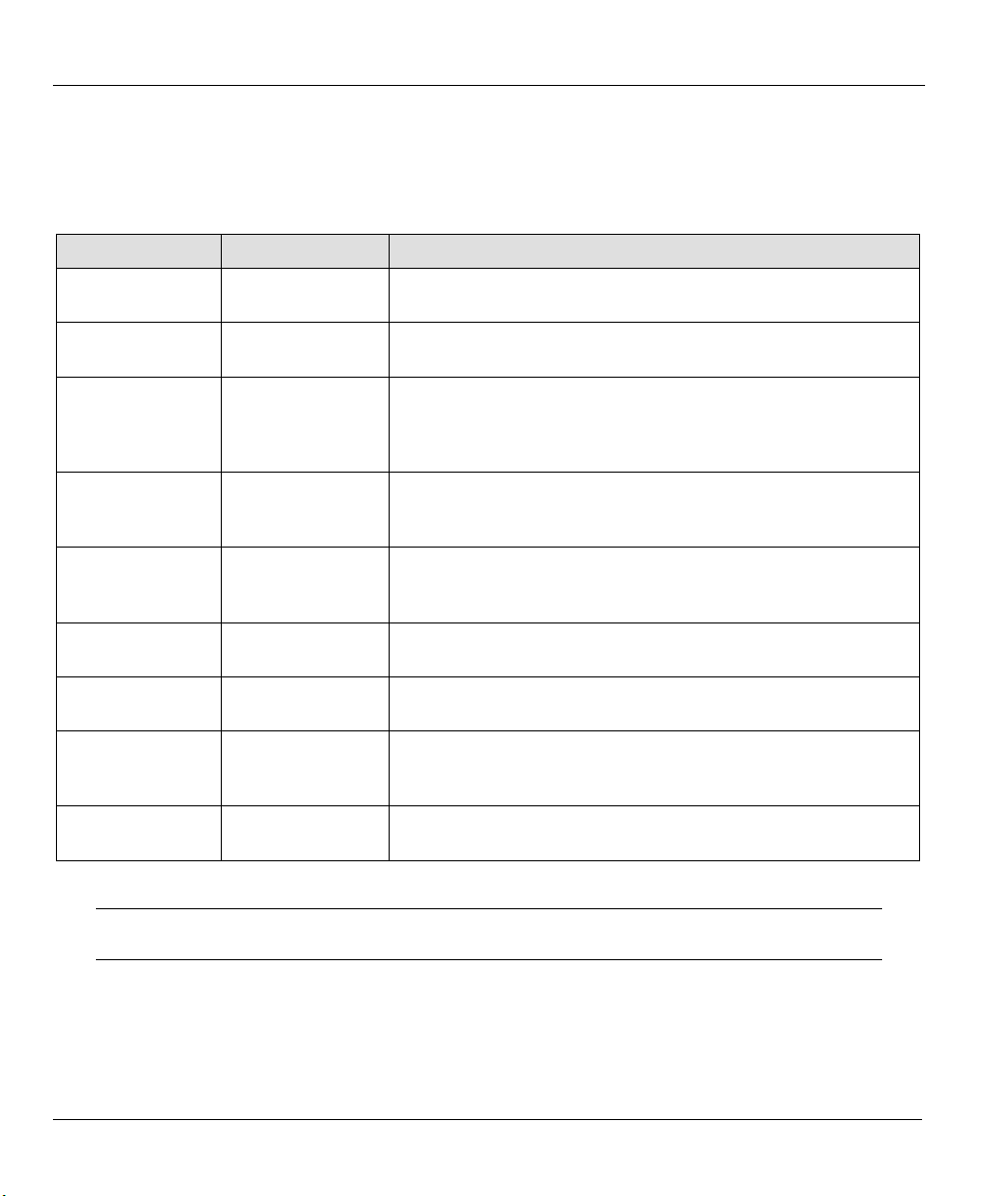
2.6 SMT Menu Commands
Before changing the configuration, familiarize yourself with the operations listed in the following table.
Table 2-2 Main Menu Commands
OPERATION KEYSTROKE DESCRIPTION
Move down to
another menu
Move up to a
previous menu
Move to a “hidden”
menu
Move the cursor [ENTER] or
Entering
information
Required fields
N/A fields <N/A> Some of the fields in the SMT will show a <N/A>. This symbol
Save your
configuration
Exit the SMT Type 99, then press
[ENTER] To move forward to a submenu, type in the number of the desired
submenu and press [ENTER].
[ESC] Press [ESC] to move back to the previous menu.
Press [SPACE
BAR] to change
Yes
to
then press
[ENTER].
[UP]/[DOWN] arrow
keys.
Type in or press
[SPACE BAR], then
press [ENTER].
?
>
<
[ENTER] Save your configuration by pressing [ENTER] at the message
[ENTER].
Fields beginning with “Edit” lead to hidden menus and have a
No
default setting of No. Press [SPACE BAR] once to change No to
Yes
, then press [ENTER] to go to the “hidden” menu.
Within a menu, press [ENTER] to move to the next field. You can
also use the [UP]/[DOWN] arrow keys to move to the previous
and the next field, respectively.
You need to fill in two types of fields. The first requires you to type
in the appropriate information. The second allows you to cycle
through the available choices by pressing [SPACE BAR].
All fields with the symbol <?> must be filled in order to be able to
save the new configuration.
refers to an option that is Not Applicable.
“Press ENTER to confirm or ESC to cancel”. Saving the data on
the screen will take you, in most cases to the previous menu.
Type 99 at the main menu prompt and press [ENTER] to exit the
SMT interface.
Remember to fill in all required fields (denoted by the symbol [?]).
N/A refers to an option that is Not Applicable.
After you type the password, the SMT displays the main menu, as shown as shown next.
2-6 Hardware Installation and Initial Setup
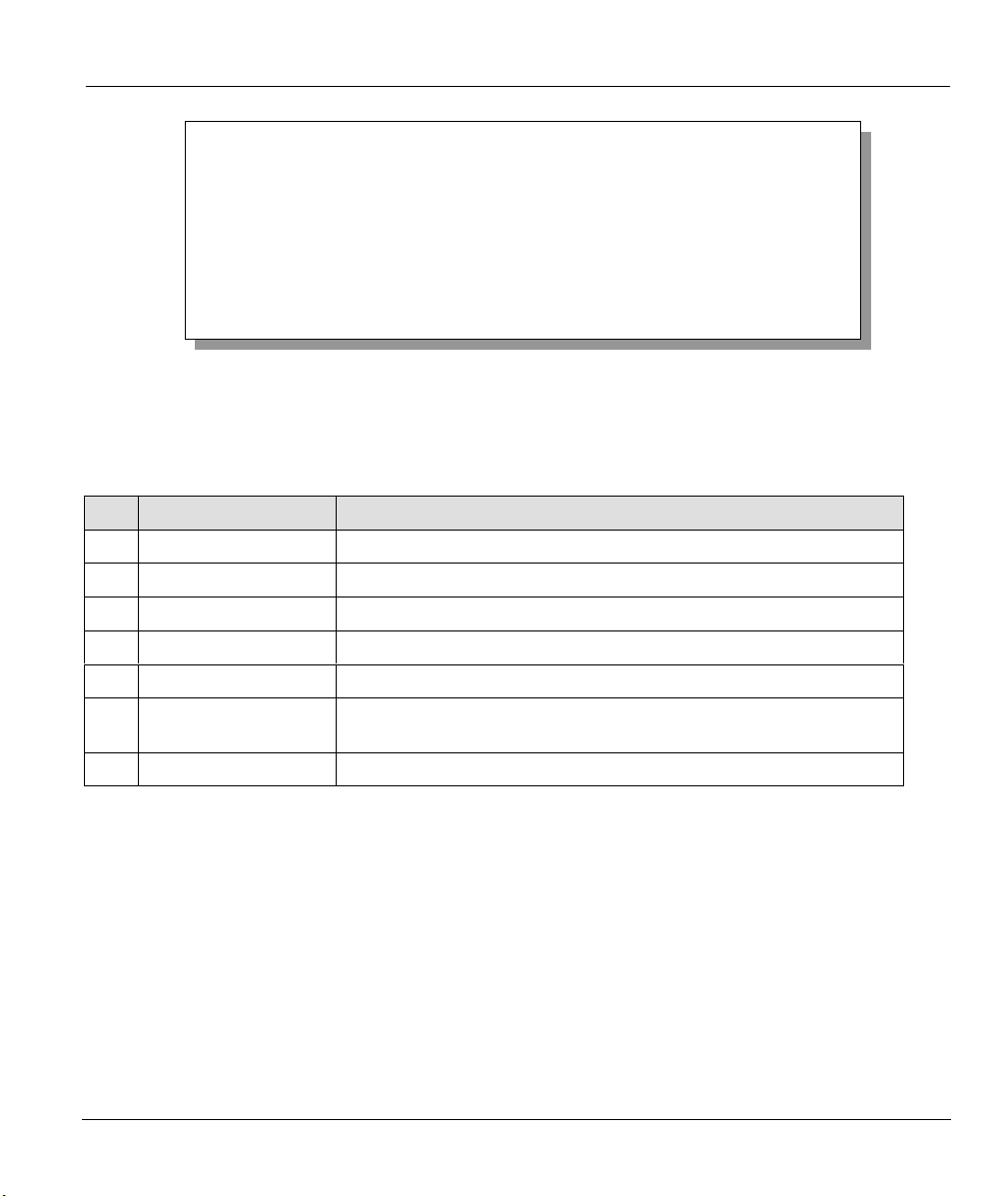
Prestige 724 G.SHDSL CSU/DSU
Copyright (c) 1994 - 2001 ZyXEL Communications Corp.
Getting Started
1. General Setup
2. WAN Setup
3. Data Port Setup
Advanced Applications
11. Channel Setup
Prestige 724 Main Menu
Advanced Management
23. System Password
24. System Maintenance
99. Exit
Enter Menu Selection Number:
Figure 2-6 SMT Main Menu
2.6.1 System Management Terminal Interface Summary
Table 2-3 Main Menu Summary
NO. MENU TITLE FUNCTION
1 General Setup Use this menu to set up routing/bridging and general information.
2 WAN Setup Use this menu to configure WAN settings.
3 Data Port Setup Use this menu to configure the data port interface.
11 Channel Setup Configure channel setup and remote management in this menu.
23 System Password Change your password in this menu (recommended).
24 System Maintenance From displaying system status to uploading firmware, this menu
provides comprehensive system maintenance.
99 Exit Use this menu to exit (necessary for remote configuration).
2.7 Changing the System Password
Change the default system password by performing the following steps.
Step 1. In the main menu, type 23 to display Menu 23 – System Password as shown in the following
figure. When the menu appears, type the old system password, i.e., 1234, and press [ENTER].
Hardware Installation and Initial Setup 2-7
 Loading...