


Prestige 650ME
ADSL Bridge
User's Guide
Version 3.40
September 2002

Prestige 650ME ADSL Bridge
Copyright
Copyright © 2002 by ZyXEL Communications Corporation.
The contents of this publication may not be reproduced in any part or as a whole, transcribed, stored in a
retrieval system, translated into any language, or transmitted in any form or by any means, electronic,
mechanical, magnetic, optical, chemical, photocopying, manual, or otherwise, without the prior written
permission of ZyXEL Communications Corporation.
Published by ZyXEL Communications Corporation. All rights reserved.
Disclaimer
ZyXEL does not assume any liability arising out of the application or use of any products, or software
described herein. Neither does it convey any license under its patent rights nor the patent rights of others.
ZyXEL further reserves the right to make changes in any products described herein without notice. This
publication is subject to change without notice.
Trademarks
ZyNOS (ZyXEL Network Operating System) is a registered trademark of ZyXEL Communications, Inc.
Other trademarks mentioned in this publication are used for identification purposes only and may be
properties of their respective owners.
ii Copyright

Prestige 650ME ADSL Bridge
Federal Communications Commission
(FCC) Interference Statement
This device complies with Part 15 of FCC rules. Operation is subject to the following two
conditions:
• This device may not cause harmful interference.
• This device must accept any interference received, including interference that may cause undesired
operations.
This equipment has been tested and found to comply with the limits for a Class B digital device pursuant to
Part 15 of the FCC Rules. These limits are designed to provide reasonable protection against harmful
interference in a commercial environment. This equipment generates, uses, and can radiate radio frequency
energy, and if not installed and used in accordance with the instructions, may cause harmful interference to
radio communications.
If this equipment does cause harmful interference to radio/television reception, which can be determined by
turning the equipment off and on, the user is encouraged to try to correct the interference by one or more of
the following measures:
1. Reorient or relocate the receiving antenna.
2. Increase the separation between the equipment and the receiver.
3. Connect the equipment into an outlet on a circuit different from that to which the receiver is connected.
4. Consult the dealer or an experienced radio/TV technician for help.
Notice 1
Changes or modifications not expressly approved by the party responsible for compliance could void the
user's authority to operate the equipment.
Certifications
Refer to the product page at www.zyxel.com
FCC Statement iii
.

Prestige 650ME ADSL Bridge
ZyXEL Limited Warranty
ZyXEL warrants to the original end user (purchaser) that this product is free from any defects in materials
or workmanship for a period of up to two years from the date of purchase. During the warranty period, and
upon proof of purchase, should the product have indications of failure due to faulty workmanship and/or
materials, ZyXEL will, at its discretion, repair or replace the defective products or components without
charge for either parts or labor, and to whatever extent it shall deem necessary to restore the product or
components to proper operating condition. Any replacement will consist of a new or re-manufactured
functionally equivalent product of equal value, and will be solely at the discretion of ZyXEL. This warranty
shall not apply if the product is modified, misused, tampered with, damaged by an act of God, or subjected
to abnormal working conditions.
Note
Repair or replacement, as provided under this warranty, is the exclusive remedy of the purchaser. This
warranty is in lieu of all other warranties, express or implied, including any implied warranty of
merchantability or fitness for a particular use or purpose. ZyXEL shall in no event be held liable for indirect
or consequential damages of any kind of character to the purchaser.
To obtain the services of this warranty, contact ZyXEL's Service Center for your Return Material
Authorization number (RMA). Products must be returned Postage Prepaid. It is recommended that the unit
be insured when shipped. Any returned products without proof of purchase or those with an out-dated
warranty will be repaired or replaced (at the discretion of ZyXEL) and the customer will be billed for parts
and labor. All repaired or replaced products will be shipped by ZyXEL to the corresponding return address,
Postage Paid. This warranty gives you specific legal rights, and you may also have other rights that vary
from country to country.
Safety Warnings
1. To reduce the risk of fire, use only No. 26 AWG or larger telephone wire.
2. Do not use this product near water, for example, in a wet basement or near a swimming pool.
3. Avoid using this product during an electrical storm. There may be a remote risk of electric shock from
lightening.
iv ZyXEL Warranty

Prestige 650ME ADSL Bridge
Customer Support
Please have the following information ready when you contact customer support.
• Product model and serial number.
• Information in Menu 24.2.1 – System Information.
• Warranty Information.
• Date that you received your device.
• Brief description of the problem and the steps you took to solve it.
METHOD
LOCATION
WORLDWIDE
AMERICA
E-MAIL
SUPPORT/SALES
support@zyxel.com.tw
sales@zyxel.com.tw
support@zyxel.com +1-714-632-0882
sales@zyxel.com
support@zyxel.dk +45-3955-0700 www.zyxel.dk SCANDINAVIA
sales@zyxel.dk
support@zyxel.de +49-2405-6909-0 www.zyxel.de GERMANY
sales@zyxel.de
+886-3-578-2439 ftp.europe.zyxel.com
+1-714-632-0858 ftp.zyxel.com
+45-3955-0707 ftp.zyxel.dk
+49-2405-6909-99
TELEPHONE/FAX WEB SITE/ FTP SITE REGULAR MAIL
+886-3-578-3942 www.zyxel.com
www.europe.zyxel.com
www.zyxel.com NORTH
800-255-4101
ZyXEL Communications Corp.,
6 Innovation Road II, ScienceBased Industrial Park, Hsinchu
300, Taiwan.
ZyXEL Communications Inc.,
1650 Miraloma Avenue,
Placentia, CA 92870, U.S.A.
ZyXEL Communications A/S,
Columbusvej 5, 2860 Soeborg,
Denmark.
ZyXEL Deutschland GmbH.
Adenauerstr. 20/A4 D-52146
Wuerselen, Germany
Customer Support v

Prestige 650ME ADSL Bridge
Table of Contents
Copyright .....................................................................................................................................................ii
Federal Communications Commission (FCC) Interference Statement .................................................iii
ZyXEL Limited Warranty......................................................................................................................... iv
Customer Support ....................................................................................................................................... v
List of Figures............................................................................................................................................. xi
List of Tables............................................................................................................................................. xiv
Preface....................................................................................................................................................... xvi
What is DSL?..........................................................................................................................................xviii
GETTING STARTED ..................................................................................................................................... I
Chapter 1 Getting To Know Your Prestige.............................................................................................1-1
1.1 Prestige 650ME ADSL Bridge ...................................................................................................1-1
1.2 Features of the Prestige...............................................................................................................1-1
1.3 Applications for the Prestige.......................................................................................................1-6
1.3.1 Internet Access....................................................................................................................1-6
1.3.2 LAN to LAN Application ...................................................................................................1-6
Chapter 2 Hardware Installation and Initial Setup...............................................................................2-1
2.1 Front Panel LEDs of the Prestige................................................................................................2-1
2.2 Rear Panel Connections of the Prestige ......................................................................................2-2
2.2.1 DSL Port .............................................................................................................................2-4
2.2.2 Console Port........................................................................................................................2-4
2.2.3 LAN 10/100M Port.............................................................................................................2-4
2.2.4 Power Port...........................................................................................................................2-4
2.2.5 Reset Button........................................................................................................................2-4
2.3 Additional Installation Requirements .........................................................................................2-4
2.4 Prestige with POTS..................................................................................................................... 2-5
2.4.1 Connecting a POTS Splitter................................................................................................2-5
2.4.2 Telephone Microfilters........................................................................................................2-6
2.5 Prestige With ISDN ....................................................................................................................2-6
2.6 Turning On Your Prestige...........................................................................................................2-7
2.7 Configuring Your Prestige For Internet Access..........................................................................2-7
2.7.1 Initial Screen .......................................................................................................................2-8
2.7.2 Entering Password ..............................................................................................................2-8
2.8 Resetting the Prestige..................................................................................................................2-8
2.8.1 Methods of Restoring Factory-Defaults..............................................................................2-9
2.8.2 Procedure To Use The Reset Button................................................................................... 2-9
2.8.3 Prestige SMT Menu Overview ...........................................................................................2-9
2.9 Navigating the SMT Interface...................................................................................................2-11
2.9.1 System Management Terminal Interface Summary..........................................................2-12
2.10 Changing the System Password ............................................................................................2-13
vi Table of Contents

Prestige 650ME ADSL Bridge
2.11 General Setup ....................................................................................................................... 2-13
2.11.1 Dynamic DNS.................................................................................................................. 2-14
2.11.2 Procedure To Configure Menu 1...................................................................................... 2-14
2.11.3 Procedure to Configure Dynamic DNS............................................................................ 2-15
2.12 LAN Setup ........................................................................................................................... 2-16
2.12.1 LAN Port Filter Setup ...................................................................................................... 2-17
2.13 Protocol Dependent Ethernet Setup ..................................................................................... 2-17
Chapter 3 Internet Access ....................................................................................................................... 3-1
3.1 Factory Ethernet Defaults........................................................................................................... 3-1
3.2 LANs and WANs ....................................................................................................................... 3-1
3.2.1 LANs, WANs and the Prestige........................................................................................... 3-1
3.3 TCP/IP Parameters ..................................................................................................................... 3-2
3.3.1 IP Address and Subnet Mask.............................................................................................. 3-2
3.3.2 Private IP Addresses........................................................................................................... 3-3
3.3.3 RIP Setup ........................................................................................................................... 3-3
3.3.4 DHCP Configuration.......................................................................................................... 3-4
3.4 IP Multicast ................................................................................................................................ 3-5
3.5 IP Policies .................................................................................................................................. 3-5
3.6 IP Alias....................................................................................................................................... 3-5
3.6.1 IP Alias Setup..................................................................................................................... 3-6
3.7 Route IP Setup............................................................................................................................ 3-8
3.8 TCP/IP Ethernet Setup and DHCP............................................................................................. 3-8
3.9 Multiplexing............................................................................................................................. 3-11
3.9.1 VC-based Multiplexing.................................................................................................... 3-11
3.9.2 LLC-based Multiplexing .................................................................................................. 3-11
3.10 Encapsulation ....................................................................................................................... 3-11
3.10.1 PPP over Ethernet ............................................................................................................ 3-11
3.10.2 RFC 1483 ......................................................................................................................... 3-11
3.11 IP Address Assignment ........................................................................................................ 3-12
3.11.1 Using PPPoE Encapsulation............................................................................................. 3-12
3.11.2 Using RFC 1483 Encapsulation ....................................................................................... 3-12
3.12 Internet Access Configuration.............................................................................................. 3-12
3.12.1 Traffic Shaping.................................................................................................................3-13
ADVANCED APPLICATIONS......................................................................................................................II
Chapter 4 Remote Node Configuration................................................................................................. 4-1
4.1 Remote Node Setup.................................................................................................................... 4-1
4.1.1 Remote Node Profile.......................................................................................................... 4-1
4.1.2 Encapsulation and Multiplexing Scenarios ........................................................................ 4-2
4.1.3 Outgoing Authentication Protocol...................................................................................... 4-5
4.2 Remote Node Setup.................................................................................................................... 4-6
4.3 Remote Node Filter .................................................................................................................... 4-7
Table of Contents vii

Prestige 650ME ADSL Bridge
4.4 Traffic Redirect...........................................................................................................................4-8
4.4.1 Metric..................................................................................................................................4-9
4.4.2 Traffic Redirect Setup.......................................................................................................4-10
Chapter 5 Remote Node TCP/IP Configuration ....................................................................................5-1
5.1 TCP/IP Configuration .................................................................................................................5-1
5.1.1 IP Static Route Setup ..........................................................................................................5-3
Chapter 6 Bridging Setup........................................................................................................................6-1
6.1 Bridging in General.....................................................................................................................6-1
6.2 Bridge Ethernet Setup.................................................................................................................6-1
6.2.1 Remote Node Bridging Setup .............................................................................................6-1
6.2.2 Bridge Static Route Setup...................................................................................................6-2
Chapter 7 Network Address Translation (NAT)....................................................................................7-1
7.1 Introduction.................................................................................................................................7-1
7.1.1 Applying NAT ....................................................................................................................7-2
7.1.2 Configuring a Server behind NAT...................................................................................... 7-4
7.2 General NAT Examples..............................................................................................................7-6
7.2.1 Example 1: Internet Access Only........................................................................................7-6
7.2.2 Example 2: Internet Access with an Inside Server..............................................................7-8
ADVANCED MANAGEMENT................................................................................................................... III
Chapter 8 Filter Configuration ...............................................................................................................8-1
8.1 About Filtering............................................................................................................................8-1
8.2 Configuring a Filter Set ..............................................................................................................8-4
8.2.1 Filter Rules Summary Menus .............................................................................................8-8
8.3 Configuring a Filter Rule ............................................................................................................8-9
8.3.1 TCP/IP Filter Rule ..............................................................................................................8-9
8.3.2 Generic Filter Rule............................................................................................................8-14
8.4 Filter Types and NAT ...............................................................................................................8-16
8.5 Example Filter...........................................................................................................................8-16
8.6 Applying Filters and Factory Defaults......................................................................................8-19
8.6.1 Ethernet Traffic.................................................................................................................8-20
8.6.2 Remote Node Filters .........................................................................................................8-20
Chapter 9 SNMP Configuration..............................................................................................................9-1
9.1 About SNMP...............................................................................................................................9-1
9.2 Supported MIBs..........................................................................................................................9-2
9.3 SNMP Configuration ..................................................................................................................9-2
9.4 SNMP Traps ...............................................................................................................................9-4
Chapter 10 System Information and Diagnosis ...................................................................................10-1
10.1 System Status ........................................................................................................................ 10-1
10.2 System Information and Console Port Speed........................................................................10-3
10.2.1 System Information...........................................................................................................10-3
10.2.2 Console Port Speed...........................................................................................................10-4
viii Table of Contents

Prestige 650ME ADSL Bridge
10.3 Log and Trace ...................................................................................................................... 10-5
10.3.1 Viewing Error Log ........................................................................................................... 10-5
10.3.2 UNIX Syslog.................................................................................................................... 10-6
10.4 Diagnostic ............................................................................................................................ 10-8
Chapter 11 Firmware and Configuration File Maintenance...............................................................11-1
11.1 Filename Conventions.......................................................................................................... 11-1
11.2 Backup Configuration .......................................................................................................... 11-2
11.2.1 Backup Configuration ...................................................................................................... 11-3
11.2.2 Using the FTP Command from the Command Line......................................................... 11-3
11.2.3 Example of FTP Commands from the Command Line.................................................... 11-3
11.2.4 GUI-based FTP Clients.................................................................................................... 11-4
11.2.5 TFTP and FTP over WAN Will Not Work When............................................................ 11-4
11.2.6 Backup Configuration Using TFTP ................................................................................. 11-5
11.2.7 TFTP Command Example................................................................................................ 11-5
11.2.8 GUI-based TFTP Clients.................................................................................................. 11-5
11.2.9 Backup Via Console Port ................................................................................................. 11-6
11.3 Restore Configuration .......................................................................................................... 11-7
11.3.1 Restore Using FTP ........................................................................................................... 11-8
11.3.2 Restore Using FTP Session Example............................................................................... 11-9
11.3.3 Restore Via Console Port ................................................................................................. 11-9
11.4 Uploading Firmware and Configuration Files.................................................................... 11-10
11.4.1 Firmware File Upload .................................................................................................... 11-10
11.4.2 Configuration File Upload ............................................................................................. 11-11
11.4.3 FTP File Upload Command from the DOS Prompt Example ........................................ 11-12
11.4.4 FTP Session Example of Firmware File Upload............................................................ 11-12
11.4.5 TFTP File Upload .......................................................................................................... 11-12
11.4.6 TFTP Upload Command Example ................................................................................. 11-13
11.4.7 Uploading Via Console Port........................................................................................... 11-13
11.4.8 Uploading Firmware File Via Console Port................................................................... 11-14
11.4.9 Example Xmodem Firmware Upload Using HyperTerminal......................................... 11-14
11.4.10 Uploading Configuration File Via Console Port ........................................................ 11-15
11.4.11 Example Xmodem Configuration Upload Using HyperTerminal .............................. 11-15
Chapter 12 System Maintenance and Information ............................................................................. 12-1
12.1 Command Interpreter Mode ................................................................................................. 12-1
12.2 Call Control Support ............................................................................................................12-2
12.2.1 Budget Management ........................................................................................................ 12-2
12.3 Time and Date Setting.......................................................................................................... 12-4
12.3.1 Resetting the Time ........................................................................................................... 12-5
Chapter 13 IP Policy Routing ............................................................................................................... 13-1
13.1 Introduction .......................................................................................................................... 13-1
13.2 Benefits ................................................................................................................................ 13-1
Table of Contents ix

Prestige 650ME ADSL Bridge
13.3 Routing Policy ......................................................................................................................13-1
13.4 IP Routing Policy Setup........................................................................................................13-2
13.5 Applying an IP Policy ...........................................................................................................13-5
13.5.1 Ethernet IP Policies...........................................................................................................13-5
13.6 IP Policy Routing Example...................................................................................................13-7
Chapter 14 Call Scheduling...................................................................................................................14-1
14.1 Introduction...........................................................................................................................14-1
Chapter 15 Remote Management ......................................................................................................... 15-1
15.1 Telnet ....................................................................................................................................15-1
15.2 FTP .......................................................................................................................................15-1
15.3 Web.......................................................................................................................................15-1
15.4 Remote Management ............................................................................................................15-1
15.4.1 Remote Management Setup .............................................................................................. 15-2
15.4.2 Remote Management Limitations.....................................................................................15-3
15.5 Remote Management and NAT ............................................................................................15-3
15.6 System Timeout .................................................................................................................... 15-3
ADDITIONAL INFORMATION .................................................................................................................IV
Chapter 16 Troubleshooting ..................................................................................................................16-1
16.1 Problems Starting Up the Prestige ........................................................................................16-1
16.2 Problems with the LAN Interface .........................................................................................16-1
16.3 Problems with the WAN Interface........................................................................................16-2
16.4 Problems with Internet Access..............................................................................................16-2
16.5 Problems with the Password .................................................................................................16-3
16.6 Problems with Telnet ............................................................................................................16-3
Appendix A Universal Plug and Play (UPnP) .......................................................................................... E
Appendix B PPPoE..................................................................................................................................... G
Appendix C Virtual Circuit Topology........................................................................................................ I
Appendix D Boot Module Commands...................................................................................................... K
Appendix E Power Adapter Specifications.............................................................................................. M
Appendix F TCP/IP .................................................................................................................................... O
Index ............................................................................................................................................................ U
x Table of Contents

Prestige 650ME ADSL Bridge
List of Figures
Figure 1-1 Internet Access Application.......................................................................................................... 1-6
Figure 1-2 LAN-to-LAN Application ............................................................................................................ 1-7
Figure 2-1 Prestige Front Panel...................................................................................................................... 2-1
Figure 2-2 Prestige Rear Panel and Connections ........................................................................................... 2-3
Figure 2-3 Connecting a POTS Splitter ......................................................................................................... 2-5
Figure 2-4 Connecting a Microfilter .............................................................................................................. 2-6
Figure 2-5 Prestige with ADSL over ISDN.................................................................................................... 2-7
Figure 2-6 Power-On Display........................................................................................................................ 2-8
Figure 2-7 Login Screen ................................................................................................................................ 2-8
Figure 2-8 Prestige SMT Menu Overview................................................................................................... 2-10
Figure 2-9 SMT Main Menu........................................................................................................................ 2-12
Figure 2-10 Menu 23 – System Password.................................................................................................... 2-13
Figure 2-11 Menu 1 – General Setup ........................................................................................................... 2-14
Figure 2-12 Configure Dynamic DNS ......................................................................................................... 2-16
Figure 2-13 Menu 3 – LAN Setup ............................................................................................................... 2-17
Figure 2-14 Menu 3.1 – General Ethernet Setup.......................................................................................... 2-17
Figure 3-1 LAN & WAN IPs ......................................................................................................................... 3-2
Figure 3-2 Physical Network ......................................................................................................................... 3-6
Figure 3-3 Partitioned Logical Networks....................................................................................................... 3-6
Figure 3-4 Menu 3.2 – TCP/IP and DHCP Ethernet Setup ...........................................................................3-6
Figure 3-5 Menu 3.2.1 – IP Alias Setup ......................................................................................................... 3-7
Figure 3-6 Menu 1 – General Setup............................................................................................................... 3-8
Figure 3-7 Menu 3.2 – TCP/IP and DHCP Ethernet Setup ............................................................................3-9
Figure 3-8 Example of Traffic Shaping........................................................................................................ 3-14
Figure 3-9 Internet Access Setup ................................................................................................................. 3-14
Figure 4-1 Menu 11 – Remote Node Setup.................................................................................................... 4-2
Figure 4-2 Menu 11.1 – Remote Node Profile ............................................................................................... 4-3
Figure 4-3 Remote Node Network Layer Options ......................................................................................... 4-6
Figure 4-4 Menu 11.5 – Remote Node Filter ................................................................................................. 4-8
Figure 4-5 Traffic Redirect Setup Example ................................................................................................... 4-9
Figure 4-6 Menu 11.1 – Remote Node Profile ............................................................................................. 4-10
Figure 4-7 Menu 11.7 – Traffic Redirect Setup.............................................................................................4-11
Figure 5-1 Sample IP Addresses for a TCP/IP LAN-to-LAN Connection..................................................... 5-1
Figure 5-2 Menu 11.3 - Remote Node Network Layer Options..................................................................... 5-2
Figure 5-3 Sample Static Routing Topology .................................................................................................. 5-4
Figure 5-4 Menu 12 – Static Route Setup...................................................................................................... 5-4
Figure 5-5 Menu 12.1 – IP Static Route Setup............................................................................................... 5-5
Figure 5-6 Edit IP Static Route ...................................................................................................................... 5-5
Figure 6-1 Menu 11.3 – Remote Node Bridging Options .............................................................................. 6-2
List of Figures xi

Prestige 650ME ADSL Bridge
Figure 6-2 Menu 12.3.1 – Edit Bridge Static Route .......................................................................................6-3
Figure 7-1 Menu 4 – Applying NAT for Internet Access................................................................................7-3
Figure 7-2 Menu 11.3 – Applying NAT to the Remote Node .........................................................................7-4
Figure 7-3 Menu 15 – NAT Server Setup .......................................................................................................7-5
Figure 7-4 Multiple Servers Behind NAT Example........................................................................................7-6
Figure 7-5 NAT Example 1.............................................................................................................................7-7
Figure 7-6 Menu 4 – Internet Access & NAT Example ..................................................................................7-7
Figure 7-7 NAT Example 2.............................................................................................................................7-8
Figure 7-8 Menu 15 – Specifying an Inside Server ........................................................................................7-8
Figure 8-1 Outgoing Packet Filtering Process ................................................................................................8-2
Figure 8-2 Filter Rule Process ........................................................................................................................8-3
Figure 8-3 Menu 21 – Filter Set Configuration ..............................................................................................8-4
Figure 8-4 NetBIOS_WAN Filter Rules Summary.........................................................................................8-5
Figure 8-5 NetBIOS_LAN Filter Rules Summary..........................................................................................8-5
Figure 8-6 Telnet_WAN Filter Rules Summary..............................................................................................8-6
Figure 8-7 PPPoE Filter Rules Summary .......................................................................................................8-6
Figure 8-8 FTP_WAN Filter Rules Summary.................................................................................................8-7
Figure 8-9 WebSet1 Filter Rules Summary ....................................................................................................8-7
Figure 8-10 WebSet2 Filter Rule Summary ....................................................................................................8-7
Figure 8-11 Menu 21.1.1 – TCP/IP Filter Rule.............................................................................................8-10
Figure 8-12 Executing an IP Filter................................................................................................................8-13
Figure 8-13 Menu 21.5.1 – Generic Filter Rule ............................................................................................8-14
Figure 8-14 Protocol and Device Filter Sets.................................................................................................8-16
Figure 8-15 Sample Telnet Filter ..................................................................................................................8-17
Figure 8-16 Sample Filter – Menu 21.3.1.....................................................................................................8-18
Figure 8-17 Sample Filter Rules Summary – Menu 21.1 .............................................................................8-19
Figure 8-18 Filtering Ethernet Traffic........................................................................................................... 8-20
Figure 8-19 Filtering Remote Node Traffic ..................................................................................................8-21
Figure 9-1 SNMP Management Model...........................................................................................................9-1
Figure 9-2 Menu 22 – SNMP Configuration ..................................................................................................9-3
Figure 10-1 Menu 24 – System Maintenance ...............................................................................................10-1
Figure 10-2 Menu 24.1 – System Maintenance – Status...............................................................................10-2
Figure 10-3 Menu 24.2 – System Information and Console Port Speed.......................................................10-3
Figure 10-4 Menu 24.2.1 – System Maintenance – Information .................................................................. 10-4
Figure 10-5 Menu 24.2.2 – System Maintenance – Change Console Port Speed.........................................10-5
Figure 10-6 Menu 24.3 – System Maintenance – Log and Trace .................................................................10-5
Figure 10-7 Sample Error and Information Messages..................................................................................10-6
Figure 10-8 Menu 24.3.2 – System Maintenance – UNIX Syslog ...............................................................10-6
Figure 10-9 Menu 24.4 – System Maintenance – Diagnostic.......................................................................10-8
Figure 11-1 Telnet in Menu 24.5...................................................................................................................11-3
Figure 11-2 FTP Session Example................................................................................................................11-4
xii List of Figures

Prestige 650ME ADSL Bridge
Figure 11-3 System Maintenance – Backup Configuration ..........................................................................11-6
Figure 11-4 System Maintenance – Starting Xmodem Download Screen ....................................................11-6
Figure 11-5 Backup Configuration Example ................................................................................................11-7
Figure 11-6 Successful Backup Confirmation Screen...................................................................................11-7
Figure 11-7 Telnet into Menu 24.6................................................................................................................11-8
Figure 11-8 Restore Using FTP Session Example ........................................................................................11-9
Figure 11-9 System Maintenance – Restore Configuration ..........................................................................11-9
Figure 11-10 System Maintenance – Starting Xmodem Download Screen ..................................................11-9
Figure 11-11 Restore Configuration Example.............................................................................................11-10
Figure 11-12 Successful Restoration Confirmation Screen ........................................................................11-10
Figure 11-13 Telnet Into Menu 24.7.1 – Upload System Firmware............................................................11-11
Figure 11-14 Telnet Into Menu 24.7.2 – System Maintenance ...................................................................11-11
Figure 11-15 FTP Session Example of Firmware File Upload ...................................................................11-12
Figure 11-16 Menu 24.7.1 as seen using the Console Port .........................................................................11-14
Figure 11-17 Example Xmodem Upload ....................................................................................................11-14
Figure 11-18 Menu 24.7.2 as seen using the Console Port .........................................................................11-15
Figure 11-19 Example Xmodem Upload ....................................................................................................11-16
Figure 12-1 Command Mode in Menu 24.................................................................................................... 12-1
Figure 12-2 Valid Commands ...................................................................................................................... 12-2
Figure 12-3 Call Control.............................................................................................................................. 12-2
Figure 12-4 Budget Management................................................................................................................. 12-3
Figure 12-5 Menu 24 – System Maintenance .............................................................................................. 12-4
Figure 12-6 Menu 24.10 System Maintenance – Time and Date Setting..................................................... 12-4
Figure 13-1 IP Routing Policy Setup ........................................................................................................... 13-2
Figure 13-2 Menu 25.1 – Sample IP Routing Policy Setup ......................................................................... 13-3
Figure 13-3 IP Routing Policy ..................................................................................................................... 13-4
Figure 13-4 Menu 3.2 – TCP/IP and DHCP Ethernet Setup ........................................................................ 13-6
Figure 13-5 Menu 11.3 – Remote Node Network Layer Options ................................................................ 13-6
Figure 13-6 Example of IP Policy Routing .................................................................................................. 13-7
Figure 13-7 IP Routing Policy Example ...................................................................................................... 13-8
Figure 13-8 IP Routing Policy .................................................................................................................... 13-9
Figure 13-9 Applying IP Policies................................................................................................................. 13-9
Figure 14-1 Menu 26 – Schedule Setup....................................................................................................... 14-1
Figure 14-2 Schedule Set Setup ................................................................................................................... 14-2
Figure 14-3 Applying Schedule Set(s) to a Remote Node (PPPoE)............................................................. 14-4
Figure 15-1 Telnet Configuration on a TCP/IP Network ............................................................................. 15-1
Figure 15-2 Menu 24.11 – Remote Management Control............................................................................ 15-2
List of Figures xiii

Prestige 650ME ADSL Bridge
List of Tables
Table 2-1 Front Panel LED Description ........................................................................................................ 2-1
Table 2-2 Main Menu Commands ................................................................................................................2-11
Table 2-3 Main Menu Summary .................................................................................................................. 2-12
Table 2-4 General Setup Menu Fields.......................................................................................................... 2-15
Table 2-5 Configure Dynamic DNS Menu Fields........................................................................................ 2-16
Table 3-1 IP Alias Setup Menu Fields............................................................................................................ 3-7
Table 3-2 DHCP Ethernet Setup Menu Fields ............................................................................................... 3-9
Table 3-3 TCP/IP Ethernet Setup Menu Fields............................................................................................ 3-10
Table 3-4 Internet Account Information....................................................................................................... 3-12
Table 3-5 Internet Access Setup Menu Fields.............................................................................................. 3-15
Table 4-1 Remote Node Profile Menu Fields ................................................................................................ 4-3
Table 4-2 Remote Node Network Layer Options .......................................................................................... 4-6
Table 4-3 Menu 11.1 – Remote Node Profile (Traffic Redirect Field) ........................................................ 4-10
Table 4-4 Traffic Redirect Setup...................................................................................................................4-11
Table 5-1 TCP/IP-Related Fields in Menu 11.1 – Remote Node Profile ....................................................... 5-2
Table 5-2 TCP/IP Remote Node Configuration ............................................................................................. 5-2
Table 5-3 Edit IP Static Route Menu Fields................................................................................................... 5-5
Table 6-1 Remote Node Bridge Options........................................................................................................ 6-2
Table 6-2 Edit Bridge Static Route Menu Fields ........................................................................................... 6-3
Table 7-1 Services and Port Numbers............................................................................................................ 7-1
Table 7-2 Applying NAT in Menus 4 & 11.3 ................................................................................................. 7-4
Table 8-1 Abbreviations Used in the Filter Rules Summary Menu ............................................................... 8-8
Table 8-2 Rule Abbreviations Used ............................................................................................................... 8-8
Table 8-3 TCP/IP Filter Rule Menu Fields .................................................................................................. 8-10
Table 8-4 Generic Filter Rule Menu Fields ................................................................................................. 8-15
Table 8-5 Filter Sets Table ........................................................................................................................... 8-20
Table 9-1 SNMP Configuration Menu Fields ................................................................................................ 9-3
Table 9-2 SNMP Traps................................................................................................................................... 9-4
Table 9-3 Ports and Permanent Virtual Circuits............................................................................................. 9-4
Table 10-1 System Maintenance – Status Menu Fields................................................................................ 10-2
Table 10-2 Fields in System Maintenance ................................................................................................... 10-4
Table 10-3 System Maintenance Menu – Syslog Parameters ...................................................................... 10-6
Table 10-4 System Maintenance Menu – Diagnostic................................................................................... 10-9
Table 11-1 Filename Conventions ................................................................................................................11-2
Table 11-2 General Commands for GUI-based FTP Clients.........................................................................11-4
Table 11-3 General Commands for GUI-based TFTP Clients ......................................................................11-6
Table 12-1 Budget Management.................................................................................................................. 12-3
Table 12-2 Time and Date Setting Fields..................................................................................................... 12-5
Table 13-1 IP Routing Policy Setup............................................................................................................. 13-3
xiv List of Tables

Prestige 650ME ADSL Bridge
Table 13-2 IP Routing Policy....................................................................................................................... 13-4
Table 14-1 Schedule Set Setup Fields .......................................................................................................... 14-2
Table 15-1 Menu 24.11 – Remote Management Control ............................................................................. 15-2
Table 16-1 Troubleshooting the Start-Up of Your Prestige .......................................................................... 16-1
Table 16-2 Troubleshooting the LAN Interface ...........................................................................................16-1
Table 16-3 Troubleshooting the WAN Interface ..........................................................................................16-2
Table 16-4 Troubleshooting Internet Access................................................................................................ 16-2
Table 16-5 Troubleshooting the Password ................................................................................................... 16-3
Table 16-6 Troubleshooting Telnet............................................................................................................... 16-3
List of Tables xv

Prestige 650ME ADSL Bridge
Preface
Congratulations on your purchase of the Prestige 650ME ADSL Bridge.
There are two Prestige 650ME models, one for ADSL over POTS (Plain Old Telephone System) and one
for ADSL over ISDN (Integrated Synchronous Digital System). Both models are discussed together in this
guide.
The Prestige 650ME ADSL Bridge can run maximum upstream transmission rates of up to 832Kbps and
maximum downstream transmission rates of 8Mbps. The actual rate depends on the copper category of your
telephone wire, distance from the central office and the type of ADSL service subscribed to. See the What
is DSL section for more background information on DSL and ADSL.
The Prestige's 10/100M auto-negotiating LAN interface enables fast data transfer of either 10Mbps or
100Mbps in either half-duplex or full-duplex mode depending on your Ethernet network.
Your Prestige is easy to install and configure. All functions of the Prestige are software configurable via the
SMT (System Management Terminal) and web configurator. Advanced users may configure the Prestige
using CLI (Command Line Interface) commands.
Don’t forget to register your Prestige (fast, easy online registration at
www.zyxel.com) for free future product updates and information.
About This User's Guide
This user's guide covers all aspects of Prestige operations and shows you how to get the best out of the
multiple advanced features of your ADSL Bridge using the SMT. It is designed to guide you through the
correct configuration of your Prestige for various applications.
Related Documentation
Supporting Disk
More detailed information and examples can be found in our included disk (as well as on the
zyxel.com web site). This disk contains information on configuring your Prestige for Internet
Access, general and advanced FAQs, Application Notes, Troubleshooting, a reference for CI
Commands and bundled software.
Read Me First
Our Read Me First is designed to help you get up and running right away. It contains a detailed
easy-to-follow connection diagram, default settings, handy checklists and information on setting
up your network and configuring for Internet access.
ZyXEL Web Site
The ZyXEL download library at www.zyxel.com
glossary.
xvi Preface
contains additional support documentation and a

Prestige 650ME ADSL Bridge
Syntax Conventions
• “Type” means for you to type one or more characters and press the carriage return. “Select” or
“Choose” means for you to select one predefined choices.
• The SMT menu titles and labels are in Bold Times New Roman font. Predefined field choices are in
Bold Arial font. Command and arrow keys are enclosed in square brackets. [ENTER] means the
Enter, or carriage return key; [ESC] means the Escape key and [SPACE BAR] means the Space Bar.
• For brevity’s sake, we will use “e.g.,” as a shorthand for “for instance”, and “i.e.,” for “that is” or “in
other words” throughout this manual.
• The Prestige 650ME ADSL Bridge may be referred to as the P650 or the Prestige in this user’s guide.
The following section offers some background information on DSL. Skip to
Chapter 1 if you wish to begin working with your Prestige right away.
Preface xvii

Prestige 650ME ADSL Bridge
What is DSL?
DSL (Digital Subscriber Line) technology enhances the data capacity of the existing twisted-pair wire that
runs between the local telephone company switching offices and most homes and offices. While the wire
itself can handle higher frequencies, the telephone switching equipment is designed to cut off signals above
4,000 Hz to filter noise off the voice line, but now everybody is searching for ways to get more bandwidth
to improve access to the Web - hence DSL technologies.
There are actually seven types of DSL service, ranging in speeds from 16 Kbits/sec to 52 Mbits/sec. The
services are either symmetrical (traffic flows at the same speed in both directions), or asymmetrical (the
downstream capacity is higher than the upstream capacity). Asymmetrical services (ADSL) are suitable for
Internet users because more information is usually downloaded than uploaded. For example, a simple
button click in a web browser can start an extended download that includes graphics and text.
As data rates increase, the carrying distance decreases. That means that users who are beyond a certain
distance from the telephone company’s central office may not be able to obtain the higher speeds.
A DSL connection is a point-to-point dedicated circuit, meaning that the link is always up and there is no
dialing required.
What is ADSL?
It is an asymmetrical technology, meaning that the downstream data rate is much higher than the upstream
data rate. As mentioned, this works well for a typical Internet session in which more information is
downloaded, for example, from Web servers, than is uploaded. ADSL operates in a frequency range that is
above the frequency range of voice services, so the two systems can operate over the same cable.
xviii What is DSL?

Getting Started
PPaarrtt II::
GETTING STARTED
This part is structured as a step-by-step guide to help you connect, install and set up your
Prestige to operate on your network and to access the Internet. Described are Key Features and
Applications, Hardware Installation, Initial Setup and Internet Access.
I


Prestige 650ME ADSL Bridge
Chapter 1
Getting To Know Your Prestige
This chapter describes the key features and applications of your Prestige.
1.1 Prestige 650ME ADSL Bridge
Your Prestige integrates a high-speed 10/100Mbps auto-negotiating LAN interface and one high-speed
ADSL port into a single package. The Prestige is ideal for high-speed Internet browsing and making LAN-
to-LAN connections to remote networks.
1.2 Features of the Prestige
Your Prestige is packed with a number of features that give it the flexibility to provide a complete
networking solution for almost any user.
High Speed Internet Access
Your Prestige can support downstream transmission rates of up to 8Mbps and upstream transmission rates
of 832 Kbps. Prestige with ADSL over POTS also supports rate management.
10/100M Auto-negotiation Ethernet/Fast Ethernet Interface
This auto-negotiation feature allows the Prestige to detect the speed of incoming transmissions and adjust
appropriately without manual intervention. It allows data transfer of either 10 Mbps or 100 Mbps in either
half-duplex or full-duplex mode depending on your Ethernet network.
PPPoE Support (RFC2516)
PPPoE (Point-to-Point Protocol over Ethernet) emulates a dial-up connection. It allows your ISP to use their
existing network configuration with newer broadband technologies such as ADSL. The PPPoE driver on the
Getting To Know Your Prestige 1-1

Prestige 650ME ADSL Bridge
Prestige is transparent to the computers on the LAN, which see only Ethernet and are not aware of PPPoE
thus saving you from having to manage PPPoE clients on individual computers.
NAT for Single-IP-address Internet Access
The Prestige's SUA (Single User Account) feature allows multiple-user Internet access for the cost of a
single IP account. NAT supports popular Internet applications such as MS traceroute, CuSeeMe, IRC,
RealPlayer, VDOLive, Quake, and PPTP. No configuration is needed to support these applications.
Traffic Redirect
Traffic Redirect forwards WAN traffic to a backup gateway on the LAN when the Prestige cannot connect
to the Internet, thus acting as an auxiliary backup when your regular WAN connection fails.
• Universal Plug and Play (UPnP)
Using the standard TCP/IP protocol, the Prestige and other UPnP enabled devices can dynamically join a
network, obtain an IP address and convey its capabilities to other devices on the network.
Dynamic DNS Support
With Dynamic DNS support, you can have a static hostname alias for a dynamic IP address, allowing the
host to be more easily accessible from various locations on the Internet. You must register for this service
with a Dynamic DNS client.
Multiple PVC (Permanent Virtual Circuits) Support
Your Prestige supports up to 8 PVC’s.
ADSL Transmission Rate Standards
♦ Full-Rate (ANSI T1.413, Issue 2; G.dmt (G.992.1) with line rate support of up to 8 Mbps
downstream and 832 Kbps upstream.
♦ G.lite (G.992.2) with line rate support of up to 1.5Mbps downstream and 512Kbps upstream.
♦ Supports Multi-Mode standard (ANSI T1.413, Issue 2; G.dmt (G.992.1); G.994.1 and G.996.1 (for
ISDN only); G.991.1; G.lite (G992.2)).
♦ TCP/IP (Transmission Control Protocol/Internet Protocol) network layer protocol.
1-2 Getting To Know Your Prestige

Prestige 650ME ADSL Bridge
♦ ATM Forum UNI 3.1/4.0 PVC.
♦ Supports up to 8 PVCs (UBR, CBR).
♦ Multiple Protocols over AAL5 (RFC 1483).
♦ PPP over Ethernet over AAL5 (RFC 2516).
♦ PPP over PAP (RFC 1334).
♦ PPP over CHAP (RFC 1994).
• Protocol Support
♦ DHCP Support
DHCP (Dynamic Host Configuration Protocol) allows the individual clients (computers) to obtain
the TCP/IP configuration at start-up from a centralized DHCP server. The Prestige has built-in
DHCP server capability enabled by default. It can assign IP addresses, an IP default gateway and
DNS servers to DHCP clients. The Prestige can now also act as a surrogate DHCP server (DHCP
Relay) where it relays IP address assignment from the actual real DHCP server to the clients.
♦ IP Alias
IP Alias allows you to partition a physical network into logical networks over the same Ethernet
interface. The Prestige supports three logical LAN interfaces via its single physical Ethernet
interface with the Prestige itself as the gateway for each LAN network.
♦ IP Policy Routing (IPPR)
Traditionally, routing is based on the destination address only and the router takes the shortest path
to forward a packet. IP Policy Routing (IPPR) provides a mechanism to override the default
routing behavior and alter the packet forwarding based on the policy defined by the network
administrator.
♦ PPP (Point-to-Point Protocol) link layer protocol.
♦ Transparent bridging (IEEE 802.1D) with bridge filters for unsupported network layer protocols.
♦ RIP I/RIP II
Getting To Know Your Prestige 1-3

Prestige 650ME ADSL Bridge
♦ IGMP Proxy
♦ ICMP support
♦ MIB II support (RFC 1213)
Networking Compatibility
Your Prestige is compatible with the major ADSL DSLAM (Digital Subscriber Line Access Multiplexer)
providers, making configuration as simple as possible for you.
Multiplexing
The Prestige supports VC-based and LLC-based multiplexing.
Encapsulation
The Prestige supports RFC 1483 as well as PPP over Ethernet (RFC 2516) encapsulations.
Network Management
♦ Menu driven SMT (System Management Terminal) management
♦ Embedded web configurator
♦ CLI (Command Line Interpreter)
♦ Remote SMT session via Telnet
♦ SNMP manageable
♦ Local SMT session via console port
♦ DHCP Server/Client
♦ Built-in Diagnostic Tools
♦ Syslog
♦ Telnet Support (Password-protected telnet access to internal configuration manager)
♦ TFTP/FTP server, firmware upgrade and configuration backup/support supported
♦ Supports OAM F4/F5 loop-back, AIS and RDI OAM cells
1-4 Getting To Know Your Prestige

Prestige 650ME ADSL Bridge
• Remote Management
• Other PPPoE Features
♦ PPPoE idle time out
♦ PPPoE Dial on Demand
• Diagnostics Capabilities
The Prestige can perform self-diagnostic tests. These tests check the integrity of the following circuitry:
♦ FLASH memory
♦ ADSL circuitry
♦ RAM
♦ LAN port
Filters
The Prestige's packet filtering functions allow added network security and management.
Ease of Installation
Your Prestige is designed for quick, intuitive and easy installation.
Housing
Your Prestige's all new compact and ventilated housing minimizes space requirements making it easy to
position anywhere in your busy office.
Getting To Know Your Prestige 1-5
Prestige 650ME ADSL Bridge
1.3 Applications for the Prestige
1.3.1 Internet Access
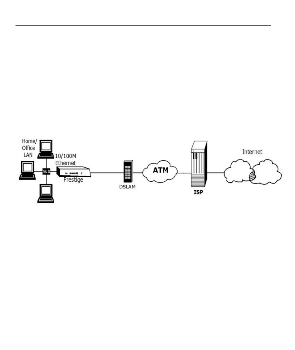
The Prestige is the ideal high-speed Internet access solution. Your Prestige supports the TCP/IP protocol,
which the Internet uses exclusively. It is compatible with all major ADSL DSLAM (Digital Subscriber Line
Access Multiplexer) providers. A DSLAM is a rack of ADSL line cards with data multiplexed into a
backbone network interface/connection (for example, T1, OC3, DS3, ATM or Frame Relay). Think of it as
the equivalent of a modem rack for ADSL. A typical Internet Access application is shown below.
Figure 1-1 Internet Access Application
Internet Single User Account
For a SOHO (Small Office/Home Office) environment, your Prestige offers the Single User Account (SUA)
feature that allows multiple users on the LAN (Local Area Network) to access the Internet concurrently for
the cost of a single IP address.
1.3.2 LAN to LAN Application
You can use the Prestige to connect two geographically dispersed networks over the ADSL line. A typical
LAN-to-LAN application for your Prestige is shown as follows.
1-6 Getting To Know Your Prestige
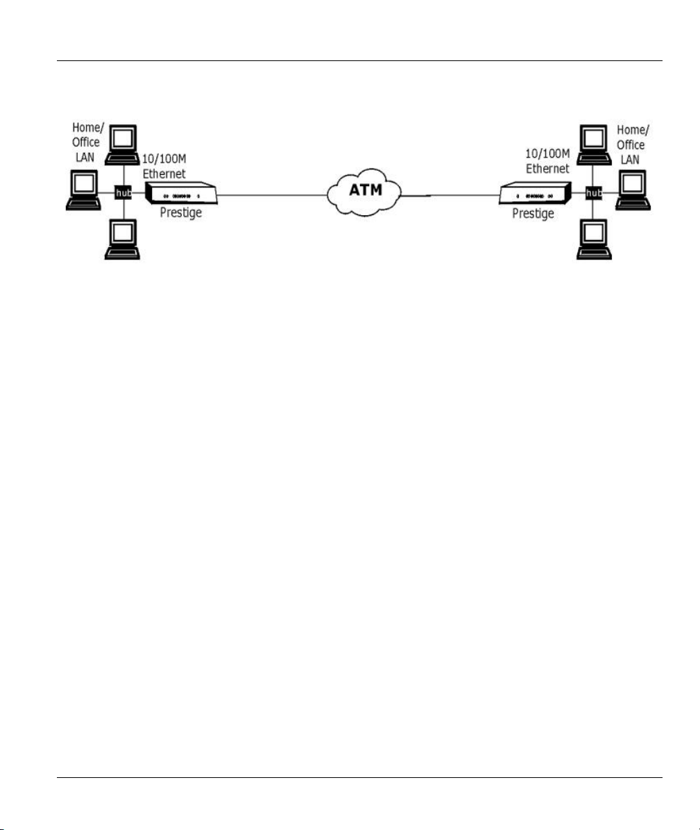
Prestige 650ME ADSL Bridge
Figure 1-2 LAN-to-LAN Application
Getting To Know Your Prestige 1-7

Prestige 650ME ADSL Bridge
Chapter 2
Hardware Installation and Initial Setup
This chapter describes the physical features of the Prestige and how to make cable connections.
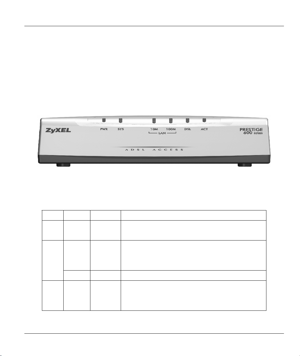
2.1 Front Panel LEDs of the Prestige
The LEDs on the front panel indicate the operational status of your Prestige
Figure 2-1 Prestige Front Panel
Table 2-1 Front Panel LED Description
LED COLOR STATUS DESCRIPTION
On The Prestige is receiving power. PWR Green
Off The Prestige is not receiving power.
SYS
LAN
10M
Hardware Installation and Initial Setup 2-1
Green
Orange On Power gasp action. Power to the Prestige is too low.
Green
On The Prestige is functioning properly.
Blinking The Prestige is rebooting.
Off The system is not ready or has malfunctioned.
On The Prestige has a successful 10Mb Ethernet connection.
Blinking The Prestige is sending/receiving data.
Off The Prestige does not have 10Mb Ethernet connection.

Prestige 650ME ADSL Bridge
Table 2-1 Front Panel LED Description
LED COLOR STATUS DESCRIPTION
LAN
100M
DSL Green
Orange
On The Prestige has a successful 100Mb Ethernet
connection.
Blinking The Prestige is sending/receiving data.
Off The Prestige does not have 100Mb Ethernet connection.
On The Prestige is linked successfully to a DSLAM.
Blinking The Prestige is initializing the DSL line.
Off The DSL link is down.
Blinking The Prestige is sending/receiving data. ACT Green
Off The system is ready, but is not sending/receiving data.
2.2 Rear Panel Connections of the Prestige
The following figure shows the rear panel and connections of your Prestige.
2-2 Hardware Installation and Initial Setup

Prestige 650ME ADSL Bridge
Figure 2-2 Prestige Rear Panel and Connections
Hardware Installation and Initial Setup 2-3

Prestige 650ME ADSL Bridge
2.2.1 DSL Port
Connect the Prestige directly to the wall jack using the included DSL cable. Connect a microfilter(s)
between the wall jack and your telephone(s). A microfilter acts as a low-pass filter (voice transmission
takes place in the 0 to 4KHz bandwidth) and is an optional purchase.
2.2.2 Console Port
Use terminal emulator software on a computer for configuring your Prestige via console port. Connect the
7-pin end of a console cable to the console port of the Prestige and the 9-pin female end to a serial port
(COM1, COM2 or other COM port) of your computer.
2.2.3 LAN 10/100M Port
Ethernet 10Base-T/100Base-T networks use Shielded Twisted Pair (STP) cable with RJ-11 connectors
(POTS) that look like a bigger telephone plug with 8 pins. Use the crossover cable to connect your Prestige
to a computer directly or use a straight-through Ethernet cable to connect to an external hub, then connect
one end of the straight-through cable from the hub to the NIC on the computer.
When the Prestige is on and properly connected to a computer or a hub, the LAN
LED on the front panel turns on.
2.2.4 Power Port
Connect the power adapter to the port labeled POWER on the rear panel of your Prestige.
To avoid damage to the Prestige, make sure you use the correct power adapter.
Refer to the Power Adapter Specification Appendix for this information.
2.2.5 Reset Button
Refer to section 2.8 for information on the RESET button.
2.3 Additional Installation Requirements
A computer with an Ethernet 10Base-T/100Base-T NIC (Network Interface Card).
A computer equipped with communications software (for example, Hyper Terminal in Windows 95)
configured to the following parameters:
VT100 terminal emulation.
9600 baud rate.
2-4 Hardware Installation and Initial Setup

Prestige 650ME ADSL Bridge
Parity set to none, 8 data bits, 1 stop bit.
Flow control set to none.
After the Prestige has been successfully connected to your network, you can make future changes to the
configuration via Telnet or the embedded web configurator.
2.4 Prestige with POTS
Sections 2.4.1 and 2.4.2 relate to people who use their Prestige with ADSL over POTS (analog telephone
service) only.
2.4.1 Connecting a POTS Splitter
This is for the Prestige that follows the Full Rate (G.dmt) standard only. One major difference between
ADSL and dial-up modems is the optional telephone splitter. This device keeps the telephone and ADSL
signals separated, giving them the capability to provide simultaneous Internet access and telephone service
on the same line. Splitters also eliminate the destructive interference conditions caused by telephone sets.
The purchase of a POTS splitter is optional.
Noise generated from a telephone in the same frequency range, as the ADSL signal can be disruptive to the
ADSL signal. In addition, the impedance of a telephone when off-hook may be so low that it shunts the
strength of the ADSL signal. When a POTS splitter is installed at the entry point, where the line comes into
the home, it will filter the telephone signals before combining the ADSL and telephone signals transmitted
and received. The issues of noise and impedance are eliminated with a single POTS splitter installation.
A telephone splitter is easy to install as shown in the following figure.
Figure 2-3 Connecting a POTS Splitter
Step 1. Connect the side labeled “Phone” to your telephone.
Hardware Installation and Initial Setup 2-5

Prestige 650ME ADSL Bridge
Step 2. Connect the side labeled “Modem” to your Prestige.
Step 3. Connect the side labeled “Line” to the telephone wall jack.
2.4.2 Telephone Microfilters
Telephone voice transmissions take place in the lower frequency range, 0 - 4KHz, while ADSL
transmissions take place in the higher bandwidth range, above 4KHz. A microfilter acts as a low-pass filter,
for your telephone, to ensure that ADSL transmissions do not interfere with your telephone voice
transmissions. The purchase of a telephone microfilter is optional.
Step 1. Connect a phone cable from the wall jack to the single jack end of the Y- Connector.
Step 2. Connect a cable from the double jack end of the Y-Connector to the “wall side” of the
microfilter.
Step 3. Connect another cable from the double jack end of the Y-Connector to the Prestige.
Step 4. Connect the “phone side” of the microfilter to your telephone as shown in the following figure.
Figure 2-4 Connecting a Microfilter
2.5 Prestige With ISDN
This section relates to people who use their Prestige with ADSL over ISDN (digital telephone service) only.
The following is an example installation for the Prestige with ISDN.
2-6 Hardware Installation and Initial Setup

Prestige 650ME ADSL Bridge
Figure 2-5 Prestige with ADSL over ISDN
2.6 Turning On Your Prestige
At this point, you should have connected the DSL, LAN 10/100M, console and power ports to the
appropriate devices. Make sure the power adapter is plugged into an appropriate power source and the
power switch (located on the back of your Prestige) is “on” (or pressed).
2.7 Configuring Your Prestige For Internet Access
Configure your Prestige for Internet access using:
Web configurator (refer to the Read Me First)
SMT (System Management Terminal). Access the SMT via:
o LAN or WAN using Telnet
o Console port using terminal emulation software
The remainder of this user’s guide shows you how to configure the Prestige for Internet access using SMT
screens through the console port. There are also some sections in this guide that also focus on using Telnet
to configure the Prestige.
Hardware Installation and Initial Setup 2-7

Prestige 650ME ADSL Bridge
2.7.1 Initial Screen
When you turn on your Prestige, it performs several internal tests as well as line initialization. After the
initialization, the Prestige asks you to press [ENTER] to continue.
Copyright (c) 1994 - 2002 ZyXEL Communications Corp.
initialize ch = 0, ethernet address: 00:a0:c5:01:23:45
Wan Channel init ........ done
Loading ADSL modem F/W
................................................................. done
Press ENTER to continue...
Figure 2-6 Power-On Display
2.7.2 Entering Password
The login screen appears after you press [ENTER], prompting you to enter the password, as shown next.
For your first login, enter the default password “1234”. As you type the password, the screen displays an
“X” for each character you type.
Please note that if there is no activity for longer than five minutes after you log in, your Prestige will
automatically log you out and will display a blank screen. If you see a blank screen, press [ENTER] to
display the login screen again.
Enter Password : XXXX
Figure 2-7 Login Screen
2.8 Resetting the Prestige
If you forget your password or cannot access the Prestige, you will need to reload the factory-default
configuration file. Uploading the configuration file replaces the current configuration file with the factorydefault configuration file. This means that you will lose all configurations that you had previously and the
speed of the console port will be reset to the default of 9600bps with 8 data bit, no parity, one stop bit and
flow control set to none. The password will be reset to “1234” and the LAN IP address to 192.168.1.1 also.
Refer to the chapter on Firmware Maintenance for detailed, step-by-step instructions.
2-8 Hardware Installation and Initial Setup

Prestige 650ME ADSL Bridge
2.8.1 Methods of Restoring Factory-Defaults
You can erase the current configuration and restore factory defaults in three ways:
a. Use the web configurator (see the web configurator HTML help).
b. Upload the default configuration file via the console port. See later in this User’s Guide
for more information on how to transfer the configuration file to your Prestige using the
SMT menus.
c. Use the RESET button on the rear panel of the Prestige (see the next section).
2.8.2 Procedure To Use The Reset Button
Step 1. Turn your Prestige off and then on. Make sure the SYS LED is on (not blinking).
Step 2. Press the RESET button for five seconds and then release it. If the SYS LED begins to blink,
the defaults have been restored and the Prestige restarts.
2.8.3 Prestige SMT Menu Overview
The following figure gives you an overview of the various SMT menu screens of your Prestige.
Hardware Installation and Initial Setup 2-9

Prestige 650ME ADSL Bridge
Figure 2-8 Prestige SMT Menu Overview
2-10 Hardware Installation and Initial Setup

Prestige 650ME ADSL Bridge
2.9 Navigating the SMT Interface
The SMT (System Management Terminal) is the interface that you use to configure your Prestige.
Several operations that you should be familiar with before you attempt to modify the configuration are
listed in the table below.
Table 2-2 Main Menu Commands
OPERATION KEYSTROKE DESCRIPTION
Move down to
another menu
Move up to a
previous menu
Move to a “hidden”
menu
Move the cursor [ENTER] or
Entering
information
Required fields
N/A fields <N/A> Some of the fields in the SMT will show a <N/A>. This symbol
Save your
configuration
Exit the SMT Type 99, then press
[ENTER] To move forward to a submenu, type in the number of the desired
submenu and press [ENTER].
[ESC] Press [ESC] to move back to the previous menu.
Press [SPACE
BAR] to change No
to Yes then press
[ENTER].
[UP]/[DOWN] arrow
keys.
Type in or press
[SPACE BAR], then
press [ENTER].
<?>
[ENTER] Save your configuration by pressing [ENTER] at the message
[ENTER].
Fields beginning with “Edit” lead to hidden menus and have a
default setting of No. Press [SPACE BAR] once to change No to
Yes, then press [ENTER] to go to the “hidden” menu.
Within a menu, press [ENTER] to move to the next field. You can
also use the [UP]/[DOWN] arrow keys to move to the previous
and the next field, respectively.
You need to fill in two types of fields. The first requires you to type
in the appropriate information. The second allows you to cycle
through the available choices by pressing [SPACE BAR].
All fields with the symbol <?> must be filled in order to be able to
save the new configuration.
refers to an option that is Not Applicable.
“Press ENTER to confirm or ESC to cancel”. Saving the data on
the screen will take you, in most cases to the previous menu.
Type 99 at the main menu prompt and press [ENTER] to exit the
SMT interface.
After you enter the password, the SMT displays the main menu, as shown next.
Hardware Installation and Initial Setup 2-11

Prestige 650ME ADSL Bridge
Copyright (c) 1994 – 2002 ZyXEL Communications Corp.
Prestige 650ME Main Menu
Getting Started
1. General Setup
3. LAN Setup
4. Internet Access Setup
Advanced Applications
11. Remote Node Setup
12. Static Routing Setup
15. NAT Setup
Enter Menu Selection Number:
Advanced Management
21. Filter Set Configuration
22. SNMP Configuration
23. System Password
24. System Maintenance
25. IP Routing Policy Setup
26. Schedule Setup
99. Exit
Figure 2-9 SMT Main Menu
The SMT menu continually improves and changes with new firmware upgrades. Check the release notes at
www.zyxel.com
to find the most recent upgrades and information.
2.9.1 System Management Terminal Interface Summary
Table 2-3 Main Menu Summary
# MENU TITLE DESCRIPTION
1 General Setup Use this menu to set up your general information.
3 LAN Setup Use this menu to set up your LAN connection.
4 Internet Access Setup A quick and easy way to set up an Internet connection.
11 Remote Node Setup Use this menu to set up the Remote Node for LAN-to-LAN connection,
including Internet connection.
12 Static Routing Setup Use this menu to set up static routes.
15 NAT Setup Use this menu to specify inside servers when NAT is enabled.
21 Filter Set Configuration Use this menu to set up filters to provide security, etc.
22 SNMP Configuration Use this menu to set up SNMP related parameters.
23 System Password Use this menu to change your password.
24 System Maintenance This menu provides system status, diagnostics, software upload, etc.
25 IP Routing Policy Setup Use this menu to configure your IP routing policy.
26 Schedule Setup Use this menu to schedule outgoing calls.
99 Exit Use this to exit from SMT and return to a blank screen.
2-12 Hardware Installation and Initial Setup

Prestige 650ME ADSL Bridge
2.10 Changing the System Password
Change the Prestige default password by following the steps shown next.
Step 1. Enter 23 in the main menu to display Menu 23 - System Password as shown next.
Step 2. Type your existing system password in the Old Password field, for example “1234”, and press
[ENTER].
Menu 23 – System Password
Old Password= ****
New Password= ?
Retype to confirm= ?
Enter here to CONFIRM or ESC to CANCEL:
Figure 2-10 Menu 23 – System Password
Step 3. Type your new system password in the New Password field (up to 30 characters), and press
[ENTER].
Step 4. Re-type your new system password in the Retype to confirm field for confirmation and press
[ENTER].
Note that as you type a password, the screen displays an “*” for each character you type.
2.11 General Setup
Menu 1 – General Setup contains administrative and system-related information (shown next). The
System Name field is for identification purposes. However, because some ISPs check this name you should
enter your computer's "Computer Name".
• In Windows 95/98 click Start -> Settings -> Control Panel -> Network. Click the Identification
tab, note the entry for the Computer name field and enter it as the Prestige System Name.
• In Windows 2000 click Start->Settings->Control Panel and then double-click System. Click the
Network Identification tab and then the Properties button. Note the entry for the Computer
name field and enter it as the Prestige System Name.
• In Windows XP, click Start -> My Computer -> View system information and then click the
Computer Name tab. Note the entry in the Full computer name field and enter it as the Prestige
System Name.
Hardware Installation and Initial Setup 2-13

Prestige 650ME ADSL Bridge
The Domain Name entry is what is propagated to the DHCP clients on the LAN. If you leave this blank,
the domain name obtained by DHCP from the ISP is used. While you must enter the host name (System
Name) on each individual computer, the domain name can be assigned from the Prestige via DHCP.
2.11.1 Dynamic DNS
Dynamic DNS (Domain Name System) allows you to update your current dynamic IP address with one or
many dynamic DNS services so that anyone can contact you (in NetMeeting, CU-SeeMe or other services).
You can also access your FTP server or Web site on your own computer using a DNS-like address (for
example, myhost.dhs.org, where myhost is a name of your choice) which will never change instead of using
an IP address that changes each time you reconnect. Your friends or relatives will always be able to call you
even if they don't know your IP address.
First of all, you need to have registered a dynamic DNS account with www.dyndns.org. This is for people
with a dynamic IP from their ISP or DHCP server that would still like to have a DNS name.
To use this service, you must register with the Dynamic DNS service provider. The Dynamic DNS service
provider will give you a password or key. The Prestige supports www.dyndns.org. You can apply to this
service provider for Dynamic DNS service.
DYNDNS Wildcard
Enabling the wildcard feature for your host causes *.yourhost.dyndns.org to be aliased to the same IP
address as yourhost.dyndns.org. This feature is useful if you want to be able to use, for example,
www.yourhost.dyndns.org and still reach your hostname.
2.11.2 Procedure To Configure Menu 1
Step 1. Enter 1 in the Main Menu to open Menu 1 – General Setup (shown next).
Menu 1 – General Setup
System Name= ?
Location=
Contact Person's Name=
Domain Name=
Edit Dynamic DNS= No
Route IP= Yes
Bridge= No
Press ENTER to Confirm or ESC to Cancel:
Figure 2-11 Menu 1 – General Setup
Step 2. Fill in the required fields. Refer to the table shown next for more information about these fields.
2-14 Hardware Installation and Initial Setup

Prestige 650ME ADSL Bridge
Table 2-4 General Setup Menu Fields
FIELD DESCRIPTION EXAMPLE
System Name Choose a descriptive name for identification purposes. This name can
be up to 30 alphanumeric characters long. Spaces are not allowed, but
dashes “-” and underscores "_" are accepted.
Location (optional) Enter the geographic location (up to 31 characters) of your Prestige. MyHouse
Contact Person's
Name (optional)
Domain Name Enter the domain name (if you know it) here. If you leave this field blank,
Enter the name (up to 30 characters) of the person in charge of this
Prestige.
the ISP may assign a domain name via DHCP. You can go to menu 24.8
and type “sys domainname” to see the current domain name used by
your gateway.
P650
JohnDoe
If you want to clear this field just press the [
name entered by you is given priority over the ISP-assigned domain
name.
Edit Dynamic DNS
Route IP
Bridge Turn on/off bridging for protocols not supported (for example, SNA) or
Press the [SPACE BAR] to select Yes or No (default). Select Yes to
configure Menu 1.1 – Configure Dynamic DNS (discussed next).
Set this field to Yes to enable or No to disable IP routing. You must
enable IP routing for Internet access.
not turned on in the previous Route IP field. Select Yes to turn bridging
on.
SPACE BAR]. The domain
No
Yes
No
2.11.3 Procedure to Configure Dynamic DNS
If you have a private WAN IP address, then you cannot use Dynamic DNS.
To configure Dynamic DNS, go to Menu 1 – General Setup and select Yes in the Edit Dynamic DNS
field. Press [ENTER] to display Menu 1.1 – Configure Dynamic DNS as shown next.
Hardware Installation and Initial Setup 2-15

Prestige 650ME ADSL Bridge
Menu 1.1 – Configure Dynamic DNS
Service Provider = WWW.DynDNS.ORG
Active= Yes
Host= me.ddns.org
EMAIL= mail@mailserver
USER= username
Password= *********
Enable Wildcard= No
Press ENTER to confirm or ESC to cancel:
Figure 2-12 Configure Dynamic DNS
Follow the instructions in the next table to configure Dynamic DNS parameters.
Table 2-5 Configure Dynamic DNS Menu Fields
FIELD DESCRIPTION EXAMPLE
Service Provider This is the name of your Dynamic DNS service provider. WWW.DynDNS.ORG
(default)
Active
Press [SPACE BAR] to select Yes and then press [ENTER] to
make dynamic DNS active.
Host Enter the domain name assigned to your Prestige by your
Dynamic DNS provider.
EMAIL Enter your e-mail address. mail@mailserver
USER Enter your user name.
Password Enter the password assigned to you.
Enable Wildcard Your Prestige supports DYNDNS Wildcard. Press [SPACE
BAR] to select Yes and then [ENTER] to activate this feature.
This field is N/A when you choose DDNS client as your service
provider.
When you have completed this menu, press [ENTER] at the prompt “Press ENTER to Confirm…” to save
your configuration, or press [ESC] at any time to cancel.
Yes
me.dyndns.org
No
2.12 LAN Setup
This section describes how to configure the Ethernet using Menu 3 – LAN Setup. From the main menu,
enter 3 to display menu 3. Settings configured in Menu 3 – LAN Setup apply to the LAN side of the
Prestige only.
2-16 Hardware Installation and Initial Setup

Prestige 650ME ADSL Bridge
Menu 3 – LAN Setup
1. LAN Port Filter Setup
2. TCP/IP and DHCP Setup
Enter Menu Selection Number:
Figure 2-13 Menu 3 – LAN Setup
2.12.1 LAN Port Filter Setup
This menu allows you to specify filter set(s) that you wish to apply to the Ethernet traffic. You seldom need
to filter Ethernet traffic; however, the filter sets may be useful to block certain packets, reduce traffic and
prevent security breaches.
Menu 3.1 – LAN Port Filter Setup
Input Filter Sets:
protocol filters=
device filters=
Output Filter Sets:
protocol filters=
device filters=
Press ENTER to Confirm or ESC to Cancel:
Figure 2-14 Menu 3.1 – General Ethernet Setup
If you need to define filters, please read the Filter Set Configuration chapter first, then return to this menu
to define the filter sets.
2.13 Protocol Dependent Ethernet Setup
Depending on the protocols for your applications, you need to configure the respective Ethernet Setup, as
outlined next.
For TCP/IP Ethernet setup refer to Internet Access Application.
For bridging Ethernet setup refer to Bridging Setup.
Hardware Installation and Initial Setup 2-17


Prestige 650ME ADSL Bridge
Chapter 3
Internet Access
This chapter shows you how to configure the LAN and WAN of your Prestige for Internet access.
3.1 Factory Ethernet Defaults
The Ethernet parameters of the Prestige are preset in the factory with the following values:
1. IP address of 192.168.1.1 with a fixed subnet mask of 255.255.255.248.
2. DHCP server enabled with four client IP addresses starting from 192.168.1.2 to 192.168.1.5.
These parameters should work for the majority of installations. If the parameters are satisfactory, you can
skip to TCP/IP Ethernet Setup and DHCP to enter the DNS server address(es) if your ISP gives you explicit
DNS server address(es). If you wish to change the factory defaults or to learn more about TCP/IP, please
read on.
3.2 LANs and WANs
A LAN (Local Area Network) is a computer network limited to the immediate area, usually the same
building or floor of a building. A WAN (Wide Area Network), on the other hand, is an outside connection
to another network or the Internet.
3.2.1 LANs, WANs and the Prestige
The actual physical connection determines whether the Prestige ports are LAN or WAN ports. There are
two separate IP networks, one inside, the LAN network; the other outside: the WAN network as shown
next:
Internet Access 3-1

Prestige 650ME ADSL Bridge
Figure 3-1 LAN & WAN IPs
3.3 TCP/IP Parameters
3.3.1 IP Address and Subnet Mask
Like houses on a street that share a common street name, the computers on a LAN share one common
network number.
Where you obtain your network number depends on your particular situation. If the ISP or your network
administrator assigns you a block of registered IP addresses, follow their instructions in selecting the IP
addresses and the subnet mask.
If the ISP did not explicitly give you an IP network number, then most likely you have a single user account
and the ISP will assign you a dynamic IP address when the connection is established. If this is the case, it is
recommended that you select a network number from 192.168.0.0 to 192.168.255.0 (ignoring the trailing
zero) and you must enable the Single User Account feature of the Prestige. The Internet Assigned Number
Authority (IANA) reserved this block of addresses specifically for private use; please do not use any other
number unless you are told otherwise. Let’s say you select 192.168.1.0 as the network number; which
covers 254 individual addresses, from 192.168.1.1 to 192.168.1.254 (zero and 255 are reserved). In other
words, the first three numbers specify the network number while the last number identifies an individual
computer on that network.
The subnet mask specifies the network number portion of an IP address. Your Prestige will compute the
subnet mask automatically based on the IP address that you entered. You don’t need to change the subnet
mask computed by the Prestige unless you are instructed to do otherwise.
3-2 Internet Access

Prestige 650ME ADSL Bridge
3.3.2 Private IP Addresses
Every machine on the Internet must have a unique address. If your networks are isolated from the Internet,
for example, only between your two branch offices, you can assign any IP addresses to the hosts without
problems. However, the Internet Assigned Numbers Authority (IANA) has reserved the following three
blocks of IP addresses specifically for private networks:
10.0.0.0 – 10.255.255.255
172.16.0.0 – 172.31.255.255
192.168.0.0 – 192.168.255.255
You can obtain your IP address from the IANA, from an ISP or it can be assigned from a private network.
If you belong to a small organization and your Internet access is through an ISP, the ISP can provide you
with the Internet addresses for your local networks. On the other hand, if you are part of a much larger
organization, you should consult your network administrator for the appropriate IP addresses.
Note: Regardless of your particular situation, do not create an arbitrary IP
address; always follow the guidelines above. For more information on address
assignment, please refer to RFC 1597, Address Allocation for Private Internets
and RFC 1466, Guidelines for Management of IP Address Space.
3.3.3 RIP Setup
RIP (Routing Information Protocol) allows a router to exchange routing information with other routers.
The RIP Direction field controls the sending and receiving of RIP packets. When set to:
1. Both - the Prestige will broadcast its routing table periodically and incorporate the RIP information
that it receives.
2. In Only - the Prestige will not send any RIP packets but will accept all RIP packets received.
3. Out Only - the Prestige will send out RIP packets but will not accept any RIP packets received.
4. None - the Prestige will not send any RIP packets and will ignore any RIP packets received.
The Version field controls the format and the broadcasting method of the RIP packets that the Prestige
sends (it recognizes both formats when receiving). RIP-1 is universally supported; but RIP-2 carries more
information. RIP-1 is probably adequate for most networks, unless you have an unusual network topology.
Both RIP-2B and RIP-2M sends the routing data in RIP-2 format; the difference being that RIP-2B uses
subnet broadcasting while RIP-2M uses multicasting.
Internet Access 3-3

Prestige 650ME ADSL Bridge
3.3.4 DHCP Configuration
DHCP (Dynamic Host Configuration Protocol) allows the individual clients (computers) to obtain the
TCP/IP configuration at start-up from a centralized DHCP server. The Prestige has built-in DHCP server
capability, enabled by default, which means it can assign IP addresses, an IP default gateway and DNS
servers to Windows 95, Windows NT and other systems that support the DHCP client. The Prestige can
also act as a surrogate DHCP server where it relays IP address assignment from the actual DHCP server to
the clients.
IP Pool Setup
The Prestige is pre-configured with a pool of four IP addresses starting from 192.168.1.2 to 192.168.1.5 for
the client machines. This leaves other IP addresses, 192.168.1.6 to 192.168.1.254 (excluding the Prestige
itself which has a default IP of 192.168.1.1) for other server machines, for example, server for mail, FTP,
telnet, web, etc., that you may have.
DNS Server Address
DNS (Domain Name System) is for mapping a domain name to its corresponding IP address and vice versa,
for example, the IP address of www.zyxel.com is 204.217.0.2. The DNS server is extremely important
because without it, you must know the IP address of a machine before you can access it. The DNS server
addresses that you enter in the DHCP setup are passed to the client machines along with the assigned IP
address and subnet mask.
There are two ways that an ISP disseminates the DNS server addresses. The first is for an ISP to tell a
customer the DNS server addresses, usually in the form of an information sheet, when s/he signs up. If your
ISP does give you the DNS server addresses, enter them in the DNS Server fields in DHCP Setup,
otherwise, leave them blank.
Some ISP’s choose to pass the DNS servers using the DNS server extensions of PPP IPCP (IP Control
Protocol) after the connection is up. If your ISP did not give you explicit DNS servers, chances are the DNS
servers are conveyed through IPCP negotiation. The Prestige supports the IPCP DNS server extensions
through the DNS proxy feature.
If the Primary and Secondary DNS Server fields in DHCP Setup are not specified, for instance, left as
0.0.0.0, the Prestige tells the DHCP clients that it itself is the DNS server. When a computer sends a DNS
query to the Prestige, the Prestige forwards the query to the real DNS server learned through IPCP and
relays the response back to the computer.
Please note that DNS proxy works only when the ISP uses the IPCP DNS server extensions. It does not
mean you can leave the DNS servers out of the DHCP setup under all circumstances. If your ISP gives you
explicit DNS servers, make sure that you enter their IP addresses in the DHCP Setup menu. This way, the
Prestige can pass the DNS servers to the computers and the computers can query the DNS server directly
without the Prestige’s intervention.
3-4 Internet Access

Prestige 650ME ADSL Bridge
3.4 IP Multicast
Traditionally, IP packets are transmitted in one of either two ways - Unicast (1 sender – 1 recipient) or
Broadcast (1 sender – everybody on the network). Multicast is a third way to deliver IP packets to a group
of hosts on the network - not everybody.
IGMP (Internet Group Multicast Protocol) is a session-layer protocol used to establish membership in a
multicast group - it is not used to carry user data. IGMP version 2 (RFC 2236) is an improvement over
version 1 (RFC 1112) but IGMP version 1 is still in wide use. If you would like to read more detailed
information about interoperability between IGMP version 2 and version 1, please see sections 4 and 5 of
RFC 2236. The class D IP address is used to identify host groups and can be in the range 224.0.0.0 to
239.255.255.255. The address 224.0.0.0 is not assigned to any group and is used by IP multicast computers.
The address 224.0.0.1 is used for query messages and is assigned to the permanent group of all IP hosts
(including gateways). All hosts must join the 224.0.0.1 group in order to participate in IGMP. The address
224.0.0.2 is assigned to the multicast routers group.
The Prestige supports both IGMP version 1 (IGMP-v1) and version 2 (IGMP-v2). At start up, the Prestige
queries all directly connected networks to gather group membership. After that, the Prestige periodically
updates this information. IP Multicasting can be enabled/disabled on the Prestige LAN and/or WAN
interfaces using menus 3.2 (LAN) and 11.3 (WAN). Select None to disable IP Multicasting on these
interfaces.
3.5 IP Policies
Traditionally, routing is based on the destination address only and the router takes the shortest path to
forward a packet. IP Policy Routing (IPPR) provides a mechanism to override the default routing behavior
and alter the packet forwarding based on the policy defined by the network administrator. Policy-based
routing is applied to incoming packets on a per interface basis, prior to the normal routing. Create policies
using SMT menu 25 (see IP Policy Routing) and apply them on the Prestige LAN and/or WAN interfaces
using menus 3.2 (LAN) and 11.3 (WAN).
3.6 IP Alias
IP Alias allows you to partition a physical network into different logical networks over the same Ethernet
interface. The Prestige supports three logical LAN interfaces via its single physical Ethernet interface with
the Prestige itself as the gateway for each LAN network.
Internet Access 3-5

Prestige 650ME ADSL Bridge
Figure 3-2 Physical Network Figure 3-3 Partitioned Logical Networks
Use menu 3.2.1 to configure IP Alias on your Prestige.
3.6.1 IP Alias Setup
Use menu 3.2 to configure the first network. Move the cursor to Edit IP Alias field and press [SPACE
BAR] to choose Yes and press [ENTER] to configure the second and third network.
Menu 3.2 – TCP/IP and DHCP Ethernet Setup
DHCP Setup:
DHCP= Server
Client IP Pool Starting Addres= 192.168.1.2
Size of Client IP Pool= 4
Primary DNS Server= 0.0.0.0
Secondary DNS Server= 0.0.0.0
Remote DHCP Server= N/A
TCP/IP Setup:
IP Address= 192.168.1.1
IP Subnet Mask= 255.255.255.248
RIP Direction= None
Version= N/A
Multicast= None
IP Policies=
Edit IP Alias= No
Press ENTER to confirm or ESC to Cancel:
Figure 3-4 Menu 3.2 – TCP/IP and DHCP Ethernet Setup
3-6 Internet Access

Prestige 650ME ADSL Bridge
Pressing [ENTER] displays Menu 3.2.1 – IP Alias Setup, as shown next.
IP Alias 1= No
IP Address= N/A
IP Subnet Mask= N/A
RIP Direction= N/A
Version= N/A
Incoming protocol filters= N/A
Outgoing protocol filters= N/A
IP Alias 2= No
IP Address= N/A
IP Subnet Mask= N/A
RIP Direction= N/A
Version= N/A
Incoming protocol filters= N/A
Outgoing protocol filters= N/A
Enter here to CONFIRM or ESC to CANCEL:
Menu 3.2.1 – IP Alias Setup
Figure 3-5 Menu 3.2.1 – IP Alias Setup
Follow the instructions in the following table to configure IP Alias parameters.
Table 3-1 IP Alias Setup Menu Fields
FIELD DESCRIPTION EXAMPLE
IP Alias
IP Address Enter the IP address of your Prestige in dotted decimal notation 192.168.2.1
IP Subnet Mask Your Prestige will automatically calculate the subnet mask based on
RIP Direction
Version
Incoming
Protocol Filters
Outgoing
Protocol Filters
Choose Yes to configure the LAN network for the Prestige. Yes
255.255.255.248
the IP address that you assign. Unless you are implementing
subnetting, use the subnet mask computed by the Prestige
Press [SPACE BAR] to select the RIP direction. Choices are None,
None
Both, In Only or Out Only.
Press [SPACE BAR] to select the RIP version. Choices are RIP-1,
RIP-1
RIP-2B or RIP-2M.
Enter the filter set(s) you wish to apply to the incoming traffic
between this node and the Prestige.
Enter the filter set(s) you wish to apply to the outgoing traffic between
this node and the Prestige.
When you have completed this menu, press [ENTER] at the prompt “Press ENTER to Confirm…” to
save your configuration, or press [
ESC] at any time to cancel.
Internet Access 3-7

Prestige 650ME ADSL Bridge
3.7 Route IP Setup
The first step is to enable the IP routing in Menu 1 – General Setup.
To edit menu 1, type in 1 in the main menu and press [ENTER]. Set the Route IP field to Yes by pressing
[SPACE BAR].
Menu 1 – General Setup
System Name= P650ME
Location= location
Contact Person's Name=
Domain Name=
Edit Dynamic DNS= No
Route IP= Yes
Bridge= No
Press ENTER to Confirm or ESC to Cancel:
Figure 3-6 Menu 1 – General Setup
3.8 TCP/IP Ethernet Setup and DHCP
Use menu 3.2 to configure your Prestige for TCP/IP.
To edit menu 3.2, enter 3 from the main menu to display Menu 3 – Ethernet Setup. When menu 3 appears,
enter 2 and press [ENTER] to display Menu 3.2 – TCP/IP and DHCP Ethernet Setup, as shown next
:
3-8 Internet Access

Prestige 650ME ADSL Bridge
Menu 3.2 – TCP/IP and DHCP Ethernet Setup
DHCP Setup:
DHCP= Server
Client IP Pool Starting Address= 192.168.1.2
Size of Client IP Pool= 4
Primary DNS Server= 0.0.0.0
Secondary DNS Server= 0.0.0.0
Remote DHCP Server= N/A
TCP/IP Setup:
IP Address= 192.68.1.1
IP Subnet Mask= 255.255.255.248
RIP Direction= Both
Version= RIP-1
Multicast= None
IP Policies=
Edit IP Alias= No
Press ENTER to Confirm or ESC to Cancel:
Press Space Bar to Toggle.
First address in
the IP Pool
Size of the IP
Pool
IP addresses of
DNS servers
This is the IP
address of the
Prestige
Figure 3-7 Menu 3.2 – TCP/IP and DHCP Ethernet Setup
Follow the instructions in the following table on how to configure the DHCP fields.
Table 3-2 DHCP Ethernet Setup Menu Fields
FIELD DESCRIPTION EXAMPLE
DHCP Setup
If set to Server, your Prestige can assign IP addresses, an IP
DHCP
default gateway and DNS servers to Windows 95, Windows NT
and other systems that support the DHCP client.
If set to None, the DHCP server will be disabled.
If set to Relay, the Prestige acts as a surrogate DHCP server and
relays DHCP requests and responses between the remote server
and the clients. Enter the IP address of the actual, remote DHCP
server in the Remote DHCP Server in this case.
When DHCP is used, the following items need to be set:
Client IP Pool Starting
Address
This field specifies the first of the contiguous addresses in the IP
address pool.
Size of Client IP Pool This read-only field specifies the size or count of the IP address
pool.
Server
192.168.1.2
4
Internet Access 3-9

Prestige 650ME ADSL Bridge
Table 3-2 DHCP Ethernet Setup Menu Fields
FIELD DESCRIPTION EXAMPLE
Primary DNS Server
Secondary DNS Server
Remote DHCP Server
Enter the IP addresses of the DNS servers. The DNS servers
are passed to the DHCP clients along with the IP address and
the subnet mask.
If Relay is selected in the DHCP field above then enter the IP
address of the actual remote DHCP server here.
Follow the instructions in the following table to configure TCP/IP parameters for the Ethernet port.
Table 3-3 TCP/IP Ethernet Setup Menu Fields
FIELD DESCRIPTION EXAMPLE
TCP/IP Setup
IP Address Enter the (LAN) IP address of your Prestige in dotted decimal
notation
IP Subnet Mask Your Prestige uses a fixed subnet mask of 255.255.255.248.
RIP Direction
Version
Multicast IGMP (Internet Group Multicast Protocol) is a session-layer protocol
IP Policies Create policies using SMT menu 25 (see the IP Policy Routing
Edit IP Alias The Prestige supports three logical LAN interfaces via its single
Press [SPACE BAR] to select the RIP direction. Choices are
Both, In Only, Out Only or None.
Press [SPACE BAR] to select the RIP version. Choices are RIP-1,
RIP-2B or RIP-2M.
used to establish membership in a Multicast group. The Prestige
supports both IGMP version 1 (IGMP-v1) and version 2 (IGMP-v2).
Press the [
to disable it.
chapter) and apply them on the Prestige LAN interface here. You
can apply up to four IP Policy sets (from twelve) by entering their
numbers separated by commas.
physical Ethernet interface with the Prestige itself as the gateway for
each LAN network. Press [SPACE BAR] to change No to Yes and
press [ENTER] to for menu 3.2.1
SPACE BAR] to enable IP Multicasting or select None
192.168.1.1
255.255.255.248
Both
RIP-1
None
2,4,7,9
(default)
No
3-10 Internet Access

Prestige 650ME ADSL Bridge
3.9 Multiplexing
There are two conventions to identify what protocols the virtual circuit (VC) is carrying. Be sure to use the
multiplexing method required by your ISP.
3.9.1 VC-based Multiplexing
In this case, by prior mutual agreement, each protocol is assigned to a specific virtual circuit, for example,
VC1 carries IP, etc. VC-based multiplexing may be dominant in environments where dynamic creation of
large numbers of ATM VCs is fast and economical.
3.9.2 LLC-based Multiplexing
In this case one VC carries multiple protocols with protocol identifying information being contained in each
packet header. Despite the extra bandwidth and processing overhead, this method may be advantageous if it
is not practical to have a separate VC for each carried protocol, for example, if charging heavily depends on
the number of simultaneous VCs.
3.10 Encapsulation
Be sure to use the encapsulation method required by your ISP. The Prestige supports the following
methods.
3.10.1 PPP over Ethernet
PPPoE provides access control and billing functionality in a manner similar to dial-up services using PPP.
The Prestige bridges a PPP session over Ethernet (PPP over Ethernet, RFC 2516) from your computer to an
ATM PVC (Permanent Virtual Circuit) which connects to a xDSL Access Concentrator where the PPP
session terminates. One PVC can support any number of PPP sessions from your LAN. For more
information on PPPoE, see the Appendices.
3.10.2 RFC 1483
RFC 1483 describes two methods for Multiprotocol Encapsulation over ATM Adaptation Layer 5 (AAL5).
The first method allows multiplexing of multiple protocols over a single ATM virtual circuit (LLC-based
multiplexing) and the second method assumes that each protocol is carried over a separate ATM virtual
circuit (VC-based multiplexing). Please refer to the RFC for more detailed information.
Internet Access 3-11

Prestige 650ME ADSL Bridge
3.11 IP Address Assignment
A static IP is a fixed IP that your ISP gives you. A dynamic IP is not fixed; the ISP assigns you a different
one each time. The Single User Account feature can be enabled or disabled if you have either a dynamic or
static IP. However the encapsulation method assigned influences your choices for IP Address and ENET
ENCAP Gateway.
3.11.1 Using PPPoE Encapsulation
If you have a dynamic IP, then the IP Address and ENET ENCAP Gateway fields are not applicable (N/A).
If you have a static IP, then you only need to fill in the IP Address field and not the ENET ENCAP
Gateway field.
3.11.2 Using RFC 1483 Encapsulation
In this case the IP Address Assignment must be static with the same requirements for the IP Address and
ENET ENCAP Gateway fields as stated above.
3.12 Internet Access Configuration
Menu 4 allows you to enter the Internet Access information in one screen. Menu 4 is actually a simplified
setup for one of the remote nodes that you can access in menu 11. Before you configure your Prestige for
Internet access, you need to collect your Internet account information from your ISP and telephone
company.
Use the following table to record your Internet Account Information. Note that if you are using PPPoA or
PPPoE encapsulation, then the only ISP information you need is a login name and password. You only need
to know the Ethernet Encapsulation Gateway IP address if you are using ENET ENCAP encapsulation.
Table 3-4 Internet Account Information
FIELD DESCRIPTION YOUR INFO
System Name Name of the Prestige (optional).
Encapsulation PPPoE or RFC1483.
Multiplexing
My Login Enter the login name assigned by your ISP (for
My Password Enter the password associated with your ISP assigned
LLC-based or VC-based. If this information is not
given, use the default.
PPPoE only).
My Login (for PPPoE only).
3-12 Internet Access

Prestige 650ME ADSL Bridge
Table 3-4 Internet Account Information
FIELD DESCRIPTION YOUR INFO
Idle Timeout
(PPPoE)
IP Address Enter your IP address if it is not dynamically
Network Address
Translation
Enter the time lapse, in seconds, before you
automatically disconnect from the PPPoE server.
assigned.
SUA Only or None.
3.12.1 Traffic Shaping
Traffic Shaping is an agreement between the carrier and the subscriber to regulate the average rate and
“burstiness” or fluctuation of data transmission over an ATM network. This agreement helps eliminate
congestion, which is important for transmission of real time data such as audio and video connections.
Peak Cell Rate (PCR) is the maximum rate at which the sender can send cells. This parameter may be lower
(but not higher) than the maximum line speed. 1 ATM cell is 53 bytes (424 bits), so a maximum speed of
832 Kbps gives a maximum PCR of 1962 cells/sec. This rate is not guaranteed because it is dependent on
the line speed.
Sustained Cell Rate (SCR) is the mean cell rate of a bursty, on-off traffic source that can be sent at the peak
rate, and a parameter for burst-type traffic. SCR may not be greater than the PCR; the system default is 0
cells/sec.
Maximum Burst Size (MBS) is the maximum number of cells that can be sent at the PCR. After MBS is
reached, cell rates fall below SCR until cell rate averages to the SCR again. At this time, more cells (up to
the MBS) can be sent at the PCR again.
If the PCR, SCR or MBS is set to the default of “0”, the system will assign a
maximum value that correlates to your upstream line rate.
The following figure illustrates the relationship between PCR, SCR and MBS.
Internet Access 3-13

Prestige 650ME ADSL Bridge
Figure 3-8 Example of Traffic Shaping
From the main menu, type 4 to display Menu 4 – Internet Access Setup, as shown next.
Menu 4 - Internet Access Setup
ISP's Name= ChangeMe
Encapsulation= PPPoE
Multiplexing= LLC-based
VPI #= 8
VCI #= 35
ATM QoS Type= UBR
Peak Cell Rate (PCR)= 0
Sustain Cell Rate (SCR)= 0
Maximum Burst Size (MBS)= 0
My Login=
My Password=
Idle Timeout (sec)= 100
IP Address Assignment= Dynamic
IP Address= N/A
Network Address Translation= SUA Only
Address Mapping Set= N/A
Press ENTER to Confirm or ESC to Cancel:
Figure 3-9 Internet Access Setup
The following table contains instructions on how to configure your Prestige for Internet access.
3-14 Internet Access

Prestige 650ME ADSL Bridge
Table 3-5 Internet Access Setup Menu Fields
FIELD DESCRIPTION EXAMPLE
ISP’s Name Enter the name of your Internet Service Provider. This
information is for identification purposes only.
Encapsulation
Multiplexing
VPI # Enter the Virtual Path Identifier (VPI) that the telephone
VCI # Enter the Virtual Channel Identifier (VCI) that the telephone
ATM QoS Type
Peak Cell Rate (PCR) This is the maximum rate at which the sender can send cells.
Sustain Cell Rate
(SCR)= 0
Maximum Burst Size
(MBS)= 0
My Login
My Password Enter the password associated with the login name above.
Idle Timeout This value specifies the number of idle seconds that elapse
IP Address
Assignment
Press [
SPACE BAR] to select the method of encapsulation
used by your ISP. Choices are PPPoE and RFC 1483.
Press [SPACE BAR] to select the method of multiplexing
used by your ISP. Choices are VC-based or LLC-based.
company gives you.
company gives you.
Press [SPACE BAR] and select CBR (Continuous Bit Rate) to
specify fixed (always-on) bandwidth. Select UBR (Unspecified
Bit Rate) for applications that are non-time sensitive, such as
e-mail.
Type the PCR.
Sustained Cell Rate is the mean cell rate of a bursty, on-off
traffic source that can be sent at the peak rate, and a
parameter for burst-type traffic. Type the SCR; it must be less
than the PCR.
Refers to the maximum number of cells that can be sent at the
peak rate. Type the MBS. The MBS must be less than 65535.
Configure the My Login and My Password fields for PPPoA
and PPPoE encapsulation only. Enter the login name that your
ISP gives you. If you are using PPPoE encapsulation, then this
field must be of the form user@domain
identifies your PPPoE service name.
before the Prestige automatically disconnects the PPPoE
session.
Press [
SPACE BAR] to select Static or Dynamic address
assignment.
where domain
ChangeMe
PPPoE
LLC-based
8
35
UBR
0
0
0
100
(Default)
Dynamic
Internet Access 3-15

Prestige 650ME ADSL Bridge
Table 3-5 Internet Access Setup Menu Fields
FIELD DESCRIPTION EXAMPLE
IP Address Enter the IP address supplied by your ISP if applicable. 0.0.0.0
Network Address
Translation
Address Mapping Set Type the numbers of mapping sets (1-8) to use with NAT. See
When you have completed this menu, press [ENTER] at the prompt “Press ENTER to Confirm…” to save
your configuration, or press [ESC] at any time to cancel.
Press [
SPACE BAR] to select SUA Only or None. Please
see the NAT Chapter for more details on the SUA (Single User
Account) feature.
the NAT chapter for details.
SUA Only
N/A
If all your settings are correct your Prestige should connect automatically to the Internet. If the connection
fails, note the error message that you receive on the screen and take the appropriate troubleshooting steps.
3-16 Internet Access

Advanced Applications
PPaarrtt IIII::
ADVANCED APPLICATIONS
This part shows how to configure Remote Node, Remote Node TCP/IP and NAT.
II


Prestige 650ME ADSL Bridge
Chapter 4
Remote Node Configuration
This chapter covers the parameters that are protocol-independent. Protocol-dependent
configuration (TCP/IP and Bridging) is covered in the following chapters.
A remote node is required for placing calls to a remote gateway. A remote node represents both the remote
gateway and the network behind it across a WAN connection. When you use menu 4 to set up Internet
access, you are configuring one of the remote nodes.
4.1 Remote Node Setup
This section describes the protocol-independent parameters for a remote node.
4.1.1 Remote Node Profile
To configure a remote node, follow these steps:
Step 1. From the main menu, enter 11 to display Menu 11 - Remote Node Setup.
Step 2. When menu 11 appears, as shown in the following figure, type the number of the remote node
that you want to configure.
Remote Node Configuration 4-1

Prestige 650ME ADSL Bridge
1. My ISP (ISP, SUA)
2. ________
3. ________
4. ________
5. ________
6. ________
7. ________
8. ________
Menu 11 - Remote Node Setup
Enter Node # to Edit:
Figure 4-1 Menu 11 – Remote Node Setup
4.1.2 Encapsulation and Multiplexing Scenarios
For Internet access you should use the encapsulation and multiplexing methods used by your ISP. For
LAN-to-LAN applications, for example, between a branch office and corporate headquarters, prior
agreement on methods is necessary because encapsulation and multiplexing cannot be automatically
determined. What method(s) you use depends on how many VCs you have and how many different network
protocols you need. Here are some examples of more suitable combinations in such an application.
Scenario 1. One VC, One Protocol (IP)
Selecting RFC-1483 encapsulation with VC-based multiplexing requires the least amount of overhead (0
octets). However, if there is a potential need for multiple protocol support in the future, you need to
reconfigure either computer later.
Scenario 2. Multiple VCs
If you have an equal number (or more) of VCs than the number of protocols, then select RFC-1483
encapsulation and VC-based multiplexing.
Nailed-Up Connection (PPPoE)
A nailed-up connection is a dial-up line where the connection is always up regardless of traffic demand.
The Prestige does two things when you specify a nailed-up connection.
The first is that idle timeout is disabled.
4-2 Remote Node Configuration

Prestige 650ME ADSL Bridge
The second is that the Prestige will try to bring up the connection when turned on and whenever the
connection is down.
A nailed-up connection can be very expensive for obvious reasons. Do not specify a nailed-up connection
unless your telephone company offers flat-rate service or you need a constant connection and the cost is of
no concern.
Rem Node Name= ChangeMe Route= IP
Active= Yes Bridge= No
Encapsulation= PPPoE Edit IP/Bridge= No
Multiplexing= LLC-based Edit ATM Options= No
Service Name=
Incoming: Telco Option:
Rem Login= Allocated Budget(min)= 0
Rem Password= Period(hr)= 0
Outgoing: Schedule Sets=
My Login= Nailed-Up Connection= No
My Password= Session Options:
Authen= CHAP/PAP Edit Filter Sets= No
Idle Timeout(sec)= 100
Edit Traffic Redirect= No
Press ENTER to Confirm or ESC to Cancel:
Menu 11.1 - Remote Node Profile
Figure 4-2 Menu 11.1 – Remote Node Profile
In Menu 11.1 – Remote Node Profile, fill in the fields as described in the following table.
Table 4-1 Remote Node Profile Menu Fields
FIELD DESCRIPTION EXAMPLE
Rem Node Name Type a unique, descriptive name of up to eight characters for
this node.
Active
Encapsulation
Press [SPACE BAR] to select Yes and then [ENTER] to
activate this node. Inactive nodes are displayed with a minus
sign “–“ in SMT menu 11.
Press [SPACE BAR] and then [ENTER] to select PPPoE
(Point-to-Point Protocol over Ethernet) or RFC-1483
(Multiprotocol Encapsulation over ATM Adaptation Layer 5).
If RFC-1483 is selected, then the Rem Login, Rem
Password, My Login, My Password, Edit PPP options and
Authen fields are not applicable (N/A).
ChangeMe
No
PPPoE
Remote Node Configuration 4-3

Prestige 650ME ADSL Bridge
Table 4-1 Remote Node Profile Menu Fields
FIELD DESCRIPTION EXAMPLE
Multiplexing Press [SPACE BAR] and then [ENTER] to select the method
of multiplexing that your ISP uses, either VC-based or LLC-
based.
Service Name When using PPPoE encapsulation, type the name of your
PPPoE service here.
Incoming:
Rem Login
Rem Password Type the password used when this remote node calls your
Outgoing:
My Login
My Password Type the password assigned by your ISP when the Prestige
Authen
Route This field determines the protocol used in routing. Options are
Bridge
Edit IP/Bridge
Telco Option
Allocated Budget (min)
Type the login name that this remote node will use to call
your Prestige. The login name and the Rem Password will
be used to authenticate this node.
Prestige.
Type the login name assigned by your ISP when the Prestige
calls this remote node.
calls this remote node.
This field sets the authentication protocol used for outgoing
calls. Options for this field are:
CHAP/PAP – Your Prestige will accept either CHAP or PAP
when requested by this remote node.
CHAP – accept CHAP (Challenge Handshake Authentication
Protocol) only.
PAP – accept PAP (Password Authentication Protocol) only.
IP and None.
Press [SPACE BAR] to select Yes and press [ENTER] to
enable bridging.
When bridging is enabled, your Prestige will forward any
packet that it does not route to this remote node; otherwise,
the packets are discarded.
Press [SPACE BAR] to select Yes and press [ENTER] to
display Menu 11.3 – Remote Node Network Layer Options.
This sets a ceiling for outgoing call time for this remote node.
The default for this field is 0 meaning no budget control.
LLC-based
CHAP/PAP
IP
No
No
0
4-4 Remote Node Configuration

Prestige 650ME ADSL Bridge
Table 4-1 Remote Node Profile Menu Fields
FIELD DESCRIPTION EXAMPLE
Period (hr) This field is the time period that the budget should be reset.
For example, if we are allowed to call this remote node for a
maximum of 10 minutes every hour, then the Allocated
Budget is (10 minutes) and the Period (hr) is 1 (hour).
Schedule Sets
Nailed up Connection
Session Options
Edit Filter Sets
Idle Timeout (sec) Type the number of seconds (0-9999) that can elapse when
Edit Traffic Redirect
When you have completed this menu, press [ENTER] at the prompt “Press [ENTER] to confirm or [ESC]
to cancel” to save your configuration or press [ESC] to cancel and go back to the previous screen.
This field is only applicable for PPPoE encapsulation. You
can apply up to four schedule sets here. For more details
please refer to the Call Schedule Setup chapter.
This field is only applicable for PPPoE encapsulation. This
field specifies if you want to make the connection to this
remote node a nailed-up connection. More details are given
earlier in this section.
Use [SPACE BAR] to choose Yes and press [ENTER] to
open menu 11.5 to edit the filter sets. See the Remote Node
Filter section for more details.
the Prestige is idle (there is no traffic going to the remote
node), before the Prestige automatically disconnects the
remote node. 0 means that the session will not timeout.
Press [SPACE BAR] to select Yes and press [ENTER] to go
to Menu 11.7 – Traffic Redirect Setup. See section 4.4.
0
No
No
0
No
4.1.3 Outgoing Authentication Protocol
For obvious reasons, you should employ the strongest authentication protocol possible. However, some
vendors’ implementation includes specific authentication protocol in the user profile. It will disconnect if
the negotiated protocol is different from that in the user profile, even when the negotiated protocol is
stronger than specified. If the peer disconnects right after a successful authentication, make sure that you
specify the correct authentication protocol when connecting to such an implementation.
Remote Node Configuration 4-5

Prestige 650ME ADSL Bridge
4.2 Remote Node Setup
For the TCP/IP parameters, perform the following steps to edit Menu 11.3 – Remote Node Network
Layer Options as shown next.
Step 1. In menu 11.1, make sure IP is among the protocols in the Route field.
Step 2. Move the cursor to the Edit IP/Bridge field, press [SPACE BAR] to select Yes, then press
[ENTER] to display Menu 11.3 – Remote Node Network Layer Options.
IP Options: Bridge Options:
IP Address Assignment= Static Ethernet Addr Timeout(min)= 0
Rem IP Addr: 0.0.0.0
Rem Subnet Mask= 0.0.0.0
My WAN Addr= 0.0.0.0
NAT= SUA Only
Metric= 2
Private= No
RIP Direction= None
Version= RIP-1
Multicast= None
IP Policies= 3,4,5,6
Menu 11.3 - Remote Node Network Layer Options
Press ENTER to Confirm or ESC to Cancel:
Figure 4-3 Remote Node Network Layer Options
The next table explains fields in Menu 11.3
– Remote Node Network Layer Options.
Table 4-2 Remote Node Network Layer Options
FIELD DESCRIPTION EXAMPLE
IP Address
Assignment
Press [SPACE BAR] and then [ENTER] to select Dynamic if the
remote node is using a dynamically assigned IP address or Static if it
is using a static (fixed) IP address. You will only be able to configure
this in the ISP node (also the one you configure in menu 4), all other
nodes are set to Static.
Rem IP Addr This is the IP address you entered in the previous menu.
Rem Subnet Mask Type the subnet mask assigned to the remote node.
Static
4-6 Remote Node Configuration

Prestige 650ME ADSL Bridge
Table 4-2 Remote Node Network Layer Options
FIELD DESCRIPTION EXAMPLE
My WAN Addr Some implementations, especially UNIX derivatives, require separate
IP network numbers for the WAN and LAN links and each end to
have a unique address within the WAN network number. In that case,
type the IP address assigned to the WAN port of your Prestige.
NOTE: Refers to local Prestige address, not the remote router
address.
NAT
Metric The metric represents the “cost” of transmission for routing purposes.
Private This determines if the Prestige will include the route to this remote
RIP Direction Press [SPACE BAR] to select the RIP Direction and press [ENTER].
Version Press [SPACE BAR] to select the RIP version and press [ENTER].
Multicast
IP Policies You can apply up to four IP Policy sets (from 12) by typing in their
Select SUA Only if you have just one public WAN IP address for your
Prestige. See section on NAT for more information.
Select None to disable NAT.
IP routing uses hop count as the cost measurement, with a minimum
of 1 for directly connected networks. Type a number that
approximates the cost for this link. The number need not be precise,
but it must be between 1 and 15. In practice, 2 or 3 is usually a good
number.
node in its RIP broadcasts. If set to Yes, this route is kept private and
not included in RIP broadcast. If No, the route to this remote node will
be propagated to other hosts through RIP broadcasts.
Options are Both, In Only, Out Only or None.
Options are RIP-1, RIP-2B or RIP-2M.
IGMP-v1 sets IGMP to version 1, IGMP-v2 sets IGMP to version 2
and None disables IGMP.
numbers separated by commas. Configure the filter sets in menu 25
first (see the IP Policy Routing chapter) and then apply them here.
SUA Only
2
No
None
RIP-1
None
3, 4, 5, 6
4.3 Remote Node Filter
Move the cursor to the Edit Filter Sets field in menu 11.1, then press [SPACE BAR] to select Yes. Press
[ENTER] to display Menu 11.5 – Remote Node Filter.
Remote Node Configuration 4-7

Prestige 650ME ADSL Bridge
Use Menu 11.5 – Remote Node Filter to specify the filter set(s) to apply to the incoming and outgoing
traffic between this remote node and the Prestige and also to prevent certain packets from triggering calls.
You can specify up to 4 filter sets separated by comma, for example, 1, 5, 9, 12, in each filter field.
Note that spaces are accepted in this field. The Prestige has a prepackaged filter set, NetBIOS_WAN, that
blocks NetBIOS packets (call protocol filter = 1). Include this in the call filter sets if you want to prevent
NetBIOS packets from triggering calls to a remote node.
Input Filter Sets:
protocol filters=
device filters=
Output Filter Sets:
protocol filters=
device filters=
Call Filter Sets:
protocol filters=
device filters=
Menu 11.5 - Remote Node Filter
Figure 4-4 Menu 11.5 – Remote Node Filter
Note that call filter sets are visible when you select PPPoE encapsulation.
4.4 Traffic Redirect
Traffic redirect forwards WAN traffic to a backup gateway when the Prestige cannot connect to the Internet.
An example is shown in the figure below.
4-8 Remote Node Configuration

Prestige 650ME ADSL Bridge
Figure 4-5 Traffic Redirect Setup Example
4.4.1 Metric
The metric sets the priority for the Prestige’s routes to the Internet. If any two of the routes have the same
metric, the Prestige uses the following pre-defined priorities:
1. Normal route: designated by the ISP or a static route
2. Traffic-redirect route
IP Policy Routing overrides the default routing behavior and takes priority over all
of the routes mentioned above (see the IP Policy Routing chapter).
For example, if the normal route has a metric of "1" and the traffic-redirect route has a metric of "2", then
the normal route acts as the primary default route. If the normal route fails to connect to the Internet, the
Prestige tries the traffic-redirect route next.
To configure the parameters for traffic redirect, enter 11 from the main menu to display Menu 11.1–
Remote Node Profile as shown next.
Remote Node Configuration 4-9

Prestige 650ME ADSL Bridge
Rem Node Name= ChangeMe Route= IP
Active= Yes Bridge= No
Encapsulation= PPPoE Edit IP/Bridge= No
Multiplexing= LLC-based Edit ATM Options= No
Service Name=
Incoming: Telco Option:
Rem Login= Allocated Budget(min)= 0
Rem Password= ******** Period(hr)= 0
Outgoing: Schedule Sets=
My Login= studerus_adsl@bluewin.ch Nailed-Up Connection= No
My Password= ******** Session Options:
Authen= CHAP/PAP Edit Filter Sets= No
Idle Timeout(sec)= 100
Edit Traffic Redirect= No
Press ENTER to Confirm or ESC to Cancel:
Menu 11.1 - Remote Node Profile
Figure 4-6 Menu 11.1 – Remote Node Profile
To configure traffic redirect properties, press [SPACE BAR] to select Yes in the Edit Traffic Redirect
field and then press [ENTER].
Table 4-3 Menu 11.1 – Remote Node Profile (Traffic Redirect Field)
FIELD DESCRIPTION EXAMPLE
Edit Traffic
Redirect
Press [SPACE BAR] to select Yes and press [ENTER] to configure
Menu 11.7 – Traffic Redirect Setup.
Press [ENTER] at the message “Press ENTER to Confirm...” to save your configuration, or press
[ESC] at any time to cancel.
No
4.4.2 Traffic Redirect Setup
Configure parameters that determine when the Prestige will forward WAN traffic to the backup gateway
using Menu 11.7 – Traffic Redirect Setup.
4-10 Remote Node Configuration

Prestige 650ME ADSL Bridge
Active= No
Configuration:
Backup Gateway IP Address= 0.0.0.0
Metric= 15
Press ENTER to Confirm or ESC to Cancel:
Menu 11.7 - Traffic Redirect Setup
Figure 4-7 Menu 11.7 – Traffic Redirect Setup
Table 4-4 Traffic Redirect Setup
FIELD DESCRIPTION EXAMPLE
Active
Press [SPACE BAR] and select Yes to enable traffic redirect setup.
When the Active field is Yes, you must configure every field in this screen
unless you are using PPPoE encapsulation.
If you don’t configure these fields and are using PPPoE encapsulation,
then the Prestige checks the PPPoE channel to determine if the WAN
connection is down.
Configuration:
Backup
Gateway IP
Address
Enter the IP address of your backup gateway in dotted decimal notation.
The Prestige automatically forwards traffic to this IP address if the
Prestige’s Internet connection terminates.
Metric Enter a number from 1 to 15 to set this route’s priority among the
Prestige’s routes .The smaller the number, the higher priority the route
has.
When you have completed this menu, press [ENTER] at the prompt “Press [ENTER] to confirm or [ESC]
to cancel” to save your configuration or press [ESC] to cancel and go back to the previous screen.
No
0.0.0.0
15
(default)
Remote Node Configuration 4-11


Prestige 650ME ADSL Bridge
Chapter 5
Remote Node TCP/IP Configuration
This chapter shows a sample LAN-to-LAN application and how to configure TCP/IP remote node.
5.1 TCP/IP Configuration
The following figure uses sample IP addresses to help you understand the field of My Wan Addr in menu
11.3. Refer to the previous figure LAN and WAN IPs for a brief review of what a WAN IP is. My WAN
Addr indicates the local Prestige WAN IP while Rem IP Addr indicates the peer WAN IP.
Figure 5-1 Sample IP Addresses for a TCP/IP LAN-to-LAN Connection
To configure the TCP/IP parameters of a remote node, first configure fields in Menu 11.1 – Remote Node
Profile, as shown in the following table. For more details on the IP Option fields, refer to Internet Access.
Remote Node TCP/IP Configuration 5-1

Prestige 650ME ADSL Bridge
Table 5-1 TCP/IP-Related Fields in Menu 11.1 – Remote Node Profile
FIELD DESCRIPTION EXAMPLE
Route
Edit
IP/Bridge
Make sure IP is among the protocols in the Route field in Menu 11.1 –
Remote Node Profile.
Press [SPACE BAR] to select Yes and press [ENTER] to display Menu
11.3 – Remote Node Network Layer Options.
IP
Yes
IP Options: Bridge Options:
IP Address Assignment= Static Ethernet Addr Timeout (min)= 0
Rem IP Addr: 0.0.0.0
Rem Subnet Mask= 0.0.0.0
My WAN Addr= 0.0.0.0
NAT= SUA Only
Metric= 2
Private= No
RIP Direction= Both
Version= RIP-2B
Multicast= IGMP-v2
IP Policies=
Menu 11.3 - Remote Node Network Layer Options
Press ENTER to Confirm or ESC to Cancel:
Figure 5-2 Menu 11.3 - Remote Node Network Layer Options
The following table shows the fields in Menu 11.3 – Remote Node Network Layer Options.
Table 5-2 TCP/IP Remote Node Configuration
FIELD DESCRIPTION EXAMPLE
IP Address
Assignment
Rem IP Addr
Rem Subnet
Mask
Press [SPACE BAR] and then [ENTER] to select Dynamic if the remote
node is using a dynamically assigned IP address or Static if it is using a
static (fixed) IP address. You will only be able to configure this in the
ISP node (the first node); all other nodes are set to Static.
This is the IP address of the remote gateway. Type the remote
Prestige’s WAN IP address here (172.16.02 in the example Figure 5-1
shown previously). If the remote Prestige’s WAN IP address is 0.0.0.0,
then type 192.168.1.1 (its LAN IP address) here.
Type the subnet mask assigned to the remote node. 0.0.0.0
Static
0.0.0.0
5-2 Remote Node TCP/IP Configuration

Prestige 650ME ADSL Bridge
Table 5-2 TCP/IP Remote Node Configuration
FIELD DESCRIPTION EXAMPLE
My WAN Addr Some implementations, especially UNIX derivatives, require separate
IP network numbers for the WAN and LAN links and each end to have a
unique address within the WAN network number. In that case, type the
IP address assigned to the WAN port of your Prestige.
NOTE: This field refers to local Prestige address, not the remote router
address.
NAT
Select SUA Only if you have just one public WAN IP address for your
Prestige. See section on NAT for more information.
Select None to disable NAT.
SUA Only
Metric The metric represents the “cost” of transmission for routing purposes.
IP routing uses hop count as the cost measurement, with a minimum of
1 for directly connected networks. Type a number that approximates the
cost for this link. The number need not be precise, but it must be
between 1 and 15. In practice, 2 or 3 is usually a good number.
Private This determines if the Prestige will include the route to this remote node
in its RIP broadcasts. If set to Yes, this route is kept private and not
included in RIP broadcast. If No, the route to this remote node will be
propagated to other hosts through RIP broadcasts.
RIP Direction Press [SPACE BAR] and then [ENTER] to select the RIP Direction.
Options are Both, In Only, Out Only or None.
Version Press [SPACE BAR] and then [ENTER] to select the RIP version.
Options are RIP-1, RIP-2B or RIP-2M.
Multicast
IP Policies You can apply up to four IP Policy sets (from 12) by typing in their
When you have completed this menu, press [ENTER] at the prompt “Press [ENTER] to confirm or [ESC]
to cancel” to save your configuration or press [ESC] to cancel and go back to the previous screen.
IGMP-v1 sets IGMP to version 1, IGMP-v2 sets IGMP to version 2 and
None disables IGMP.
numbers separated by commas.
2
Yes
Both
RIP-2B
IGMP-v2
3, 4, 5, 6
5.1.1 IP Static Route Setup
Static routes tell the Prestige routing information that it cannot learn automatically through other means.
This can arise in cases where RIP is disabled on the LAN or a remote network is beyond the one that is
directly connected to a remote node.
Remote Node TCP/IP Configuration 5-3

Prestige 650ME ADSL Bridge
Each remote node specifies only the network to which the gateway is directly connected and the Prestige
has no knowledge of the networks beyond. For instance, the Prestige knows about network N2 in the
following figure through remote node Router 1. However, the Prestige is unable to route a packet to
network N3 because it does not know that there is a route through remote node Router 1 (via Router 2). The
static routes allow you to tell the Prestige about the networks beyond the remote nodes.
Figure 5-3 Sample Static Routing Topology
Configuration
Step 1. To configure an IP static route, use Menu 12 – Static Route Setup.
Menu 12 - Static Route Setup
1. IP Static Route
3. Bridge Static Route
Please enter selection:
Figure 5-4 Menu 12 – Static Route Setup
Step 2. From menu 12, enter 1 to open Menu 12.1 – IP Static Route Setup as shown next.
5-4 Remote Node TCP/IP Configuration

Prestige 650ME ADSL Bridge
1. ________
2. ________
3. ________
4. ________
5. ________
6. ________
7. ________
8. ________
9. ________
10. ________
11. ________
12. ________
13. ________
14. ________
15. ________
16. ________
Menu 12.1 - IP Static Route Setup
Enter selection number:
Figure 5-5 Menu 12.1 – IP Static Route Setup
Step 3. Type the route number of a static route you want to configure and then press [ENTER] to
display Menu 12.1.x – Edit IP Static Route.
Route #: 1
Route Name= ?
Active= No
Destination IP Address= ?
IP Subnet Mask= ?
Gateway IP Address= ?
Metric= 2
Private= No
Press ENTER to Confirm or ESC to Cancel:
Menu 12.1.1 - Edit IP Static Route
Figure 5-6 Edit IP Static Route
The following table describes the fields for Menu 12.1.1 – Edit IP Static Route Setup.
Table 5-3 Edit IP Static Route Menu Fields
FIELD DESCRIPTION
Route # This is the index number of the static route that you chose in menu 12.1.
Remote Node TCP/IP Configuration 5-5

Prestige 650ME ADSL Bridge
Table 5-3 Edit IP Static Route Menu Fields
FIELD DESCRIPTION
Route Name Type a descriptive name for this route. This is for identification purpose only.
Active This field allows you to activate/deactivate this static route.
Destination IP Address This parameter specifies the IP network address of the final destination.
Routing is always based on network number. If you need to specify a route to
a single host, use a subnet mask of 255.255.255.255 in the subnet mask field
to force the network number to be identical to the host ID.
IP Subnet Mask Type the subnet mask for this destination. Follow the discussion on IP Subnet
Mask in this manual.
Gateway IP Address Type the IP address of the gateway. The gateway is an immediate neighbor of
your Prestige that will forward the packet to the destination. On the LAN, the
gateway must be a router on the same segment as your Prestige; over WAN,
the gateway must be the IP address of one of the remote nodes.
Metric Metric represents the “cost” of transmission for routing purposes. IP routing
uses hop count as the measurement of cost, with a minimum of 1 for directly
connected networks. Type a number that approximates the cost for this link.
The number need not be precise, but it must be between 1 and 15. In practice,
2 or 3 is usually a good number.
Private This parameter determines if the Prestige will include the route to this remote
node in its RIP broadcasts. If set to Yes, this route is kept private and is not
included in RIP broadcasts. If No, the route to this remote node will be
propagated to other hosts through RIP broadcasts.
When you have completed this menu, press [ENTER] at the prompt “Press [ENTER] to confirm or [ESC]
to cancel” to save your configuration or press [ESC] to cancel and go back to the previous screen.
5-6 Remote Node TCP/IP Configuration

Prestige 650ME ADSL Bridge
Chapter 6
Bridging Setup
This chapter shows you how to configure the bridging parameters of your Prestige.
6.1 Bridging in General
Bridging bases the forwarding decision on the MAC (Media Access Control), or hardware address, while
routing does it on the network layer (IP) address. Bridging allows the Prestige to transport packets of
network layer protocols that it does not route, for example, SNA, from one network to another. The caveat
is that, compared to routing, bridging generates more traffic for the same network layer protocol, and it also
demands more CPU cycles and memory.
For efficiency reasons, do not turn on bridging unless you need to support protocols other than IP on your
network. For IP, enable the routing if you need it; do not bridge what the Prestige can route.
6.2 Bridge Ethernet Setup
Basically, all non-local packets are bridged to the WAN. Your Prestige does not support IPX.
6.2.1 Remote Node Bridging Setup
Follow the procedure in another section to configure the protocol-independent parameters in Menu 11.1 –
Remote Node Profile. For bridging-related parameters, you need to configure Menu 11.3 – Remote Node
Network Layer Options.
To setup Menu 11.3 – Remote Node Network Layer Options shown in the next figure, follow these steps:
Step 1. In menu 11.1, make sure the Bridge field is set to Yes.
Step 2. Move the cursor to the Edit IP/Bridge field, then press [SPACE BAR] to set the value to Yes
and press [ENTER] to edit Menu 11.3 – Remote Node Network Layer Options.
Bridging Setup 6-1

Prestige 650ME ADSL Bridge
IP Options: Bridge Options:
IP Address Assignment= Static Ethernet Addr Timeout (min)= 0
Rem IP Addr: 0.0.0.0
Rem Subnet Mask= 0.0.0.0
My WAN Addr= 0.0.0.0
NAT= SUA Only
Metric= 2
Private= No
RIP Direction= Both
Version= RIP-2B
Multicast= IGMP-v2
IP Policies=
Menu 11.3 - Remote Node Network Layer Options
Press ENTER to Confirm or ESC to Cancel:
Figure 6-1 Menu 11.3 – Remote Node Bridging Options
Table 6-1 Remote Node Bridge Options
FIELD DESCRIPTION
Bridge (menu 11.1)
Edit IP/Bridge (menu
11.1)
Ethernet Addr Timeout
(min.) (menu 11.3)
When you have completed this menu, press [ENTER] at the prompt “Press [ENTER] to confirm or [ESC]
to cancel” to save your configuration or press [ESC] to cancel and go back to the previous screen.
Make sure this field is set to Yes.
Press [SPACE BAR] to select Yes and press [ENTER] to display menu 11.3.
Type the time (in minutes) for the Prestige to retain the Ethernet address
information in its internal tables while the line is down. If this information is
retained, your Prestige will not have to recompile the tables when the line
comes back up.
6.2.2 Bridge Static Route Setup
Similar to network layer static routes, a bridging static route tells the Prestige the route to a node before a
connection is established. You configure bridge static routes in menu 12.3.1 (go to menu 12, choose option
3, then choose a static route to edit) as shown next.
6-2 Bridging Setup

Prestige 650ME ADSL Bridge
Menu 12.3.1 - Edit Bridge Static Route
Route #: 1
Route Name=
Active= No
Ether Address= ?
IP Address=
Gateway Node= 1
Press ENTER to Confirm or ESC to Cancel:
Figure 6-2 Menu 12.3.1 – Edit Bridge Static Route
The following table describes the Edit Bridge Static Route menu.
Table 6-2 Edit Bridge Static Route Menu Fields
FIELD DESCRIPTION
Route #
Route Name Type a name (9 characters long) for the bridge static route for identification purposes.
Active
Ether Address Type the MAC address of the destination computer that you want to bridge the
IP Address If available, type the IP address of the destination computer that you want to bridge
Gateway Node Press [SPACE BAR] and then [ENTER] to select the number of the remote node (one
When you have completed this menu, press [ENTER] at the prompt “Press [ENTER] to confirm or [ESC]
to cancel” to save your configuration or press [ESC] to cancel and go back to the previous screen.
This is the route index number you typed in Menu 12.3 – Bridge Static Route Setup.
Indicates whether the static route is active (Yes) or not (No).
packets to.
the packets to.
to eight) that is the gateway of this static route.
Bridging Setup 6-3


Prestige 650ME ADSL Bridge
Chapter 7
Network Address Translation (NAT)
This chapter discusses how to configure NAT on the Prestige.
7.1 Introduction
Typically, if there are multiple users on the LAN that want concurrent access to the Internet, you must lease
a block of legal or globally unique IP addresses from an ISP. The NAT feature lets you enjoy the same
benefits as having multiple legal addresses, but only pay for one IP address, thus saving significantly on
subscription fees (check with your ISP before you enable this feature). The IP address for the NAT can be
either fixed or dynamically assigned by the ISP. In addition, you can designate servers, e.g., a web server or
a Telnet server, on your local network and make them accessible to the outside world (see below). If you do
not define a server, NAT offers the additional benefit of firewall protection. If no server is defined, all
incoming inquiries will be filtered out by your Prestige, thus preventing intruders from probing your
network. Your Prestige accomplishes address sharing by translating the internal LAN IP addresses to a
single address that is globally unique on the Internet. For more information on IP address translation, refer
to RFC 1631 - The IP Network Address Translator (NAT).
Multiple Servers behind NAT
Even though NAT makes your whole inside network appear as a single computer to the outside world, A
service is identified by the port number; the following table shows the most common services and their
corresponding port numbers.
Table 7-1 Services and Port Numbers
SERVICES PORT NUMBER
ECHO 7
FTP (File Transfer Protocol) 21
Telnet 23
SMTP (Simple Mail Transfer Protocol) 25
NAT 7-1

Prestige 650ME ADSL Bridge
Table 7-1 Services and Port Numbers
SERVICES PORT NUMBER
DNS (Domain Name System) 53
Finger 79
HTTP (Hyper Text Transfer protocol or WWW, Web) 80
POP3 (Post Office Protocol) 110
NNTP (Network News Transport Protocol) 119
SNMP (Simple Network Management Protocol) 161
SNMP trap 162
PPTP (Point-to-Point Tunneling Protocol) 1723
So, if you have a web server at IP address 192.168.1.6 and a FTP server at IP address 192.168.1.7, then you
need to specify port 80 (web) for the server at IP address 192.168.1.6 and port 21 (FTP) for the FTP server
at IP address 192.168.1.7.
A server can support more than one service, e.g., a server can provide both FTP and DNS service, while
another provides only web service. Furthermore, since you need to specify the IP address of a server in the
Prestige, a server must have a fixed IP address and not be a DHCP client whose IP address potentially
changes each time it is turned on.
In addition to servers for specific services, NAT supports a default server. A service request that does not
have a server explicitly designated for it is forwarded to the default server. If the default server is not
defined, the service request is simply discarded.
7.1.1 Applying NAT
You apply NAT via menus 4 or 11.3 as displayed next. Follow the steps below to apply NAT for Internet
access in menu 4.
Step 1. Enter 4 from the main menu to go to Menu 4 - Internet Access Setup.
Step 2. Press [SPACE BAR] and then [ENTER] to select SUA Only in the Network Address
Tranlstaion field.
7-2 NAT

Prestige 650ME ADSL Bridge
ISP's Name= ChangeMe
Encapsulation= PPPoE
Multiplexing= LLC-based
VPI #= 8
VCI #= 35
ATM QoS Type= UBR
Peak Cell Rate (PCR)= 0
Sustain Cell Rate (SCR)= 0
Maximum Burst Size (MBS)= 0
My Login= studerus_adsl@bluewin.ch
My Password= ********
Idle Timeout (sec)= 100
IP Address Assignment= Dynamic
IP Address= N/A
Network Address Translation= SUA Only
Menu 4 - Internet Access Setup
Press ENTER to Confirm or ESC to Cancel:
Figure 7-1 Menu 4 – Applying NAT for Internet Access
The steps below show how you apply NAT to the remote node in menu 11.1.
Step 1. Enter 11 from the main menu.
Step 2. Move the cursor to the Edit IP field, press [SPACE BAR] to select Yes and then press
[ENTER] to bring up Menu 11.3 - Remote Node Network Layer Options.
NAT 7-3

Prestige 650ME ADSL Bridge
IP Options: Bridge Options:
IP Address Assignment= Static Ethernet Addr Timeout (min)= 0
Rem IP Addr: 0.0.0.0
Rem Subnet Mask= 0.0.0.0
My WAN Addr= 0.0.0.0
NAT= SUA Only
Metric= 2
Private= No
RIP Direction= Both
Version= RIP-2B
Multicast= IGMP-v2
IP Policies=
Menu 11.3 - Remote Node Network Layer Options
Press ENTER to Confirm or ESC to Cancel:
Figure 7-2 Menu 11.3 – Applying NAT to the Remote Node
The following table describes the options for Network Address Translation.
Table 7-2 Applying NAT in Menus 4 & 11.3
FIELD DESCRIPTION EXAMPLE
NAT
Select None to disable NAT. None
Choose SUA Only if you have just one public WAN IP address for
SUA Only
your Prestige.
7.1.2 Configuring a Server behind NAT
To configure servers behind the NAT, enter 15 in the main menu to display Menu 15.2 – NAT Server
Setup as shown.
7-4 NAT

Prestige 650ME ADSL Bridge
Menu 15.2 - NAT Server Setup
Rule Start Port No. End Port No. IP Address
---------------------------------------------------
1. Default Default 0.0.0.0
2. 21 25 192.168.1.33
3. 0 0 0.0.0.0
4. 0 0 0.0.0.0
5. 0 0 0.0.0.0
6. 0 0 0.0.0.0
7. 0 0 0.0.0.0
8. 0 0 0.0.0.0
9. 0 0 0.0.0.0
10. 0 0 0.0.0.0
11. 0 0 0.0.0.0
12. 0 0 0.0.0.0
Press ENTER to Confirm or ESC to Cancel:
Figure 7-3 Menu 15 – NAT Server Setup
Step 1. Enter a port number in an unused Start Port No field. To forward only one port, enter it again
in the End Port No field. To specify a range of ports, enter the last port to be forwarded in the
End Port No field.
Step 2. Enter the inside IP address of the server in the IP Address field. In the following figure, you
have a computer acting as an FTP, Telnet and SMTP server (ports 21, 23 and 25) at
192.168.1.33.
Step 3. Press [ENTER] at the “Press [ENTER] to confirm …” prompt to save your configuration after
you define all the servers or press [ESC] at any time to cancel.
NAT 7-5

Prestige 650ME ADSL Bridge
Figure 7-4 Multiple Servers Behind NAT Example
7.2 General NAT Examples
7.2.1 Example 1: Internet Access Only
In the following Internet access example, you only need one rule where your ILAs (Inside Local addresses)
all map to one dynamic IGA (Inside Global Address) assigned by your ISP.
7-6 NAT
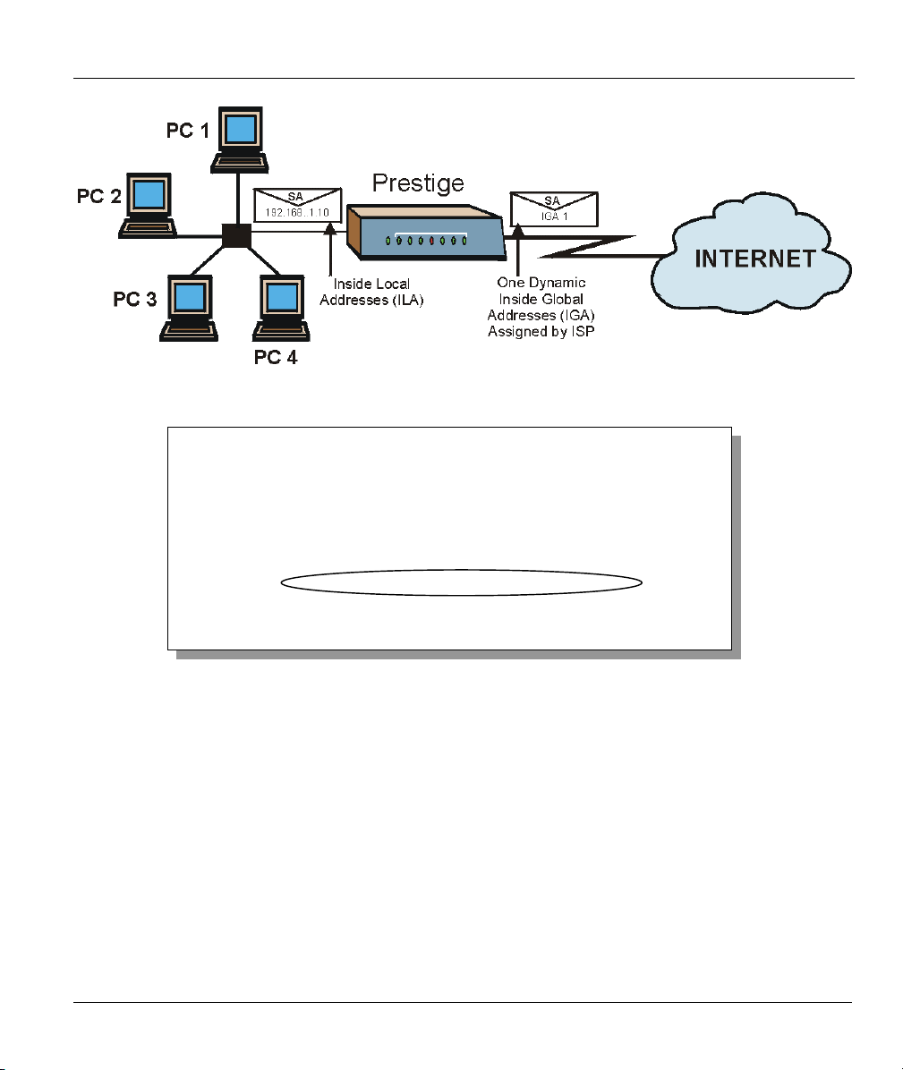
Figure 7-5 NAT Example 1
Prestige 650ME ADSL Bridge
ISP's Name= ChangeMe
Encapsulation= RFC-1483
Multiplexing= LLC-based
My Login= N/A
My Password= N/A
ENET ENCAP Gateway= N/A
IP Address Assignment= Static
IP Address= 0.0.0.0
Network Address Translation= SUA Only
Menu 4 - Internet Access Setup
Press ENTER to Confirm or ESC to Cancel:
Figure 7-6 Menu 4 – Internet Access & NAT Example
From menu 4, choose the SUA Only option from the Network Address Translation field. All your local
LAN IP addresses will be mapped to one WAN IP address on the WAN port.
NAT 7-7

Prestige 650ME ADSL Bridge
7.2.2 Example 2: Internet Access with an Inside Server
Figure 7-7 NAT Example 2
In this case, you do exactly as above (use the convenient pre-configured SUA Only set) and also go to
menu 15 to specify the Inside Server behind the NAT as shown in the next figure.
Rule Start Port No. End Port No. IP Address
---------------------------------------------------
1. Default Default 192.168.1.10
2. 0 0 0.0.0.0
3. 0 0 0.0.0.0
4. 0 0 0.0.0.0
5. 0 0 0.0.0.0
6. 0 0 0.0.0.0
7. 0 0 0.0.0.0
8. 0 0 0.0.0.0
9. 0 0 0.0.0.0
10. 0 0 0.0.0.0
11. 0 0 0.0.0.0
12. 0 0 0.0.0.0
Press ENTER to Confirm or ESC to Cancel:
Menu 15.2 - NAT Server Setup
Figure 7-8 Menu 15 – Specifying an Inside Server
7-8 NAT

Advanced Management
PPaarrtt IIIIII::
ADVANCED MANAGEMENT
This part discusses Filtering, SNMP, System Information and Diagnosis, Firmware and
Configuration File Maintenance, System Maintenance and Information, IP Policy Routing, Call
Scheduling and Remote Management.
III


Prestige 650ME ADSL Bridge
Chapter 8
Filter Configuration
This chapter shows you how to create and apply filters.
8.1 About Filtering
Your Prestige uses filters to decide whether or not to allow passage of a data packet and/or to make a call.
There are two types of filter applications: data filtering and call filtering. Filters are subdivided into device
and protocol filters, which are discussed later.
Data filtering screens data to determine if the packet should be allowed to pass. Data filters are divided into
incoming and outgoing filters, depending on the direction of the packet relative to a port. Data filtering can
be applied on either the WAN side or the Ethernet side. Call filtering is used to determine if a packet should
be allowed to trigger a call.
Outgoing packets must undergo data filtering before they encounter call filtering. Call filters are divided
into two groups, the built-in call filters and user-defined call filters. Your Prestige has built-in call filters
that prevent administrative, for example, RIP packets from triggering calls. These filters are always enabled
and not accessible to you. Your Prestige applies the built-in filters first and then the user-defined call filters,
if applicable, as shown next.
Filter Configuration 8-1

Prestige 650ME ADSL Bridge
No
Outgoing
Packet
Data
match
Match MatchMatch
Built-in
default
Call Filters
Call Filtering
No
match
User-defined
Call Filters
(if applicable)
No
match
Active Data
Initiate call
if line not up
Send packet
and reset
Idle Timer
Drop
packet
Drop packet
if line not up
Drop packet
if line not up
Or Or
Send packet
but do not reset
Idle Timer
Send packet
but do not reset
Idle Timer
Figure 8-1 Outgoing Packet Filtering Process
Two sets of factory filter rules have been configured in menu 21 to prevent NetBIOS traffic from triggering
calls. A summary of their filter rules is shown in the figures that follow.
The following figure illustrates the logic flow when executing a filter rule.
8-2 Filter Configuration

Filter Set
Prestige 650ME ADSL Bridge
Start
Packet
intoFilter
Fetch First
Filter Set
Fetch Next
Filter Set
Yes
Next Filter Set
Available?
No
Fetch Next
Filter Rule
Yes
No
Next filter
Rule
Available?
No
Filter Rule
Check
Next
Rule
Drop
Figure 8-2 Filter Rule Process
Fetch First
Filter Rule
Yes
Active?
Yes
Execute
Forward
Accept PacketDrop Packet
You can apply up to four filter sets to a particular port to block various types of packets. Because each filter
set can have up to six rules, you can have a maximum of 24 rules active for a single port.
Filter Configuration 8-3

Prestige 650ME ADSL Bridge
For incoming packets, your Prestige applies data filters only. Packets are processed depending on whether a
match is found. The following sections describe how to configure filter sets.
The Filter Structure of the Prestige
A filter set consists of one or more filter rules. Usually, you would group related rules, for example, all the
rules for NetBIOS, into a single set and give it a descriptive name. You can configure up to twelve filter
sets with six rules in each set, for a total of 72 filter rules in the system.
8.2 Configuring a Filter Set
To configure a filter set, follow the steps shown next.
Step 1. Enter 21 in the main menu to display Menu 21 – Filter Set Configuration.
Filter Filter
Set # Comments Set # Comments
------ ----------------- ------ ---------------- 1 NetBIOS_WAN 7 _______________
2 NetBIOS_LAN 8 _______________
3 TELNET_WAN 9 _______________
4 PPPoE 10 _______________
5 FTP_WAN 11 WebSet1
6 _______________ 12 WebSet2
Enter Filter Set Number to Configure= 0
Edit Comments= N/A
Press ENTER to Confirm or ESC to Cancel:
Menu 21 - Filter Set Configuration
Figure 8-3 Menu 21 – Filter Set Configuration
Step 2. Type the filter set to configure (no. 1 to 12) and press [ENTER]
.
Filter rule set 11 and 12 are used by the web configurator. Your custom
configuration will be replaced if you use rule 11 or 12.
Step 3. Type a descriptive name or comment in the Edit Comments field and press [ENTER].
8-4 Filter Configuration
 Loading...