

Page 1

Prestige 650M-6x
ADSL Modem
User's Guide
Version 3.40
November 2004
Page 2

Page 3

Prestige 650M-6x User’s Guide
Copyright
Copyright © 2004 by ZyXEL Communications Corporation.
The contents of this publication may not be reproduced in any part or as a whole, transcribed, stored in a
retrieval system, translated into any language, or transmitted in any form or by any means, electronic,
mechanical, magnetic, optical, chemical, photocopying, manual, or otherwise, without the prior written
permission of ZyXEL Communications Corporation.
Published by ZyXEL Communications Corporation. All rights reserved.
Disclaimer
ZyXEL does not assume any liability arising out of the application or use of any products, or software
described herein. Neither does it convey any license under its patent rights nor the patent rights of others.
ZyXEL further reserves the right to make changes in any products described herein without notice. This
publication is subject to change without notice.
Trademarks
ZyNOS (ZyXEL Network Operating System) is a registered trademark of ZyXEL Communications, Inc.
Other trademarks mentioned in this publication are used for identification purposes only and may be
properties of their respective owners.
ii Copyright
Page 4

Prestige 650M-6x User’s Guide
Federal Communications Commission
(FCC) Interference Statement
This device complies with Part 15 of FCC rules. Operation is subject to the following two conditions:
• This device may not cause harmful interference.
• This device must accept any interference received, including interference that may cause undesired
operations.
This equipment has been tested and found to comply with the limits for a Class B digital device pursuant to
Part 15 of the FCC Rules. These limits are designed to provide reasonable protection against harmful
interference in a commercial environment. This equipment generates, uses, and can radiate radio frequency
energy, and if not installed and used in accordance with the instructions, may cause harmful interference to
radio communications.
If this equipment does cause harmful interference to radio/television reception, which can be determined by
turning the equipment off and on, the user is encouraged to try to correct the interference by one or more of
the following measures:
1. Reorient or relocate the receiving antenna.
2. Increase the separation between the equipment and the receiver.
3. Connect the equipment into an outlet on a circuit different from that to which the receiver is connected.
4. Consult the dealer or an experienced radio/TV technician for help.
Notice 1
Changes or modifications not expressly approved by the party responsible for compliance could void the
user's authority to operate the equipment.
Certifications
1. Go to www.zyxel.com
2. Select your product from the drop-down list box on the ZyXEL home page to go to that product's page.
3. Select the certification you wish to view from this page
FCC Statement iii
Page 5

Prestige 650M-6x User’s Guide
ZyXEL Limited Warranty
ZyXEL warrants to the original end user (purchaser) that this product is free from any defects in materials
or workmanship for a period of up to two years from the date of purchase. During the warranty period, and
upon proof of purchase, should the product have indications of failure due to faulty workmanship and/or
materials, ZyXEL will, at its discretion, repair or replace the defective products or components without
charge for either parts or labor, and to whatever extent it shall deem necessary to restore the product or
components to proper operating condition. Any replacement will consist of a new or re-manufactured
functionally equivalent product of equal value, and will be solely at the discretion of ZyXEL. This warranty
shall not apply if the product is modified, misused, tampered with, damaged by an act of God, or subjected
to abnormal working conditions.
Note
Repair or replacement, as provided under this warranty, is the exclusive remedy of the purchaser. This
warranty is in lieu of all other warranties, express or implied, including any implied warranty of
merchantability or fitness for a particular use or purpose. ZyXEL shall in no event be held liable for indirect
or consequential damages of any kind of character to the purchaser.
To obtain the services of this warranty, contact ZyXEL's Service Center for your Return Material
Authorization number (RMA). Products must be returned Postage Prepaid. It is recommended that the unit
be insured when shipped. Any returned products without proof of purchase or those with an out-dated
warranty will be repaired or replaced (at the discretion of ZyXEL) and the customer will be billed for parts
and labor. All repaired or replaced products will be shipped by ZyXEL to the corresponding return address,
Postage Paid. This warranty gives you specific legal rights, and you may also have other rights that vary
from country to country.
Safety Warnings
1. To reduce the risk of fire, use only No. 26 AWG or larger telephone wire.
2. Do not use this product near water, for example, in a wet basement or near a swimming pool.
3. Avoid using this product during an electrical storm. There may be a remote risk of electric shock from
lightening.
iv ZyXEL Warranty
Page 6

Prestige 650M-6x User’s Guide
Customer Support
Please have the following information ready when you contact customer support.
• Product model and serial number.
• Warranty Information.
• Date that you received your device.
• Brief description of the problem and the steps you took to solve it.
SUPPORT E-MAIL TELEPHONE1 WEB SITE METHOD
LOCATION
WORLDWIDE
AMERICA
SALES E-MAIL FAX1 FTP SITE
support@zyxel.com.tw +886-3-578-3942 www.zyxel.com
sales@zyxel.com.tw
support@zyxel.com +1-800-255-4101
sales@zyxel.com
support@zyxel.de +49-2405-6909-0 www.zyxel.de GERMANY
sales@zyxel.de
support@zyxel.es +34 902 195 420 SPAIN
sales@zyxel.es
support@zyxel.dk +45 39 55 07 00 www.zyxel.dk DENMARK
sales@zyxel.dk
support@zyxel.no +47 22 80 61 80 www.zyxel.no NORWAY
sales@zyxel.no
+886-3-578-2439 ftp.zyxel.com
+1-714-632-0882
+1-714-632-0858 ftp.us.zyxel.com
+49-2405-6909-99
+33 (0)4 72 52 97 97 FRANCE info@zyxel.fr
+33 (0)4 72 52 19 20
+34 913 005 345
+45 39 55 07 07
+47 22 80 61 81
www.europe.zyxel.com
ftp.europe.zyxel.com
www.us.zyxel.com NORTH
www.zyxel.fr ZyXEL France
www.zyxel.es
ZyXEL Communications
REGULAR MAIL
ZyXEL Communications Corp.
6 Innovation Road II
Science Park
Hsinchu 300
Taiwan
ZyXEL Communications Inc.
1130 N. Miller St.
Anaheim
CA 92806-2001
U.S.A.
ZyXEL Deutschland GmbH.
Adenauerstr. 20/A2 D-52146
Wuerselen
Germany
1 rue des Vergers
Bat. 1 / C
69760 Limonest
France
Alejandro Villegas 33
1º, 28043 Madrid
Spain
ZyXEL Communications A/S
Columbusvej 5
2860 Soeborg
Denmark
ZyXEL Communications A/S
Nils Hansens vei 13
0667 Oslo
Norway
1
“+” is the (prefix) number you enter to make an international telephone call.
Customer Support v
Page 7

Prestige 650M-6x User’s Guide
LOCATION
SUPPORT E-MAIL TELEPHONE1 WEB SITE METHOD
SALES E-MAIL FAX1 FTP SITE
support@zyxel.se +46 31 744 7700 www.zyxel.se SWEDEN
sales@zyxel.se
support@zyxel.fi +358-9-4780-8411 www.zyxel.fi FINLAND
sales@zyxel.fi
+46 31 744 7701
+358-9-4780 8448
REGULAR MAIL
ZyXEL Communications A/S
Sjöporten 4, 41764 Göteborg
Sweden
ZyXEL Communications Oy
Malminkaari 10
00700 Helsinki
Finland
vi Customer Support
Page 8

Prestige 650M-6x User’s Guide
Table of Contents
Copyright.........................................................................................................................................................ii
Federal Communications Commission (FCC) Interference Statement.....................................................iii
ZyXEL Limited Warranty.............................................................................................................................iv
Customer Support........................................................................................................................................... v
List of Figures.................................................................................................................................................ix
List of Tables...................................................................................................................................................xi
List of Charts.................................................................................................................................................xii
Preface...........................................................................................................................................................xiii
Introduction to DSL...................................................................................................................................... xv
GETTING STARTED..................................................................................................................................... I
Chapter 1 Getting To Know Your Prestige.................................................................................................1-1
1.1 Introducing the Prestige .............................................................................................................1-1
1.2 Features of the Prestige ..............................................................................................................1-1
1.3 Applications for the Prestige......................................................................................................1-3
COMMANDS ................................................................................................................................................. II
Chapter 2 Commands Introduction ...........................................................................................................2-1
2.1 Command Line Overview..........................................................................................................2-1
2.2 Connect to your Prestige Using Telnet.......................................................................................2-2
2.3 Resetting the Prestige.................................................................................................................2-2
2.4 Changing the Password ..............................................................................................................2-2
2.5 Command Summary...................................................................................................................2-3
Chapter 3 System Setup...............................................................................................................................3-1
3.1 System Commands.....................................................................................................................3-1
Chapter 4 LAN Setup ..................................................................................................................................4-1
4.1 LAN Overview...........................................................................................................................4-1
4.2 LAN Configuration ....................................................................................................................4-2
Chapter 5 Ethernet Setup............................................................................................................................5-1
5.1 Ethernet Parameters ...................................................................................................................5-1
5.2 Ethernet Commands...................................................................................................................5-1
Chapter 6 Bridge Statistics..........................................................................................................................6-1
6.1 Bridging in General....................................................................................................................6-1
6.2 Bridge Ethernet Setup ................................................................................................................6-1
Chapter 7 WAN Setup .................................................................................................................................7-1
7.1 WAN IP Address Assignment....................................................................................................7-1
7.2 RFC 1483 ...................................................................................................................................7-1
7.3 Multiplexing...............................................................................................................................7-2
7.4 VPI and VCI...............................................................................................................................7-2
7.5 Introduction to ATM..................................................................................................................7-2
Table of Contents vii
Page 9

Prestige 650M-6x User’s Guide
7.6 Interleave Delay.........................................................................................................................7-4
7.7 G.Hs........................................................................................................................................... 7-4
7.8 SNR (Signal-to-Noise-Ratio).....................................................................................................7-4
7.9 Remote node Configuration.......................................................................................................7-5
7.10 ADSL Configuration..................................................................................................................7-9
Chapter 8 IP Configuration ........................................................................................................................8-1
8.1 IP Address.................................................................................................................................. 8-1
8.2 Introduction to ARP Table......................................................................................................... 8-2
8.3 About Ping .................................................................................................................................8-2
8.4 Ping Commands.........................................................................................................................8-3
8.5 Static Route Overview ............................................................................................................... 8-5
8.6 TCP/IP .......................................................................................................................................8-7
Chapter 9 Firmware Upload.......................................................................................................................9-1
9.1 Firmware Upload Overview.......................................................................................................9-1
9.2 Checking System Firmware Version .........................................................................................9-1
9.3 Uploading Firmware via Utility.................................................................................................9-1
APPENDICES AND INDEX........................................................................................................................III
Appendix A Troubleshooting...................................................................................................................... A-1
Appendix B Virtual Circuit Topology ....................................................................................................... B-1
Appendix C IP Subnetting .........................................................................................................................C-1
Appendix D Setting up Your Computer’s IP Address.............................................................................. D-1
Appendix E Index ....................................................................................................................................... E-1
viii Table of Contents
Page 10

Prestige 650M-6x User’s Guide
List of Figures
Figure 1-1 Prestige Internet Access Application ............................................................................................ 1-3
Figure 2-1 CLI Help Example –1................................................................................................................... 2-1
Figure 2-2 CLI Help Example -2 ................................................................................................................... 2-1
Figure 2-3 Login Screen ................................................................................................................................ 2-2
Figure 2-4 Password Changing ...................................................................................................................... 2-3
Figure 3-1 sys countrycode............................................................................................................................ 3-1
Figure 3-2 sys date ......................................................................................................................................... 3-1
Figure 3-3 sys edit.......................................................................................................................................... 3-2
Figure 3-4 sys feature..................................................................................................................................... 3-2
Figure 3-5 sys hostname ................................................................................................................................ 3-3
Figure 3-6 sys stdio........................................................................................................................................ 3-3
Figure 3-7 sys datetime period....................................................................................................................... 3-4
Figure 3-8 sys time......................................................................................................................................... 3-4
Figure 3-9 sys version.................................................................................................................................... 3-4
Figure 3-10 sys view...................................................................................................................................... 3-5
Figure 3-11 sys wdog switch.......................................................................................................................... 3-5
Figure 3-12 sys wdog cnt............................................................................................................................... 3-5
Figure 3-13 sys romreset................................................................................................................................ 3-5
Figure 3-14 sys atsh ....................................................................................................................................... 3-6
Figure 3-15 sys password............................................................................................................................... 3-6
Figure 3-16 sys password............................................................................................................................... 3-6
Figure 3-17 sys cpu display............................................................................................................................ 3-7
Figure 4-1 LAN and WAN IP Addresses ....................................................................................................... 4-1
Figure 4-2 lan index Example 1..................................................................................................................... 4-2
Figure 4-3 lan index Example 2..................................................................................................................... 4-2
Figure 4-4 lan ipaddr...................................................................................................................................... 4-3
Figure 4-5 lan display .................................................................................................................................... 4-3
Figure 4-6 lan clear ........................................................................................................................................ 4-3
Figure 4-7 lan save......................................................................................................................................... 4-4
Figure 5-1 ether status.................................................................................................................................... 5-2
Figure 5-2 ether config................................................................................................................................... 5-2
Figure 5-3 ether driver cnt disp...................................................................................................................... 5-3
Figure 5-4 sys password................................................................................................................................. 5-3
Figure 5-5 ether driver config ........................................................................................................................ 5-3
Figure 5-6 ether driver status ......................................................................................................................... 5-4
Figure 5-7 ether driver config ........................................................................................................................ 5-4
Figure 5-8 ether driver version....................................................................................................................... 5-5
Figure 6-1 bridge cnt disp .............................................................................................................................. 6-1
List of Figures ix
Page 11

Prestige 650M-6x User’s Guide
Figure 6-2 bridge cnt clear..............................................................................................................................6-2
Figure 6-3 bridge stat disp ..............................................................................................................................6-2
Figure 6-4 bridge stat clear ............................................................................................................................. 6-3
Figure 7-1 wan node index .............................................................................................................................7-5
Figure 7-2 wan node clear ..............................................................................................................................7-5
Figure 7-3 wan node save ...............................................................................................................................7-5
Figure 7-4 wan node ispname.........................................................................................................................7-6
Figure 7-5 wan node enable............................................................................................................................7-6
Figure 7-6 wan node disable...........................................................................................................................7-6
Figure 7-7 wan node encap.............................................................................................................................7-6
Figure 7-8 wan node display...........................................................................................................................7-7
Figure 7-9 wan node mux ...............................................................................................................................7-7
Figure 7-10 wan node vpi ...............................................................................................................................7-7
Figure 7-11 wan node vci ...............................................................................................................................7-8
Figure 7-12 wan node qos...............................................................................................................................7-8
Figure 7-13 wan node pcr ...............................................................................................................................7-8
Figure 7-14 wan node scr................................................................................................................................7-8
Figure 7-15 wan node mbs..............................................................................................................................7-9
Figure 7-16 wan adsl chandata .......................................................................................................................7-9
Figure 7-17 wan adsl close .............................................................................................................................7-9
Figure 7-18 wan adsl linedata near ............................................................................................................... 7-10
Figure 7-19 wan adsl linedata far..................................................................................................................7-10
Figure 7-20 wan adsl open............................................................................................................................7-10
Figure 7-21 wan adsl opencmd.....................................................................................................................7-10
Figure 7-22 wan adsl opmode.......................................................................................................................7-11
Figure 7-23 wan adsl rateadap...................................................................................................................... 7-11
Figure 7-24 wan adsl perfdata ......................................................................................................................7-11
Figure 7-25 wan adsl reset............................................................................................................................7-12
Figure 7-26 wan adsl status ..........................................................................................................................7-12
Figure 8-1 ip address ......................................................................................................................................8-1
Figure 8-2 ip arp status ...................................................................................................................................8-2
Figure 8-3 Ping Commands Example-1..........................................................................................................8-4
Figure 8-4 Ping Commands Example-2..........................................................................................................8-5
Figure 8-5 Example of Static Routing Topology ............................................................................................8-5
Figure 8-6 ip route status ................................................................................................................................8-6
Figure 8-7 ip route drop..................................................................................................................................8-6
Figure 8-8 ip route flush .................................................................................................................................8-7
Figure 8-9 ip route lookup ..............................................................................................................................8-7
Figure 8-10 ip tcp status..................................................................................................................................8-8
Figure 9-1 Version Command Example..........................................................................................................9-1
x List of Figures
Page 12

Prestige 650M-6x User’s Guide
List of Tables
Table 2-1 Command Summary ...................................................................................................................... 2-3
Table 3-1 sys feature ...................................................................................................................................... 3-2
Table 5-1 Service Characteristic .................................................................................................................... 5-4
Table 7-1 Private IP Address Ranges ............................................................................................................. 7-1
Table 7-2 Service Characteristic .................................................................................................................... 7-4
Table 8-1 Ping Commands............................................................................................................................. 8-3
List of Tables xi
Page 13

Prestige 650M-6x User’s Guide
List of Charts
Chart C-1 Classes of IP Addresses................................................................................................................. C-1
Chart C-2 Allowed IP Address Range By Class ............................................................................................C-2
Chart C-3 “Natural” Masks............................................................................................................................ C-2
Chart C-4 Alternative Subnet Mask Notation ................................................................................................ C-3
Chart C-5 Subnet 1 ........................................................................................................................................C-4
Chart C-6 Subnet 2 ........................................................................................................................................C-4
Chart C-7 Subnet 1 ........................................................................................................................................C-5
Chart C-8 Subnet 2 ........................................................................................................................................C-5
Chart C-9 Subnet 3 ........................................................................................................................................C-5
Chart C-10 Subnet 4 ......................................................................................................................................C-6
Chart C-11 Eight Subnets .............................................................................................................................. C-6
Chart C-12 Class C Subnet Planning............................................................................................................. C-7
Chart C-13 Class B Subnet Planning............................................................................................................. C-7
xii Lists of Charts
Page 14

Prestige 650M-6x User’s Guide
Preface
Congratulations on your purchase of the Prestige 650M-6x ADSL Modem.
Register your product online to receive e-mail notices of firmware upgrades and
information at www.zyxel.com for global products, or at www.us.zyxel.com for
North American products.
Your Prestige is easy to install and configure using CLI (Command Line Interface) commands.
Please visit our web site at www.zyxel.com
Don’t forget to register your Prestige (fast, easy online registration at
www.zyxel.com) for free future product updates and information.
About This User's Guide
This manual is designed to guide you through the configuration of your Prestige for its various applications.
Related Documentation
Supporting Disk
Refer to the included CD for support documents.
ZyXEL Web Site
The ZyXEL download library at www.zyxel.com
Please also refer to www.zyxel.com for an online glossary of networking terms.
Syntax Conventions
• “Type” means for you to type one or more characters and press the carriage return. “Select” or
“Choose” means for you to use one predefined choices. Command and arrow keys are enclosed in
square brackets. [ENTER] means the Enter, or carriage return key.
• For brevity’s sake, we will use “e.g.,” as shorthand for “for instance”, and “i.e.,” for “that is” or “in
other words” throughout this manual.
• The Prestige 650M-6x ADSL Modem series may be referred to as the Prestige in this user’s guide.
for the latest release notes and product information.
contains additional support documentation.
Preface xiii
Page 15

Prestige 650M-6x User’s Guide
Graphics Icons Key
Prestige
Server
Telephone
Wireless Signal
Computer
DSLAM
Switch
Notebook computer
Firewall
Router
The following section offers some background information on DSL. Skip to
Chapter 1 if you wish to begin working with your router right away.
xiv Preface
Page 16

Prestige 650M-6x User’s Guide
Introduction to DSL
DSL (Digital Subscriber Line) technology enhances the data capacity of the existing twisted-pair wire that
runs between the local telephone company switching offices and most homes and offices. While the wire
itself can handle higher frequencies, the telephone switching equipment is designed to cut off signals above
4,000 Hz to filter noise off the voice line, but now everybody is searching for ways to get more bandwidth to
improve access to the Web - hence DSL technologies.
There are actually seven types of DSL service, ranging in speeds from 16 Kbits/sec to 52 Mbits/sec. The
services are either symmetrical (traffic flows at the same speed in both directions), or asymmetrical (the
downstream capacity is higher than the upstream capacity). Asymmetrical services (ADSL) are suitable for
Internet users because more information is usually downloaded than uploaded. For example, a simple button
click in a web browser can start an extended download that includes graphics and text.
As data rates increase, the carrying distance decreases. That means that users who are beyond a certain
distance from the telephone company’s central office may not be able to obtain the higher speeds.
A DSL connection is a point-to-point dedicated circuit, meaning that the link is always up and there is no
dialing required.
Introduction to ADSL
It is an asymmetrical technology, meaning that the downstream data rate is much higher than the upstream
data rate. As mentioned, this works well for a typical Internet session in which more information is
downloaded, for example, from Web servers, than is uploaded. ADSL operates in a frequency range that is
above the frequency range of voice services, so the two systems can operate over the same cable.
Introduction to DSL xv
Page 17

Getting Started
Part I:
GETTING STARTED
This part is structured as a step-by-step guide to help you access your Prestige. It covers key
features and applications.
I
Page 18

Page 19

Prestige 650M-6x User’s Guide
Chapter 1
Getting To Know Your Prestige
This chapter describes the key features and applications of your Prestige.
1.1 Introducing the Prestige
Your Prestige integrates high-speed 10/100Mbps auto-negotiating LAN interface(s) and a high-speed ADSL
port into a single package. The Prestige is ideal for high-speed Internet browsing and making LAN-to-LAN
connections to remote networks.
Models ending in “1”, for example P650M-61, denote a device that works over the analog telephone system,
POTS (Plain Old Telephone Service). Models ending in “3” denote a device that works over ISDN
(Integrated Synchronous Digital System). Models ending in “7” denote a device that works over T-ISDN
(UR-2).
Only use firmware for your Prestige’s specific model. Refer to the label on the
bottom of your Prestige.
Your Prestige is easy to install and configure using CLI (Command Line Interface) commands.
1.2 Features of the Prestige
The following sections describe the features of the Prestige.
High Speed Internet Access
Your Prestige ADSL modem can support downstream transmission rates of up to 8Mbps and upstream
transmission rates of 832 Kbps.
10/100M Auto-negotiating Ethernet/Fast Ethernet Interface(s)
This auto-negotiation feature allows the Prestige to detect the speed of incoming transmissions and adjust
appropriately without manual intervention. It allows data transfer of either 10 Mbps or 100 Mbps in either
half-duplex or full-duplex mode depending on your Ethernet network.
Auto-Crossover (MDI/MDI-X) 10/100 Mbps Ethernet Interface(s)
These interfaces automatically adjust to either a crossover or straight-through Ethernet cable.
Getting To Know Your Prestige 1-1
Page 20

Prestige 650M-6x User’s Guide
Multiple PVC (Permanent Virtual Circuits) Support
Your Prestige supports up to 2 PVC’s.
ADSL Transmission Rate Standards
♦ Full-Rate (ANSI T1.413, Issue 2; G.dmt (G.992.1) with line rate support of up to 8 Mbps
downstream and 832 Kbps upstream.
♦ G.lite (G.992.2) with line rate support of up to 1.5Mbps downstream and 512Kbps upstream.
♦ Supports Multi-Mode standard (ANSI T1.413, Issue 2; G.dmt (G.992.1); G.lite (G992.2)).
♦ TCP/IP (Transmission Control Protocol/Internet Protocol) network layer protocol.
♦ ATM Forum UNI 3.1/4.0 PVC.
♦ Supports up to 2 PVCs (UBR, CBR, VBRrt, VBRnrt).
♦ Multiple Protocol over AAL5 (RFC 1483).
♦ RFC 1661.
♦ Extended-Reach ADSL (ER ADSL)
Networking Compatibility
Your Prestige is compatible with the major ADSL DSLAM (Digital Subscriber Line Access Multiplexer)
providers, making configuration as simple as possible for you.
Multiplexing
The Prestige supports VC-based and LLC-based multiplexing.
Encapsulation
The Prestige supports RFC 1483 encapsulation over ATM.
Network Management
♦ CLI (Command Line Interpreter)
♦ Remote Management via Telnet
♦ Syslog
♦ Telnet Support (Password-protected telnet access to internal configuration manager)
♦ firmware upgrade utility
1-2 Getting To Know Your Prestige
Page 21
Prestige 650M-6x User’s Guide
♦ Supports OAM F4/F5 loop-back, AIS and RDI OAM cells
Ease of Installation
Your Prestige is designed for quick, easy and intuitive installation. Its compact size and light weight make it
easy to position anywhere in your busy office.
1.3 Applications for the Prestige
Here is an example use for which the Prestige is well suited.
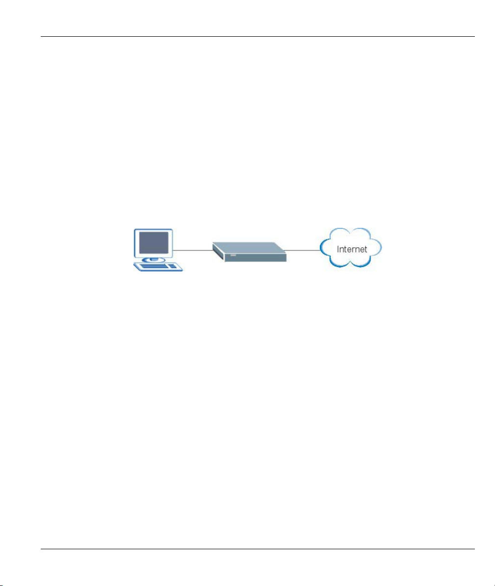
1.3.1 Internet Access
The Prestige is the ideal high-speed Internet access solution. Your Prestige supports the TCP/IP protocol,
which the Internet uses exclusively. A typical Internet access application is shown below.
Figure 1-1 Prestige Internet Access Application
Getting To Know Your Prestige 1-3
Page 22

Page 23

Commands
Part II:
COMMANDS
This part covers Commands Introduction, System, LAN, Ethernet, Bridge, WAN and IP Commands
and Firmware uploading.
II
Page 24

Page 25

Prestige 650M-6x User’s Guide
Chapter 2
Commands Introduction
This chapter describes how to access the Prestige and provides an overview of its commands.
2.1 Command Line Overview
You can use line commands to configure the Prestige. If you have problems with your Prestige, customer
support may request that you issue some of these commands to assist them in troubleshooting.
2.1.1 Command Syntax Conventions
1. Command keywords are in courier new font.
2. The / symbol means “or”.
3. Type “help” or “?” to display a list of valid commands or type a command (see Table 2-1 Command
Summary) to display a list of associated subcommands.
Copyright (c) 1994 - 2004 ZyXEL Communications Corp.
ras> ?
Valid commands are:
sys exit ether wan
ip bridge lan
ras>
Figure 2-1 CLI Help Example –1
ras> sys
countrycode date edit feature
hostname stdio datetime time
version view wdog romreset
atsh password socket cpu
ras>
Figure 2-2 CLI Help Example -2
2.1.2 Command Notation
The following notations denote user options:
[a/b/c/d...] or <a/b/c/d…>: Select and type the predefined default options.
[DEFAULT] or <DEFAULT>: Enter the value or predefined selection for this sub-command.
a.b.c.d: The option is a 4-byte dotted decimal value.
Commands Introduction 2-1
Page 26

Prestige 650M-6x User’s Guide
2.1.3 Exit
Type exit at the command prompt to disconnect from the Prestige.
2.2 Connect to your Prestige Using Telnet
The following procedure details how to telnet into your Prestige.
Step 1. Make sure your computer IP address and the Prestige IP address are on the same subnet. Refer to
the Setting Up Your Computer IP Address appendix.
Step 2. In Windows, click Start (usually in the bottom left corner), Run and then type “telnet
192.168.1.1” (the default IP address) and click OK.
Step 3. For your first login, enter “1234” in the Password field. As you type a password, the screen
displays an asterisk “ * ” for each character you type.
Step 4. After entering the correct password you can use the commands to do configuration.
Password: ****
Figure 2-3 Login Screen
2.3 Resetting the Prestige
If you forget your password or cannot access the Prestige, you will need to use the RESET button at the back
of the Prestige to reload the factory-default configuration file. This means that you will lose all
configurations that you had previously and the password will be reset to “1234”.
2.3.1 Using The Reset Button
Step 1. Make sure the PWR/SYS LED is on (not blinking).
Step 2. Press the RESET button for more than five seconds or until the PWR/SYS LED begins to blink
and then release it. When the PWR/SYS LED begins to blink, the defaults have been restored
and the Prestige restarts.
2.4 Changing the Password
It is highly recommended that you change the password for accessing the Prestige.
Change the Prestige default password by using the command shown next. Make sure you store the password
in a safe place.
Syntax:
sys password <new password>
2-2 Commands Introduction
Page 27

Prestige 650M-6x User’s Guide
ras> sys password 5678
save ok
ras>
Figure 2-4 Password Changing
2.5 Command Summary
The following table is a summary of the commands available in the Prestige together with a brief description
of each command.
Table 2-1 Command Summary
MAIN
COMMAND
exit This command logs out the prestige.
sys
countrycode This command shows the country code of the
date This command shows the current system date.
edit <filename> This command edits a text file.
feature This command lists Prestige features.
hostname <hostname> This command shows the system hostname.
stdio This command shows or sets how many minutes the
datetime period This command shows or sets how many days
time This command shows the current system time.
version This command shows the firmware version and RAS
view <filename> This command views a text file.
wdog switch [on|off] This command turn on/off watchdog.
cnt This command shows watchdog count value.
romreset This command restores the factory defaults of your
atsh This command shows the factory default data.
SUB-COMMAND DESCRIPTION
firmware.
terminal can be left idle before the session times out.
(between 1 and 30) elapses before the Prestige
synchronizes with a time server.
code.
Prestige.
Commands Introduction 2-3
Page 28

Prestige 650M-6x User’s Guide
Table 2-1 Command Summary
MAIN
COMMAND
password <new password> This command sets the new password.
socket This command shows system socket information.
cpu display This command shows CPU utilization.
ether
config This command shows LAN settings.
driver cnt disp <name> This command shows Ethernet driver counters.
Status <ch-name> This command shows LAN status.
config This command sets MAC phy mode.
version This command shows Ethernet device type.
wan
node index [1~2] Use this command to set a remote node as the
clear This command clears the current nodes statistics
save This command saves the current nodes settings.
ispname <name> Use this command to identify the ISP used by this
enable This command enables the currently selected remote
disable This command disables the currently selected remote
encap <1483 > Use this command to set the method of
disp This command displays the settings for the current
mux <llc|vc> Use this command to set the multiplexing method
Vpi <vpi> Enter the Virtual Path Identifier from 0 to 255.
SUB-COMMAND DESCRIPTION
[0|1=auto|normal] [0|1=10|100]
[0|1=HD|FD] <ch-name>
current node to apply node commands.
node.
node.
node.
encapsulation used by the Prestige.
node.
used by the Prestige.
2-4 Commands Introduction
Page 29

Prestige 650M-6x User’s Guide
Table 2-1 Command Summary
MAIN
COMMAND
vci [num] Enter the Virtual Channel Identifier from 32 to 65535.
qos [ubr|cbr|vbr] This is the ATM QoS type.
pcr [num] This is the maximum rate at which the sender can
scr [num] This is the mean cell rate of each bursty traffic
mbs [num] This is the maximum number of cells that can be sent
bridge <on|off> Use this command to select have the Prestige act as
routeip <on|off> Use this command to select have the Prestige act as
hwsar disp This command displays hwsar packets
clear This command clears hwsar packets information.
adsl chandata This command displays the ADSL line channel
opmode This command displays the operating mode of the
linedata far Show ADSL far end noise margin
near Show ADSL near end noise margin
perfdata Show performance information, CRC, FEC, error
rateadap on Turn on rate adaptive mechanism
off Turn off rate adaptive mechanism
reset Reset ADSL modem, and must reload the modem
status ADSL status (ex: up, down or wait for init)
open Initialize ADSL connection
SUB-COMMAND DESCRIPTION
send cells.
source.
at the PCR.
a bridge.
a router.
incoming/outgoing information.
information.
ADSL line.
seconds.
code again
Commands Introduction 2-5
Page 30

Prestige 650M-6x User’s Guide
Table 2-1 Command Summary
MAIN
COMMAND
opencmd gdmt Open ADSL line with G.dmt standard
multimode Open ADSL line in multi modes
close Close ADSL line
targetnoise Adjust target noise offset
modem_code Display modem code version.
IP
address [xxx.xxx.x.x] This command sets or displays the current IP
arp status This command displays arp port statistics of your
ifconfig This command
ping<hostid> Packet Internet Groper is a protocol that sends out
route status This command displays the routing information for
add <dest addr>[/<bits>]
drop <host addr> [/<bits>] Use this command to delete an entry in the routing
status This command displays IP routing statistics.
tcp This command displays tcp statistics.
ceiling <value> TCP maximum round trip time.
floor <value> TCP minimum rtt.
kick <tcb> Kicks Transmission Control Block (TCB).
irtt<value> TCP default init rtt.
limit <value> Sets TCP output window limit.
mss <size> Maximum Segment Size.
SUB-COMMAND DESCRIPTION
address of your Prestige.
Prestige.
ICMP echo requests to test whether or not a remote
host is reachable.
static (manually entered) routes.
Use this command to add a static route to the routing
<gateway> [<metric>]
table.
table.
2-6 Commands Introduction
Page 31

Prestige 650M-6x User’s Guide
Table 2-1 Command Summary
MAIN
COMMAND
reset <tcb> Resets TCB.
rtt Sets round trip time for tcb.
status Display TCP statistic counters.
syndata [on|off] TCP syndata piggyback.
trace [on|off] Turn on/off trace for debugging.
window [size] TCP input window size.
Bridge
cnt disp <channel> This command displays the connection statistics for a
clear<channel> This command erases the connection statistics for
stat disp This command displays the packet statistics for a
clear This command erases the packet statistics for the
Lan
index <1:main LAN> Use this command to select an interface for editing or
ipaddr<IP Addr> <Mask> Use this command to display the IP address and
display This command displays the selected interface
clear This command erases the IP address and subnet
save After changing the interface fields save your settings
SUB-COMMAND DESCRIPTION
specified channel.
the specified channel.
specified channel.
specified channel.
display.
subnet mask for the selected interface.
settings.
mask settings for the selected interface.
back to the Prestige to keep them after reboot.
Commands Introduction 2-7
Page 32

Page 33

Prestige 650M-6x User’s Guide
Chapter 3
System Setup
This chapter provides the information on system configuration.
3.1 System Commands
Syntax:
sys countrycode [0-255]
This command sets the country code, the default is already set. If you need to change the country code,
contact your vendor for a list of valid codes.
An example is shown next.
Syntax:
sys date
This command shows the current system date. To set the date set the Prestige to update from the time server,
see Figure 3-7.
An example is shown next.
ras> sys countrycode 225
ras> sys countrycode
country code = 225
ras>
Figure 3-1 sys countrycode
ras> sys date
Current date is Thu 2004/08/01
ras>
Figure 3-2 sys date
Syntax:
sys edit<filename>
This command edits a text file. Currently you can edit the autoexec.net file stored in the Prestige. This file is
run on startup. Edit this file to automate commands that you want to execute every time you start the device.
System Setup 3-1
Page 34

Prestige 650M-6x User’s Guide
An example is shown next.
ras> sys edit autoexec.net
EDIT cmd: q(uit) x(save & exit) i(nsert after) d(elete)
r(eplace) n(ext)
dir
: sys dir
ras> sys view autoexec.net
sys dir
ip tcp mss 512
ip tcp limit 2
ip tcp irtt 65000
ip tcp window 2
ip tcp ceiling 6000
ras>
Figure 3-3 sys edit
Syntax:
sys feature
This command lists the hardware features of the Prestige.
An example is shown next.
ras> sys feature
IPX: no
IP ONLY: yes
AUI: yes
AB ADAPTER: no
IDSL ONLY: no
IDSL: no
INTERNAL HUB: no
ras>
Figure 3-4 sys feature
The following table describes the fields in this screen.
Table 3-1 sys feature
FIELD DESCRIPTION
IPX: no This Prestige doesn’t support the IPX protocol.
IP ONLY: yes This Prestige uses IP protocol.
AUI: yes This Prestige has a LAN port.
3-2 System Setup
Page 35

Prestige 650M-6x User’s Guide
Table 3-1 sys feature
FIELD DESCRIPTION
AB ADAPTER: no This Prestige does not have an internal phone connection.
IDSL ONLY: no This Prestige does not support IDSL.
IDSL: no This Prestige does not support IDSL.
INTERNAL HUB: no This Prestige has one Ethernet port.
Syntax:
sys hostname <hostname>
This command shows/sets the system hostname. Type a name using 9 characters or less to identify your
Prestige on the network. The hostname is also shown in the command prompt.
An example is shown next.
ras> sys hostname test
test> sys hostname
test
Figure 3-5 sys hostname
Syntax:
sys stdio
This command shows or sets how many minutes the terminal can be left idle before the session times out.
An example is shown next.
ras> sys stdio 25
Current Stdio Timeout = 25 minutes
Figure 3-6 sys stdio
Syntax:
sys datetime period
This command shows or sets how many days (between 1 and 30) elapses before the Prestige synchronizes
with a time server.
System Setup 3-3
Page 36

Prestige 650M-6x User’s Guide
ras> sys datetime period
The period to synchronize with time server is 1 day(s).
Figure 3-7 sys datetime period
Syntax:
sys time
This command shows the current system time.
An example is shown next.
ras> sys time
Current time is 00:13:24
Figure 3-8 sys time
Syntax:
sys version
This command shows the firmware version and RAS code.
An example is shown next.
ras> sys version
ZyNOS version: V3.40(SN.0)b2 | 7/9/2004
romRasSize: 458764
system up time: 0:18:23 (1af12 ticks)
bootbase version: V1.00 | 6/14/2004
Figure 3-9 sys version
Syntax:
sys view <filename>
This command views a text file. View the autoexec.net file to see the system defaults, or check your edits.
An example is shown next.
3-4 System Setup
Page 37

Prestige 650M-6x User’s Guide
ras> sys view autoexec.net
ip tcp mss 512
ip tcp limit 2
ip tcp irtt 65000
ip tcp window 2
ip tcp ceiling 6000
ras>
Figure 3-10 sys view
Syntax:
sys wdog switch [on|off]
This command turns on/off watchdog.
An example is shown next.
ras> sys wdog switch on
Figure 3-11 sys wdog switch
Syntax:
sys wdog switch cnt
This command shows watchdog count value.
An example is shown next.
ras> sys wdog cnt
Max Miss: 180
Figure 3-12 sys wdog cnt
Syntax:
sys romreset
This command restores the factory defaults of your Prestige.
An example is shown next.
ras> sys romreset
Do you want to restore default ROM file(y/n)?n
canceled
Figure 3-13 sys romreset
Syntax:
sys atsh
This command shows the factory default data.
System Setup 3-5
Page 38

Prestige 650M-6x User’s Guide
An example is shown next.
ras> sys atsh
RAS version : V3.40(SN.0)b2 | 7/9/2004
Ram Size : 2048 Kbytes
Flash Type and Size : AMD 4Mbits*1
romRasSize : 458764
bootbase version : V1.00 | 6/14/2004
Product Model : Prestige 650M-67
MAC Address : 00A0C59C7B83
Default Country Code : FF
Boot Module Debug Flag : 00
RomFile Version : 17
RomFile Checksum : 3e31
RAS F/W Checksum : a2f1
SNMP MIB level & OID :
060102030405060708091011121314151617181920
Main Feature Bits : C0
Other Feature Bits :
92 63 00 00 00 00 00 00 00 00 00 00 00 00 00 00
00 00 00 00 00 00 00 00 00 41 13 00 00 00
Figure 3-14 sys atsh
Syntax:
sys password
This command sets the new password. It is highly recommended that you change the password for accessing
the Prestige
An example is shown next.
ras> sys password 1234
save ok
Figure 3-15 sys password
Syntax:
sys socket
This command shows system socket information.
An example is shown next.
ras> sys socket
S# Type PCB Remote socket Owner
8192 TCP 94112820 192.168.1.22:1033 940f70cc PP0f
Figure 3-16 sys password
3-6 System Setup
Page 39

Syntax:
sys cpu display
This command shows CPU utilization.
An example is shown next.
ras> sys cpu display
CPU usage status:
baseline 872865 ticks
sec ticks util sec ticks util sec ticks util sec ticks util
0 867922 0.56 1 865527 0.84 2 868346 0.51 3 869880 0.34
4 869049 0.43 5 868230 0.53 6 872145 0.08 7 872130 0.08
8 872154 0.08 9 872151 0.08 10 872151 0.08 11 872151 0.08
12 872088 0.08 13 871744 0.12 14 871914 0.10 15 872154 0.08
16 872155 0.08 17 872120 0.08 18 872154 0.08 19 872158 0.08
20 872156 0.08 21 872156 0.08 22 872156 0.08 23 872123 0.08
24 871868 0.11 25 872160 0.08 26 872158 0.08 27 872148 0.08
28 872160 0.08 29 872161 0.08 30 872160 0.08 31 872136 0.08
32 872165 0.08 33 872139 0.08 34 872140 0.08 35 872141 0.08
36 872140 0.08 37 872124 0.08 38 872140 0.08 39 872140 0.08
40 872145 0.08 41 872143 0.08 42 872142 0.08 43 872148 0.08
44 872144 0.08 45 872144 0.08 46 872143 0.08 47 872130 0.08
48 872149 0.08 49 872148 0.08 50 872147 0.08 51 872150 0.08
52 872148 0.08 53 872149 0.08 54 872148 0.08 55 872149 0.08
56 872153 0.08 57 872138 0.08 58 872152 0.08 59 872155 0.08
60 872152 0.08 61 872153 0.08 62 872151 0.08
Prestige 650M-6x User’s Guide
Figure 3-17 sys cpu display
System Setup 3-7
Page 40

Page 41

Prestige 650M-6x User’s Guide
Chapter 4
LAN Setup
This chapter provides the information on LAN configuration.
4.1 LAN Overview
A Local Area Network (LAN) is a shared communication system to which many computers are attached. A
LAN is a computer network limited to the immediate area, usually the same building or floor of a building..
4.1.1 LANs, WANs and the Prestige
The actual physical connection determines whether the Prestige ports are LAN or WAN ports. There are two
separate IP networks, one inside the LAN network and the other outside the WAN network as shown next:
Figure 4-1 LAN and WAN IP Addresses
4.1.2 Multicast
Traditionally, IP packets are transmitted in one of either two ways - Unicast (1 sender - 1 recipient) or
Broadcast (1 sender - everybody on the network). Multicast delivers IP packets to a group of hosts on the
network - not everybody and not just 1.
IGMP (Internet Group Multicast Protocol) is a network-layer protocol used to establish membership in a
Multicast group - it is not used to carry user data. IGMP version 2 (RFC 2236) is an improvement over
version 1 (RFC 1112) but IGMP version 1 is still in wide use. If you would like to read more detailed
LAN Setup 4-1
Page 42

Prestige 650M-6x User’s Guide
information about interoperability between IGMP version 2 and version 1, please see sections 4 and 5 of
RFC 2236. The class D IP address is used to identify host groups and can be in the range 224.0.0.0 to
239.255.255.255. The address 224.0.0.0 is not assigned to any group and is used by IP multicast computers.
The address 224.0.0.1 is used for query messages and is assigned to the permanent group of all IP hosts
(including gateways). All hosts must join the 224.0.0.1 group in order to participate in IGMP. The address
224.0.0.2 is assigned to the multicast routers group.
The Prestige supports both IGMP version 1 (IGMP-v1) and IGMP version 2 (IGMP-v2). At start up, the
Prestige queries all directly connected networks to gather group membership. After that, the Prestige
periodically updates this information.
4.2 LAN Configuration
Syntax:
lan index <1:main LAN>
Use this command to select an interface for editing or display.
An example is shown next.
ras> lan index 2
Nothing Selected
Figure 4-2 lan index Example 1
Currently there is only one interface available to select.
ras> lan index 1
enif0 is selected
ras>
Figure 4-3 lan index Example 2
4-2 LAN Setup
Page 43

Prestige 650M-6x User’s Guide
Syntax:
lan ipaddr<IP Addr> <Mask>
Use this command to display the IP address and subnet mask for the selected interface.
An example is shown next.
ras> lan ipaddr 192.168.1.2 255.255.255.0
ras> lan display
Active: Yes
Interface: enif0
IP Address: 192.168.1.2
Subnet Mask: 255.255.255.0
Figure 4-4 lan ipaddr
After changing the interface fields you need to save your settings back to the
Prestige to keep them after reboot.
Syntax:
lan display
This command displays the selected interface settings.
An example is shown next.
ras> lan display
Active: Yes
Interface: enif0
IP Address: 192.168.1.2
Subnet Mask: 255.255.255.0
Figure 4-5 lan display
Syntax:
lan clear
This command erases the IP address and subnet mask settings for the selected interface.
An example is shown next.
ras> lan clear
ras> lan display
Active: Yes
Interface: enif0
IP Address: 0.0.0.0
Subnet Mask: 0.0.0.0
Figure 4-6 lan clear
LAN Setup 4-3
Page 44

Prestige 650M-6x User’s Guide
Syntax:
lan save
This command erases the IP address and subnet mask settings for the selected interface.
An example is shown next.
ras> lan clear
ras> lan display
Active: Yes
Interface: enif0
IP Address: 0.0.0.0
Subnet Mask: 0.0.0.0
Figure 4-7 lan save
4-4 LAN Setup
Page 45

Prestige 650M-6x User’s Guide
Chapter 5
Ethernet Setup
This chapter provides the information on Ethernet configuration.
5.1 Ethernet Parameters
5.1.1 Speed
When auto-negotiation is turned on, an Ethernet port negotiates with the peer automatically to determine the
connection speed and duplex mode. If the peer Ethernet port does not support auto-negotiation or turns off
this feature, the device determines the connection speed by detecting the signal on the cable and using half
duplex mode. When the device’s auto-negotiation is turned off, an Ethernet port uses the pre-configured
speed and duplex mode when making a connection, thus requiring you to make sure that the settings of the
peer Ethernet port are the same in order to connect.
5.1.2 Duplex Mode
Duplex mode choices are half duplex or full duplex. When auto-negotiation is turned on, the Ethernet port on
the device negotiates with the peer automatically to determine the connection speed and duplex mode. When
a port is in half-duplex mode, it can either send data or receive data at a given time. When a port is in fullduplex mode, it can simultaneously send and receive data, effectively doubling its throughput.
5.1.3 Flow Control
A concentration of traffic on a port decreases port bandwidth and overflows buffer memory causing packet
discards and frame losses. Flow Control is used to regulate transmission of signals to match the bandwidth of
the receiving port.
The Prestige uses IEEE802.3x flow control in full duplex mode and back pressure flow control in half duplex
mode.
IEEE802.3x flow control is used in full duplex mode to send a pause signal to the sending port, causing it to
temporarily stop sending signals when the receiving port memory buffers fill.
Back pressure flow control is typically used in half duplex mode to send a "collision" signal to the sending
port (mimicking a state of packet collision) when the receiving port memory buffers are full causing the
sending port to temporarily stop sending signals and resend later.
5.2 Ethernet Commands
Syntax:
ether driver status
Ethernet Setup 5-1
Page 46

Prestige 650M-6x User’s Guide
This command displays the current status of the Ethernet ports.
ras> ether driver status enet0
ChanID = 0, Mac = 00:a0:c5:9c:7b:83
eq = 0, dq = 0
ifaceType = 0, TxSending = 0
mac_p = 940d2a4c, ec_p = 94147058
LinkSt = 7, CacheQueue = 0
MbufCacheAlloc = 0, MbufCacheEmpty = 0
Reset counts = 0, Phy address = 1f
txUnReleasedBufCnt = 12
Figure 5-1 ether status
Syntax:
ether config
This command shows LAN settings.
An example is shown next.
ras> ether config
--------------- NDIS CONFIGURATION BLOCK ---------------type=1 flags=0001
Board/Chassis:1 Lines/Board:1 Channels/Lines:1 Total Channel:1
task-id=940f6ba8 event-q=94121940(18) data-q=94121984(19) funcid=2
board-cfg=940fc794 line-cfg=940fc7ac chann-cfg=940fc7c0
board-pp (940fc7d0)
940fc29c
line-pp (940fc7d4)
940fc594
chann-pp (940fc7d8)
94147058
--------------- BOARD DISPLAY --------------------------ID slot# n-line n-chann status line-cfg chann-cfg
00 0 1 1 0001 940fc7ac 940fc7c0
--------------- LINE DISPLAY --------------------------ID line# board-id n-chann chann-cfg
00 1 00 1 940fc7c0
--------------- CHANNEL DISPLAY ------------------------ID chan# line-id board-id address name
00 1 00 00 94147058 enet0
Figure 5-2 ether config
Syntax:
ether driver cnt disp <name>
This command shows Ethernet driver counters.
An example is shown next.
5-2 Ethernet Setup
Page 47

Prestige 650M-6x User’s Guide
ras> ether driver cnt disp enet0
[ Ethernet Statistics Display, ChanID = 0 ]
inOctets = 0x0001ac7a, inUnicastPkts = 0x00000580
inMulticastPkts = 0x000000bd, inDiscards = 0x00000000
inErrors = 0x00000000, inAll = 0x0000063d
outOctets = 0x00020cb1, outUnicastPkts = 0x00000847
outMulticastPkts = 0x00000001, outDiscards = 0x00000000
outErrors = 0x00000000, outAll = 0x00000848
[ inSilicon Statistics Display ]
txJabberTimeCnt = 0x00000000, txLossOfCarrierCnt = 0x00000000
txNoCarrierCnt = 0x00000000, txLateCollisionCnt = 0x00000000
txExCollisionCnt = 0x00000000, txHeartbeatFailCnt = 0x00000000
txCollisionCnt = 0x00000000, txExDeferralCnt = 0x00000000
txUnderRunCnt = 0x00000000, rxAlignErr = 0x00000000
rxSymbolErr = 0x00000000, rxMiiErr = 0x00000000
rxCrcErr = 0x00000000, rxLengthErr = 0x00000000
rxDribblingErr = 0x00000000, rxRuntErr = 0x00000000
rxCollisionErr = 0x00000000, rxCodeErr = 0x00000000
Figure 5-3 ether driver cnt disp
Syntax:
ether driver status <ch-name>
This command shows LAN status.
An example is shown next.
ras> ether driver status enet0
ChanID = 0, Mac = 00:a0:c5:9c:7b:83
eq = 0, dq = 0
ifaceType = 0, TxSending = 0
mac_p = 940d2a4c, ec_p = 94147058
LinkSt = 7, CacheQueue = 0
MbufCacheAlloc = 0, MbufCacheEmpty = 0
Reset counts = 0, Phy address = 1f
txUnReleasedBufCnt = 10
Figure 5-4 sys password
Syntax:
ether driver config [0|1=auto|normal] [0|1=10|100] [0|1=HD|FD] <chname>
This command sets MAC phy mode.
An example is shown next.
ras> ether driver config 1 1 0 enet0
Figure 5-5 ether driver config
Ethernet Setup 5-3
Page 48

Prestige 650M-6x User’s Guide
Syntax:
ether driver status <ch-name>
This command shows LAN status.
An example is shown next.
ras> ether driver status enet0
ChanID = 0, Mac = 00:a0:c5:9c:7b:83
eq = 0, dq = 0
ifaceType = 0, TxSending = 0
mac_p = 940d2a4c, ec_p = 94147058
LinkSt = 7, CacheQueue = 0
MbufCacheAlloc = 0, MbufCacheEmpty = 0
Reset counts = 0, Phy address = 1f
txUnReleasedBufCnt = 10
Figure 5-6 ether driver status
Syntax:
ether driver config [0|1=auto|normal] [0|1=10|100] [0|1=HD|FD] <chname>
This command sets MAC phy mode.
An example is shown next.
ras> ether driver config 0 0 0 enet0
Figure 5-7 ether driver config
Table 5-1 Service Characteristic
FIELD DESCRIPTION
auto|normal When auto-negotiation is turned on, an Ethernet port negotiates with the peer
automatically to determine the connection speed and duplex mode. See section
5.1.1 for more information.
10|100 Manually set the connection speed to 10Mbps or 100Mbps.
HD|FD Select either Half Duplex or Full-Duplex, see section 5.1.2 for more information.
<ch-name> Specify an Ethernet channel to apply your settings. Currently only one enet0 is
supported.
5-4 Ethernet Setup
Page 49

Syntax:
ether driver version
This command shows the Ethernet device type.
An example is shown next.
ras> ether version
ether: V1.00
Figure 5-8 ether driver version
Prestige 650M-6x User’s Guide
Ethernet Setup 5-5
Page 50

Page 51

Prestige 650M-6x User’s Guide
Chapter 6
Bridge Statistics
This chapter provides the information on bridge connection and packet statistics
6.1 Bridging in General
Bridging bases the forwarding decision on the MAC (Media Access Control), or hardware address, while
routing does it on the network layer (IP) address. Bridging allows the Prestige to transport packets of network
layer protocols that it does not route, for example, SNA, from one network to another. The caveat is that,
compared to routing, bridging generates more traffic for the same network layer protocol, and it also
demands more CPU cycles and memory.
For efficiency reasons, do not turn on bridging unless you need to support protocols other than IP on your
network. For IP, enable the routing if you need it; do not bridge what the Prestige can route.
6.2 Bridge Ethernet Setup
Basically, all non-local packets are bridged to the WAN. Your Prestige does not support IPX.
Syntax:
bridge cnt disp <channel>
This command displays the connection statistics for a specified channel.
An example is shown next.
ras> bridge cnt disp 1
***Last Bridge Route Code 10
WanLanIdErr 0 WanMacHdrErr 0
WanFiltered 0 WanQueLanErr 0
LanMacHdrErr 0 LanFiltered 0
LanWatchDogQueErr 0 LanNotBrtNotCast 0
LanNoWanDevice 0 LanNoNode 0
LanNoDialOnCast 27 LanDial 0
LanDialNotAllow 0 BrCastIPNotSent 0
BrCastIPXNotSent 0 BrCastATNotSent 0
BrtDial 0 BrtDialNotAllow 0
WanNoNode 0 BrtAddLocalNode 0
Figure 6-1 bridge cnt disp
Bridge Statistics 6-1
Page 52

Prestige 650M-6x User’s Guide
Syntax:
bridge cnt clear <channel>
This command erases the connection statistics for the specified channel.
An example is shown next.
ras> bridge cnt clear 1
ras> bridge cnt disp 1
***Last Bridge Route Code 10
WanLanIdErr 0 WanMacHdrErr 0
WanFiltered 0 WanQueLanErr 0
LanMacHdrErr 0 LanFiltered 0
LanWatchDogQueErr 0 LanNotBrtNotCast 0
LanNoWanDevice 0 LanNoNode 0
LanNoDialOnCast 0 LanDial 0
LanDialNotAllow 0 BrCastIPNotSent 0
BrCastIPXNotSent 0 BrCastATNotSent 0
BrtDial 0 BrtDialNotAllow 0
WanNoNode 0 BrtAddLocalNode 0
Figure 6-2 bridge cnt clear
Syntax:
bridge stat disp <channel>
This command displays the packet statistics for a specified channel.
An example is shown next.
ras> bridge stat disp 1
***Last Bridge Pkt code 17
WanInIP 0 WanInIPX 0
WanInARP 0 WanInATLK 0
WanInOTHR 0 WanInIPbrCast 0
WanInIPXbrCast 0 WanInARPbrCast 0
WanInATLKbrCast 0 WanInOTHRbrCast 0
LanInIP 0 LanInIPX 0
LanInARP 0 LanInATLK 0
LanInOTHR 0 LanInIPbrCast 14
LanInIPXbrCast 10 LanInARPbrCast 2
LanInATLKbrCast 0 LanInOTHRbrCast 0
LanInWatchDog 0 WanInOdd 0
WanInWanOut 0 WanInOwn 0
WanInLanOut 0 LanInWanOut 0
LanInWanOut2 0
Figure 6-3 bridge stat disp
6-2 Bridge Statistics
Page 53

Syntax:
bridge stat clear <channel>
This command erases the packet statistics for a specified channel.
An example is shown next.
ras> bridge stat clear 1
ras> bridge stat disp 1
***Last Bridge Pkt code 17
WanInIP 0 WanInIPX 0
WanInARP 0 WanInATLK 0
WanInOTHR 0 WanInIPbrCast 0
WanInIPXbrCast 0 WanInARPbrCast 0
WanInATLKbrCast 0 WanInOTHRbrCast 0
LanInIP 0 LanInIPX 0
LanInARP 0 LanInATLK 0
LanInOTHR 0 LanInIPbrCast 0
LanInIPXbrCast 0 LanInARPbrCast 0
LanInATLKbrCast 0 LanInOTHRbrCast 0
LanInWatchDog 0 WanInOdd 0
WanInWanOut 0 WanInOwn 0
WanInLanOut 0 LanInWanOut 0
LanInWanOut2 0
Figure 6-4 bridge stat clear
Prestige 650M-6x User’s Guide
Bridge Statistics 6-3
Page 54

Page 55

Prestige 650M-6x User’s Guide
Chapter 7
WAN Setup
This chapter provides the information on WAN configuration.
7.1 WAN IP Address Assignment
Every computer on the Internet must have a unique IP address. If your networks are isolated from the
Internet, for instance, only between your two branch offices, you can assign any IP addresses to the hosts
without problems. However, the Internet Assigned Numbers Authority (IANA) has reserved the following
three blocks of IP addresses specifically for private networks.
Table 7-1 Private IP Address Ranges
10.0.0.0 - 10.255.255.255
172.16.0.0 - 172.31.255.255
192.168.0.0 - 192.168.255.255
You can obtain your IP address from the IANA, from an ISP or have it assigned by a private network. If you
belong to a small organization and your Internet access is through an ISP, the ISP can provide you with the
Internet addresses for your local networks. On the other hand, if you are part of a much larger organization,
you should consult your network administrator for the appropriate IP addresses.
Regardless of your particular situation, do not create an arbitrary IP address;
always follow the guidelines above. For more information on address assignment,
please refer to RFC 1597, Address Allocation for Private Internets and RFC 1466,
Guidelines for Management of IP Address Space.
7.2 RFC 1483
RFC 1483 describes two methods for Multiprotocol Encapsulation over ATM Adaptation Layer 5 (AAL5).
The first method allows multiplexing of multiple protocols over a single ATM virtual circuit (LLC-based
multiplexing) and the second method assumes that each protocol is carried over a separate ATM virtual
circuit (VC-based multiplexing). Please refer to the RFC for more detailed information.
WAN Setup 7-1
Page 56

Prestige 650M-6x User’s Guide
7.3 Multiplexing
There are two conventions to identify what protocols the virtual circuit (VC) is carrying. Be sure to use the
multiplexing method required by your ISP.
7.3.1 VC-based Multiplexing
In this case, by prior mutual agreement, each protocol is assigned to a specific virtual circuit; for example,
VC1 carries IP, etc. VC-based multiplexing may be dominant in environments where dynamic creation of
large numbers of ATM VCs is fast and economical.
7.3.2 LLC-based Multiplexing
In this case one VC carries multiple protocols with protocol identifying information being contained in each
packet header. Despite the extra bandwidth and processing overhead, this method may be advantageous if it
is not practical to have a separate VC for each carried protocol, for example, if charging heavily depends on
the number of simultaneous VCs.
7.4 VPI and VCI
Be sure to use the correct Virtual Path Identifier (VPI) and Virtual Channel Identifier (VCI) numbers
assigned to you. The valid range for the VPI is 0 to 255 and for the VCI is 32 to 65535 (0 to 31 is reserved
for local management of ATM traffic). Please see the appendix for more information.
7.5 Introduction to ATM
ATM (Asynchronous Transfer Mode) is a connection-oriented switching technology that uses fixed-size cells
to transmit data across a dedicated path (permanent virtual circuit (PVC)).
An ATM service contract is an agreement between the carrier and the subscriber to regulate the average rate
and fluctuations of data transmission over an ATM network. This agreement helps eliminate congestion,
which is important for transmission of real time data such as audio and video connections.
7.5.1 Quality of Service (QoS) Parameters
Peak Cell Rate (PCR) is the maximum rate at which the sender can send cells. This parameter may be lower
(but not higher) than the maximum line speed. 1 ATM cell is 53 bytes (424 bits), so a maximum speed of 832
Kbps gives a maximum PCR of 1962 cells/sec. This rate is not guaranteed because it is dependent on the line
speed.
Sustained Cell Rate (SCR) is the mean cell rate of each bursty (data flows followed by idle periods) traffic
source. It specifies the maximum average rate at which cells can be sent over the virtual connection. SCR
may not be greater than the PCR.
7-2 WAN Setup
Page 57

Prestige 650M-6x User’s Guide
Maximum Burst Size (MBS) is the maximum number of cells that can be sent at the PCR. After MBS is
reached, cell rates fall below SCR until cell rate averages to the SCR again. At this time, more cells (up to
the MBS) can be sent at the PCR again.
The following figure illustrates the relationship between PCR, SCR and MBS.
Cell Transfer Delay (CTD) is the average time for a cell to be transferred from its source to its destination
over a virtual connection.
Cell Delay Variation (CDV) is difference between the maximum and minimum CTDs experienced during the
connection.
Cell Delay Variation Tolerance (CDVT) is the acceptable range of the CDV.
Figure 5-4 Example of Traffic Shaping
7.5.2 Service Categories
Service categories ensure that high priority transmissions get the bandwidth they need.
CBR (Constant Bit Rate) provides a fixed amount of bandwidth that is always available even if no data is
being sent. A PCR is specified and if traffic exceeds this rate, cells may be dropped. An example application
is a T1 circuit.
rt-VBR (real-time Variable Bit Rate) also provides a fixed amount of bandwidth (a PCR is specified) but is
only available when data is being sent. An example application is real-time videoconferencing.
nrt-VBR (non-real-time Variable Bit Rate) is commonly used for “bursty” traffic typical on LANs. PCR and
MBS define the burst levels, SCR defines the minimum level. An example application is multimedia e-mail.
WAN Setup 7-3
Page 58

Prestige 650M-6x User’s Guide
Unspecified Bit Rate (UBR) does not guarantee bandwidth or throughput. Cells are dropped if there is not
enough bandwidth. Only the PCR is set. An example application is background file transfer.
Table 7-2 Service Characteristic
CHARACTERISTIC CBR RT-VBR NRT-VBR UBR
Guaranteed Bandwidth
3 3 3 2
Good for Real-Time Traffic
Suitable for Bursty Traffic
3 3 2 2
2 2 3 3
7.6 Interleave Delay
Interleave delay is the wait (in milliseconds) that determines the size of a single block of data to be
interleaved (assembled) and then transmitted. Interleave delay is used when transmission error correction
(Reed- Solomon) is necessary due to a less than ideal telephone line. The bigger the delay, the bigger the data
block size, allowing better error correction to be performed. This may sometimes be referred to as a “slow
channel”.
An interleave delay of “0” means no interleaving takes place and transmission is faster (a “fast channel”).
This would be suitable if you have a good line where little error correction is necessary.
Reed-Solomon codes are block-based error correcting codes with a wide range of applications. The ReedSolomon encoder takes a block of digital data and adds extra "redundant" bits. The Reed-Solomon decoder
processes each block and attempts to correct errors and recover the original data.
7.7 G.Hs
The G.hs (G standards handshake) is a list of standards DSLAMs (DSL Access Multiplexer) use to select a
common mode of operation and exchange data. G.hs standards include ITU-T Recommendations G.992.1,
G.992.2, G.993.1 and working draft T1E1.4/2000 009R3 VDSL contribution. G.hs occurs before the DSL
initialization sequence.
When G.hs is enabled in the VDSL modem, the DSLAM dictates (and overrides) all modem VDSL
parameters.
7.8 SNR (Signal-to-Noise-Ratio)
The Prestige uses SNR(Signal-to-Noise-Ratio) to determine line quality. SNR is the ratio of the amplitude of
the actual signal to the amplitude of noise signals at a given point in time. A slow SNR indicates poor line
quality. When SNR (upstream or downstream) falls below a pre-determined threshold, the Prestige then uses
rate adaptation.
7-4 WAN Setup
Page 59

Prestige 650M-6x User’s Guide
7.9 Remote node Configuration
Syntax:
wan node index [1-2]
Use this command to set a remote node as the current node to apply node commands.
An example is shown next.
ras> wan node index 1
Figure 7-1 wan node index
Syntax:
wan node clear
This command clears the current nodes statistics.
An example is shown next.
ras> wan node clear
Figure 7-2 wan node clear
Syntax:
wan node save
This command saves the current nodes statistics.
An example is shown next.
ras> wan node save
Figure 7-3 wan node save
Syntax:
wan node ispname <name>
Use this command to identify the ISP used by this node. You can check the current name by using the wan
node display command.
An example is shown next.
WAN Setup 7-5
Page 60

Prestige 650M-6x User’s Guide
ras> wan node index 2
ras> wan node ispname
Figure 7-4 wan node ispname
Syntax:
wan node enable
Use this command to activate this node. You can check the node status by using the wan node display
command.
An example is shown next.
ras> wan node index 2
ras> wan node enable
WAN node 2 is enabled
Figure 7-5 wan node enable
Syntax:
wan node disable
Use this command to deactivate this node. You can check the node status by using the wan node
display command.
An example is shown next.
ras> wan node index 2
ras> wan node disable
WAN node 2 is disabled
Figure 7-6 wan node disable
Syntax:
wan node encap <1483>
Use this command to set the method of encapsulation used by the Prestige.
1
An example is shown next.
ras> wan node encap 1483
Figure 7-7 wan node encap
1
At the time of writing 1483 is the only supported encapsulation method.
7-6 WAN Setup
Page 61

Syntax:
wan node display <ch-name>
This command displays the settings for the current node.
An example is shown next.
ras> wan node display
WAN node index = 1
Active = yes
Route IP = off
Brdige = on
Name = MyISP
Encapsulcation <RFC1483 > = 1
Mux <1:LLC|2:VC> = 1
VPI/VCI = 8 / 35
QOS Type <2:CBR|3:UBR|4:VBR> = 3
QOS PCR/SCR/MBS = 0, 0, 0
Figure 7-8 wan node display
Syntax:
wan node mux <llc|vc>
Use this command to set the multiplexing method used by the Prestige.
An example is shown next.
Prestige 650M-6x User’s Guide
ras> wan node mux vc
Figure 7-9 wan node mux
Syntax:
wan node vpi <vpi>
Enter the Virtual Path Identifier from 0 to 255.
An example is shown next.
ras> wan node vpi 100
Figure 7-10 wan node vpi
Syntax:
wan node vci <vci>
Enter the Virtual Channel Identifier from 32 to 65535.
An example is shown next.
WAN Setup 7-7
Page 62

Prestige 650M-6x User’s Guide
ras> wan node vci 32
Figure 7-11 wan node vci
Syntax:
wan node qos <ubr|cbr|vbr>
This is the ATM QoS type.
An example is shown next.
ras> wan node qos ubr
Figure 7-12 wan node qos
Syntax:
wan node pcr
This is the maximum rate at which the sender can send cells.
An example is shown next.
ras> wan node pcr
Figure 7-13 wan node pcr
Syntax:
wan node scr
This is the mean cell rate of each bursty traffic source.
An example is shown next.
ras> wan node scr 20
Figure 7-14 wan node scr
7-8 WAN Setup
Page 63

Syntax:
wan node mbs <mbs>
This is the maximum number of cells that can be sent at the PCR.
An example is shown next.
ras> wan node mbs 10
Figure 7-15 wan node mbs
7.10 ADSL Configuration
Syntax:
wan adsl chandata
This command displays the channel data and line rate..
An example is shown next.
ras> wan adsl chandata
near-end interleaved channel bit rate: 7616 kbps
near-end fast channel bit rate: 0 kbps
far-end interleaved channel bit rate: 800 kbps
far-end fast channel bit rate: 0 kbps
Prestige 650M-6x User’s Guide
Figure 7-16 wan adsl chandata
Syntax:
wan adsl close
This command disconnects the adsl line.
An example is shown next.
ras> wan adsl close
Figure 7-17 wan adsl close
WAN Setup 7-9
Page 64

Prestige 650M-6x User’s Guide
Syntax:
wan adsl linedata near
This command displays the adsl near end noise margin.
An example is shown next.
ras> wan adsl linedata near
relative capacity occupation: 0%
noise margin downstream: 21 db
output power upstream: 11 db
attenuation downstream: 1 db
Figure 7-18 wan adsl linedata near
Syntax:
wan adsl linedata far
This command displays the adsl far end noise margin.
An example is shown next.
ras> wan adsl linedata far
relative capacity occupation: 0%
noise margin upstream: 15 db
output power downstream: 12 db
attenuation upstream: 2 db
Figure 7-19 wan adsl linedata far
Syntax:
wan adsl open
This command intialises the adsl connection..
An example is shown next.
ras> wan adsl open
Figure 7-20 wan adsl open
Syntax:
wan adsl opencmd[gdmt|multimode]
This command opens the adsl line using a specified standard.
An example is shown next.
ras> wan adsl opencmd gdmt
Figure 7-21 wan adsl opencmd
7-10 WAN Setup
Page 65

Syntax:
wan adsl opmode
This command displays the operational mode.
An example is shown next.
ras> wan adsl opmode
DSL standard: NORMAL
Figure 7-22 wan adsl opmode
Syntax:
wan adsl rateadap[on|off]
This command turns on/off the automatic rate adaption mechanism.
An example is shown next.
ras> wan adsl rateadap on
Figure 7-23 wan adsl rateadap
Syntax:
wan adsl perfdata
This command displays line statistics.
An example is shown next.
Prestige 650M-6x User’s Guide
ras> adsl perfdata
near-end FEC error fast: 0
near-end FEC error interleaved: 12
near-end CRC error fast: 0
near-end CRC error interleaved: 2
near-end HEC error fast: 0
near-end HEC error interleaved: 0
far-end FEC error fast: 0
far-end FEC error interleaved: 102
far-end CRC error fast: 0
far-end CRC error interleaved: 7
far-end HEC error fast: 0
far-end HEC error interleaved: 272
Figure 7-24 wan adsl perfdata
WAN Setup 7-11
Page 66

Prestige 650M-6x User’s Guide
Syntax:
wan adsl reset
This command disconnects and re-initializes the adsl line
An example is shown next.
ras> wan adsl reset
Figure 7-25 wan adsl reset
Syntax:
wan adsl status
This command displays the line status; either up, down, or intialising
An example is shown next.
ras> wan adsl status
Line Status: Up
Figure 7-26 wan adsl status
7-12 WAN Setup
Page 67

Prestige 650M-6x User’s Guide
Chapter 8
IP Configuration
This chapter provides the information on IP commands
8.1 IP Address
Similar to the way houses on a street share a common street name, so too do computers on a LAN share one
common network number.
Where you obtain your network number depends on your particular situation. If the ISP or your network
administrator assigns you a block of registered IP addresses, follow their instructions in selecting the IP
addresses and the subnet mask.
If the ISP did not explicitly give you an IP network number, then most likely you have a single user account
and the ISP will assign you a dynamic IP address when the connection is established. If this is the case, it is
recommended that you select a network number from 192.168.0.0 to 192.168.255.0 and you must enable the
Network Address Translation (NAT) feature of the Prestige. The Internet Assigned Number Authority
(IANA) reserved this block of addresses specifically for private use; please do not use any other number
unless you are told otherwise. Let's say you select 192.168.1.0 as the network number; which covers 254
individual addresses, from 192.168.1.1 to 192.168.1.254 (zero and 255 are reserved). In other words, the first
three numbers specify the network number while the last number identifies an individual computer on that
network.
Once you have decided on the network number, pick an IP address that is easy to remember, for instance,
192.168.1.1, for your Prestige, but make sure that no other device on your network is using that IP address.
Syntax:
wan node mbs <mbs>
This command displays or sets the LAN IP address.
An example is shown next.
ras> ip address 192.168.1.3
ras> ip address
192.168.1.3 (set)
ras>
Figure 8-1 ip address
IP Configuration 8-1
Page 68

Prestige 650M-6x User’s Guide
8.2 Introduction to ARP Table
Address Resolution Protocol (ARP) is a protocol for mapping an Internet Protocol address (IP address) to a
physical machine address, also known as a Media Access Control or MAC address, on the local area
network.
An IP (version 4) address is 32 bits long. In an Ethernet LAN, MAC addresses are 48 bits long. The ARP
Table maintains an association between each MAC address and its corresponding IP address.
8.2.1 How ARP Works
When an incoming packet destined for a host device on a local area network arrives at the switch, the
switch's ARP program looks in the ARP Table and, if it finds the address, sends it to the device.
If no entry is found for the IP address, ARP broadcasts the request to all the devices on the LAN. The switch
fills in its own MAC and IP address in the sender address fields, and puts the known IP address of the target
in the target IP address field. In addition, the switch puts all ones in the target MAC field
(FF.FF.FF.FF.FF.FF is the Ethernet broadcast address). The replying device (which is either the IP address of
the device being sought or the router that knows the way) replaces the broadcast address with the target's
MAC address, swaps the sender and target pairs, and unicasts the answer directly back to the requesting
machine. ARP updates the ARP Table for future reference and then sends the packet to the MAC address that
replied.
Syntax:
ip arp status
This command displays the arp port statistics of your Prestige.
ras> ip arp status
received 3 badtype 0 bogus addr 0 reqst in 3 replies 0 reqst out 0
cache hit 865 (99%), cache miss 6 (0%)
IP-addr Type Time Addr stat iface
192.168.1.200 10 Mb Ethernet 300 00:10:b5:ae:56:9b 41 enif0
192.168.1.255 10 Mb Ethernet 0 ff:ff:ff:ff:ff:ff 43 NULL
num of arp entries= 2
ras>
Figure 8-2 ip arp status
8.3 About Ping
Ping is a command you can use to check whether the Prestige can recognize other computers on your local
network. A ping command sends a message to the computer you specify. If the computer receives the
message, it sends messages in reply. Using ping, you can test whether the path to the device is working. To
use it, you must know the IP address or the host name of the computer you are trying to communicate with.
8-2 IP Configuration
Page 69

Prestige 650M-6x User’s Guide
8.4 Ping Commands
Syntax:
ip ping [-LRdfnqrv] [-c count] [-i wait] [-l preload]
[-p pattern] [-s packetsize] [-t ttl]
[-I interface address] host
This command send ICMP echo request message to a remote host. The command options are case sensitive.
Table 8-1 Ping Commands
OPTION DESCRIPTION
-L
-R
-d
-f
-n
-g
-r
-v
-c count
This suppresses loopback of multicast packets.
This option only applies if the ping destination is a multicast address.
This is record route.
It includes the RECORD_ROUTE option in the ECHO_REQUEST packet and
displays the route buffer on returned packets. Note that the IP header is only large
enough for nine such routes. Many hosts ignore or discard this option.
This set the SO_DEBUG option on the socket being used.
This is flood ping.
For every ECHO_REQUEST sent a period ''.'' is printed, while for every
ECHO_REPLY received a backspace is printed. This provides a rapid display of how
many packets are being drooped. If interval is not given, it sets interval to zero and
outputs packets as fast as they come back or one hundred times per second,
whichever is more. Only the super-user may use his option with zero interval.
This is numeric output only.
No attempt will be made to look up symbolic names for host addresses.
This is quiet output.
Nothing is displayed except the summary lines at startup time and when finished.
Bypass the normal routing tables and send directly to a host on an attacked interface.
If the host is not on a directly attached network, an error is returned. This option can
be used to ping a local host through an interface that has no route through it provided
the option -I is also used.
This is verbose output.
Stop after sending count ECHO_REGUEST packets. With deadline option, ping waits
for cpimt ECJP_REPLY packets, until the timeout expires.
IP Configuration 8-3
Page 70

Prestige 650M-6x User’s Guide
Table 8-1 Ping Commands
OPTION DESCRIPTION
-i interval
This is wait interval seconds between sending each packet.
The default is to wait for one second between each packet normally, or not to wait in
flood mode. Only super-user may set interval to values less 0.2 seconds.
-I interface
address
This set source address to specified interface address. Argument may be numeric IP
address or name of device. When pinging IPv6 link-local address this option is
required.
-l preload
If preload is specified, ping sends that many packets not waiting for reply. Only the
super-user may select preload more than 3.
-p patten
You may specify up to 16 ''pad'' bytes to fill out the packet you send. This is useful for
diagnosing data-dependent problems in a network. For example, -p ff will cause the
send packet to be filled with all ones.
-s packetsize
This specifies the number of data bytes to be sent. The default is 56, which translates
into 64 ICMP data bytes when combined with the 8 bytes of ICMP header data.
-t ttl
This sets the IP Time to Live (TTL).
Some examples are shown next.
ras> ip ping -c 10 -i 2 192.168.1.1
PING 192.168.1.1 (192.168.1.1): 56 data bytes
64 bytes from 192.168.1.1: icmp_seq=0 ttl=255 time=0.0 ms
64 bytes from 192.168.1.1: icmp_seq=1 ttl=255 time=0.0 ms
64 bytes from 192.168.1.1: icmp_seq=2 ttl=255 time=0.0 ms
64 bytes from 192.168.1.1: icmp_seq=3 ttl=255 time=0.0 ms
64 bytes from 192.168.1.1: icmp_seq=4 ttl=255 time=0.0 ms
64 bytes from 192.168.1.1: icmp_seq=5 ttl=255 time=0.0 ms
64 bytes from 192.168.1.1: icmp_seq=6 ttl=255 time=0.0 ms
64 bytes from 192.168.1.1: icmp_seq=7 ttl=255 time=0.0 ms
64 bytes from 192.168.1.1: icmp_seq=8 ttl=255 time=0.0 ms
64 bytes from 192.168.1.1: icmp_seq=9 ttl=255 time=0.0 ms
--- 192.168.1.1 ping statistics --10 packets transmitted, 10 packets received, 0% packet loss
round-trip min/avg/max = 0.0/0.0/0.0 ms
ras>
Figure 8-3 Ping Commands Example-1
8-4 IP Configuration
Page 71

Prestige 650M-6x User’s Guide
ras> ip ping -R -c 3 192.168.1.1
PING 192.168.1.1 (192.168.1.1): 56 data bytes
64 bytes from 192.168.1.1: icmp_seq=0 ttl=255 time=0.0 ms
RR: 192.168.1.1
192.168.1.1
192.168.1.1
192.168.1.1
64 bytes from 192.168.1.1: icmp_seq=1 ttl=255 time=0.0 ms (same route)
64 bytes from 192.168.1.1: icmp_seq=2 ttl=255 time=0.0 ms (same route)
--- 192.168.1.1 ping statistics --3 packets transmitted, 3 packets received, 0% packet loss
round-trip min/avg/max = 0.0/0.0/0.0 ms
ras>
Figure 8-4 Ping Commands Example-2
8.5 Static Route Overview
Each remote node specifies only the network to which the gateway is directly connected, and the Prestige has
no knowledge of the networks beyond. For instance, the Prestige knows about network N2 in the following
figure through remote node Router 1. However, the Prestige is unable to route a packet to network N3
because it doesn't know that there is a route through the same remote node Router 1 (via gateway Router 2).
The static routes are for you to tell the Prestige about the networks beyond the remote nodes.
Figure 8-5 Example of Static Routing Topology
IP Configuration 8-5
Page 72

Prestige 650M-6x User’s Guide
Syntax:
ip route status
This command displays the routing information for static (manually entered) routes.
An example is shown next.
ras> ip route status
Dest FF Len Device Gateway Metric stat Timer Use
192.168.1.0 00 24 enet0 192.168.1.1 1 041b 0 1548
Figure 8-6 ip route status
Syntax:
ip route addiface <dest addr>[/<bits>] <gateway> [<metric>]
Use this command to add a static route to a specific interface.
At the time of writing, the Prestige supports one interface. Add routing information
using the add command.
Syntax:
ip route addprivate <dest addr>[/<bits>] <gateway> [<metric>]
Use this command to add a private route to the routing table.
Syntax:
ip route drop <host addr> [/<bits>]
Use this command to delete an entry in the routing table.
An example is shown next.
ras> ip route drop 192.168.1.100
ras> ip route status
Dest FF Len Device Gateway Metric stat Timer Use
192.168.1.0 00 24 enet0 192.168.1.1 1 041b 0 678
ras>
Figure 8-7 ip route drop
Use the status command to confirm your settings, see Figure 8-6.
8-6 IP Configuration
Page 73

Prestige 650M-6x User’s Guide
Syntax:
ip route flush <host addr> [/<bits>]
Use this command to clear routing information.
An example is shown next.
ras> ip route flush
Figure 8-8 ip route flush
Syntax:
ip route lookup <host addr> [/<bits>]
Use this command to clear routing information.
An example is shown next.
ras> ip route lookup 192.168.1.15
192.168.1.0 00 24 enif0 192.168.1.1 6 001b 0 1146
Figure 8-9 ip route lookup
8.6 TCP/IP
TCP/IP is a connection-oriented protocol that handles internet traffic between applications.
Information is sent in datagrams (split into segment) and resent, if required. The datagrams are reassembled
at the destination. TCP provides 'reliable' delivery.
Syntax:
ip tcp status
This command displays TCP statistic counters.
An example is shown next.
IP Configuration 8-7
Page 74

Prestige 650M-6x User’s Guide
ras> ip tcp status
( 1)tcpRtoAlgorithm 4 ( 2)tcpRtoMin 0
( 3)tcpRtoMax 4294967295 ( 4)tcpMaxConn 4294967295
( 5)tcpActiveOpens 0 ( 6)tcpPassiveOpens 3
( 7)tcpAttemptFails 0 ( 8)tcpEstabResets 0
( 9)tcpCurrEstab 1 (10)tcpInSegs 685
(11)tcpOutSegs 1076 (12)tcpRetransSegs 19
(14)tcpInErrs 0 (15)tcpOutRsts 0
&TCB Rcv-Q Snd-Q Local socket Remote socket State
94112b5c 0 602 192.168.1.1:23 192.168.1.100:1309 Estab
ras>
Figure 8-10 ip tcp status
8-8 IP Configuration
Page 75

Prestige 650M-6x User’s Guide
Chapter 9
Firmware Upload
This chapter tells you how to upload new firmware.
9.1 Firmware Upload Overview
Find firmware at www.zyxel.com and refer to the following sections for upgrading firmware. After a
successful upload, the system will reboot.
Only use firmware for your Prestige’s specific model. Refer to the label on the
bottom of your Prestige.
9.2 Checking System Firmware Version
Syntax:
sys version
This command displays the current system firmware version. An example is shown next.
ras> sys version
ZyNOS version: V3.40(SN.0)b2 | 7/9/2004
romRasSize: 458764
system up time: 0:00:26 (a74 ticks)
bootbase version: V1.00 | 6/14/2004
ZyNOS CODE: P660M-67C ATU-R Jul 09 2004 19:54:59
ras>
Figure 9-1 Version Command Example
9.3 Uploading Firmware via Utility
Do not turn off the device while firmware upload is in progress!!
To upgrade the firmware by using the software utility with a "*.exe" extension in the zip firmware file,
follow the steps listed below:
Step 1. Find and download the firmware from www.zyxel.com
Remember that you must decompress compressed (.zip) files before you can upload it.
Step 2. Double-click the utility icon, as shown below, in your zip firmware file.
Firmware Upload 9-1
and store the firmware on your computer.
Page 76

Prestige 650M-6x User’s Guide
Step 3. You will see the Upgrade-Tool screen. Click Update to proceed to upload new firmware to the
Prestige or click Exit to quit.
Step 4. Disconnect and re-connect the power adaptor to restart the Prestige when prompted and click OK.
Step 5. The Prestige restarts causing a temporary network disconnect. In some operating systems, you
may see the following icon on your desktop.
9-2 Firmware Upload
Page 77
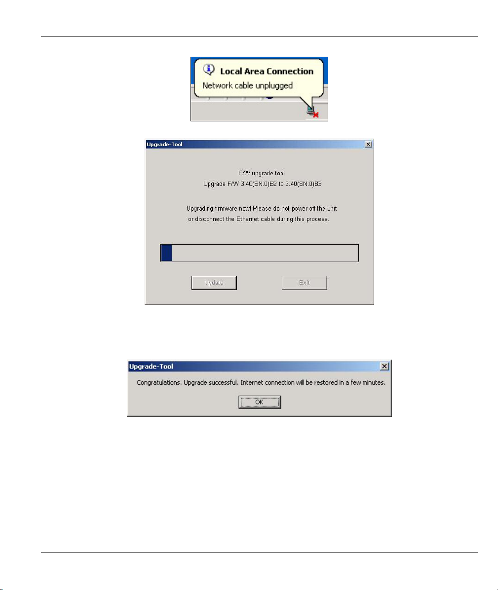
Prestige 650M-6x User’s Guide
Step 6. Firmware upload is in progress; do not turn off the Prestige or disconnect the Ethernet cable.
Step 7. The Prestige automatically restarts again.
Step 8. The upload was successful. When you see the next screen, click OK. Wait few minutes before
logging in again and check your new firmware version by using the sys version command
(refer to the Checking System Firmware Version section).
Firmware Upload 9-3
Page 78

Page 79

Appendices and Index
Part III:
APPENDICES AND INDEX
This part contains troubleshooting, additional background information and an index of key terms.
III
Page 80

Page 81

Prestige 650M-6x User’s Guide
Appendix A
Troubleshooting
This chapter covers potential problems and the corresponding remedies.
Make sure you have securely attached the proper cables to the proper ports. Refer to Rear Panel section for
this information. If your Prestige still does not work properly, refer to the table shown next.
PROBLEM CORRECTIVE ACTION
No LEDs are on when I
turn the Prestige on.
The LAN LED(s) is off. Verify that the attached device(s) is turned on and properly connected.
The VDSL LED is not on or
is blinking.
Your Prestige or power adaptor may have malfunctioned. Check that the
power cable is connected properly and that you are using the supplied
power adaptor for your region. Make sure the power source is turned on and
that the Prestige is receiving sufficient power. Try a different power outlet. If
all this fails, contact your vendor.
Make sure the Ethernet cards are working on the attached devices.
Verify that the proper network cable type is used and its length does not
exceed 100 meters. Use unshielded twisted pair (UTP) or shielded twistedpair (STP) Ethernet cables for the Ethernet ports. For 10 Base-T
connections, use 100W 2-pair UTP/STP Category 3, 4 or 5 cable(s). For
100 Base-TX connections, use 100W 2-pair UTP/STP Category 5 cable(s).
Make sure the distance from the Prestige to the DSLAM does not exceed
1.25km (3750feet). Rates deteriorate the further away the DSLAM is from
the modem. Check with your telephone company that the telephone line
quality is good enough for VDSL transmission.
If G.hs is disabled in the Prestige, then make sure the Prestige and the
remote DSLAM have the same VDSL parameters. Use the CI commands
(refer to the chapter on VDSL commands) to check your VDSL parameters
such as band plan, band modifier, channel type (is interleave delay set?),
encapsulation mode, VPI/VCI numbers, QoS parameters and service
categories.
When G.hs is enabled in the Prestige, the DSLAM dictates (and overrides)
all modem VDSL parameters.
Troubleshooting A-1
Page 82

Page 83

Prestige 650M-6x User’s Guide
Appendix B
Virtual Circuit Topology
ATM is a connection-oriented technology, meaning that it sets up virtual circuits over which end systems
communicate. The terminology for virtual circuits is as follows:
• Virtual Channel Logical connections between ATM switches
• Virtual Path A bundle of virtual channels
• Virtual Circuit A series of virtual paths between circuit end points
Diagram B-1 Virtual Circuit Topology
Think of a virtual path as a cable that contains a bundle of wires. The cable connects two points and wires
within the cable provide individual circuits between the two points. In an ATM cell header, a VPI (Virtual
Path Identifier) identifies a link formed by a virtual path; a VCI (Virtual Channel Identifier) identifies a
channel within a virtual path.
The VPI and VCI identify a virtual path, that is, termination points between ATM switches. A series of
virtual paths make up a virtual circuit.
Your service provider should supply you with VPI/VCI numbers.
Virtual Circuit Topology B-1
Page 84

Page 85

Prestige 650M-6x User’s Guide
Appendix C
IP Subnetting
IP Addressing
Routers “route” based on the network number. The router that delivers the data packet to the correct
destination host uses the host ID.
IP Classes
An IP address is made up of four octets (eight bits), written in dotted decimal notation, for example,
192.168.1.1. IP addresses are categorized into different classes. The class of an address depends on the value
of its first octet.
Class “A” addresses have a 0 in the left most bit. In a class “A” address the first octet is the network
number and the remaining three octets make up the host ID.
Class “B” addresses have a 1 in the left most bit and a 0 in the next left most bit. In a class “B” address
the first two octets make up the network number and the two remaining octets make up the host ID.
Class “C” addresses begin (starting from the left) with 1 1 0. In a class “C” address the first three octets
make up the network number and the last octet is the host ID.
Class “D” addresses begin with 1 1 1 0. Class “D” addresses are used for multicasting. (There is also a
class “E” address. It is reserved for future use.)
Chart C-1 Classes of IP Addresses
IP ADDRESS: OCTET 1 OCTET 2 OCTET 3 OCTET 4
Class A 0 Network number Host ID Host ID Host ID
Class B 10 Network number Network number Host ID Host ID
Class C 110 Network number Network number Network number Host ID
Host IDs of all zeros or all ones are not allowed.
Therefore:
A class “C” network (8 host bits) can have 2
A class “B” address (16 host bits) can have 2
IP Subnetting C-1
8
–2 or 254 hosts.
16
–2 or 65534 hosts.
Page 86

Prestige 650M-6x User’s Guide
A class “A” address (24 host bits) can have 224 –2 hosts (approximately 16 million hosts).
Since the first octet of a class “A” IP address must contain a “0”, the first octet of a class “A” address can
have a value of 0 to 127.
Similarly the first octet of a class “B” must begin with “10”, therefore the first octet of a class “B” address
has a valid range of 128 to 191. The first octet of a class “C” address begins with “110”, and therefore has a
range of 192 to 223.
Chart C-2 Allowed IP Address Range By Class
CLASS ALLOWED RANGE OF FIRST OCTET
(BINARY)
Class A
Class B
Class C
Class D
00000000 to 01111111
10000000 to 10111111
11000000 to 11011111
11100000 to 11101111
ALLOWED RANGE OF FIRST OCTET
(DECIMAL)
0 to 127
128 to 191
192 to 223
224 to 239
Subnet Masks
A subnet mask is used to determine which bits are part of the network number, and which bits are part of the
host ID (using a logical AND operation). A subnet mask has 32 bits; each bit of the mask corresponds to a bit
of the IP address. If a bit in the subnet mask is a “1” then the corresponding bit in the IP address is part of the
network number. If a bit in the subnet mask is “0” then the corresponding bit in the IP address is part of the
host ID.
Subnet masks are expressed in dotted decimal notation just as IP addresses are. The “natural” masks for class
A, B and C IP addresses are as follows.
Chart C-3 “Natural” Masks
CLASS NATURAL MASK
A 255.0.0.0
B 255.255.0.0
C 255.255.255.0
Subnetting
With subnetting, the class arrangement of an IP address is ignored. For example, a class C address no longer
has to have 24 bits of network number and 8 bits of host ID. With subnetting, some of the host ID bits are
converted into network number bits. By convention, subnet masks always consist of a continuous sequence
C-2 IP Subnetting
Page 87

Prestige 650M-6x User’s Guide
of ones beginning from the left most bit of the mask, followed by a continuous sequence of zeros, for a total
number of 32 bits.
Since the mask is always a continuous number of ones beginning from the left, followed by a continuous
number of zeros for the remainder of the 32 bit mask, you can simply specify the number of ones instead of
writing the value of each octet. This is usually specified by writing a “/” followed by the number of bits in
the mask after the address.
For example, 192.1.1.0 /25 is equivalent to saying 192.1.1.0 with mask 255.255.255.128.
The following table shows all possible subnet masks for a class “C” address using both notations.
Chart C-4 Alternative Subnet Mask Notation
SUBNET MASK IP ADDRESS SUBNET MASK “1” BITS LAST OCTET BIT VALUE
255.255.255.0 /24 0000 0000
255.255.255.128 /25 1000 0000
255.255.255.192 /26 1100 0000
255.255.255.224 /27 1110 0000
255.255.255.240 /28 1111 0000
255.255.255.248 /29 1111 1000
255.255.255.252 /30 1111 1100
The first mask shown is the class “C” natural mask. Normally if no mask is specified it is understood that the
natural mask is being used.
Example: Two Subnets
As an example, you have a class “C” address 192.168.1.0 with subnet mask of 255.255.255.0.
NETWORK NUMBER HOST ID
IP Address 192.168.1. 0
IP Address (Binary) 11000000.10101000.00000001. 00000000
Subnet Mask 255.255.255. 0
Subnet Mask (Binary) 11111111.11111111.11111111. 00000000
The first three octets of the address make up the network number (class “C”). You want to have two separate
networks.
IP Subnetting C-3
Page 88

Prestige 650M-6x User’s Guide
Divide the network 192.168.1.0 into two separate subnets by converting one of the host ID bits of the IP
address to a network number bit. The “borrowed” host ID bit can be either “0” or “1” thus giving two
subnets; 192.168.1.0 with mask 255.255.255.128 and 192.168.1.128 with mask 255.255.255.128.
In the following charts, shaded/bolded last octet bit values indicate host ID bits
“borrowed” to form network ID bits. The number of “borrowed” host ID bits
determines the number of subnets you can have. The remaining number of host ID
bits (after “borrowing”) determines the number of hosts you can have on each
subnet.
Chart C-5 Subnet 1
NETWORK NUMBER LAST OCTET BIT VALUE
IP Address 192.168.1. 0
IP Address (Binary) 11000000.10101000.00000001.
Subnet Mask 255.255.255. 128
Subnet Mask (Binary) 11111111.11111111.11111111.
Subnet Address: 192.168.1.0 Lowest Host ID: 192.168.1.1
Broadcast Address: 192.168.1.127 Highest Host ID: 192.168.1.126
00000000
10000000
Chart C-6 Subnet 2
NETWORK NUMBER LAST OCTET BIT VALUE
IP Address 192.168.1. 128
IP Address (Binary) 11000000.10101000.00000001.
Subnet Mask 255.255.255. 128
Subnet Mask (Binary) 11111111.11111111.11111111.
Subnet Address: 192.168.1.128 Lowest Host ID: 192.168.1.129
Broadcast Address: 192.168.1.255 Highest Host ID: 192.168.1.254
10000000
10000000
The remaining 7 bits determine the number of hosts each subnet can have. Host IDs of all zeros represent the
subnet itself and host IDs of all ones are the broadcast address for that subnet, so the actual number of hosts
available on each subnet in the example above is 2
7
– 2 or 126 hosts for each subnet.
192.168.1.0 with mask 255.255.255.128 is the subnet itself, and 192.168.1.127 with mask 255.255.255.128 is
the directed broadcast address for the first subnet. Therefore, the lowest IP address that can be assigned to an
C-4 IP Subnetting
Page 89

Prestige 650M-6x User’s Guide
actual host for the first subnet is 192.168.1.1 and the highest is 192.168.1.126. Similarly the host ID range for
the second subnet is 192.168.1.129 to 192.168.1.254.
Example: Four Subnets
The above example illustrated using a 25-bit subnet mask to divide a class “C” address space into two
subnets. Similarly to divide a class “C” address into four subnets, you need to “borrow” two host ID bits to
give four possible combinations of 00, 01, 10 and 11. The subnet mask is 26 bits
(11111111.11111111.11111111.11000000) or 255.255.255.192. Each subnet contains 6 host ID bits, giving
6
2
-2 or 62 hosts for each subnet (all 0’s is the subnet itself, all 1’s is the broadcast address on the subnet).
Chart C-7 Subnet 1
NETWORK NUMBER LAST OCTET BIT VALUE
IP Address 192.168.1. 0
IP Address (Binary) 11000000.10101000.00000001.
Subnet Mask (Binary) 11111111.11111111.11111111.
Subnet Address: 192.168.1.0 Lowest Host ID: 192.168.1.1
Broadcast Address: 192.168.1.63 Highest Host ID: 192.168.1.62
00000000
11000000
Chart C-8 Subnet 2
NETWORK NUMBER LAST OCTET BIT VALUE
IP Address 192.168.1. 64
IP Address (Binary) 11000000.10101000.00000001.
Subnet Mask (Binary) 11111111.11111111.11111111.
Subnet Address: 192.168.1.64 Lowest Host ID: 192.168.1.65
Broadcast Address: 192.168.1.127 Highest Host ID: 192.168.1.126
01000000
11000000
Chart C-9 Subnet 3
NETWORK NUMBER LAST OCTET BIT VALUE
IP Address 192.168.1. 128
IP Address (Binary) 11000000.10101000.00000001.
Subnet Mask (Binary) 11111111.11111111.11111111.
Subnet Address: 192.168.1.128 Lowest Host ID: 192.168.1.129
Broadcast Address: 192.168.1.191 Highest Host ID: 192.168.1.190
10000000
11000000
IP Subnetting C-5
Page 90

Prestige 650M-6x User’s Guide
Chart C-10 Subnet 4
NETWORK NUMBER LAST OCTET BIT VALUE
IP Address 192.168.1. 192
IP Address (Binary) 11000000.10101000.00000001.
Subnet Mask (Binary) 11111111.11111111.11111111.
Subnet Address: 192.168.1.192 Lowest Host ID: 192.168.1.193
Broadcast Address: 192.168.1.255 Highest Host ID: 192.168.1.254
11000000
11000000
Example Eight Subnets
Similarly use a 27-bit mask to create 8 subnets (001, 010, 011, 100, 101, 110).
The following table shows class C IP address last octet values for each subnet.
Chart C-11 Eight Subnets
SUBNET SUBNET ADDRESS FIRST ADDRESS LAST ADDRESS BROADCAST ADDRESS
1 0 1 30 31
2 32 33 62 63
3 64 65 94 95
4 96 97 126 127
5 128 129 158 159
6 160 161 190 191
7 192 193 222 223
8 224 223 254 255
The following table is a summary for class “C” subnet planning.
C-6 IP Subnetting
Page 91

Prestige 650M-6x User’s Guide
Chart C-12 Class C Subnet Planning
NO. “BORROWED” HOST BITS SUBNET MASK NO. SUBNETS NO. HOSTS PER SUBNET
1 255.255.255.128 (/25) 2 126
2 255.255.255.192 (/26) 4 62
3 255.255.255.224 (/27) 8 30
4 255.255.255.240 (/28) 16 14
5 255.255.255.248 (/29) 32 6
6 255.255.255.252 (/30) 64 2
7 255.255.255.254 (/31) 128 1
Subnetting With Class A and Class B Networks.
For class “A” and class “B” addresses the subnet mask also determines which bits are part of the network
number and which are part of the host ID.
A class “B” address has two host ID octets available for subnetting and a class “A” address has three host ID
octets (see Chart C-1) available for subnetting.
The following table is a summary for class “B” subnet planning.
Chart C-13 Class B Subnet Planning
NO. “BORROWED” HOST BITS SUBNET MASK NO. SUBNETS NO. HOSTS PER SUBNET
1 255.255.128.0 (/17) 2 32766
2 255.255.192.0 (/18) 4 16382
3 255.255.224.0 (/19) 8 8190
4 255.255.240.0 (/20) 16 4094
5 255.255.248.0 (/21) 32 2046
6 255.255.252.0 (/22) 64 1022
7 255.255.254.0 (/23) 128 510
8 255.255.255.0 (/24) 256 254
9 255.255.255.128
512 126
IP Subnetting C-7
Page 92

Prestige 650M-6x User’s Guide
Chart C-13 Class B Subnet Planning
NO. “BORROWED” HOST BITS SUBNET MASK NO. SUBNETS NO. HOSTS PER SUBNET
(/25)
10 255.255.255.192
(/26)
11 255.255.255.224
(/27)
12 255.255.255.240
(/28)
13 255.255.255.248
(/29)
14 255.255.255.252
(/30)
15 255.255.255.254
(/31)
1024 62
2048 30
4096 14
8192 6
16384 2
32768 1
C-8 IP Subnetting
Page 93
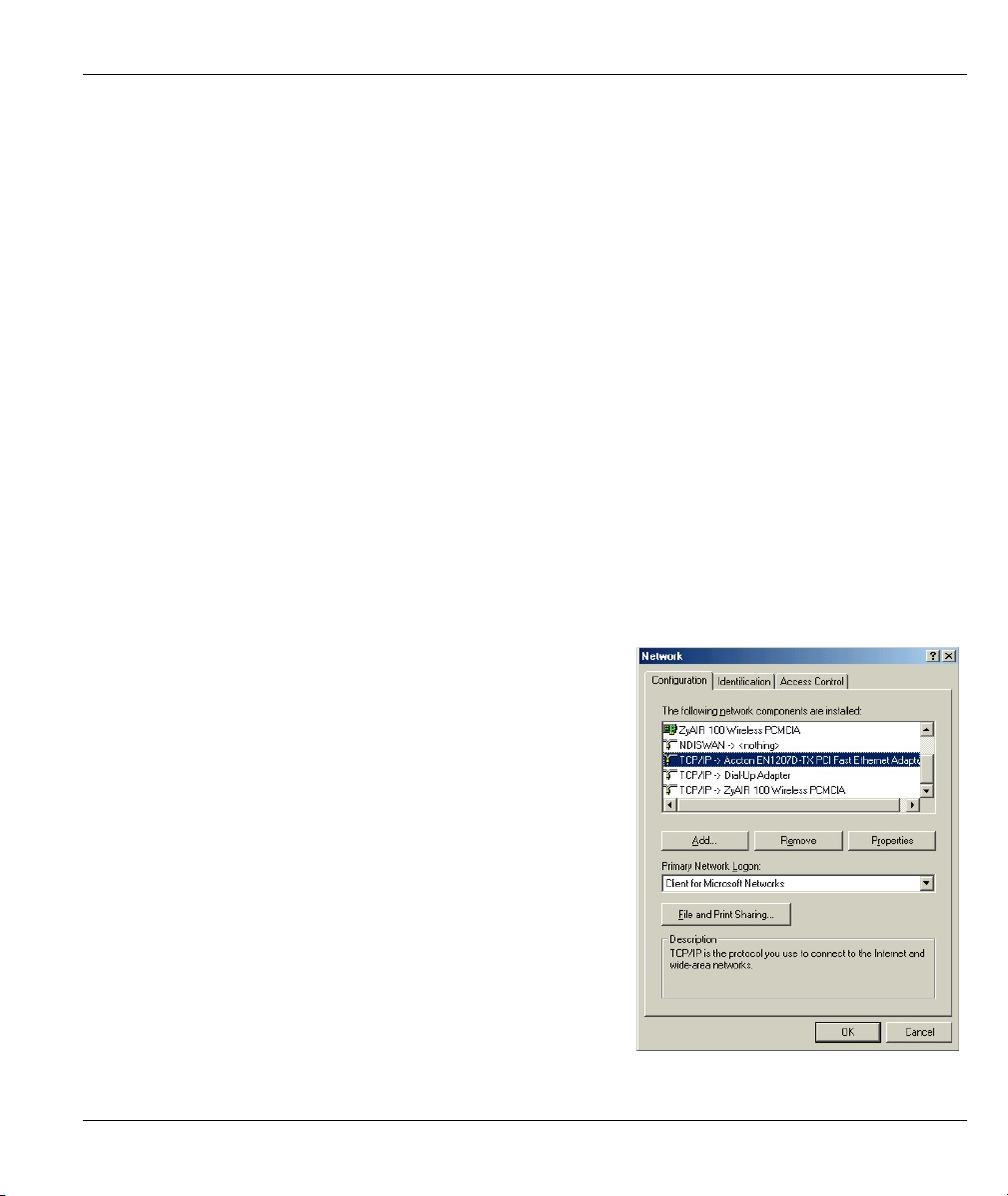
Prestige 650M-6x User’s Guide
Appendix D
Setting up Your Computer’s IP Address
All computers must have a 10M or 100M Ethernet adapter card and TCP/IP installed.
Windows 95/98/Me/NT/2000/XP, Macintosh OS 7 and later operating systems and all versions of
UNIX/LINUX include the software components you need to install and use TCP/IP on your computer.
Windows 3.1 requires the purchase of a third-party TCP/IP application package.
TCP/IP should already be installed on computers using Windows NT/2000/XP, Macintosh OS 7 and later
operating systems.
After the appropriate TCP/IP components are installed, configure the TCP/IP settings in order to
"communicate" with your network.
If you manually assign IP information instead of using dynamic assignment, make sure that your computers
have IP addresses that place them in the same subnet as the Prestige's LAN port.
Windows 95/98/Me
Click Start, Settings, Control Panel and double-click the
Network icon to open the Network window.
Setting up Your Computer’s IP Address D-1
Page 94

Prestige 650M-6x User’s Guide
Installing Components
The Network window Configuration tab displays a list of installed components. You need a network
adapter, the TCP/IP protocol and Client for Microsoft Networks.
If you need the adapter:
In the Network window, click Add.
a.
Select Adapter and then click Add.
b.
Select the manufacturer and model of your network adapter and then click OK.
c.
If you need TCP/IP:
In the Network window, click Add.
a.
Select Protocol and then click Add.
b.
Select Microsoft from the list of manufacturers.
c.
Select TCP/IP from the list of network protocols and then click OK.
d.
If you need Client for Microsoft Networks:
Click Add.
a.
Select Client and then click Add.
b.
Select Microsoft from the list of manufacturers.
c.
Select Client for Microsoft Networks from the list of network clients and then click OK.
d.
e. Restart your computer so the changes you made take effect.
Configuring
In the Network window Configuration tab, select your network adapter's TCP/IP entry and click
1.
Properties.
D-2 Setting up Your Computer’s IP Address
Page 95
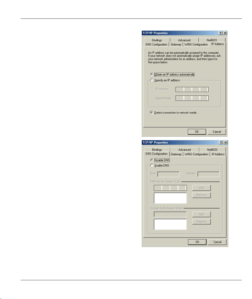
Click the IP Address tab.
2.
-If your IP address is dynamic, select Obtain an
IP address automatically.
-If you have a static IP address, select Specify
an IP address and type your information into
the IP Address and Subnet Mask fields.
Click the DNS Configuration tab.
3.
-If you do not know your DNS information, select
Disable DNS.
-If you know your DNS information, select
Enable DNS and type the information in the
fields below (you may not need to fill them all
in).
Prestige 650M-6x User’s Guide
Setting up Your Computer’s IP Address D-3
Page 96
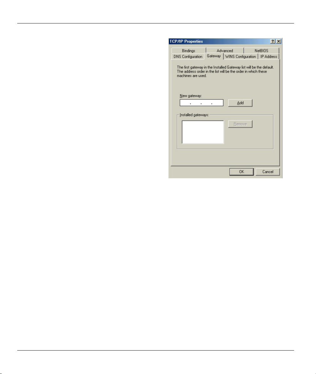
Prestige 650M-6x User’s Guide
Click the Gateway tab.
4.
-If you do not know your gateway’s IP address,
remove previously installed gateways.
-If you have a gateway IP address, type it in the
New gateway field and click Add.
Click OK to save and close the TCP/IP Properties window.
5.
Click OK to close the Network window. Insert the Windows CD if prompted.
6.
7. Turn on your Prestige and restart your computer when prompted.
Verifying Settings
Click Start and then Run.
1.
In the Run window, type "winipcfg" and then click OK to open the IP Configuration window.
2.
3. Select your network adapter. You should see your computer's IP address, subnet mask and default
gateway.
D-4 Setting up Your Computer’s IP Address
Page 97

Windows 2000/NT/XP
For Windows XP, click start, Control Panel. In
1.
Windows 2000/NT, click Start, Settings, Control
Panel.
Prestige 650M-6x User’s Guide
For Windows XP, click Network
2.
Connections. For Windows 2000/NT, click
Network and Dial-up Connections.
Right-click Local Area Connection and
3.
then click Properties.
Setting up Your Computer’s IP Address D-5
Page 98
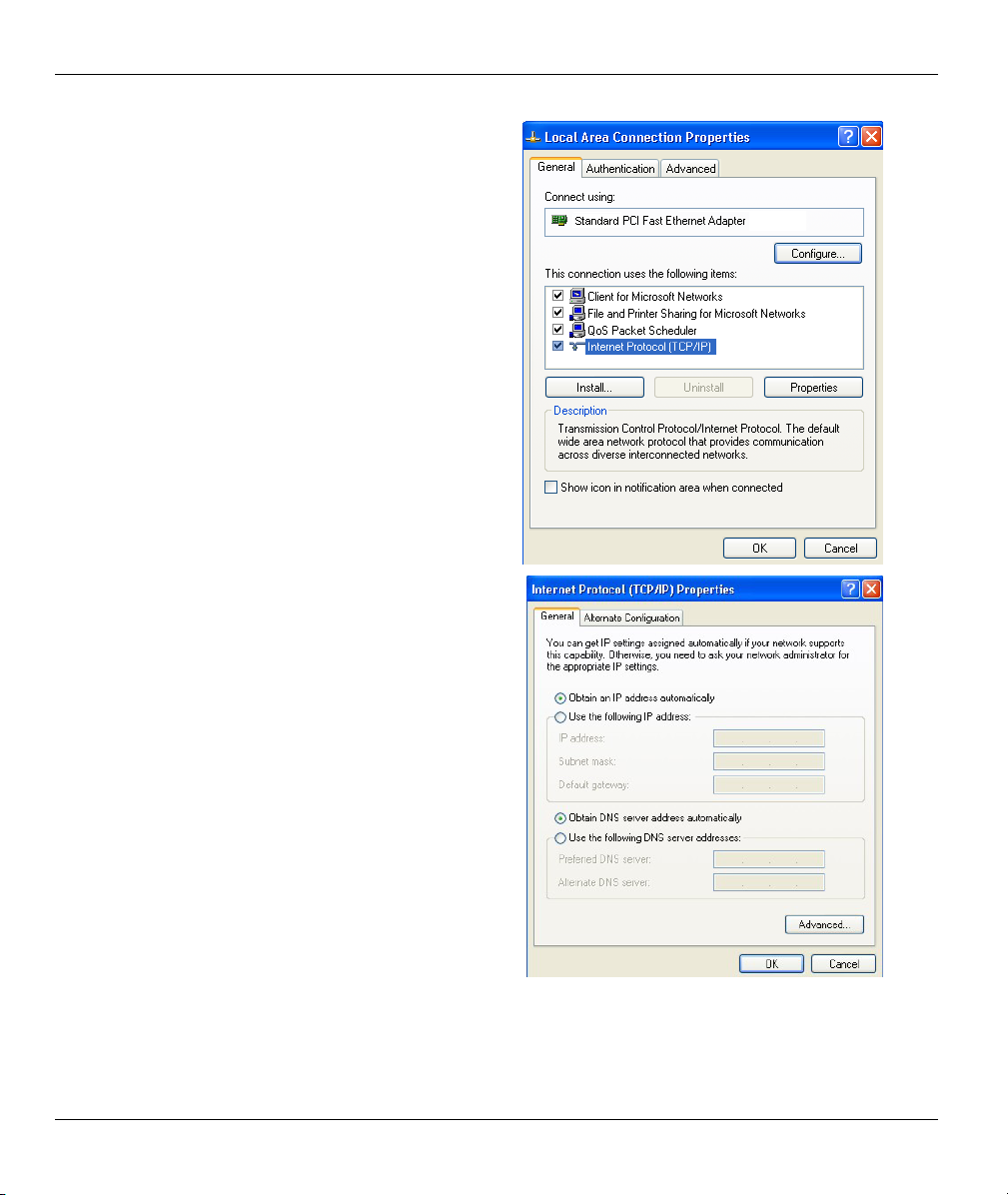
Prestige 650M-6x User’s Guide
Select Internet Protocol (TCP/IP) (under the
4.
General tab in Win XP) and click Properties.
The Internet Protocol TCP/IP Properties
5.
window opens (the General tab in Windows XP).
-If you have a dynamic IP address click Obtain
an IP address automatically.
-If you have a static IP address click Use the
following IP Address and fill in the IP address,
Subnet mask, and Default gateway fields.
Click Advanced.
D-6 Setting up Your Computer’s IP Address
Page 99

6. -If you do not know your gateway's IP address,
remove any previously installed gateways in the
IP Settings tab and click OK.
Do one or more of the following if you want to
configure additional IP addresses:
-In the IP Settings tab, in IP addresses, click
Add.
-In TCP/IP Address, type an IP address in IP
address and a subnet mask in Subnet mask,
and then click Add.
-Repeat the above two steps for each IP address
you want to add.
-Configure additional default gateways in the IP
Settings tab by clicking Add in Default
gateways.
-In TCP/IP Gateway Address, type the IP
address of the default gateway in Gateway. To
manually configure a default metric (the number
of transmission hops), clear the Automatic
metric check box and type a metric in Metric.
-Click Add.
-Repeat the previous three steps for each default gateway you want to add.
-Click OK when finished.
Prestige 650M-6x User’s Guide
Setting up Your Computer’s IP Address D-7
Page 100

Prestige 650M-6x User’s Guide
In the Internet Protocol TCP/IP Properties
7.
window (the General tab in Windows XP):
-Click Obtain DNS server address
automatically if you do not know your DNS
server IP address(es).
-If you know your DNS server IP address(es),
click Use the following DNS server addresses,
and type them in the Preferred DNS server and
Alternate DNS server fields.
If you have previously configured DNS servers,
click Advanced and then the DNS tab to order
them.
Click OK to close the Internet Protocol (TCP/IP) Properties window.
8.
Click OK to close the Local Area Connection Properties window.
9.
10. Turn on your Prestige and restart your computer (if prompted).
Verifying Settings
Click Start, All Programs, Accessories and then Command Prompt.
1.
In the Command Prompt window, type "ipconfig" and then press [ENTER]. You can also open
2.
Network Connections, right-click a network connection, click Status and then click the Support tab.
D-8 Setting up Your Computer’s IP Address
 Loading...