

ZyXEL P-871H User Manual

P-871H Series
VDSL Modem with 4-port Switch
User’s Guide
Version 3.50
7/2005

P-871H Series User’s Guide
Copyright
Copyright © 2005 by ZyXEL Communications Corporation.
The contents of this publication may not be reproduced in any part or as a whole, transcribed, stored in a
retrieval system, translated into any language, or transmitted in any form or by any means, electronic,
mechanical, magnetic, optical, chemical, photocopying, manual, or otherwise, without the prior written
permission of ZyXEL Communications Corporation.
Published by ZyXEL Communications Corporation. All rights reserved.
Disclaimer
ZyXEL does not assume any liability arising out of the application or use of any products, or software
described herein. Neither does it convey any license under its patent rights nor the patent rights of others.
ZyXEL further reserves the right to make changes in any products described herein without notice. This
publication is subject to change without notice.
Copyright 1

P-871H Series User’s Guide
Interference Statements and
Warnings
This device complies with Part 15 of FCC rules. Operation is subject to the following two conditions:
• This device may not cause harmful interference.
• This device must accept any interference received, including interference that may cause undesired
operations.
This equipment has been tested and found to comply with the limits for a Class B digital device pursuant to
Part 15 of the FCC Rules. These limits are designed to provide reasonable protection against harmful
interference in a commercial environment. This equipment generates, uses, and can radiate radio frequency
energy, and if not installed and used in accordance with the instructions, may cause harmful interference to
radio communications.
If this equipment does cause harmful interference to radio/television reception, which can be determined
by turning the equipment off and on, the user is encouraged to try to correct the interference by one or
more of the following measures:
• Reorient or relocate the receiving antenna.
• Increase the separation between the equipment and the receiver.
• Connect the equipment into an outlet on a circuit different from that to which the receiver is
connected.
• Consult the dealer or an experienced radio/TV technician for help.
Notice 1
Changes or modifications not expressly approved by the party responsible for compliance could void the
user's authority to operate the equipment.
Certifications
1 Go to www.zyxel.com
2 Select your product from the drop-down list box on the ZyXEL home page to go
to that product's page.
3 Select the certification you wish to view from this page.
2 Interference Statements and Warnings

P-871H Series User’s Guide
Safety Warnings
For your safety, be sure to read and follow all warning notices and instructions.
• To reduce the risk of fire, use only No. 26 AWG (American Wire Gauge) or larger telecommunication
line cord.
• Do NOT open the device or unit. Opening or removing covers can expose you to dangerous high
voltage points or other risks. ONLY qualified service personnel can service the device. Please contact
your vendor for further information.
• Use ONLY the dedicated power supply for your device. Connect the power cord or power adaptor to
the right supply voltage (110V AC in North America or 230V AC in Europe).
• Do NOT use the device if the power supply is damaged as it might cause electrocution.
• If the power supply is damaged, remove it from the power outlet.
• Do NOT attempt to repair the power supply. Contact your local vendor to order a new power supply.
• Place connecting cables carefully so that no one will step on them or stumble over them. Do NOT
allow anything to rest on the power cord and do NOT locate the product where anyone can walk on
the power cord.
• If you wall mount your device, make sure that no electrical, gas or water pipes will be damaged.
• Do NOT install nor use your device during a thunderstorm. There may be a remote risk of electric
shock from lightning.
• Do NOT expose your device to dampness, dust or corrosive liquids.
• Do NOT use this product near water, for example, in a wet basement or near a swimming pool.
• Make sure to connect the cables to the correct ports.
• Do NOT obstruct the device ventilation slots, as insufficient airflow may harm your device.
• Do NOT store things on the device.
• Connect ONLY suitable accessories to the device.
Safety Warnings 3

P-871H Series User’s Guide
ZyXEL Limited Warranty
ZyXEL warrants to the original end user (purchaser) that this product is free from any defects in materials
or workmanship for a period of up to two years from the date of purchase. During the warranty period, and
upon proof of purchase, should the product have indications of failure due to faulty workmanship and/or
materials, ZyXEL will, at its discretion, repair or replace the defective products or components without
charge for either parts or labor, and to whatever extent it shall deem necessary to restore the product or
components to proper operating condition. Any replacement will consist of a new or re-manufactured
functionally equivalent product of equal value, and will be solely at the discretion of ZyXEL. This
warranty shall not apply if the product is modified, misused, tampered with, damaged by an act of God, or
subjected to abnormal working conditions.
Note
Repair or replacement, as provided under this warranty, is the exclusive remedy of the purchaser. This
warranty is in lieu of all other warranties, express or implied, including any implied warranty of
merchantability or fitness for a particular use or purpose. ZyXEL shall in no event be held liable for
indirect or consequential damages of any kind of character to the purchaser.
To obtain the services of this warranty, contact ZyXEL's Service Center for your Return Material
Authorization number (RMA). Products must be returned Postage Prepaid. It is recommended that the unit
be insured when shipped. Any returned products without proof of purchase or those with an out-dated
warranty will be repaired or replaced (at the discretion of ZyXEL) and the customer will be billed for parts
and labor. All repaired or replaced products will be shipped by ZyXEL to the corresponding return address,
Postage Paid. This warranty gives you specific legal rights, and you may also have other rights that vary
from country to country.
4 ZyXEL Limited Warranty

P-871H Series User’s Guide
Customer Support
Please have the following information ready when you contact customer support.
• Product model and serial number.
• Warranty Information.
• Date that you received your device.
• Brief description of the problem and the steps you took to solve it.
METHOD
LOCATION
CORPORATE
HEADQUARTERS
(WORLDWIDE)
CZECH REPUBLIC
DENMARK
FINLAND
FRANCE
GERMANY
NORTH AMERICA
NORWAY
SPAIN
SWEDEN
SUPPORT E-MAIL TELEPHONE* WEB SITE
SALES E-MAIL FAX FTP SITE
support@zyxel.com.tw +886-3-578-3942 www.zyxel.com
www.europe.zyxel.com
sales@zyxel.com.tw +886-3-578-2439 ftp.zyxel.com
ftp.europe.zyxel.com
info@cz.zyxel.com +420 241 091 350 www.zyxel.cz ZyXEL Communications
info@cz.zyxel.com +420 241 091 359
support@zyxel.dk +45 39 55 07 00 www.zyxel.dk ZyXEL Communications A/S
sales@zyxel.dk +45 39 55 07 07
support@zyxel.fi +358-9-4780-8411 www.zyxel.fi ZyXEL Communications Oy
sales@zyxel.fi +358-9-4780 8448
i nf o @z y xe l .f r + 33 (0 ) 4 7 2 5 2 9 7 9 7 w ww .z y xe l . fr Z yX E L F r an c e
+33 (0)4 72 52 19 20
support@zyxel.de +49-2405-6909-0 www.zyxel.de ZyXEL Deutschland GmbH.
sales@zyxel.de +49-2405-6909-99
support@zyxel.com +1-800-255-4101
+1-714-632-0882
sales@zyxel.com +1-714-632-0858 ftp.us.zyxel.com
support@zyxel.no +47 22 80 61 80 www.zyxel.no ZyXEL Communications A/S
sales@zyxel.no +47 22 80 61 81
support@zyxel.es +34 902 195 420 www.zyxel.es ZyXEL Communications
sales@zyxel.es +34 913 005 345
support@zyxel.se +46 31 744 7700 www.zyxel.se ZyXEL Communications A/S
sales@zyxel.se +46 31 744 7701
www.us.zyxel.com ZyXEL Communications Inc.
REGULAR MAIL
ZyXEL Communications Corp.
6 Innovation Road II
Sc ien ce P ar k
Hsinchu 300
Ta iw a n
Czech s.r.o.
Modranská 621
143 01 Praha 4 - Modrany
Ceská Republika
Col um bu sv ej 5
2860 Soeborg
Denmark
Mal mi nk aa ri 10
00700 Helsinki
Finland
1 ru e d e s V er ge r s
Ba t. 1 / C
69760 Limonest
France
Adenauerstr. 20/A2 D-52146
Wuerselen
Germany
1130 N. Miller St.
Anaheim
CA 92806-2001
U.S.A.
Ni ls H ans en s ve i 13
0667 Oslo
Norway
Alejandro Villegas 33
1º, 28043 Madrid
Spain
Sjöporten 4, 41764 Göteborg
Sweden
Customer Support 5

P-871H Series User’s Guide
METHOD
LOCATION
UNITED KINGDOM
SUPPORT E-MAIL TELEPHONE* WEB SITE
SALES E-MAIL FAX FTP SITE
support@zyxel.co.uk +44 (0) 1344 303044
08707 555779 (UK only)
sales@zyxel.co.uk +44 (0) 1344 303034 ftp.zyxel.co.uk
www.zyxel.co.uk ZyXEL Communications UK
* “+” is the (prefix) number you enter to make an international telephone call.
REGULAR MAIL
Ltd.,11 The Courtyard,
Eastern Road, Bracknell,
Berkshire, RG12 2XB,
United Kingdom (UK)
6 Customer Support

P-871H Series User’s Guide
Table of Contents
Copyright .................................................................................................................. 1
Interference Statements and Warnings.................................................................. 2
Safety Warnings....................................................................................................... 3
ZyXEL Limited Warranty ......................................................................................... 4
Customer Support ................................................................................................... 5
Table of Contents ..................................................................................................... 7
List of Figures .........................................................................................................11
List of Tables .......................................................................................................... 13
Preface.................................................................................................................... 15
Chapter 1
Getting to Know Your Prestige ............................................................................. 17
1.1 Introduction ........................................................................................................ 17
1.2 Software Features ............................................................................................. 17
1.3 Hardware Features ............................................................................................ 18
1.4 Internet Access Application .............................................................................. 18
Chapter 2
Hardware Overview................................................................................................ 19
2.1 Hardware Connection ........................................................................................ 19
2.2 Front Panel LEDs ........................................................................................... 19
2.3 Rear Panel ........................................................................................................ 20
2.3.1 VDSL Port ................................................................................................ 20
2.3.2 PHONE Port ............................................................................................. 20
2.3.3 LAN Ports ................................................................................................. 20
2.3.4 Console Port ........................................................................................... 20
2.3.5 POWER Port ........................................................................................... 21
Chapter 3
The Web Configurator ........................................................................................... 23
3.1 Introduction ........................................................................................................ 23
3.2 System Login .................................................................................................. 23
3.3 The Status Screen ......................................................................................... 24
Table of Contents 7

P-871H Series User’s Guide
3.3.1 Change Your Password ........................................................................ 26
3.4 Prestige Lockout .............................................................................................. 26
3.5 Resetting the Prestige .................................................................................... 27
3.5.1 Reload the Configuration File ................................................................. 27
3.6 Logging Out of the Web Configurator ............................................................... 28
3.7 Help ................................................................................................................. 28
Chapter 4
System Status and Port Statistics........................................................................ 29
4.1 Overview ............................................................................................................ 29
4.2 Port Status Summary .................................................................................... 29
4.2.1 Status: VDSL Port Details ................................................................. 30
4.2.2 Status: Port Details ............................................................................ 32
Chapter 5
Basic Setting ......................................................................................................... 35
5.1 Overview ............................................................................................................ 35
5.2 System Information ...................................................................................... 35
5.3 Introduction to VLANs ...................................................................................... 36
5.4 IGMP Snooping ................................................................................................ 37
5.5 Switch Setup Screen .................................................................................... 37
5.6 IP Setup ........................................................................................................ 39
5.7 Port Setup ..................................................................................................... 40
5.8 Login Setup .................................................................................................. 41
Chapter 6
VLAN ....................................................................................................................... 43
6.1 Introduction to IEEE 802.1Q Tagged VLAN .................................................... 43
6.1.1 Forwarding Tagged and Untagged Frames ............................................. 43
6.2 Select the VLAN Type ...................................................................................... 44
6.3 Static VLAN ...................................................................................................... 45
6.3.1 Static VLAN Status ................................................................................ 45
6.3.2 Configure a Static VLAN ................................................................... 46
6.3.3 Configure VLAN Port Settings ............................................................ 48
6.4 Port-based VLAN Setup ............................................................................. 48
6.4.1 Configure a Port-based VLAN .................................................................. 49
Chapter 7
Broadcast Storm Control ...................................................................................... 51
7.1 Broadcast Storm Control Overview ................................................................ 51
7.2 Broadcast Storm Control Setup ......................................................................... 51
8 Table of Contents

P-871H Series User’s Guide
Chapter 8
Maintenance ........................................................................................................... 53
8.1 The Maintenance Screen ................................................................................ 53
8.1.1 VDSL Chip Reset ..................................................................................... 53
8.1.2 Load Factory Defaults ............................................................................. 53
8.1.3 Reboot System ......................................................................................... 54
8.2 Firmware and Configuration Management ....................................................... 54
8.2.1 Filename Conventions ............................................................................ 55
8.2.1.1 Example FTP Commands .............................................................. 55
8.2.2 FTP Command Line Procedure .............................................................. 55
8.2.3 GUI-based FTP Clients ............................................................................ 56
Chapter 9
MAC Table............................................................................................................... 57
9.1 MAC Table Overview ....................................................................................... 57
9.2 Viewing the MAC Table ..................................................................................... 58
Chapter 10
Introduction to CLI................................................................................................. 59
10.1 Overview .......................................................................................................... 59
10.1.1 Accessing the Command Line Interface ............................................... 59
10.2 The Login Screen ........................................................................................... 59
10.2.1 Command Conventions .......................................................................... 60
10.2.2 Command Syntax Conventions .............................................................. 60
10.2.3 Getting Help .......................................................................................... 60
10.3 Command Summary ....................................................................................... 61
Chapter 11
Command Examples.............................................................................................. 63
11.1 Overview .......................................................................................................... 63
11.2 config save ....................................................................................................... 63
11.3 ip igmpsnoop .................................................................................................... 63
11.4 sys password ................................................................................................... 63
11.5 sys sw bmstorm enable ................................................................................... 64
11.6 sys sw mac list ................................................................................................. 64
11.7 Ethernet Port Setup ......................................................................................... 64
11.7.1 sys sw port enable .................................................................................. 65
11.7.2 sys sw port speed ................................................................................... 65
11.7.3 sys sw port status ................................................................................... 65
11.7.4 sys sw qos defpri .................................................................................... 66
11.7.5 sys sw vlan status .................................................................................. 66
11.7.6 sys sw vlan type ..................................................................................... 66
11.7.7 sys sw vlan1q port status ....................................................................... 67
Table of Contents 9

P-871H Series User’s Guide
11.7.8 sys sw vlan1q port defaultVID ................................................................ 67
11.7.9 sys sw vlan1q svlan list .......................................................................... 68
11.7.10 sys sw vlan1q svlan setentry ................................................................ 68
11.7.11 sys sw vlan1q status ............................................................................. 68
Appendix A
Setting up Your Computer’s IP Address ............................................................. 71
Windows 95/98/Me .................................................................................................. 71
Installing Components....................................................................................... 72
Configuring........................................................................................................ 73
Verifying Settings .............................................................................................. 74
Windows 2000/NT/XP ............................................................................................. 74
Verifying Settings .............................................................................................. 79
Macintosh OS 8/9 .................................................................................................... 79
Verifying Settings .............................................................................................. 81
Macintosh OS X....................................................................................................... 81
Verifying Settings .............................................................................................. 82
Linux ........................................................................................................................ 82
Using the K Desktop Environment (KDE) ......................................................... 83
Using Configuration Files .................................................................................. 84
Figure 69 Verifying Settings .............................................................................. 86
Appendix B
IP Subnetting.......................................................................................................... 87
IP Addressing .......................................................................................................... 87
IP Classes ............................................................................................................... 87
Subnet Masks.......................................................................................................... 88
Subnetting ............................................................................................................... 88
Example: Two Subnets............................................................................................ 89
Example: Four Subnets ........................................................................................... 91
Example Eight Subnets ........................................................................................... 92
Subnetting With Class A and Class B Networks. .................................................... 93
Appendix C
ASCII Characters.................................................................................................... 95
ASCII Code.............................................................................................................. 95
Index........................................................................................................................ 97
10 Table of Contents

P-871H Series User’s Guide
List of Figures
Figure 1 Internet Access Application .....................................................................18
Figure 2 Front Panel .............................................................................................. 19
Figure 3 Rear Panel ............................................................................................... 20
Figure 4 Web Configurator: Login .......................................................................... 23
Figure 5 Web Configurator Home Screen (Status) ................................................ 24
Figure 6 Change Password ...................................................................................26
Figure 7 Resetting the Prestige: Via the Console Port .......................................... 28
Figure 8 Web Configurator: Logout Screen ........................................................... 28
Figure 9 Status ...................................................................................................... 29
Figure 10 Status: Port Details (VDSL) .................................................................. 31
Figure 11 Status Port Details (Ethernet) ................................................................32
Figure 12 System Info ........................................................................................... 35
Figure 13 Switch Setup ......................................................................................... 38
Figure 14 IP Setup .................................................................................................39
Figure 15 Port Setup ............................................................................................. 40
Figure 16 Logins ....................................................................................................41
Figure 17 Prestige Setup: Select VLAN Type ........................................................ 45
Figure 18 VLAN: VLAN Status .............................................................................. 46
Figure 19 VLAN: Static VLAN ...............................................................................47
Figure 20 VLAN: VLAN Port Setting ...................................................................... 48
Figure 21 Port Based VLAN Setup (All Connected) .............................................. 49
Figure 22 Port Based VLAN Setup (Port Isolation) ...............................................49
Figure 23 Broadcast Storm Control ....................................................................... 51
Figure 24 Maintenance ......................................................................................... 53
Figure 25 VDSL Chip Reset: Confirmation ............................................................ 53
Figure 26 Load Factory Default: Conformation .....................................................54
Figure 27 Load Factory Default: Start .................................................................... 54
Figure 28 Reboot System: Confirmation ............................................................... 54
Figure 29 MAC Table Flowchart ............................................................................ 58
Figure 30 MAC Table .............................................................................................58
Figure 31 CLI: Login Screen .................................................................................. 59
Figure 32 CLI Help: Sample Output ...................................................................... 60
Figure 33 ip igmpsnoop Command Example ......................................................... 63
Figure 34 sys password Command Example ....................................................... 64
Figure 35 sys sw bmstorm enable Command Example ........................................ 64
Figure 36 sys sw mac list Command Example ...................................................... 64
Figure 37 sys sw port enable Command Example ................................................ 65
Figure 38 sys sw port speed Command Example ................................................. 65
List of Figures 11

P-871H Series User’s Guide
Figure 39 sys sw port status Command Example ................................................. 65
Figure 40 sys sw qos defpri Command Example .................................................. 66
Figure 41 sys sw vlan status Command Example ................................................. 66
Figure 42 sys sw vlan type Command Example .................................................... 67
Figure 43 sys sw vlan1q port status Command Example ...................................... 67
Figure 44 sys sw vlan1q prt defaultVID Command Example ................................67
Figure 45 sys sw vlan1q svlan list Command Example ......................................... 68
Figure 46 sys sw vlan1q svlan setentry Command Example ............................... 68
Figure 47 sys sw vlan1q status Command Example .............................................69
Figure 48 WIndows 95/98/Me: Network: Configuration .......................................... 72
Figure 49 Windows 95/98/Me: TCP/IP Properties: IP Address .............................. 73
Figure 50 Windows 95/98/Me: TCP/IP Properties: DNS Configuration .................. 74
Figure 51 Windows XP: Start Menu ........................................................................ 75
Figure 52 Windows XP: Control Panel ................................................................... 75
Figure 53 Windows XP: Control Panel: Network Connections: Properties .............76
Figure 54 Windows XP: Local Area Connection Properties ...................................76
Figure 55 Windows XP: Internet Protocol (TCP/IP) Properties ..............................77
Figure 56 Windows XP: Advanced TCP/IP Properties ........................................... 78
Figure 57 Windows XP: Internet Protocol (TCP/IP) Properties ..............................79
Figure 58 Macintosh OS 8/9: Apple Menu .............................................................. 80
Figure 59 Macintosh OS 8/9: TCP/IP ..................................................................... 80
Figure 60 Macintosh OS X: Apple Menu ................................................................ 81
Figure 61 Macintosh OS X: Network ...................................................................... 82
Figure 62 Red Hat 9.0: KDE: Network Configuration: Devices .............................83
Figure 63 Red Hat 9.0: KDE: Ethernet Device: General ...................................... 83
Figure 64 Red Hat 9.0: KDE: Network Configuration: DNS ................................... 84
Figure 65 Red Hat 9.0: KDE: Network Configuration: Activate ....................... 84
Figure 66 Red Hat 9.0: Dynamic IP Address Setting in ifconfig-eth0 ...................85
Figure 67 Red Hat 9.0: Static IP Address Setting in ifconfig-eth0 .......................85
Figure 68 Red Hat 9.0: DNS Settings in resolv.conf ............................................ 85
Figure 69 Red Hat 9.0: Restart Ethernet Card ..................................................... 86
Figure 70 Red Hat 9.0: Checking TCP/IP Properties ........................................... 86
12 List of Figures

P-871H Series User’s Guide
List of Tables
Table 1 Front Panel LEDs ...................................................................................... 19
Table 2 Navigation Panel Sub-links Overview ....................................................... 25
Table 3 Web Configurator Screen Sub-links Details .............................................. 25
Table 4 Navigation Panel Links ............................................................................. 25
Table 5 Password .................................................................................................. 26
Table 6 Status ........................................................................................................30
Table 7 Status: VDSL Port Details ......................................................................... 31
Table 8 Status: Port Details ....................................................................................32
Table 9 System Info ............................................................................................... 36
Table 10 Switch Setup ........................................................................................... 38
Table 11 IP Setup ................................................................................................... 39
Table 12 Port Setup ............................................................................................... 40
Table 13 Password ................................................................................................ 41
Table 14 IEEE 802.1q Terminology ....................................................................... 44
Table 15 VLAN: VLAN Status ................................................................................ 46
Table 16 VLAN: Static VLAN ................................................................................. 47
Table 17 VLAN: VLAN Port Setting ....................................................................... 48
Table 18 Port Based VLAN Setup ......................................................................... 50
Table 19 Broadcast Storm Control .........................................................................51
Table 20 Filename Conventions ............................................................................55
Table 21 MAC Table ..............................................................................................58
Table 22 Command Summary ............................................................................... 61
Table 23 Classes of IP Addresses ......................................................................... 87
Table 24 Allowed IP Address Range By Class ...................................................... 88
Table 25 “Natural” Masks ...................................................................................... 88
Table 26 Alternative Subnet Mask Notation ........................................................... 89
Table 27 Two Subnets Example ............................................................................ 89
Table 28 Subnet 1 .................................................................................................. 90
Table 29 Subnet 2 .................................................................................................. 90
Table 30 Subnet 1 .................................................................................................. 91
Table 31 Subnet 2 .................................................................................................. 91
Table 32 Subnet 3 .................................................................................................. 91
Table 33 Subnet 4 .................................................................................................. 92
Table 34 Eight Subnets .......................................................................................... 92
Table 35 Class C Subnet Planning ........................................................................ 92
Table 36 Class B Subnet Planning ........................................................................93
List of Tables 13

P-871H Series User’s Guide
14 List of Tables
P-871H Series User’s Guide
Preface
Congratulations on your purchase of the Prestige 871H Series VDSL Modem with 4-port
switch.
This preface introduces you to the Prestige Ethernet Prestige and discusses the conventions of
this User’s Guide. It also provides information on other related documentation.
Note: Register your product online to receive e-mail notices of firmware
upgrades and information at www.zyxel.com for global products, or at
www.us.zyxel.com for North American products.
About This User's Guide
This manual is designed to guide you through the configuration of your Prestige for its various
applications.
Related Documentation
• Quick Start Guide
The Quick Start Guide is designed to help you get up and running right away. They
contain connection information and instructions on getting started.
• Web Configurator Online Help
Embedded web help for descriptions of individual screens and supplementary
information.
• ZyXEL Glossary and Web Site
Please refer to www.zyxel.com for an online glossary of networking terms and additional
support documentation.
Syntax Conventions
• “Enter” means for you to type one or more characters. “Select” or “Choose” means for
you to use one of the predefined choices.
• Command and arrow keys are enclosed in square brackets.
carriage return key;
• Mouse action sequences are denoted using a comma. For example, “click the Apple icon,
Control Panels and then Modem” means first click the Apple icon, then point your
mouse pointer to Control Panels and then click Modem.
• For brevity’s sake, we will use “e.g.,” as a shorthand for “for instance”, and “i.e.,” for
“that is” or “in other words” throughout this manual.
• The Prestige 871H Series VDSL Modem may be referred to as “the Prestige” or “the
device” in this User’s Guide.
[ESC] means the Escape key and [SPACE BAR] means the Space Bar.
[ENTER] means the Enter, or
Preface 15
P-871H Series User’s Guide
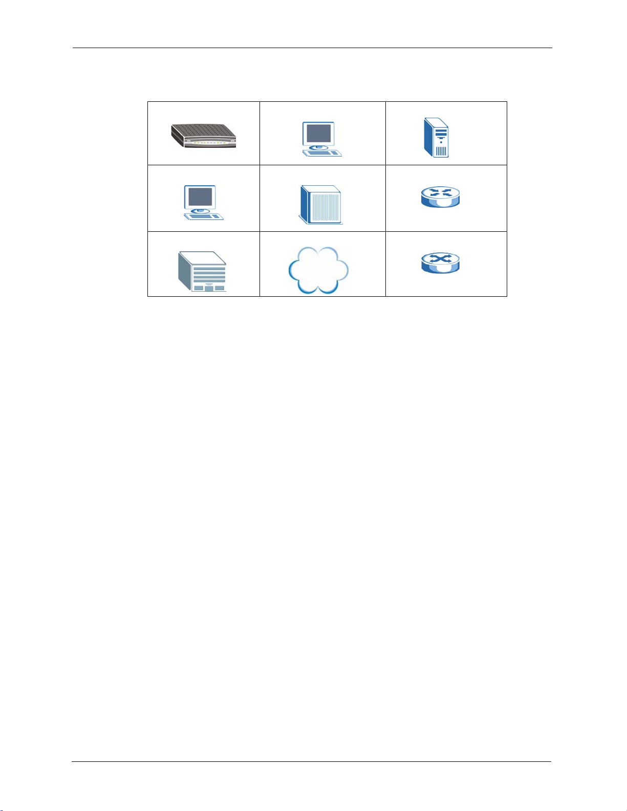
Graphics Icons Key
Prestige Computer Server
Computer DSLAM Gateway
Central Office/ ISP Internet Hub/Prestige
User Guide Feedback
Help us help you. E-mail all User Guide-related comments, questions or suggestions for
improvement to techwriters@zyxel.com.tw or send regular mail to The Technical Writing
Team, ZyXEL Communications Corp., 6 Innovation Road II, Science-Based Industrial Park,
Hsinchu, 300, Taiwan. Thank you.
16 Preface

Getting to Know Your Prestige
This chapter introduces the main features and applications of the Prestige.
1.1 Introduction
The Prestige can be used for high-speed Internet access through a VDSL connection over the
telephone line. Its 10/100M auto-negotiating LAN interface enables fast data transfer of either
10Mbps or 100Mbps in either half-duplex or full-duplex mode depending on your Ethernet
network.
With its built-in web configurator, managing and configuring the Prestige is easy. In addition,
the Prestige can also be managed via Telnet or any terminal emulator program on the console
port.
P-871H Series User’s Guide
CHAPTER 1
1.2 Software Features
This section describes the general layer-2 bridging and switch features of the Prestige.
VLAN
A VLAN (Virtual Local Area Network) allows a physical network to be partitioned into
multiple logical networks. Devices on a logical network belong to one group. A device can
belong to more than one group. With VLAN, a device cannot directly talk to or hear from
devices that are not in the same group(s); the traffic must first go through a router.
IGMP Snooping
The Prestige supports IGMP snooping enabling group multicast traffic to be only forwarded to
ports that are members of that group; thus allowing you to significantly reduce multicast traffic
passing through your Prestige.
Broadcast Storm Control
Broadcast storm control limits the number of broadcast frames that can be stored in the
Prestige buffer or sent out from the Prestige. Broadcast frames that arrive when the buffer is
full are discarded. Enable this feature to reduce broadcast traffic coming into your network.
Chapter 1 Getting to Know Your Prestige 17
P-871H Series User’s Guide
Configuration and Firmware Maintenance
You can backup or restore the Prestige configuration or upgrade the firmware on the
Prestige.
1.3 Hardware Features
This section describes the ports on the Prestige.
Built-in Switch
The 10/100 Mbps auto-negotiating Ethernet ports allow the Prestige to detect the speed of
incoming transmissions and adjust appropriately without manual intervention. It allows data
transfer of either 10 Mbps or 100 Mbps in either half-duplex or full-duplex mode depending
on your Ethernet network. The ports are also auto-crossover (MDI/MDI-X) meaning they
automatically adjust to either a crossover or straight-through Ethernet cable.
High Speed Internet Access
The Prestige supports transmission speeds of up to 100 Mbps downstream and 50 Mbps
upstream. Actual speeds attained depend on ISP DSLAM environment, and how your Prestige
is configured.
Console Port
Use the console port for local management of the Prestige.
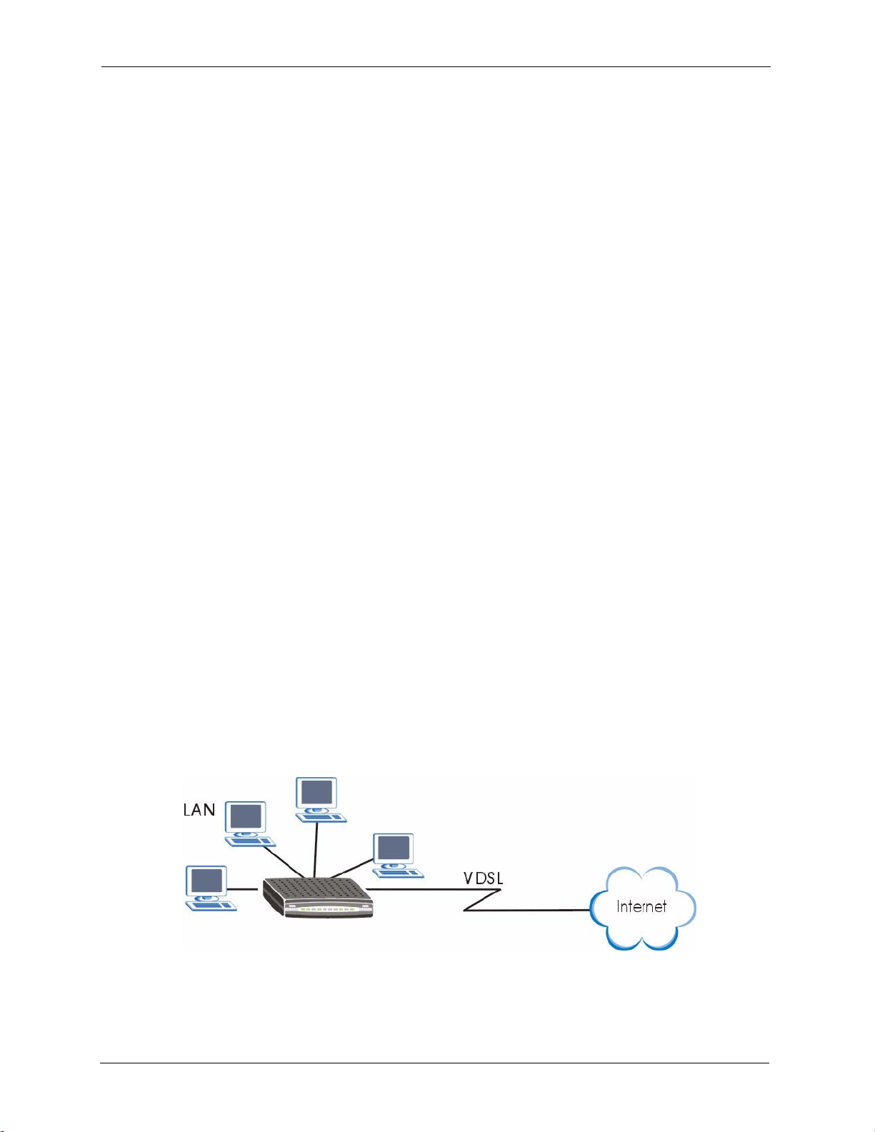
1.4 Internet Access Application
The following figure shows a network example where the Prestige is used for high-speed
Internet access.
Figure 1 Internet Access Application
18 Chapter 1 Getting to Know Your Prestige
This chapter describes the ports and LEDs on the Prestige.
2.1 Hardware Connection
Refer to the Quick Start Guide for information on hardware connections.
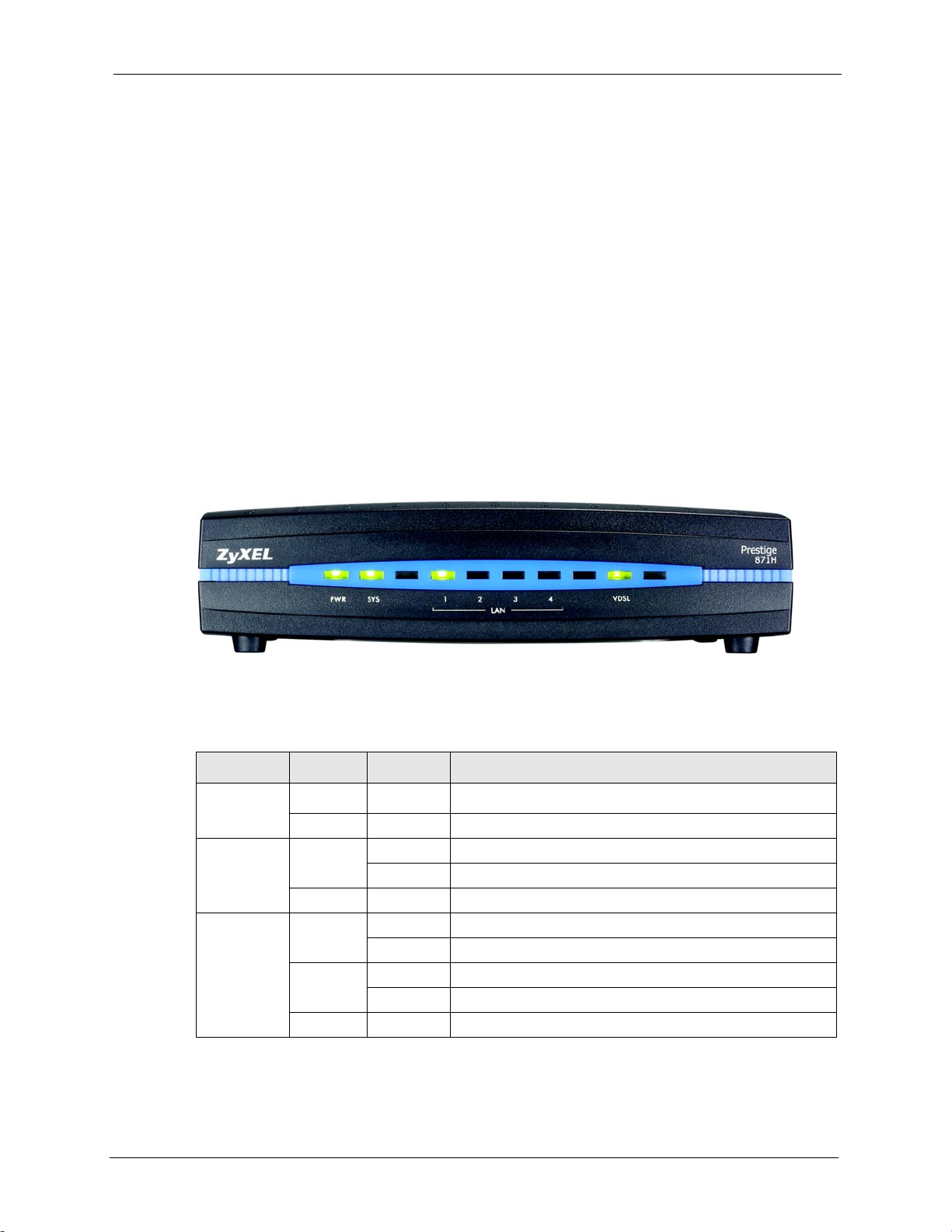
2.2 Front Panel LEDs
Figure 2 Front Panel
P-871H Series User’s Guide
CHAPTER 2
Hardware Overview
The following table describes the LEDs.
Table 1 Front Panel LEDs
LED COLOR STATUS DESCRIPTION
PWR Green On The Prestige is receiving power functioning properly.
Off The Prestige is not receiving power.
SYS Green On The Prestige is functioning properly.
Blinking The Prestige is rebooting.
Off The system is not ready or has malfunctioned.
LAN 1-4 Green On The Prestige has a successful 10Mb Ethernet connection.
Blinking The Prestige is sending/receiving data.
Amber On The Prestige has a successful 100Mb Ethernet connection.
Blinking The Prestige is sending/receiving data.
Off The LAN is not connected.
Chapter 2 Hardware Overview 19
P-871H Series User’s Guide
Table 1 Front Panel LEDs (continued)
LED COLOR STATUS DESCRIPTION
VDSL Green On The Prestige is connected to a DSL line.
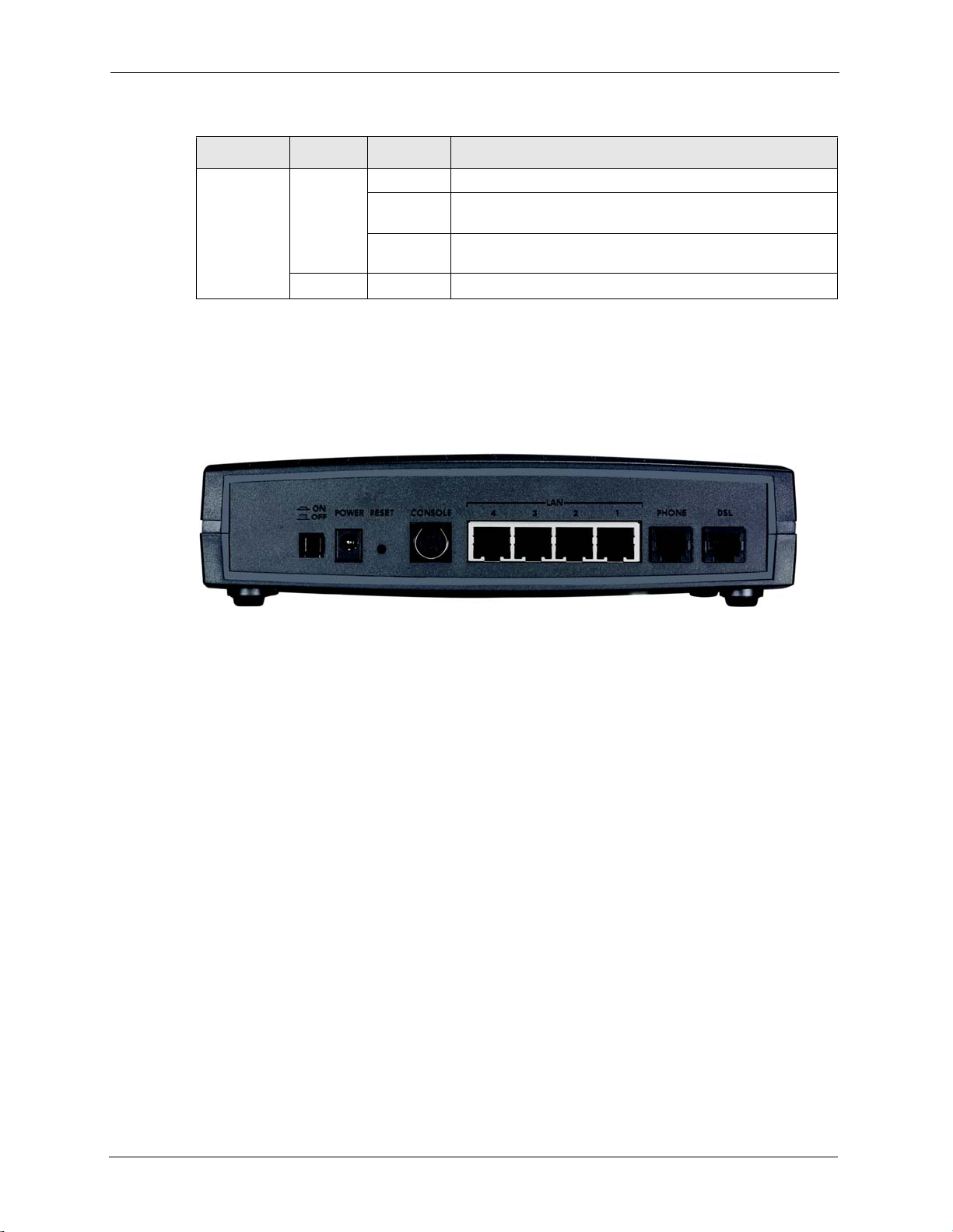
2.3 Rear Panel
The following figure shows the read panel of the Prestige.
Figure 3 Rear Panel
Slow
Blinking
Fast
Blinking
Off The DSL link is down.
The Prestige is initializing the DSL line.
Data is being transmitted or received.
2.3.1 VDSL Port
Connect the Prestige directly to the wall jack using a telephone wire (RJ-11 connector).
2.3.2 PHONE Port
Connect a telephone to this port using a telephone wire (RJ-11 connector).
2.3.3 LAN Ports
The Prestige has four 10/100Mbps auto-negotiating, auto-crossover Ethernet ports. The LAN
interface is auto-crossover, so you may use a crossover cable or a straight-through Ethernet
cable to connect your Prestige to a computer/external hub.
2.3.4 Console Port
You can configure the Prestige via a terminal emulator software on a computer that is
connected to the Prestige through the console port. Connect the one end of the console cable to
the console port of the Prestige and the other end to a serial port (COM1, COM2 or other
COM port) of your computer.
20 Chapter 2 Hardware Overview

2.3.5 POWER Port
Connect the power adaptor to the port labeled POWER on the rear panel of your Prestige.
Push in the power button to turn on the Prestige.
Note: To avoid damage to the Prestige, make sure you use the supplied power
adaptor.
P-871H Series User’s Guide
Chapter 2 Hardware Overview 21

P-871H Series User’s Guide
22 Chapter 2 Hardware Overview
This section introduces the configuration and functions of the web configurator.
3.1 Introduction
The web configurator is an HTML-based management interface that allows easy Prestige
setup and management via Internet browser. Use Internet Explorer 6.0 and later or Netscape
Navigator 7.0 and later versions. The recommended screen resolution is 1024 by 768 pixels.
In order to use the web configurator you need to allow:
• Web browser pop-up windows from your device. Web pop-up blocking is enabled by
default in Windows XP SP (Service Pack) 2.
• JavaScript (enabled by default).
• Java permissions (enabled by default).
P-871H Series User’s Guide
CHAPTER 3
The Web Configurator
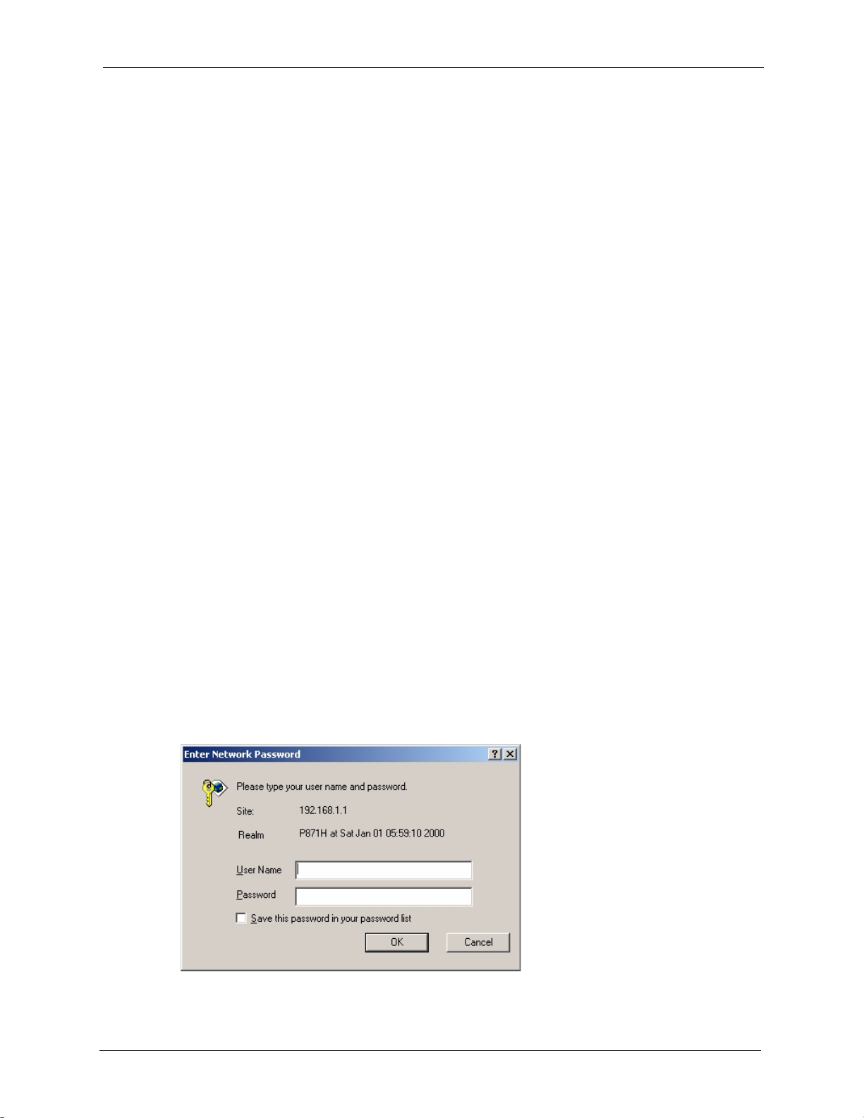
3.2 System Login
1 Start your web browser.
2 Type “http://” and the IP address of the Prestige (for example, the default is 192.168.1.1)
in the Location or Address field. Press
3 The login screen appears. The default username is admin and associated default
password is 1234.
Figure 4 Web Configurator: Login
[ENTER].
4 Click OK to view the first web configurator screen.
Chapter 3 The Web Configurator 23
P-871H Series User’s Guide
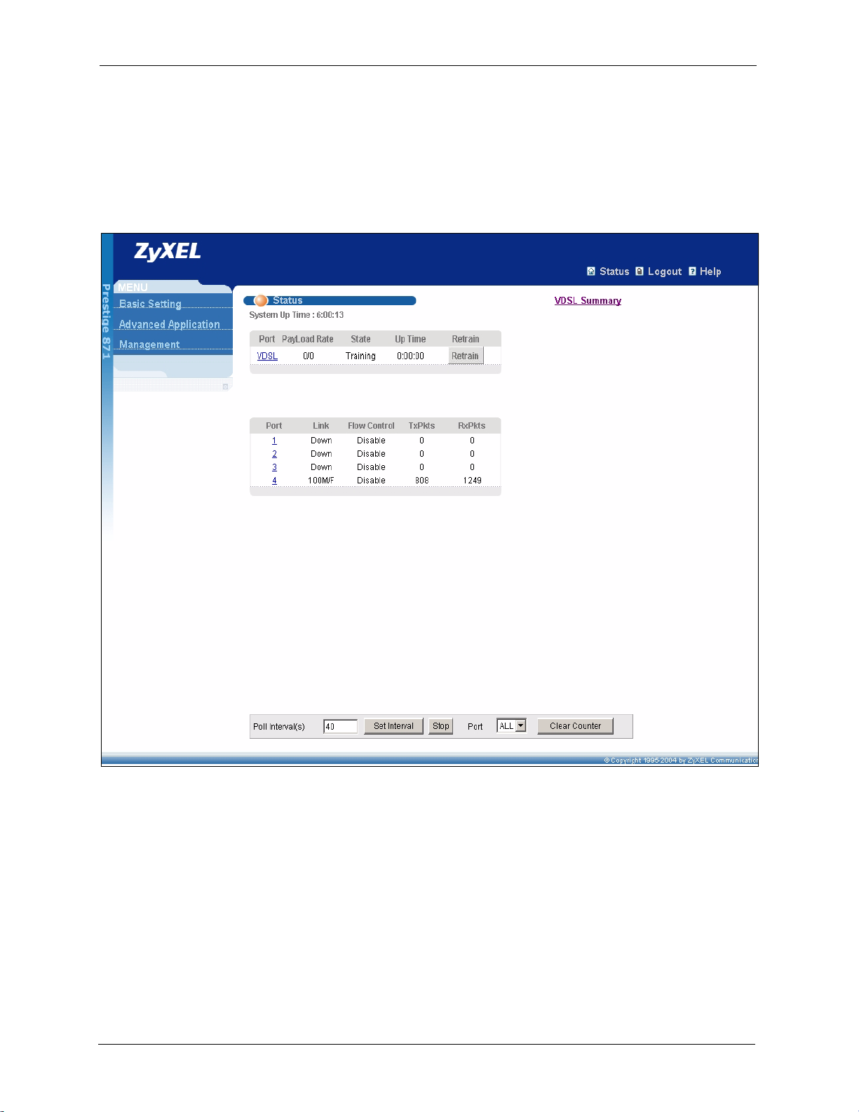
3.3 The Status Screen
The Status screen is the first screen that displays when you access the web configurator.
The following figure shows the navigating components of a web configurator screen.
Figure 5 Web Configurator Home Screen (Status)
In the navigation panel, click a main link to reveal a list of submenu links.
24 Chapter 3 The Web Configurator
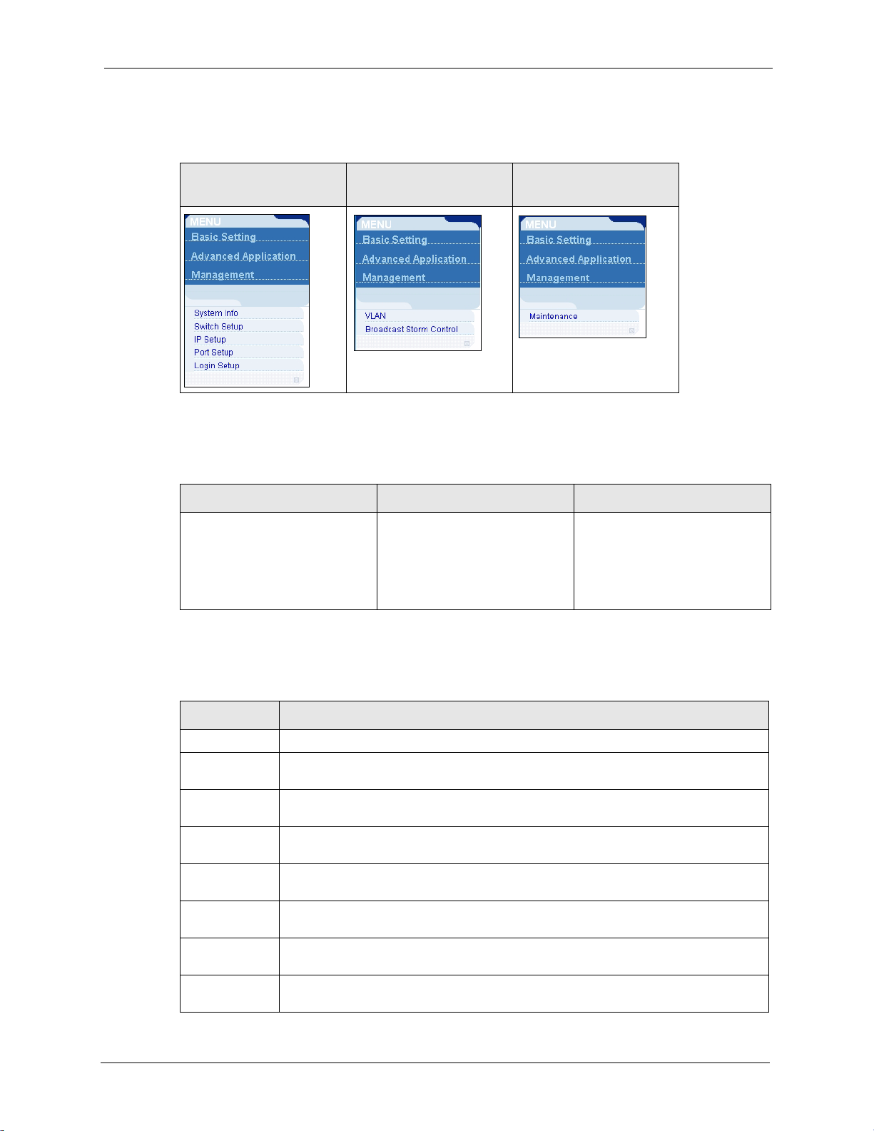
Table 2 Navigation Panel Sub-links Overview
P-871H Series User’s Guide
BASIC SETTING
ADVANCED
APPLICATION
MANAGEMENT
The following table lists the various web configurator screens within the sub-links.
Table 3 Web Configurator Screen Sub-links Details
BASIC SETTING ADVANCED APPLICATION MANAGEMENT
System Info
Switch Setup
IP Setup
Port Setup
VLAN
VLAN Status
VLAN Port Setting
Static VL AN
Broadcast Storm Control
Maintenance
VDSL Chip Reset
Reboot System
The following table describes the links in the navigation panel.
Table 4 Navigation Panel Links
LINK DESCRIPTION
Basic Settings
System Info This link takes you to a screen that displays general system and hardware monitoring
Switch Setup This link takes you to a screen where you can set up global parameters such as
IP Setup This link takes you to a screen where you can configure the IP address, subnet mask
Port Setup This link takes you to screens where you can configure settings for individual
Advanced
Application
VLAN This link takes you to screens where you can configure port-based or 802.1Q VLAN
Broadcast
Storm Control
information.
VLAN type, MAC address learning, IGMP snooping, GARP and priority queues.
(necessary for Prestige management) and default gateway.
Ethernet ports.
(depending on what you configured in the Switch Setup menu).
This link takes you to a screen to set up broadcast filters.
Chapter 3 The Web Configurator 25
P-871H Series User’s Guide
Table 4 Navigation Panel Links (continued)
LINK DESCRIPTION
Management
Maintenance This link takes you to screens where you can perform firmware and configuration file
maintenance as well as reboot the system.
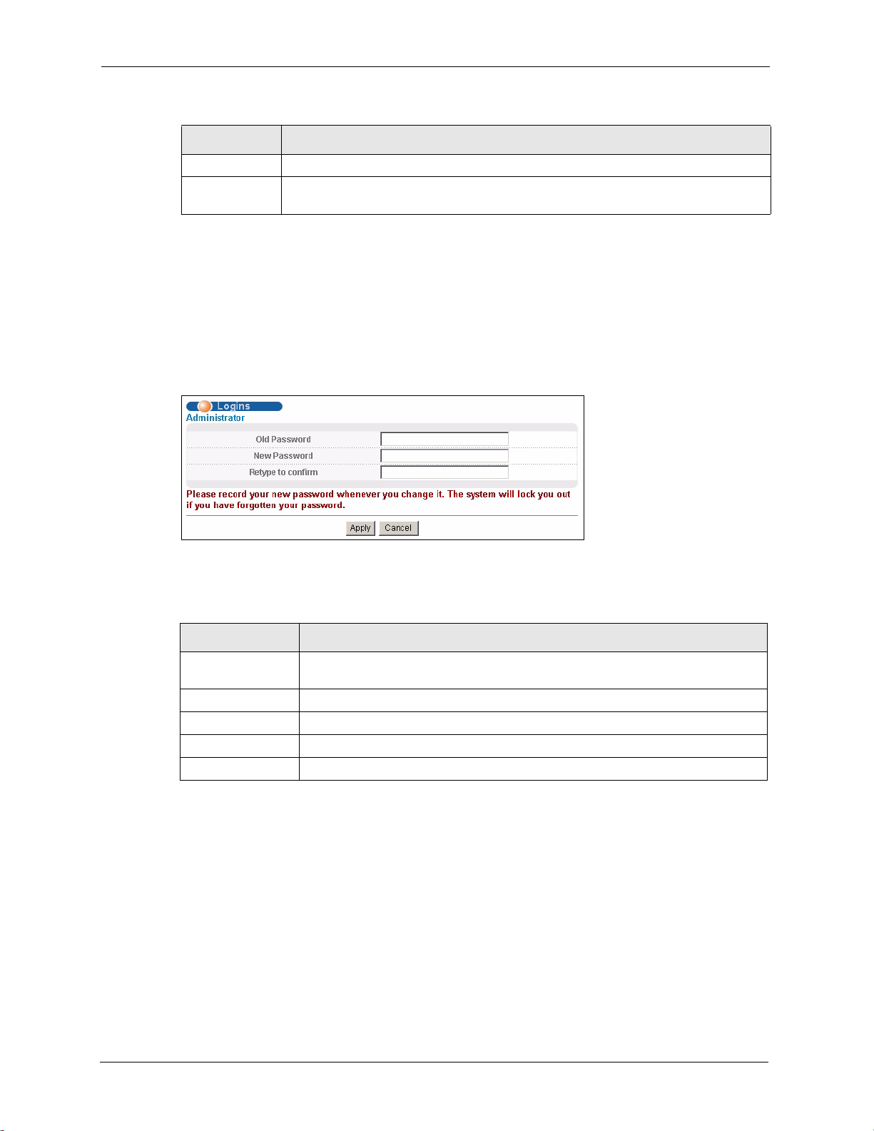
3.3.1 Change Your Password
It is highly recommended that you periodically change the password for accessing the
Prestige. If you didn’t change the default one after you logged in or you want to change to a
new password again, then click Basic Setting, Login Setup to display the screen as shown
next.
Figure 6 Change Password
The following table describes the fields in this screen.
Table 5 Password
LABEL DESCRIPTION
Old Password Type the default password or the existing password you use to access the system
in this field.
New Password Type the new password in this field.
Retype to Confirm Type the new password again in this field.
Apply Click Apply to save your changes back to the Prestige.
Cancel Click Cancel to begin configuring this screen afresh.
3.4 Prestige Lockout
You could lock yourself (and all others) out from the Prestige by:
1 Deleting the management VLAN (default is VLAN 1).
2 Deleting all port-based VLANs with the CPU port as a member. The “CPU port” is the
management port of the Prestige.
3 Disabling all ports.
26 Chapter 3 The Web Configurator

4 Assigning minimum bandwidth to the CPU port. If you limit bandwidth to the CPU port,
you may find that the Prestige performs sluggishly or not at all.
Note: Be careful not to lock yourself and others out of the Prestige.
3.5 Resetting the Prestige
If you lock yourself (and others) from the Prestige or forget the Prestige password, you will
need to reload the factory-default configuration file to reset the Prestige back to the factory
defaults.
3.5.1 Reload the Configuration File
Uploading the factory-default configuration file replaces the current configuration file with the
factory-default configuration file. This means that you will lose all previous configurations
and the speed of the console port will be reset to the default of 9600bps with 8 data bit, no
parity, one stop bit and flow control set to none. The password will also be reset to “1234” and
the IP address to 192.168.1.1.
P-871H Series User’s Guide
To upload the configuration file, do the following:
1 Connect to the console port using a computer with terminal emulation software. See
Section 3.1.1 on page 35 for details.
2 Disconnect and reconnect the Prestige’s power to begin a session. When you reconnect
the Prestige’s power, you will see the initial screen.
3 When you see the message “
seconds ...
4 Type
5 Wait for the “
6 After a configuration file upload, type
atlc after the “Enter Debug Mode” message.
upload on your terminal.
” press any key to enter debug mode.
Starting XMODEM upload” message before activating XMODEM
Press any key to enter Debug Mode within 3
atgo to restart the Prestige.
Chapter 3 The Web Configurator 27
P-871H Series User’s Guide
Figure 7 Resetting the Prestige: Via the Console Port
Bootbase Version: V1.0 | 04/25/2003 10:01:06
RAM: Size = 32768 Kbytes
FLASH: Intel 32M
ZyNOS Version: V3.50(DU.0)b6 | 07/11/2003 18:00:29
Press any key to enter debug mode within 3 seconds.
....................
Enter Debug Mode
ras> atlc
Starting XMODEM upload (CRC mode)....
CCCCCCCCCCCCCCCC
Total 262144 bytes received.
Erasing..
................................................................
ras> atgo
The Prestige is now reinitialized with a default configuration file including the default
password of “1234”.
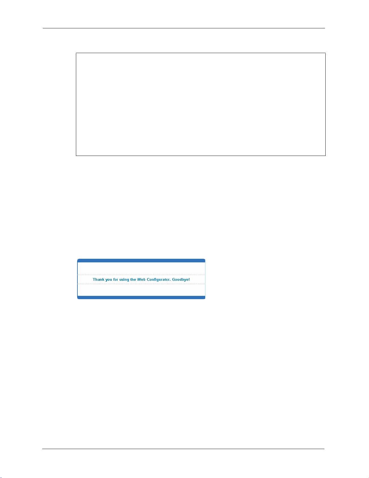
3.6 Logging Out of the Web Configurator
Click Logout in a screen to exit the web configurator. You have to log in with your password
again after you log out. This is recommended after you finish a management session both for
security reasons and so as you don’t lock out other Prestige administrators.
Figure 8 Web Configurator: Logout Screen
3.7 Help
The web configurator’s online help has descriptions of individual screens and some
supplementary information.
Click the Help link from a web configurator screen to view an online help description of that
screen.
28 Chapter 3 The Web Configurator
This chapter describes the system status (web configurator home page) and port details
screens.
4.1 Overview
The home screen of the web configurator displays a port statistical summary table with links to
each port showing statistical details.
P-871H Series User’s Guide
CHAPTER 4
System Status and Port
Statistics
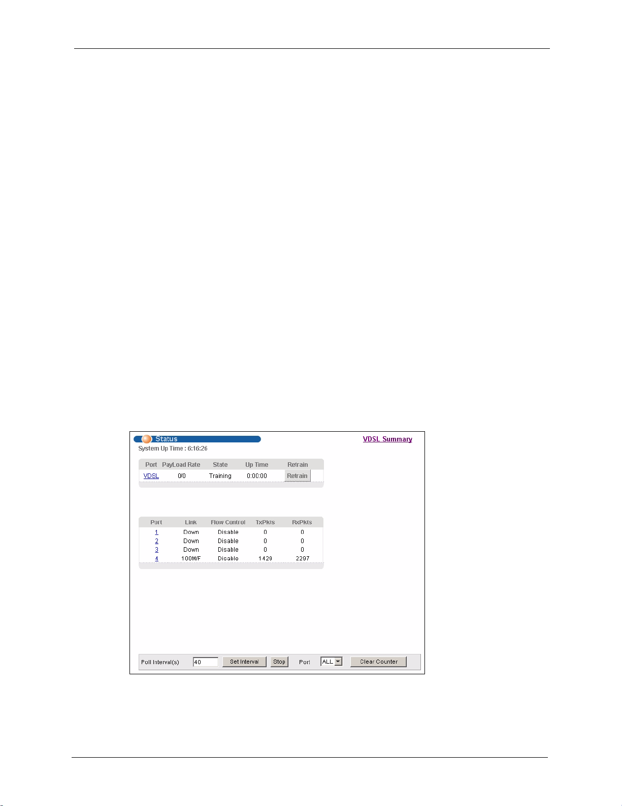
4.2 Port Status Summary
To view the port statistics, click Status in all web configurator screens to display the Status
screen as shown next.
Figure 9 Status
The following table describes the labels in this screen.
Chapter 4 System Status and Port Statistics 29
 Loading...