

Page 1

Quick Start Guide
P-79X Series
G.SHDSL.bis Broadband Gateway
Version 1.00
Edition 1, 03/2016
User’s Guide
Default Login Details
IP Address http://192.168.1.1
User Name admin, user
Password 1234, user
www.zyxel.com
Copyright © 2016 ZyXEL Communications Corporation
Page 2

IMPORTANT!
READ CAREFULLY BEFORE USE.
KEEP THIS GUIDE FOR FUTURE REFERENCE.
Screenshots and graphics in this book may differ slightly from your product due to differences in
your product firmware or your computer operating system. Every effort has been made to ensure
that the information in this manual is accurate.
Related Documentation
•Quick Start Guide
The Quick Start Guide shows how to connect the P-79X and access the Web Con figurator wizards.
It contains information on setting up your network and configuring for Internet access.
•More Information
Go to support.zyxel.com to find other information on the P-79X
.
P-79X Series User’s Guide
2
Page 3

Contents Overview
Contents Overview
User’s Guide .......................................................................................................................................12
Getting To Know Your P-79X ..................................................................................................................13
Introducing the Web Configurator ...........................................................................................................19
Status Screens ........................................................................................................................................25
Internet Setup Wizard ............................................................................................................................. 31
Tutorials ..................................................................................................................................................38
Technical Reference ..........................................................................................................................44
WAN Setup .............................................................................................................................................45
WWAN ....................................................................................................................................................65
LAN Setup ...............................................................................................................................................74
Network Address Translation (NAT) ........................................................................................................87
Firewalls ..................................................................................................................................................99
URL Blocking ........................................................................................................................................ 113
Packet Filter .......................................................................................................................................... 119
VPN .......................................................................................................................................................128
Certificates ............................................................................................................................................150
Static Route ...........................................................................................................................................157
802.1Q ..................................................................................................................................................160
Quality of Service (QoS) .......................................................................................................................167
Dynamic DNS Setup ............................................................................................................................. 178
Remote Management ............................................................................................................................181
Universal Plug-and-Play (UPnP) ...........................................................................................................192
System Settings .................................................................................................................................... 201
Logs ......................................................................................................................................................206
Tools ......................................................................................................................................................218
Diagnostic .............................................................................................................................................229
Troubleshooting ....................................................................................................................................232
P-79X Series User’s Guide
3
Page 4

Table of Contents
Table of Contents
Contents Overview...............................................................................................................................3
Table of Contents .................................................................................................................................4
Part I: User’s Guide .........................................................................................12
Chapter 1
Getting To Know Your P-79X .............................................................................................................13
1.1 Overview ...........................................................................................................................................13
1.1.1 High-speed Internet Access with G.SHDSL .............................................................................14
1.1.2 High-speed Point-to-point Connections ...................................................................................14
1.1.3 High-speed Point-to-2points Connections ............................................................................... 14
1.2 Ways to Manage the P-79X ..............................................................................................................15
1.3 Good Habits for Managing the P-79X ...............................................................................................15
1.4 LEDs ................................................................................................................................................. 16
1.5 The RESET Button ............................................................................................................................18
1.5.1 Using the RESET Button .........................................................................................................18
Chapter 2
Introducing the Web Configurator ....................................................................................................19
2.1 Web Configurator Overview ..............................................................................................................19
2.2 Accessing the Web Configurator .......................................................................................................19
2.3 Web Configurator Main Screen .........................................................................................................21
2.3.1 Title Bar ...................................................................................................................................22
2.3.2 Navigation Panel .....................................................................................................................22
2.3.3 Main Window ...........................................................................................................................24
2.3.4 Status Bar ................................................................................................................................ 24
Chapter 3
Status Screens....................................................................................................................................25
3.1 Overview ...........................................................................................................................................25
3.2 The Status Screen .............................................................................................................................25
3.3 Client List .......................................................................................................................................... 27
3.4 Status: VPN Status ............................................................................................................................27
3.5 Any IP Table .....................................................................................................................................28
3.6 Packet Statistics ................................................................................................................................28
P-79X Series User’s Guide
4
Page 5

Table of Contents
Chapter 4
Internet Setup Wizard.........................................................................................................................31
4.1 Overview ...........................................................................................................................................31
4.2 Internet Access Wizard Setup ...........................................................................................................31
4.2.1 Manual Configuration ..............................................................................................................33
Chapter 5
Tutorials...............................................................................................................................................38
5.1 Overview ...........................................................................................................................................38
5.2 Configuring Point-to-point Connection ..............................................................................................38
5.2.1 Set Up the Server ....................................................................................................................38
5.2.2 Set Up the Client .....................................................................................................................39
5.2.3 Connect the P-79Xs ................................................................................................................ 40
5.3 Configuring a Point-to-2points Connection ....................................................................................... 40
5.3.1 Set up the Server .....................................................................................................................41
5.3.2 Set up the Clients ....................................................................................................................42
5.3.3 Connect the P-79Xs ................................................................................................................ 43
Part II: Technical Reference............................................................................44
Chapter 6
WAN Setup ..........................................................................................................................................45
6.1 Overview ...........................................................................................................................................45
6.1.1 What You Can Do in the WAN Screens ...................................................................................45
6.1.2 What You Need to Know About WAN ......................................................................................45
6.1.3 Before You Begin .....................................................................................................................46
6.2 The Internet Access Setup Screen ................................................................................................... 46
6.2.1 2Wire-2Line Service Mode ...................................................................................................... 50
6.2.2 Advanced Internet Access Setup ............................................................................................51
6.3 The More Connections Screen .........................................................................................................53
6.3.1 More Connections Edit ............................................................................................................ 53
6.3.2 Configuring More Connections Advanced Setup .....................................................................55
6.4 The WAN Backup Setup Screen ......................................................................................................57
6.5 WAN Technical Reference ................................................................................................................59
6.5.1 Encapsulation ..........................................................................................................................59
6.5.2 Multiplexing ..............................................................................................................................60
6.5.3 VPI and VCI .............................................................................................................................60
6.5.4 IP Address Assignment ........................................................................................................... 60
6.5.5 Nailed-Up Connection (PPP) ...................................................................................................61
6.5.6 NAT ..........................................................................................................................................61
6.6 Metric ................................................................................................................................................ 61
P-79X Series User’s Guide
5
Page 6

Table of Contents
6.7 Traffic Redirect ..................................................................................................................................61
6.8 Traffic Shaping .................................................................................................................................. 62
6.8.1 ATM Traffic Classes .................................................................................................................63
Chapter 7
WWAN..................................................................................................................................................65
7.1 Overview ...........................................................................................................................................65
7.1.1 What You Can Do in this Chapter ............................................................................................66
7.1.2 What You Need to Know ..........................................................................................................66
7.1.3 Before You Begin .....................................................................................................................67
7.2 The 3G WAN Setup Screen ..............................................................................................................67
7.3 Technical Reference ..........................................................................................................................69
Chapter 8
LAN Setup ...........................................................................................................................................74
8.1 Overview ...........................................................................................................................................74
8.1.1 What You Can Do in the LAN Screens ....................................................................................74
8.1.2 What You Need To Know About LAN ...................................................................................... 74
8.1.3 Before You Begin .....................................................................................................................75
8.2 The IP Screen ...................................................................................................................................75
8.2.1 The Advanced LAN IP Setup Screen ......................................................................................76
8.3 The DHCP Setup Screen ..................................................................................................................78
8.4 The Client List Screen .......................................................................................................................80
8.5 The IP Alias Screen ..........................................................................................................................81
8.5.1 Configuring the LAN IP Alias Screen .......................................................................................82
8.6 LAN Technical Reference ..................................................................................................................83
8.6.1 LANs, WANs and the ZyXEL Device .......................................................................................83
8.6.2 DHCP Setup ............................................................................................................................83
8.6.3 DNS Server Addresses ...........................................................................................................83
8.6.4 LAN TCP/IP .............................................................................................................................84
8.6.5 RIP Setup ................................................................................................................................85
8.6.6 Multicast ..................................................................................................................................85
Chapter 9
Network Address Translation (NAT)..................................................................................................87
9.1 Overview ...........................................................................................................................................87
9.1.1 What You Can Do in the NAT Screens ....................................................................................87
9.1.2 What You Need To Know About NAT ......................................................................................87
9.2 The NAT General Setup Screen .......................................................................................................88
9.3 The Port Forwarding Screen ............................................................................................................. 89
9.3.1 Configuring the Port Forwarding Screen .................................................................................90
9.3.2 The Port Forwarding Rule Edit Screen ....................................................................................91
9.4 The Address Mapping Screen ...........................................................................................................92
P-79X Series User’s Guide
6
Page 7

Table of Contents
9.4.1 The Address Mapping Rule Edit Screen .................................................................................93
9.5 The ALG Screen ...............................................................................................................................94
9.6 NAT Technical Reference ..................................................................................................................95
9.6.1 NAT Definitions ........................................................................................................................ 95
9.6.2 What NAT Does ....................................................................................................................... 96
9.6.3 How NAT Works ......................................................................................................................96
9.6.4 NAT Application .......................................................................................................................96
9.6.5 NAT Mapping Types ................................................................................................................97
Chapter 10
Firewalls .............................................................................................................................................. 99
10.1 Overview .........................................................................................................................................99
10.1.1 What You Can Do in the Firewall Screens ............................................................................. 99
10.1.2 What You Need to Know About Firewall ..............................................................................100
10.1.3 Firewall Rule Setup Example ..............................................................................................100
10.2 The Firewall General Screen ........................................................................................................103
10.3 The Firewall Rule Screen ..............................................................................................................104
10.3.1 Configuring Firewall Rules ..................................................................................................105
10.4 The Firewall Threshold Screen .....................................................................................................107
10.4.1 Threshold Values .................................................................................................................108
10.4.2 Configuring Firewall Thresholds ..........................................................................................108
10.5 Firewall Technical Reference ........................................................................................................ 110
10.5.1 Firewall Rules Overview ...................................................................................................... 110
10.5.2 Guidelines For Enhancing Security With Your Firewall ....................................................... 111
10.5.3 Security Considerations ....................................................................................................... 112
Chapter 11
URL Blocking ....................................................................................................................................113
11.1 Overview ...................................................................................................................................... 113
11.1.1 What You Can Do in the URL Blocking Screens ................................................................. 113
11.1.2 What You Need to Know About URL Blocking ..................................................................... 113
11.1.3 Before You Begin ................................................................................................................. 113
11.1.4 URL Blocking Example ........................................................................................................ 113
11.2 The Keyword Screen .................................................................................................................... 115
11.3 The Schedule Screen ................................................................................................................... 116
11.4 The Trusted Screen ...................................................................................................................... 117
Chapter 12
Packet Filter ......................................................................................................................................119
12.1 Overview ....................................................................................................................................... 119
12.1.1 What You Can Do in the Packet Filter Screen ..................................................................... 119
12.1.2 What You Need to Know About the Packet Filter ................................................................ 119
12.2 The Packet Filter Screen ............................................................................................................... 119
P-79X Series User’s Guide
7
Page 8

Table of Contents
12.2.1 Editing Protocol Filters .........................................................................................................120
12.2.2 Configuring Protocol Filter Rules ........................................................................................121
12.2.3 Editing Generic Filters .........................................................................................................123
12.2.4 Configuring Generic Packet Rules ......................................................................................124
12.3 Packet Filter Technical Reference .................................................................................................125
12.3.1 Filter Types and NAT ........................................................................................................... 125
12.3.2 Firewall Versus Filters ......................................................................................................... 126
Chapter 13
VPN ....................................................................................................................................................128
13.1 Overview .......................................................................................................................................128
13.1.1 What You Can Do in the VPN Screens ................................................................................ 128
13.1.2 What You Need to Know About IPSec VPN ........................................................................ 128
13.1.3 Before You Begin .................................................................................................................130
13.2 VPN Setup Screen .......................................................................................................................130
13.3 The VPN Edit Screen ...................................................................................................................131
13.4 Configuring Advanced IKE Settings .............................................................................................136
13.5 Viewing SA Monitor ......................................................................................................................138
13.6 IPSec VPN Technical Reference ...................................................................................................139
13.6.1 IPSec Architecture ...............................................................................................................139
13.6.2 IPSec and NAT ....................................................................................................................140
13.6.3 VPN, NAT, and NAT Traversal .............................................................................................141
13.6.4 Encapsulation ......................................................................................................................142
13.6.5 IKE Phases .........................................................................................................................143
13.6.6 Negotiation Mode ................................................................................................................144
13.6.7 Keep Alive ........................................................................................................................... 144
13.6.8 Remote DNS Server ............................................................................................................ 144
13.6.9 ID Type and Content ............................................................................................................145
13.6.10 Pre-Shared Key ................................................................................................................. 147
13.6.11 Diffie-Hellman (DH) Key Groups ........................................................................................147
13.6.12 Telecommuter VPN/IPSec Examples ................................................................................147
Chapter 14
Certificates........................................................................................................................................150
14.1 Overview ......................................................................................................................................150
14.1.1 What You Need to Know About Certificates ........................................................................ 150
14.1.2 Verifying a Certificate ...........................................................................................................151
14.2 The Trusted CAs Screen ...............................................................................................................152
14.2.1 Trusted CA Import ..............................................................................................................153
14.2.2 Trusted CA Details ...............................................................................................................154
14.3 Certificates Technical Reference ...................................................................................................155
14.3.1 Certificates Overview ...........................................................................................................155
14.3.2 Private-Public Certificates ...................................................................................................156
P-79X Series User’s Guide
8
Page 9

Table of Contents
Chapter 15
Static Route.......................................................................................................................................157
15.1 Overview ......................................................................................................................................157
15.2 The Static Route Screen ...............................................................................................................157
15.2.1 Static Route Edit ................................................................................................................158
Chapter 16
802.1Q................................................................................................................................................160
16.1 Overview .......................................................................................................................................160
16.1.1 What You Can Do in the 802.1Q Screens ...........................................................................160
16.1.2 What You Need to Know About 802.1Q ..............................................................................160
16.1.3 802.1Q Example ..................................................................................................................161
16.2 The 802.1Q Group Setting Screen ................................................................................................163
16.2.1 Editing 802.1Q Group Setting ..............................................................................................165
16.3 The 802.1Q Port Setting Screen ...................................................................................................165
Chapter 17
Quality of Service (QoS)...................................................................................................................167
17.1 Overview .......................................................................................................................................167
17.1.1 What You Can Do in the QoS Screens ................................................................................167
17.1.2 What You Need to Know About QoS ...................................................................................167
17.1.3 QoS Class Setup Example ..................................................................................................168
17.2 The QoS General Screen .............................................................................................................170
17.3 The Class Setup Screen ..............................................................................................................171
17.3.1 The Class Configuration Screen .........................................................................................172
17.4 QoS Technical Reference .............................................................................................................175
17.4.1 IEEE 802.1Q Tag .................................................................................................................175
17.4.2 IP Precedence .....................................................................................................................176
17.4.3 DiffServ ...............................................................................................................................176
17.4.4 Automatic Priority Queue Assignment .................................................................................177
Chapter 18
Dynamic DNS Setup .........................................................................................................................178
18.1 Overview .......................................................................................................................................178
18.1.1 What You Need To Know About DDNS ............................................................................... 178
18.2 The Dynamic DNS Screen ............................................................................................................178
Chapter 19
Remote Management........................................................................................................................181
19.1 Overview .......................................................................................................................................181
19.1.1 What You Can Do in the Remote Management Screens ....................................................182
19.1.2 What You Need to Know About Remote Management ........................................................ 182
19.2 The WWW Screen ........................................................................................................................183
P-79X Series User’s Guide
9
Page 10

Table of Contents
19.2.1 Configuring the WWW Screen .............................................................................................183
19.3 The Telnet Screen .........................................................................................................................184
19.4 The SSH Screen ........................................................................................................................... 184
19.5 The SNMP Screen ........................................................................................................................185
19.5.1 Supported MIBs ...................................................................................................................186
19.5.2 SNMP Traps ........................................................................................................................187
19.5.3 Configuring SNMP ...............................................................................................................187
19.6 The DNS Screen ..........................................................................................................................188
19.7 The ICMP Screen ..........................................................................................................................189
19.8 The CWMP Screen .......................................................................................................................190
Chapter 20
Universal Plug-and-Play (UPnP)......................................................................................................192
20.1 Overview .......................................................................................................................................192
20.1.1 What You Can Do in the UPnP Screen ...............................................................................192
20.1.2 What You Need to Know About UPnP .................................................................................192
20.2 The UPnP Screen .........................................................................................................................193
20.3 Installing UPnP in Windows Example ...........................................................................................194
20.4 Using UPnP in Windows XP Example ..........................................................................................195
Chapter 21
System Settings................................................................................................................................201
21.1 Overview .......................................................................................................................................201
21.1.1 What You Can Do in the System Settings Screens .............................................................201
21.1.2 What You Need to Know About System Settings ................................................................201
21.2 The General Screen ...................................................................................................................... 201
21.3 The Time Setting Screen .............................................................................................................203
Chapter 22
Logs...................................................................................................................................................206
22.1 Overview .......................................................................................................................................206
22.1.1 What You Can Do in the Log Screens .................................................................................206
22.1.2 What You Need To Know About Logs ..................................................................................206
22.2 The View Log Screen .................................................................................................................... 206
22.3 The Log Settings Screen ...............................................................................................................207
22.4 SMTP Error Messages ..................................................................................................................209
22.4.1 Example E-mail Log ............................................................................................................210
22.5 Log Descriptions ...........................................................................................................................210
Chapter 23
Tools ..................................................................................................................................................218
23.1 Overview .......................................................................................................................................218
23.1.1 What You Can Do in the Tool Screens ................................................................................218
P-79X Series User’s Guide
10
Page 11

Table of Contents
23.1.2 What You Need To Know About Tools .................................................................................218
23.1.3 Before You Begin .................................................................................................................219
23.1.4 Tool Examples .....................................................................................................................219
23.2 The Firmware Screen .................................................................................................................... 224
23.3 The Configuration Screen .............................................................................................................225
23.4 The Restart Screen .......................................................................................................................228
Chapter 24
Diagnostic .........................................................................................................................................229
24.1 Overview .......................................................................................................................................229
24.1.1 What You Can Do in the Diagnostic Screens ......................................................................229
24.2 The General Diagnostic Screen ....................................................................................................229
24.3 The DSL Line Diagnostic Screen ..................................................................................................230
Chapter 25
Troubleshooting................................................................................................................................232
25.1 Power, Hardware Connections, and LEDs ....................................................................................232
25.2 P-79X Access and Login ...............................................................................................................233
25.3 Internet Access .............................................................................................................................234
25.4 Network Connections ....................................................................................................................235
Appendix A Customer Support ........................................................................................................237
Appendix B Wall-mounting Instructions ...........................................................................................243
Appendix C Setting up Your Computer’s IP Address.......................................................................244
Appendix D Pop-up Windows, JavaScript and Java Permissions ................................................... 264
Appendix E IP Addresses and Subnetting.......................................................................................271
Appendix F Services........................................................................................................................279
Appendix G Legal Information .........................................................................................................283
Index ..................................................................................................................................................288
P-79X Series User’s Guide
11
Page 12

PART I
User’s Guide
12
Page 13

This chapter introduces the main features and applications of your P-79X.
1.1 Overview
P-793H v3
The P-793H v3 is a secure G.SHDSL.bis bonded broadway gateway that provides high-speed LANto-LAN connection and Internet access over the your telephone. It supports symmetrical multi-rate
data transmission speed that adjusts the data rate automatically according to the quality of the wire
connection.
You can set up your P-793H v3 for high-speed Internet access or for high-speed point-to-point or
point-to-2 points connections with other SHDSL models. The P-793H v3 can be used for either IP
routing or bridging depending on your network configuration. As a router, the P-793H v3 provides
features such as firewall, content filtering and bandwidth management. As a bridge, the P-793H v3
minimizes the configuration changes you have to make in your existing network.
CHAPTER 1
Getting To Know Your P-79X
P-792H v3
The P-792H v3 is a secure G.SHDSL.bis broadband gateway that provides high-speed LAN-to-LAN
connection and Internet access over the your telephone. It supports symmetrical multi-rate data
transmission speed that adjusts the data rate automatically according to the quality of the wire
connection.
You can set up your P-792H v3 for high-speed Internet access or for high-speed point-to-point
connections with another SHDSL model. The P-792H v3 can be used for either IP routing or
bridging depending on your network configuration. As a router, the P-792H v3 provides features
such as firewall, content filtering and bandwidth management. As a bridge, the P-792H v3
minimizes the configuration changes you have to make in your existing network.
P-791R v3
The P-791R v3 is a G.SHDSL.bis router providing high-speed LAN-to-LAN connection and Internet
access through G.SHDSL.bis connection over the telephone line. You can use your P-791R v3 for
either IP routing or bridging depending on your ISP (Internet Service Provider) configuration.Th is
User’s Guide covers the following models: P-793H v3, P-792H v3, and P-791R v3.
Table 1 P-79X Comparison Table
DETAILS P-793H v3 P-792H v3 P-791R v3
G.SHDSL Interface 4-wire (Two Pairs Bonding) 2-wire (Single Pair) 2-wire (Single Pair)
10/100 Mbps Ethernet Ports 4 4 1
P-79X Series User’s Guide
13
Page 14

Chapter 1 Getting To Know Your P-79X
G.SHDSL
1.1.1 High-speed Internet Access with G.SHDSL
The P-79X provides high-speed G.SHDSL Internet access. The G.SHDSL (Single-pair High-speed
Digital Subscriber Line) is a symmetrical, bi-directional DSL service that uses your telephone line to
provide data rates up to 2.3 Mbits/sec. (The “G.” in “G.SHDSL” is defined by the G.991.2 ITU
(International Telecommunication Union) state-of-the-art industry standard). Unlike ADSL or
VDSL, G.SHDSL.bis supports the same high speed for transmission and receiving.
Figure 1 High-speed Internet Access with Your P-79X
For Internet access, connect the DSL port to the phone port. Then, connect your computers or
servers to the LAN ports for shared Internet access. (See the Quick Start Guide for detailed
instructions about hardware connections.) Next, set up the P-79X as a router or as a bridge,
depending on the desired configuration.
1.1.2 High-speed Point-to-point Connections
You can use another P-79X or any SHDSL device with the P-79X to create a cost-effective, highspeed connection for high-bandwidth applications such as videoconferencing and distance learning.
Figure 2 Point-to-point Connections with Your P-79X
The P-79Xs provide a simple, fast point-to-point connection between two geographically-dispersed
networks.
1.1.3 High-speed Point-to-2points Connections
Use three P-79Xs or 2 SHDSL devices with the P-79X to connect two remote networks to a central
location. For example, connect the headquarters to two branch offices. In this scenario the central
P-79X acts in a similar way as an Internet service provider.
P-79X Series User’s Guide
14
Page 15

Chapter 1 Getting To Know Your P-79X
Figure 3 Point-to-2points Connections with Your P-79X
Note: See Chapter 5 on page 38 for more information on setting up point-to-point and
point-to-2points connections.
1.2 Ways to Manage the P-79X
Use any of the following methods to manage the P-79X.
• Web Configurator. This is recommended for everyday management of the P-79X using a
(supported) web browser. See Chapter 2 on page 19.
• Command Line Interface. Line commands are mostly used for troubleshooting by service
engineers. See Appendix H on page 471.
• SMT. System Management Terminal is a text-based configuration menu that you can use to
configure your device. See Chapter 25 on page 260.
• FTP. Use File Transfer Protocol for firmware upgrades and configuration backup/restore. See
Chapter 17 on page 243.
• SNMP. The device can be monitored and/or managed by an SNMP manager. See Chapter 17 on
page 243.
• TR-069. This is a standard that defines how your P-79X can be managed by a management
server. See Chapter 17 on page 243.
1.3 Good Habits for Managing the P-79X
Do the following things regularly to make the P-79X more secure and to manage the P-79X more
effectively.
P-79X Series User’s Guide
15
Page 16

• Change the password. Use a password that’s not easy to guess and that consists of different
types of characters, such as numbers and letters.
• Write down the password and put it in a safe place.
• Back up the configuration (and make sure you know how to restore it). Restoring an earlier
working configuration may be useful if the device becomes unstable or even crashes. If you
forget your password, you will have to reset the P-79X to its factory default settings. If you
backed up an earlier configuration file, you would not have to totally re-configure the P-79X. You
could simply restore your last configuration.
1.4 LEDs
The following figure shows the LEDs.
Figure 4 P-793H v3 LEDs
Chapter 1 Getting To Know Your P-79X
The following table describes the LEDs.
Table 2 P-793H v3 LEDs
LED COLOR STATUS DESCRIPTION
POWER Green On The P-793H v3 is receiving power and functioning properly.
Blinking The P-793H v3 is rebooting or performing diagnostics.
Red On Power to the P-793H v3 is too low.
Off The system is not ready or has malfunctioned.
ETHERNET
1~4
USB Green On The P-793H v3 recognizes a USB connection through the
DSL1/DSL2 Green On The DSL line is up.
Green On This port has a successful Ethernet connection.
Blinking This port is sending/receiving data.
Off This port is not connected.
USB slot.
Blinking The P-793H v3 is sending/receiving data to /from the USB
device connected to it.
Off The P-793H v3 does not detect a USB connection through
the USB slot.
Blinking The P-793H v3 is initializing the DSL line.
Off The DSL line is down.
Note: For Internet access setup or point-to-point connections, the DSL1 and DSL2 LEDs indicate the
status of a single connection (act as one LED). For point-to-2point connections, the DSL1 and
DSL2 LEDs indicate the status of connection 1 and connection 2 respectively.
P-79X Series User’s Guide
16
Page 17

Chapter 1 Getting To Know Your P-79X
Table 2 P-793H v3 LEDs (continued)
LED COLOR STATUS DESCRIPTION
INTERNET Green On The Internet connection is up, and the P-793H v3 has an IP
address. (If the P-793H v3 uses RFC 1483 in bridge mode,
this light does not turn on, but it does blink when the P793H v3 is sending/receiving data.)
Blinking The P-793H v3 is sending/receiving data.
Red On The P-793H v3 tried to get an IP address, but an error
occurred.
Off The Internet connection is down.
Figure 5 P-792H v3 LEDs
The following table describes the LEDs.
Table 3 P-792H v3 LEDs
LED COLOR STATUS DESCRIPTION
POWER Green On The P-792H v3 is receiving power and functioning properly.
Blinking The P-792H v3 is rebooting or performing diagnostics.
Red On Power to the P-792H v3 is too low.
Off The system is not ready or has malfunctioned.
ETHERNET
1~4
USB Green On The P-792H v3 recognizes a USB connection through the
DSL Green On The DSL line is up.
INTERNET Green On The Internet connection is up, and the P-792H v3 has an IP
Green On This port has a successful Ethernet connection.
Blinking This port is sending/receiving data.
Off This port is not connected.
USB slot.
Blinking The P-792H v3 is sending/receiving data to /from the USB
device connected to it.
Off The P-792H v3 does not detect a USB connection through
the USB slot.
Blinking The P-792H v3 is initializing the DSL line.
Off The DSL line is down.
address. (If the P-792H v3 uses RFC 1483 in bridge mode,
this light does not turn on, but it does blink when the P792H v3 is sending/receiving data.)
Blinking The P-792H v3 is sending/receiving data.
Red On The P-792H v3 tried to get an IP address, but an error
occurred.
Off The Internet connection is down.
P-79X Series User’s Guide
17
Page 18

Chapter 1 Getting To Know Your P-79X
Figure 6 P-791R v3 LEDs
The following table describes the LEDs.
Table 4 P-791R v3 LEDs
LED COLOR STATUS DESCRIPTION
POWER Green On The P-791R v3 is receiving power and functioning properly.
Blinking The P-791R v3 is rebooting or performing diagnostics.
Red On Power to the P-791R v3 is too low.
Off The system is not ready or has malfunctioned.
ETHERNET Green On This port has a successful Ethernet connection.
Blinking This port is sending/receiving data.
Off This port is not connected.
DSL Green On The DSL line is up.
Blinking The P-791R v3 is initializing the DSL line.
Off The DSL line is down.
INTERNET Green On The Internet connection is up, and the P-791R v3 has an IP
Blinking The P-791R v3 is sending/receiving data.
Red On The P-791R v3 tried to get an IP address, but an error
Off The Internet connection is down.
address. (If the P-791R v3 uses RFC 1483 in bridge mode,
this light does not turn on, but it does blink when the P791R v3 is sending/receiving data.)
occurred.
1.5 The RESET Button
If you forget your password or cannot access the web configurator, you will need to use the RESET
button at the back of the device to reload the factory-default configuration file. This means that y ou
will lose all configurations that you had previously and the password will be reset to “1234”.
1.5.1 Using the RESET Button
1 Mak e sure the POWER LED is on (not blinking).
2 To set the device back to the factory default settings, press the RESET button for ten seconds or
until the POWER LED begins to blink and then release it. When the POWER LED begins to blink,
the defaults have been restored and the device restarts.
P-79X Series User’s Guide
18
Page 19

Introducing the Web Configurator
2.1 Web Configurator Overview
The web configurator is an HTML-based management interface that allows easy P-79X setup and
management via Internet browser. Use Internet Explorer 11.0 and later versions, Mozilla Firefox
43.04 and later versions, Google Chrome 32.0 and later versions, or Microsoft Edge 20.0 and later
versions. The recommended screen resolution is 1024 by 768 pixels. In order to use the web
configurator you need to allow:
• Web browser pop-up windows from your device. Web pop-up blocking is enabled by default in
Windows XP SP (Service Pack) 2.
• JavaScripts (enabled by default).
• Java permissions (enabled by default).
See the chapter on troubleshooting if you need to make sure these functions are allowed in Internet
Explorer.
CHAPTER 2
Note: This guide uses the P-793H v3 screens as an example. The screens may vary
slightly for different models.
2.2 Accessing the Web Configurator
1 Make sure your P-79X hardware is properly connected (refer to the Quick Start Guide).
2 Launch your web browser.
3 Type "192.168.1.1" as the URL.
4 A password screen displays. The P-79X has a dual login system. The default non-readable
characters represents the user password (user by default). Clicking Login without entering any
password brings you to the system’s status screen. To access the administrative web
configurator and manage the P-79X, type the admin password (1234 by default) in the password
screen and click Login. Click Cancel to revert to the default user password in the password field. If
you have changed the password, enter your password and click Login.
P-79X Series User’s Guide
19
Page 20

Chapter 2 Introducing the Web Configurator
Figure 7 Login Screen
5 The following screen displays if you have not yet changed your password. It is strongly
recommended you change the default password. Enter a new password, retype it to confirm and
click Apply; alternatively click Ignore to proceed to the main menu if you do not want to change
the password now.
Figure 8 Change Password at Login
6 Select Go to Wizard setup and click Apply to display the wizard main screen. Otherwise, select
Go to Advanced setup and click Apply to display the Status screen.
P-79X Series User’s Guide
20
Page 21

Chapter 2 Introducing the Web Configurator
B
D
A
C
Figure 9 Select a Mode
Note: For security reasons, the P-79X automatically logs you out if you do not use the
web configurator for five minutes (default). If this happens, log in again.
2.3 Web Configurator Main Screen
Figure 10 Main Screen
As illustrated above, the main screen is divided into these parts:
P-79X Series User’s Guide
21
Page 22

• A - title bar
• B - navigation panel
• C - main window
• D - status bar
2.3.1 Title Bar
The title bar provides some icons in the upper right corner.
The icons provide the following functions.
Table 5 Web Configurator Icons in the Title Bar
ICON DESCRIPTION
Chapter 2 Introducing the Web Configurator
Wizards: Click this icon to go to the configuration wizards. See Chapter 4 on page
31 for more information.
Logout: Click this icon to log out of the web configurator.
2.3.2 Navigation Panel
Use the menu items on the navigation panel to open screens to configure P-79X features. The
following tables describe each menu ite m.
Table 6 Navigation Panel Summary
LINK TAB FUNCTION
Status This screen shows the P-79X’s general device and network
Network
WAN Internet Access
WWAN 3G Wan Setup Use this screen to configure 3G WAN connection.
LAN IP Use this screen to configure LAN TCP/IP settings and other
NAT General Use this screen to enable NAT.
status information. Use this screen to access the statistics and
client list.
Use this screen to configure ISP parameters, WAN IP address
Setup
More Connections Use this screen to configure additional WAN connections.
WAN Backup
Setup
DHCP Setup Use this screen to configure LAN DHCP settings.
Client List
IP Alias
Port Forwarding Use this screen to make your local servers visible to the
assignment, DNS servers and point-to-point or point-to2point connections.
Use this screen to configure your traffic redirect properties
and WAN backup settings.
advanced properties.
Use this screen to view current DHCP client information and to
always assign specific IP addresses to individual MAC
addresses (and host names).
Use this screen to partition your LAN interface into subnets.
outside world.
This screen appears when you choose SUA Only from the
NAT > General screen.
P-79X Series User’s Guide
22
Page 23

Chapter 2 Introducing the Web Configurator
Table 6 Navigation Panel Summary
LINK TAB FUNCTION
Address
Mapping
ALG Use this screen to enable or disable SIP ALG.
Security
Firewall General Use this screen to activate/deactivate the firewall and the
Rules This screen shows a summary of the firewall rules, and allows
Threshold Use this screen to configure the thresholds for determining
URL Blocking Keyword Use this screen to block access to web sites containing certain
Schedule Use this screen to set the days and times for the P-79X to
Trusted Use this screen to exclude a range of users on the LAN from
Packet Filter Packet Filter Use this screen to configure the rules for protocol and generic
VPN Setup Use this screen to configure each VPN tunnel.
Monitor Use this screen to look at the current status of each VPN
Certificates Trusted CAs Use this screen to import CA certificates to the P-79X.
Advanced
Static Route Static Route Use this screen to configure IP static routes to tell your P-79X
802.1Q
QoS General Use this screen to en able QoS and traffic prioritizing, and
Dynamic
DNS
Group Setting Use this screen to activate 802.1Q, specify the management
Port Setting Use this screen to configure the PVID.
Class Setup
Dynamic DNS This screen allows you to use a static hostname alias for a
Use this screen to configure network address translation
mapping rules.
This screen appears when you choose Full Feature from the
NAT > General screen.
default action to take on network traffic going in specific
directions.
you to edit/add a firewall rule.
when to drop sessions that do not become fully established.
keywords in the URL.
perform content filtering.
content filtering on your P-79X.
filter sets.
tunnel.
about networks beyond the directly connected remote nodes.
VLAN group, display the VLAN groups and configure the
settings for each VLAN group.
configure bandwidth management on the WAN.
Use this screen to define a classifier.
dynamic IP address.
P-79X Series User’s Guide
23
Page 24

Chapter 2 Introducing the Web Configurator
Table 6 Navigation Panel Summary
LINK TAB FUNCTION
Remote
MGMT
UPnP General Use this screen to turn UPnP on or off.
Maintenance
System General Use this screen to configure your P-79X’s name, domain
Logs View Log Use this screen to display your P-79X’s logs.
Tools Firmware Use this screen to upload firmware to your P-79X.
Diagnostic General Use this screen to test the connections to other devices.
WWW Use this screen to configure through which interface(s) and
from which IP address(es) users can use HTTPS or HTTP to
manage the P-79X.
Telnet Use this screen to configure through which interface(s) and
from which IP address(es) users can use Telnet to manage the
P-79X.
SSH Use thi s screen to configure through which interface(s) and
from which IP address(es) users can use SSH to manage the
P-79X.
SNMP Use this screen to configure your P-79X’s settings for Simple
Network Management Protocol management.
DNS Use this screen to configure through which interface(s) and
from which IP address(es) users can send DNS queries to the
P-79X.
ICMP Use this screen to set whether or not your P-79X will respond
to pings and probes for services that you have not made
available.
CWMP Use this screen to configure your P-79X to be managed by an
Auto Configuration Server (ACS).
name, management inactivity timeout and password.
Time Setting Use this screen to change your P-79X’s time and date.
Log Settings Use this screen to select which logs and/or immediate alerts
your P-79X is to record. You can also set it to e-mail the logs
to you.
Configuration Use this screen to backup and restore your P-79X’s
configuration (settings) or reset the factory default settings.
Restart This screen allows you to reboot the P-79X without turning
the power off.
DSL Line These screen displays information to help you identify
problems with the DSL connection.
2.3.3 Main Window
The main window displays information and configuration fields. It is discussed in the rest of this
document.
Right after you log in, the Status screen is displayed. See Chapter 3 on page 25 for more
information about the Status screen.
2.3.4 Status Bar
Check the status bar when you click Apply or OK to verify that the configuration has been updated.
P-79X Series User’s Guide
24
Page 25

3.1 Overview
Use the Status screens to look at the current status of the device, system resources, and
interfaces (LAN and WAN). The Status screen also provides detailed information of client list, Any
IP, VPN and packet statistics.
3.2 The Status Screen
Use this screen to view the status of the P-79X. Click Status to open this screen.
Figure 11 Status Screen
CHAPTER 3
Status Screens
Each field is described in the following table.
Table 7 Status Screen
LABEL DESCRIPTION
Refresh Interval Select how often you want the P-79X to update this screen.
Apply Click this to update this screen immediately.
Device Information
P-79X Series User’s Guide
25
Page 26

Chapter 3 Status Screens
Table 7 Status Screen
LABEL DESCRIPTION
Host Name This field displays the P-79X system name. It is used for identification. You can
change this in the Maintenance > System > General screen’s System Name
field.
Model Number This is the model name of your device.
MAC Address This is the MAC (Media Access Control) or Ethernet address unique to your P-
ZyNOS
Firmware
Version
DSL Firmware
Version
WAN Information
DSL Mode This is the DSL standard that your P-79X is using.
IP Address This is the current IP address of the P-79X in the WAN. Click this to go to the
IP Subnet
Mask
Default
Gateway
VPI/VCI This is the Virtual Path Identifier and Virtual Channel Identifier that you entered
LAN Information
IP Address This is the current IP address of the P-79X in the LAN. Click this to go to the
IP Subnet
Mask
DHCP This field displays what DHCP services the P-79X is providing to the LAN. Choices
79X.
This is the current version of the firmware inside the device. It also shows the
date the firmware version was created. Click this to go to the screen where you
can change it.
This is the current version of the device’s DSL modem code.
screen where you can change it.
This is the current subnet mask in the WAN.
This is the IP address of the default gateway, if applicable.
in the wizard or WAN screen.
screen where you can change it.
This is the current subnet mask in the LAN.
are:
Server - The P-79X is a DHCP server in the LAN. It assigns IP addresses to other
computers in the LAN.
Relay - The P-79X acts as a surrogate DHCP server and relays DHCP requests
and responses between the remote server and the clients.
None - The P-79X is not providing any DHCP services to the LAN.
Click this to go to the screen where you can change i t.
Security
Firewall This displays whether or not the P-79X’s firewall is activated. Click this to go to
URL Blocking This displays whether or not the P-79X’s URL Blocking is activated. Click this to
System Status
System
Uptime
Current Date/
Time
System Mode This displays whether the P-79X is functioning as a router or a bridge.
the screen where you can change it.
go to the screen where you can change it.
This field displays how long the P-79X has been running since it last started up.
The P-79X starts up when you plug it in, when you restart it (Maintenance >
Tools > Restart), or when you reset it.
This field displays the current date and time in the P-79X. You can change this in
Maintenance > System > Time Setting.
P-79X Series User’s Guide
26
Page 27

Chapter 3 Status Screens
Table 7 Status Screen
LABEL DESCRIPTION
CPU Usage This field displays what percentage of the P-79X’s processing ability is currently
used. When this percentage is close to 100%, the P-79X is running at full load,
and the throughput is not going to improve anymore. If you want some
applications to have m ore throughpu t, you shoul d turn off other applications (for
example, using QoS; see Chapter 17 on page 167).
Memory
Usage
Interface Status
Interface This column displays each interface the P-79X has.
Status This field indicates whether or not the P-79X is using the interface.
Rate For the LAN interface, this displays the port speed and duplex setting.
This field displays what percentage of the P-79X’s memory is currently used.
Usually, this percentage should not increase much. If memory usage does get
close to 100%, the P-79X is probably becoming unstable, and you should restart
the device. See Section 23.4 on page 228, or turn off the device (unplug the
power) for a few seconds.
For the DSL interface, this field displays Down (line is down), Up (line is up or
connected) if you're using Ethernet encapsulation and Down (line is down), Up
(line is up or connected), Idle (line (ppp) idle), Dial (starting to trigger a call)
and Drop (dropping a call) if you're using PPPoE encapsulation.
For the LAN interface, this field displays Up when the P-79X is using the
interface and Down when the P-79X is not using the interface.
For the DSL interface, it displays the downstream and upstream transmission
rate.
Summary
Client List Click this link to view current DHCP client information. See Section 8.4 on page
80.
VPN Status Click this link to view the status of any VPN tunnels the P-79X has negotiated.
See Section 3.4 on page 27.
AnyIP Table Click this link to view a list of IP addresses and MAC addresses of computers,
Packet
Statistics
which are not in the same subnet as the P-79X. See Section 3.5 on page 28.
Click this link to view port status and packet specific statistics. See Section 3.6
on page 28.
3.3 Client List
See Section 8.4 on page 80 for information on this screen.
3.4 Status: VPN Status
See Section Figure 80 on page 139 for information on this screen.
P-79X Series User’s Guide
27
Page 28

3.5 Any IP Table
Click Status > AnyIP Table to access this screen. Use this screen to view the IP address and MAC
address of each computer that is using the P-79X but is in a different subnet than the P-79X.
Figure 12 Any IP Table
Each field is described in the following table.
Table 8 Any IP Table
LABEL DESCRIPTION
# This field is a sequential value. It is not associated with a specific entry.
IP Address This field displays the IP address of each computer that is using the P-79X but is
MAC Address
Refresh
Chapter 3 Status Screens
in a different subnet than the P-79X.
This field displays the MAC address of the computer that is using the P-79X but is
in a different subnet than the P-79X.
Click this to update this screen.
3.6 Packet Statistics
Read-only information here includes port status and packet specific statistics. Also provided are
"system up time" and "poll interval(s)". The Poll Interval(s) field is configurable. Click Status >
Packet Statistics to access this screen.
P-79X Series User’s Guide
28
Page 29

Figure 13 Packet Statistics
Chapter 3 Status Screens
The following table describes the fields in this screen.
Table 9 Packet Statistics
LABEL DESCRIPTION
System Monitor
System up Time This is the elapsed time the system has been up.
Current Date/Time This field displays your P-79X’s present date and time.
CPU Usage This field specifies the percentage of CPU utilization.
Memory Usage This field specifies the percentage of memory utilization.
WAN Port Statistics
Link Status This is the status of your WAN link.
WAN IP Address This is the IP address of the P-79X’s WAN port.
Upstream Speed This is the upstream speed of your P-79X.
Downstream Speed This is the downstream speed of your P-79X.
Node-Link This field displays the remote node index number and link type. Link types are
ENET ENCAP (RFC 1483) and PPPoE.
Status This field displays Down (line is down), Up (line is up or connected) if you're
TxPkts This field displays the number of packets transmitted on this port.
RxPkts This field displays the number of packets received on this port.
Tx Errors This field displays the number of error packets transmitted on this port.
using Ethernet encapsulation and Down (line is down), Up (line is up or
connected), Idle (line (ppp) idle), Dial (starting to trigger a call) and Drop
(dropping a call) if you're using PPPoE encapsulation.
P-79X Series User’s Guide
29
Page 30

Chapter 3 Status Screens
Table 9 Packet Statistics (continued)
LABEL DESCRIPTION
Rx Errors This field displays the number of error packets received on this port.
Tx B/s This field displays the number of bytes transmitted in the last second.
Rx B/s This field displays the number of bytes received in the last second.
Up Time This field displays the elapsed time this port has been up.
LAN Port Statistics
Interface This field displays Ethernet (LAN ports).
Status For the LAN ports, this field displays Down (line is down) or Up (line is up or
connected).
TxPkts This field displays the number of packets transmitted on this interface.
RxPkts This field displays the number of packets received on this interface.
Collisions This is the number of collis ions on this interfaces.
Poll Interval(s) Type the time interval for the browser to refresh system statistics.
Set Interval Click this to apply the new poll interval you entered in the Poll Interval field
above.
Stop Click this to halt the refreshing of the system statistics.
P-79X Series User’s Guide
30
Page 31

CHAPTER 4
Internet Setup Wizard
4.1 Overview
Use the wizard setup screens to configure your system for Internet access with the information
given to you by your ISP.
Note: See the advanced menu chapters for background information on these fields.
4.2 Internet Access Wizard Setup
1 After you enter the password to access the web configurator, select Go to Wizard setup and click
Apply. Otherwise, click the wizard icon ( ) in the top right corner of the web configurator to go
to the wizards.
Figure 14 Select a Mode
2 Click INTERNET SETUP to configure the system for Internet access.
P-79X Series User’s Guide
31
Page 32

Chapter 4 Internet Setup Wizard
Figure 15 Wizard Welcome
3 Your P-79X attempts to detect your DSL connection and your connection type.
3a The following screen appears if a co nnection is not detected. Check your hardware connections
and click Restart the INTERNET SETUP Wizard to return to the wizard welcome screen. If
you still cannot connect, click Manually configure your Internet connection. Follow the
directions in the wizard and enter your Internet setup information as provided to you by your
ISP. See Section 4.2.1 on page 33 for more details.
Figure 16 Auto Detection: No DSL Connection
3b The following screen displays if a PPPoE connection is detected. Enter your Internet account
information (username, password and/or service name) exactly as provided by your ISP. Then
click Next.
P-79X Series User’s Guide
32
Page 33

Chapter 4 Internet Setup Wizard
Figure 17 Auto-Detection: PPPoE
3c The following screen appears if the ZyXEL device detects a connection but not the connection
type. Click Next and refer to Section 4.2.1 on page 33 on how to manually configure the P-79X
for Internet access.
Figure 18 Auto Detection: Failed
4.2.1 Manual Configuration
1 If the P-79X fails to detect your DSL connection type but the physical line is connected, enter your
Internet access information in the wizard screen exactly as your service provider gave it to you.
Leave the defaults in any fields for which you were not given information.
P-79X Series User’s Guide
33
Page 34

Chapter 4 Internet Setup Wizard
Figure 19 Internet Access Wizard Setup: ISP Parameters
The following table describes the fields in this screen.
Table 10 Internet Access Wizard Setup: ISP Parameters
LABEL DESCRIPTION
Transfer Mode Select the transfer mode you want to use.
PTM (Packet Transfer Mode): The P-79X uses the SHDSL technology for data
transmission over the DSL port.
ATM (Asynchronous Transfer Mode): The P-79 X uses the ADSL te chno logy for data
transmission over the DSL port.
Select Auto if the P-79X uses the SHDSL or the ADSL technology for data
transmission over the DSL port.
Mode Select Routing (default) from the drop-down list box if your ISP give you one IP
Encapsulation Select the encapsulation type your ISP uses from the Encapsulation drop-down
address only and you want multiple computers to share an Internet account. Select
Bridge when your ISP provides you more than one IP address and you want the
connected computers to get individual IP address from ISP’s DHCP server directly.
If you select Bridge, you cannot use Firewall, DHCP server and NAT on the P-79X.
list box. Choices vary depending on what you select in the Mode field.
If you select Bridge in the Mode field, select RFC 1483.
If you select Routing in the Mode field, select RFC 1483 or PPPoE.
P-79X Series User’s Guide
34
Page 35

Chapter 4 Internet Setup Wizard
Table 10 Internet Access Wizard Setup: ISP Parameters
LABEL DESCRIPTION
Multiplexing Select the multiplexing method used by your ISP from the Multiplex drop-down list
box either VC-based or LLC-based.
Virtual Circuit IDVPI (Virtual Path Identifier) and VCI (Virtual Channel Identifier) define a virtual
circuit. Refer to the appendix for more information.
VPI Enter the VPI assigned to you. This field may already be configured.
VCI Enter the VCI assigned to you. This field may already be configured.
Next Click this to continue to the next wizard screen. The next wizard screen you see
Exit Click this to close the wizard screen without saving.
depends on what protocol you chose above.
2 The next wizard screen varies depending on what mode and encapsulation type you use. All screens
shown are with routing mode. Configure the fields and click Next to continue.
Figure 20 Internet Connection with PPPoE
The following table describes the fields in this screen.
Tab le 11 Internet Connection with PPPoE
LABEL DESCRIPTION
User Name Enter the user name exactly as your ISP assigned. If assigned a name in the form
Password Enter the password associated with the user name above.
user@domain where domain identifies a service name, then enter both components
exactly as given.
P-79X Series User’s Guide
35
Page 36

Chapter 4 Internet Setup Wizard
Tab le 11 Internet Connection with PPPoE (continued)
LABEL DESCRIPTION
Back Click this to return to the previous screen without saving.
Apply Click this to save your changes.
Exit Click this to close the wizard screen without saving.
Figure 21 Internet Connection with RFC 1483
The following table describes the fields in this screen.
Table 12 Internet Connection with RFC 1483
LABEL DESCRIPTION
Obtain an IP
Address
Automatically
Static IP Address Select Static IP Address if your ISP gave you an IP address to use.
IP Address Enter your ISP assigned IP address.
Subnet Mask Enter a subnet mask in dotted decimal notation.
Gateway IP
address
A static IP address is a fixed IP that your ISP gives you. A dynamic IP address is
not fixed; the ISP assigns you a different one each time you connect to the
Internet.
Select Obtain an IP Address Automatically if you have a dynamic IP address.
Refer to the appendix to calculate a subnet mask If you are implementing
subnetting.
You must specify a gateway IP address (supplied by your ISP) when you use
ENET ENCAP in the Encapsulation field in the previous screen.
P-79X Series User’s Guide
36
Page 37
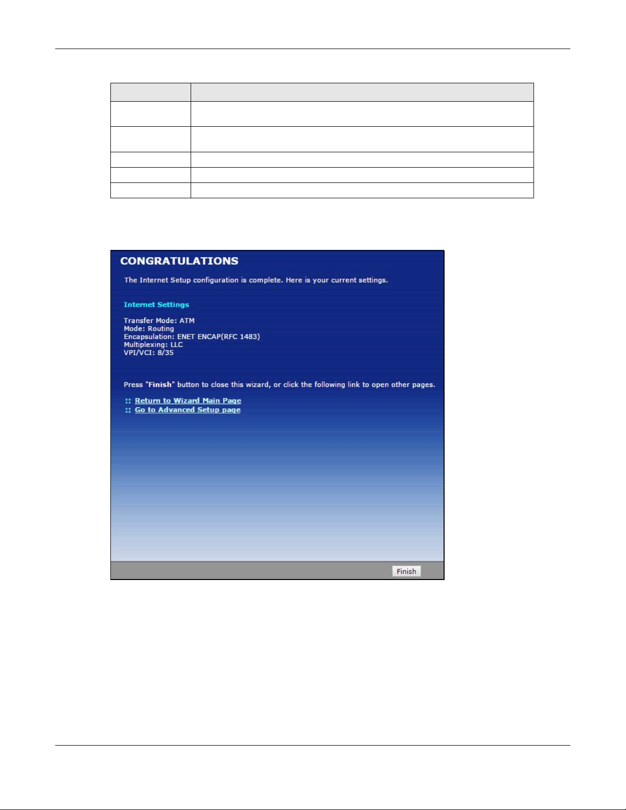
Chapter 4 Internet Setup Wizard
Table 12 Internet Connection with RFC 1483 (continued)
LABEL DESCRIPTION
First DNS Server Enter the IP addresses of the DNS servers. The DNS servers are passed to the
DHCP clients along with the IP address and the subnet mask.
Second DNS
Server
Back Click this to return to the previous screen without saving.
Apply Click this to save your changes.
Exit Click this to close the wizard screen without saving.
As above.
3 Use the read-only summary table to check whether what you have configured is correct. Click
Finish to complete and save the wizard setup.
Figure 22 Internet Access Setup Complete
4 Launch your web browser and navigate to www.zyxel.com. Internet access is just the beginning.
Refer to the rest of this guide for more detailed information on the complete range of P-79X
features. If you cannot access the Internet, open the web configurator again to confirm that the
Internet settings you configured in the wizard setup are correct.
P-79X Series User’s Guide
37
Page 38

5.1 Overview
A
B
5696/3200 Kpbs
This chapter describes:
• Configuring Point-to-point Connection, see page 38
• Configuring a Point-to-2points Connection, see page 40
Note: The tutorials featured in this chapter require a basic understanding of connecting to
and using the Web Configurator on your P-79X. For details, see the included Quick
Start Guide. For field descriptions of individual screens, see the related technical
reference in this User's Guide.
CHAPTER 5
Tutorials
5.2 Configuring Point-to-point Connection
In this scenario, Company A wants to set up a point-to-point connection with its br anch office B by
using two P-79Xs. The two P-79Xs are directly connected together through their DSL ports. The P79X on A’ s side is the server and the P-79X on B’ s side is the client. The maximum tr ansfer r ate for
the DSL connection between A and B is 5696 Kbps and the minimum transfer rate is 3200 Kbps.
To set up the point-to-point connection between A and B, you need to:
1 Set Up the Server.
2 Set Up the Client.
3 Connect the P-79Xs.
5.2.1 Set Up the Server
1 Log in to the server P-79X of Company A.
P-79X Series User’s Guide
38
Page 39
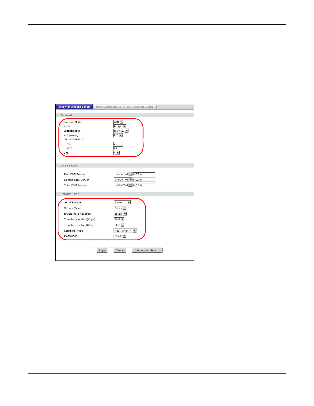
Chapter 5 Tutorials
2 Click Network > WAN > Internet Access Setup.
3 Configure the Internet Access Setup screen as the following. Select ATM as the Transfer Mode.
Select Bridge as the Mode. Configure the Multiplexing, Encapsulation, VPI, and VCI fields for
the point-to-point connection. Select 1 in the Line field as the DSL line you want the P-79X to use
as a default for outgoing traffic.
4 Then configure the Service Type section. Select 2 wire in the Service Mode field. In the Service
Type field, select Server. Select 5696 as the Transfer Max Rate and 3200 as the Transfer Min
Rate. Leave the rest of the fields set to their default settings. Click Apply.
Figure 23 WAN > Internet Access Setup
5.2.2 Set Up the Client
1 Log in to the client P-79X of branch office B.
2 Click Network > WAN > Internet Access Setup.
3 Select ATM as the Transfer Mode. Select Bridge as the Mode. Set the Multiplexing,
Encapsulation, VPI, and VCI to the same values you set in the server. Select 1 in the Line field
as the DSL line you want the P-79X to use as a default for outgoing traffic.
P-79X Series User’s Guide
39
Page 40

Chapter 5 Tutorials
4 Scroll down to the Service Type section. In the Service Mode field, select 2 wire, the same type
of connection you selected for the server. In the Service Type field, select Client. The rest of the
fields will be negotiated with the server. Click Apply.
5.2.3 Connect the P-79Xs
Connect the DSL ports on the P-79Xs together, and wait while the P-79Xs automatically establish
the connection. When the connection is established, the DSL1, DSL2, and INTERNET lights are
on. It takes up to half a minute to establish the connection. If the P-79Xs do not establish the
connection, verify that the settings (except the Service Type) match.
5.3 Configuring a Point-to-2points Connection
Now Company A has another branch office, C and wants to set up a point-to-2points connection
between a server P-79X on A’s side and client P-79Xs at B and C. The maximum transfer rate for
the DSL connection between A and B is 5696 Kbps and the minimum transfer rate is 3200 Kbps.
The maximum transfer rate for the DSL connection between A and C is 2560 Kbps and minimum
transfer rate is 1280 Kbps.
P-79X Series User’s Guide
40
Page 41
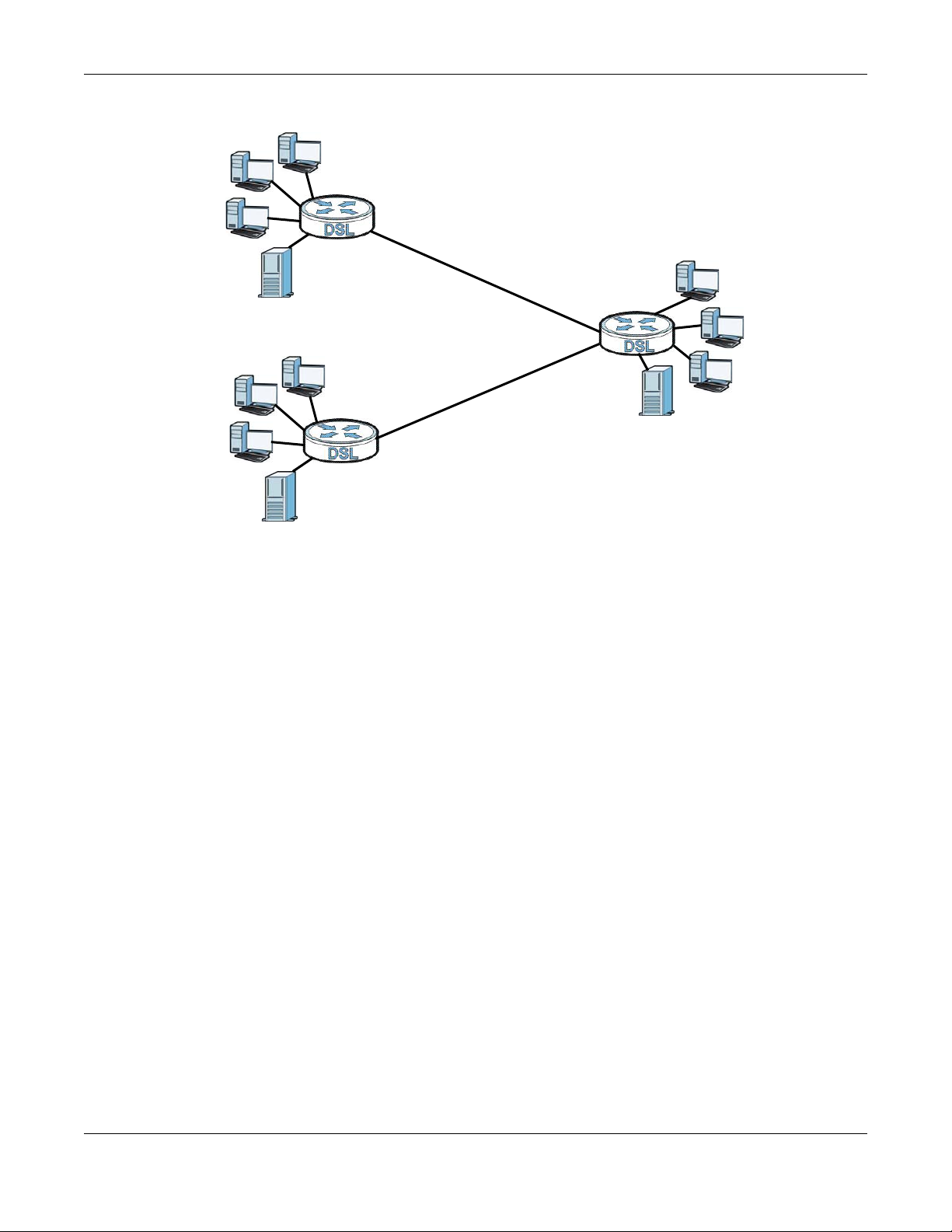
Chapter 5 Tutorials
B
A
C
5696/3200 Kpbs
2560/1280 Kpbs
To set up the point-to-2 point connection between A, B and C you need to:
1 Set up the Server.
2 Set up the Clients.
3 Connect the P-79Xs.
5.3.1 Set up the Server
1 Log in to the server P-79X of Company A.
2 Click Network > WAN > Internet Access Setup.
3 Configure the Internet Access Setup screen as the following. Select ATM as the Transfer Mode.
Select Bridge as the Mode. Configure the Multiplexing, Encapsulation, VPI, and VCI fields for
the point-to-point connection. Select 1 in the Line field as the DSL line you want the P-79X to use
as a default for outgoing traffic.
4 Then configure the Service Type section. Select 2 wire-2 line in the Service Mode field. In the
Service Type field, select Server. For Line1 configuration, select 5696 as the Transfer Max Rate
and 3200 as the Transfer Min Rate. For Line2 configuration, select 2560 as the Transfer Max
Rate and 1280 as the Transfer Min Rate. Leave the rest of the fields to their default settings.
Click Apply.
P-79X Series User’s Guide
41
Page 42

Chapter 5 Tutorials
Figure 24 WAN > Internet Access Setup
5.3.2 Set up the Clients
1 Log in to the client P-79X of branch office B.
2 Click Network > WAN > Internet Access Setup.
3 Select ATM as the Transfer Mode. Set the VPI, VCI, Multiplexing, and Encapsulation to the
same values you set in the server.
4 Scroll down to the Service Type section. In the Service Mode field, select 2 wire. In the Service
Type field, select Client. The rest of the fields will be negotiated with the server. Click Apply.
Figure 25 WAN > Internet Connection > Service Type of B
5 Repeat the above steps 1 to 4 for the second client P-79X on C’s side. The Service Type should
look like the following.
P-79X Series User’s Guide
42
Page 43

Figure 26 WAN > Internet Connection > Service Type of C
5.3.3 Connect the P-79Xs
Connect the DSL ports on the P-79Xs together, and wait while the P-79Xs automatically establish
the connection. Make sure that the Y-cable is connected to the proper DSL outlets. The Y-cable
connector marked DSL1 must be connected to the outgoing DSL 1 telephone jack and the Y-cable
connector marked DSL2 must be connected to the outgoing DSL 2 telephone jack.
When the connection is established, the DSL1, DSL2, and INTERNET lights turn on. It takes up to
half a minute to establish the connection. If the P-79Xs do not establish the connection, verify that
the settings are correct.
Chapter 5 Tutorials
P-79X Series User’s Guide
43
Page 44

PART II
Technical Reference
44
Page 45

6.1 Overview
WAN
LAN
This chapter describes how to configure WAN settings from the WAN screens. Use these screens to
configure your P-79X for Internet access.
A WAN (Wide Area Network) connection is an outside connection to another network or the
Internet. It connects your private networks (such as a LAN (Local Area Network) and other
networks, so that a computer in one location can communicate with computers in other locations.
Figure 27 LAN and WAN
CHAPTER 6
WAN Setup
6.1.1 What Yo u Can Do in the WAN Screens
•Use the Internet Access Setup screen (Section 6.2 on page 46) to configure the WAN settings
on the P-79X for Internet access.
•Use the More Connections screen (Section 6.3 on page 53) to set up additional Internet access
connections.
•Use the WAN Backup Setup screen (Section 6.4 on page 57) to set up a backup gateway that
helps forward traffic to its destination when the default WAN connection is down.
6.1.2 What You Need to Know About WAN
Encapsulation Method
Encapsulation is used to include data from an upper layer protocol into a lower layer protocol. To set
up a WAN connection to the Internet, you need to use the same encapsulation method used by your
ISP (Internet Service Provider). If your ISP offers a dial-up Internet connection using PPPoE (PPP
over Ethernet), they should also provide a username and password (and service name) for user
authentication.
P-79X Series User’s Guide
45
Page 46

Chapter 6 WAN Setup
WAN IP Address
The WAN IP address is an IP address for the P-79X, which makes it accessible from an outside
network. It is used by the P-79X to communicate with other devices in other networks. It can be
static (fixed) or dynamically assigned by the ISP each time the P-79X tries to access the Internet.
If your ISP assigns you a static WAN IP address, they should also assign you the subnet mask and
DNS server IP address(es) (and a gateway IP address if you use the Ethernet or ENET ENCAP
encapsulation method).
ATM
Asynchronous Transfer Mode (ATM) is a LAN and WAN networking technology that provides highspeed data transfer. ATM uses fixed-size packets of information called cells.
PTM
Packet Transfer Mode (PTM) is packet-oriented and supported by the VDSL2 standard. In PTM,
packets are encapsulated directly in the High-level Data Link Control (HDLC) frames. It is designed
to provide a low-overhead, transparent way of transporting packets over DSL links, as an
alternative to ATM.
Multicast
Traditionally, IP packets are transmitted in one of either two ways - Unicast (1 sender - 1 recipient)
or Broadcast (1 sender - everybody on the network). Multicast delivers IP packets to a group of
hosts on the network - not everybody and not just one.
IGMP
IGMP (Internet Group Multicast Protocol) is a network-laye r protocol used to establish membership
in a Multicast group - it is not used to carry user data. There are three versions of IGMP. IGMP
version 2 and 3 are improvements over version 1, but IGMP version 1 and 2 are still in wide use.
Finding Out More
See Section 6.5 on page 59 for technical background information on WAN.
6.1.3 Before You Begin
You need to know your Internet access settings such as encapsulation and W AN IP address. Get this
information from your ISP.
6.2 The Internet Access Setup Screen
Use this screen to change your P-79X’s WAN settings. Click Network > WAN > Internet Access
Setup. The screen differs by the WAN type and encapsulation you select.
P-79X Series User’s Guide
46
Page 47

Chapter 6 WAN Setup
Figure 28 Network > WAN >Internet Access Setup
The following table describes the labels in this screen.
Table 13 Network > WAN > Internet Access Setup
LABEL DESCRIPTION
General
Transfer Mode Select the transfer mode you want to use.
PTM (Packet Transfer Mode): The P-79X uses the SHDSL technology for data
transmission over the DSL port.
ATM (Asynchronous Transfer Mode): The P-79X uses the ADSL technology for
data transmission over the DSL port.
Select Auto if the P-79X uses the SHDSL or the ADSL technology for data
transmission over the DSL port.
P-79X Series User’s Guide
47
Page 48

Chapter 6 WAN Setup
Table 13 Network > WAN > Internet Access Setup (continued)
LABEL DESCRIPTION
Mode Select Routing (default) from the drop-down list box if your ISP giv es you one
IP address only and you want multiple computers to share an Internet account.
Select Bridge when your ISP provides you more than one IP address and you
want the connected computers to get individual IP address from ISP’s DHCP
server directly. If you select Bridge, you cannot use Firewall, DHCP server and
NAT on the P-79X.
Encapsulation Select the method of encapsulation used by your ISP from the drop-down list
User Name (PPPoA and PPPoE encapsulation only) Enter the user name exactly as your ISP
Password (PPPoA and PPPoE encapsulation only) Enter the password associated with the
Service Name (PPPoE only) Type the name of your PPPoE service here.
Multiplexing Select the method of multiplexing used by your ISP from the drop-down list.
Virtual Circuit ID VPI (Virtual Path Identifier) and VCI (Virtual Channel Identifier) define a virtual
VPI The valid range for the VPI is 0 to 255. Enter the VPI assigned to you.
VCI The valid range for the VCI is 32 to 65535 (0 to 31 is reserved for local
Tag VLAN ID for
egress packets
box. Choices vary depending on the mode you select in the Mode field.
If you select Bridge in the Mode field, select ENET ENCAP (RFC 1483).
If you select Routing in the Mode field, select ENET ENCAP (RFC 1483) or
PPPoE.
If you set up a point-to-point or a point-to-2points connection, select either
ENET ENCAP (RFC 1483).
assigned. If assigned a name in the form user@domain where domain
identifies a service name, then enter both components exactly as given.
user name above.
Choices are VC or LLC.
This is available only when you select ATM in the Transfer Mode field.
circuit. Refer to the appendix for more information.
This is available only when you select ATM in the Transfer Mode field.
management of ATM traffic). Enter the VCI assigned to you.
Select this option to add the VLAN tag (specified below) to the outgoing traffic
through this connection.
This is available only when you select PTM in the Transfer Mode field.
Enter 802.1P
Priority
Enter 802.1Q
VLAN ID
Line Select the DSL line you want the P-79X to use as a default for outgoing traffic
IP Address This option is available if you select
IEEE 802.1p defines up to 8 separate traffic types by inserting a tag into a
MAC-layer frame that contains bits to define class of service.
Type the IEEE 802.1p priority level (from 0 to 7) to add to traffic through this
connection. The greater the number, the higher the priority level.
Type the VLAN ID number (from 1 to 4094) for traffic through this connection.
(remote node 1).
Routing in the Mode field.
A static IP address is a fixed IP that your ISP gives you. A dynamic IP address
is not fixed; the ISP assigns you a different one each time you connect to the
Internet.
Select Obtain an IP Address Automatically if you have a dynamic IP
address; otherwise select Static IP Address and type your ISP assigned IP
address in the IP Address field below.
P-79X Series User’s Guide
48
Page 49

Chapter 6 WAN Setup
Table 13 Network > WAN > Internet Access Setup (continued)
LABEL DESCRIPTION
Subnet Mask This option is available if you select ENET ENCAP in the Encapsulation field.
Enter a subnet mask in dotted decimal notation.
Gateway IP
address
DNS Server
First DNS Server
Second DNS Server
Connection (PPPoE encapsulation only)
Nailed-Up
Connection
Connect on
Demand
Max Idle Timeout Specify an idle time-out in the Max Idle Timeout field when you select
Service Type
Service Mode
Service Type
Enable Rate
Adaption
Transfer Max Rate
(Kbps)
This option is available if you select ENET ENCAP in the Encapsulation field.
Specify a gateway IP address (supplied by your ISP).
Select Obtained From ISP if your ISP dynamically assigns DNS server
information (and the P-79X's WAN IP address) and you select Obtain an IP
Address Automatically.
Select User-Defined if you have the IP address of a DNS server. Enter the
DNS server's IP address in the field to the right. If you chose User-Defined,
but leave the IP address set to 0.0.0.0, User-Defined changes to None after
you click Apply. If you set a second choice to User-Defined, and enter the
same IP address, the second User-Defined changes to None after you click
Apply.
Select None if you do not want to configure DNS servers. You must have
another DNS server on your LAN, or else the computers must have their DNS
server addresses manually configured. If you do not configure a DNS server,
you must know the IP address of a computer in order to access it.
Select Nailed-Up Connection when you want your connection up all the time.
The P-79X will try to bring up the connection automatically i f it is disconne cted.
Select Connect on Demand when you don't want the connection up all the
time and specify an idle time-out in the Max Idle Timeo u t field.
Connect on Demand. The default setting is 0, which means the Internet
session will not timeout.
Select 2-wire, 4-wire or 2wire-2line mode for the DSL connection. This is
depends on the network configuration you want to set up and the phone lines
you use. Service mode affects the maximum speed of the connection. In 2-
wire mode, the maximum data rate is up to 5.69 Mbps, while in 4-wire mode,
the maximum data rate is up to 11.38 Mbps. In 2wire-2line mode the
maximum data rate is 5.69 Mbps for each line. See Section 6.2.1 on page 50
for more information on configuring 2wire-2line mode.
Indicate whether the P-79X is the server or the client in the DSL connection.
Select Server if this P-79X is the server in a point-to-point application.
Otherwise, select Client. This field is not configurable if you select 2wire-
2line mode because the ZyXEL Device is automatically set to Server.
This field is enabled if Service Type is Server. Indicate whether or not the P-
79X can adjust the speed of its connection to that of the other device.
This field is enabled if Service Type is Server. Set the maximum rate at whi ch
the P-79X sends and receives information. The actual transfer rate will be
between this value and the minimum transfer rate you configure.
When you select 4-wire in the Service Mode field, then the transfer rate you
set here is doubled. For example, select 5696 Kbps to configure a maximum
transfer rate of 11392 Kbps.
P-79X Series User’s Guide
49
Page 50

Table 13 Network > WAN > Internet Access Setup (continued)
LABEL DESCRIPTION
Transfer Min Rate
(Kbps)
Standard Mode
Modulation Select the modulation supported by your ISP.
Apply Click this to save your changes.
Cancel Click this to restore your previously saved settings.
Advanced Setup Click this to display the Advanced WAN Setup screen and edit more details
This field is enabled if Service Type is Server. Set the minimum rate at which
the P-79X sends and receives information. The actual transfer rate will be
between this value and the maximum transfer rate you configure.
When you select 4-wire in the Service Mode field, then the transfer rate you
set here is doubled. For example, select 192 Kbps to configure a minimum
transfer rate of 384 Kbps.
This field is enabled if Service Type is Server. Select the operational mode
the P-79X uses in the DSL connecti on. ANSI (ANNEX_A) refers to connections
over POTS and ETSI (ANNEX_B) refers to connections over ISDN lines.
of your WAN setup.
6.2.1 2Wire-2Line Service Mode
The Service Mode section of the Internet Connection screen allows you to set up two DSL
connections when you select 2wire-2line mode. This allows you to create a point-to-2points
configuration.
Chapter 6 WAN Setup
Figure 29 2wire-2line Service Mode
The following table describes the labels in this screen.
Table 14 2wire-2line Service Mode
LABEL DESCRIPTION
Service Type
Service Mode
Service Type
Line1 / Line 2
Select 2wire-2line mode for the DSL connection. This means that the P-79X
is going to be a server connected to two client P-79Xs.
When you select 2wire-2line mode this field automatically changes to Server
or Client.
You can configure different connection rate settings for Line 1 and Line 2 DSL
connections.
P-79X Series User’s Guide
50
Page 51

Chapter 6 WAN Setup
Table 14 2wire-2line Service Mode (continued)
LABEL DESCRIPTION
Enable Rate
Adaption
Transfer Max Rate
(Kbps)
Transfer Min Rate
(Kbps)
Standard Mode
Modulation
Apply Click Apply to save the changes.
Cancel Click Cancel to begin configuring this screen afresh.
Advanced Setup Click this button to displ ay the Advanced WAN Setup screen and edit more
Indicate whether or not the P-79X can adjust the speed of its connection to
that of the other device.
This field is enabled if Service Type is Server. Set the maximum rate at whi ch
the P-79X sends and receives information. The actual transfer rate will be
between this value and the minimum transfer rate you configure.
This field is enabled if Service Type is Server. Set the minimum rate at which
the P-79X sends and receives information. The actual transfer rate will be
between this value and the maximum transfer rate you configure.
Select the operational mode the P-79X uses in the DSL connection. Annex A
refers to connections over POTS and Annex B refers to connections over ISDN
lines.
Select the modulation supported by your ISP.
details of your WAN setup.
6.2.2 Advanced Internet Access Setup
Use this screen to edit your P-79X's advanced WAN settings. Click the Advanced Setup button in
the Internet Access Setup screen. The screen appears as shown.
Figure 30 Network > WAN > Internet Access Setup: Advanced Setup
P-79X Series User’s Guide
51
Page 52

Chapter 6 WAN Setup
The following table describes the labels in this screen.
Table 15 Network > WAN > Internet Access Setup: Advanced Setup
LABEL DESCRIPTION
RIP & Multicast
Setup
RIP Direction RIP (Routing Information Protocol) allows a router to exchange routing
RIP Version This field is not configurable if you select None in the RIP Direction field.
Multicast Multicast packets are sent to a group of computers on the LAN and are an
MTU
MTU The Maximum Transmission Unit (MTU) defines the size of the largest packet
This section is not available when you configure the P-79X to be in bridge
mode.
information with other routers. Use this field to control how much routing
information the P-79X sends and receives on the subnet.
Select the RIP direction from None, Both, In Only and Out Only.
Select the RIP version from RIP-1 and RIP-2.
alternative to unicast packets (packets sent to one computer) and broadcast
packets (packets sent to every computer).
Internet Group Multicast Protocol (IGMP) is a network-layer protocol used to
establish membership in a multicast group. The P-79X supports IGMP-v1,
IGMP-v2, IGMP-v3 and IGMP-all. Select None to disable it.
allowed on an interface or connection. Enter the MTU in this field.
For ENET ENCAP, the MTU value is 1500.
For PPPoE, the MTU value is 1492.
For PPPoA and RFC 1483, the MTU is 65535.
Packet Filter
Incoming Filter Sets
Protocol Filter Select the protocol filter(s) to control incoming traffic. You may choose up to 4
sets of filters.
You can configure packet filters in the Packet Filter screen. See Chapter 12 on
page 119 for more details.
Generic Filter Sele ct the generic filter(s) to control incoming traffic. You may choose up to 4
sets of filters.
You can configure generic filters in the Packet Filter screen. See Chapter 12
on page 119 for more details.
Outgoing Filter Sets
Protocol Filter Select the protocol filter(s) to control outgoing traffic. You may choose up to 4
Generic Filter Sele ct the generic filter(s) to control outgoing traffic. You may choose up to 4
Back Click this to return to the previous screen without saving.
Apply Click this to save your changes.
Cancel Click this to restore your prev iously saved settings.
sets of filters.
You can configure protocol filters in the Packet Filter screen. See Chapter 12
on page 119 for more details.
sets of filters.
You can configure generic filters in the Packet Filter screen. See Chapter 12
on page 119 for more details.
P-79X Series User’s Guide
52
Page 53

Chapter 6 WAN Setup
6.3 The More Connections Screen
The P-79X allows you to configure more than one Internet access connection. To configure
additional Internet access connections click Network > WAN > More Connections. The screen
differs by the encapsulation you select. When you use the WAN > Internet Access Setup screen
to set up Internet access, you are configuring the first WAN connection.
Figure 31 Network > WAN > More Connections
The following table describes the labels in this screen.
Table 16 Network > WAN > More Connections
LABEL DESCRIPTION
# This is an index number indicat in g the number of the corresponding connection.
Active This field indicates whether the connection is active or not.
Name This is the name you gave to the Internet connection.
PRI/VID PRI indicates the 802.1P priority level assigned to traffic sent through this
connection. This displays - when there is no priority level assigned.
VID indicates the 802.1Q VLAN ID number assigned to traffic sent through this
connection. This displays - when there is no VLAN ID number assign ed.
Encapsulation This field indicates the encapsulation method of the Internet connection.
Modify The first (ISP) connection is read-only in this screen. Use the WAN > Internet
Access Setup screen to edit it.
Click the Edit icon to edit the Internet connection settings. Click t h is icon on an
empty configuration to add a new Internet access setup.
Click the Remove icon to delete the Internet access setup from your connection
list.
Apply Click this to save your changes.
Cancel Click this to restore your previously saved settings.
6.3.1 More Connections Edit
Use this screen to configure a connection. Click the edit icon in the More Connections screen to
display the following screen.
P-79X Series User’s Guide
53
Page 54

Chapter 6 WAN Setup
Figure 32 Network > WAN > More Connections: Edit
The following table describes the labels in this screen.
Table 17 Network > WAN > More Connections: Edit
LABEL DESCRIPTION
# This is the index number of the WAN connections.
General
Active Select the check box to activate or clear the check box to deactivate this
connection.
Name Enter a unique, descriptive name of up to 13 ASCII characters for this
connection.
Mode Select Routing from the drop-down list box if your ISP allows multiple
Encapsulation Select the method of encapsulation used by your ISP from the drop-down
User Name (PPPoE encapsulation only) Enter the user name exactly as your ISP
Password (PPPoE encapsulation only) Enter the password associated with the user
Enter 802.1P Priority[0-7]Specify a priority level (between 0 and 7). "0" i s the lowest priority level
computers to share an Internet account.
If you select Bridge, the P-79X will forward any packet that it does not
route to this remote node; otherwise, the packets are discarded.
list box. Choices vary depending on the mode you select in the Mode
field.
If you select Bridge in the Mode field, select ENET ENCAP.
If you select Routing in the Mode field, select ENET ENCAP or PPPoE.
If you set up a point-to-point connection, select ENET ENCAP.
assigned. If assigned a name in the form user@domain where domain
identifies a service name, then enter both components exactly as given.
name above.
and "7" is the highest.
P-79X Series User’s Guide
54
Page 55

Chapter 6 WAN Setup
Table 17 Network > WAN > More Connections: Edit (continued)
LABEL DESCRIPTION
Enter 802.1Q VLAN
ID[1-4094]
IP Address This option is available if you select Routing in the Mode field.
Subnet Mask Enter a subnet mask in dotted decimal notation.
Connection
Nailed-Up Connection Select Nailed-Up Connection when you want your connection up all the
Connect on Demand Select Connect on Demand when you don't want the connection up all
Max Idle Timeout Specify an idle time-out in the Max Idle Timeout field when you select
NAT SUA only is available only when you select Routing in the Mode field.
Specify a VLAN ID number.
A static IP address is a fixed IP that your ISP gives you. A dynamic IP
address is not fixed; the ISP assigns you a different one each time you
connect to the Internet.
If you use the encapsulation type except ENET ENCAP, select Obtain an
IP Address Automatically when you have a dynamic IP address;
otherwise select Static IP Address and type your ISP assigned IP
address in the IP Address field below.
If you use ENET ENCAP, enter the IP address given by your ISP in the IP
Address field.
time. The P-79X will try to bring up the connection automatically if it is
disconnected.
the time and specify an idle time-out in the Max Idle Timeout field.
Connect on Demand. The default setting is 0, which means the Internet
session will not timeout.
Select SUA Only if you have one public IP address and want to use NAT.
Click Edit Detail to go to the Port Forwarding screen to edit a server
mapping set.
Otherwise, select None to disable NAT.
Back Click this to return to the previous screen without saving.
Apply Click this to save your changes.
Cancel Click this to restore your previously saved settings.
Advanced Setup Click this to display the More Connections Advanced Setup screen and
edit more details of your WAN setup.
6.3.2 Configuring More Connections Advanced Setup
Use this screen to edit your P-79X's advanced WAN settings. Click the Advanced Setup button in
the More Connections Edit screen. The screen appears as shown.
P-79X Series User’s Guide
55
Page 56

Chapter 6 WAN Setup
Figure 33 Network > WAN > More Connections: Edit: Advanced Setup
The following table describes the labels in this screen.
Table 18 Network > WAN > More Connections: Edit: Advanced Setup
LABEL DESCRIPTION
RIP Setup This section is not available when you configure the P-79X to be in bridge
RIP Direction Select the RIP direction from None, Both, In Only and Out Only.
RIP Version Select the RIP version from RIP-1, RIP-2B and RIP-2M.
MTU
MTU The Maximum Transmission Unit (MTU) defines the size of the largest
Packet Filter
Incoming Filter Sets
Protocol Filter Select the protocol filter(s) to control incoming traffic. You may choose up
Generic Filter Select the generic filter(s) to control incoming traffic. You may choose up
Outgoing Filter Sets
Protocol Filter Select the protocol filter(s) to control outgoing traffic. You may choose up
mode.
packet allowed on an interface or connection. Enter the MTU in this field.
For ENET ENCAP, the MTU value is 1500.
For PPPoE, the MTU value is 1492.
For PPPoA and RFC, the MTU is 65535.
to 4 sets of filters.
You can configure packet filters in the Packet Filter screen. See Chapter
12 on page 119 for more details.
to 4 sets of filters.
You can configure generic filters in the Packet Filter screen. See Chapter
12 on page 119 for more details.
to 4 sets of filters.
You can configure protocol filters in the Packet Filter screen. See Chapter
12 on page 119 for more details.
P-79X Series User’s Guide
56
Page 57

Chapter 6 WAN Setup
Table 18 Network > WAN > More Connections: Edit: Advanced Setup (continued)
LABEL DESCRIPTION
Generic Filter Select the generic filter(s) to control outgoing traffic. You may choose up
to 4 sets of filters.
You can configure generic filters in the Packet Filter screen. See Chapter
12 on page 119 for more details.
Back Click this to return to the previous screen without saving.
Apply Click this to save your changes.
Cancel Click this to restore your previously saved settings.
6.4 The WAN Backup Setup Screen
Use this screen to configure your P-79X’s WAN backup. Click Network > WAN > WAN Backup
Setup. This screen is not available if you set the WAN type to Ethernet in the Internet Access
Setup screen.
Note: This screen is not available when you use the P-791R v3 device.
Figure 34 Network > Internet (WAN) > WAN Backup
P-79X Series User’s Guide
57
Page 58

Chapter 6 WAN Setup
The following table describes the labels in this screen.
Table 19 Network > Internet (WAN) > WAN Backup
LABEL DESCRIPTION
Backup Type Select the method that the P-79X uses to check the DSL connection.
Select DSL Link to have the P-79X check if the connection to the DSLAM
is up. Select ICMP to have the P-79X periodically ping the IP addresses
configured in the Check WAN IP Address fields.
Check WAN IP Address1-3Configure this field to test your P-79X's WAN accessibility. Type the IP
address of a reliable nearby computer (for example, your ISP's DNS
server address).
If you activate eith er tr affi c redirect or dial b ackup , you mus t confi gure at
least one IP address here.
When using a WAN backup connection, the P-79X periodically pings the
addresses configured here and uses the other WAN backup connection (if
configured) if there is no response.
Fail T olerance Type the number of times (2 recommended) that your P-79X may ping the
IP addresses configured in the Check WAN IP Address field without
getting a response before switching to a WAN backup connection (or a
different WAN backup connection).
Recovery Interval When the P-79X is using a lower priority connection (usually a WAN
backup connection), it periodically checks whether or not it can use a
higher priority connection.
Type the number of seconds (30 recommended) for the P-79X to wait
between checks. Allow more time if your destination IP address handles
lots of traffic.
Timeout Type the number of seconds (3 recommended) for your P-79X to wait for
Traffic Redirect Traffic redirect forwards traffic to a backup gateway when the P-79X
Active Traffic Redirect Select this check box to have the P-79X use traffic redirect if the normal
a ping response from one of the IP addresses in the Check WAN IP
Address field before timing out the request. The WAN connection is
considered "down" after the P-79X times out the number of times
specified in the Fail Tolerance field. Use a higher value in this field if
your network is busy or congested.
cannot connect to the Internet.
WAN connection goes down.
Note: If you activate traffic redirect, y ou must configure at
least one Check WAN IP Address.
Metric This field sets this route's priority among the routes the P-79X uses.
The metric represents the "cost of transmission". A router determines the
best route for transmission by choosing a pat h with the lowe st "cost". RIP
routing uses hop count as the measurement of cost, with a minimum of
"1" for directly connected networks. The number must be between "1"
and "15"; a number greater than "15" means the link is down. The smaller
the number, the lower the "cost".
Backup Gateway Type the IP address of your backup gateway in dotted decimal notation.
The P-79X automatically forwards traffic to this IP address if the P-79X's
Internet connection terminates.
Apply Click Apply to save the changes.
Cancel Click Cancel to begin configuring this screen afresh.
P-79X Series User’s Guide
58
Page 59

Chapter 6 WAN Setup
6.5 WAN Technical Reference
This section provides some technical background information about the topics covered in this
chapter.
6.5.1 Encapsulation
Be sure to use the encapsulation method required by your ISP. The P-79X supports the following
methods.
6.5.1.1 ENET ENCAP
The MAC Encapsulated Routing Link Protocol (ENET ENCAP) is only implemented with the IP
network protocol. IP packets are routed between the Ethernet interface and the WAN interface and
then formatted so that they can be understood in a bridged environment. For instance, it
encapsulates routed Ethernet frames into bridged ATM cells. ENET ENCAP requires that you specify
a gateway IP address in the Gateway IP Address field in the wizard or WAN screen. You can get
this information from your ISP.
6.5.1.2 PPP over Ethernet
The P-79X supports PPPoE (Point-to-Point Protocol over Ethernet). PPPoE is an IETF Draft standard
(RFC 2516) specifying how a personal computer (PC) interacts with a broadband modem (DSL,
cable, wireless, etc.) connection. The PPPoE option is for a dial-up connection using PPPoE.
For the service provider, PPPoE offers an access and authentication method that works with existing
access control systems (for example RADIUS).
One of the benefits of PPPoE is the ability to let you access one of multiple network services, a
function known as dynamic service selection. This enables the service provider to easily create and
offer new IP services for individuals.
Operationally, PPPoE saves significant effort for both you and the ISP or carrier, as it requires no
specific configuration of the broadband modem at the customer site.
By implementing PPP oE directly on the P-79X (r ather than individual computers), the computers on
the LAN do not need PPPoE software installed, since the P-79X does that part of the task.
Furthermore, with NAT, all of the LANs’ computers will have access.
6.5.1.3 RFC 1483
RFC 1483 describes two methods for Multiprotocol Encapsulation over ATM Adaptation Layer 5
(AAL5). The first method allows multiplexing of multiple protocols over a single ATM virtual circuit
(LLC-based multiplexing) and the second method assumes that each protocol is carried over a
separate ATM virtual circuit (VC-based multiplexing). Please refer to RFC 1483 for more detailed
information.
P-79X Series User’s Guide
59
Page 60

6.5.2 Multiplexing
There are two conventions to identify what protocols the virtual circuit (VC) is carrying. Be sure to
use the multiplexing method required by your ISP.
VC-based Multiplexing
In this case, by prior mutual agreement, each protocol is assigned to a specific virtual circuit; for
example, VC1 carries IP, etc. VC-based multiplexing may be dominant in environments where
dynamic creation of large numbers of ATM VCs is fast and economical.
LLC-based Multiplexing
In this case one VC carries multiple protocols with protocol identifying information being contained
in each packet header. Despite the extra bandwidth and processing overhead, this method may be
advantageous if it is not practical to have a separate VC for each carried protocol, for example, if
charging heavily depends on the number of simultaneous VCs.
6.5.3 VPI and VCI
Chapter 6 WAN Setup
Be sure to use the correct Virtual Path Identifier (VPI) and Virtual Channel Identifier (VCI) numbers
assigned to you. The valid range for the VPI is 0 to 255 and for the VCI is 32 to 65535 (0 to 31 is
reserved for local management of AT M traffic). Please see the appendix for more information.
6.5.4 IP Address Assignment
A static IP is a fixed IP that your ISP gives you. A dynamic IP is not fixed; the ISP assigns you a
different one each time. The Single User Account feature can be enabled or disabled if you have
either a dynamic or static IP. However the encapsulation method assigned influences your choices
for IP address and ENET ENCAP gateway.
IP Assignment with PPPoE Encapsulation
If you have a dynamic IP, then the IP Address and Gateway IP Address fields are not applicable
(N/A). If you have a static IP, then you only need to fill in the IP Address field and not the
Gateway IP Address field.
IP Assignment with RFC 1483 Encapsulation
In this case the IP address assignment must be static.
IP Assignment with ENET ENCAP Encapsulation
In this case you can have either a static or dynamic IP. For a static IP you must fill in all the IP
Address and Gateway IP Address fields as supplied by your ISP. However for a dynamic IP, the
P-79X acts as a DHCP client on the WAN port and so the IP Address and Gateway IP Address
fields are not applicable (N/A) as the DHCP server assigns them to the P-79X.
P-79X Series User’s Guide
60
Page 61

Chapter 6 WAN Setup
6.5.5 Nailed-Up Connection (PPP)
A nailed-up connection is a dial-up line where the connection is always up regardless of traffic
demand. The P-79X does two things when you specify a nailed-up connection. The first is that idle
timeout is disabled. The second is that the P-79X will try to bring up the connection when turned on
and whenever the connection is down. A nailed-up connection can be very expensive for obvious
reasons.
Do not specify a nailed-up connection unless your telephone company offers flat-r ate service or you
need a constant connection and the cost is of no concern.
6.5.6 NAT
NAT (Network Address Translation - NAT, RFC 1631) is the translation of the IP address of a host in
a packet, for example, the source address of an outgoing packet, used within one network to a
different IP address known within another network.
6.6 Metric
The metric represents the "cost of transmission". A router determines the best route for
transmission by choosing a path with the lowest "cost". RIP routing uses hop count as the
measurement of cost, with a minimum of "1" for directly connected networks. The number must be
between "1" and "15"; a number greater than "15" means the link is down. The smaller the
number, the lower the "cost".
The metric sets the priority for the P-79X’s routes to the Internet. If any two of the default routes
have the same metric, the P-79X uses the following pre-defined priorities:
• Normal route: designated by the ISP (see Section 6.2 on page 46)
• Traffic-redirect route (see Section 6.7 on page 61)
For example, if the normal route has a of "1" and the traffic-redirect route has a metric of "2", then
the normal route acts as the primary default route. If the normal route fails to connect to the
Internet, the P-79X tries the traffic-redirect route next.
If you want the traffic-redirect route route to take priority o ver the normal route, all y ou need to do
is set the traffic-redirect route’s metric to "1" and the normal route to "2".
IP Policy Routing overrides the default routing behavior and takes priority over all of the routes
mentioned above.
6.7 Traffic Redirect
T raffic redirect forw ards traffic to a backup gateway when the P-79X cannot connect to the Internet.
An example is shown in the figure below.
P-79X Series User’s Guide
61
Page 62

Chapter 6 WAN Setup
Figure 35 Traffic Redirect Example
The following network topology allows you to avoid triangle route security issues when the backup
gateway is connected to the LAN. Use IP alias to configure the LAN into two or three logical
networks with the P-79X itself as the gateway for each LAN network. Put the protected LAN in one
subnet (Subnet 1 in the following figure) and the backup gateway in another subnet (Subnet 2).
Configure filters that allow packets from the protected LAN (Subnet 1) to the backup gateway
(Subnet 2).
Figure 36 Traffic Redirect LAN Setup
6.8 Traffic Shaping
T raffic Shaping is an agreement between the carrier and the subscriber to regulate the average r ate
and fluctuations of data transmission over an ATM network. This agreement helps eliminate
congestion, which is important for transmission of real time data such as audio and video
connections.
Peak Cell Rate (PCR) is the maximum rate at which the sender can send cells. This parameter may
be lower (but not higher) than the maximum line speed. 1 ATM cell is 53 bytes (424 bits), so a
maximum speed of 832Kbps gives a maximum PCR of 1962 cells/sec. This rate is not guaranteed
because it is dependent on the line speed.
P-79X Series User’s Guide
62
Page 63

Chapter 6 WAN Setup
Sustained Cell Rate (SCR) is the mean cell rate of each bursty traffic source. It specifies the
maximum average rate at which cells can be sent over the virtual connection. SCR may not be
greater than the PCR.
Maximum Burst Size (MBS) is the maximum number of cells that can be sent at the PCR. After MBS
is reached, cell rates fall below SCR until cell rate averages to the SCR again. At this time, more
cells (up to the MBS) can be sent at the PCR again.
If the PCR, SCR or MBS is set to the default of "0", the system will assign a maximum value that
correlates to your upstream line rate.
The following figure illustrates the relationship between PCR, SCR and MBS.
Figure 37 Example of Traffic Shaping
6.8.1 ATM Traffic Classes
These are the basic ATM traffic classes defined by the ATM Forum Traffic Management 4.0
Specification.
Constant Bit Rate (CBR)
Constant Bit Rate (CBR) provides fixed bandwidth that is always available even if no data is being
sent. CBR traffic is generally time-sensitive (doesn't tolerate delay). CBR is used for connections
that continuously require a specific amount of bandwidth. A PCR is specified and if traffic exceeds
this rate, cells may be dropped. Examples of connections that need CBR would be high-resolution
video and voice.
Variable Bit Rate (VBR)
The Variable Bit R ate (VBR) ATM traffic class is used with bursty connections. Connections that use
the Variable Bit Rate (VBR) traffic class can be grouped into real time (VBR-RT) or non-real time
(VBR-nRT) connections.
The VBR-RT (real-time Variable Bit Rate) type is used with bursty connections that require closely
controlled delay and delay variation. It also provides a fixed amount of bandwidth (a PCR is
specified) but is only available when data is being sent. An example of an VBR -R T connection would
be video conferencing. Video conferencing requires real-time data transfers and the bandwidth
requirement varies in proportion to the video image's changing dynamics.
P-79X Series User’s Guide
63
Page 64

Chapter 6 WAN Setup
The VBR-nRT (non real-time Variable Bit Rate) type is used with bursty connections that do not
require closely controlled delay and delay variation. It is commonly used for "bursty" traffic typical
on LANs. PCR and MBS define the burst levels, SCR defines the minimum level. An example of an
VBR-nRT connection would be non-time sensitive data file transfers.
Unspecified Bit Rate (UBR)
The Unspecified Bit Rate (UBR) ATM traffic class is for bursty data transfers. However, UBR doesn't
guarantee any bandwidth and only delivers traffic when the network has spare bandwidth. An
example application is background file transfer.
P-79X Series User’s Guide
64
Page 65

7.1 Overview
WAN
3G
This chapter discusses the P-79X’s WWAN screens. Use these screens to configure your P-79X for
Internet access.
A WAN (Wide Area Network) connection is an outside connection to another network or the
Internet. It connects your private networks, such as a LAN (Local Area Network) and other
networks, so that a computer in one location can communicate with computers in other locations.
Figure 38 LAN and WAN
CHAPTER 7
WWAN
3G standards for the sending and receiving of voice, video, and data in a mobile environment.
You can attach a 3G wireless adapter to the USB port and set the P-79X to use this 3G connection
as your WAN or a backup when the wired WAN connection fails.
Figure 39 3G WAN Connection
P-79X Series User’s Guide
65
Page 66

Chapter 7 WWAN
7.1.1 What You Can Do in this Chapter
•Use the 3G WAN Setup screen to configure 3G WAN connection (Section 7.2 on page 67).
Table 20 WAN Setup Overview
LAYER-2 INTERFACE INTERNET CONNECTION
CONNECTION
ADSL/VDSL
over PTM
ADSL over ATM EoA Routing PPPoE ATM PVC configuration, PPP
Ethernet
GbE N/A Routing IPoE/PPPoE PPP information, IPv4/IPv6 IP
3G N/A Nailed Up PPP/IPoE Dial string, APN (Access Point
DSL LINK
TYPE
N/A Routing PPPoE PPP information, IPv4/IPv6 IP
N/A
MODE ENCAPSULATION CONNECTION SETTINGS
address, routing feature, DNS
server, VLAN, QoS, and MTU
IPoE IPv4/IPv6 IP address, routing
feature, DNS server, VLAN, QoS,
and MTU
Bridge N/A VLAN and QoS
information, IPv4/IPv6 IP address,
routing feature, DNS server, VLAN,
QoS, and MTU
IPoE/IPoA ATM PVC configuration, IPv4/IPv6
IP address, routing feature, DNS
server, VLAN, QoS, and MTU
Bridge N/A ATM PVC configuration, and QoS
Routing PPPoE PPP user name and password, WAN
IPv4/IPv6 IP address, routing
feature, DNS server, VLAN, QoS,
and MTU
IPoE WAN IPv4/IPv6 IP address, NAT,
DNS server and routing feature
Bridge N/A VLAN and QoS
address, routing feature, DNS
server, VLAN, QoS, and MTU
Bridge N/A VLAN and QoS
Name), IP address, DNS server
On Demand PPP/IPoE Dial string, APN, Maximum idle
time out, DNS server, IP address
7.1.2 What Yo u Need to Know
The following terms and concepts may help as you read this chapter.
Encapsulation Method
Encapsulation is used to include data from an upper layer protocol into a lower layer protocol. To set
up a WAN connection to the Internet, you need to use the same encapsulation method used by your
ISP (Internet Service Provider). If your ISP offers a dial-up Internet connection using PPPoE (PPP
over Ethernet), they should also provide a username and password (and service name) for user
authentication.
P-79X Series User’s Guide
66
Page 67

Chapter 7 WWAN
WAN IP Address
The WAN IP address is an IP address for the P-79X, which makes it accessible from an outside
network. It is used by the P-79X to communicate with other devices in other networks. It can be
static (fixed) or dynamically assigned by the ISP each time the P-79X tries to access the Internet.
If your ISP assigns you a static WAN IP address, they should also assign you the subnet mask and
DNS server IP address(es).
ATM
Asynchronous Transfer Mode (ATM) is a WAN networking technology that provides high-speed data
transfer. ATM uses fixed-size packets of information called cells. With ATM, a high QoS (Quality of
Service) can be guaranteed. ATM uses a connection-oriented model and establishes a virtual circuit
(VC) between Finding Out More
PTM
Packet Transfer Mode (PTM) is packet-oriented and supported by the VDSL2 standard. In PTM,
packets are encapsulated directly in the High-level Data Link Control (HDLC) frames. It is designed
to provide a low-overhead, transparent way of transporting packets over DSL links, as an
alternative to ATM.
3G
3G (Third Generation) is a digital, packet-switched wireless technology. Bandwidth usage is
optimized as multiple users share the same channel and bandwidth is only allocated to users when
they send data. It allows fast transfer of voice and non-voice data and provides broadband Internet
access to mobile devices.
7.1.3 Before You Begin
You need to know your Internet access settings such as encapsulation and W AN IP address. Get this
information from your ISP.
7.2 The 3G WAN Setup Screen
The USB port (at the rear panel of the P-79X) allow you to attach a 3G dongle to wirelessly connect
to a 3G network for Internet access. You can have the P-79X use the 3G WAN connection as a
backup. Disconnect the DSL and Ethernet WAN ports to use the 3G dongle as your primary WAN
connection. The P-79X automatically uses a wired WAN connection when available.
P-79X Series User’s Guide
67
Page 68

Chapter 7 WWAN
3G
Note: This P-79X supports connecting one 3G dongle at a time.
Figure 40 Internet Access Application: 3G WAN
Use this screen to configure your 3G settings. Click Network > WWAN > 3G WAN Setup.
Note: The actual data rate you obtain varies depending the 3G card you use, the signal
strength to the service provider’s base station, and so on.
Figure 41 Network > WWAN > 3G WAN Setup
The following table describes the labels in this screen.
Table 21 Network Setting > WWAN > 3G Backup
LABEL DESCRIPTION
General
Active 3G WAN Select this check box to have the P-79X use the 3G connection as your WAN or a backup
Dial Number Enter the phone number (dial strin g) us ed to dial u p a connec tion to y ou r servi ce pro vider’s
Access Point
Name
when the wired WAN connection fails.
base station. Your ISP should provide the phone number.
For example, *99# is the dial string to establish a GPRS or 3G connection in Taiwan.
Enter the Access Point Name (APN) provided by your service provider. Connections with
different APNs may provide different services (such as Internet access or MMS (Multi-Media
Messaging Service)) and charge method.
You can enter up to 32 ASCII printable characters. Spaces are allowed.
P-79X Series User’s Guide
68
Page 69

Chapter 7 WWAN
Table 21 Network Setting > WWAN > 3G Backup (continued)
LABEL DESCRIPTION
PIN A PIN (Personal Identification Number) code is a key to a 3G card. Without the PIN code,
you cannot use the 3G card.
If your ISP enabled PIN code authentication, enter the 4-digit PIN code (0000 for example)
provided by your ISP. If you enter the PIN code incorrectly, the 3G card may be blocked by
your ISP and you cannot use the account to access the Internet.
If your ISP disabled PIN code authentication, leave this field blank.
Keep Alive
Interval
Keep Alive
Server
Auth Mode Select On to enable the authentication. Otherwise, select Off.
Username This is available only when you select On in the Auth Mode field.
Password This is available only when you select On in the Auth Mode field.
Apply Click Apply to save your changes back to the P-79X.
Cancel Click Cancel to return to the previous configuration.
Specify the time interval (in minutes) for checking whether the 3G connection is valid or
not.
Specify the DNS server address for checking the 3G connection status.
Type the user name (of up to 64 ASCII printable characters) given to you by your service
provider.
Type the password (of up to 64 ASCII printable characters) associated with the user name
above.
7.3 Technical Reference
The following section contains additional technical information about the P-79X features described
in this chapter.
Encapsulation
Be sure to use the encapsulation method required by your ISP . The P-79X can work in bridge mode
or routing mode. When the P-79X is in routing mode, it supports the following methods.
IP over Ethernet
IP over Ethernet (IPoE) is an alternative to PPPoE. IP packets are being delivered across an
Ethernet network, without using PPP encapsulation. They are routed between the Ethernet interface
and the WAN interface and then formatted so that they can be understood in a bridged
environment. For instance, it encapsulates routed Ethernet frames into bridged Ethernet cells.
PPP over Ethernet (PPPoE)
Point-to-Point Protocol over Ethernet (PPPoE) provides access control and billing functionality in a
manner similar to dial-up services using PPP. PPPoE is an IETF standard (RFC 2516) specifying how
a personal computer (PC) interacts with a broadband modem (DSL, cable, wireless, etc.)
connection.
P-79X Series User’s Guide
69
Page 70

Chapter 7 WWAN
For the service provider, PPPoE offers an access and authentication method that works with existing
access control systems (for example RADIUS).
One of the benefits of PPPoE is the ability to let you access one of multiple network services, a
function known as dynamic service selection. This enables the service provider to easily create and
offer new IP services for individuals.
Operationally, PPPoE saves significant effort for both you and the ISP or carrier, as it requires no
specific configuration of the broadband modem at the customer site.
By implementing PPP oE directly on the P-79X (r ather than individual computers), the computers on
the LAN do not need PPPoE software installed, since the P-79X does that part of the task.
Furthermore, with NAT, all of the LANs’ computers will have access.
RFC 1483
RFC 1483 describes two methods for Multiprotocol Encapsulation over ATM Adaptation Layer 5
(AAL5). The first method allows multiplexing of multiple protocols over a single ATM virtual circuit
(LLC-based multiplexing) and the second method assumes that each protocol is carried over a
separate ATM virtual circuit (VC-based multiplexing). Please refer to RFC 1483 for more detailed
information.
Multiplexing
There are two conventions to identify what protocols the virtual circuit (VC) is carrying. Be sure to
use the multiplexing method required by your ISP.
VC-based Multiplexing
In this case, by prior mutual agreement, each protocol is assigned to a specific virtual circuit; for
example, VC1 carries IP, etc. VC-based multiplexing may be dominant in environments where
dynamic creation of large numbers of ATM VCs is fast and economical.
LLC-based Multiplexing
In this case one VC carries multiple protocols with protocol identifying information being contained
in each packet header. Despite the extra bandwidth and processing overhead, this method may be
advantageous if it is not practical to have a separate VC for each carried protocol, for example, if
charging heavily depends on the number of simultaneous VCs.
T raffic Shaping
T raffic Shaping is an agreement between the carrier and the subscriber to regulate the average r ate
and fluctuations of data transmission over an ATM network. This agreement helps eliminate
congestion, which is important for transmission of real time data such as audio and video
connections.
Peak Cell Rate (PCR) is the maximum rate at which the sender can send cells. This parameter may
be lower (but not higher) than the maximum line speed. 1 ATM cell is 53 bytes (424 bits), so a
maximum speed of 832Kbps gives a maximum PCR of 1962 cells/sec. This rate is not guaranteed
because it is dependent on the line speed.
P-79X Series User’s Guide
70
Page 71
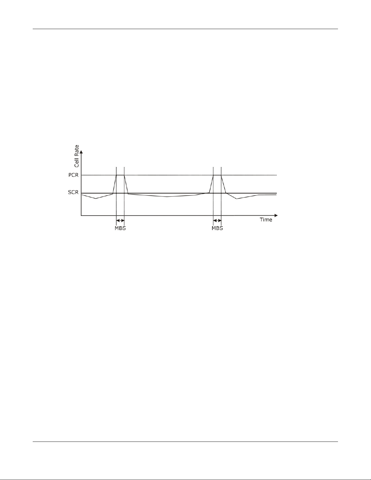
Chapter 7 WWAN
Sustained Cell Rate (SCR) is the mean cell rate of each bursty traffic source. It specifies the
maximum average rate at which cells can be sent over the virtual connection. SCR may not be
greater than the PCR.
Maximum Burst Size (MBS) is the maximum number of cells that can be sent at the PCR. After MBS
is reached, cell rates fall below SCR until cell rate averages to the SCR again. At this time, more
cells (up to the MBS) can be sent at the PCR again.
If the PCR, SCR or MBS is set to the default of "0", the system will assign a maximum value that
correlates to your upstream line rate.
The following figure illustrates the relationship between PCR, SCR and MBS.
Figure 42 Example of Traffic Shaping
ATM Traffic Classes
These are the basic ATM traffic classes defined by the ATM Forum Traffic Management 4.0
Specification.
Constant Bit Rate (CBR)
Constant Bit Rate (CBR) provides fixed bandwidth that is always available even if no data is being
sent. CBR traffic is generally time-sensitive (doesn't tolerate delay). CBR is used for connections
that continuously require a specific amount of bandwidth. A PCR is specified and if traffic exceeds
this rate, cells may be dropped. Examples of connections that need CBR would be high-resolution
video and voice.
Variable Bit Rate (VBR)
The Variable Bit R ate (VBR) ATM traffic class is used with bursty connections. Connections that use
the Variable Bit Rate (VBR) traffic class can be grouped into real time (VBR-RT) or non-real time
(VBR-nRT) connections.
The VBR-RT (real-time Variable Bit Rate) type is used with bursty connections that require closely
controlled delay and delay variation. It also provides a fixed amount of bandwidth (a PCR is
specified) but is only available when data is being sent. An example of an VBR -R T connection would
be video conferencing. Video conferencing requires real-time data transfers and the bandwidth
requirement varies in proportion to the video image's changing dynamics.
P-79X Series User’s Guide
71
Page 72

Chapter 7 WWAN
The VBR-nRT (non real-time Variable Bit Rate) type is used with bursty connections that do not
require closely controlled delay and delay variation. It is commonly used for "bursty" traffic typical
on LANs. PCR and MBS define the burst levels, SCR defines the minimum level. An example of an
VBR-nRT connection would be non-time sensitive data file transfers.
Unspecified Bit Rate (UBR)
The Unspecified Bit Rate (UBR) ATM traffic class is for bursty data transfers. However, UBR doesn't
guarantee any bandwidth and only delivers traffic when the network has spare bandwidth. An
example application is background file transfer.
IP Address Assignment
A static IP is a fixed IP that your ISP gives you. A dynamic IP is not fixed; the ISP assigns you a
different one each time. The Single User Account feature can be enabled or disabled if you have
either a dynamic or static IP. However the encapsulation method assigned influences your choices
for IP address and default gateway.
Introduction to VLANs
A Virtual Local Area Network (VLAN) allows a physical network to be partitioned into multiple logical
networks. Devices on a logical network belong to one group. A device can belong to more than one
group. With VLAN, a device cannot directly talk to or hear from devices that are not in the same
group(s); the traffic must first go through a router.
In Multi-Tenant Unit (MTU) applications, VLAN is vital in providing isolation and security among the
subscribers. When properly configured, VLAN prevents one subscriber from accessing the network
resources of another on the same LAN, thus a user will not see the printers and hard disks of
another user in the same building.
VLAN also increases network performance by limiting broadcasts to a smaller and more
manageable logical broadcast domain. In traditional switched environments, all broadcast packets
go to each and every individual port. With VLAN, all broadcasts are confined to a specific broadcast
domain.
Introduction to IEEE 802.1Q Tagged VLAN
A tagged VLAN uses an explicit tag (VLAN ID) in the MAC header to identify the VLAN membership
of a frame across bridges - they are not confined to the switch on which they were created. The
VLANs can be created statically by hand or dynamically through GVRP. The VLAN ID associates a
frame with a specific VLAN and provides the information that switches need to process the frame
across the network. A tagged frame is four bytes longer than an untagged frame and contains two
bytes of TPID (Tag Protocol Identifier), residing within the type/length field of the Ethernet frame)
and two bytes of TCI (Tag Control Information), starts after the source address field of the Ethernet
frame).
The CFI (Canonical Format Indicator) is a single-bit flag, always set to zero for Ethernet switches. If
a frame received at an Ethernet port has a CFI set to 1, then that frame should not be forwarded as
it is to an untagged port. The remaining twelve bits define the VLAN ID, giving a possible maximum
number of 4,096 VLANs. Note that user priority and VLAN ID are independent of each other. A
frame with VID (VLAN Identifier) of null (0) is called a priority frame, meaning that only the priority
level is significant and the default VID of the ingress port is given as the VID of the frame. Of the
P-79X Series User’s Guide
72
Page 73

Chapter 7 WWAN
4096 possible VIDs, a VID of 0 is used to identify priority frames and value 4095 (FFF) is reserved,
so the maximum possible VLAN configurations are 4,094.
TPID
2 Bytes
User Priority
3 Bits
CFI
1 Bit
VLAN ID
12 Bits
Multicast
IP packets are transmitted in either one of two ways - Unicast (1 sender - 1 recipient) or Broadcast
(1 sender - everybody on the network). Multicast delivers IP packets to a group of hosts on the
network - not everybody and not just 1.
Internet Group Multicast Protocol (IGMP) is a network-layer protocol used to establish membership
in a Multicast group - it is not used to carry user data. IGMP version 2 (RFC 2236) is an
improvement over version 1 (RFC 1112) but IGMP version 1 is still in wide use. If you would like to
read more detailed information about interoperability between IGMP version 2 and version 1, please
see sections 4 and 5 of RFC 2236. The class D IP address is used to identify host groups and can be
in the range 224.0.0.0 to 239.255.255.255. The address 224.0.0.0 is not assigned to any group
and is used by IP multicast computers. The address 224.0.0.1 is used for query messages and is
assigned to the permanent group of all IP hosts (including gateways). All hosts must join the
224.0.0.1 group in order to participate in IGMP. The address 224.0.0.2 is assigned to the multicast
routers group.
At start up, the P-79X queries all directly connected networks to gather group membership. After
that, the P-79X periodically updates this information.
DNS Server Address Assignment
Use Domain Name System (DNS) to map a domain name to its corresponding IP address and vice
versa, for instance, the IP address of www.zyxel.com is 204.217.0.2. The DNS server is extremely
important because without it, you must know the IP address of a computer before you can access
it.
The P-79X can get the DNS server addresses in the following ways.
1 The ISP tells you the DNS server addresses, usually in the form of an information sheet, when you
sign up. If your ISP gives you DNS server addresses, manually enter them in the DNS server fields.
2 If your ISP dynamically assigns the DNS server IP addresses (along with the P-79X’s WAN IP
address), set the DNS server fields to get the DNS server address from the ISP.
P-79X Series User’s Guide
73
Page 74

8.1 Overview
DSL
LAN
A Local Area Network (LAN) is a shared communication system to which many networking devices
are connected. It is usually located in one immediate area such as a building or floor of a building.
Use the LAN screens to help you configure a LAN DHCP server and manage IP addresses.
CHAPTER 8
LAN Setup
8.1.1 What You Can Do in the LAN Screens
•Use the IP screen (Section 8.2 on page 75) to set the LAN IP address and subnet mask of your
ZyXEL device. You can also edit your P-79X's RIP, multicast, any IP and Windows Networking
settings from this screen.
•Use the DHCP Setup screen (Section 8.3 on page 78) to configure the ZyXEL Device’s DHCP
settings.
•Use the Client List screen (Section 8.4 on page 80) to assign IP addresses on the LAN to specific
individual computers based on their MAC Addresses.
•Use the IP Alias screen (Section 8.5 on page 81) to change your P-79X’s IP alias settings.
8.1.2 What Yo u Need To Know About LAN
IP Address
IP addresses identify individual devices on a network. Every networking device (including
computers, servers, routers, printers, etc.) needs an IP address to communicate across the
network. These networking devices are also known as hosts.
P-79X Series User’s Guide
74
Page 75

Chapter 8 LAN Setup
Subnet Mask
Subnet masks determine the maximum number of possible hosts on a network. You can also use
subnet masks to divide one network into multiple sub-networks.
DHCP
A DHCP (Dynamic Host Configuration Protocol) server can assign your P-79X an IP address, subnet
mask, DNS and other routing information when it's turned on.
RIP
RIP (Routing Information Protocol) allows a router to exchange routing information with other
routers.
Multicast
Traditionally, IP packets are transmitted in one of either two ways - Unicast (1 sender - 1 recipient)
or Broadcast (1 sender - everybody on the network). Multicast delivers IP packets to a group of
hosts on the network - not everybody and not just 1.
IGMP
IGMP (Internet Group Multicast Protocol) is a network-laye r protocol used to establish membership
in a Multicast group - it is not used to carry user data. There are three versions of IGMP. IGMP
version 2 and 3 are improvements over version 1, but IGMP version 1 is still in wide use.
DNS
DNS (Domain Name System) is for mapping a domain name to its corresponding IP address and
vice versa. The DNS server is extremely important because without it, you must know the IP
address of a networking device before you can access it.
Finding Out More
See Section 8.6 on page 83 for technical background information on LANs.
8.1.3 Before You Begin
Find out the MAC addresses of your network devices if you intend to add them to the DHCP Client
List screen.
8.2 The IP Screen
Use this screen to set the Local Area Network IP address and subnet mask of your P-79X. Click
Network > LAN to open the IP screen.
Follow these steps to configure your LAN settings.
P-79X Series User’s Guide
75
Page 76

Chapter 8 LAN Setup
1 Enter an IP address into the IP Address field. The IP address must be in dotted decimal notation.
This will become the IP address of your P-79X.
2 Enter the IP subnet mask into the IP Subnet Mask field. Unless instructed otherwise it is best to
leave this alone, the configurator will automatically compute a subnet mask based upon the IP
address you entered.
3 Click Apply to save your settings.
Figure 43 Network > LAN > IP
The following table describes the fields in this screen.
Table 22 Network > LAN > IP
LABEL DESCRIPTION
IP Address Enter the LAN IP address you want to assign to your P-79X in dotted decimal
IP Subnet Mask Type the subnet mask of your network in dotted decimal notation, for example
Apply Click this to save your changes.
Cancel Click this to restore your previously saved settings.
Advanced Setup Click this to display the Advanced LAN Setup screen and edit more details of
notation, for example, 192.168.1.1 (factory default).
255.255.255.0 (factory default). Your P-79X automatically computes the
subnet mask based on the IP Address you enter, so do not change this field
unless you are instructed to do so.
your LAN setup.
8.2.1 The Advanced LAN IP Setup Screen
Use this screen to edit your P-79X's RIP, multicast, Any IP and Windows Networking settings. Click
the Advanced Setup button in the LAN IP screen. The screen appears as shown.
P-79X Series User’s Guide
76
Page 77

Chapter 8 LAN Setup
Figure 44 Network > LAN > IP: Advanced Setup
The following table describes the labels in this screen.
Table 23 Network > LAN > IP: Advanced Setup
LABEL DESCRIPTION
RIP & Multicast Setup
RIP Direction Select the RIP direction from Noneand Both.
RIP Version Select the RIP version from RIP-1and RIP-2.
Multicast IGMP (Internet Group Multicast Protocol) is a network-layer protocol used to
Any IP Setup
Active Select the Active check box to enable the Any IP feature. This allows a
establish membership in a multicast group. The P-79X supports IGMP-v1,
IGMP-v2, IGMP-v3 and IGMP-all. Select None to disable it.
computer to access the Internet via the P-79X without changing the network
settings (such as IP address and subnet mask) of the comp uter, even when
the IP addresses of the computer and the P-79X are not in the sam e subnet.
When you disable the Any IP feature, only computers with dynamic IP
addresses or static IP addresses in the same subnet as the P-79X’s LAN IP
address can connect to the P-79X or access the Internet through the P-79X.
Note: You must enable NAT/SUA in the NAT screen to use the Any IP feature
on the P-79X
Windows
Networking
(NetBIOS over TCP/
IP)
NetBIOS (Network Basic Input/Output System) are TCP or UDP packets that
enable a computer to connect to and communicate with a LAN. For some dialup services such as PPPoE or PPTP, NetBIOS packets cause unwanted calls.
However it may sometimes be necessary to allow NetBIOS packet s to pass
through to the WAN in order to find a computer on the WAN.
P-79X Series User’s Guide
77
Page 78

Chapter 8 LAN Setup
Table 23 Network > LAN > IP: Advanced Setup
LABEL DESCRIPTION
Allow between LAN
and WAN
Packet Filter
Incoming Filter Sets
Protocol Filter Select the protocol filter(s) to control incoming traffic. You may choose up to 4
Generic Filter Select the generic filter(s) to control incoming traffic. You may choose up to 4
Outgoing Filter Sets
Protocol Filter Select the protocol filter(s) to control outgoing traffic. You may choose up to 4
Generic Filter Select the generic filter(s) to control outgoing traffic. You may choose up to 4
Select this check box to forward NetBIOS packets from the LAN to the WAN
and from the WAN to the LAN. If your firew all is enabled with the default polic y
set to block WAN to LAN traffic, you also need to enable the default WAN to
LAN firewall rule that forwards NetBIOS traffic.
Clear this check box to block all NetBIOS packets going from the LAN to the
WAN and from the WAN to the LAN.
sets of filters.
You can configure packet filters in the Packet Filter screen. See Chapter 12
on page 119 for more details.
sets of filters.
You can configure generic filters in the Packet Filter screen. See Chapter 12
on page 119 for more details.
sets of filters.
You can configure protocol filters in the Packet Filter screen. See Chapter 12
on page 119 for more details.
sets of filters.
You can configure generic filters in the Packet Filter screen. See Chapter 12
on page 119 for more details.
Back Click this to return to the previous screen without saving.
Apply Click this to save your changes.
Cancel Click this to restore your previou sly saved settings.
8.3 The DHCP Setup Screen
Use this screen to configure the DNS server information that the P-79X sends to the DHCP client
devices on the LAN. Click Network > DHCP Se tup to open this screen.
P-79X Series User’s Guide
78
Page 79

Chapter 8 LAN Setup
Figure 45 Network > LAN > DHCP Setup
The following table describes the labels in this screen.
Table 24 Network > LAN > DHCP Setup
LABEL DESCRIPTION
DHCP Setup
DHCP If set to Server, your P-79X can assign IP addresses, an IP default gateway
IP Pool Starting
Address
Pool Size This fiel d specifies the size, or count of the IP address pool.
Remote DHCP
Server
DNS Server
DNS Servers
Assigned by DHCP
Server
and DNS servers to Windows 95, Windows NT and other systems that support
the DHCP client.
If set to None, the DHCP server will be disabled.
If set to Relay, the P-79X acts as a surrogate DHCP server and relays DHCP
requests and responses between the remote server and the clients. Ente r the
IP address of the actual, remote DHCP server in the Remote DHCP Server
field in this case.
When DHCP is used, the following items need to be set:
This field specifies the first of the contiguous addresses in the IP address pool.
If Relay is selected in the DHCP field above then enter the IP address of the
actual remote DHCP server here.
The P-79X passes a DNS (Domain Name System) server IP address to the
DHCP clients.
P-79X Series User’s Guide
79
Page 80

Chapter 8 LAN Setup
Table 24 Network > LAN > DHCP Setup
LABEL DESCRIPTION
First DNS Server
Second DNS Server
Third DNS Server
Apply Click this to save your changes.
Cancel Click this to restore your previously saved settings.
Select Obtained From ISP if your ISP dynami cally assigns DNS server
information (and the P-79X's WAN IP address).
Select UserDefined if you have the IP address of a DNS server. Enter the
DNS server's IP address in the field to the right. If you chose UserDefined,
but leave the IP address set to 0.0.0.0, UserDefined changes to None after
you click Apply. If you set a second choice to UserDefined, and enter the
same IP address, the second UserDefined changes to None after you click
Apply.
Select DNS Relay to have the P-79X act as a DNS proxy only when the ISP
uses IPCP DNS server extensions. The P-79X's LAN IP address displays in the
field to the right (read-only). The P-79X tells the DHCP clients on the LAN that
the P-79X itself is the DNS server. When a computer on the LAN sends a DNS
query to the P-79X, the P-79X forwards the query to the real DNS server
learned through IPCP and relays the response back to the computer. You can
only select DNS Relay for one of the three servers; if you select DNS Relay
for a second or third DNS server, that choice changes to None after you click
Apply.
Select None if you do not want to configure DNS servers. You must have
another DHCP sever on your LAN, or else the comput ers mu st ha v e t heir DNS
server addresses manually configured. If you do not configure a DNS server,
you must know the IP address of a computer in order to access it.
8.4 The Client List Screen
This table allows you to assign IP addresses on the LAN to specific individual computers based on
their MAC Addresses.
Every Ethernet device has a unique MAC (Media Access Control) address. The MAC address is
assigned at the factory and consists of six pairs of hexadecimal characters, for example,
00:A0:C5:00:00:02.
Use this screen to change your P-79X’s static DHCP settings. Click Network > LAN > Client List
to open the following screen.
Figure 46 Network > LAN > Client List
P-79X Series User’s Guide
80
Page 81

Chapter 8 LAN Setup
Ethernet
Interface
A: 192.168.1.1 - 192.168.1.24
B: 192.168.2.1 - 192.168.2.24
C: 192.168.3.1 - 192.168.3.24
The following table describes the labels in this screen.
Table 25 Network > LAN > Client List
LABEL DESCRIPTION
IP Address Enter the IP address that you want to assign to the computer on your LAN with
MAC Address Enter the MAC address of a computer on your LAN.
Add Click this to add a static DHCP entry.
# This is the index number of the static IP table entry (row).
Status This field displays whether the clie nt is connected to the P-79X.
Host Name This field displays the computer host name.
IP Address This field displays the IP address relative to the # field listed above.
MAC Address The MAC (Media Access Control) or Ethernet address on a LAN (Local Area
Modify Click the modify icon to have the IP address field editable and change it.
Apply Click this to save your changes.
Cancel Cl ick this to restore your previously saved settings.
Refresh Click this to reload the DHCP table.
the MAC address that you will also specify.
Network) is unique to your computer (six pairs of hexadecimal notation).
A network interface card such as an Ethernet adapter has a hardwired address
that is assigned at the factory. This address follows an industry standard that
ensures no other adapter has a similar address.
8.5 The IP Alias Screen
IP alias allows you to partition a physical network into different logical networks over the same
Ethernet interface. The P-79X supports three logical LAN interfaces via its single physical Ethernet
interface with the P-79X itself as the gateway for each LAN network.
When you use IP alias, you can also configure firewall rules to control access between the LAN's
logical networks (subnets).
Note: Make sure that the subnets of the logical networks do not overlap.
The following figure shows a LAN divided into subnets A, B, and C.
Figure 47 Physical Network & Partitioned Logical Networks
P-79X Series User’s Guide
81
Page 82

Chapter 8 LAN Setup
8.5.1 Configuring the LAN IP Alias Screen
Use this screen to change your P-79X’s IP alias settings. Click Network > LAN > IP Alias to open
the following screen.
Figure 48 Network > LAN > IP Alias
The following table describes the labels in this screen.
Table 26 Network > LAN > IP Alias
LABEL DESCRIPTION
IP Alias 1, 2 Select the check box to configure another LAN network for the P-79X.
IP Address Enter the IP address of your P-79X in dotted decimal notation.
Alternatively, click the right mouse button to copy and/or paste the IP address.
IP Subnet Mask Your P-79X will automatically calculate the subnet mask based on the IP address
that you assign. Unless you are implementing subnetting, use the subnet mask
computed by the P-79X.
RIP Direction RIP (Routing Information Protocol, RFC 1058 and RFC 1389) allows a router to
exchange routing information with other routers. The RIP Direction field
controls the sending and receiving of RIP packets. Select the RIP direction from
Both/In Only/Out Only/None. When set to Both or Out Only, the P-79X will
broadcast its routing table periodically. When set to Both or In Only, it will
incorporate the RIP information that it receives; when set to None, it will not
send any RIP packets and will ignore any RIP packets received.
RIP Version The RIP Version field controls the format and the broadcasting method of the
RIP packets that the P-79X sends (it recognizes both formats when receiving).
RIP-1 is universally supported but RIP-2 carries more information. RIP-1 is
probably adequate for most networks, unless you have an unusual network
topology. Multicasting can reduce the load on non-router machines since they
generally do not listen to the RIP multicast address an d so will not receive the
RIP packets. However, if one router uses multicasting, then all routers on your
network must use multicasting, also. By default, RIP direction is set to Both and
the Version set to RIP-1.
Apply Click this to save your changes.
Cancel Click this to restore your previously saved settings.
P-79X Series User’s Guide
82
Page 83

Chapter 8 LAN Setup
WAN
LAN
8.6 LAN Technical Reference
This section provides some technical background information about the topics covered in this
chapter.
8.6.1 LANs, WANs and the ZyXEL Device
The actual physical connection determines whether the P-79X ports are LAN or WAN ports. There
are two separate IP networks, one inside the LAN network and the other outside the WAN network
as shown next.
Figure 49 LAN and WAN IP Addresses
8.6.2 DHCP Setup
DHCP (Dynamic Host Configuration Protocol, RFC 2131 and RFC 2132) allows individual clients to
obtain TCP/IP configuration at start-up from a se rver. You can configure the P-79X as a DHCP server
or disable it. When configured as a server, the P-79X provides the TCP/IP configuration for the
clients. If you turn DHCP service off, you must have another DHCP server on your LAN, or else the
computer must be manually configured.
IP Pool Setup
The P-79X is pre-configured with a pool of IP addresses for the DHCP clients (DHCP Pool). See the
product specifications in the appendices. Do not assign static IP addresses from the DHCP pool to
your LAN computers.
8.6.3 DNS Server Addresses
DNS (Domain Name System) maps a domain name to its corresponding IP address and vice versa.
The DNS server is extremely important because without it, you must know the IP address of a
computer before you can access it. The DNS server addresses you enter when you set up DHCP are
passed to the client machines along with the assigned IP address and subnet mask.
There are two ways that an ISP disseminates the DNS server addresses.
• The ISP tells you the DNS server addresses, usually in the form of an information sheet, when
you sign up. If your ISP gives you DNS server addresses, enter them in the DNS Server fields in
the DHCP Setup screen.
P-79X Series User’s Guide
83
Page 84

• Some ISPs choose to disseminate the DNS server addresses using the DNS server extensions of
IPCP (IP Control Protocol) after the connection is up. If your ISP did not give you explicit DNS
servers, chances are the DNS servers are conveyed through IPCP negotiation. The P-79X
supports the IPCP DNS server extensions through the DNS proxy feature.
If the DNS Server fields in the DHCP Setup screen are set to DNS Relay, the P-79X tells the
DHCP clients that it itself is the DNS server. When a computer sends a DNS query to the P-79X,
the P-79X acts as a DNS proxy and forwards the query to the real DNS server learned through
IPCP and relays the response back to the computer.
Please note that DNS proxy works only when the ISP uses the IPCP DNS server extensions. It
does not mean you can leave the DNS servers out of the DHCP setup under all circumstances. If
your ISP gives you explicit DNS servers, make sure that you enter their IP addresses in the
DHCP Setup screen.
8.6.4 LAN TCP/IP
The P-79X has built-in DHCP server capability that assigns IP addresses and DNS servers to
systems that support DHCP client capability.
IP Address and Subnet Mask
Similar to the way houses on a street share a common street name, so too do computers on a LAN
share one common network number.
Chapter 8 LAN Setup
Where you obtain your network number depends on your particular situation. If the ISP or your
network administrator assigns you a block of registered IP addresses, follow their instructions in
selecting the IP addresses and the subnet mask.
If the ISP did not explicitly give you an IP network number, then most likely you have a single user
account and the ISP will assign you a dynamic IP address when the connection is established. If this
is the case, it is recommended that you select a network number from 192.168.0.0 to
192.168.255.0 and you must enable the Network Address Translation (NAT) feature of the P-79X.
The Internet Assigned Number Authority (IANA) reserved this block of addresses specifically for
private use; please do not use any other number unless you are told otherwise. Let's say you select
192.168.1.0 as the network number; which covers 254 individual addresses, from 192.168.1.1 to
192.168.1.254 (zero and 255 are reserved). In other words, the first three numbers specify the
network number while the last number identifies an individual computer on that network.
Once you have decided on the network number, pick an IP address that is easy to remember, for
instance, 192.168.1.1, for your P-79X, but make sure that no other device on your network is using
that IP address.
The subnet mask specifies the network number portion of an IP address. Your P-79X will compute
the subnet mask automatically based on the IP address that you entered. Y ou don't need to change
the subnet mask computed by the P-79X unless you are instructed to do otherwise.
Private IP Addresses
Every machine on the Internet must have a unique address. If your networks are isolated from the
Internet, for example, only between your two branch offices, you can assign any IP addresses to
the hosts without problems. However, the Internet Assigned Numbers Authority (IANA) has
reserved the following three blocks of IP addresses specifically for private networks:
• 10.0.0.0 — 10.255.255.255
P-79X Series User’s Guide
84
Page 85

• 172.16.0.0 — 172.31.255.255
• 192.168.0.0 — 192.168.255.255
You can obtain your IP address from the IANA, from an ISP or it can be assigned from a private
network. If you belong to a small organization and your Internet access is through an ISP, the ISP
can provide you with the Internet addresses for your local networks. On the other hand, if you are
part of a much larger organization, you should consult your network administrator for the
appropriate IP addresses.
Note: Regardless of your particular situation, do not create an arbitrary IP address;
always follow the guidelines above. For more information on address assignment,
please refer to RFC 1597, “Ad dress All ocati on for Private Internets” and RFC 1466,
“Guidelines for Management of IP Address Space”.
8.6.5 RIP Setup
RIP (Routing Information Protocol) allows a router to exchange routing information with other
routers. The RIP Direction field controls the sending and receiving of RIP packets. When set to:
• Both - the P-79X will broadcast its routing table periodically and incorporate the RIP information
that it receives.
• In Only - the P-79X will not send any RIP packets but will accept all RIP packets received.
• Out Only - the P-79X will send out RIP packets but will not accept any RIP packets received.
• None - the P-79X will not send any RIP packets and will ignore any RIP packets received.
Chapter 8 LAN Setup
The Version field controls the format and the broadcasting method of the RIP packets that the P79X sends (it recognizes both formats when receiving). RIP-1 is universally supported; but RIP-2
carries more information. RIP-1 is probably adequate for most networks, unless you have an
unusual network topology.
Both RIP-2B and RIP-2M sends the routing data in RIP-2 format; the difference being that RIP-2B
uses subnet broadcasting while RIP-2M uses multicasting.
8.6.6 Multicast
Traditionally, IP packets are transmitted in one of either two ways - Unicast (1 sender - 1 recipient)
or Broadcast (1 sender - everybody on the network). Multicast delivers IP packets to a group of
hosts on the network - not everybody and not just 1.
IGMP (Internet Group Multicast Protocol) is a network-laye r protocol used to establish membership
in a Multicast group - it is not used to carry user data. IGMP version 2 (RFC 2236) is an
improvement over version 1 (RFC 1112) but IGMP version 1 is still in wide use. IGMP version 3
supports source filtering, reporting or ignoring traffic from specific source address to a particular
host on the network. If you would like to read more detailed information about interoperability
between IGMP version 2 and version 1, please see sections 4 and 5 of RFC 2236. The class D IP
address is used to identify host groups and can be in the range 224.0.0.0 to 239.255.255.255. The
address 224.0.0.0 is not assigned to any group and is used by IP multicast computers. The address
224.0.0.1 is used for query messages and is assigned to the permanent group of all IP hosts
(including gateways). All hosts must join the 224.0.0.1 group in order to participate in IGMP. The
address 224.0.0.2 is assigned to the multicast routers group.
P-79X Series User’s Guide
85
Page 86

Chapter 8 LAN Setup
The P-79X supports IGMP version 1 (IGMP-v1), IGMP version 2 (IGMP-v2) and IGMP version 3
(IGMP-v3). At start up, the P-79X queries all directly connected networks to gather group
membership. After that, the P-79X periodically updates this information. IP multicasting can be
enabled/disabled on the P-79X LAN and/or WAN interfaces in the web configurator (LAN; WAN).
Select None to disable IP multicasting on these interfaces.
P-79X Series User’s Guide
86
Page 87

CHAPTER 9
Network Address Translation (NAT)
9.1 Overview
This chapter discusses how to configure NAT on the P-79X. NA T (Network Address Translation - NAT,
RFC 1631) is the translation of the IP address of a host in a packet, for example, the source address
of an outgoing packet, used within one network to a different IP address known within another
network.
9.1.1 What You Can Do in the NAT Screens
•Use the General screen (Section 9.2 on page 88) to configure the NAT setup settings.
•Use the Port Forwarding screen (Section 9.3 on page 89) to configure forward incoming service
requests to the server(s) on your local network.
•Use the Address Mapping screen (Section 9.4 on page 92) to change your P-79X’s address
mapping settings.
•Use the ALG screen (Section 9.5 on page 94) to enable and disable the SIP (VoIP) ALG in the P-
79X.
9.1.2 What Yo u Need To Know About NAT
Inside/Outside
Inside/outside denotes where a host is located relative to the P-79X, for example, the computers of
your subscribers are the inside hosts, while the web servers on the Internet are the outside hosts.
Global/Local
Global/local denotes the IP address of a host in a packet as the packet traverses a router, for
example, the local address refers to the IP address of a host when the packet is in the local
network, while the global address refers to the IP address of the host when the same packet is
traveling in the WAN side.
NAT
In the simplest form, NAT changes the source IP address in a packet received from a subscriber
(the inside local address) to another (the inside global address) before forwarding the packet to the
WAN side. When the response comes back, NAT translates the destination address (the inside
global address) back to the inside local address before forwarding it to the original inside host.
P-79X Series User’s Guide
87
Page 88

Chapter 9 Network Address Translation (NAT)
Port Forwarding
A port forwarding set is a list of inside (behind NAT on the LAN) servers, for example, web or FTP,
that you can make visible to the outside world even though NAT makes your whole inside network
appear as a single computer to the outside world.
SUA (Single User Account) V ersus NAT
SUA (Single User Account) is a ZyNOS implementation of a subset of NAT that supports two types
of mapping, Many-to-One and Server. The P-79X also supports Full Feature NAT to map multiple
global IP addresses to multiple private LAN IP addresses of clients or servers using mapping types
as outlined in Table 34 on page 98.
• Choose SUA Only if you have just one public WAN IP address for your P-79X.
• Choose Full Feature if you have multiple public WAN IP addresses for your P-79X.
Finding Out More
See Section 9.6 on page 95 for advanced technical information on NAT.
9.2 The NAT General Setup Screen
Use this screen to activate NAT. Click Network > NAT to open the following screen.
Note: You must create a firewall rule in addition to setting up SUA/NAT, to allow traffic
from the WAN to be forwarded through the P-79X.
Figure 50 Network > NAT > General
The following table describes the labels in this screen.
Table 27 Network > NAT > General
LABEL DESCRIPTION
Active Network
Address
Translation (NAT)
SUA Only Select this radio button if you have just one public WAN IP address for your P-
Full Feature Select this radio button if you have multiple public WAN IP addresses for your P-
Select this check box to enable NAT.
79X.
79X.
P-79X Series User’s Guide
88
Page 89

Chapter 9 Network Address Translation (NAT)
Table 27 Network > NAT > General (continued)
LABEL DESCRIPTION
Max NAT/Firewall
Session Per User
Apply Click this to save your changes.
Cancel Click this to restore your previously saved settings.
When computers use peer to peer applications, such as file sharing applications,
they need to establish NAT sessions. If you do not limit the number of NAT
sessions a single client can establish, this can result in all of the available NAT
sessions being used. In this case, no additional NA T sessio ns can be esta blished ,
and users may not be able to access the Internet.
Each NAT session establishes a corresponding firewall session. Use this field to
limit the number of NA T/Firew all sessi ons client com puters can establ ish through
the P-79X.
If your network has a small number of clients using peer to peer applications,
you can raise this number to ensure that their performance is not degraded by
the number of NAT sessions they can establish. If your network has a large
number of users using peer to peer applications, you can lower this number to
ensure no single client is exhausting all of the available NAT sessions.
9.3 The Port Forwarding Screen
Note: This screen is available only when you select SUA only in the NAT > General
screen.
Use this screen to forward incoming service requests to the server(s) on your local network.
You may enter a single port number or a range of port numbers to be forw arded , an d the local IP
address of the desired server. The port number identifies a service; for example, web service is on
port 80 and FTP on port 21. In some cases, such as for unknown services or where one server can
support more than one service (for example both FTP and web service), it might be better to
specify a range of port numbers. You can allocate a serv er IP address that corresponds to a port or
a range of ports.
The most often used port numbers and services are shown in Appendix F on page 279. Please refer
to RFC 1700 for further information about port numbers.
Note: Many residential broadband ISP accounts do not allow you to run any server
processes (such as a Web or FTP server) from your location. Your ISP may
periodically check for servers and may suspend your account if it discovers any
active services at your location. If you are unsure, refer to your ISP.
Default Server IP Address
In addition to the servers for specified services, NAT supports a default serv er IP address. A default
server receives packets from ports that are not specified in this screen.
Note: If you do not assign a Default Server IP address, the P-79X discards all packets
received for ports that are not specified here or in the remote management setup.
P-79X Series User’s Guide
89
Page 90

Chapter 9 Network Address Translation (NAT)
A=192.168.1.33
D=192.168.1.36
C=192.168.1.35
B=192.168.1.34
WAN
LAN
192.168.1.1
IP Address assigned by ISP
Configuring Servers Behind Port Forwarding (Example)
Let's say you want to assign ports 21-25 to one FTP, Telnet and SMTP server (A in the example),
port 80 to another (B in the example) and assign a default server IP address of 192.168.1.35 to a
third (C in the example). You assign the LAN IP addresses and the ISP assigns the WAN IP address.
The NAT network appears as a single host on the Internet.
Figure 51 Multiple Servers Behind NAT Example
9.3.1 Configuring the Port Forwarding Screen
Click Network > NAT > Port Forwarding to open the following screen.
See Appendix F on page 279 for port numbers commonly used for particular services.
Figure 52 Network > NAT > Port Forwarding
The following table describes the fields in this screen.
Table 28 Network > NAT > Port Forwarding
LABEL DESCRIPTION
Default Server Setup
Default Server In addition to the servers for specified services, NAT supports a default server. A
Port Forwarding
Service Name Select a service from the drop-down list box.
default server receives packets from ports that are not specified in this screen. If
you do not assign a Default Server IP address, the P-79X discards all packets
received for ports that are not specified here or in the remote management
setup.
P-79X Series User’s Guide
90
Page 91
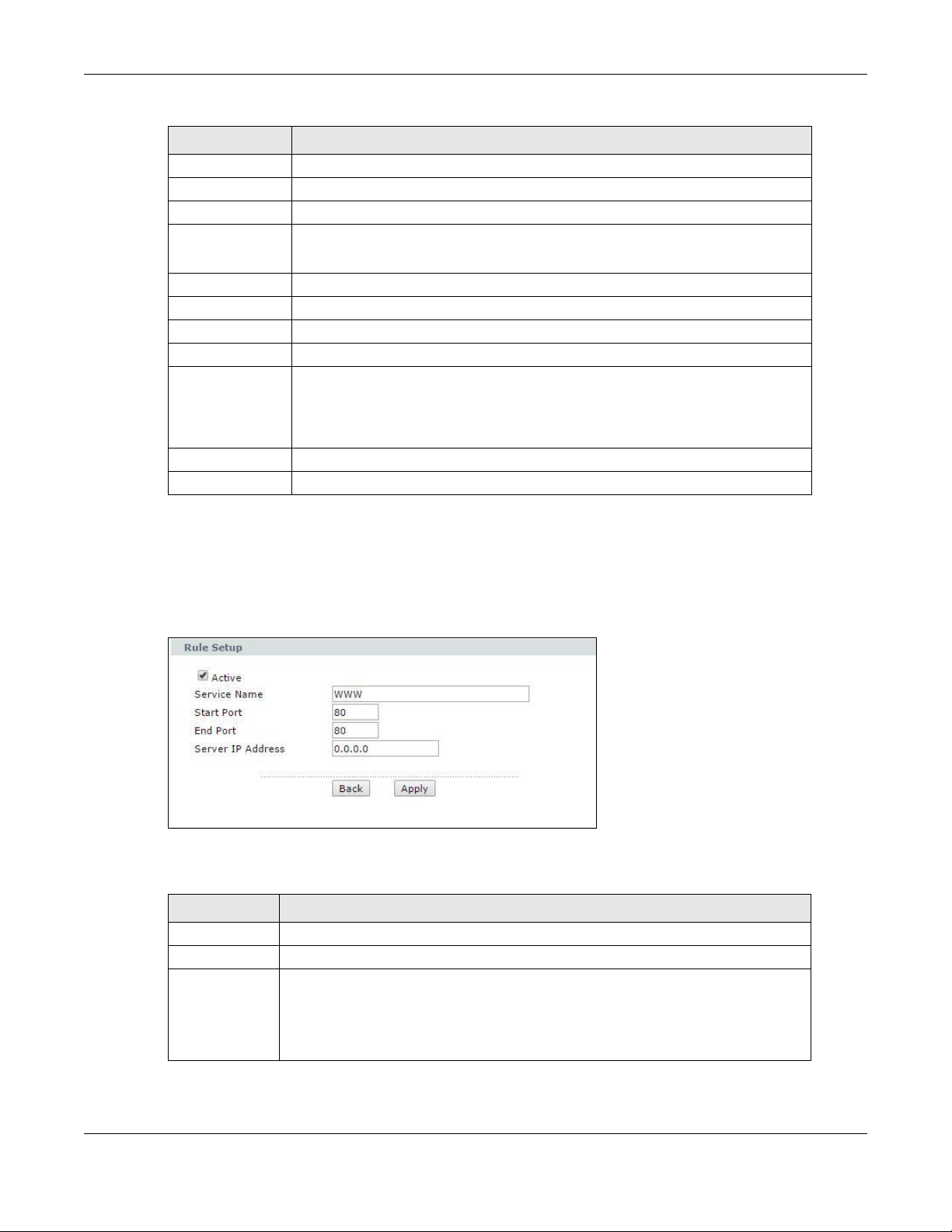
Chapter 9 Network Address Translation (NAT)
Table 28 Network > NAT > Port Forwarding
LABEL DESCRIPTION
Server IP Address Enter the IP address of the server for the specified service.
Add Click this button to add a rule to the table below.
# This is the rule index number (read-only).
Active This field indicates whether the rule is active or not.
Clear the check box to disable the rule. Select the check box to enable it.
Service Name This is a service’s name.
Start Port This is the first port number that identifies a service.
End Port This is the last port number that identifies a service.
Server IP Address This is the server’s IP address.
Modify Click the edit icon to go to the screen where you can edit the port forwarding
Apply Click this to save your changes.
Cancel Click this to restore your previously saved settings.
rule.
Click the delete icon to delete an existing port forwarding rule. Note that
subsequent address mapping rules move up by one when you take this action.
9.3.2 The Port Forwarding Rule Edit Screen
Use this screen to edit a port forwarding rule. Click the rule’s edit icon in the Port Forwarding
screen to display the screen shown next.
Figure 53 Network > NAT > Port Forwarding: Edit
The following table describes the fields in this screen.
Table 29 Network > NAT > Port Forwarding: Edit
LABEL DESCRIPTION
Active Click this check box to enable the rule.
Service Name Enter a name to identify this port-forwarding rule.
Start Port Enter a port number in this field.
To forward only one port, enter the port number again in the End Port field.
To forward a series of ports, enter the start port number here and the end port
number in the End Port field.
P-79X Series User’s Guide
91
Page 92

Chapter 9 Network Address Translation (NAT)
Table 29 Network > NAT > Port Forwarding: Edit (continued)
LABEL DESCRIPTION
End Port Enter a port number in this field.
To forward only one port, enter the port number again in the Start Port field
above and then enter it again in this field.
T o forw ard a series of ports, enter the last port number in a series that begins with
the port number in the Start Port field above.
Server IP
Address
Back Click this to return to the previous screen without saving .
Apply Click this to save your changes.
Enter the inside IP address of the server here.
9.4 The Address Mapping Screen
Note: The Address Mapping screen is available only when you select Full Feature in
the NAT > General screen.
Ordering your rules is important because the P-79X applies the rules in the order that you specify.
When a rule matches the current packet, the P-79X takes the corresponding action and the
remaining rules are ignored. To change your P-79X’s address mapping settings, click Network >
NAT > Address Mapping to open the following screen.
Figure 54 Network > NAT > Address Mapping
The following table describes the fields in this screen.
Table 30 Network > NAT > Address Mapping
LABEL DESCRIPTION
# This is the rule index number.
Local Start IP This is the starting Inside Local IP Address (ILA). Local IP addresses are N/A for
Server port mapping.
Local End IP This is the end Inside Local IP Address (ILA). If the rule is for all local IP addresses,
then this field displays 0.0.0.0 as the Local Start IP address and
255.255.255.255 as the Local End IP address. This field is N/A for One-to-one
and Server mapping types.
P-79X Series User’s Guide
92
Page 93

Chapter 9 Network Address Translation (NAT)
Table 30 Network > NAT > Address Mapping (continued)
LABEL DESCRIPTION
Global Start IP This is the starting Inside Global IP Address (IGA). Enter 0.0.0.0 here if you have a
dynamic IP address from your ISP. You can only do this for Many-to-One and
Server mapping types.
Global End IP This is the ending Inside Global IP Address (IGA). This field is N/A for One-to-
Type 1-1: One-to-one mode maps one local IP address to one global IP address. Note
Modify Click the edit icon to go to the screen where you can edit the address mapping
one, Many-to-One and Server mapping types.
that port numbers do not change for the One-to-one NAT mapping type.
M-1: Many-to-One mode maps multiple local IP addresses to one global IP
address. This is equivalent to SUA (i.e., PAT, port address translation), ZyXEL's
Single User Account feature that previous ZyXEL routers supported only.
M-M Ov (Overload): Many-to-Many Overload mode maps multiple local IP
addresses to shared global IP addresses.
MM No (No Overload): Many-to-Many No Overload mode maps each local IP
address to unique global IP addresses.
Server: This type allows you to specify inside servers of different services behind
the NAT to be accessible to the outside world.
rule.
Click the delete icon to delete an existing address mapping rule. Note that
subsequent address mapping rules move up by one when you take this action.
9.4.1 The Address Mapping Rule Edit Screen
Use this screen to edit an address mapping rule. Click the rule’s edit icon in the Address Mapping
screen to display the screen shown next.
Figure 55 Network > NAT > Address Mapping: Edit
P-79X Series User’s Guide
93
Page 94

Chapter 9 Network Address Translation (NAT)
The following table describes the fields in this screen.
Table 31 Network > NAT > Address Mapping: Edit
LABEL DESCRIPTION
Type Choose the port mapping type from one of the following.
One-to-One: One-to-One mode maps one local IP address to one global IP
address. Note that port numbers do not change for One-to-one NAT mapping type.
Many-to-One: Many-to-One mode maps multiple local IP addresses to one global
IP address. This is equivalent to SUA (i.e., PAT, port address translation), ZyXEL's
Single User Account feature that previous ZyXEL routers supported only.
Many-to-Many Overload: Many-to-Many Overload mode maps multiple local IP
addresses to shared global IP addresses.
Many-to-Many No Overload: Many-to-Many No Overload mode maps each local
IP address to unique global IP addresses.
Server: This type allows you to specify inside servers of different services behind
the NAT to be accessible to the outside world.
Local Start IP This is the starting local IP address (ILA). Local IP addresses are N/A for Server
port mapping.
Local End IP This is the end local IP address (ILA). If your rule is for all local IP addresses, then
enter 0.0.0.0 as the Local Start IP address and 255.255.255.255 as the Local
End IP address.
This field is N/A for One-to-One and Server mapping types.
Global Start IP This is the starting global IP address (IGA). Enter 0.0.0.0 here if you have a
dynamic IP address from your ISP.
Global End IP This is the ending global IP address (IGA). This field is N/A for One-to-One,
Server Mapping
Set
Edit Details Click this link to go to the Port Forwarding screen to edit a port forwarding set
Back Click this to return to the previous screen without saving .
Apply Click this to save your changes.
Cancel Click this to restore your previously saved settings.
Many-to-One and Server mapping types.
Only available when Type is set to Server.
Select a number from the drop-down menu to choose a port forwarding set.
that you have selected in the Server Mapping Set field.
9.5 The ALG Screen
Some NAT routers may include a SIP Application Layer Gateway (ALG). A SIP ALG allows SIP calls
to pass through NAT by examining and translating IP addresses embedded in the data stream.
When the P-79X registers with the SIP register server, the SIP ALG translates the P-79X’s private IP
address inside the SIP data stream to a public IP address. You do not need to use STUN or an
outbound proxy if your P-79X is behind a SIP ALG.
Use this screen to enable and disable the SIP (VoIP) ALG in the P-79X. To access this screen, click
Network > NAT > ALG.
P-79X Series User’s Guide
94
Page 95

Chapter 9 Network Address Translation (NAT)
Figure 56 Network > NAT > ALG
The following table describes the fields in this screen.
Table 32 Network > NAT > ALG
LABEL DESCRIPTION
Enable SIP ALG Select this to change the private ports or IP in SIP messages so that the VoIP
client behind the P-79X can be found in RTP traffic.
Apply Click this to save your changes.
Reset Click this to restore your previously saved settings.
9.6 NAT Technical Reference
This chapter contains more information regarding NAT.
9.6.1 NAT Definitions
Inside/outside denotes where a host is located relative to the P-79X, for example, the computers of
your subscribers are the inside hosts, while the web servers on the Internet are the outside hosts.
Global/local denotes the IP address of a host in a packet as the packet traverses a router, for
example, the local address refers to the IP address of a host when the packet is in the local
network, while the global address refers to the IP address of the host when the same packet is
traveling in the WAN side.
Note that inside/outside refers to the location of a host, while global/local refers to the IP address
of a host used in a packet. Thus, an inside local address (ILA) is the IP address of an inside host in
a packet when the packet is still in the local network, while an inside global address (IGA) is the IP
address of the same inside host when the packet is on the WAN side. The following table
summarizes this information.
Table 33 NAT Definitions
ITEM DESCRIPTION
Inside This refers to the host on the LAN.
Outside This refers to the host on the WAN.
Local This refers to the packet address (source or destination) as the packet travels on the
LAN.
Global This refers to the packet address (source or destination) as the packet travels on the
WAN.
NAT never changes the IP address (either local or global) of an outside host.
P-79X Series User’s Guide
95
Page 96

9.6.2 What NAT Does
192.168.1.13
192.168.1.10
192.168.1.11
192.168.1.12
SA
192.168.1.10
SA
IGA1
Inside Local
IP Address
192.168.1.10
192.168.1.11
192.168.1.12
192.168.1.13
Inside Global
IP Address
IGA 1
IGA 2
IGA 3
IGA 4
NAT Table
WAN
LAN
Inside Local
Address (ILA)
Inside Global
Address (IGA)
In the simplest form, NAT changes the source IP address in a packet received from a subscriber
(the inside local address) to another (the inside global address) before forwarding the packet to the
WAN side. When the response comes back, NAT translates the destination address (the inside
global address) back to the inside local address before forwarding it to the original inside host. Note
that the IP address (either local or global) of an outside host is never changed.
The global IP addresses for the inside hosts can be either static or dynamically assigned by the ISP .
In addition, you can designate servers, for example, a web server and a telnet server, on your local
network and make them accessible to the outside world. If you do not define any servers (for Many to-One and Many-to-Many Overload mapping – see Table 34 on page 98), NAT offers the additional
benefit of firewall protection. With no servers defined, your P-79X filters out all incoming inquiries,
thus preventing intruders from probing your network. For more information on IP address
translation, refer to RFC 1631, The IP Network Address Translator (NAT).
9.6.3 How NAT Works
Each packet has two addresses – a source address and a destination address. For outgoing packets,
the ILA (Inside Local Address) is the source address on the LAN, and the IGA (Inside Global
Address) is the source address on the WAN. For incoming packets, the ILA is the destination
address on the LAN, and the IGA is the destination address on the WAN. NAT maps private (local)
IP addresses to globally unique ones required for communication with hosts on other networks. It
replaces the original IP source address (and TCP or UDP source port numbers for Many-to-One and
Many-to-Many Overload NAT mapping) in each packet and then forwards it to the Internet. The P79X keeps track of the original addresses and port numbers so incoming reply packets can have
their original values restored. The following figure illustrates this.
Chapter 9 Network Address Translation (NAT)
9.6.4 NAT Application
Figure 57 How NAT Works
The following figure illustrates a possible NAT application, where three inside LANs (logical LANs
using IP alias) behind the P-79X can communicate with three distinct WAN networks.
P-79X Series User’s Guide
96
Page 97

Chapter 9 Network Address Translation (NAT)
Figure 58 NAT Application With IP Alias
9.6.5 NAT Mapping Types
NAT supports five types of IP/port mapping. They are:
• One to One: In One-to-One mode, the P-79X maps one local IP address to one global IP
address.
• Many to One: In Many-to-One mode, the P-79X maps multiple local IP addresses to one global
IP address. This is equivalent to SUA (for instance, PAT, port address translation), ZyXEL ’s Single
User Account feature that previous ZyXEL routers supported (the SUA Only option in today’s
routers).
• Many to Many Overload: In Many-to-Many Overload mode, the P-79X maps the multiple local
IP addresses to shared global IP addresses.
• Many-to-Many No Overload:
IP address to a unique global IP address.
• Server: This type allows you to specify inside servers of different services behind the NAT to be
accessible to the outside world.
Port numbers do NOT change for One-to-One and Many-to-Many No Overload NAT mapping
types.
In Many-to-Many No Overload mode, the P-79X maps each local
P-79X Series User’s Guide
97
Page 98

Chapter 9 Network Address Translation (NAT)
The following table summarizes these types.
Table 34 NAT Mapping Types
TYPE IP MAPPING
One-to-One ILA1 IGA1
Many-to-One (SUA/PAT) ILA1 IGA1
ILA2 IGA1
…
Many-to-Many Overload ILA1 IGA1
ILA2 IGA2
ILA3 IGA1
ILA4 IGA2
…
Many-to-Many No Overload ILA1 IGA1
ILA2 IGA2
ILA3 IGA3
…
Server Server 1 IP IGA1
Server 2 IP IGA1
Server 3 IP IGA1
P-79X Series User’s Guide
98
Page 99

10.1 Overview
WAN
LAN
3
4
1
2
A
This chapter shows you how to enable and configure the P-79X firewall. Use these screens to
enable and configure the firewall that protects your P-79X and network from attacks by hackers on
the Internet and control access to it. By default the firewall:
• allows traffic that originates from your LAN computers to go to all other networks.
• blocks traffic that originates on other networks from going to the LAN.
The following figure illustrates the default firewall action. User A can initiate an IM (Instant
Messaging) session from the LAN to the WAN (1). Return traffic for this session is also allowed (2).
However other traffic initiated from the WAN is blocked (3 and 4).
Figure 59 Default Firewall Action
CHAPTER 10
Firewalls
10.1.1 What You Can Do in the Firewall Screens
•Use the General screen (Section 10.2 on page 103) to enable firewall on the P-79X, and set the
default action that the firewall takes on packets that do not match any of the firewall rules.
•Use the Rules screen (Section 10.3 on page 104) to view the configured firewall rules and add,
edit or remove a firewall rule.
•Use the Threshold screen (Section 10.4 on page 107) to set the thresholds that the P-79X uses
to determine when to start dropping sessions that do not become fully established (half-open
sessions).
P-79X Series User’s Guide
99
Page 100

Chapter 10 Firewalls
10.1.2 What You Need to Know About Firewall
DoS
Denials of Service (DoS) attacks are aimed at devices and networks with a connection to the
Internet. Their goal is not to steal information, but to disable a device or network so users no longer
have access to network resources. The ZyXEL Device is pre-configured to automatically detect and
thwart all known DoS attacks.
Anti-Probing
If an outside user attempts to probe an unsupported port on your P-79X, an ICMP response packet
is automatically returned. This allows the outside user to know the P-79X exists. The P-79X
supports anti-probing, which prevents the ICMP response packet from being sent. This keeps
outsiders from discovering your P-79X when unsupported ports are probed.
ICMP
Internet Control Message Protocol (ICMP) is a message control and error-reporting protocol
between a host server and a gateway to the Internet. ICMP uses Internet Protocol (IP) datagrams,
but the messages are processed by the TCP/IP software and directly apparent to the application
user.
DoS Thresholds
For DoS attacks, the P-79X uses thresholds to determine when to drop sessions that do not become
fully established. These thresholds apply globally to all sessions. You can use the default threshold
values, or you can change them to values more suitable to your security requirements.
Finding Out More
•See Section 10.1.3 on page 100 for an example of setting up a firewall.
•See Section 10.5 on page 110 for advanced technical information on firewall.
10.1.3 Firewall Rule Setup Example
The following Internet firewall rule example allows a hypothetical “MyService” connection from the
Internet.
1 Click Security > Firewall > Rules.
2 Select WAN to LAN in the Packet Direction field.
P-79X Series User’s Guide
100
 Loading...