

Page 1
P-793H v2
G.SHDSL.bis Bonded Broadband Gateway
Default Login Details
IP Address http://192.168.1.1
Admin
Password
User
Password
Firmware Version 3.70
Edition 1, 03/2010
www.zyxel.com
1234
user
www.zyxel.com
Copyright © 2010
ZyXEL Communications Corporation
Page 2

Page 3

About This User's Guide
About This User's Guide
Intended Audience
This manual is intended for people who want to configure the P-793H v2 using the
web configurator.
Tips for Reading User’s Guides On-Screen
When reading a ZyXEL User’s Guide On-Screen, keep the following in mind:
• If you don’t already have the latest version of Adobe Reader, you can download
it from http://www.adobe.com.
• Use the PDF’s bookmarks to quickly navigate to the areas that interest you.
Adobe Reader’s bookmarks pane opens by default in all ZyXEL User’s Guide
PDFs.
• If you know the page number or know vaguely which page-range you want to
view, you can enter a number in the toolbar in Reader, then press [ENTER] to
jump directly to that page.
• Type [CTRL]+[F] to open the Adobe Reader search utility and enter a word or
phrase. This can help you quickly pinpoint the information you require. You can
also enter text directly into the toolbar in Reader.
• To quickly move around within a page, press the [SPACE] bar. This turns your
cursor into a “hand” with which you can grab the page and move i t around freely
on your screen.
• Embedded hyperlinks are actually cross-references to related text. Click them to
jump to the corresponding section of the User’s Guide PDF.
Related Documentation
•Quick Start Guide
The Quick Start Guide is designed to help you get up and running right away. It
contains information on setting up your network and configuring for Internet
access.
• Support Disc
Refer to the included CD for support documents.
Documentation Feedback
Send your comments, questions or suggestions to: techwriters@zyxel.com.tw
Thank you!
P-793H v2 User’s Guide
3
Page 4
About This User's Guide
The Technical Writing Team, ZyXEL Communications Corp.,
6 Innovation Road II, Science-Based Industrial Park, Hsinchu, 30099, Taiwan.
Need More Help?
More help is available at www.zyx el.com.
• Download Library
Search for the latest product updates and documentation from this link. Read
the Tech Doc Overview to find out how to efficiently use the User Guide, Quick
Start Guide and Command Line Interface Reference Guide in order to better
understand how to use your product.
• Knowledge Base
If you have a specific question about your product, the answer may be here.
This is a collection of answers to previously asked questions about ZyXEL
products.
•Forum
This contains discussions on ZyXEL prod ucts. Learn from others who use ZyXEL
products and share your experiences as well.
Customer Support
Should problems arise that cannot be solved by the methods listed above, you
should conta ct your vendor. If you cannot con tact your vendor, then contact a
ZyXEL office for the region in which you bought the device.
See http://www.zyxel.com/web/contact_us.php for contact information. Please
have the following informatio n ready when you contact an office.
4
• Product model and serial number.
•Warranty Information.
• Date that you received your device.
• Brief description of the problem and the steps you took to solve it.
P-793H v2 User’s Guide
Page 5

About This User's Guide
Disclaimer
Graphics in this book may differ slightly from the product due to differences in
operating systems, operating system versions, or if you installed updated
firmware/software fo r y our dev ice. Ev ery effort has been made to ensur e that the
information in this manual is accurate.
P-793H v2 User’s Guide
5
Page 6

Document Conventions
Warnings and Notes
These are how warnings and notes are shown in this User’s Guide.
Warnings tell you about things that could harm you or your device.
Note: Notes tell you other important information (for example, other things you may
need to configure or helpful tips) or recommendations.
Syntax Conventions
• The P-793H v2 may be referred to as the “device”, the “system” or the “product”
in this User’s Guide.
• Product labels, screen names, field labels and field choices are all in bold font.
Document Conventions
• A key stroke is denoted by square brackets and uppercase text, for example,
[ENTER] means the “enter” or “return” key on you r keyboard.
• “Enter” means for you to type one or more characters and then press the
[ENTER] key. “Select” or “choose” means for you to use one of the predefined
choices.
• A right angle bracket (>) within a screen name denotes a mouse click. For
example, Maintenance > Log > Log Setting means you first click
Maintenance in the navigation panel, then the Log sub menu and finally the
Log Setting tab to get to that screen.
• Units of measurement may denote the “metric” value or the “scientific” value.
For example, “k” for kilo may denote “1000” or “1024”, “M” for mega may
denote “1000000” or “1048576” and so on.
• “e.g.,” is a shorthand for “for instance”, and “i.e.,” means “that is” or “in other
words”.
6
P-793H v2 User’s Guide
Page 7
Document Conventions
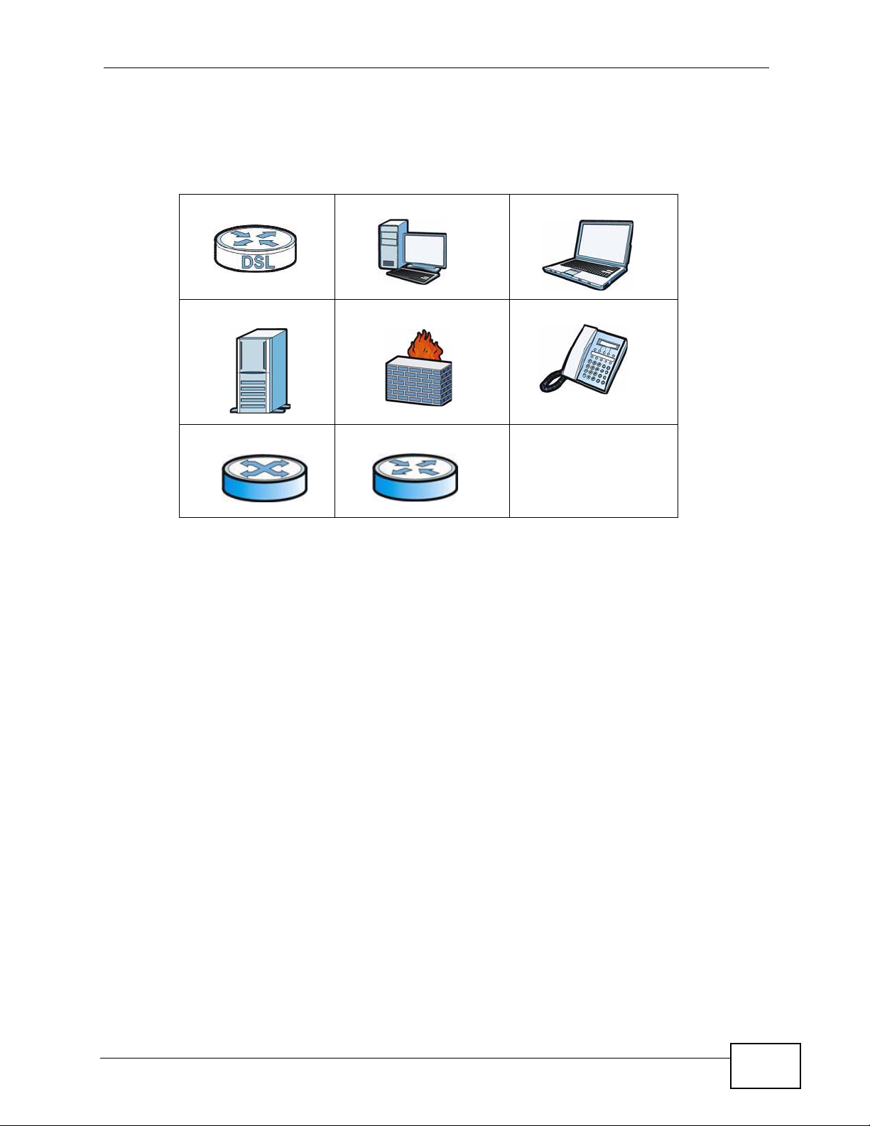
Icons Used in Figures
Figures in this User’s Guide may use the following generic icons. The P-793H v2
icon is not an exact representation of your device.
P-793H v2 Computer Notebook computer
Server Firewall Telephone
Switch Router
P-793H v2 User’s Guide
7
Page 8

Safety Warnings
• Do NOT use this product near water, for example, in a wet basement or near a swimming
pool.
• Do NOT expose your device to dampness, dust or corrosive liquids.
• Do NOT store things on the device.
• Do NOT install, use, or service this device during a thunderstorm. There is a remote risk
of electric shock from lightning.
• Connect ONLY suitable accessories to the device.
• Do NOT open the device or unit. Opening or removing covers can expose you to
dangerous high voltage points or other risks. ONLY qualified service personnel should
service or disassemble this device. Please contact your vendor for further information.
• Make sure to connect the cables to the correct ports.
• Place connecting cables carefully so that no one will step on them or stumble over them.
• Always disconnect all cables from this device before servicing or disassembling.
• Use ONLY an appropriate power adaptor or cord for your device.
• Connect the power adaptor or cord to the right supply voltage (for example, 110V AC in
North America or 230V AC in Europe).
• Do NOT allow anything to rest on the power adaptor or cord and do NOT place the
product where anyone can walk on the power adaptor or cord.
• Do NOT use the device if the power adaptor or cord is damaged as it might cause
electrocution.
• If the power adaptor or cord is damaged, remove it from the device and the power
source.
• Do NOT attempt to repair the power adaptor or cord. Contact your local vendor to order a
new one.
• Do not use the device outside, and make sure all the connections are indoors. There is a
remote risk of electric shock from lightning.
• Do NOT obstruct the device ventilation slots, as insufficient airflow may harm your
device.
• Use only No. 26 AWG (American Wire Gauge) or larger telecommunication line cord.
Safety Warnings
8
Your product is marked with this symbol, which is known as the WEEE mark. WEEE
stands for Waste Electronics and Electrical Equipment. It means that used electrical
and electronic products should not be mixed with general waste. Used electrical and
electronic equipment should be treated separately.
P-793H v2 User’s Guide
Page 9

Contents Overview
Contents Overview
User’s Guide ........................................................................................................ ...................35
Getting To Know Your P-793H v2 .............................................................................................. 37
Introducing the Web Configurator .............................................................................................. 43
Status Screens .......................................................................................................................... 51
Internet Setup Wizard................................................................................................................ 57
Tutorials ..................................................................................................................................... 67
Technical Reference ..............................................................................................................73
WAN Setup ...................................................................... ... ... .... ... ... .......................................... 75
LAN Setup ...............................................................................................................................101
Network Address Translation (NAT) .........................................................................................117
Firewalls .................................................................................................................................. 133
Content Filtering ...................................................................................................................... 155
VPN .........................................................................................................................................161
Certificates ................................... ....................... ....................... ...................... ........................ 193
Static Route ............................................................................................................................. 203
802.1Q/1P ............................................................................................................................... 207
Quality of Service (QoS) ........................... ... .... ... ... ... .... ... ... ... .... ... ... ........................................ 217
Dynamic DNS Setup ................................................................................................................ 235
Remote Management ..............................................................................................................239
Universal Plug-and-Play (UPnP) ............................................................................................. 251
System Settings ........... ............................................. .... ... ... ... .... .............................................. 263
Logs ....................................... .................................................... .............................................. 269
Tools ........................................................................................................................................ 283
Diagnostic .................................... ....................................................... ..................................... 297
Introducing the SMT ................................................................................................................ 301
General Setup ............................................. .... ... ... ... .... ... ... ... .... .............................................. 307
WAN Setup ...................................................................... ... ... .... ... ... .........................................311
LAN Setup ...............................................................................................................................317
Internet Access Setup ............................................................................................................. 321
Remote Node Setup ................................................................................................................ 325
Static Route Setup ...................................................................................................................335
NAT Setup ............................................................................................................................... 339
..................................... .................... ................ ................... ................... ..................................353
Firewall Setup ..........................................................................................................................355
Filter Configuration .................................................................................................................. 357
System Password ........................ .... ... ............................................. ... ... .... ... ... ........................ 373
System Information & Diagnosis ............................................................................................. 375
P-793H v2 User’s Guide
9
Page 10

Contents Overview
Firmware and Configuration File Maintenance ........................................................................387
Menus 24.8 to 24.11 ........................ ... ... ... ... .... ... ... ... .............................................. ... ... ... ........ 403
Schedule Setup ..... ... ... ... .... ... ... ... .... ... ... ............................................. ... .... ... ... ... .... ... ... ... .........411
Troubleshooting ..................................................... .................................................................. 415
10
P-793H v2 User’s Guide
Page 11

Table of Contents
Table of Contents
About This User's Guide..........................................................................................................3
Document Conventions............................................................................................................6
Safety Warnings ........................................................................................................................8
Contents Overview ...................................................................................................................9
Table of Contents....................................................................................................................11
List of Figures.........................................................................................................................23
List of Tables...........................................................................................................................31
Part I: User’s Guide................................................................................ 35
Chapter 1
Getting To Know Your P-793H v2 ..........................................................................................37
1.1 Overview ............. ............................................. ... .... ... ... ... .................................................... 37
1.1.1 High-speed Internet Access with G.SHDSL ............................................................... 37
1.1.2 High-speed Point-to-point Connections ........................................... ... .... ... ... ... ... .......38
1.1.3 High-speed Point-to-2points Connections .................................................................. 38
1.2 Ways to Manage the P-793H v2 ................................................... ... .... ... ... ... ....................... 39
1.3 Good Habits for Managing the P-793H v2 ........................................................................... 40
1.4 LEDs ......................... .............................................. ... ... ....................................................... 40
1.5 The RESET Button ....................................................................... ... .... ... ... ... .... ................... 41
1.5.1 Using the RESET Button ............................................................................................ 41
Chapter 2
Introducing the Web Configurator ........................................................................................43
2.1 Web Configurator Overview ................................................................................................. 43
2.2 Accessing the Web Configurator ......................................................................................... 43
2.3 Web Configurator Main Screen ........................................................................................... 45
2.3.1 Title Bar .................................. ............................................. ... .... ................................ 46
2.3.2 Navigation Panel ....... ... .... ... ... ... ... .... ... ....................................................................... 46
2.3.3 Main Window .......................... ... ............................................. .... ... ... ... .... ... ................49
2.3.4 Status Bar ............................................... ... .............................................. ... ................ 49
Chapter 3
Status Screens........................................................................................................................51
P-793H v2 User’s Guide
11
Page 12

Table of Contents
3.1 Overview ............. ............................................. ... .... ... ... ... .................................................... 51
3.2 The Status Screen ............................................................................................................... 51
3.3 Client List ......................... ... ... .............................................. ... ... .......................................... 54
3.4 Status: VPN Status .............................................................................................................. 54
3.5 Any IP Table ................ ... ... ... .... ... ... ............................................. ... .... ... ... ... ....................... 54
3.6 Packet Statistics .................................................................. ... ... ... ... .... ... ... .......................... 55
Chapter 4
Internet Setup Wizard.............................................................................................................57
4.1 Overview ............. ............................................. ... .... ... ... ... .................................................... 57
4.2 Internet Access Wizard Setup ............................................................................................. 57
4.2.1 Manual Configuration ....... ... ... ... ... .... ... ... ... .... ................................................ ............. 60
Chapter 5
Tutorials...................................................................................................................................67
5.1 Overview ............. ............................................. ... .... ... ... ... .................................................... 67
5.2 Configuring Point-to-point Connection .......................................... ... .... ... ... ... .... ... ... ............. 67
5.2.1 Set Up the Server ....................................................................................................... 68
5.2.2 Set Up the Client ........................................................................................................69
5.2.3 Connect the P-793H v2s ............................................................................................ 69
5.3 Configuring a Point-to-2points Connection .......................................................................... 70
5.3.1 Set up the Server ................ ... ... ... .... ... ... ... .... ... ............................................. ... ... .... ... 70
5.3.2 Set up the Clients ................................... ... .... ... ... ... .... ... ... ..........................................71
5.3.3 Connect the P-793H v2s ............................................................................................ 72
Part II: Technical Reference .................................................................. 73
Chapter 6
WAN Setup...............................................................................................................................75
6.1 Overview ............. ............................................. ... .... ... ... ... .................................................... 75
6.1.1 What Yo u Can Do in the WAN Screens ..................................................................... 75
6.1.2 What You Need to Know About WAN ........................................................................ 76
6.1.3 Before You Begin ... ... ... .............................................. ... ... ... ... .... ... ... ... ....................... 77
6.2 The Internet Access Setup Screen ...................................................................................... 78
6.2.1 2Wire-2Line Service Mode ............................... ... ... .... ... ... ... ... .... ................................ 82
6.2.2 Advanced Internet Access Setup ............................................................................... 83
6.3 The More Connections Screen .................................. ... ... ................................................. ... 86
6.3.1 More Connections Edit .............................. .... ... ... ... .... ... ............................................. 87
6.3.2 Configuring More Connections Advanced Setup ... .... ... ... ... ... .... ... ... ... .... ... ... ... ... .... ... 90
6.4 The WAN Backup Setup Screen .... ... ... .... ................................................ ... .... ... ... ... .......... 92
6.5 WAN Technical Reference ................................................................................................... 93
12
P-793H v2 User’s Guide
Page 13

Table of Contents
6.5.1 Encapsulation ................... ... ... ... ... .............................................. ... ... ... .... ... ................ 93
6.5.2 Multiplexing ......... ... ... ............................................. .... ... ... ... ... .... ................................ 95
6.5.3 VPI and VCI ........................................................ ... .... ... ... .......................................... 95
6.5.4 IP Address Assignment .......................................... .... ... ............................................. 95
6.5.5 Nailed-Up Connection (PPP) ..................................................................................... 96
6.5.6 NAT .............................................. .............................................. ... ............................. 96
6.6 Metric ............................ ... ... ... .............................................. ... ... .......................................... 96
6.7 Traffic Redirect .................................................................................................................... 97
6.8 Traffic Shaping ....................................... .... ... ... ... .... ... ... ... .................................................... 98
6.8.1 ATM Traffic Classes ...................................................................................................99
Chapter 7
LAN Setup..............................................................................................................................101
7.1 Overview ............. ............................................. ... .... ... ... ... .................................................. 101
7.1.1 What Yo u Can Do in the LAN Screens ..................................................................... 101
7.1.2 What You Need To Know About LAN ............................................... ... .... ... ... ... ... .....102
7.1.3 Before You Begin ... ... ... .... ............................................. ... ... ... .... ... ... ... .... ... .............. 103
7.2 The IP Screen .................. ... ... .... ............................................. ... ... ... .... ... ... ... .... ... ..............103
7.2.1 The Advanced LAN IP Setup Screen ....................................................................... 104
7.3 The DHCP Setup Screen .................................................................................................. 106
7.4 The Client List Screen ....................................................................................................... 108
7.5 The IP Alias Screen ............................... .... ... ... ... .... ... ... ... .... ... ... ... ... .................................. 109
7.5.1 Configuring the LAN IP Alias Screen ........................................................................110
7.6 LAN Technic al Reference ... ............................................. .... ... ... ... ... .... ... ... ... ......................111
7.6.1 LANs, WANs and the ZyXEL Device .........................................................................111
7.6.2 DHCP Setup ..................... ... ... ... ... .... ... ... ... .............................................. ... ... ... ... .... ..112
7.6.3 DNS Server Addresses ....................................... ............................................. ... .... ..112
7.6.4 LAN TCP/IP .................. .... ... ... ............................................. ... .... ... ............................113
7.6.5 RIP Setup .................................. ... .... ... ... ... .... ... ... ............................................. ... ......114
7.6.6 Multicast . ... ... ............................................. .... ... ............................................. ... ... ......114
Chapter 8
Network Address Translation (NAT)....................................................................................117
8.1 Overview ............. ............................................. ... .... ... ... ... ...................................................117
8.1.1 What You Can Do in the NAT Screens ......................................................................1 17
8.1.2 What You Need To Know About NAT ............................... ... ... .... ... ... ... .... ... ... ... ... .... ..117
8.2 The NAT General Setup Screen .........................................................................................119
8.3 The Port Forwarding Screen ............................................................................................. 120
8.3.1 Configuring the Port Forwarding Screen ............................. ..................................... 121
8.3.2 The Port Forwarding Rule Edit Screen .................................................................... 122
8.4 The Address Mapping Screen ........................................................................................... 123
8.4.1 The Address Mapping Rule Edit Screen ..................................................................125
8.5 The ALG Screen .............................. ... ... .... ... ... ... .... ... ... ............................................. ... ..... 127
P-793H v2 User’s Guide
13
Page 14

Table of Contents
8.6 NAT Technical Reference .................................................................................................. 127
8.6.1 NAT Definitions ......... ... .... ............................................. ... ... ... .... ... ........................... 127
8.6.2 What NAT Does ........... .... ............................................. ... ... ... .... ... ........................... 128
8.6.3 How NAT Works .......................................................................................................129
8.6.4 NAT Application ...................................................... .... ... ... ... ..................................... 130
8.6.5 NAT Mapping Types ..... .... ... ... ............................................. ... .... ... ... ... ..................... 130
Chapter 9
Firewalls.................................................................................................................................133
9.1 Overview ............. ............................................. ... .... ... ... ... .................................................. 133
9.1.1 What You Can Do in the Firewall Screens ............................................................... 133
9.1.2 What You Need to Know About Firewall ... .... ... ... ... .... ... ... ... ... .... ... ... ... .... ... .............. 134
9.1.3 Firewall Rule Setup Example .... ... .... ... ... ... .... ... ... ... ................................................. . 135
9.2 The Firewall General Screen ............................................................................................. 138
9.3 The Firewall Rule Screen .................................................................................................. 140
9.3.1 Configuring Firewall Rules .............. ........................................................................ 142
9.3.2 Customized Services ..............................................................................................144
9.3.3 Configuring a Customized Service ......................................................................... 145
9.4 The Firewall Threshold Screen .......................................................................................... 145
9.4.1 Threshold Values ......... .... ... ... ... ............................................. .... ... ... ... .... ................. 146
9.4.2 Configuring Firewall Thresholds ............. .................................................................. 147
9.5 Firewall Technical Reference ........................... ... .... ... ... ................................................ .... . 149
9.5.1 Firewall Rules Overview ............... .... ... ............................................. ... .... ... ... ... ... .... . 149
9.5.2 Guidelines For Enhancing Security With Your Firewall ............................................150
9.5.3 Security Considerations ...... ... ... ... .... ... ... ... .... ............................................. ... ... ... .... . 151
9.5.4 Triangle Route ..................... ... ... ... .... ... ... ............................................. .... ... ... ... ... .....151
Chapter 10
Content Filtering...................................................................................................................155
10.1 Overview ......................................................................................................................... 155
10.1.1 What You Can Do in the Content Filter Screens ......................... ........................... 155
10.1.2 What You Need to Know About Content Filtering .................................................. 155
10.1.3 Before You Begin ................................................................................................... 155
10.1.4 Content Filtering Example ...................................................................................... 156
10.2 The Keyword Screen ...................................................................................................... 158
10.3 The Schedule Screen ..................................................................................................... 159
10.4 The Trusted Screen ........................................................................................................ 160
Chapter 11
VPN.........................................................................................................................................161
11.1 Overview .......................................................................................................................... 161
11.1.1 What You Can Do in the VPN Screens .................................................................. 161
11.1.2 What You Need to Know About IPSec VPN ........................................................... 162
14
P-793H v2 User’s Guide
Page 15

Table of Contents
11.1.3 Before You Begin .................................................................................................... 163
11.2 VPN Setup Screen .......................................................................................................... 163
11.3 The VPN Edit Screen ......................................................................................................166
11.4 Configuring Advanced IKE Settings ................................................................................171
11.5 Manual Key Setup ............................................................................................................ 173
11.5.1 Security Parameter Index (SPI) ............................................................................. 174
11.6 Configuring Manual Key .................................................................................................. 174
11.7 Viewing SA Monitor ......................................................................................................... 177
11.8 Configuring VPN Global Setting ...................................................................................... 179
11.9 IPSec VPN Technical Reference .....................................................................................179
11.9.1 IPSec Architecture ..................................................................................................180
11.9.2 IPSec and NAT .......................................................................................................180
11.9.3 VPN, NAT, and NAT Traversal ................................................................................ 181
11.9.4 Encapsulation ......................................................................................................... 183
11.9.5 IKE Phases ............................................................................................................184
11.9.6 Negotiation Mode ................................................................................................... 185
11.9.7 Keep Alive ..............................................................................................................185
11.9.8 Remote DNS Server ...............................................................................................185
11.9.9 ID Type and Content .............................................................................................. 186
11.9.10 Pre-Shared Key ........................ .... ... ... ... .... ... ... ... .... ... ........................................... 188
11.9.11 Diffie-Hellman (DH) Key Groups ........................................................................... 188
11.9.12 Telecommuter VPN/IPSec Examples ................................................................... 188
Chapter 12
Certificates ............................................................................................................................193
12.1 Overview ......................................................................................................................... 193
12.1.1 What You Need to Know About Certificates ........................................................... 193
12.1.2 Verifying a Certificate ............................................................................................. 194
12.2 The Trusted CAs Screen ................................................................................................. 195
12.2.1 Trusted CA Import ................................................................................................. 197
12.2.2 Trusted CA Details .................................................................................................198
12.3 Certificates Technical Reference .....................................................................................200
12.3.1 Certificates Overview ............................................................................................. 200
12.3.2 Private-Public Certificates ........................... ........................................................... 200
Chapter 13
Static Route...........................................................................................................................203
13.1 Overview ......................................................................................................................... 203
13.2 The Static Route Screen .................................................................................................. 204
13.2.1 Static Route Edit ................................................................................................... 205
Chapter 14
802.1Q/1P...............................................................................................................................207
P-793H v2 User’s Guide
15
Page 16

Table of Contents
14.1 Overview .......................................................................................................................... 207
14.1.1 What You Can Do in the 802.1Q/1P Screens ........................................................ 207
14.1.2 What You Need to Know About 802.1Q/1P ........................................................... 207
14.1.3 802.1Q/1P Example ............................................................................................... 209
14.2 The 802.1Q/1P Group Setting Screen .............................................................................213
14.2.1 Editing 802.1Q/1P Group Setting ................................... ... ... .................................. 214
14.3 The 802.1Q/1P Port Setting Screen ................................................................................ 215
Chapter 15
Quality of Service (QoS).......................................................................................................217
15.1 Overview .......................................................................................................................... 217
15.2 QoS Overview ................................................................................................................. 217
15.2.1 What You Can Do in the QoS Screens ..................................................................218
15.2.2 What You Need to Know About QoS ..................................................................... 218
15.2.3 QoS Class Setup Example ..................................................................................... 219
15.3 The QoS General Screen ............................................................................................... 223
15.4 The Class Setup Screen ................................................................................................. 224
15.4.1 The Class Configuration Screen ........................................................................... 226
15.5 The QoS Monitor Screen ................................................................................................ 230
15.6 QoS Technical Reference ................................................................................................ 231
15.6.1 IEEE 802.1Q Tag ................................................................................................... 231
15.6.2 IP Precedence ........................................................................................................ 231
15.6.3 DiffServ ................................................................................................................. 232
15.6.4 Automatic Priority Queue Assignment ................................................................... 232
Chapter 16
Dynamic DNS Setup .............................................................................................................235
16.1 Overview .......................................................................................................................... 235
16.1.1 What You Need To Know About DDNS .................................................................. 235
16.2 The Dynamic DNS Screen ................................................ ... ... ... ... .... ... ... ... .... ... ... ........... 2 36
Chapter 17
Remote Management............................................................................................................239
17.1 Overview .......................................................................................................................... 239
17.1.1 What You Can Do in the Remote Management Screens ....................................... 240
17.1.2 What You Need to Know About Remote Management .......................................... 240
17.2 The WWW Screen ........................................................................................................... 241
17.2.1 Configuring the WWW Screen ............................................................................... 241
17.3 The Telnet Screen ...........................................................................................................242
17.4 The FTP Screen ......... ... ... ... .... ... ... ... ... .... ................................................ ... ..................... 243
17.5 The SNMP Screen ...........................................................................................................244
17.5.1 Supported MIBs .....................................................................................................246
17.5.2 SNMP Traps ........................................................................................................... 246
16
P-793H v2 User’s Guide
Page 17

Table of Contents
17.5.3 Configuring SNMP .................................................................................................247
17.6 The DNS Screen .................................................... ... ... .... ... ... ... ... .................................. 248
17.7 The ICMP Screen ............................................................................................................ 249
Chapter 18
Universal Plug-and-Play (UPnP)..........................................................................................251
18.1 Overview .......................................................................................................................... 251
18.1.1 What You Can Do in the UPnP Screen .................................................................. 251
18.1.2 What You Need to Know About UPnP ................................................................... 251
18.2 The UPnP Screen ............................................................................................................253
18.3 Installing UPnP in Windows Example .............................................................................. 253
18.4 Using UPnP in Windows XP Example ............................................................................. 257
Chapter 19
System Settings....................................................................................................................263
19.1 Overview .......................................................................................................................... 263
19.1.1 What You Can Do in the System Settings Screens ................................................ 263
19.1.2 What You Need to Know About System Settings ..................... .............................. 263
19.2 The General Screen ........................................................................................................264
19.3 The Time Setting Screen ................................................................................................ 266
Chapter 20
Logs .......................................................................................................................................269
20.1 Overview .......................................................................................................................... 269
20.1.1 What You Can Do in the Log Screens .................................................................... 269
20.1.2 What You Need To Know About Logs .................................................................... 269
20.2 The View Log Screen ...................................................................................................... 270
20.3 The Log Settings Screen ..... .... ... ... ... ... ............................................................................ 271
20.4 SMTP Error Messages .................................................................................................... 273
20.4.1 Example E-mail Log ............................................................................................... 273
20.5 Log Descriptions .............................................................................................................. 274
Chapter 21
Tools.......................................................................................................................................283
21.1 Overview .......................................................................................................................... 283
21.1.1 What You Can Do in the Tool Screens ...................................................................283
21.1.2 What You Need To Know About Tools .................................................................... 284
21.1.3 Before You Begin ................................................................................................... 285
21.1.4 Tool Examples ........................................................................................................285
21.2 The Firmware Screen ...................................................................................................... 291
21.3 The Configuration Screen ................................................................................................ 293
21.4 The Restart Screen .........................................................................................................295
P-793H v2 User’s Guide
17
Page 18

Table of Contents
Chapter 22
Diagnostic..............................................................................................................................297
22.1 Overview .......................................................................................................................... 297
22.1.1 What You Can Do in the Diagnos tic Screens ........................................ ................. 297
22.2 The General Diagnostic Screen ...................................................................................... 297
22.3 The DSL Line Diagnostic Screen ....................................................................................298
Chapter 23
Introducing the SMT.............................................................................................................301
23.1 Accessing the SMT .................. ... ... ... ................................................. ... ........................... 301
23.2 SMT Menu Items .............................................................................................................302
23.3 Navigating the SMT Interface .......................................................................................... 305
Chapter 24
General Setup........................................................................................................................307
24.1 Configuring General Setup .............................................................................................. 307
24.1.1 Configuring Dynamic DNS ..................................................................................... 308
Chapter 25
WAN Setup.............................................................................................................................311
25.1 WAN Setup .......................................................................................................................311
25.1.1 2wire-2line Service Mode ..................................... .... ... ........................................... 313
25.2 Configuring Traffic Redirect ............................................................................................. 315
Chapter 26
LAN Setup..............................................................................................................................317
26.1 Accessing the LAN Menus ..............................................................................................317
26.2 LAN Port Filter Setup .......................................................................................................317
26.3 TCP/IP and DHCP Setup Menu ......................................................................................318
26.4 LAN IP Alias .................................................................................................................... 320
Chapter 27
Internet Access Setup..........................................................................................................321
27.1 Internet Access Setup .....................................................................................................321
Chapter 28
Remote Node Setup..............................................................................................................325
18
28.1 Introduction to Remote Node Setup ................................................................................ 325
28.2 Remote Node Setup ........................................................................................................ 325
28.3 Remote Node Profile .......................................................................................................326
28.4 Remote Node Network Layer Options ............................................................................. 328
28.5 Remote Node Filter ......................................................................................................... 330
28.6 Remote Node ATM Layer Options ........................... ................................ ........................ 332
P-793H v2 User’s Guide
Page 19

Table of Contents
28.7 Advance Setup Options ................................................................................................... 333
Chapter 29
Static Route Setup................................................................................................................335
29.1 IP Static Route Setup ...................................................................................................... 335
29.2 Bridge Static Route Setup ............................................................................................... 337
Chapter 30
NAT Setup..............................................................................................................................339
30.1 Using NAT ........................................................................................................................ 339
30.1.1 SUA (Single User Account) Versus NAT ................................................................ 339
30.1.2 Applying NAT ......................................................................................................... 340
30.2 NAT Setup .......................................................................................................................341
30.2.1 Address Mapping Sets ........................................................................................... 342
30.3 Configuring a Server behind NAT ........ .... ... ............................................. ... .... ... .............. 345
30.4 General NAT Examples ................................................................................................... 346
30.4.1 Internet Access Only .............................................................................................. 347
30.4.2 Example 2: Internet Access with a Default Server ...................................... ... ... .....348
30.4.3 Example 3: Multiple Public IP Addresses With Inside Servers .............................. 348
30.4.4 Example 4: NAT Unfriendly Application Programs ................................................. 352
................................................................................................................................................353
Chapter 31
Firewall Setup........................................................................................................................355
31.1 Using P-793H v2 SMT Menus ......................................................................................... 355
31.1.1 Activating the Firewall ............................................................................................ 355
Chapter 32
Filter Configuration...............................................................................................................357
32.1 Introduction to Filters ....................................................................................................... 357
32.1.1 The Filter Structure of the P-793H v2 ....................................................... ......... ..... 358
32.2 Configuring a Filter Set .................................................................................................... 360
32.2.1 Configuring a Filter Rule ........................................................................................ 362
32.2.2 Configuring a TCP/IP Filter Rule ............................................................................ 362
32.2.3 Configuring a Generic Filter Rule ........................................................................... 366
32.3 Example Filter .................................................................................................................. 367
32.4 Filter Types and NAT ........... .... ... ... ... ............................................................................... 369
32.5 Firewall Versus Filters ..................................................................................................... 370
32.6 Applying a Filter ............................................................................................................... 370
32.6.1 Applying LAN Filters ............................................................................................... 370
32.6.2 Applying Remote Node Filters ............................................................................... 371
Chapter 33
System Password.................................................................................................................373
P-793H v2 User’s Guide
19
Page 20

Table of Contents
Chapter 34
System Information & Diagnosis.........................................................................................375
34.1 Introduction to System Status .......................................................................................... 375
34.2 System Status .................................................................................................................. 375
34.3 System Information and Console Port Speed .................................... ... ........................... 377
34.3.1 System Information ................................................................................................ 378
34.3.2 Console Port Speed ............................................................................................... 379
34.4 Log and Trace .................................................................................................................. 379
34.4.1 Viewing Error Log ................................................................................................... 379
34.4.2 Syslog Logging ....................................................................................................... 381
34.5 Diagnostic ........................................................................................................................ 384
Chapter 35
Firmware and Configuration File Maintenance..................................................................387
35.1 Introduction ...................................................................................................................... 387
35.2 Filename Conventions ..................................................................................................... 387
35.3 Backup Configuration ......................................................................................................388
35.3.1 Backup Configuration ........................ ....................................... .............................. 389
35.3.2 Using the FTP Command from the Command Line .... ... ... ... .... ... ... ... .... ... .............. 3 89
35.3.3 Example of FTP Commands from the Command Line .......................................... 390
35.3.4 GUI-based FTP Clients .......................................................................................... 390
35.3.5 File Maintenance Over WAN .................................................................................. 390
35.3.6 Backup Configuration Using TFTP ......................................................................... 391
35.3.7 TFTP Command Example ...................................................................................... 391
35.3.8 GUI-based TFTP Clients ........................................................................................ 392
35.3.9 Backup Via Console Port ....................................................................................... 392
35.4 Restore Configuration ......................................................................................................393
35.4.1 Restore Using FTP ................................................................................................. 394
35.4.2 Restore Using FTP Session Example ....................................................................395
35.4.3 Restore Via Console Port ....................................................................................... 395
35.5 Uploading Firmware and Configuration Files .................................................................. 396
35.5.1 Firmware File Upload .............................. ............................................................... 396
35.5.2 Configuration File Upload ....................................................................................... 397
35.5.3 FTP File Upload Command from the DOS Prompt Example .................................398
35.5.4 FTP Session Example of Firmware File Upload .................................................... 398
35.5.5 TFTP File Upload ................................................................................................... 399
35.5.6 TFTP Upload Command Example ......................................................................... 399
35.5.7 Uploading Via Console Port ................................................................................... 400
35.5.8 Uploading Firmware File Via Console Port ............................................................400
35.5.9 Example Xmodem Firmware Upload Using HyperTerminal ..... ... ... ... .... ... ... ... ... .... . 401
35.5.10 Uploading Configuration File Via Console Port ................................... ... ... ... ... .... . 401
35.5.11 Example Xmodem Configuration Upload Using HyperTerminal ... ........................ 402
20
P-793H v2 User’s Guide
Page 21

Table of Contents
Chapter 36
Menus 24.8 to 24.11 ..............................................................................................................403
36.1 Command Interpreter Mode ............................................................................................ 403
36.1.1 Command Syntax ................................................................................................... 403
36.1.2 Command Usage ................................................................................................... 404
36.2 Call Control Support ........................................................................................................ 404
36.2.1 Budget Management .............................................................................................. 405
36.3 Time and Date Setting .......................................................... ...........................................406
36.4 Remote Management ...................................................................................................... 409
36.4.1 Remote Management Limitations .......................................................................... 409
Chapter 37
Schedule Setup.....................................................................................................................411
37.1 Schedule Set Overview ....................................................................................................411
37.2 Schedule Setup ................................................................................................................411
37.3 Schedule Set Setup ......................................................................................................... 412
Chapter 38
Troubleshooting....................................................................................................................415
38.1 Power, Hardware Connections, and LEDs .............................. ... ... .... .............................. 415
38.2 P-793H v2 Access and Login .......................................................................................... 416
38.3 Internet Access ................................................................................................................ 418
38.4 Network Connections ...................................................................................................... 419
Appendix A Product Specifications.......................................................................................421
Appendix B Wall-mounting Instructions................................................................................427
Appendix C Setting up Your Computer’s IP Address...........................................................429
Appendix D Pop-up Windows, JavaScripts and Java Permissions......................................453
Appendix E IP Addresses and Subnetting ...........................................................................463
Appendix F Services ............................................................................................................473
Appendix G Legal Information..............................................................................................477
Index.......................................................................................................................................481
P-793H v2 User’s Guide
21
Page 22

Table of Contents
22
P-793H v2 User’s Guide
Page 23

List of Figures
List of Figures
Figure 1 High-speed Internet Access with Your P-793H v2 .................................................................... 38
Figure 2 Point-to-point Connections with Your P-793H v2 ..................................................................... 38
Figure 3 Point-to-2points Connections with Your P-793H v2 .................................................................. 39
Figure 4 LEDs ......................................................................................................................................... 40
Figure 5 Login Screen ............................................................................................................................ 44
Figure 6 Change Password at Login ...................................................................................................... 44
Figure 7 Select a Mode .......................................................................................................................... 45
Figure 8 Main Screen ............................................................................................................................ 45
Figure 9 Status Screen ........................................................................................................................... 51
Figure 10 Any IP Table ........................................................................................................................... 54
Figure 11 Packet Statistics ..................................................................................................................... 55
Figure 12 Select a Mode ........................................................................................................................ 57
Figure 13 Wizard Welcome .................................................................................................................... 58
Figure 14 Auto Detection: No DSL Connection ...................................................................................... 58
Figure 15 Auto-Detection: PPPoE .......................................................................................................... 59
Figure 16 Auto Detection: Failed .............. .............................................................................................. 59
Figure 17 Internet Access Wizard Setup: ISP Parameters ................. .................... ................... ............. 60
Figure 18 Internet Connection with PPPoE ............................................................................................ 61
Figure 19 Internet Connection with RFC 1483 ...................................................................................... 62
Figure 20 Internet Connection with ENET ENCAP ................................................................................. 63
Figure 21 Internet Connection with PPPoA ............................................................................................ 64
Figure 22 Internet Access Setup Complete ..................... ... ... .... ... ... ... .... ................................................ 65
Figure 23 WAN > Internet Access Setup ................................................................................................ 68
Figure 24 WAN > Internet Access Setup ............................................................................................... 71
Figure 25 WAN > Internet Connection > Service Type of B ................................................................... 72
Figure 26 WAN > Internet Connection > Service Type of C ................................................................... 72
Figure 27 LAN and WAN ........................................................................................................................ 75
Figure 28 Network > WAN >Internet Access Setup ......................................... ... .... ... ... ... .... ................... 78
Figure 29 2wire-2line Service Mode ....................................................................................................... 82
Figure 30 Network > WAN > Internet Access Setup: Advanced Setup .................................................. 83
Figure 31 Network > WAN > More Connections .....................................................................................86
Figure 32 Network > WAN > More Connections: Edit ............................................................................ 87
Figure 33 Network > WAN > More Connections: Edit: Advanced Setup ......... ... .... ... ... ... .... ... ... ... ... .... ... 90
Figure 34 Network > Internet (WAN) > WAN Backup .............................................................................92
Figure 35 Traffic Redirect Example ........................................................................................................ 97
Figure 36 Traffic Redirect LAN Setup .....................................................................................................98
Figure 37 Example of Traffic Shaping ....................................................................................................99
Figure 38 Network > LAN > IP .............................................................................................................. 103
P-793H v2 User’s Guide
23
Page 24

List of Figures
Figure 39 Network > LAN > IP: Advanced Setup ................................................................................. 104
Figure 40 Network > LAN > DHCP Setup ............................................................................................ 106
Figure 41 Network > LAN > Client List ................................................................................................ 108
Figure 42 Physical Network & Partitioned Logical Networks ................................................................ 109
Figure 43 Network > LAN > IP Alias ......................................................................................................110
Figure 44 LAN and WAN IP Addresses .................................................................................................111
Figure 45 Network > NAT > General .. ... ... .... ... ... ... ................................................. ... ... ... .... ... ... ............119
Figure 46 Multiple Servers Behind NAT Example ................................................................................ 121
Figure 47 Network > NAT > Port Forwarding ....................................................................................... 121
Figure 48 Network > NAT > Port Forwarding: Edit .............................................................................. 122
Figure 49 Network > NAT > Address Mapping .....................................................................................124
Figure 50 Network > NAT > Address Mapping: Edit ............................................................................ 125
Figure 51 Network > NAT > ALG .......................................................................................................... 127
Figure 52 How NAT Works ................................................................................................................... 129
Figure 53 NAT Application With IP Alias .............................................................................................. 130
Figure 54 Default Firewall Action .................................. ................ ................ ................ ........................133
Figure 55 Security > Firewall > General ............................................................................................... 138
Figure 56 Security > Firewall > Rules ..................................................................................................140
Figure 57 Security > Firewall > Rules: Edit ..........................................................................................142
Figure 58 Security > Firewall > Rules: Edit: Edit Customized Services ............................................... 144
Figure 59 Security > Firewall > Rules: Edit: Edit Customized Services: Config ................................... 145
Figure 60 Three-Way Handshake ......................................................................................................... 146
Figure 61 Security > Firewall > Threshold ............................................................................................ 147
Figure 62 Ideal Firewall Setup .............................................................................................................. 151
Figure 63 “Triangle Route” Problem .....................................................................................................152
Figure 64 IP Alias ................................................................................................................................. 153
Figure 65 Security > Content Filtering > Keyword ................................................................................ 158
Figure 66 Security > Content Filter > Schedule .................................................................................... 159
Figure 67 Security > Content Filter: Trusted ......................................................................................... 160
Figure 68 VPN: Example ...................................................................................................................... 161
Figure 69 VPN: IKE SA and IPSec SA ................................................................................................ 162
Figure 70 IPSec Summary Fields .......................................... .... ... ... ... ..................................................163
Figure 71 Security > VPN > Setup ....................................................................................................... 164
Figure 72 Security > VPN > Setup > Edit ............................................................................................. 166
Figure 73 Security > VPN > Setup > Edit > Advanced Setup .............................................................. 171
Figure 74 Security > VPN > Setup > Manual Key ................................................................................ 174
Figure 75 Security > VPN > Monitor ..................................................................................................... 178
Figure 76 Security > VPN > Global Setting .......................................................................................... 179
Figure 77 IPSec Architecture ........................................................................ ... ... .... ... ... ... ..................... 180
Figure 78 NAT Router Between IPSec Routers ................................................................................... 182
Figure 79 Transport and Tunnel Mode IPSec Encapsulation ............................................................... 183
Figure 80 Two Phases to Set Up the IPSec SA ................................................................................... 184
Figure 81 VPN Host using Intranet DNS Server Example .................................................................... 186
24
P-793H v2 User’s Guide
Page 25

List of Figures
Figure 82 Telecommuters Sharing One VPN Rule Example ................................................................ 189
Figure 83 Telecommuters Using Unique VPN Rules Example ............................................................. 190
Figure 84 Certificates Example ............................................................................................................ 193
Figure 85 Remote Host Certificates ..................................................................................................... 194
Figure 86 Certificate Details ................................................................................................................ 195
Figure 87 Trusted CAs ..................................................... ............................................. ... ..................... 196
Figure 88 Trusted CA Import .... ... .............................................. ... ... ... .... ... ... ... ... .... .............................. 197
Figure 89 Trusted CA Details ...... .... ... ... ............................................. .... ... ... ... ... .... ... ... ... .... ................. 198
Figure 90 Example of Static Routing Topology ..................................................................................... 203
Figure 91 Advanced > Static Route ...................................................................................................... 204
Figure 92 Advanced > Static Route: Edit .............................................................................................. 205
Figure 93 802.1Q/1P ............................................................................................................................ 207
Figure 94 Advanced > 802.1Q/1P > Group Setting ..............................................................................213
Figure 95 Advanced > 802.1Q/1P > Group Setting > Edit .................................................................... 214
Figure 96 Advanced > 802.1Q/1P > Port Setting ................................................................................. 215
Figure 97 QoS Example ....................................................................................................................... 220
Figure 98 QoS Class Example: VoIP -1 ............................................................................................... 220
Figure 99 QoS Class Example: VoIP -2 ............................................................................................... 221
Figure 100 QoS Class Example: Boss -1 ............................................................................................. 221
Figure 101 QoS Class Example: Boss -2 ............................................................................................. 222
Figure 102 Advanced > QoS > General ............................................................................................... 223
Figure 103 Advanced > QoS > Class Setup ......................................................................................... 224
Figure 104 Advanced > QoS > Class Setup: Edit ................................................................................226
Figure 105 Advanced > QoS > Monitor ............................................................................................... 230
Figure 106 Advanced > Dynamic DNS .................................................................................................236
Figure 107 Remote Management From the WAN ................................................................................ 239
Figure 108 Advanced > Remote Management > WWW ......................................................................241
Figure 109 Advanced > Remote Management > Telnet ....................................................................... 242
Figure 110 Advanced > Remote Management > FTP ........................ ................................................. . 243
Figure 111 SNMP Management Model ................................................................................................. 245
Figure 112 Advanced > Remote Management > SNMP ........................ ... ... ... ... .... ... ... ... .... ................. 247
Figure 113 Advanced > Remote Management > DNS ........................................................... ... ... ... .... . 248
Figure 114 Advanced > Remote Management > ICMP ............. ... ... ... .... ... ... ... ..................................... 249
Figure 115 Advanced > UPnP > General ............................................................................................. 253
Figure 116 Maintenance > System > General ......................................................................................264
Figure 117 Maintenance > System > Time Setting ............................................................................... 266
Figure 118 Maintenance > Logs > View Log ........................................................................................ 270
Figure 119 Maintenance > Logs > Log Settings ...................................................................................271
Figure 120 E-mail Log Example ...........................................................................................................274
Figure 121 Restore Using FTP Session Example ................................................................................286
Figure 122 FTP Session Example of Firmware File Upload ................................................................. 287
Figure 123 FTP Session Example ........................................................................................................ 289
Figure 124 Maintenance > Tools > Firmware ....................................................................................... 291
P-793H v2 User’s Guide
25
Page 26

List of Figures
Figure 125 Firmware Upload In Progress ........................... .................... ................... ................... ........ 292
Figure 126 Network Temporarily Disconnected ....................................................................................292
Figure 127 Error Message .................................................................................................................... 292
Figure 128 Maintenance > Tools > Configuration .................................................................................293
Figure 129 Configuration Upload Successful ....................................................................................... 294
Figure 130 Network Temporarily Disconnected ....................................................................................294
Figure 131 Configuration Upload Error ................................................................................................. 294
Figure 132 Reset Warning Message ....................................................................................................295
Figure 133 Reset In Process Message ................................................................................................ 295
Figure 134 Maintenance > Tools >Restart ........................................................................................... 295
Figure 135 Maintenance > Diagnostic > General .................................................................................297
Figure 136 Maintenance > Diagnostic > DSL Line ............................................................................... 298
Figure 137 Login Screen ...................................................................................................................... 301
Figure 138 SMT Main Menu ................................................................................................................. 302
Figure 139 Menu 1: General Setup ...................................................................................................... 307
Figure 140 Menu 1.1: Configure Dynamic DNS ...................................................................................309
Figure 141 Menu 2: WAN Setup ............................................................................................................311
Figure 142 Menu 2: 2wire-2line Service Mode ................................ ... .... ... ... ........................................ 313
Figure 143 Menu 2.1: Traffic Redirect Setup ........................................................................................ 315
Figure 144 Menu 3: LAN Setup ............................................................................................................ 317
Figure 145 Menu 3.1: LAN Port Filter Setup ........................................................................................317
Figure 146 Menu 3.2: TCP/IP and DHCP Ethernet Setup .................................................................... 318
Figure 147 Menu 3.2.1: IP Alias Setup ................................................................................................. 320
Figure 148 Menu 4: Internet Access Setup .......................................................................................... 321
Figure 149 Menu 11: Remote Node Setup ............................ .... ............................................. ... ... ... ..... 325
Figure 150 Menu 11.1: Remote Node Profile (nodes 1-7) ...................... ... ... ... ... .... .............................. 326
Figure 151 Menu 11.3: Remote Node Network Layer Options ............................................................. 328
Figure 152 Menu 11.5: Remote Node Filter ....................... ... .... ... ... ... .... .............................................. 331
Figure 153 ...................................................................Menu 11.6: Remote Node ATM Layer Options 332
Figure 154 Menu 11.8: Advance Setup Options ................................................................................... 333
Figure 155 Menu 12.1: IP Static Route Setup ..................................................................................... 335
Figure 156 Menu 12.1.1: Edit IP Static Route ...................................................................................... 336
Figure 157 Menu 12.3: Bridge Static Route Setup ...............................................................................337
Figure 158 Menu 12.3.1: Edit Bridge Static Route ...............................................................................337
Figure 159 Menu 4: Applying NAT for Internet Access ....................................... .... ... ... ........................ 340
Figure 160 Menu 11.3: Applying NAT to the Remote Node .................................................................. 341
Figure 161 Menu 15: NAT Setup .......................................................................................................... 342
Figure 162 Menu 15.1: Address Mapping Sets ............................................ ... ... .... ... ... ........................ 342
Figure 163 Menu 15.1.1: Address Mapping Rules .................................................................... ... ... .... . 343
Figure 164 Menu 15.1.1.1: Address Mapping Rule .............................................................................. 344
Figure 165 Menu 15.2: NAT Server Sets ..............................................................................................345
Figure 166 Menu 15.2: NAT Server Setup ........................................................................................... 346
Figure 167 NAT Example 1 .................................................................................................................. 347
26
P-793H v2 User’s Guide
Page 27

List of Figures
Figure 168 Menu 4: Internet Access & NAT Example .......................................................................... 347
Figure 169 NAT Example 2 .................................................................................................................. 348
Figure 170 Menu 15.2: Specifying an Inside Server ............................................................................. 348
Figure 171 NAT Example 3 .................................................................................................................. 349
Figure 172 Example 3: Menu 11.3 ........................................................................................................ 350
Figure 173 Example 3: Menu 15.1.1.1 ................................................................................................. 351
Figure 174 Example 3: Final Menu 15.1.1 ............................................................................................ 351
Figure 175 Example 3: Menu 15.2 ....................................................................................................... 352
Figure 176 NAT Example 4 .................................................................................................................. 352
Figure 177 Example 4: Menu 15.1.1.1: Address Mapping Rule ........................................................... 353
Figure 178 Menu 21: Filter and Firewall Setup ......... .... ... ... ... .... ... ... ... .... ... ........................................... 355
Figure 179 Menu 21.2: Firewall Setup ................................ .................... ................... ...........................356
Figure 180 Outgoing Packet Filtering Process .....................................................................................357
Figure 181 Filter Rule Process ............................................................................................................. 359
Figure 182 Menu 21: Filter and Firewall Setup ......... .... ... ... ... .... ... ... ... .... ... ........................................... 360
Figure 183 Menu 21.1: Filter Set Configuration .................................................................................... 360
Figure 184 Menu 21.1.1: Filter Rules Summary ...................................................................................361
Figure 185 Menu 21.1.1.1: TCP/IP Filter Rule .....................................................................................363
Figure 186 Executing an IP Filter ......................................................................................................... 365
Figure 187 Menu 21.1.1.1: Generic Filter Rule ....................................................................................366
Figure 188 Telnet Filter Example ..........................................................................................................367
Figure 189 Example Filter: Menu 21.1.3.1 ........................................................................................... 368
Figure 190 Example Filter Rules Summary: Menu 21.1.3 .................................................................... 369
Figure 191 Protocol and Device Filter Sets .......................................................................................... 370
Figure 192 Filtering LAN Traffic ............................................................................................................ 371
Figure 193 Filtering Remote Node Traffic ............................................................................................. 371
Figure 194 Menu 23: System Password ............................. .................... ................... ................... ........ 373
Figure 195 Menu 24: System Maintenance ..........................................................................................375
Figure 196 Menu 24.1: System Maintenance - Status ............................................ ................ .............. 376
Figure 197 Menu 24.2: System Information and Console Port Speed ................................................. 378
Figure 198 Menu 24.2.1: System Maintenance - Information .... ... ................................................ ... .... . 378
Figure 199 Menu 24.2.2: System Maintenance: Change Console Port Speed .................................... 379
Figure 200 Menu 24.3: System Maintenance - Log and Trace .................................................. ... ... .... . 380
Figure 201 Examples of Error and Information Messages ................................................................... 380
Figure 202 Menu 24.3.2: System Maintenance - UNIX Syslog ............................................................381
Figure 203 Menu 24.4: System Maintenance - Diagnostic ........................ ... ... ... .... ... ... ... .... ................. 385
Figure 204 Menu 24.5: Backup Configuration ...................................................................................... 389
Figure 205 FTP Session Example ........................................................................................................ 390
Figure 206 System Maintenance: Backup Configuration ..................................................................... 392
Figure 207 System Maintenance: Starting Xmodem Download Screen ...............................................393
Figure 208 Backup Configuration Example .......................................................................................... 393
Figure 209 Successful Backup Confirmation Screen ........................................................................... 393
Figure 210 Menu 24.6: Restore Configuration .....................................................................................394
P-793H v2 User’s Guide
27
Page 28

List of Figures
Figure 211 Restore Using FTP Session Example ................................................................................ 395
Figure 212 System Maintenance: Restore Configuration .....................................................................395
Figure 213 System Maintenance: Starting Xmodem Download Screen ...............................................395
Figure 214 Restore Configuration Example ......................................................................................... 396
Figure 215 Successful Restoration Confirmation Screen ....................... .............................................. 396
Figure 216 Menu 24.7.1: System Maintenance - Upload System Firmware ........................................ 397
Figure 217 Menu 24.7.2: System Maintenance - Upload System Configuration File ........................... 397
Figure 218 FTP Session Example of Firmware File Upload ................................................................. 398
Figure 219 Menu 24.7.1 As Seen Using the Console Port ........................ ... ... ... .... .............................. 400
Figure 220 Example Xmodem Upload ............................. ................... .................... ................... ........... 401
Figure 221 Menu 24.7.2 As Seen Using the Console Port .......................... ... ... .... ... ........................... 401
Figure 222 Example Xmodem Upload ............................. ................... .................... ................... ........... 402
Figure 223 Command Mode in Menu 24 ..............................................................................................403
Figure 224 Valid Commands ................................................................................................................ 404
Figure 225 Menu 24.9: System Maintenance - Call Control ......... ................................................ ........405
Figure 226 Menu 24.9.1 - Budget Management ................................................................................... 405
Figure 227 Menu 24: System Maintenance ..........................................................................................406
Figure 228 Menu 24.10: System Maintenance - Time and Date Setting .............................................. 407
Figure 229 Menu 24.11 – Remote Management Control ..................................................................... 409
Figure 230 Menu 26: Schedule Setup ...................................................................................................411
Figure 231 Menu 26.1: Schedule Set Setup ......................................................................................... 412
Figure 232 Y-Cable Configuration ........................................................................................................ 426
Figure 233 Wall-mounting Example ......................................................................................................427
Figure 234 WIndows 95/98/Me: Network: Configuration ...................................................................... 430
Figure 235 Windows 95/98/Me: TCP/IP Properties: IP Address ..........................................................431
Figure 236 Windows 95/98/Me: TCP/IP Properties: DNS Configuration .............................................. 432
Figure 237 Windows XP: Start Menu .................................................................................................... 433
Figure 238 Windows XP: Control Panel ............................................................................................... 433
Figure 239 Windows XP: Control Panel: Network Connections: Properties . ... ... .... ... ... ... .... ... ... ... ... .... . 434
Figure 240 Windows XP: Local Area Connection Properties ............................................................... 434
Figure 241 Windows XP: Internet Protocol (TCP/IP) Properties .......................................................... 435
Figure 242 Windows XP: Advanced TCP/IP Properties ....................................................................... 436
Figure 243 Windows XP: Internet Protocol (TCP/IP) Properties .......................................................... 437
Figure 244 Windows Vista: Start Menu ................................................................................................. 438
Figure 245 Windows Vista: Control Panel ............................................................................................ 438
Figure 246 Windows Vista: Network And Internet ................................................................................ 438
Figure 247 Windows Vista: Network and Sharing Center ..................................................................... 439
Figure 248 Windows Vista: Network and Sharing Center ..................................................................... 439
Figure 249 Windows Vista: Local Area Connection Properties ............................................................ 440
Figure 250 Windows Vista: Internet Protocol Version 4 (TCP/IPv4) Properties ................................... 441
Figure 251 Windows Vista: Advanced TCP/IP Properties .................................. .................................. 442
Figure 252 Windows Vista: Internet Protocol Version 4 (TCP/IPv4) Properties ................................... 443
Figure 253 Macintosh OS 8/9: Apple Menu .......................................................................................... 444
28
P-793H v2 User’s Guide
Page 29

List of Figures
Figure 254 Macintosh OS 8/9: TCP/IP ................................................................................................. 445
Figure 255 Macintosh OS X: Apple Menu ............................................................................................ 446
Figure 256 Macintosh OS X: Network .................................................................................................. 446
Figure 257 Red Hat 9.0: KDE: Network Configuration: Devices ......................................................... 447
Figure 258 Red Hat 9.0: KDE: Ethernet Device: General .................................... ... ... ........................ 448
Figure 259 Red Hat 9.0: KDE: Network Configuration: DNS ............................................................... 448
Figure 260 Red Hat 9.0: KDE: Network Configuration: Activate ................................................... .... . 449
Figure 261 Red Hat 9.0: Dynamic IP Address Setting in ifconfig-eth0 ............................................... 449
Figure 262 Red Hat 9.0: Static IP Address Setting in ifconfig-eth0 ................................................... 450
Figure 263 Red Hat 9.0: DNS Settings in resolv.conf ........................................................................ 450
Figure 264 Red Hat 9.0: Restart Ethernet Card .................................................................................450
Figure 265 Red Hat 9.0: Checking TCP/IP Properties ....................................................................... 451
Figure 266 Pop-up Blocker ................................................................................................................... 453
Figure 267 Internet Options: Privacy .................................................................................................... 454
Figure 268 Internet Options: Privacy .................................................................................................... 455
Figure 269 Pop-up Blocker Settings ..................................................................................................... 456
Figure 270 Internet Options: Security ................................................................................................... 457
Figure 271 Security Settings - Java Scripting ....................................................................................... 458
Figure 272 Security Settings - Java ......................................................................................................459
Figure 273 Java (Sun) .......................................................................................................................... 460
Figure 274 Mozilla Firefox: Tools > Op tions .......................... .... ... ... ... .... ... ........................................... 460
Figure 275 Mozilla Firefox Content Security ......................................................................................... 461
Figure 276 Network Number and Host ID ............................................................................................ 464
Figure 277 Subnetting Example: Before Subnetting ....................................... ... .... ... ... ... ..................... 467
Figure 278 Subnetting Example: After Subnetting ....................................... ... ... .... ... ... ... ..................... 467
P-793H v2 User’s Guide
29
Page 30

List of Figures
30
P-793H v2 User’s Guide
Page 31

List of Tables
List of Tables
Table 1 LEDs ......................................................................................................................................... 40
Table 2 Web Configurator Icons in the Title Bar .................................................................................... 46
Table 3 Navigation Panel Summary ...................................................................................................... 46
Table 4 Status Screen ............................................................................................................................ 52
Table 5 Any IP Table .............................................................................................................................. 54
Table 6 Packet Statistics ........................................................................................................................ 55
Table 7 Internet Access Wizard Setup: ISP Parameters ....................................................................... 60
Table 8 Internet Connection with PPPoE .............................................................................................. 62
Table 9 Internet Connection with RFC 1483 .......................................................................................... 63
Table 10 Internet Connection with ENET ENCAP ................................................................................. 64
Table 11 Internet Connection with PPPoA ............................................................................................. 65
Table 12 Network > WAN > Internet Access Setup ...............................................................................79
Table 13 2wire-2line Service Mode ........................................................................................................ 82
Table 14 Network > WAN > Internet Access Setup: Advanced Setup ................................................... 83
Table 15 Network > WAN > More Connections .....................................................................................86
Table 16 Network > WAN > More Connections: Edit ............................................................................. 87
Table 17 Network > WAN > More Connections: Edit: Advanced Setup ................................................. 90
Table 18 Network > Internet (WAN) > WAN Backup ............................................................................. 92
Table 19 Network > LAN > IP ..............................................................................................................104
Table 20 Network > LAN > IP: Advanced Setup ..................................................................................105
Table 21 Network > LAN > DHCP Setup ............................................................................................. 107
Table 22 Network > LAN > Client List .................................................................................................. 108
Table 23 Network > LAN > IP Alias ......................................................................................................110
Table 24 Network > NAT > General ......................................................................................................119
Table 25 Network > NAT > Port Forwarding ........................................................................................ 122
Table 26 Network > NAT > Port Forwarding: Edit ................................................................................123
Table 27 Network > NAT > Address Mapping .............................. ... ... .... ... ... ... ... ..................................124
Table 28 Network > NAT > Address Mapping: Edit ............................................................................. 126
Table 29 Network > NAT > ALG .......................................................................................................... 127
Table 30 NAT Definitions ..................................................................................................................... 128
Table 31 NAT Mapping Types .............................................................................................................. 131
Table 32 Security > Firewall > General ................................................................................................ 139
Table 33 Security > Firewall > Rules ................................................................................................... 140
Table 34 Security > Firewall > Rules: Edit ...........................................................................................142
Table 35 Security > Firewall > Rules: Edit: Edit Customized Services ................................................ 144
Table 36 Security > Firewall > Rules: Edit: Edit Customized Services: Config .................................... 145
Table 37 Security > Firewall > Threshold ............................................................................................ 147
Table 38 Security > Content Filtering > Keyword ................................................................................ 158
P-793H v2 User’s Guide
31
Page 32

List of Tables
Table 39 Security > Content Filter: Schedule ...................................................................................... 159
Table 40 Security > Content Filter: Trusted ......................................................................................... 160
Table 41 Security > VPN > Setup ........................................................................................................ 164
Table 42 Security > VPN > Setup > Edit .............................................................................................. 166
Table 43 Security > VPN > Setup > Edit > Advanced Setup .......... ... .... ... ... ... ... .... ... ........................... 171
Table 44 Security > VPN > Setup > Manual Key ................................................................................. 175
Table 45 Security > VPN > Monitor .....................................................................................................178
Table 46 Security > VPN > Global Setting ............ ... .... ... ... ... .... ... ... ..................................................... 179
Table 47 VPN and NAT ............................ .... ... ... ... ... .... ... ... ... .... ... ........................................................ 181
Table 48 VPN and NAT ............................ .... ... ... ... ... .... ... ... ... .... ... ........................................................ 182
Table 49 Local ID Type and Content Fields ......................................................................................... 187
Table 50 Peer ID Type and Content Fields .......................................................................................... 187
Table 51 Matching ID Type and Content Configuration Example ........................................................ 188
Table 52 Mismatching ID Type and Content Configuration Example .................................................. 188
Table 53 Telecommuters Sharing One VPN Rule Example ................................................................. 189
Table 54 Telecommuters Using Unique VPN Rules Example ............................................................. 190
Table 55 Trusted CAs ........... ... ... .... ... ... ... .... ... ............................................. ... ... .... ... ... ... .....................196
Table 56 Trusted CA Import ..................................... .... ............................................. ... ... .... ................. 197
Table 57 Trusted CA Details ................................................................................................................ 198
Table 58 Advanced > Static Route ....................................................................................................... 204
Table 59 Advanced > Static Route: Edit .............................................................................................. 205
Table 60 Advanced > 802.1Q/1P > Group Setting .............................................................................. 213
Table 61 Advanced > 802.1Q/1P > Group Setting > Edit .................................................................... 214
Table 62 Advanced > 802.1Q/1P > Port Setting ..................................................................................216
Table 63 Advanced > QoS > General .................................................................................................. 223
Table 64 Advanced > QoS > Class Setup ........................................................................................... 224
Table 65 Advanced > QoS > Class Setup: Edit ...................................................................................227
Table 66 Advanced > QoS > Monitor ................................................................................................... 230
Table 67 IEEE 802.1p Priority Level and Traffic Type ......................................................................... 231
Table 68 Internal Layer2 and Layer3 QoS Mapping ............................................................................ 233
Table 69 Advanced > Dynamic DNS ................................................................................................... 236
Table 70 Advanced > Remote Management > WWW ......................................................................... 242
Table 71 Advanced > Remote Management > Telnet .......................................................................... 243
Table 72 Advanced > Remote Management > FTP ............................................................................ 244
Table 73 SNMP Traps .......................................................................................................................... 246
Table 74 Advanced > Remote Management > SNMP ......................................................................... 247
Table 75 Advanced > Remote Management > DNS ............................................................................ 248
Table 76 Advanced > Remote Management > ICMP .......................................................................... 249
Table 77 Advanced > UPnP > General ................................................................................................ 253
Table 78 Maintenance > System > General ................................ ... ... .... ... ... ... ... .... ... ... ... .... ... ... ... ... ..... 265
Table 79 Maintenance > System > Time Setting ................................................................................. 266
Table 80 Maintenance > Logs > View Log ........................................................................................... 270
Table 81 Maintenance > Logs > Log Settings ..................................................................................... 272
32
P-793H v2 User’s Guide
Page 33

List of Tables
Table 82 SMTP Error Messages .......................................................................................................... 273
Table 83 System Maintenance Logs .................................................................................................... 274
Table 84 System Error Logs ................................................................................................................ 275
Table 85 Access Control Logs .............................................................................................................276
Table 86 TCP Reset Logs .................................................................................................................... 276
Table 87 Packet Filter Logs ................................................................................................................. 277
Table 88 ICMP Logs .......................................................... ... .... ...........................................................277
Table 89 CDR Logs ............................................................................................................................. 278
Table 90 PPP Logs .............................................................................................................................. 278
Table 91 UPnP Logs ............................................................................................................................ 278
Table 92 Content Filtering Logs ........................................................................................................... 278
Table 93 Attack Logs ......................................................... ... .... ... ... ... .... .............................................. 279
Table 94 802.1X Logs .......................................................................................................................... 279
Table 95 ACL Setting Notes ................................................................................................................ 280
Table 96 ICMP Notes ...................................... ... ... ... .... ... ... ... ...............................................................280
Table 97 Syslog Logs .......................................................................................................................... 281
Table 98 RFC-2408 ISAKMP Payload Types ......................................................................................282
Table 99 Filename Conventions ..........................................................................................................284
Table 100 General Commands for GUI-based FTP Clients ................................................................ 289
Table 101 General Commands for GUI-based TFTP Clients .............................................................. 290
Table 102 Maintenance > Tools > Firmware ........................................................................................ 291
Table 103 Restore Configuration ......................................................................................................... 293
Table 104 Maintenance > Diagnostic > General ..................................................................................298
Table 105 Maintenance > Diagnostic > DSL Line ................................................................................299
Table 106 Main Menu Summary .............. .... ... ... ... ... .... ... ... ... .... ... ... ... .... ... ........................................... 302
Table 107 SMT Menus Overview ......................................................................................................... 303
Table 108 Main Menu Commands ............... ... ... ... ... .... ... ... ... .... ... ... ... .... ... ... ........................................ 305
Table 109 Menu 1: General Setup .......................................................................................................307
Table 110 Menu 1.1: Configure Dynamic DNS ....................................................................................309
Table 111 Menu 2: WAN Setup ....... ... ... ... .... ... ... ............................................. ... .... ... ... ... .... ... ... ...........312
Table 112 Menu 2: 2wire-2line Service Mode ...................................................................................... 314
Table 113 Menu 2.1: Traffic Redirect Setup ......................................................................................... 315
Table 114 Menu 3.2: TCP/IP and DHCP Ethernet Setup .................................................................... 318
Table 115 Menu 3.2.1: IP Alias Setup .................................................................................................. 320
Table 116 Menu 4: Internet Access Setup ........................................................................................... 321
Table 117 Menu 11.1: Remote Node Profile (nodes 1-7) ..................................................................... 326
Table 118 Menu 11.3: Remote Node Network Layer Options .............................................................. 328
Table 119 Menu 11.5: Remote Node Filter .......................................................................................... 331
Table 120 Menu 11.6: Remote Node ATM Layer Options ........................................................ ... ... .... . 332
Table 121 Menu 11.8: Advance Setup Options ................................................................................... 333
Table 122 Menu 12.1.1: Edit IP Static Route ....................................................................................... 336
Table 123 Menu 12.3.1: Edit Bridge Static Route ................................................................................337
Table 124 Applying NAT in Menus 4 & 11.3 ......................................................................................... 341
P-793H v2 User’s Guide
33
Page 34

List of Tables
Table 125 Menu 15.1.1: Address Mapping Rules ........................................... ... .... ... ... ... .... ... ... ... ........343
Table 126 Menu 15.1.1.1: Address Mapping Rule ............................................................................... 344
Table 127 Menu 15.2: NAT Server Setup ............................................................................................ 346
Table 128 Abbreviations Used in the Filter Rules Summary Menu .....................................................361
Table 129 Rule Abbreviations Used .................................................................................................... 362
Table 130 Menu 21.1.1.1: TCP/IP Filter Rule ...................................................................................... 363
Table 131 Menu 21.1.1.1: Generic Filter Rule ..................................................................................... 366
Table 132 Menu 23: System Password ...............................................................................................373
Table 133 Menu 24.1: System Maintenance - Status .......................................................................... 376
Table 134 Menu 24.2.1: System Maintenance - Inf ormati on .................................................... ... ... .... . 378
Table 135 Menu 24.3.2: System Maintenance - UNIX Syslog ............................................................. 381
Table 136 Menu 24.4: System Maintenance - Diagnostic ................. .... ... ... ... ... .... ... ... ... .... ... ... ... ... .... . 385
Table 137 Filename Conventions ........................................................................................................ 388
Table 138 General Commands for GUI-based FTP Clients ................................................................ 390
Table 139 General Commands for GUI-based TFTP Clients .............................................................. 392
Table 140 Menu 24.9.1 - Budget Management ................................................................................... 405
Table 141 Menu 24.10: System Maintenance - Time and Date Setting ............................................... 407
Table 142 Menu 24.11 – Remote Management Control ...................................................................... 409
Table 143 Menu 26: Schedule Setup ................................. ... .... ... ... ... .... .............................................. 412
Table 144 Menu 26.1: Schedule Set Setup ......................................................................................... 413
Table 145 Device ................................................................................................................................. 421
Table 146 Firmware ............................................................................................................................. 422
Table 147 Firmware Features .............................................................................................................. 425
Table 148 Subnet Masks .....................................................................................................................464
Table 149 Subnet Masks .....................................................................................................................465
Table 150 Maximum Host Numbers .................................................................................................... 465
Table 151 Alternative Subnet Mask Notation ....................................................................................... 466
Table 152 Subnet 1 ..............................................................................................................................468
Table 153 Subnet 2 ..............................................................................................................................468
Table 154 Subnet 3 ..............................................................................................................................469
Table 155 Subnet 4 ..............................................................................................................................469
Table 156 Eight Subnets ...................................................................................................................... 469
Table 157 24-bit Network Number Subnet Planning ............................................................................ 470
Table 158 16-bit Network Number Subnet Planning ............................................................................ 470
Table 159 Examples of Services .........................................................................................................474
34
P-793H v2 User’s Guide
Page 35

PART I
User’s Guide
35
Page 36

36
Page 37

CHAPTER 1
Getting To Know Your P-793H v2
This chapter introduces the main features and applications of your P-793H v2.
1.1 Overview
The P-793H v2 is a secure G.SHDSL.bis bonded broadway gateway that provides
high-speed LAN-to-LAN connection and Internet access over the your telephone.
It supports symmetrical multi-rate data transmission speed that adjusts the data
rate automatically according to the quality of the wire connection.
You can set up your P-793H v2 for high-speed Internet access or for high-speed
point-to-point or point-to-2 points connections with other SHDSL models. The P793H v2 can be used for either IP routing or bridging depending on your network
configuration. As a router, the P-793H v2 provides features such as firewall,
content filtering and bandwidth management. As a bridge, the P-793H v2
minimizes the configuration changes you have to make in your existing network.
See Appendix A on page 417 for a complete list of features you can configure on
your P-793H v2.
1.1.1 High-speed Internet Access with G.SHDSL
The P-793H v2 provides high-speed G.SHDSL Internet access. The G.SHDSL
(Single-pair High-speed Digital Subscriber Line) is a symmetrical, bi-directional
DSL service that uses your telephone line to provide data rates up to 2. 3 M b it s /
sec. (The “G.” in “G.SHDSL” is defined by the G.991.2 ITU (International
P-793H v2 User’s Guide
37
Page 38

Chapter 1 Getting To Know Your P-793H v2
Telecommunication Union) state-of-the-art industry standard). Unlike ADSL or
VDSL, G.SHDSL.bis supports the same high speed for transmission and receiving.
Figure 1 High-speed Internet Access with Your P-793H v2
For Internet access, connect the DSL port to the phone po rt. Then, connect your
computers or servers to the LAN ports for shared Internet access. (See the Quick
Start Guide for detailed instructions about hardware connections.) Next, set up
the P-793H v2 as a router or as a bridge, depending on the desired config uration.
G.SHDSL
1.1.2 High-speed Point-to-point Connections
You can us e another P-793H v2 or an y SHDSL device with the P-793H v2 t o create
a cost-effective, high-speed connection for high-bandwidth applications such as
videoconferencing and distance learning.
Figure 2 Point-to-point Connections with Your P-793H v2
The P-793H v2s provide a simple, fast point-to-point connection between two
geographically-dispersed networks.
1.1.3 High-speed Point-to-2points Connections
38
Use three P-793H v2s or 2 SHDSL devices with the P-793H v2 to connect two
remote networks to a central location. For example, connect the headquarters to
P-793H v2 User’s Guide
Page 39

Chapter 1 Getting To Know Your P-793H v2
two branch offices. In this scenario the central P-793H v2 acts in a similar way as
an Internet service provider.
Figure 3 Point-to-2points Connections with Your P-793H v2
Note: See Chapter 5 on page 67 for more information on setting up point-to -point and
point-to-2points connections.
1.2 Ways to Manage the P-793H v2
Use any of the following methods to manage the P-793H v2.
• Web Configurator. This is recommended for everyday management of the P793H v2 using a (supported) web browser. See Chapter 2 on page 43.
• Command Line Interface. Line commands are mostly used for troubleshooting
by service engineers. See Appendix H on page 471.
• SMT. System Management Terminal is a text-based configuration menu th at you
can use to configure your device. See Chapter 23 on page 301.
• FTP. Use File Transfer Protocol for firmware upgrades and configuration backup/
restore. See Chapter 17 on page 243.
• SNMP. The device can be monitored and/or managed by an SNMP manager. See
Chapter 17 on page 243.
• TR-069. This is a standard that defines how your P-793H v2 can be managed by
a management server. See Chapter 17 on page 243.
P-793H v2 User’s Guide
39
Page 40

Chapter 1 Getting To Know Your P-793H v2
1.3 Good Habits for Managing the P-793H v2
Do the following things regularly to make the P-793H v2 more secure and to
manage the P-793H v2 more effectively.
• Change the password. Use a password that’s not easy to guess and that consists
of different types of characters, such as numbers and letters.
• Write down the password and put it in a safe place.
• Back up the configuration (and make sure you know how to restore it).
Restoring an earlier working configuration may be useful if the device becomes
unstable or even crashes. If you forget y our password, you will hav e to reset the
P-793H v2 to its factory default settings. If you backed up an earlier
configuration file, you would not ha ve to totally re-configure the P-793H v2. You
could simply restore your last configuration.
1.4 LEDs
The following figure shows the LEDs.
Figure 4 LEDs
The following table describes the LEDs.
Table 1 LEDs
LED COLOR STATUS DESCRIPTION
POWER Green On The P-793H v2 is receiving power and functioning
properly.
Blinking The P-793H v2 is rebooting or performing
diagnostics.
Red On Power to the P-793H v2 is too low.
Off The system is not ready or has malfunctioned.
LAN 1~4 Green On This port has a successful Ethernet connection.
Blinking This port is sending/receiving data.
Off This port is not connected.
40
P-793H v2 User’s Guide
Page 41

Chapter 1 Getting To Know Your P-793H v2
Table 1 LEDs (continued)
LED COLOR STATUS DESCRIPTION
DSL1/DSL2 Green On The DSL line is up.
Blinking The P-793H v2 is initializing the DSL line.
Off The DSL line is down.
Note: For Internet access setup or point-to-point connections, the DSL1 and DSL2
LEDs indicate the status of a single connection (act as one LED). For pointto-2point connections, the DSL1 and DSL2 LEDs indicate the status of
connection 1 and connection 2 respectively.
INTERNET Green On The Internet connection is up, and the P-793H v2 has
an IP address. (If the P-793H v2 uses RFC 1483 in
bridge mode, this light does not turn on, but it does
blink when the P-793H v2 is sending/receiving data.)
Blinking The P-793H v2 is sending/receiving data.
Red On The P-793H v2 tried to get an IP address, but an
error occurred.
Off The Internet connection is down.
1.5 The RESET Button
If you forget your password or cannot access the web configurator, you will need
to use the RESET button at the back of the device to reload the factory-default
configuration file. This means that you will lose all configurations that you had
previously and the password will be reset to “1234”.
1.5.1 Using the RESET Button
1 Make sure the POWER LED is on (not blinking).
2 To set the device back to the factory default settings, press the RESET button for
ten seconds or until the POWER LED begins to blink and then release it. When the
POWER LED begins to blink, the defaults have been restored and the device
restarts.
P-793H v2 User’s Guide
41
Page 42

Chapter 1 Getting To Know Your P-793H v2
42
P-793H v2 User’s Guide
Page 43

CHAPTER 2
Introducing the Web
Configurator
2.1 Web Configurator Overview
The web configurator is an HTML-based management interface that allows easy P793H v2 setup and management via Internet browser. Use Internet Explorer 6.0
and later or Netscape Navigator 7.0 and later versions. The recommended screen
resolution is 1024 by 768 pixels.
In order to use the web configurator you need to allow:
• Web brows er pop-up windows from your device. W eb pop-up blocki ng is enabled
by default in Windows XP SP (Service Pack) 2.
• JavaScripts (enabled by default).
• Java permissions (enabled by default).
See the chapter on troubleshooting if you need to make sure these functions are
allowed in Internet Explorer.
2.2 Accessing the Web Configurator
1 Make sure your P-793H v2 hardware is properly connected (refer to the Quick
Start Guide).
2 Launch your web browser.
3 Type "192.168.1.1" as the URL.
P-793H v2 User’s Guide
43
Page 44

Chapter 2 Introducing the Web Configurator
4 A password screen displays. The P-793H v2 has a dual login system. The default
non-readable characters represents the user pas s word (user by default). Clicking
Login without entering any password brings you to the system’s status
screen. To access the administrative web configurator and manage the P-793H
v2, type the admin password (1234 by default) in the password screen and click
Login. Click Cancel to revert to the default user password in the password field.
If you have changed the password, enter your password and click Login.
Figure 5 Login Screen
5 The following screen displays if you have not yet changed your password. It is
strongly recommended you change the default password. Enter a new password,
retype it to confirm and click Apply; alternatively click Ignore to proceed to the
main menu if you do not want to change the password now.
Figure 6 Change Password at Login
44
P-793H v2 User’s Guide
Page 45

Chapter 2 Introducing the Web Configurator
6 Select Go to Wizard setup and click Apply to display the wizard main screen.
Otherwise, select Go to Advanced setup and click Apply to display the Status
screen.
Figure 7 Select a Mode
Note: For security reasons, the P-793H v2 automatically logs you out if you do not use
the web configurator for five minutes (default). If this happens, log in again.
2.3 Web Configurator Main Screen
Figure 8 Main Screen
B
C
A
P-793H v2 User’s Guide
D
45
Page 46

Chapter 2 Introducing the Web Configurator
As illustrated above, the main screen is divided into these parts:
• A - title bar
• B - navigation panel
• C - main window
• D - status bar
2.3.1 Title Bar
The title bar provides some icons in the upper right corner.
The icons provide the following functions.
Table 2 Web Configurator Icons in the Title Bar
ICON DESCRIPTION
Wizards: Click this icon to go to the configuration wizards. See Chapter
5 on page 89 for more information.
Logout: Click this icon to log out of the web configurator.
2.3.2 Navigation Panel
Use the menu items on the navigation panel to open screens to configure P-793H
v2 features. The following tables describe each menu item.
Table 3 Navigation Panel Summary
LINK TAB FUNCTION
Status This screen shows the P-793H v2’s general device and
Network
WAN Internet Access
Setup
More
Connections
WAN Backup
Setup
network status information. Use this screen to access
the statistics and client list.
Use this screen to configure ISP parameters, WAN IP
address assignment, DNS servers and point-to-point or
point-to-2point connections.
Use this screen to configure additional WAN
connections.
Use this screen to configure your traffic redirect
properties and WAN backup settings.
46
P-793H v2 User’s Guide
Page 47

Chapter 2 Introducing the Web Configurator
Table 3 Navigation Panel Summary
LINK TAB FUNCTION
LAN IP Use this screen to configure LAN TCP/IP settings and
other advanced properties.
DHCP Setup Use this screen to configure LAN DHCP settings.
Client List Use this screen to view current DHCP client information
and to always assign specific IP addresses to individual
MAC addresses (and host names).
IP Alias
NAT General Use this screen to enable NAT.
Port Forwarding
Address
Mapping
ALG Use this screen to enable or disable SIP ALG.
Security
Firewall General Use this screen to activate/deactivate the firewall and
Rules This screen shows a summary of the firewall rules, and
Use this screen to partition your LAN interface into
subnets.
Use this screen to make your local servers visible to
the outside world.
This screen appears when you choose SUA Only from
the NAT > General screen.
Use this screen to configure network address
translation mapping rules.
This screen appears when you choose Full Feature
from the NAT > General screen.
the default action to take on network traffic going in
specific directions.
allows you to edit/add a firewall rule.
Threshold Use this screen to configure the thresholds for
determining when to drop sessions that do not become
fully established.
Content Filter Keyword Use this screen to block access to web sites containing
certain keywords in the URL.
Schedule Use this screen to set the days and times for the P-
793H v2 to perform content filtering.
Trusted Use this screen to exclude a range of users on the LAN
from content filtering on your P-793H v2.
Packet Filter Packet Filter Use this screen to configure the rules for protocol and
generic filter sets.
VPN Setup Use this screen to configure each VPN tunnel.
Monitor Use this screen to look at the current status of each
VPN tunnel.
VPN Global
Setting
Certificates Trusted CAs Use this screen to import CA certificates to the P-793H
Advanced
Use this screen to allow NetBIOS traffic through VPN
tunnels.
v2.
P-793H v2 User’s Guide
47
Page 48

Chapter 2 Introducing the Web Configurator
Table 3 Navigation Panel Summary
LINK TAB FUNCTION
Static
Route
802.1Q/1P
QoS General Use this screen to enable QoS and traffic prioritizing,
Dynamic
DNS
Remote
MGMT
UPnP General Use this screen to turn UPnP on or off.
Maintenance
System General Use this screen to configure your P-793H v2’s name,
Logs View Log Use this screen to display your P-793H v2’s logs.
Static Route Use this screen to configure IP static routes to tell your
Group Setting Use this screen to activate 802.1Q/1P, specify the
Port Setting Use this screen to configure the PVID and assign traffic
Class Setup Use this screen to define a classifier.
Monitor Use this screen to view each queue’s statistics.
Dynamic DNS This screen allows you to use a static hostname alias
WWW Use this screen to configure through which interface(s)
Telnet Use this screen to configure through which interface(s)
FTP Use this screen to configure through which interface(s)
SNMP Use this screen to configure your P-793H v2’s settings
DNS Use this screen to configure through which interface(s)
ICMP Use this screen to set whether or not your P-793H v2
Time Setting Use this screen to change your P-793H v2’s time and
Log Settings Use this screen to select which logs and/or immediate
P-793H v2 about networks beyond the directly
connected remote nodes.
management VLAN group, display the VLAN groups
and configure the settings for each VLAN group.
priority for each port.
and configure bandwidth management on the WAN.
for a dynamic IP address.
and from which IP address(es) users can use HTTPS or
HTTP to manage the P-793H v2.
and from which IP address(es) users can use Telnet to
manage the P-793H v2.
and from which IP address(es) users can use FTP to
access the P-793H v2.
for Simple Network Management Protocol
management.
and from which IP address(es) users can send DNS
queries to the P-793H v2.
will respond to pings and probes for services that you
have not made available.
domain name, management inactivity timeout and
password.
date.
alerts your P-793H v2 is to record. You can also set it
to e-mail the logs to you.
48
P-793H v2 User’s Guide
Page 49

Table 3 Navigation Panel Summary
LINK TAB FUNCTION
Tools Firmware Use this screen to upload firmware to your P-793H v2.
Configuration Use this screen to backup and restore your P-793H v2’s
Restart This screen allows you to reboot the P-793H v2 without
Diagnostic General Use this screen to test the connections to other
DSL Line These screen displays information to help you identify
2.3.3 Main Window
The main window displays information and configuration fields. It is discussed in
the rest of this document.
Chapter 2 Introducing the Web Configurator
configuration (settings) or reset the factory default
settings.
turning the power off.
devices.
problems with the DSL connection.
Right after you log in, the Status screen is displayed. See Chapter 3 on page 37
for more information about the Status screen.
2.3.4 Status Bar
Check the status bar when you click Apply or OK to verify that the configuration
has been updated.
P-793H v2 User’s Guide
49
Page 50

Chapter 2 Introducing the Web Configurator
50
P-793H v2 User’s Guide
Page 51

CHAPTER 3
Status Screens
3.1 Overview
Use the Status screens to look at the current status of the device, system
resources, and interfaces (LAN and WAN). The Status screen also provides
detailed information of client list, Any IP, VPN and packet statistics.
3.2 The Status Screen
Use this screen to view the status of the P-793H v2. Click Status to open this
screen.
Figure 9 Status Screen
P-793H v2 User’s Guide
51
Page 52

Chapter 3 Status Screens
Each field is described in the following table.
Table 4 Status Screen
LABEL DESCRIPTION
Refresh Interval Select how often you want the P-793H v2 to update this screen.
Apply Click this to update this screen immediately.
Device Information
Host Name This field displays the P-793H v2 system name. It is used for
Model
Number
MAC
Address
ZyNOS
Firmware
Version
DSL
Firmware
Version
WAN Information
DSL Mode This is the DSL standard that your P-793H v2 is using.
IP Address This is the current IP address of the P-793H v2 in the WAN. Click this to
IP Subnet
Mask
Default
Gateway
VPI/VCI This is the Virtual Path Identifier and Virtual Channel Identifier that you
LAN Information
IP Address This is the current IP address of the P-793H v2 in the LAN. Click this to
IP Subnet
Mask
DHCP This field displays what DHCP services the P-793H v2 is providing to the
identification. You can change this in the Maintenance > System >
General screen’s System Name field.
This is the model name of your device.
This is the MAC (Media Access Control) or Ethernet address unique to
your P-793H v2.
This is the current version of the firmware inside the device. It also
shows the date the firmware version was created. Click this to go to the
screen where you can change it.
This is the current version of the device’s DSL modem code.
go to the screen where you can change it.
This is the current subnet mask in the WAN.
This is the IP address of the default gateway, if applicable.
entered in the wizard or WAN screen.
go to the screen where you can change it.
This is the current subnet mask in the LAN.
LAN. Choices are:
52
Server - The P-793H v2 is a DHCP server in the LAN. It assigns IP
addresses to other computers in the LAN.
Relay - The P-793H v2 acts as a surrogate DHCP server and relays
DHCP requests and responses between the remote server and the
clients.
None - The P-793H v2 is not providing any DHCP services to the LAN.
Click this to go to the screen where you can change it.
Security
Firewall This displays whether or not the P-793H v2’s firewall is activated. Click
this to go to the screen where you can change it.
P-793H v2 User’s Guide
Page 53

Chapter 3 Status Screens
Table 4 Status Screen
LABEL DESCRIPTION
Content
Filter
System Status
System
Uptime
Current
Date/Time
System
Mode
CPU Usage This field displays what percentage of the P-793H v2’s processing ability
Memory
Usage
Interface Status
Interface This column displays each interface the P-793H v2 has.
Status This field indicates whether or not the P-793H v2 is using the interface.
This displays whether or not the P-793H v2’s content filtering is
activated. Click this to go to the screen where you can change it.
This field displays how long the P-793H v2 has been running since it last
started up. The P-793H v2 starts up when you plug it in, when you
restart it (Maintenance > Tools > Restart), or when you reset it.
This field displays the current date and time in the P-793H v2. You can
change this in Maintenance > System > Time Setting.
This displays whether the P-793H v2 is functioning as a router or a
bridge.
is currently used. When this percentage is close to 100%, the P-793H
v2 is running at full load, and the throughput is not going to improve
anymore. If you want some applications to have more throughput, you
should turn off other applications (for example, using QoS; see Chapter
15 on page 217).
This field displays what percentage of the P-793H v2’s memory is
currently used. Usually, this percentage should not increase much. If
memory usage does get close to 100%, the P-793H v2 is probably
becoming unstable, and you should restart the device. See Section 21.4
on page 295, or turn off the device (unplug the power) for a few
seconds.
For the DSL interface, this field displays Down (line is down), Up (line
is up or connected) if you're using Ethernet encapsulation and Down
(line is down), Up (line is up or connected), Idle (line (ppp) idle), Dial
(starting to trigger a call) and Drop (dropping a call) if you're using
PPPoE encapsulation.
For the LAN interface, this field displays Up when the P-793H v2 is
using the interface and Down when the P-793H v2 is not using the
interface.
Rate For the LAN interface, this displays the port speed and duplex setting.
For the DSL interface, it displays the downstream and upstream
transmission rate.
Summary
Client List Click this link to view current DHCP client information. See Section 7.4
on page 108.
VPN Status Click this link to view the status of any VPN tunnels the P-793H v2 has
negotiated. See Section 3.4 on page 54.
AnyIP Table Click this link to view a list of IP addresses and MAC addresses of
computers, which are not in the same subnet as the P-793H v2. See
Section 3.5 on page 54.
Packet
Statistics
Click this link to view port status and packet specific statistics. See
Section 3.6 on page 55.
P-793H v2 User’s Guide
53
Page 54

Chapter 3 Status Screens
3.3 Client List
See Section 7.4 on page 108 for information on this screen.
3.4 Status: VPN Status
See Section Figure 75 on page 178 for information on this screen.
3.5 Any IP Table
Click Status > AnyIP Table to access this screen. Use this screen to view the IP
address and MAC address of each computer that is using the P-793H v2 but is in a
different subnet than the P-793H v2.
Figure 10 Any IP Table
Each field is described in the following table.
Table 5 Any IP Table
LABEL DESCRIPTION
# This field is a sequential value. It is not associated with a specific entry.
IP Address
MAC Address
Refresh Click this to update this screen.
This field displays the IP address of each computer that is using the P793H v2 but is in a different subnet than the P-793H v2.
This field displays the MAC address of the computer that is using the P793H v2 but is in a different subnet than the P-793H v2.
54
P-793H v2 User’s Guide
Page 55

3.6 Packet Statistics
Read-only information here includes port status and packet specific statisti cs. Also
provided are "system up time" and "poll interval(s)". The Poll Interval(s) field is
configurable. Click Status > Packet Statistics to access this screen.
Figure 11 Packet Statistics
Chapter 3 Status Screens
The following table describes the fields in this screen.
Table 6 Packet Statistics
LABEL DESCRIPTION
System Monitor
System up Time This is the elapsed time the system has been up.
Current Date/
Time
CPU Usage This field specifies the percentage of CPU utilization.
Memory Usage This field specifies the percentage of memory utilization.
WAN Port Statistics
Link Status This is the status of your WAN link.
WAN IP Address This is the IP address of the P-793H v2’s WAN port.
Upstream Speed This is the upstream speed of your P-793H v2.
Downstream
Speed
P-793H v2 User’s Guide
This field displays your P-793H v2’s present date and time.
This is the downstream speed of your P-793H v2.
55
Page 56

Chapter 3 Status Screens
Table 6 Packet Statistics (continued)
LABEL DESCRIPTION
Node-Link This field displays the remote node index number and link type. Link
Status This field displays Down (line is down), Up (line is up or connected) if
TxPkts This field displays the number of packets transmitted on this port.
RxPkts This field displays the number of packets received on this port.
Errors This field displays the number of error packets on this port.
Tx B/s This field displays the number of bytes transmitted in the last second.
Rx B/s This field displays the number of bytes received in the last second.
Up Time This field displays the elapse d time this port has been up.
LAN Port Statistics
Interface This field displays Ethernet (LAN ports).
Status For the LAN ports, this field displays Down (line is down) or Up (line
TxPkts This field displays the number of pack ets tr ansmitted on this interface.
RxPkts This field displays the number of packets received on this interface.
Collisions This is the number of collisions on this interfaces.
Poll Interval(s) Type the time interval for the browser to refresh system statistics.
Set Interval Click this to apply the new poll interval you entered in the Poll
Stop Click this to halt the refreshing of the system statistics.
types are PPPoA, ENET, RFC 1483 and PPPoE.
you're using Ethernet encapsulation and Down (line is down), Up
(line is up or connected), Idle (line (ppp) idle), Dial (starting to
trigger a call) and Drop (dropping a call) if you're using PPPoE
encapsulation.
is up or connected).
Interval field above.
56
P-793H v2 User’s Guide
Page 57

CHAPTER 4
Internet Setup Wizard
4.1 Overview
Use the wizard setup screens to configure your system for Internet access with
the information given to you by your ISP.
Note: See the advanced menu chapters for background information on these fields.
4.2 Internet Access Wizard Setup
1 After you enter the password to access the web configurator, select Go to Wizard
setup and click Apply. Otherwise, click the wizard icon ( ) in the top right
corner of the web configurator to go to the wizards.
Figure 12 Select a Mode
P-793H v2 User’s Guide
57
Page 58

Chapter 4 Internet Setup Wizard
2 Click INTERNET SETUP to configure the system for Internet access.
Figure 13 Wizard Welcome
3 Your P-793H v2 at tempts to detect your DSL connection and your connection type.
3a The following screen appears if a connection is not detected. Check your
hardware connections and click Restart the INTERNET SETUP Wizard to
return to the wizard welcome screen. If you still cannot connect, click
Manually configure your Internet connection. Follow the di rections in the
wizard and enter your Internet setup information as provided to you by your
ISP. See Section 4.2.1 on page 60 for more details.
Figure 14 Auto Detection: No DSL Connection
58
P-793H v2 User’s Guide
Page 59

Chapter 4 Internet Setup Wizard
3b The following screen displays if a PPPoE or PPPoA connection is detected.
Enter your Internet account information (username, password and/or service
name) exactly as provided by your ISP. Then click Next.
Figure 15 Auto-Detection: PPPoE
3c The following screen appears if the Z yXEL device detects a connection but not
the connection type. Click Next and refer to Section 4.2.1 on page 60 on how
to manually configure the P-793H v2 for Internet access.
Figure 16 Auto Detection: Failed
P-793H v2 User’s Guide
59
Page 60

Chapter 4 Internet Setup Wizard
4.2.1 Manual Configuration
1 If the P-793H v2 fails to detect your DSL connection type but the physical line is
connected, enter your Internet access information in the wizard screen exactly as
your service provider gave it to you. Leave the defaul ts in any fields for which you
were not given information.
Figure 17 Internet Access Wizard Setup: ISP Parameters
60
The following table describes the fields in this screen.
Table 7 Internet Access Wizard Setup: ISP Parameters
LABEL DESCRIPTION
Mode Select Routing (default) from the drop-down list box if your ISP give you
one IP address only and you want multiple computers to share an Internet
account. Select Bridge when your ISP provides you more than one IP
address and you want the connected computers to get individual IP
address from ISP’s DHCP server directly. If you select Bridge, you cannot
use Firewall, DHCP server and NAT on the P-793H v2.
Encapsulation Select the encapsulation type your ISP uses from the Encapsulation
drop-down list box. Choices vary depending on what you select in the
Mode field.
If you select Bridge in the Mode field, select either PPPoA or RFC 1483.
If you select Routing in the Mode field, select PPPoA, RFC 1483, ENET
ENCAP or PPPoE.
P-793H v2 User’s Guide
Page 61

Chapter 4 Internet Setup Wizard
Table 7 Internet Access Wizard Setup: ISP Parameters
LABEL DESCRIPTION
Multiplexing Select the multiplexing method used by your ISP from the Multiplex
drop-down list box either VC-based or LLC-based.
Virtual Circuit IDVPI (Virtual Path Identifier) and VCI (Virtual Channel Identifier) define a
virtual circuit. Refer to the appendix for more information.
VPI Enter the VPI assigned to you. This field may already be configured.
VCI Enter the VCI assigned to you. This field may already be configured.
Back Click this to return to the previous screen without saving.
Next Click this to continue to the next wizard screen. The next wizard screen
you see depends on what protocol you chose above.
Exit Click this to close the wizard screen without saving.
2 The next wizard screen varies depending on what mode and encapsulation type
you use. All screens shown are with routing mode. Configure the fields and click
Next to continue.
Figure 18 Internet Connection with PPPoE
P-793H v2 User’s Guide
61
Page 62

Chapter 4 Internet Setup Wizard
The following table describes the fields in this screen.
Table 8 Internet Connection with PPPoE
LABEL DESCRIPTION
User Name Enter the user name exactly as your ISP assigned. If assigned a name in
the form user@domain where domain identifies a service name, then e nter
both components exactly as given.
Password Enter the password associated with the user name above.
Service
Name
Back Click this to return to the previous screen without saving.
Apply Click this to save your changes.
Exit Click this to close the wizard screen without saving.
Type the name of your PPPoE service here.
Figure 19 Internet Connection with RFC 1483
62
P-793H v2 User’s Guide
Page 63

Chapter 4 Internet Setup Wizard
The following table describes the fields in this screen.
Table 9 Internet Connection with RFC 1483
LABEL DESCRIPTION
IP Address This field is available if you select Routing in the Mode field.
Type your ISP assigned IP address in this field.
Back Click this to return to the previous screen without saving.
Next Click this to continue to the next wizard screen.
Exit Click this to close the wizard screen without saving.
Figure 20 Internet Connection with ENET ENCAP
P-793H v2 User’s Guide
63
Page 64

Chapter 4 Internet Setup Wizard
The following table describes the fields in this screen.
Table 10 Internet Connection with ENET ENCAP
LABEL DESCRIPTION
Obtain an IP
Address
Automatically
Static IP
Address
IP Address Enter your ISP assigned IP address.
Subnet Mask Enter a subnet mask in dotted decimal notation.
Gateway IP
address
First DNS
Server
Second DNS
Server
Back Click this to return to the previous screen without saving.
Apply Click this to save your changes.
Exit Click this to close the wizard screen without saving.
A static IP address is a fixed IP that your ISP gives you. A dynamic IP
address is not fixed; the ISP assigns you a different one each time you
connect to the Internet.
Select Obtain an IP Address Automatically if you have a dynamic IP
address.
Select Static IP Address if your ISP gave you an IP address to use.
Refer to the appendix to calculate a subnet mask If you are implementing
subnetting.
You must specify a gateway IP address (supplied by your ISP) when you
use ENET ENCAP in the Encapsulation field in the previous screen.
Enter the IP addresses of the DNS servers. The DNS servers are passed to
the DHCP clients along with the IP address and the subnet mask.
As above.
Figure 21 Internet Connection with PPPoA
64
P-793H v2 User’s Guide
Page 65

Chapter 4 Internet Setup Wizard
The following table describes the fields in this screen.
Table 11 Internet Connection with PPPoA
LABEL DESCRIPTION
User Name Enter the login name that your ISP gives you.
Password Enter the password associated with the user name above.
Back Click this to return to the previous screen without saving.
Apply Click this to save your changes.
Exit Click this to close the wizard screen without saving.
3 Use the read-only summary table to check whether what you have configured is
correct. Click Finish to complete and save the wizard setup.
Figure 22 Internet Access Setup Complete
4 Launch your web browser and navigate to www .zyxel.com. Internet access is just
the beginning. Refer to the rest of this guide for more detailed information on the
complete range of P-793H v2 features. If you cannot access the Internet, open the
web configurator again to confirm that the Internet settings you configured in the
wizard setup are correct.
P-793H v2 User’s Guide
65
Page 66

Chapter 4 Internet Setup Wizard
66
P-793H v2 User’s Guide
Page 67

CHAPTER 5
Tutorials
5.1 Overview
This chapter describes:
• Configuring Point-to-point Connection, see page 67
• Configuring a Point-to-2points Connection, see page 70
Note: The tutorials featured in this chapter require a basic understanding of
connecting to and using the Web Configurator on your P-793H v2. For details,
see the included Quick Start Guide. For field descriptions of individual screens,
see the related technical reference in this User's Guide.
5.2 Configuring Point-to-point Connection
In this scenario, Company A wants to set up a point-to-point connection with its
branch office B by using two P-793H v2s. The two P-793H v2s are directly
connected together through their DSL ports. The P-793H v2 on A’s side is the
server and the P-793H v2 on B’s side is the client. The maximum transfer r ate for
the DSL connection between A and B is 5696 Kbps and the minimum transfer rate
is 3200 Kbps.
5696/3200 Kpbs
A
To set up the point-to-point connection between A and B, you need to:
1 Set Up the Server.
B
P-793H v2 User’s Guide
67
Page 68

Chapter 5 Tutorials
2 Set Up the Client.
3 Connect the P-793H v2s.
5.2.1 Set Up the Server
1 Log in to the server P-793H v2 of Company A.
2 Click Network > WAN > Internet Access Setup.
3 Configure the Internet Access Setup screen as the following. Select ATM as the
Transfer Mode. Select Bridge as the Mode. Configure the Multiplexing,
Encapsulation, VPI, and VCI fields for the point-to-point connection. Select 1
in the Line field as the DSL line you want the P-793H v2 to use as a default for
outgoing traffic.
4 Then configure the Service Type section. Select 2 wire in the Service Mode
field. In the Service Type field, select Server. Select 5696 as the Transfer Max
Rate and 3200 as the Transfer Min Rate. Leave the rest of the fields set to their
default settings. Click Apply.
Figure 23 WAN > Internet Access Setup
68
P-793H v2 User’s Guide
Page 69

5.2.2 Set Up the Client
1 Log in to the client P-793H v2 of branch office B.
2 Click Network > WAN > Internet Access Setup.
3 Select ATM as the Transfer Mode. Select Bridge as the Mode. Set the
Multiplexing, Encapsulation, VPI, and VCI to the same values you set in the
server. Select 1 in the Line field as the DSL line you want the P-793H v2 to use as
a default for outgoing traffic.
4 Scroll down to the Service Type section. In the Service Mode field, select 2
wire, the same type of connection you selected for the server. In the Service
Type field, select Client. The rest of the fields will be negotiated with the server.
Click Apply.
Chapter 5 Tutorials
5.2.3 Connect the P-793H v2s
Connect the DSL ports on the P-793H v2s together, and wait while the P-793H v2s
automatically establish the connection. When the connection is established, the
DSL1, DSL2, and INTERNET lights are on. It takes up to half a minute to
establish the connection. If the P-793H v2s do not establish the connection, verify
that the settings (except the Service Type) match.
P-793H v2 User’s Guide
69
Page 70

Chapter 5 Tutorials
5.3 Configuring a Point-to-2points Connection
Now Company A has another branch office, C and wants to set up a point-to2points connection between a server P-793H v2 on A’s side and client P-793H v2s
at B and C. The maximum transfer rate for the DSL connection between A and B
is 5696 Kbps and the minimum transfer rate is 3200 Kbps. The maximum
transfer rate for the DSL connection between A and C is 2560 Kbps and minimum
transfer rate is 1280 Kbps.
B
5696/3200 Kpbs
To set up the point-to-2 point connection between A, B and C you need to:
1 Set up the Server.
2 Set up the Clients.
3 Connect the P-793H v2s.
5.3.1 Set up the Server
A
2560/1280 Kpbs
C
70
1 Log in to the server P-793H v2 of Company A.
2 Click Network > WAN > Internet Access Setup.
P-793H v2 User’s Guide
Page 71

Chapter 5 Tutorials
3 Configure the Internet Access Setup screen as the following. Select ATM as the
Transfer Mode. Select Bridge as the Mode. Configure the Multiplexing,
Encapsulation, VPI, and VCI fields for the point-to-point connection. Select 1
in the Line field as the DSL line you want the P-793H v2 to use as a default for
outgoing traffic.
4 Then configure the Service Type section. Select 2 wire-2 line in the Service
Mode field. In the Service Type field, select Server. For Line1 configuration,
select 5696 as the Transfer Max Rate and 3200 as the Transfer Min Rate. For
Line2 configuration, select 2560 as the Transfer Max Rate and 1280 as the
Transfer Min Rate. Leave the rest of the fields to their default settings. Click
Apply.
Figure 24 WAN > Internet Access Setup
5.3.2 Set up the Clients
1 Log in to the client P-793H v2 of branch office B.
2 Click Network > WAN > Internet Access Setup.
P-793H v2 User’s Guide
71
Page 72

Chapter 5 Tutorials
3 Select ATM as the Transfer Mode. Set the VPI, VCI, Multiplexing, and
Encapsulation to the same values you set in the server.
4 Scroll down to the Service Type section. In the Service Mode field, select 2
wire. In the Service Type field, select Client. The rest of the fields will be
negotiated with the server. Click Apply.
Figure 25 WAN > Internet Connection > Service Type of B
5 Repeat the above steps 1 to 4 for the second client P-793H v2 on C’s side. The
Service Type should look like the following.
Figure 26 WAN > Internet Connection > Service Type of C
5.3.3 Connect the P-793H v2s
Connect the DSL ports on the P-793H v2s together, and wait while the P-793H v2s
automatically establish the connection. Make sure that the Y - cable is connected to
the proper DSL outlets. The Y-cable connector marked DSL1 must be connected
to the outgoing DSL 1 telephone jack and the Y-cable connector marked DSL2
must be connected to the outgoing DSL 2 telephone jack.
72
When the connection is established, the DSL1, DSL2, and INTERNET lights turn
on. It takes up to half a minute to establish the connection. If the P-793H v2s do
not establish the connection, verify that the settings are correct.
P-793H v2 User’s Guide
Page 73

PART II
Technical Reference
73
Page 74

74
Page 75

CHAPTER 6
WAN Setup
6.1 Overview
This chapter describes how to configure WAN settings from the WAN screens. Use
these screens to configure your P-793H v2 for Internet access.
A WAN (Wide Area Network) connection is an outside connection to another
network or the Internet. It connects your private networks (such as a LAN (Local
Area Network) and other networks, so that a computer in one location can
communicate with computers in other locations.
Figure 27 LAN and WAN
LAN
WAN
6.1.1 What You Can Do in the WAN Screens
•Use the Internet Access Setup screen (Section 6.2 on page 78) to configure
the WAN settings on the P-793H v2 for Internet access.
•Use the More Connections screen (Section 6.3 on page 86) to set up
additional Internet access connections.
•Use the WAN Backup Setup screen (Section 6.4 on page 92) to set up a
backup gateway that helps forward traffic to its destination when the default
WAN connection is down.
P-793H v2 User’s Guide
75
Page 76

Chapter 6 WAN Setup
6.1.2 What You Need to Know About WAN
Encapsulation Method
Encapsulation is used to include data from an upper layer protocol into a lower
layer protocol. To set up a WAN connection to the Internet, you need to use the
same encapsulation method used by your ISP (Internet Service Provider). If your
ISP offers a dial-up Internet connection using PPPoE (PPP over Ethernet) or PPPoA,
they should also provide a username and password (and service name) for user
authentication.
WAN IP Address
The WAN IP address is an IP address for the P-793H v2, which makes it accessible
from an outside network. It is used by the P-793H v2 to communicate with other
devices in other networks. It can be static (fixed) or dynamically assigned by the
ISP each time the P-793H v2 tries to access the Internet.
If your ISP assigns you a static WAN IP address, they should also assign you the
subnet mask and DNS server IP address(es) (and a gateway IP add ress if you use
the Ethernet or ENET ENCAP encapsulation method).
ATM
Asynchronous Transfer Mode (ATM) is a LAN and WAN networking technology that
provides high-speed data transfer. ATM uses fixed-size packets of information
called cells. With A TM, a high QoS (Quality of Service) can be guaranteed. ATM
uses a connection-oriented model and establishes a virtual circuit (VC) between
two endpoints before the actual data exchange begins.
PTM
Packet Transfer Mode (PTM) is packet-oriented and supported by the VDSL2
standard. In PTM, packets are encapsulated directly in the High-level Data Link
Control (HDLC) frames. It is des igned to provide a low-ov erhead, tr ansparent w ay
of transporting packets over DSL links, as an alternative to ATM.
Multicast
76
Traditionally, IP packets are transmitted in one of either two ways - Unicast (1
sender - 1 recipient) or Broadcast (1 sender - everybody on the network).
Multicast delivers IP packets to a group of hosts on the network - not everybody
and not just one.
P-793H v2 User’s Guide
Page 77

IGMP
IGMP (Internet Group Multicast Protocol) is a network-layer protocol used to
establish membership in a Multicast group - it is not used to carry user data.
There are three versions of IGMP. IGMP version 2 and 3 are improvements over
version 1, but IGMP version 1 and 2 are still in wide use.
Finding Out More
See Section 6.5 on page 93 for technical background information on WAN.
6.1.3 Before You Begin
You need to know your Internet access settings such as encapsulation and W AN IP
address. Get this information from your ISP.
Chapter 6 WAN Setup
P-793H v2 User’s Guide
77
Page 78

Chapter 6 WAN Setup
6.2 The Internet Access Setup Screen
Use this screen to change your P-793H v2’s W AN settings. Cl ick Network > WAN
> Internet Access Setup. The screen differs by the WAN type and encapsulation
you select.
Figure 28 Network > WAN >Internet Access Setup
78
P-793H v2 User’s Guide
Page 79

Chapter 6 WAN Setup
The following table describes the labels in this screen.
Table 12 Network > WAN > Internet Access Setup
LABEL DESCRIPTION
General
Transfer Mode Select the transfer mode you want to use.
PTM (Packet Transfer Mode): The P-793H v2 uses the SHDSL
technology for data transmission over the DSL port.
ATM (Asynchronous Transfer Mode): The P-793H v2 uses the ADSL
technology for data transmission over the DSL port.
Mode Select Routing (default) from the drop-down list bo x if your ISP gives
you one IP address only and you want multiple computers to share an
Internet account. Select Bridge when your ISP provides you more
than one IP address and you want the connected computers to get
individual IP address from ISP’s DHCP server directly. If you select
Bridge, you cannot use Firewall, DHCP server and NA T on the P-793H
v2.
Encapsulation Select the method of encapsulation used by your ISP from the drop-
down list box. Choices vary depending on the mode you select in the
Mode field.
If you select Bridge in the Mode field, select either PPPoA or RFC
1483.
If you select Routing in the Mode field, select PPPoA, RFC 1483,
ENET ENCAP or PPPoE.
If you set up a point-to-point or a point-to-2points connection, select
either ENET ENCAP or RFC 1483.
User Name (PPPoA and PPPoE encapsulation only) Enter the user name exactly as
your ISP assigned. If assigned a name in the form user@domain
where domain identifies a service name, then enter both components
exactly as given.
Password (PPPoA and PPPoE encapsulation only) Enter the password associated
with the user name above.
Service Name (PPPoE only) Type the name of your PPPoE service here.
Multiplexing Select the method of multiplexing used by your ISP from the drop-
down list. Choices are VC or LLC.
This is available only when you select ATM in the Transfer Mode
field.
Virtual Circuit ID VPI (Virtual Path Identifier ) and VCI (Virtual Channel Identifier) define
a virtual circuit. Refer to the appendix for more information.
This is available only when you select ATM in the Transfer Mode
field.
VPI The valid range for the VPI is 0 to 255. Enter the VPI assigned to you.
VCI The valid range for the VCI is 32 to 65535 (0 to 31 is reserved for
local management of ATM traffic). Enter the VCI assigned to you.
P-793H v2 User’s Guide
79
Page 80

Chapter 6 WAN Setup
Table 12 Network > WAN > Internet Access Setup (continued)
LABEL DESCRIPTION
Tag VLAN ID for
egree packets
Enter 802.1P
Priority
Enter 802.1Q
VLAN ID
Line Select the DSL line you want the P-793H v2 to use as a default for
IP Address This option is available if you select Routing in the Mode field.
Select this option to add the VLAN tag (specified below) to the
outgoing traffic through this connection.
This is available only when you select PTM in the Transfer Mode
field.
IEEE 802.1p defines up to 8 separate traffic types by inserting a tag
into a MAC-layer frame that contains bits to define class of service.
Type the IEEE 802.1p priority level (from 0 to 7) to add to traffic
through this connection. The greater the number, the higher the
priority level.
Type the VLAN ID number (from 1 to 4094) for traffic through this
connection.
outgoing traffic (remote node 1).
A static IP address is a fixed IP that your ISP gives you. A dynamic IP
address is not fixed; the ISP assigns you a different one each time you
connect to the Internet.
Select Obtain an IP Address Automatically if you have a dynamic
IP address; otherwise select Static IP Address and type your ISP
assigned IP address in the IP Address field below .
Subnet Mask This option is available if you select ENET ENCAP in the
Encapsulation field.
Enter a subnet mask in dotted decimal notation.
Gateway IP
address
DNS Server
First DNS Server
Second DNS
Server
Third DNS Server
Connection (PPPoA and PPPoE encapsulation only)
Nailed-Up
Connection
This option is available if you select ENET ENCAP in the
Encapsulation field.
Specify a gateway IP address (supplied by your ISP).
Select Obtained From ISP if your ISP dynamically assigns DNS
server information (and the P-793H v2's WAN IP address) and you
select Obtain an IP Address Automatically.
Select User-Defined if you have the IP address of a DNS server.
Enter the DNS server's IP address in the field to the right. If you chose
User-Defined, but leave the IP address set to 0.0.0.0, User-
Defined changes to None after you click Apply. If you set a second
choice to User-Defined, and enter the same IP address, the second
User-Defined changes to None after you click Apply.
Select None if you do not want to configure DNS servers. You must
have another DNS server on your LAN, or else the computers must
have their DNS server addresses manually configured. If you do not
configure a DNS server, you must know the IP address of a computer
in order to access it.
Select Nailed-Up Connection when you want your connection up all
the time. The P-793H v2 will try to bring up the connection
automatically if it is disconnected.
80
P-793H v2 User’s Guide
Page 81

Chapter 6 WAN Setup
Table 12 Network > WAN > Internet Access Setup (continued)
LABEL DESCRIPTION
Connect on
Demand
Max Idle Timeout Specify an idle time-out in the Max Idle Timeout field when you
Service Type
Service Mode
Service Type
Enable Rate
Adaption
Transfer Max Rate
(Kbps)
Select Connect on Demand when you don't want the connection up
all the time and specify an idle time-out in the Max Idle Timeout
field.
select Connect on Demand. The default setting is 0, which means
the Internet session will not timeout.
Select 2-wire, 4-wire or 2wire-2line mode for the DSL connection.
This is depends on the network configuration you want to set up and
the phone lines you use. Service mode affects the maximum speed of
the connection. In 2-wire mode, the maximum data rate is up to 5.69
Mbps, while in 4-wire mode, the maximum data rate is up to 11.38
Mbps. In 2wire-2line mode the maximum data rate is 5.69 Mbps for
each line. See Section 6.2.1 on page 82 for more information on
configuring 2wire-2line mode.
Indicate whether the P-793H v2 is the server or the client in the DSL
connection. Select Server if this P-793H v2 is the server in a point-to-
point application. Otherwise, select Client. This field is not
configurable if you select 2wire-2line mode because the ZyXEL
Device is automatically set to Server.
This field is enabled if Service Type is Server. Indicate whether or
not the P-793H v2 can adjust the speed of its connection to that of the
other device.
This field is enabled if Service Type is Server. Set the maximum rate
at which the P-793H v2 sends and receives information. The actual
transfer rate will be between this value and the minimum transfer rate
you configure.
When you select 4-wire in the Service Mode field, then the transfer
rate you set here is doubled. For example, select 5696 Kbps to
configure a maximum transfer rate of 11392 Kbps.
Transfer Min Rate
(Kbps)
Standard Mode
Modulation Select the modulation supported by your ISP.
Apply Click this to save your changes.
Cancel Click this to restore your previously saved settings.
Advanced Setup Click this to display the Advanced WAN Setup screen and edit more
This field is enabled if Service Type is Server. Set the minimum rate
at which the P-793H v2 sends and receives information. The actual
transfer rate will be between this value and the maximum transfer
rate you configure.
When you select 4-wire in the Service Mode field, then the transfer
rate you set here is doubled. For example, select 192 Kbps to
configure a minimum transfer rate of 384 Kbps.
This field is enabled if Service Type is Server. Select the operational
mode the P-793H v2 uses in the DSL connection. ANSI (ANNEX_A)
refers to connections over POTS and ETSI (ANNEX_B) refers to
connections over ISDN lines.
details of your WAN setup.
P-793H v2 User’s Guide
81
Page 82

Chapter 6 WAN Setup
6.2.1 2Wire-2Line Service Mode
The Service Mode section of the Internet Connection screen allows you to set
up two DSL connections when you select 2wire-2line mode. This allows you to
create a point-to-2points configuration.
Figure 29 2wire-2line Service Mode
The following table describes the labels in this screen.
Table 13 2wire-2line Service Mode
LABEL DESCRIPTION
Service Type
Service Mode Select 2wire-2line mode for the DSL connection. This means that the
P-793H v2 is going to be a server connected to two client P-793H v2s.
Service Type When you select 2wire-2line mode this field automatically changes
to Server.
Line1 / Line 2
Enable Rate
Adaption
Transfer Max Rate
(Kbps)
Transfer Min Rate
(Kbps)
Standard Mode
Apply Click Apply to save the changes.
You can configure different connection rate settings for Line 1 and
Line 2 DSL connections.
Indicate whether or not the P-793H v2 can adjust the speed of its
connection to that of the other device.
This field is enabled if Service Type is Server. Set the maximum rate
at which the P-793H v2 sends and receives information. The actual
transfer rate will be between this value and the minimum transfer rate
you configure.
This field is enabled if Service Type is Server. Set the minimum rate
at which the P-793H v2 sends and receives information. The actual
transfer rate will be between this value and the maximum transfer
rate you configure.
Select the operational mode the P-793H v2 uses in the DSL
connection. Annex A refers to connections over POTS and Annex B
refers to connections over ISDN lines.
82
P-793H v2 User’s Guide
Page 83

Table 13 2wire-2line Service Mode (continued)
LABEL DESCRIPTION
Cancel Click Cancel to begin configuring this screen afresh.
Advanced Setup Click this button to display the Advanced WAN Setup screen and
edit more details of your WAN setup.
6.2.2 Advanced Internet Access Setup
Use this screen to edit your P-793H v2's advanced WAN settings. Click the
Advanced Setup button in the Internet Access Setup screen. The screen
appears as shown.
Figure 30 Network > WAN > Internet Access Setup: Advanced Setup
Chapter 6 WAN Setup
The following table describes the labels in this screen.
Table 14 Network > WAN > Internet Access Setup: Advanced Setup
LABEL DESCRIPTION
RIP & Multicast
Setup
RIP Direction RIP (Routing Information Protocol) allows a router to exchange
P-793H v2 User’s Guide
This section is not available when you configure the P-793H v2 to be
in bridge mode.
routing information with other routers. Use this field to control how
much routing information the P-793H v2 sends and receives on the
subnet.
Select the RIP direction from None, Both, In Only and Out Only.
83
Page 84

Chapter 6 WAN Setup
Table 14 Network > WAN > Internet Access Setup: Advanced Setup (continued)
LABEL DESCRIPTION
RIP Version This field is not configurable if you select None in the RIP Direction
Multicast Multicast packets are sent to a group of computers on the LAN and are
ATM QoS
ATM QoS Type Select CBR (Continuous Bit Rate) to specify fixed (always-on)
Peak Cell Rate Divide the DSL line rate (bps) by 424 (the size of an ATM cell) to find
Sustain Cell
Rate
Maximum
Burst Size
PPPoE
Passthrough
(PPPoE
encapsulation
only)
field.
Select the RIP version from RIP-1, RIP-2B and RIP-2M.
an alternative to unicast packets (packets sent to one computer) and
broadcast packets (packets sent to every computer).
Internet Group Multicast Protocol (IGMP) is a network-layer protocol
used to establish membership in a multicast group. The P-793H v2
supports IGMP-v1, IGMP-v2 and IGMP-v3. Select None to disable
it.
bandwidth for voice or data traffic. Select UBR (Unspecified Bit Rate)
for applications that are non-time sensitive, such as e-mail. Select
VBR-RT (real-time Variable Bit Rate) type for applications with bursty
connections that require closely controlled delay and delay variation.
Select VBR-nRT (non real-time Variable Bit Rate) type for
connections that do not require closely controlled delay and delay
variation.
the Peak Cell Rate (PCR). This is the maximum rate at which the
sender can send cells. Type the PCR here.
The Sustain Cell Rate (SCR) sets the average cell rate (long-term)
that can be transmitted. Type the SCR, which must be less than the
PCR. Note that system default is 0 cells/sec.
Maximum Burst Size (MBS) refers to the maximum number of cells
that can be sent at the peak rate. Type the MBS, which is less than
65535.
This field is available when you select PPPoE encapsulation.
In addition to the P-793H v2's built-in PPPoE client, you can enable
PPPoE pass through to allow up to ten hosts on the LAN to use PPPoE
client software on their computers to connect to the ISP via the P-
793H v2. Each host can have a separate account and a public WAN IP
address.
84
PPPoE pass through is an alternative to NAT for application where NAT
is not appropriate.
Disable PPPoE pass through if you do not need to allow hosts on the
LAN to use PPPoE client software on their computers to connect to the
ISP.
MTU
P-793H v2 User’s Guide
Page 85

Chapter 6 WAN Setup
Table 14 Network > WAN > Internet Access Setup: Advanced Setup (continued)
LABEL DESCRIPTION
MTU The Maximum Transmission Unit (MTU) defines the size of the largest
packet allowed on an interface or connection. Enter the MTU in this
field.
For ENET ENCAP, the MTU value is 1500.
For PPPoE, the MTU value is 1492.
For PPPoA and RFC 1483, the MTU is 65535.
Packet Filter
Incoming Filter
Sets
Protocol Filter Select the protocol filter(s) to control incoming traffic. Y ou may choose
up to 4 sets of filters.
You can configure packet filters in the Packet Filter screen. See
Chapter 12 on page 217 for more details.
Generic Filter Select the generic filter(s) to control incoming traffic. You may cho ose
up to 4 sets of filters.
You can configure generic filters in the Packet Filter screen. See
Chapter 12 on page 217 for more details.
Outgoing Filter
Sets
Protocol Filter Select the protocol filter(s) to control outgoing traffic. Y ou may choose
up to 4 sets of filters.
You can configure protocol filters in the Packet Filter screen. See
Chapter 12 on page 217 for more details.
Generic Filter Select the generic filter(s) to control outgoing traffic. You ma y choo se
up to 4 sets of filters.
You can configure generic filters in the Packet Filter screen. See
Chapter 12 on page 217 for more details.
Back Click this to return to the previous screen without saving.
Apply Click this to save your changes.
Cancel Click this to restore your previously saved settings.
P-793H v2 User’s Guide
85
Page 86

Chapter 6 WAN Setup
6.3 The More Connections Screen
The P-793H v2 allows you to configure more than one Internet access connection.
To configure additional Internet access connections click Network > WAN >
More Connections. The screen differs by the encapsulation you s elect. When you
use the WAN > Internet Access Setup screen to set up Internet access, you are
configuring the first WAN connection.
Figure 31 Network > WAN > More Connections
The following table describes the labels in this screen.
Table 15 Network > WAN > More Connections
LABEL DESCRIPTION
# This is an index number indicating the number of the corresponding
connection.
Active This field indicates whether the connection is active or not.
Name This is the name you gave to the Internet connection.
VPI/VCI This field displays the Virtual Path Identifier (VPI) and Virtual Channel
Identifier (VCI) numbers configured for this WAN connection.
Encapsulation This field indicates the encapsulation method of the Internet connection.
Modify The first (ISP) connection is read-only in this screen. Use the WAN >
Internet Access Setup screen to edit it.
Click the Edit icon to edit the Internet connection settings. Click this icon
on an empty configuration to add a new Internet access setup.
Click the Remove icon to delete the Internet access setup from your
connection list.
Apply Click this to save your changes.
Cancel Click this to restore your previously saved settings.
86
P-793H v2 User’s Guide
Page 87

6.3.1 More Connections Edit
Use this screen to configure a connection. Click the edit icon in the More
Connections screen to display the following screen.
Figure 32 Network > WAN > More Connections: Edit
Chapter 6 WAN Setup
The following table describes the labels in this screen.
Table 16 Network > WAN > More Connections: Edit
LABEL DESCRIPTION
General
Active Select the check box to activate or clear the check box to
Name Enter a unique, descriptive name of up to 13 ASCII characters for
Mode Select Routing from the drop-down list box if your ISP allows
P-793H v2 User’s Guide
deactivate this connection.
this connection.
multiple computers to share an Internet account.
If you select Bridge, the P-793H v2 will forward any packet that
it does not route to this remote node; otherwise, the packets are
discarded.
87
Page 88

Chapter 6 WAN Setup
Table 16 Network > WAN > More Connections: Edit (continued)
LABEL DESCRIPTION
Encapsulation Select the method of encapsulation used by your ISP from the
User Name (PPPoA and PPPoE encapsulation only) Enter the user name
Password (PPPoA and PPPoE encapsulation only) Enter the password
Service Name (PPPoE only) Type the name of your PPPoE service here.
Multiplexing Select the method of multiplexing used by your ISP from the
drop-down list box. Choices vary depending on the mode you
select in the Mode field.
If you select Bridge in the Mode field, select either PPPoA or
RFC 1483.
If you select Routing in the Mode field, select PPPoA, RFC
1483, ENET ENCAP or PPPoE.
If you set up a point-to-point connection, select either ENET
ENCAP or RFC 1483.
exactly as your ISP assigned. If assigned a name in the form
user@domain where domain identifies a service name, then enter
both components exactly as given.
associated with the user name above.
drop-down list. Choices are VC or LLC.
By prior agreement, a protocol is assigned a specific virtual
circuit, for example, VC1 will carry IP. If you select VC, specify
separate VPI and VCI numbers for each protocol.
For LLC-based multiplexing or PPP encapsulation, one VC carries
multiple protocols with protocol identifying information being
contained in each packet header. In this case, only one set of VPI
and VCI numbers need be specified for all protocols.
VPI The valid range for the VPI is 0 to 255. Enter the VPI assigned to
you.
VCI The valid range for the VCI is 32 to 65535 (0 to 31 is reserved for
local management of ATM traffic). Enter the VCI assigned to you.
Line Select the DSL line you want the P-793H v2 to use as a default for
outgoing traffic (remote node 1).
IP Address This option is available if you select Routing in the Mode field.
A static IP address is a fixed IP that your ISP gives you. A
dynamic IP address is not fixed; the ISP assigns you a different
one each time you connect to the Internet.
If you use the encapsulation type except RFC 1483, select
Obtain an IP Address Automatically when you have a
dynamic IP address; otherwise select Static IP Address and
type your ISP assigned IP address in the IP Address field below.
If you use RFC 1483, enter the IP address given by your ISP in
the IP Address field.
Subnet Mask Enter a subnet mask in dotted decimal notation.
Gateway IP
address
Connection
Specify a gateway IP address (supplied by your ISP).
88
P-793H v2 User’s Guide
Page 89

Chapter 6 WAN Setup
Table 16 Network > WAN > More Connections: Edit (continued)
LABEL DESCRIPTION
Nailed-Up Connection Select Nailed-Up Connection when you want your connection
up all the time. The P-793H v2 will try to bring up the connection
automatically if it is disconnected.
Connect on Demand Select Connect on Deman d when you don't want the connection
up all the time and specify an idle time-out in the Max Idle
Timeout field.
Max Idle Timeout Specify an idle time-out in the Max Idle Timeout field when you
select Connect on Demand. The default setting is 0, which
means the Internet session will not timeout.
NAT SUA only is available only when you select Routing in the Mode
field.
Select SUA Only if you have one public IP address and want to
use NAT. Click Edit Detail to go to the Port Forwarding screen
to edit a server mapping set.
Otherwise, select None to disable NAT.
Back Click this to return to the previous screen without saving.
Apply Click this to save your changes.
Cancel Click this to restore your previously saved settings.
Advanced Setup Click this to display the More Connections Advanced Setup
screen and edit more details of your WAN setup.
P-793H v2 User’s Guide
89
Page 90

Chapter 6 WAN Setup
6.3.2 Configuring More Connections Advanced Setup
Use this screen to edit your P-793H v2's advanced WAN settings. Click the
Advanced Setup button in the More Connections Edit screen. The screen
appears as shown.
Figure 33 Network > WAN > More Connections: Edit: Advanced Setup
The following table describes the labels in this screen.
Table 17 Network > WAN > More Connections: Edit: Advanced Setup
LABEL DESCRIPTION
RIP & Multicast Setup This section is not available when you configure the P-793H v2 to
be in bridge mode.
RIP Direction Select the RIP direction from None, Both, In Only and Out
Only.
RIP Version Select the RIP version from RIP-1, RIP-2B and RIP-2M.
Multicast IGMP (Internet Group Multicast Protocol) is a network-layer
protocol used to establish membership in a multicast group. The
P-793H v2 supports IGMP-v1, IGMP-v2 and IGMP-v3. Select
None to disable it.
ATM QoS
ATM QoS Type Select CBR (Continuous Bit Rate) to specify fixed (always-on)
bandwidth for voice or data traffic. Select UBR (Unspecified Bit
Rate) for applications that are non-time sensitive, such as e-mail.
Select VBR-nRT (Variable Bit Rate-non Real Time) or VBR-RT
(Variable Bit Rate-Real Time) for bursty traffic and bandwidth
sharing with other applications.
90
P-793H v2 User’s Guide
Page 91

Chapter 6 WAN Setup
Table 17 Network > WAN > More Connections: Edit: Advanced Setup (continued)
LABEL DESCRIPTION
Peak Cell Rate Divide the DSL line rate (bps) by 424 (the size of an ATM cell) to
find the Peak Cell Rate (PCR). This is the maximum rate at which
the sender can send cells. Type the PCR here.
Sustain Cell Rate The Sustain Cell Rate (SCR) sets the average cell r ate (long-term)
that can be transmitted. Type the SCR, which must be less than
the PCR. Note that system default is 0 cells/sec.
Maximum Burst Size Maximum Burst Size (MBS) refers to the maximum number of
cells that can be sent at the peak rate. Type the MBS, which is
less than 65535.
MTU
MTU The Maximum Transmission Unit (MTU) defines the size of the
largest packet allowed on an interface or connection. Enter the
MTU in this field.
For ENET ENCAP, the MTU value is 1500.
For PPPoE, the MTU value is 1492.
For PPPoA and RFC, the MTU is 65535.
Packet Filter
Incoming Filter Sets
Protocol Filter Select the protocol filter(s) to control incoming traffic. You may
choose up to 4 sets of filters.
You can configure packet filters in the Packet Filter screen. See
Chapter 12 on page 217 for more details.
Generic Filter Select the generic filter(s) to control incoming traffic. You may
choose up to 4 sets of filters.
You can configu re generic filters in the Pack et Filter screen. See
Chapter 12 on page 217 for more details.
Outgoing Filter Sets
Protocol Filter Select the protocol filter(s) to control outgoing traffic. You may
choose up to 4 sets of filters.
You can conf igure protocol filters in the Packet Filter screen. See
Chapter 12 on page 217 for more details.
Generic Filter Select the generic filter(s) to control outgoing traffic. You may
choose up to 4 sets of filters.
You can configure gener ic filters in th e Packet Filter screen. See
Chapter 12 on page 217 for more details.
Back Click this to return to the previous screen without saving.
Apply Click this to save your changes.
Cancel Click this to restore your previously saved settings.
P-793H v2 User’s Guide
91
Page 92

Chapter 6 WAN Setup
6.4 The WAN Backup Setup Screen
Use this screen to configure your P-793H v2’s WAN backup. Click Network >
WAN > WAN Backup Setup. This screen is not available if you set the WAN type
to Ethernet in the Internet Access Setup screen.
Figure 34 Network > Internet (WAN) > WAN Backup
The following table describes the labels in this screen.
Table 18 Network > Internet (WAN) > WAN Backup
LABEL DESCRIPTION
Backup Type Select the method that the P-793H v2 uses to check the DSL
connection.
Select DSL Link to have the P-793H v2 check if the connection to
the DSLAM is up. Select ICMP to have the P-793H v2 periodically
ping the IP addresses configured in the Check WAN IP Address
fields.
Check WAN IP
Address1-3
Fail Tolerance Type the number of times (2 recommended) that your P-793H v2
Configure this field to test your P-793H v2's WAN accessibility.
Type the IP address of a reliable nearby computer (for example,
your ISP's DNS server address).
If you activate either traffic redirect or dial backup, you must
configure at least one IP address here.
When using a WAN backup connection, the P-793H v2 periodically
pings the addresses configured here and uses the other WAN
backup connection (if configured) if there is no response.
may ping the IP addresses configured in the Check WAN IP
Address field without getting a response before switching to a
WAN backup connection (or a different WAN backup connection).
92
P-793H v2 User’s Guide
Page 93

Chapter 6 WAN Setup
Table 18 Network > Internet (WAN) > WAN Backup
LABEL DESCRIPTION
Recovery Interval When the P-793H v2 is using a lower priority connection (usually
a WAN backup connection), it periodically checks whether or not it
can use a higher priority connection.
Type the number of seconds (30 recommended) for the P-793H
v2 to wait between checks. Allow more time if your destination IP
address handles lots of traffic.
Timeout Type the number of seconds (3 recommended) for your P-793H
v2 to wait for a ping response from one of the IP addresses in the
Check WAN IP Address field before timing out the request. The
WAN connection is considered "down" after the P-793H v2 times
out the number of times specified in the Fail Tolerance field. Use
a higher value in this field if your network is busy or congested.
Traffic Redirect Traffic redirect forwards traffic to a backup gateway when the P-
793H v2 cannot connect to the Internet.
Active Traffic Redirect Select this check box to have the P-793H v2 use traffic redirect if
the normal WAN connection goes down.
Note: If you activate traffic redirect, you must configure at
least one Check WAN IP Address.
Metric This field sets this route's priority among the routes the P-793H
v2 uses.
The metric represents the "cost of transmission". A router
determines the best route for transmission by choosing a path
with the lowest "cost". RIP routing uses hop count as the
measurement of cost, with a minimum of "1" for directly
connected networks. The number must be between "1" and "15";
a number greater than "15" means the link is down. The smaller
the number, the lower the "cost".
Backup Gateway Type the IP address of your backup gateway in dotted decimal
notation. The P-793H v2 automatically forwards traffic to this IP
address if the P-793H v2's Internet connection terminates.
Apply Click Apply to save the changes.
Cancel Click Cancel to begin configuring this screen afresh.
6.5 WAN Technical Reference
This section provides some technical background information about the topics
covered in this chapter.
6.5.1 Encapsulation
Be sure to use the encapsulation method required by your ISP. The P-793H v2
supports the following methods.
P-793H v2 User’s Guide
93
Page 94

Chapter 6 WAN Setup
6.5.1.1 ENET ENCAP
The MAC Encapsulated Routing Link Protocol (ENET ENCAP) is only implemented
with the IP network protocol. IP packets are routed between the Ethernet interface
and the WAN interface and then formatted so that they can be understood in a
bridged environment. For instance, it encapsulates routed Ethernet frames into
bridged ATM cells. ENET ENCAP requires that you specify a gateway IP address in
the Gateway IP Address field in the wizard or WAN screen. You can get this
information from your ISP.
6.5.1.2 PPP over Ethernet
The P-793H v2 supports PPPoE (P oint-to-P oint Protocol ov er Ethernet). PPPoE is an
IETF Draft standard (RFC 2516) specifying how a personal computer (PC) inter acts
with a broadband modem (DSL, cable, wireless, etc.) connection. The PPPoE
option is for a dial-up connection using PPPoE.
For the service provider, PPPoE offers an access and authentication method that
works with existing access control systems (for example RADIUS).
One of the benefits of PPPoE is the ability to let you access one of multiple network
services, a function known as dynamic servic e selection. This enables the service
provider to easily create and offer new IP services for individuals.
Operationally, PPPoE saves significant effort for both you and the ISP or carrier, as
it requires no specific configuration of the broadband modem at the customer site .
By implementing PPPoE directly on the P-793H v2 (rather than individual
computers), the computers on the LAN do not need PPPoE software installed,
since the P-793H v2 does that part of the task. Furthermore, with NAT, all of the
LANs’ computers will have access.
6.5.1.3 PPPoA
PPPoA stands for Point to Point Protocol over ATM Adaptation Layer 5 (AAL5). A
PPPoA connection functions like a dial-up Internet connection. The P-793H v2
encapsulates the PPP session based on RFC1483 and sends it through an ATM PVC
(Permanent Virtual Circuit) to the Internet Service Provider’s (ISP) DSLAM (Digital
Subscriber Line (DSL) Access Multiplexer). Please refer to RFC 2364 for more
information on PPPoA. Refer to RFC 1661 for more information on PPP.
6.5.1.4 RFC 1483
RFC 1483 describes two methods for Multiprotocol Encapsulation over ATM
Adaptation Layer 5 (AAL5). The first method allows multiplexing of multiple
protocols over a single A TM virtual circuit (LL C-based multiplexing) and the second
94
P-793H v2 User’s Guide
Page 95

method assumes that each protocol is carried over a separate ATM virtual circuit
(VC-based multiplexing). Please refer to RFC 1483 for more detailed information.
6.5.2 Multiplexing
There are two conventions to identify what protocols the virtual circuit (VC) is
carrying. Be sure to use the multiplexing method required by your ISP.
VC-based Multiplexing
In this case, by prior mutual agreement, each protocol is assigned to a specific
virtual circuit; for example, VC1 carries IP, etc. VC-based multiplexing may be
dominant in environments where dynamic creation of large numbers of ATM VCs is
fast and economical.
LLC-based Multiplexing
In this case one VC carries multiple protocols with protocol identifying information
being contained in each packet header. Despite the extra bandwidth and
processing overhead, this method may be advantageous if it is not practical to
have a separate VC for each carried protocol, for example, if charging heavily
depends on the number of simultaneous VCs.
Chapter 6 WAN Setup
6.5.3 VPI and VCI
Be sure to use the correct Virtual Path Identifier (VPI) and Virtual Channel
Identifier (VCI) numbers assigned to you. The valid range for the VPI is 0 to 255
and for the VCI is 32 to 65535 (0 to 31 is reserved for local management of ATM
traffic). Please see the appendix for more information.
6.5.4 IP Address Assignment
A static IP is a fixed IP that your ISP gives y ou. A dynamic IP is not fix e d; the ISP
assigns you a different one each time. The Single User Account feature can be
enabled or disabled if you have either a dynamic or static IP. However the
encapsulation method assigned influences your choices for IP address and ENET
ENCAP gateway.
IP Assignment with PPPoA or PPPoE Encapsulation
If you have a dynamic IP, then the IP Address and Gateway IP Address fields
are not applicable (N/A). If you have a static IP, then you only need to fill in the IP
Address field and not the Gateway IP Address field.
P-793H v2 User’s Guide
95
Page 96

Chapter 6 WAN Setup
IP Assignment with RFC 1483 Encapsulation
In this case the IP address assignment must be static.
IP Assignment with ENET ENCAP Encapsulation
In this case you can have either a static or dynamic IP. For a static IP you must fill
in all the IP Address and Gateway IP Address fields as supplied by your ISP.
However for a dynamic IP, the P-793H v2 acts as a DHCP client on the WAN port
and so the IP Address and Gateway IP Address fields are not applicable (N/A)
as the DHCP server assigns them to the P-793H v2.
6.5.5 Nailed-Up Connection (PPP)
A nailed-up connection is a dial-up line where the connection is always up
regardless of traffic demand. The P-793H v2 does two things when you specify a
nailed-up connection. The first is that idle timeout is disabled. The second is that
the P-793H v2 will try to bring up the connection when turned on and whenever
the connection is down. A nailed-up connection can be very expensive for obvious
reasons.
Do not specify a nailed-up connection unless your telephone company offers flatrate service or you need a constant connection and the cost is of no concern.
6.5.6 NAT
NAT (Network Address Translation - NAT, RFC 1631) is the translation of the IP
address of a host in a packet, for example, the source address of an outgoing
packet, used within one network to a different IP address known within another
network.
6.6 Metric
The metric represents the "cost of transmission". A router determines the best
route for transmission by choosing a path with the lowest "cost". RIP routing uses
hop count as the measurement of cost, with a minimum of "1" for directly
connected networks. The number must be between "1" and "15" ; a number
greater than "15" means the link is down. The smaller the number, the lower the
"cost".
96
The metric sets the priority for the P-793H v2’s routes to the Internet. If any two
of the default routes have the same metric, the P-793H v2 uses the following predefined priorities:
P-793H v2 User’s Guide
Page 97

• Normal route: designated by the ISP (see Section 6.2 on page 78)
• Traffic-redirect route (see Section 6.7 on page 97)
For example, if the normal route has a of "1" and the traffic-redirect route has a
metric of "2", then the normal route acts as the primary default route. If the
normal route fails to connect to the Internet, the P-793H v2 tries the trafficredirect route next.
If you want the traffic-redirect route route to take priority over the normal route,
all you need to do is set the traffic-redirect route’s metric to "1" and the normal
route to "2".
IP Policy Routing overrides the default routing behavior and takes priority over all
of the routes mentioned above.
6.7 Traffic Redirect
Chapter 6 WAN Setup
Traffic redirect forwards traffic to a backup gateway when the P-793H v2 cannot
connect to the Internet. An example is shown in the figure below.
Figure 35 Traffic Redirect Example
The following network topology allows you to avoid triangle route security issues
when the backup gateway is connected to the LAN. Use IP alias to configure the
LAN into two or three logical networks with the P-793H v2 itself as the gateway for
each LAN network. Put the protected LAN in one subnet (Subnet 1 in the following
figure) and the backup gateway in another subnet (Subnet 2). Configure filters
P-793H v2 User’s Guide
97
Page 98

Chapter 6 WAN Setup
that allow packets from the protected LAN (Subnet 1) to the backup gateway
(Subnet 2).
Figure 36 Traffic Redirect LAN Setup
6.8 Traffic Shaping
T r affic Shaping is an agreement between the carrier and the subscriber to regulate
the average rate and fluctuations of data transmission over an ATM network. This
agreement helps eliminate congestion, which is important for transmission of real
time data such as audio and video connections.
Peak Cell Rate (PCR) is the maximum rate at which the sender can send cells. This
parameter may be lower (but not higher) than the maximum line speed. 1 ATM
cell is 53 bytes (424 bits), so a maximum speed of 832Kbps gives a maximum
PCR of 1962 cells/sec. This rate is not guaranteed because it is dependent on the
line speed.
Sustained Cell Rate (SCR) is the mean cell rate of each bursty traffic source. It
specifies the maximum average rate at which cells can be sent over the virtual
connection. SCR may not be greater than the PCR.
Maximum Burst Size (MBS) is the maximum number of cells that can be sent at
the PCR. After MBS is reached, cell rates fall below SCR until cell rate averages to
the SCR again. At this time, more cells (up to the MBS) can be sent at the PCR
again.
98
If the PCR, SCR or MBS is set to the default of "0", the system will assign a
maximum value that correlates to your upstream line rate.
P-793H v2 User’s Guide
Page 99

The following figure illustrates the relationship between PCR, SCR and MBS.
Figure 37 Example of Traffic Shaping
6.8.1 ATM Traffic Classes
These are the basic ATM traffic classes defined by the ATM Forum Traffic
Management 4.0 Specification.
Chapter 6 WAN Setup
Constant Bit Rate (CBR)
Constant Bit Rate (CBR) provides fixed bandwidth that is always available even if
no data is being sent. CBR traffic is generally time-sensitive (doesn't tolerate
delay). CBR is used for connections that continuously require a specific amount of
bandwidth. A PCR is specified and if traffic exceeds this rate, cells may be
dropped. Examples of connections that need CBR would be high-resolution video
and voice.
Variable Bit Rate (VBR)
The Variable Bit Rate (VBR) ATM traffic class is used with bursty connections.
Connections that use the Variable Bit Rate (VBR) traffic class can be grouped into
real time (VBR-RT) or non-real time (VBR-nRT) connections.
The VBR-R T (real-time V ariable Bit Rate) type is used with burst y connections that
require closely controlled delay and delay variation. It also provides a fixed
amount of bandwidth (a PCR is specified) but is only available when data is being
sent. An example of an VBR-RT connection would be video conferencing. Video
conferencing requires real-time data transfers and the bandwidth requirement
varies in proportion to the video image's changing dynamics.
The VBR-nRT (non real-time Variable Bit Rate) type is used with bursty
connections that do not require closely controlled delay and delay variation. It is
commonly used for "bursty" traffic typical on LANs. PCR and MBS define the burst
P-793H v2 User’s Guide
99
Page 100

Chapter 6 WAN Setup
levels, SCR defines the minimum level. An example of an VBR-nRT connection
would be non-time sensitive data file transfers.
Unspecified Bit Rate (UBR)
The Unspecified Bit Rate (UBR) ATM traffic class is for bursty data transfers.
However, UBR doesn't guarantee any bandwidth and only delivers tr affic when the
network has spare bandwidth. An example application is background file transfer.
100
P-793H v2 User’s Guide
 Loading...