

Page 1

P-660R-D Series
ADSL2+ Router
User’s Guide
Version 3.40
7/2006
Edition 1
Page 2

Page 3

P-660R-D Series User’s Guide
Copyright
Copyright © 2006 by ZyXEL Communications Corporation.
The contents of this publication may not be reproduced in any part or as a whole, transcribed,
stored in a retrieval system, translated into any language, or transmitted in any form or by any
means, electronic, mechanical, magnetic, optical, chemical, photocopying, manual, or
otherwise, without the prior written permission of ZyXEL Communications Corporation.
Published by ZyXEL Communications Corporation. All rights reserved.
Disclaimer
ZyXEL does not assume any liability arising out of the application or use of any products, or
software described herein. Neither does it convey any license under its patent rights nor the
patent rights of others. ZyXEL further reserves the right to make changes in any products
described herein without notice. This publication is subject to change without notice.
Trademarks
ZyNOS (ZyXEL Network Operating System) is a registered trademark of ZyXEL
Communications, Inc. Other trademarks mentioned in this publication are used for
identification purposes only and may be properties of their respective owners.
Copyright 2
Page 4

P-660R-D Series User’s Guide
Federal Communications Commission (FCC) Interference Statement
This device complies with Part 15 of FCC rules. Operation is subject to the following two
conditions:
• This device may not cause harmful interference.
• This device must accept any interference received, including interference that may cause
undesired operations.
This equipment has been tested and found to comply with the limits for a Class B digital
device pursuant to Part 15 of the FCC Rules. These limits are designed to provide reasonable
protection against harmful interference in a residential installation. This equipment generates,
uses, and can radiate radio frequency energy, and if not installed and used in accordance with
the instructions, may cause harmful interference to radio communications. However, there is
no guarantee that interference will not occur in a particular installation
Certifications
If this equipment does cause harmful interference to radio/television reception, which can be
determined by turning the equipment off and on, the user is encouraged to try to correct the
interference by one or more of the following measures:
• Reorient or relocate the receiving antenna.
• Increase the separation between the equipment and the receiver.
• Connect the equipment into an outlet on a circuit different from that to which the receiver
is connected.
• Consult the dealer or an experienced radio/TV technician for help.
Notice 1
Changes or modifications not expressly approved by the party responsible for compliance
could void the user's authority to operate the equipment.
This Class B digital apparatus complies with Canadian ICES-003.
Cet appareil numérique de la classe B est conforme à la norme NMB-003 du Canada.
FCC Caution
Any changes or modifications not expressly approved by the party responsible for compliance
could void the user's authority to operate this equipment.
Viewing Certifications
1 Go to www.zyxel.com
3 Certifications
Page 5

P-660R-D Series User’s Guide
2 Select your product from the drop-down list box on the ZyXEL home page to go to that
product's page.
3 Select the certification you wish to view from this page.
Certifications 4
Page 6

P-660R-D Series User’s Guide
For your safety, be sure to read and follow all warning notices and instructions.
• To reduce the risk of fire, use only No. 26 AWG (American Wire Gauge) or larger
telecommunication line cord.
• Do NOT open the device or unit. Opening or removing covers can expose you to
dangerous high voltage points or other risks. ONLY qualified service personnel can
service the device. Please contact your vendor for further information.
• Use ONLY the dedicated power supply for your device. Connect the power cord or
power adaptor to the right supply voltage (110V AC in North America or 230V AC in
Europe).
• Do NOT use the device if the power supply is damaged as it might cause electrocution.
• If the power supply is damaged, remove it from the power outlet.
• Do NOT attempt to repair the power supply. Contact your local vendor to order a new
power supply.
• Place connecting cables carefully so that no one will step on them or stumble over them.
Do NOT allow anything to rest on the power cord and do NOT locate the product where
anyone can walk on the power cord.
• If you wall mount your device, make sure that no electrical, gas or water pipes will be
damaged.
• Do NOT install nor use your device during a thunderstorm. There may be a remote risk of
electric shock from lightning.
• Do NOT expose your device to dampness, dust or corrosive liquids.
• Do NOT use this product near water, for example, in a wet basement or near a swimming
pool.
• Make sure to connect the cables to the correct ports.
• Do NOT obstruct the device ventilation slots, as insufficient airflow may harm your
device.
• Do NOT store things on the device.
• Connect ONLY suitable accessories to the device.
Safety Warnings
This product is recyclable. Dispose of it properly.
5 Safety Warnings
Page 7

P-660R-D Series User’s Guide
ZyXEL Limited Warranty
ZyXEL warrants to the original end user (purchaser) that this product is free from any defects
in materials or workmanship for a period of up to two years from the date of purchase. During
the warranty period, and upon proof of purchase, should the product have indications of failure
due to faulty workmanship and/or materials, ZyXEL will, at its discretion, repair or replace the
defective products or components without charge for either parts or labor, and to whatever
extent it shall deem necessary to restore the product or components to proper operating
condition. Any replacement will consist of a new or re-manufactured functionally equivalent
product of equal or higher value, and will be solely at the discretion of ZyXEL. This warranty
shall not apply if the product has been modified, misused, tampered with, damaged by an act
of God, or subjected to abnormal working conditions.
Note
Repair or replacement, as provided under this warranty, is the exclusive remedy of the
purchaser. This warranty is in lieu of all other warranties, express or implied, including any
implied warranty of merchantability or fitness for a particular use or purpose. ZyXEL shall in
no event be held liable for indirect or consequential damages of any kind to the purchaser.
To obtain the services of this warranty, contact ZyXEL's Service Center for your Return
Material Authorization number (RMA). Products must be returned Postage Prepaid. It is
recommended that the unit be insured when shipped. Any returned products without proof of
purchase or those with an out-dated warranty will be repaired or replaced (at the discretion of
ZyXEL) and the customer will be billed for parts and labor. All repaired or replaced products
will be shipped by ZyXEL to the corresponding return address, Postage Paid. This warranty
gives you specific legal rights, and you may also have other rights that vary from country to
country.
ZyXEL Limited Warranty 6
Page 8

P-660R-D Series User’s Guide
Please have the following information ready when you contact customer support.
• Product model and serial number.
• Warranty Information.
• Date that you received your device.
• Brief description of the problem and the steps you took to solve it.
Customer Support
METHOD
LOCATION
CORPORATE
HEADQUARTERS
(WORLDWIDE)
COSTA RICA
CZECH REPUBLIC
DENMARK
FINLAND
FRANCE
GERMANY
HUNGARY
KAZAKHSTAN
NORTH AMERICA
SUPPORT E-MAIL TELEPHONE WEB SITE
SALES E-MAIL FAX FTP SITE
support@zyxel.com.tw +886-3-578-3942 www.zyxel.com
www.europe.zyxel.com
sales@zyxel.com.tw +886-3-578-2439 ftp.zyxel.com
ftp.europe.zyxel.com
soporte@zyxel.co.cr +506-2017878 www.zyxel.co.cr ZyXEL Costa Rica
sales@zyxel.co.cr +506-2015098 ftp.zyxel.co.cr
info@cz.zyxel.com +420-241-091-350 www.zyxel.cz ZyXEL Communications
info@cz.zyxel.com +420-241-091-359
support@zyxel.dk +45-39-55-07-00 www.zyxel.dk ZyXEL Communications A/S
sales@zyxel.dk +45-39-55-07-07
support@zyxel.fi +358-9-4780-8411 www.zyxel.fi ZyXEL Communications Oy
sales@zyxel.fi +358-9-4780 8448
info@zyxel.fr +33-4-72-52-97-97 www.zyxel.fr ZyXEL France
+33-4-72-52-19-20
support@zyxel.de +49-2405-6909-0 www.zyxel.de ZyXEL Deutschland GmbH.
sales@zyxel.de +49-2405-6909-99
support@zyxel.hu +36-1-3361649 www.zyxel.hu ZyXEL Hungary
info@zyxel.hu +36-1-3259100
http://zyxel.kz/support +7-3272-590-698 www.zyxel.kz ZyXEL Kazakhstan
sales@zyxel.kz +7-3272-590-689
support@zyxel.com 1-800-255-4101
+1-714-632-0882
sales@zyxel.com +1-714-632-0858 ftp.us.zyxel.com
www.us.zyxel.com ZyXEL Communications Inc.
REGULAR MAIL
ZyXEL Communications Corp.
6 Innovation Road II
Science Park
Hsinchu 300
Ta iw a n
Plaza Roble Escazú
Etapa El Patio, Tercer Piso
San José, Costa Rica
Czech s.r.o.
Modranská 621
143 01 Praha 4 - Modrany
Ceská Republika
Columbusvej
2860 Soeborg
Denmark
Malminkaari 10
00700 Helsinki
Finland
1 rue des Vergers
Bat. 1 / C
69760 Limonest
France
Adenauerstr. 20/A2 D-52146
Wuerselen
Germany
48, Zoldlomb Str.
H-1025, Budapest
Hungary
43, Dostyk ave.,Office 414
Dostyk Business Centre
050010, Almaty
Republic of Kazakhstan
1130 N. Miller St.
Anaheim
CA 92806-2001
U.S.A.
7 Customer Support
Page 9

P-660R-D Series User’s Guide
METHOD
LOCATION
NORWAY
POLAND
RUSSIA
SPAIN
SWEDEN
UKRAINE
UNITED KINGDOM
SUPPORT E-MAIL TELEPHONE WEB SITE
SALES E-MAIL FAX FTP SITE
support@zyxel.no +47-22-80-61-80 www.zyxel.no ZyXEL Communications A/S
sales@zyxel.no +47-22-80-61-81
info@pl.zyxel.com +48 (22) 333 8250 www.pl.zyxel.com ZyXEL Communications
+48 (22) 333 8251
http://zyxel.ru/support +7-095-542-89-29 www.zyxel.ru ZyXEL Russia
sales@zyxel.ru +7-095-542-89-25
support@zyxel.es +34-902-195-420 www.zyxel.es ZyXEL Communications
sales@zyxel.es +34-913-005-345
support@zyxel.se +46-31-744-7700 www.zyxel.se ZyXEL Communications A/S
sales@zyxel.se +46-31-744-7701
support@ua.zyxel.com +380-44-247-69-78 www.ua.zyxel.com ZyXEL Ukraine
sales@ua.zyxel.com +380-44-494-49-32
support@zyxel.co.uk +44-1344 303044
08707 555779 (UK only)
sales@zyxel.co.uk +44-1344 303034 ftp.zyxel.co.uk
www.zyxel.co.uk ZyXEL Communications UK
REGULAR MAIL
Nils Hansens vei 13
0667 Oslo
Norway
ul. Okrzei 1A
03-715 Warszawa
Poland
Ostrovityanova 37a Str.
Moscow, 117279
Russia
Arte, 21 5ª planta
28033 Madrid
Spain
Sjöporten 4, 41764 Göteborg
Sweden
13, Pimonenko Str.
Kiev, 04050
Ukraine
Ltd.,11 The Courtyard,
Eastern Road, Bracknell,
Berkshire, RG12 2XB,
United Kingdom (UK)
+” is the (prefix) number you enter to make an international telephone call.
Customer Support 8
Page 10

P-660R-D Series User’s Guide
9 Customer Support
Page 11

P-660R-D Series User’s Guide
Table of Contents
Copyright ..................................................................................................................2
Certifications ............................................................................................................3
Safety Warnings ....................................................................................................... 5
ZyXEL Limited Warranty.......................................................................................... 6
Customer Support.................................................................................................... 7
Table of Contents ................................................................................................... 10
List of Figures ........................................................................................................ 16
List of Tables .......................................................................................................... 20
Preface ....................................................................................................................22
Chapter 1
Getting To Know Your ZyXEL Device................................................................... 24
1.1 Introducing the ZyXEL Device ............................................................................24
1.2 Features .............................................................................................................25
1.3 Applications for the ZyXEL Device .....................................................................27
1.3.1 Internet Access .........................................................................................27
1.3.2 LAN to LAN Application ............................................................................27
1.4 Front Panel Lights ..............................................................................................27
1.5 Hardware Connection ........................................................................................28
Chapter 2
Introducing the Web Configurator........................................................................ 30
2.1 Web Configurator Overview ...............................................................................30
2.2 Accessing the Web Configurator ........................................................................30
2.3 Resetting the ZyXEL Device ..............................................................................32
2.3.1 Using the Reset Button .............................................................................32
2.4 Navigating the Web Configurator .......................................................................32
2.4.1 Navigation Panel .......................................................................................32
2.4.2 Status Screen ...........................................................................................34
2.4.3 Status: Any IP Table ..................................................................................36
2.4.4 Status: Packet Statistics ............................................................................37
2.4.5 Changing Login Password .......................................................................38
Table of Contents 10
Page 12

P-660R-D Series User’s Guide
Chapter 3
Wizard Setup for Internet Access......................................................................... 40
3.1 Introduction ........................................................................................................40
3.2 Internet Access Wizard Setup ............................................................................40
3.2.1 Automatic Detection ..................................................................................42
3.2.2 Manual Configuration ................................................................................42
Chapter 4
WAN Setup.............................................................................................................. 48
4.1 WAN Overview ..................................................................................................48
4.1.1 Encapsulation ...........................................................................................48
4.1.1.1 ENET ENCAP .................................................................................48
4.1.1.2 PPP over Ethernet ..........................................................................48
4.1.1.3 PPPoA .............................................................................................49
4.1.1.4 RFC 1483 ........................................................................................49
4.1.2 Multiplexing ...............................................................................................49
4.1.2.1 VC-based Multiplexing ....................................................................49
4.1.2.2 LLC-based Multiplexing ...................................................................49
4.1.3 Encapsulation and Multiplexing Scenarios ...............................................49
4.1.3.1 Scenario 1: One VC, Multiple Protocols ..........................................50
4.1.3.2 Scenario 2: One VC, One Protocol (IP) ..........................................50
4.1.3.3 Scenario 3: Multiple VCs .................................................................50
4.1.4 VPI and VCI ..............................................................................................50
4.1.5 IP Address Assignment ............................................................................50
4.1.5.1 IP Assignment with PPPoA or PPPoE Encapsulation .....................50
4.1.5.2 IP Assignment with RFC 1483 Encapsulation .................................50
4.1.5.3 IP Assignment with ENET ENCAP Encapsulation ..........................51
4.1.6 Nailed-Up Connection (PPP) ....................................................................51
4.1.7 NAT ...........................................................................................................51
4.2 Metric ................................................................................................................51
4.3 Traffic Shaping ...................................................................................................52
4.3.1 ATM Traffic Classes ..................................................................................53
4.3.1.1 Constant Bit Rate (CBR) .................................................................53
4.3.1.2 Variable Bit Rate (VBR) ...................................................................53
4.3.1.3 Unspecified Bit Rate (UBR) .............................................................53
4.4 Zero Configuration Internet Access ....................................................................53
4.5 Internet Connection ...........................................................................................54
4.5.1 Configuring Advanced Internet Connection Setup ....................................56
4.6 Configuring More Connections ...........................................................................57
4.6.1 More Connections Edit ............................................................................58
4.6.2 Configuring More Connections Advanced Setup .....................................61
4.7 Traffic Redirect ..................................................................................................62
4.8 Configuring WAN Backup ..................................................................................63
11 Table of Contents
Page 13

P-660R-D Series User’s Guide
Chapter 5
LAN Setup............................................................................................................... 66
5.1 LAN Overview ...................................................................................................66
5.1.1 LANs, WANs and the ZyXEL Device ........................................................66
5.1.2 DHCP Setup .............................................................................................67
5.1.2.1 IP Pool Setup ..................................................................................67
5.1.3 DNS Server Address ................................................................................67
5.1.4 DNS Server Address Assignment .............................................................68
5.2 LAN TCP/IP ........................................................................................................68
5.2.1 IP Address and Subnet Mask ...................................................................68
5.2.1.1 Private IP Addresses .......................................................................69
5.2.2 RIP Setup .................................................................................................69
5.2.3 Multicast ....................................................................................................70
5.2.4 Any IP .......................................................................................................70
5.2.4.1 How Any IP Works ..........................................................................71
5.3 Configuring LAN IP ............................................................................................72
5.3.1 Configuring Advanced LAN Setup ............................................................72
5.4 DHCP Setup .......................................................................................................74
5.5 LAN Client List ...................................................................................................75
5.6 LAN IP Alias .....................................................................................................76
Chapter 6
Network Address Translation (NAT) Screens...................................................... 80
6.1 NAT Overview ...................................................................................................80
6.1.1 NAT Definitions .........................................................................................80
6.1.2 What NAT Does ........................................................................................81
6.1.3 How NAT Works .......................................................................................81
6.1.4 NAT Application ........................................................................................82
6.1.5 NAT Mapping Types .................................................................................82
6.2 SUA (Single User Account) Versus NAT ............................................................83
6.3 NAT General Setup ...........................................................................................83
6.4 Port Forwarding ..................................................................................................84
6.4.1 Default Server IP Address ........................................................................85
6.4.2 Port Forwarding: Services and Port Numbers ..........................................85
6.4.3 Configuring Servers Behind Port Forwarding (Example) ..........................86
6.5 Configuring Port Forwarding .............................................................................86
6.5.1 Port Forwarding Rule Edit ........................................................................87
6.6 Address Mapping ..............................................................................................88
6.6.1 Address Mapping Rule Edit .....................................................................90
Chapter 7
Static Route ............................................................................................................ 92
7.1 Static Route .....................................................................................................92
Table of Contents 12
Page 14

P-660R-D Series User’s Guide
7.2 Configuring Static Route ...................................................................................92
7.2.1 Static Route Edit .....................................................................................93
Chapter 8
Dynamic DNS Setup............................................................................................... 96
8.1 Dynamic DNS Overview ...................................................................................96
8.1.1 DYNDNS Wildcard ....................................................................................96
8.2 Configuring Dynamic DNS ................................................................................96
Chapter 9
Remote Management Configuration .................................................................. 100
9.1 Remote Management Overview ......................................................................100
9.1.1 Remote Management Limitations ...........................................................100
9.1.2 Remote Management and NAT ..............................................................101
9.1.3 System Timeout .....................................................................................101
9.2 WWW ...............................................................................................................101
9.3 Telnet ................................................................................................................102
9.4 Configuring Telnet ............................................................................................102
9.5 Configuring FTP ..............................................................................................103
9.6 SNMP ...............................................................................................................104
9.6.1 Supported MIBs ......................................................................................105
9.6.2 SNMP Traps ...........................................................................................105
9.6.3 Configuring SNMP ..................................................................................106
9.7 Configuring DNS ............................................................................................107
9.8 Configuring ICMP .............................................................................................108
Chapter 10
Universal Plug-and-Play (UPnP) ......................................................................... 110
10.1 Introducing Universal Plug and Play ............................................................. 110
10.1.1 How do I know if I'm using UPnP? ........................................................ 110
10.1.2 NAT Traversal .......................................................................................110
10.1.3 Cautions with UPnP .............................................................................. 111
10.2 UPnP and ZyXEL ........................................................................................... 111
10.2.1 Configuring UPnP ................................................................................ 111
10.3 Installing UPnP in Windows Example ............................................................ 112
10.3.1 Installing UPnP in Windows Me ............................................................112
10.3.2 Installing UPnP in Windows XP ............................................................ 114
10.4 Using UPnP in Windows XP Example ........................................................... 115
10.4.1 Auto-discover Your UPnP-enabled Network Device .............................115
10.4.2 Web Configurator Easy Access ............................................................ 118
13 Table of Contents
Page 15

P-660R-D Series User’s Guide
Chapter 11
System .................................................................................................................. 122
11.1 General Setup ................................................................................................122
11.1.1 General Setup and System Name ........................................................122
11.1.2 General Setup ......................................................................................122
11.2 Time Setting ..................................................................................................124
Chapter 12
Tools ...................................................................................................................... 128
12.1 Firmware Upgrade ........................................................................................128
12.2 Configuration Screen .....................................................................................130
12.2.1 Backup Configuration ...........................................................................130
12.2.2 Restore Configuration ...........................................................................131
12.2.3 Back to Factory Defaults .......................................................................132
12.3 Restart ............................................................................................................132
Chapter 13
Diagnostic ............................................................................................................134
13.1 General Diagnostic ........................................................................................134
13.2 DSL Line Diagnostic .....................................................................................135
Chapter 14
Troubleshooting ................................................................................................... 136
14.1 Problems Starting Up the ZyXEL Device .......................................................136
14.2 Problems with the LAN ...................................................................................136
14.3 Problems with the WAN .................................................................................137
14.4 Problems Accessing the ZyXEL Device .........................................................138
Appendix A
Product Specifications ....................................................................................... 140
Appendix B
Internal SPTGEN .................................................................................................. 142
Internal SPTGEN Overview ................................................................................... 142
The Configuration Text File Format ........................................................................ 142
Internal SPTGEN FTP Download Example............................................................ 143
Internal SPTGEN FTP Upload Example ................................................................ 144
Example Internal SPTGEN Menus......................................................................... 145
Command Examples.............................................................................................. 159
Appendix C
Wall-mounting Instructions................................................................................. 160
Table of Contents 14
Page 16

P-660R-D Series User’s Guide
Appendix D
Setting up Your Computer’s IP Address............................................................ 162
Windows 95/98/Me................................................................................................. 162
Windows 2000/NT/XP ............................................................................................ 165
Macintosh OS 8/9................................................................................................... 170
Macintosh OS X ..................................................................................................... 172
Linux....................................................................................................................... 173
Appendix E
IP Addresses and Subnetting ............................................................................. 178
Introduction to IP Addresses .................................................................................. 178
Subnet Masks ........................................................................................................ 180
Subnetting .............................................................................................................. 180
Example: Two Subnets .......................................................................................... 181
Example: Four Subnets.......................................................................................... 182
Example Eight Subnets.......................................................................................... 183
Subnetting With Class A and Class B Networks. ................................................... 184
Appendix F
Command Interpreter........................................................................................... 186
Accessing the CLI .................................................................................................. 186
Command Syntax................................................................................................... 186
Command Usage ................................................................................................... 186
Appendix G
NetBIOS Filter Commands .................................................................................. 188
Introduction ............................................................................................................ 188
Display NetBIOS Filter Settings ............................................................................. 188
NetBIOS Filter Configuration.................................................................................. 189
Appendix H
Splitters and Microfilters ..................................................................................... 190
Connecting a POTS Splitter ................................................................................... 190
Telephone Microfilters ............................................................................................ 190
ZyXEL Device With ISDN....................................................................................... 192
Appendix I
Pop-up Windows, JavaScripts and Java Permissions ..................................... 194
Internet Explorer Pop-up Blockers ......................................................................... 194
JavaScripts............................................................................................................. 197
Index...................................................................................................................... 202
15 Table of Contents
Page 17

P-660R-D Series User’s Guide
List of Figures
Figure 1 Internet Access Applications ................................................................................. 27
Figure 2 LAN-to-LAN Application Example ......................................................................... 27
Figure 3 Front Panel (P-660R-D1) ..................................................................................... 28
Figure 4 Password Screen .................................................................................................. 31
Figure 5 Change Password at Login ................................................................................... 31
Figure 6 Select a Mode ....................................................................................................... 32
Figure 7 Web Configurator: Main Screen .......................................................................... 33
Figure 8 Status Screen ........................................................................................................ 35
Figure 9 Status: Any IP Table .............................................................................................. 36
Figure 10 Status: Packet Statistics ...................................................................................... 37
Figure 11 System General .................................................................................................. 39
Figure 12 Select a Mode ..................................................................................................... 40
Figure 13 Wizard: Welcome ................................................................................................ 41
Figure 14 Auto Detection: No DSL Connection ................................................................... 41
Figure 15 Auto Detection: Failed ......................................................................................... 42
Figure 16 Auto-Detection: PPPoE ....................................................................................... 42
Figure 17 Internet Access Wizard Setup: ISP Parameters ................................................. 43
Figure 18 Internet Connection with PPPoE ......................................................................... 44
Figure 19 Internet Connection with RFC 1483 ................................................................... 44
Figure 20 Internet Connection with ENET ENCAP ............................................................. 45
Figure 21 Internet Connection with PPPoA ......................................................................... 46
Figure 22 Connection Test Failed-1 .................................................................................... 47
Figure 23 Connection Test Failed-2. ................................................................................... 47
Figure 24 Internet Setup Wizard Finished ........................................................................... 47
Figure 25 Example of Traffic Shaping ................................................................................. 52
Figure 26 Internet Connection (PPPoE) .............................................................................. 54
Figure 27 Advanced Internet Connection Setup ................................................................. 56
Figure 28 More Connections ............................................................................................... 58
Figure 29 More Connections Edit ........................................................................................ 59
Figure 30 More Connections Advanced Setup ................................................................... 61
Figure 31 Traffic Redirect Example ..................................................................................... 62
Figure 32 Traffic Redirect LAN Setup ................................................................................. 63
Figure 33 WAN Backup Setup ............................................................................................ 63
Figure 34 LAN and WAN IP Addresses .............................................................................. 66
Figure 35 Any IP Example .................................................................................................. 71
Figure 36 LAN IP ................................................................................................................. 72
Figure 37 Advanced LAN Setup .......................................................................................... 73
Figure 38 DHCP Setup ....................................................................................................... 74
List of Figures 16
Page 18

P-660R-D Series User’s Guide
Figure 39 LAN Client List .................................................................................................... 75
Figure 40 Physical Network & Partitioned Logical Networks .............................................. 77
Figure 41 LAN IP Alias ........................................................................................................ 77
Figure 42 How NAT Works .................................................................................................. 81
Figure 43 NAT Application With IP Alias ............................................................................. 82
Figure 44 NAT General ...................................................................................................... 84
Figure 45 Multiple Servers Behind NAT Example ............................................................... 86
Figure 46 NAT Port Forwarding .......................................................................................... 86
Figure 47 Port Forwarding Rule Setup .............................................................................. 87
Figure 48 Address Mapping Rules ...................................................................................... 89
Figure 49 Edit Address Mapping Rule .............................................................................. 90
Figure 50 Example of Static Routing Topology ................................................................... 92
Figure 51 Static Route .........................................................................................................93
Figure 52 Static Route Edit ................................................................................................. 94
Figure 53 Dynamic DNS ..................................................................................................... 97
Figure 54 Remote Management: WWW ............................................................................. 101
Figure 55 Telnet Configuration on a TCP/IP Network ......................................................... 102
Figure 56 Remote Management: Telnet .............................................................................. 102
Figure 57 Remote Management: FTP ................................................................................. 103
Figure 58 SNMP Management Model ................................................................................. 104
Figure 59 Remote Management: SNMP ............................................................................. 106
Figure 60 Remote Management: DNS ................................................................................ 107
Figure 61 Remote Management: ICMP .............................................................................. 108
Figure 62 Configuring UPnP ............................................................................................... 111
Figure 63 Add/Remove Programs: Windows Setup: Communication ................................. 113
Figure 64 Add/Remove Programs: Windows Setup: Communication: Components .......... 113
Figure 65 Network Connections .......................................................................................... 114
Figure 66 Windows Optional Networking Components Wizard .......................................... 114
Figure 67 Networking Services ........................................................................................... 115
Figure 68 Network Connections .......................................................................................... 116
Figure 69 Internet Connection Properties .......................................................................... 116
Figure 70 Internet Connection Properties: Advanced Settings ........................................... 117
Figure 71 Internet Connection Properties: Advanced Settings: Add ................................... 117
Figure 72 System Tray Icon ................................................................................................ 117
Figure 73 Internet Connection Status .................................................................................. 118
Figure 74 Network Connections .......................................................................................... 119
Figure 75 Network Connections: My Network Places ......................................................... 120
Figure 76 Network Connections: My Network Places: Properties: Example ....................... 120
Figure 77 System General Setup ........................................................................................ 123
Figure 78 System Time Setting ........................................................................................... 124
Figure 79 Firmware Upgrade .............................................................................................. 128
Figure 80 Firmware Upload In Progress ............................................................................. 129
Figure 81 Network Temporarily Disconnected .................................................................... 129
17 List of Figures
Page 19

P-660R-D Series User’s Guide
Figure 82 Error Message .................................................................................................... 130
Figure 83 Configuration ....................................................................................................... 130
Figure 84 Configuration Restore Successful ....................................................................... 131
Figure 85 Temporarily Disconnected ................................................................................... 131
Figure 86 Configuration Restore Error ................................................................................ 132
Figure 87 Restart Screen .................................................................................................... 132
Figure 88 Diagnostic: General ............................................................................................ 134
Figure 89 Diagnostic: DSL Line .......................................................................................... 135
Figure 90 Configuration Text File Format: Column Descriptions ......................................... 142
Figure 91 Invalid Parameter Entered: Command Line Example ......................................... 143
Figure 92 Valid Parameter Entered: Command Line Example ........................................... 143
Figure 93 Internal SPTGEN FTP Download Example ....................................................... 144
Figure 94 Internal SPTGEN FTP Upload Example ............................................................. 144
Figure 95 Wall-mounting Example ...................................................................................... 160
Figure 96 WIndows 95/98/Me: Network: Configuration ....................................................... 163
Figure 97 Windows 95/98/Me: TCP/IP Properties: IP Address ........................................... 164
Figure 98 Windows 95/98/Me: TCP/IP Properties: DNS Configuration .............................. 165
Figure 99 Windows XP: Start Menu .................................................................................... 166
Figure 100 Windows XP: Control Panel .............................................................................. 166
Figure 101 Windows XP: Control Panel: Network Connections: Properties ....................... 167
Figure 102 Windows XP: Local Area Connection Properties .............................................. 167
Figure 103 Windows XP: Internet Protocol (TCP/IP) Properties ......................................... 168
Figure 104 Windows XP: Advanced TCP/IP Properties ...................................................... 169
Figure 105 Windows XP: Internet Protocol (TCP/IP) Properties ......................................... 170
Figure 106 Macintosh OS 8/9: Apple Menu ........................................................................ 171
Figure 107 Macintosh OS 8/9: TCP/IP ................................................................................ 171
Figure 108 Macintosh OS X: Apple Menu ........................................................................... 172
Figure 109 Macintosh OS X: Network ................................................................................. 173
Figure 110 Red Hat 9.0: KDE: Network Configuration: Devices ........................................ 174
Figure 111 Red Hat 9.0: KDE: Ethernet Device: General .................................................. 174
Figure 112 Red Hat 9.0: KDE: Network Configuration: DNS ............................................. 175
Figure 113 Red Hat 9.0: KDE: Network Configuration: Activate ....................................... 175
Figure 114 Red Hat 9.0: Dynamic IP Address Setting in ifconfig-eth0 .............................. 176
Figure 115 Red Hat 9.0: Static IP Address Setting in ifconfig-eth0 .................................. 176
Figure 116 Red Hat 9.0: DNS Settings in resolv.conf ....................................................... 176
Figure 117 Red Hat 9.0: Restart Ethernet Card ................................................................ 177
Figure 118 Red Hat 9.0: Checking TCP/IP Properties ...................................................... 177
Figure 119 Connecting a POTS Splitter .............................................................................. 190
Figure 120 Connecting a Microfilter .................................................................................... 191
Figure 121 Connecting a Microfilter and Y-Connector ........................................................ 191
Figure 122 ZyXEL Device with ISDN .................................................................................. 192
Figure 123 Pop-up Blocker ................................................................................................. 194
Figure 124 Internet Options ............................................................................................... 195
List of Figures 18
Page 20

P-660R-D Series User’s Guide
Figure 125 Internet Options ................................................................................................ 196
Figure 126 Pop-up Blocker Settings ................................................................................... 197
Figure 127 Internet Options ................................................................................................ 198
Figure 128 Security Settings - Java Scripting ..................................................................... 199
Figure 129 Security Settings - Java .................................................................................... 200
Figure 130 Java (Sun) ......................................................................................................... 201
19 List of Figures
Page 21

P-660R-D Series User’s Guide
List of Tables
Table 1 ADSL Standards .................................................................................................... 25
Table 2 Front Panel Lights ................................................................................................. 28
Table 3 Web Configurator Screens Summary .................................................................... 33
Table 4 Status Screen ........................................................................................................ 35
Table 5 Status: Any IP Table .............................................................................................. 37
Table 6 Status: Packet Statistics ........................................................................................ 38
Table 7 Internet Access Wizard Setup: ISP Parameters .................................................... 43
Table 8 Internet Connection with PPPoE .......................................................................... 44
Table 9 Internet Connection with RFC 1483 ...................................................................... 45
Table 10 Internet Connection with ENET ENCAP .............................................................. 45
Table 11 Internet Connection with PPPoA ......................................................................... 46
Table 12 Internet Connection ............................................................................................. 54
Table 13 Advanced Internet Connection Setup .................................................................. 56
Table 14 More Connections ............................................................................................... 58
Table 15 More Connections Edit ........................................................................................ 59
Table 16 More Connections Advanced Setup .................................................................... 61
Table 17 WAN Backup Setup ............................................................................................. 64
Table 18 LAN IP ................................................................................................................. 72
Table 19 Advanced LAN Setup .......................................................................................... 73
Table 20 DHCP Setup ........................................................................................................ 74
Table 21 LAN Client List ..................................................................................................... 76
Table 22 LAN IP Alias ........................................................................................................ 77
Table 23 NAT Definitions .................................................................................................... 80
Table 24 NAT Mapping Types ............................................................................................ 83
Table 25 NAT General ........................................................................................................ 84
Table 26 Services and Port Numbers ................................................................................. 85
Table 27 NAT Port Forwarding ........................................................................................... 87
Table 28 Port Forwarding Rule Setup ................................................................................ 88
Table 29 Address Mapping Rules ...................................................................................... 89
Table 30 Edit Address Mapping Rule ................................................................................. 90
Table 31 Static Route .........................................................................................................93
Table 32 Static Route Edit .................................................................................................. 94
Table 33 Dynamic DNS ...................................................................................................... 97
Table 34 Remote Management: WWW .............................................................................. 101
Table 35 Remote Management: Telnet .............................................................................. 103
Table 36 Remote Management: FTP ................................................................................. 104
Table 37 SNMP Traps ........................................................................................................ 105
Table 38 Remote Management: SNMP .............................................................................. 106
List of Tables 20
Page 22

P-660R-D Series User’s Guide
Table 39 Remote Management: DNS ................................................................................ 107
Table 40 Remote Management: ICMP ............................................................................... 108
Table 41 Configuring UPnP ................................................................................................ 112
Table 42 System General Setup ........................................................................................ 123
Table 43 System Time Setting ............................................................................................ 125
Table 44 Firmware Upgrade ............................................................................................... 128
Table 45 Maintenance Restore Configuration .................................................................... 131
Table 46 Diagnostic: General ............................................................................................. 134
Table 47 Diagnostic: DSL Line ........................................................................................... 135
Table 48 Troubleshooting Starting Up Your ZyXEL Device ................................................ 136
Table 49 Troubleshooting the LAN ..................................................................................... 136
Table 50 Troubleshooting the WAN .................................................................................... 137
Table 51 Troubleshooting Accessing the ZyXEL Device .................................................... 138
Table 52 Device .................................................................................................................. 140
Table 53 Firmware .............................................................................................................. 141
Table 54 Abbreviations Used in the Example Internal SPTGEN Screens Table ................ 145
Table 55 Menu 1 General Setup ........................................................................................ 145
Table 56 Menu 3 ................................................................................................................. 145
Table 57 Menu 4 Internet Access Setup ............................................................................ 151
Table 58 Menu 12 ............................................................................................................... 152
Table 59 Menu 15 SUA Server Setup ................................................................................ 153
Table 60 Menu 21.1 Filter Set #1 ....................................................................................... 154
Table 61 Menu 21.1 Filer Set #2, ....................................................................................... 156
Table 62 Menu 23 System Menus ...................................................................................... 157
Table 63 Menu 24.11 Remote Management Control .......................................................... 158
Table 64 Command Examples ........................................................................................... 159
Table 65 Classes of IP Addresses ..................................................................................... 179
Table 66 Allowed IP Address Range By Class ................................................................... 179
Table 67 “Natural” Masks .................................................................................................. 180
Table 68 Alternative Subnet Mask Notation ....................................................................... 180
Table 69 Two Subnets Example ......................................................................................... 181
Table 70 Subnet 1 .............................................................................................................. 181
Table 71 Subnet 2 .............................................................................................................. 182
Table 72 Subnet 1 .............................................................................................................. 182
Table 73 Subnet 2 .............................................................................................................. 183
Table 74 Subnet 3 .............................................................................................................. 183
Table 75 Subnet 4 .............................................................................................................. 183
Table 76 Eight Subnets ...................................................................................................... 184
Table 77 Class C Subnet Planning ..................................................................................... 184
Table 78 Class B Subnet Planning ..................................................................................... 185
Table 79 NetBIOS Filter Default Settings ........................................................................... 189
21 List of Tables
Page 23

P-660R-D Series User’s Guide
Preface
Congratulations on your purchase of the P-660R-D series ADSL 2+ Gateway. The P-660R-D
is ideal for connecting your home or business to the Internet.
Note: Register your product online to receive e-mail notices of firmware upgrades and
information at www.zyxel.com for global products, or at www.us.zyxel.com for
North American products.
About This User's Guide
This manual is designed to guide you through the configuration of your ZyXEL Device for its
various applications. The web configurator parts of this guide contain background information
on features configurable by web configurator.
Note: Use the web configurator or command interpreter interface to configure your
ZyXEL Device. Not all features can be configured through all interfaces.
Syntax Conventions
• “Enter” means for you to type one or more characters. “Select” or “Choose” means for
you to use one predefined choice.
• Mouse action sequences are denoted using a right angle bracket ( > ). For example, “In
Windows, click Start > Settings > Control Panel” means first click the Start button,
then point your mouse pointer to Settings and then click Control Panel.
• “e.g.,” is a shorthand for “for instance”, and “i.e.,” means “that is” or “in other words”.
• The ZyXEL Device series may be referred to as the “ZyXEL Device” in this User’s
Guide.
Related Documentation
• Supporting Disk
Refer to the included CD for support documents.
• Quick Start Guide
The Quick Start Guide is designed to help you get up and running right away. It contains
connection information and instructions on getting started.
• Web Configurator Online Help
Embedded web help for descriptions of individual screens and supplementary
information.
• ZyXEL Web Site
Please go to http://www.zyxel.com for product news, firmware, updated documents, and
other support materials.
Preface 22
Page 24
P-660R-D Series User’s Guide
User Guide Feedback
Help us help you. E-mail all User Guide-related comments, questions or suggestions for
improvement to techwriters@zyxel.com.tw or send regular mail to The Technical Writing
Team, ZyXEL Communications Corp., 6 Innovation Road II, Science-Based Industrial Park,
Hsinchu, 300, Taiwan. Thank you.
Graphics Icons Key
ZyXEL Device Computer Notebook computer
Server DSLAM Firewall
Telephone Switch Router
23 Preface
Page 25

P-660R-D Series User’s Guide
CHAPTER 1
Getting To Know Your ZY XEL
DEVICE
This chapter describes the key features and applications of your ZyXEL Device.
1.1 Introducing the ZyXEL Device
The ZyXEL Device is an ADSL2+ gateway that allows super-fast Internet access over analog
(POTS) or digital (ISDN) telephone lines (depending on your model).
In the ZyXEL Device product name, “R” denotes an integrated router and “D” denotes a chip
set standard.
Your ZyXEL Device product name ends with a number. Models ending in “1”, for example P660R-D1, denote a device that works over the analog telephone system, POTS (Plain Old
Telephone Service). Models ending in “3” denote a device that works over ISDN (Integrated
Services Digital Network). Models ending in “7” denote a device that works over T-ISDN
(UR-2).
Note: Only use firmware for your ZyXEL Device’s specific model. Refer to the label on
the bottom of your ZyXEL Device.
Chapter 1 Getting To Know Your ZyXEL Device 24
Page 26

P-660R-D Series User’s Guide
1.2 Features
High Speed Internet Access
The DSL RJ-11 (ADSL over POTS models) or RJ-45 (ADSL over ISDN models) connects to
your ADSL-enabled telephone line. The ZyXEL Device is compatible with the ADSL/
ADSL2/ADSL2+ standards. Maximum data rates attainable for each standard are shown in the
next table.
Table 1 ADSL Standards
DATA RATE STANDARD UPSTREAM DOWNSTREAM
ADSL
ADSL2
ADSL2+
832 kbps 8Mbps
3.5Mbps 12Mbps
3.5Mbps 24Mbps
Note: If your ZyXEL Device does not support Annex M, the maximum ADSL2/2+
upstream data rate is 1.2 Mbps. ZyXEL Devices which work over ISDN do not
support Annex M.
The standard your ISP supports determines the maximum upstream and
downstream speeds attainable. Actual speeds attained also depend on the
distance from your ISP, line quality, etc.
Zero Configuration Internet Access
Once you connect and turn on the ZyXEL Device, it automatically detects the Internet
connection settings (such as the VCI/VPI numbers and the encapsulation method) from the
ISP and makes the necessary configuration changes. In cases where additional account
information (such as an Internet account user name and password) is required or the ZyXEL
Device cannot connect to the ISP, you will be redirected to web screen(s) for information input
or troubleshooting.
Any IP
The Any IP feature allows a computer to access the Internet and the ZyXEL Device without
changing the network settings (such as IP address and subnet mask) of the computer, when the
IP addresses of the computer and the ZyXEL Device are not in the same subnet.
Traffic Redirect
Traffic redirect forwards WAN traffic to a backup gateway when the ZyXEL Device cannot
connect to the Internet, thus acting as an auxiliary if your regular WAN connection fails.
25 Chapter 1 Getting To Know Your ZyXEL Device
Page 27

P-660R-D Series User’s Guide
Universal Plug and Play (UPnP)
Using the standard TCP/IP protocol, the ZyXEL Device and other UPnP enabled devices can
dynamically join a network, obtain an IP address and convey its capabilities to other devices
on the network.
PPPoE (RFC2516)
PPPoE (Point-to-Point Protocol over Ethernet) emulates a dial-up connection. It allows your
ISP to use their existing network configuration with newer broadband technologies such as
ADSL. The PPPoE driver on the ZyXEL Device is transparent to the computers on the LAN,
which see only Ethernet and are not aware of PPPoE thus saving you from having to manage
PPPoE clients on individual computers. The ZyXEL Device also includes PPPoE idle time-out
(the PPPoE connection terminates after a period of no traffic that you configure) and PPPoE
Dial-on-Demand (the PPPoE connection is brought up only when an Internet access request is
made).
Network Address Translation (NAT)
Network Address Translation (NAT) allows the translation of an Internet protocol address
used within one network (for example a private IP address used in a local network) to a
different IP address known within another network (for example a public IP address used on
the Internet).
Dynamic DNS Support
With Dynamic DNS support, you can have a static hostname alias for a dynamic IP address,
allowing the host to be more easily accessible from various locations on the Internet. You must
register for this service with a Dynamic DNS service provider.
DHCP
DHCP (Dynamic Host Configuration Protocol) allows the individual clients (computers) to
obtain the TCP/IP configuration at start-up from a centralized DHCP server. The ZyXEL
Device has built-in DHCP server capability enabled by default. It can assign IP addresses, an
IP default gateway and DNS servers to DHCP clients. The ZyXEL Device can now also act as
a surrogate DHCP server (DHCP Relay) where it relays IP address assignment from the actual
real DHCP server to the clients.
IP Alias
IP Alias allows you to partition a physical network into logical networks over the same
Ethernet interface. The ZyXEL Device supports three logical LAN interfaces via its single
physical Ethernet interface with the ZyXEL Device itself as the gateway for each LAN
network.
Chapter 1 Getting To Know Your ZyXEL Device 26
Page 28
P-660R-D Series User’s Guide
Housing
Your ZyXEL Device's compact and ventilated housing minimizes space requirements making
it easy to position anywhere in your busy office.
1.3 Applications for the ZyXEL Device
Here are some example uses for which the ZyXEL Device is well suited.
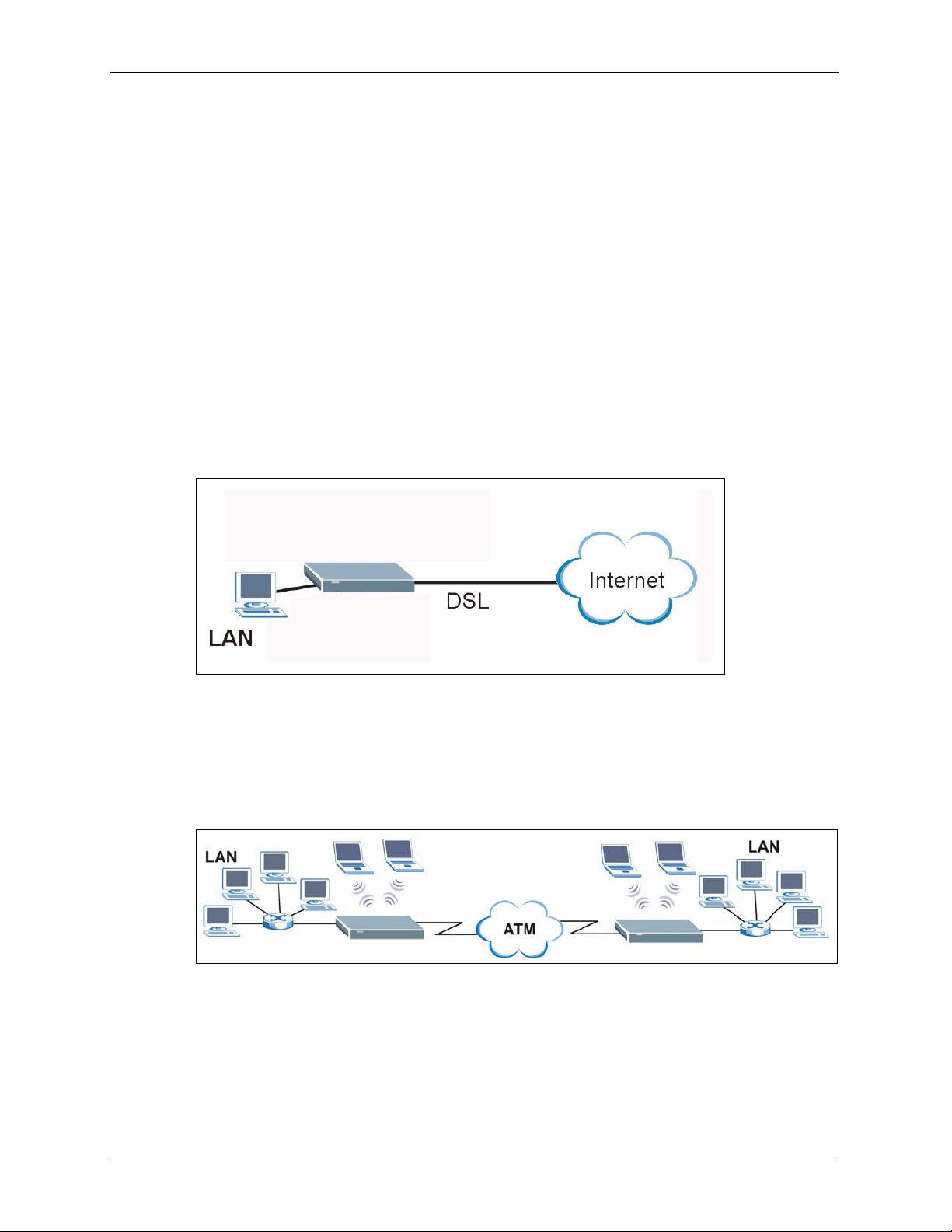
1.3.1 Internet Access
The ZyXEL Device is the ideal high-speed Internet access solution. It is compatible with all
major ADSL DSLAM (Digital Subscriber Line Access Multiplexer) providers and supports
the ADSL standards as shown in Table 1 on page 25.
Figure 1 Internet Access Applications
1.3.2 LAN to LAN Application
You can use the ZyXEL Device to connect two geographically dispersed networks over the
ADSL line. A typical LAN-to-LAN application example is shown as follows.
Figure 2 LAN-to-LAN Application Example
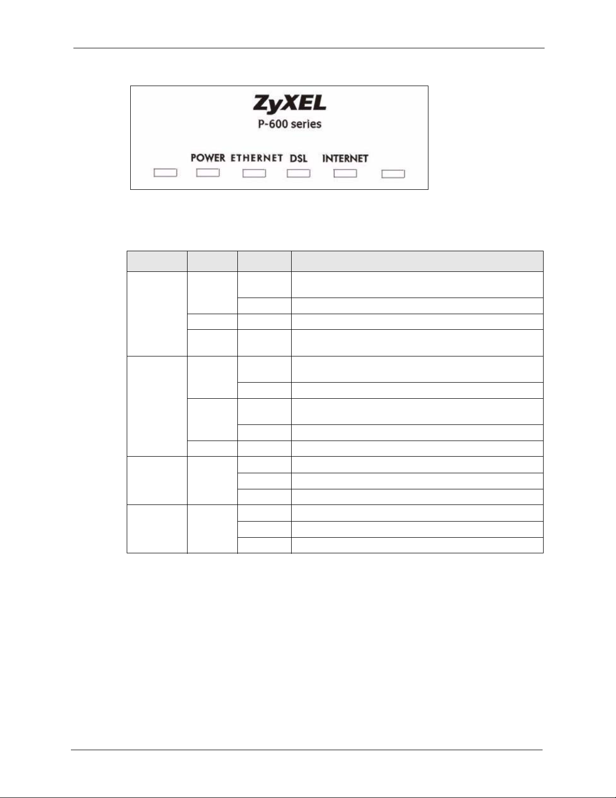
1.4 Front Panel Lights
The following figure shows the front panel lights.
27 Chapter 1 Getting To Know Your ZyXEL Device
Page 29
P-660R-D Series User’s Guide
Figure 3 Front Panel (P-660R-D1)
The following table describes the lights.
Table 2 Front Panel Lights
LIGHT COLOR STATUS DESCRIPTION
POWER Green On The ZyXEL Device is receiving power and functioning
properly.
Blinking The ZyXEL Device is rebooting or performing diagnostics.
Red On Power to the ZyXEL Device is too low.
Off The ZyXEL Device is turned off. The system is not receiving
ETHERNET Green On The ZyXEL Device has a successful 10Mbps Ethernet
Blinking The ZyXEL Device is receiving or sending data.
Amber On The ZyXEL Device has a successful 100Mbps Ethernet
Blinking The ZyXEL Device is receiving or sending data.
Off The ZyXEL Device is not connected to the LAN.
DSL Green On The DSL line is up.
Blinking The ZyXEL Device is initializing the DSL line.
Off The DSL line is down.
INTERNET Green On The Internet connection is up.
Blinking The ZyXEL Device is sending/receiving data.
Off The Internet connection is down.
power.
connection.
connection.
1.5 Hardware Connection
Refer to the Quick Start Guide for information on hardware connection.
Chapter 1 Getting To Know Your ZyXEL Device 28
Page 30

P-660R-D Series User’s Guide
29 Chapter 1 Getting To Know Your ZyXEL Device
Page 31

Introducing the Web
This chapter describes how to access and navigate the web configurator.
2.1 Web Configurator Overview
The web configurator is an HTML-based management interface that allows easy ZyXEL
Device setup and management via Internet browser. Use Internet Explorer 6.0 and later or
Netscape Navigator 7.0 and later versions. The recommended screen resolution is 1024 by 768
pixels.
P-660R-D Series User’s Guide
CHAPTER 2
Configurator
In order to use the web configurator you need to allow:
• Web browser pop-up windows from your device. Web pop-up blocking is enabled by
default in Windows XP SP (Service Pack) 2.
• JavaScripts (enabled by default).
• Java permissions (enabled by default).
See the chapter on troubleshooting if you need to make sure these functions are allowed in
Internet Explorer.
2.2 Accessing the Web Configurator
1 Make sure your ZyXEL Device hardware is properly connected (refer to the Quick Start
Guide).
2 Prepare your computer/computer network to connect to the ZyXEL Device (refer to the
Quick Start Guide).
3 Launch your web browser.
4 Type "192.168.1.1" as the URL.
5 A window displays as shown. Enter the default admin password 1234 to configure the
wizards and the advanced features or enter the default user password user to view the
status only. Click Login to proceed to a screen asking you to change your password or
click Cancel to revert to the default password.
Chapter 2 Introducing the Web Configurator 30
Page 32

P-660R-D Series User’s Guide
Figure 4 Password Screen
6 If you entered the user password, skip the next two steps and refer to Section 2.4.2 on
page 34 for more information about the Status screen.
If you entered the admin password, it is highly recommended you change the default
admin password! Enter a new password between 1 and 30 characters, retype it to confirm
and click Apply; alternatively click Ignore to proceed to the main menu if you do not
want to change the password now.
Note: If you do not change the password at least once, the following screen appears
every time you log in with the admin password.
Figure 5 Change Password at Login
7 Select Go to Wizard setup and click Apply to display the wizard main screen.
Otherwise, select Go to Advanced setup and click Apply to display the Status screen.
31 Chapter 2 Introducing the Web Configurator
Page 33

P-660R-D Series User’s Guide
Figure 6 Select a Mode
Note: The management session automatically times out when the time period set in
the Administrator Inactivity Timer field expires (default five minutes). Simply
log back into the ZyXEL Device if this happens to you.
2.3 Resetting the ZyXEL Device
If you forget your password or cannot access the web configurator, you will need to use the
RESET button at the back of the ZyXEL Device to reload the factory-default configuration
file. This means that you will lose all configurations that you had previously and the password
will be reset to “1234”.
2.3.1 Using the Reset Button
1 Make sure the POWER light is on (not blinking).
2 Press the RESET button for ten seconds or until the POWER light begins to blink and
then release it. When the POWER light begins to blink, the defaults have been restored
and the ZyXEL Device restarts.
2.4 Navigating the Web Configurator
We use the P-660R-D1 web screens in this guide as an example. Screens vary slightly for
different ZyXEL Device models.
2.4.1 Navigation Panel
After you enter the admin password, use the sub-menus on the navigation panel to configure
ZyXEL Device features. The following table describes the sub-menus.
Chapter 2 Introducing the Web Configurator 32
Page 34

P-660R-D Series User’s Guide
Figure 7 Web Configurator: Main Screen
Use
submenus
to configure
ZyXEL
Device
features.
Click the Logout icon at any time
to exit the web configurator.
Note: Click the icon (located in the top right corner of most screens) to view
embedded help.
Table 3 Web Configurator Screens Summary
LINK/ICON SUB-LINK FUNCTION
Wizard INTERNET
SETUP
Logout Click this icon to exit the web configurator.
Status This screen shows the ZyXEL Device’s general device, system
Network
WAN Internet
Connection
More Connections Use this screen to view and configure other connections for
WAN Backup
Setup
LAN IP Use this screen to configure LAN TCP/IP settings, enable Any
DHCP Setup Use this screen to configure LAN DHCP settings.
Client List
IP Alias Use this screen to partition your LAN interface into subnets.
Use these screens for initial configuration including general
setup, ISP parameters for Internet Access and WAN IP/DNS
Server/MAC address assignment.
and interface status information. Use this screen to access the
summary statistics tables.
This screen allows you to configure ISP parameters, WAN IP
address assignment, DNS servers and other advanced
properties.
placing calls to another remote gateway.
Use this screen to configure your traffic redirect properties and
WAN backup settings.
IP and other advanced properties.
Use this screen to view current DHCP client information and to
always assign an IP address to a MAC address (and host
name).
33 Chapter 2 Introducing the Web Configurator
Page 35

P-660R-D Series User’s Guide
Table 3 Web Configurator Screens Summary (continued)
LINK/ICON SUB-LINK FUNCTION
NAT General Use this screen to enable NAT.
Port Forwarding Use this screen to configure servers behind the ZyXEL Device.
Advanced
Static Route Use this screen to configure IP static routes.
Dynamic DNS Use this screen to set up dynamic DNS.
Remote MGMT
UPnP Use this screen to enable UPnP on the ZyXEL Device.
Maintenance
System General This screen contains administrative and system-related
Tools Firmware Use this screen to upload firmware to your ZyXEL Device.
Diagnostic General These screens display information to help you identify problems
WWW Use this screen to configure through which interface(s) and
from which IP address(es) users can use HTTPS or HTTP to
manage the ZyXEL Device.
Te ln e t Use this screen to configure through which interface(s) and
from which IP address(es) users can use Telnet to manage the
ZyXEL Device.
FTP Use this screen to configure through which interface(s) and
from which IP address(es) users can use FTP to access the
ZyXEL Device.
SNMP Use this screen to configure your ZyXEL Device’s settings for
Simple Network Management Protocol management.
DNS Use this screen to configure through which interface(s) and
from which IP address(es) users can send DNS queries to the
ZyXEL Device.
ICMP Use this screen to change your anti-probing settings.
information and also allows you to change your password.
Time Setting Use this screen to change your ZyXEL Device’s time and date.
Configuration Use this screen to backup and restore the configuration or reset
the factory defaults to your ZyXEL Device.
Restart This screen allows you to reboot the ZyXEL Device without
turning the power off.
with the ZyXEL Device general connection.
DSL Line These screens display information to help you identify problems
with the DSL line.
2.4.2 Status Screen
The following summarizes how to navigate the web configurator from the Status screen.
Some fields or links are not available if you entered the user password in the login password
screen (see Figure 4 on page 31). Not all fields are available on all models.
Chapter 2 Introducing the Web Configurator 34
Page 36

P-660R-D Series User’s Guide
Figure 8 Status Screen
The following table describes the labels shown in the Status screen.
Table 4 Status Screen
LABEL DESCRIPTION
Refresh Interval Select a number of seconds or None from the drop-down list box to refresh all
screen statistics automatically at the end of every time interval or to not refresh the
screen statistics.
Apply Click this button to refresh the status screen statistics.
Device Information
Host Name This is the System Name you enter in the Maintenance > System > General
Model Number This is your ZyXEL Device’s model name.
MAC Address This is the MAC (Media Access Control) or Ethernet address unique to your ZyXEL
ZyNOS Firmware
Version
WAN Information
DSL Mode This is the standard that your ZyXEL Device is using.
IP Address
IP Subnet Mask
Default Gateway
VPI/VCI This is the Virtual Path Identifier and Virtual Channel Identifier that you entered in
LAN Information
IP Address This is the ETHERNET port IP address.
IP Subnet Mask This is the ETHERNET port IP subnet mask.
screen. It is for identification purposes.
Device.
This is the ZyNOS Firmware version and the date created. ZyNOS is ZyXEL's
proprietary Network Operating System design.
This is the DSL port IP address.
This is the DSL port IP subnet mask.
This is the IP address of the default gateway, if applicable.
the wizard or WAN screen.
35 Chapter 2 Introducing the Web Configurator
Page 37

P-660R-D Series User’s Guide
Table 4 Status Screen
LABEL DESCRIPTION
DHCP This is the ETHERNET port DHCP role - Server, Relay or None.
System Status
System Uptime This is the total time the ZyXEL Device has been on.
Current Date/Time This field displays your ZyXEL Device’s present date and time.
System Mode This displays whether the ZyXEL Device is functioning as a router or a bridge.
CPU Usage This number shows how many kilobytes of the heap memory the ZyXEL Device is
Memory Usage This number shows the ZyXEL Device's total heap memory (in kilobytes).
Interface Status
Interface This displays the ZyXEL Device port types.
Status This field displays Down (line is down), Up (line is up or connected) if you're using
using. Heap memory refers to the memory that is not used by ZyNOS (ZyXEL
Network Operating System) and is thus available for running processes like NAT,
VPN and the firewall.
The bar displays what percent of the ZyXEL Device's heap memory is in use. The
bar turns from green to red when the maximum is being approached.
The bar displays what percent of the ZyXEL Device's heap memory is in use. The
bar turns from green to red when the maximum is being approached.
Ethernet encapsulation and Down (line is down), Up (line is up or connected), Idle
(line (ppp) idle), Dial (starting to trigger a call) and Drop (dropping a call) if you're
using PPPoE encapsulation.
Rate For the LAN ports, this displays the port speed and duplex setting.
For the DSL port, it displays the downstream and upstream transmission rate.
Summary
Any IP Table Use this screen to view a list of IP addresses and MAC addresses of computers,
which are not in the same subnet as the ZyXEL Device.
Packet Statistics Use this screen to view port status and packet specific statistics.
2.4.3 Status: Any IP Table
Click the Any IP Table hyperlink in the Status screen. The Any IP table shows current read-
only information (including the IP address and the MAC address) of all network devices that
use the Any IP feature to communicate with the ZyXEL Device.
Figure 9 Status: Any IP Table
Chapter 2 Introducing the Web Configurator 36
Page 38

P-660R-D Series User’s Guide
The following table describes the labels in this screen.
Table 5 Status: Any IP Table
LABEL DESCRIPTION
# This is the index number of the host computer.
IP Address This field displays the IP address of the network device.
MAC Address This field displays the MAC (Media Access Control) address of the computer with the
displayed IP address.
Every Ethernet device has a unique MAC address. The MAC address is assigned at
the factory and consists of six pairs of hexadecimal characters, for example,
00:A0:C5:00:00:02.
Refresh Click Refresh to update this screen.
2.4.4 Status: Packet Statistics
Click the Packet Statistics hyperlink in the Status screen. Read-only information here
includes port status and packet specific statistics. Also provided are "system up time" and "poll
interval(s)". The Poll Interval(s) field is configurable. Not all fields are available on all
models
Figure 10 Status: Packet Statistics
37 Chapter 2 Introducing the Web Configurator
Page 39

P-660R-D Series User’s Guide
The following table describes the fields in this screen.
Table 6 Status: Packet Statistics
LABEL DESCRIPTION
System Monitor
System up Time This is the elapsed time the system has been up.
Current Date/Time This field displays your ZyXEL Device’s present date and time.
CPU Usage This field specifies the percentage of CPU utilization.
Memory Usage This field specifies the percentage of memory utilization.
LAN or WAN Port
Stat istics
Link Status This is the status of your WAN link.
Upstream Speed This is the upstream speed of your ZyXEL Device.
Downstream Speed This is the downstream speed of your ZyXEL Device.
Node-Link This field displays the remote node index number and link type. Link types are
Interface This field displays the type of port.
Status This field displays Down (line is down), Up (line is up or connected) if you're
TxPkts This field displays the number of packets transmitted on this port.
RxPkts This field displays the number of packets received on this port.
Errors This field displays the number of error packets on this port.
Tx B/s This field displays the number of bytes transmitted in the last second.
Rx B/s This field displays the number of bytes received in the last second.
Up Time This field displays the elapsed time this port has been up.
Collisions This is the number of collisions on this port.
Help Click this button to bring the help screen.
Poll Interval(s) Type the time interval for the browser to refresh system statistics.
Set Interval Click this button to apply the new poll interval you entered in the Poll Interval
Stop Click this button to halt the refreshing of the system statistics.
This is the WAN or LAN port.
PPPoA, ENET, RFC 1483 and PPPoE.
using Ethernet encapsulation and Down (line is down), Up (line is up or
connected), Idle (line (ppp) idle), Dial (starting to trigger a call) and Drop
(dropping a call) if you're using PPPoE encapsulation.
For the WLAN port, it displays the transmission rate when WLAN is enabled or
N/A when WLAN is disabled.
field above.
2.4.5 Changing Login Password
It is highly recommended that you periodically change the password for accessing the ZyXEL
Device. If you didn’t change the default one after you logged in or you want to change to a
new password again, then click Maintenance > System to display the screen as shown next.
See Table 42 on page 123 for detailed field descriptions.
Chapter 2 Introducing the Web Configurator 38
Page 40

P-660R-D Series User’s Guide
Figure 11 System General
39 Chapter 2 Introducing the Web Configurator
Page 41

P-660R-D Series User’s Guide
CHAPTER 3
Wizard Setup for Internet Access
This chapter provides information on the Wizard Setup screens for Internet access in the web
configurator.
3.1 Introduction
Use the wizard setup screens to configure your system for Internet access with the information
given to you by your ISP.
Note: See the advanced menu chapters for background information on these fields.
3.2 Internet Access Wizard Setup
1 After you enter the admin password to access the web configurator, select Go to Wizard
setup and click Apply. Otherwise, click the wizard icon ( ) in the top right corner of
the web configurator to display the wizard main screen.
Figure 12 Select a Mode
2 Click INTERNET SETUP to configure the system for Internet access.
Chapter 3 Wizard Setup for Internet Access 40
Page 42

P-660R-D Series User’s Guide
Figure 13 Wizard: Welcome
3 The wizard attempts to detect which WAN connection type you are using.
If the wizard detects your connection type and your ISP uses PPPoE or PPPoA, go to
Section 3.2.1 on page 42. The screen varies depending on the connection type you use.
If the wizard does not detect a connection type and the following screen appears (see
Figure 14 on page 41), check your hardware connections and click Restart the Internet
Setup Wizard to have the ZyXEL Device detect your connection again.
Figure 14 Auto Detection: No DSL Connection
If the wizard still cannot detect a connection type and the following screen appears (see
Figure 15 on page 42), click Next and refer to Section 3.2.2 on page 42 on how to
configure the ZyXEL Device for Internet access manually.
41 Chapter 3 Wizard Setup for Internet Access
Page 43

Figure 15 Auto Detection: Failed
3.2.1 Automatic Detection
1 If you have a PPPoE or PPPoA connection, a screen displays prompting you to enter your
Internet account information. Enter the username, password and/or service name exactly
as provided.
P-660R-D Series User’s Guide
2 Click Next to confirm your settings and test your connection.
Figure 16 Auto-Detection: PPPoE
3.2.2 Manual Configuration
1 If the ZyXEL Device fails to detect your DSL connection type, enter the Internet access
information given to you by your ISP exactly in the wizard screen. If not given, leave the
fields set to the default.
Chapter 3 Wizard Setup for Internet Access 42
Page 44

P-660R-D Series User’s Guide
Figure 17 Internet Access Wizard Setup: ISP Parameters
The following table describes the fields in this screen.
Table 7 Internet Access Wizard Setup: ISP Parameters
LABEL DESCRIPTION
Mode From the Mode drop-down list box, select Routing (default) if your ISP allows
multiple computers to share an Internet account. Otherwise select Bridge.
Encapsulation Select the encapsulation type your ISP uses from the Encapsulation drop-down list
box. Choices vary depending on what you select in the Mode field.
If you select Bridge in the Mode field, select either PPPoA or RFC 1483.
If you select Routing in the Mode field, select PPPoA, RFC 1483, ENET ENCAP or
PPPoE.
Multiplexing Select the multiplexing method used by your ISP from the Multiplex drop-down list
box either VC-based or LLC-based.
Virtual Circuit IDVPI (Virtual Path Identifier) and VCI (Virtual Channel Identifier) define a virtual circuit.
Refer to the appendix for more information.
VPI Enter the VPI assigned to you. This field may already be configured.
VCI Enter the VCI assigned to you. This field may already be configured.
Back Click Back to go back to the previous screen.
Next Click Next to continue to the next wizard screen. The next wizard screen you see
Exit Click Exit to close the wizard screen without saving your changes.
depends on what protocol you chose above.
2 The next wizard screen varies depending on what mode and encapsulation type you use.
All screens shown are with routing mode. Configure the fields and click Next to continue.
43 Chapter 3 Wizard Setup for Internet Access
Page 45

Figure 18 Internet Connection with PPPoE
The following table describes the fields in this screen.
P-660R-D Series User’s Guide
Table 8 Internet Connection with PPPoE
LABEL DESCRIPTION
User Name Enter the user name exactly as your ISP assigned. If assigned a name in the form
user@domain where domain identifies a service name, then enter both components
exactly as given.
Password Enter the password associated with the user name above.
Service Name Type the name of your PPPoE service here.
Back Click Back to go back to the previous wizard screen.
Apply Click Apply to save your changes back to the ZyXEL Device.
Exit Click Exit to close the wizard screen without saving your changes.
Figure 19 Internet Connection with RFC 1483
Chapter 3 Wizard Setup for Internet Access 44
Page 46

P-660R-D Series User’s Guide
The following table describes the fields in this screen.
Table 9 Internet Connection with RFC 1483
LABEL DESCRIPTION
IP Address This field is available if you select Routing in the Mode field.
Back Click Back to go back to the previous wizard screen.
Next Click Next to continue to the next wizard screen.
Exit Click Exit to close the wizard screen without saving your changes.
Figure 20 Internet Connection with ENET ENCAP
Type your ISP assigned IP address in this field.
The following table describes the fields in this screen.
Table 10 Internet Connection with ENET ENCAP
LABEL DESCRIPTION
Obtain an IP
Address
Automatically
Stat ic IP
Address
IP Address Enter your ISP assigned IP address.
Subnet Mask Enter a subnet mask in dotted decimal notation.
Gateway IP
address
First DNS
Server
45 Chapter 3 Wizard Setup for Internet Access
A static IP address is a fixed IP that your ISP gives you. A dynamic IP address is not
fixed; the ISP assigns you a different one each time you connect to the Internet.
Select Obtain an IP Address Automatically if you have a dynamic IP address.
Select Static IP Address if your ISP gives you a fixed IP address.
Refer to the appendices to calculate a subnet mask If you are implementing subnetting.
You must specify a gateway IP address (supplied by your ISP) when you use ENET
ENCAP in the Encapsulation field in the previous screen.
Enter the IP addresses of the DNS servers. The DNS servers are passed to the DHCP
clients along with the IP address and the subnet mask.
Page 47

Table 10 Internet Connection with ENET ENCAP (continued)
LABEL DESCRIPTION
P-660R-D Series User’s Guide
Second DNS
Server
Back Click Back to go back to the previous wizard screen.
Apply Click Apply to save your changes back to the ZyXEL Device.
Exit Click Exit to close the wizard screen without saving your changes.
As above.
Figure 21 Internet Connection with PPPoA
The following table describes the fields in this screen.
Table 11 Internet Connection with PPPoA
LABEL DESCRIPTION
User Name Enter the login name that your ISP gives you.
Password Enter the password associated with the user name above.
Back Click Back to go back to the previous wizard screen.
Apply Click Apply to save your changes back to the ZyXEL Device.
Exit Click Exit to close the wizard screen without saving your changes.
• If the user name and/or password you entered for PPPoE or PPPoA connection are not
correct, the screen displays as shown next. Click Back to Username and Password
setup to go back to the screen where you can modify them.
Chapter 3 Wizard Setup for Internet Access 46
Page 48

P-660R-D Series User’s Guide
Figure 22 Connection Test Failed-1
• If the following screen displays, check if your account is activated or click Restart the
Internet Setup Wizard to verify your Internet access settings.
Figure 23 Connection Test Failed-2.
When you are finished with the Internet Setup Wizard the following screen displays your
configuration details. Click Finish to exit the wizard.
Figure 24 Internet Setup Wizard Finished
47 Chapter 3 Wizard Setup for Internet Access
Page 49

This chapter describes how to configure WAN settings.
4.1 WAN Overview
A WAN (Wide Area Network) is an outside connection to another network or the Internet.
4.1.1 Encapsulation
Be sure to use the encapsulation method required by your ISP. The ZyXEL Device supports
the following methods.
P-660R-D Series User’s Guide
CHAPTER 4
WAN Setup
4.1.1.1 ENET ENCAP
The MAC Encapsulated Routing Link Protocol (ENET ENCAP) is only implemented with the
IP network protocol. IP packets are routed between the Ethernet interface and the WAN
interface and then formatted so that they can be understood in a bridged environment. For
instance, it encapsulates routed Ethernet frames into bridged ATM cells. ENET ENCAP
requires that you specify a gateway IP address in the ENET ENCAP Gateway field in the
second wizard screen. You can get this information from your ISP.
4.1.1.2 PPP over Ethernet
PPPoE (Point-to-Point Protocol over Ethernet) provides access control and billing
functionality in a manner similar to dial-up services using PPP. PPPoE is an IETF standard
(RFC 2516) specifying how a personal computer (PC) interacts with a broadband modem
(DSL, cable, wireless, etc.) connection.
For the service provider, PPPoE offers an access and authentication method that works with
existing access control systems (for example RADIUS).
One of the benefits of PPPoE is the ability to let you access one of multiple network services,
a function known as dynamic service selection. This enables the service provider to easily
create and offer new IP services for individuals.
Operationally, PPPoE saves significant effort for both you and the ISP or carrier, as it requires
no specific configuration of the broadband modem at the customer site.
Chapter 4 WAN Setup 48
Page 50

P-660R-D Series User’s Guide
By implementing PPPoE directly on the ZyXEL Device (rather than individual computers),
the computers on the LAN do not need PPPoE software installed, since the ZyXEL Device
does that part of the task. Furthermore, with NAT, all of the LANs’ computers will have
access.
4.1.1.3 PPPoA
PPPoA stands for Point to Point Protocol over ATM Adaptation Layer 5 (AAL5). A PPPoA
connection functions like a dial-up Internet connection. The ZyXEL Device encapsulates the
PPP session based on RFC1483 and sends it through an ATM PVC (Permanent Virtual
Circuit) to the Internet Service Provider’s (ISP) DSLAM (digital access multiplexer). Please
refer to RFC 2364 for more information on PPPoA. Refer to RFC 1661 for more information
on PPP.
4.1.1.4 RFC 1483
RFC 1483 describes two methods for Multiprotocol Encapsulation over ATM Adaptation
Layer 5 (AAL5). The first method allows multiplexing of multiple protocols over a single
ATM virtual circuit (LLC-based multiplexing) and the second method assumes that each
protocol is carried over a separate ATM virtual circuit (VC-based multiplexing). Please refer
to the RFC for more detailed information.
4.1.2 Multiplexing
There are two conventions to identify what protocols the virtual circuit (VC) is carrying. Be
sure to use the multiplexing method required by your ISP.
4.1.2.1 VC-based Multiplexing
In this case, by prior mutual agreement, each protocol is assigned to a specific virtual circuit;
for example, VC1 carries IP, etc. VC-based multiplexing may be dominant in environments
where dynamic creation of large numbers of ATM VCs is fast and economical.
4.1.2.2 LLC-based Multiplexing
In this case one VC carries multiple protocols with protocol identifying information being
contained in each packet header. Despite the extra bandwidth and processing overhead, this
method may be advantageous if it is not practical to have a separate VC for each carried
protocol, for example, if charging heavily depends on the number of simultaneous VCs.
4.1.3 Encapsulation and Multiplexing Scenarios
For Internet access you should use the encapsulation and multiplexing methods used by your
ISP. Consult your telephone company for information on encapsulation and multiplexing
methods for LAN-to-LAN applications, for example between a branch office and corporate
headquarters. There must be prior agreement on encapsulation and multiplexing methods
49 Chapter 4 WAN Setup
Page 51

because they cannot be automatically determined. What method(s) you use also depends on
how many VCs you have and how many different network protocols you need. The extra
overhead that ENET ENCAP encapsulation entails makes it a poor choice in a LAN-to-LAN
application. Here are some examples of more suitable combinations in such an application.
4.1.3.1 Scenario 1: One VC, Multiple Protocols
PPPoA (RFC-2364) encapsulation with VC-based multiplexing is the best combination
because no extra protocol identifying headers are needed. The PPP protocol already contains
this information.
4.1.3.2 Scenario 2: One VC, One Protocol (IP)
Selecting RFC-1483 encapsulation with VC-based multiplexing requires the least amount of
overhead (0 octets). However, if there is a potential need for multiple protocol support in the
future, it may be safer to select PPPoA encapsulation instead of RFC-1483, so you do not
need to reconfigure either computer later.
4.1.3.3 Scenario 3: Multiple VCs
P-660R-D Series User’s Guide
If you have an equal number (or more) of VCs than the number of protocols, then select RFC1483 encapsulation and VC-based multiplexing.
4.1.4 VPI and VCI
Be sure to use the correct Virtual Path Identifier (VPI) and Virtual Channel Identifier (VCI)
numbers assigned to you. The valid range for the VPI is 0 to 255 and for the VCI is 32 to
65535 (0 to 31 is reserved for local management of ATM traffic). Please see the appendix for
more information.
4.1.5 IP Address Assignment
A static IP is a fixed IP that your ISP gives you. A dynamic IP is not fixed; the ISP assigns you
a different one each time. The Single User Account feature can be enabled or disabled if you
have either a dynamic or static IP. However the encapsulation method assigned influences
your choices for IP address and ENET ENCAP gateway.
4.1.5.1 IP Assignment with PPPoA or PPPoE Encapsulation
If you have a dynamic IP, then the IP Address and ENET ENCAP Gateway fields are not
applicable (N/A). If you have a static IP, then you only need to fill in the IP Address field and
not the ENET ENCAP Gateway field.
4.1.5.2 IP Assignment with RFC 1483 Encapsulation
In this case the IP Address Assignment must be static with the same requirements for the IP
Address and ENET ENCAP Gateway fields as stated above.
Chapter 4 WAN Setup 50
Page 52

P-660R-D Series User’s Guide
4.1.5.3 IP Assignment with ENET ENCAP Encapsulation
In this case you can have either a static or dynamic IP. For a static IP you must fill in all the IP
Address and ENET ENCAP Gateway fields as supplied by your ISP. However for a
dynamic IP, the ZyXEL Device acts as a DHCP client on the WAN port and so the IP
Address and ENET ENCAP Gateway fields are not applicable (N/A) as the DHCP server
assigns them to the ZyXEL Device.
4.1.6 Nailed-Up Connection (PPP)
A nailed-up connection is a dial-up line where the connection is always up regardless of traffic
demand. The ZyXEL Device does two things when you specify a nailed-up connection. The
first is that idle timeout is disabled. The second is that the ZyXEL Device will try to bring up
the connection when turned on and whenever the connection is down. A nailed-up connection
can be very expensive for obvious reasons.
Do not specify a nailed-up connection unless your telephone company offers flat-rate service
or you need a constant connection and the cost is of no concern
4.1.7 NAT
NAT (Network Address Translation - NAT, RFC 1631) is the translation of the IP address of a
host in a packet, for example, the source address of an outgoing packet, used within one
network to a different IP address known within another network.
4.2 Metric
The metric represents the "cost of transmission". A router determines the best route for
transmission by choosing a path with the lowest "cost". RIP routing uses hop count as the
measurement of cost, with a minimum of "1" for directly connected networks. The number
must be between "1" and "15"; a number greater than "15" means the link is down. The
smaller the number, the lower the "cost".
The metric sets the priority for the ZyXEL Device’s routes to the Internet. If any two of the
default routes have the same metric, the ZyXEL Device uses the following pre-defined
priorities:
• Normal route: designated by the ISP (see Section 4.5 on page 54)
• Traffic-redirect route (see Section 4.7 on page 62)
• WAN-backup route, also called dial-backup (see Section 4.8 on page 63)
For example, if the normal route has a metric of "1" and the traffic-redirect route has a metric
of "2" and dial-backup route has a metric of "3", then the normal route acts as the primary
default route. If the normal route fails to connect to the Internet, the ZyXEL Device tries the
traffic-redirect route next. In the same manner, the ZyXEL Device uses the dial-backup route
if the traffic-redirect route also fails.
51 Chapter 4 WAN Setup
Page 53

If you want the dial-backup route to take first priority over the traffic-redirect route or even the
normal route, all you need to do is set the dial-backup route’s metric to "1" and the others to
"2" (or greater).
IP Policy Routing overrides the default routing behavior and takes priority over all of the
routes mentioned above.
4.3 Traffic Shaping
Traffic Shaping is an agreement between the carrier and the subscriber to regulate the average
rate and fluctuations of data transmission over an ATM network. This agreement helps
eliminate congestion, which is important for transmission of real time data such as audio and
video connections.
Peak Cell Rate (PCR) is the maximum rate at which the sender can send cells. This parameter
may be lower (but not higher) than the maximum line speed. 1 ATM cell is 53 bytes (424 bits),
so a maximum speed of 832Kbps gives a maximum PCR of 1962 cells/sec. This rate is not
guaranteed because it is dependent on the line speed.
P-660R-D Series User’s Guide
Sustained Cell Rate (SCR) is the mean cell rate of each bursty traffic source. It specifies the
maximum average rate at which cells can be sent over the virtual connection. SCR may not be
greater than the PCR.
Maximum Burst Size (MBS) is the maximum number of cells that can be sent at the PCR.
After MBS is reached, cell rates fall below SCR until cell rate averages to the SCR again. At
this time, more cells (up to the MBS) can be sent at the PCR again.
If the PCR, SCR or MBS is set to the default of "0", the system will assign a maximum value
that correlates to your upstream line rate.
The following figure illustrates the relationship between PCR, SCR and MBS.
Figure 25 Example of Traffic Shaping
Chapter 4 WAN Setup 52
Page 54

P-660R-D Series User’s Guide
4.3.1 ATM Traffic Classes
These are the basic ATM traffic classes defined by the ATM Forum Traffic Management 4.0
Specification.
4.3.1.1 Constant Bit Rate (CBR)
Constant Bit Rate (CBR) provides fixed bandwidth that is always available even if no data is
being sent. CBR traffic is generally time-sensitive (doesn't tolerate delay). CBR is used for
connections that continuously require a specific amount of bandwidth. A PCR is specified and
if traffic exceeds this rate, cells may be dropped. Examples of connections that need CBR
would be high-resolution video and voice.
4.3.1.2 Variable Bit Rate (VBR)
The Variable Bit Rate (VBR) ATM traffic class is used with bursty connections. Connections
that use the Variable Bit Rate (VBR) traffic class can be grouped into real time (VBR-RT) or
non-real time (VBR-nRT) connections.
The VBR-RT (real-time Variable Bit Rate) type is used with bursty connections that require
closely controlled delay and delay variation. It also provides a fixed amount of bandwidth (a
PCR is specified) but is only available when data is being sent. An example of an VBR-RT
connection would be video conferencing. Video conferencing requires real-time data transfers
and the bandwidth requirement varies in proportion to the video image's changing dynamics.
The VBR-nRT (non real-time Variable Bit Rate) type is used with bursty connections that do
not require closely controlled delay and delay variation. It is commonly used for "bursty"
traffic typical on LANs. PCR and MBS define the burst levels, SCR defines the minimum
level. An example of an VBR-nRT connection would be non-time sensitive data file transfers.
4.3.1.3 Unspecified Bit Rate (UBR)
The Unspecified Bit Rate (UBR) ATM traffic class is for bursty data transfers. However, UBR
doesn't guarantee any bandwidth and only delivers traffic when the network has spare
bandwidth. An example application is background file transfer.
4.4 Zero Configuration Internet Access
Once you turn on and connect the ZyXEL Device to a telephone jack, it automatically detects
the Internet connection settings (such as the VCI/VPI numbers and the encapsulation method)
from the ISP and makes the necessary configuration changes. In cases where additional
account information (such as an Internet account user name and password) is required or the
ZyXEL Device cannot connect to the ISP, you will be redirected to web screen(s) for
information input or troubleshooting.
Zero configuration for Internet access is disable when
53 Chapter 4 WAN Setup
Page 55

• the ZyXEL Device is in bridge mode
• you set the ZyXEL Device to use a static (fixed) WAN IP address.
4.5 Internet Connection
To change your ZyXEL Device’s WAN Internet access settings, click Network > WAN. The
screen differs by the encapsulation.
See Section 4.1 on page 48 for more information.
Figure 26 Internet Connection (PPPoE)
P-660R-D Series User’s Guide
The following table describes the labels in this screen.
Table 12 Internet Connection
LABEL DESCRIPTION
General
Name Enter the name of your Internet Service Provider, e.g., MyISP. This information is
Mode Select Routing (default) from the drop-down list box if your ISP allows multiple
Chapter 4 WAN Setup 54
for identification purposes only.
computers to share an Internet account. Otherwise select Bridge.
Page 56

P-660R-D Series User’s Guide
Table 12 Internet Connection (continued)
LABEL DESCRIPTION
Encapsulation Select the method of encapsulation used by your ISP from the drop-down list
User Name (PPPoA and PPPoE encapsulation only) Enter the user name exactly as your
Password (PPPoA and PPPoE encapsulation only) Enter the password associated with the
Service Name (PPPoE only) Type the name of your PPPoE service here.
Multiplexing Select the method of multiplexing used by your ISP from the drop-down list.
Virtual Circuit ID VPI (Virtual Path Identifier) and VCI (Virtual Channel Identifier) define a virtual
VPI The valid range for the VPI is 0 to 255. Enter the VPI assigned to you.
VCI The valid range for the VCI is 32 to 65535 (0 to 31 is reserved for local
IP Address This option is available if you select Routing in the Mode field.
Subnet Mask
(ENET ENCAP
encapsulation only)
Gateway IP address
(ENET ENCAP
encapsulation only)
Connection
(PPPoA and PPPoE
encapsulation only)
Nailed-Up
Connection
Connect on Demand Select Connect on Demand when you don't want the connection up all the time
Max Idle Timeout Specify an idle time-out in the Max Idle Timeout field when you select Connect
Apply Click Apply to save the changes.
box. Choices vary depending on the mode you select in the Mode field.
If you select Bridge in the Mode field, select either PPPoA or RFC 1483.
If you select Routing in the Mode field, select PPPoA, RFC 1483, ENET
ENCAP or PPPoE.
ISP assigned. If assigned a name in the form user@domain where domain
identifies a service name, then enter both components exactly as given.
user name above.
Choices are VC or LLC.
circuit. Refer to the appendix for more information.
management of ATM traffic). Enter the VCI assigned to you.
A static IP address is a fixed IP that your ISP gives you. A dynamic IP address is
not fixed; the ISP assigns you a different one each time you connect to the
Internet.
If you use the encapsulation type except RFC 1483, select Obtain an IP
Address Automatically when you have a dynamic IP address; otherwise select
Static IP Address and type your ISP assigned IP address in the IP Address
field below.
If you use RFC 1483, enter the IP address given by your ISP in the IP Address
field.
Enter a subnet mask in dotted decimal notation.
Refer to the appendices to calculate a subnet mask If you are implementing
subnetting.
You must specify a gateway IP address (supplied by your ISP) when you select
ENET ENCAP in the Encapsulation field
Select Nailed-Up Connection when you want your connection up all the time.
The ZyXEL Device will try to bring up the connection automatically if it is
disconnected.
and specify an idle time-out in the Max Idle Timeout field.
on Demand. The default setting is 0, which means the Internet session will not
timeout.
55 Chapter 4 WAN Setup
Page 57

P-660R-D Series User’s Guide
Table 12 Internet Connection (continued)
LABEL DESCRIPTION
Cancel Click Cancel to begin configuring this screen afresh.
Advanced Setup Click this button to display the Advanced Internet Connection Setup screen
and edit more details of your WAN setup.
4.5.1 Configuring Advanced Internet Connection Setup
To edit your ZyXEL Device's advanced WAN settings, click the Advanced Setup button in
the Internet Connection screen. The screen appears as shown.
Figure 27 Advanced Internet Connection Setup
The following table describes the labels in this screen.
Table 13 Advanced Internet Connection Setup
LABEL DESCRIPTION
RIP & Multicast
Setup
RIP Direction Select the RIP direction from None, Both, In Only and Out Only.
RIP Version Select the RIP version from RIP-1, RIP-2B and RIP-2M.
Multicast IGMP (Internet Group Multicast Protocol) is a network-layer protocol used to
ATM QoS
Chapter 4 WAN Setup 56
establish membership in a multicast group. The ZyXEL Device supports both IGMP
version 1 (IGMP-v1) and IGMP-v2. Select None to disable it.
Page 58

P-660R-D Series User’s Guide
Table 13 Advanced Internet Connection Setup (continued)
LABEL DESCRIPTION
ATM QoS Type Select CBR (Continuous Bit Rate) to specify fixed (always-on) bandwidth for voice
Peak Cell Rate Divide the DSL line rate (bps) by 424 (the size of an ATM cell) to find the Peak Cell
Sustain Cell Rate The Sustain Cell Rate (SCR) sets the average cell rate (long-term) that can be
Maximum Burst
Size
Zero
Configuration
PPPoE
Passthrough
(PPPoE
encapsulation
only)
Back Click Back to return to the previous screen.
Apply Click Apply to save the changes.
Cancel Click Cancel to begin configuring this screen afresh.
or data traffic. Select UBR (Unspecified Bit Rate) for applications that are non-time
sensitive, such as e-mail. Select VBR-nRT (Variable Bit Rate-non Real Time) or
VBR-RT (Variable Bit Rate-Real Time) for bursty traffic and bandwidth sharing with
other applications.
Rate (PCR). This is the maximum rate at which the sender can send cells. Type the
PCR here.
transmitted. Type the SCR, which must be less than the PCR. Note that system
default is 0 cells/sec.
Maximum Burst Size (MBS) refers to the maximum number of cells that can be sent
at the peak rate. Type the MBS, which is less than 65535.
This feature is not applicable/available when you configure the ZyXEL Device to
use a static WAN IP address or in bridge mode.
Select Yes to set the ZyXEL Device to automatically detect the Internet connection
settings (such as the VCI/VPI numbers and the encapsulation method) from the ISP
and make the necessary configuration changes.
Select No to disable this feature. You must manually configure the ZyXEL Device
for Internet access.
This field is available when you select PPPoE encapsulation.
In addition to the ZyXEL Device's built-in PPPoE client, you can enable PPPoE
pass through to allow up to ten hosts on the LAN to use PPPoE client software on
their computers to connect to the ISP via the ZyXEL Device. Each host can have a
separate account and a public WAN IP address.
PPPoE pass through is an alternative to NAT for application where NAT is not
appropriate.
Disable PPPoE pass through if you do not need to allow hosts on the LAN to use
PPPoE client software on their computers to connect to the ISP.
4.6 Configuring More Connections
This section describes the protocol-independent parameters for a remote network. They are
required for placing calls to a remote gateway and the network behind it across a WAN
connection. When you use the WAN > Internet Connection screen to set up Internet access,
you are configuring the first WAN connection.
Click Network > WAN > More Connections to display the screen as shown next.
57 Chapter 4 WAN Setup
Page 59

Figure 28 More Connections
The following table describes the labels in this screen.
Table 14 More Connections
P-660R-D Series User’s Guide
LABEL DESCRIPTION
# This is the index number of a connection.
Active This display whether this connection is activated. Clear the check box to disable
the connection. Select the check box to enable it.
Name This is the descriptive name for this connection.
VPI/VCI This is the VPI and VCI values used for this connection.
Encapsulation This is the method of encapsulation used for this connection.
Modify The first (ISP) connection is read-only in this screen. Use the WAN > Internet
Connection screen to edit it.
Click the edit icon to go to the screen where you can edit the connection.
Click the delete icon to remove an existing connection. You cannot remove the
first connection.
Apply Click Apply to save the changes.
Cancel Click Cancel to begin configuring this screen afresh.
4.6.1 More Connections Edit
Click the edit icon in the More Connections screen to configure a connection.
Chapter 4 WAN Setup 58
Page 60

P-660R-D Series User’s Guide
Figure 29 More Connections Edit
The following table describes the labels in this screen.
Table 15 More Connections Edit
LABEL DESCRIPTION
Active Select the check box to activate or clear the check box to deactivate this
connection.
Name Enter a unique, descriptive name of up to 13 ASCII characters for this
connection.
Mode Select Routing from the drop-down list box if your ISP allows multiple computers
Encapsulation Select the method of encapsulation used by your ISP from the drop-down list
59 Chapter 4 WAN Setup
to share an Internet account.
If you select Bridge, the ZyXEL Device will forward any packet that it does not
route to this remote node; otherwise, the packets are discarded.
box. Choices are PPPoA, RFC 1483, ENET ENCAP or PPPoE.
Page 61

P-660R-D Series User’s Guide
Table 15 More Connections Edit (continued)
LABEL DESCRIPTION
User Name (PPPoA and PPPoE encapsulation only) Enter the user name exactly as your
ISP assigned. If assigned a name in the form user@domain where domain
identifies a service name, then enter both components exactly as given.
Password (PPPoA and PPPoE encapsulation only) Enter the password associated with the
user name above.
Service Name (PPPoE only) Type the name of your PPPoE service here.
Multiplexing Select the method of multiplexing used by your ISP from the drop-down list.
Choices are VC or LLC.
By prior agreement, a protocol is assigned a specific virtual circuit, for example,
VC1 will carry IP. If you select VC, specify separate VPI and VCI numbers for
each protocol.
For LLC-based multiplexing or PPP encapsulation, one VC carries multiple
protocols with protocol identifying information being contained in each packet
header. In this case, only one set of VPI and VCI numbers need be specified for
all protocols.
VPI The valid range for the VPI is 0 to 255. Enter the VPI assigned to you.
VCI The valid range for the VCI is 32 to 65535 (0 to 31 is reserved for local
management of ATM traffic). Enter the VCI assigned to you.
IP Address This option is available if you select Routing in the Mode field.
A static IP address is a fixed IP that your ISP gives you. A dynamic IP address is
not fixed; the ISP assigns you a different one each time you connect to the
Internet.
If you use the encapsulation type except RFC 1483, select Obtain an IP
Address Automatically when you have a dynamic IP address; otherwise select
Static IP Address and type your ISP assigned IP address in the IP Address
field below.
If you use RFC 1483, enter the IP address given by your ISP in the IP Address
field.
Subnet Mask Enter a subnet mask in dotted decimal notation.
Refer to the appendices to calculate a subnet mask If you are implementing
subnetting.
Gateway IP address Specify a gateway IP address (supplied by your ISP).
Connection
Nailed-Up
Connection
Connect on Demand Select Connect on Demand when you don't want the connection up all the time
Max Idle Timeout Specify an idle time-out in the Max Idle Timeout field when you select Connect
NAT SUA only is available only when you select Routing in the Mode field.
Back Click Back to return to the previous screen.
Apply Click Apply to save the changes.
Select Nailed-Up Connection when you want your connection up all the time.
The ZyXEL Device will try to bring up the connection automatically if it is
disconnected.
and specify an idle time-out in the Max Idle Timeout field.
on Demand. The default setting is 0, which means the Internet session will not
timeout.
Select SUA Only if you have one public IP address and want to use NAT. Click
Edit to go to the Port Forwarding screen to edit a server mapping set.
Otherwise, select None to disable NAT.
Chapter 4 WAN Setup 60
Page 62

P-660R-D Series User’s Guide
Table 15 More Connections Edit (continued)
LABEL DESCRIPTION
Cancel Click Cancel to begin configuring this screen afresh.
Advanced Setup Click this button to display the More Connections Advanced screen and edit
more details of your WAN setup.
4.6.2 Configuring More Connections Advanced Setup
To edit your ZyXEL Device's advanced WAN settings, click the Advanced Setup button in
the More Connections Edit screen. The screen appears as shown.
Figure 30 More Connections Advanced Setup
The following table describes the labels in this screen.
Table 16 More Connections Advanced Setup
LABEL DESCRIPTION
RIP & Multicast
Setup
RIP Direction Select the RIP direction from None, Both, In Only and Out Only.
RIP Version Select the RIP version from RIP-1, RIP-2B and RIP-2M.
Multicast IGMP (Internet Group Multicast Protocol) is a network-layer protocol used to
establish membership in a multicast group. The ZyXEL Device supports both IGMP
version 1 (IGMP-v1) and IGMP-v2. Select None to disable it.
ATM QoS
ATM QoS Type Select CBR (Continuous Bit Rate) to specify fixed (always-on) bandwidth for voice
or data traffic. Select UBR (Unspecified Bit Rate) for applications that are non-time
sensitive, such as e-mail. Select VBR-nRT (Variable Bit Rate-non Real Time) or
VBR-RT (Variable Bit Rate-Real Time) for bursty traffic and bandwidth sharing with
other applications.
61 Chapter 4 WAN Setup
Page 63

Table 16 More Connections Advanced Setup (continued)
LABEL DESCRIPTION
Peak Cell Rate Divide the DSL line rate (bps) by 424 (the size of an ATM cell) to find the Peak Cell
Rate (PCR). This is the maximum rate at which the sender can send cells. Type the
PCR here.
Sustain Cell Rate The Sustain Cell Rate (SCR) sets the average cell rate (long-term) that can be
transmitted. Type the SCR, which must be less than the PCR. Note that system
default is 0 cells/sec.
Maximum Burst
Size
Back Click Back to return to the previous screen.
Apply Click Apply to save the changes.
Cancel Click Cancel to begin configuring this screen afresh.
Maximum Burst Size (MBS) refers to the maximum number of cells that can be sent
at the peak rate. Type the MBS, which is less than 65535.
4.7 Traffic Redirect
Traffic redirect forwards traffic to a backup gateway when the ZyXEL Device cannot connect
to the Internet. An example is shown in the figure below.
P-660R-D Series User’s Guide
Figure 31 Traffic Redirect Example
The following network topology allows you to avoid triangle route security issues when the
backup gateway is connected to the LAN. Use IP alias to configure the LAN into two or three
logical networks with the ZyXEL Device itself as the gateway for each LAN network. Put the
protected LAN in one subnet (Subnet 1 in the following figure) and the backup gateway in
another subnet (Subnet 2). Configure filters that allow packets from the protected LAN
(Subnet 1) to the backup gateway (Subnet 2).
Chapter 4 WAN Setup 62
Page 64

P-660R-D Series User’s Guide
Figure 32 Traffic Redirect LAN Setup
4.8 Configuring WAN Backup
To change your ZyXEL Device’s WAN backup settings, click Network > WAN > WAN
Backup Setup. The screen appears as shown.
Figure 33 WAN Backup Setup
63 Chapter 4 WAN Setup
Page 65

P-660R-D Series User’s Guide
The following table describes the labels in this screen.
Table 17 WAN Backup Setup
LABEL DESCRIPTION
Backup Type Select the method that the ZyXEL Device uses to check the DSL connection.
Select DSL Link to have the ZyXEL Device check if the connection to the DSLAM is
up. Select ICMP to have the ZyXEL Device periodically ping the IP addresses
configured in the Check WAN IP Address fields.
Check WAN IP
Address1-3
Configure this field to test your ZyXEL Device's WAN accessibility. Type the IP
address of a reliable nearby computer (for example, your ISP's DNS server
address).
Note: If you activate either traffic redirect or dial backup, you must
configure at least one IP address here.
When using a WAN backup connection, the ZyXEL Device periodically pings the
addresses configured here and uses the other WAN backup connection (if
configured) if there is no response.
Fail Tolerance Type the number of times (2 recommended) that your ZyXEL Device may ping the
IP addresses configured in the Check WAN IP Address field without getting a
response before switching to a WAN backup connection (or a different WAN
backup connection).
Recovery Interval When the ZyXEL Device is using a lower priority connection (usually a WAN backup
Timeout Type the number of seconds (3 recommended) for your ZyXEL Device to wait for a
Traffic Redirect Traffic redirect forwards traffic to a backup gateway when the ZyXEL Device cannot
Active Traffic
Redirect
connection), it periodically checks to whether or not it can use a higher priority
connection.
Type the number of seconds (30 recommended) for the ZyXEL Device to wait
between checks. Allow more time if your destination IP address handles lots of
traffic.
ping response from one of the IP addresses in the Check WAN IP Address field
before timing out the request. The WAN connection is considered "down" after the
ZyXEL Device times out the number of times specified in the Fail Tolerance field.
Use a higher value in this field if your network is busy or congested.
connect to the Internet.
Select this check box to have the ZyXEL Device use traffic redirect if the normal
WAN connection goes down.
Note: If you activate traffic redirect, you must configure at least one
Check WAN IP Address.
Metric This field sets this route's priority among the routes the ZyXEL Device uses.
The metric represents the "cost of transmission". A router determines the best route
for transmission by choosing a path with the lowest "cost". RIP routing uses hop
count as the measurement of cost, with a minimum of "1" for directly connected
networks. The number must be between "1" and "15"; a number greater than "15"
means the link is down. The smaller the number, the lower the "cost".
Backup Gateway Type the IP address of your backup gateway in dotted decimal notation. The ZyXEL
Device automatically forwards traffic to this IP address if the ZyXEL Device's
Internet connection terminates.
Apply Click Apply to save the changes.
Cancel Click Cancel to begin configuring this screen afresh.
Chapter 4 WAN Setup 64
Page 66

P-660R-D Series User’s Guide
65 Chapter 4 WAN Setup
Page 67

This chapter describes how to configure LAN settings.
5.1 LAN Overview
A Local Area Network (LAN) is a shared communication system to which many computers
are attached. A LAN is a computer network limited to the immediate area, usually the same
building or floor of a building. The LAN screens can help you configure a LAN DHCP server
and manage IP addresses.
See Section 5.3 on page 72 to configure the LAN screens.
P-660R-D Series User’s Guide
CHAPTER 5
LAN Setup
5.1.1 LANs, WANs and the ZyXEL Device
The actual physical connection determines whether the ZyXEL Device ports are LAN or
WAN ports. There are two separate IP networks, one inside the LAN network and the other
outside the WAN network as shown next.
Figure 34 LAN and WAN IP Addresses
Chapter 5 LAN Setup 66
Page 68

P-660R-D Series User’s Guide
5.1.2 DHCP Setup
DHCP (Dynamic Host Configuration Protocol, RFC 2131 and RFC 2132) allows individual
clients to obtain TCP/IP configuration at start-up from a server. You can configure the ZyXEL
Device as a DHCP server or disable it. When configured as a server, the ZyXEL Device
provides the TCP/IP configuration for the clients. If you turn DHCP service off, you must
have another DHCP server on your LAN, or else the computer must be manually configured.
5.1.2.1 IP Pool Setup
The ZyXEL Device is pre-configured with a pool of IP addresses for the DHCP clients (DHCP
Pool). See the product specifications in the appendices. Do not assign static IP addresses from
the DHCP pool to your LAN computers.
5.1.3 DNS Server Address
DNS (Domain Name System) is for mapping a domain name to its corresponding IP address
and vice versa. The DNS server is extremely important because without it, you must know the
IP address of a machine before you can access it. The DNS server addresses that you enter in
the DHCP setup are passed to the client machines along with the assigned IP address and
subnet mask.
There are two ways that an ISP disseminates the DNS server addresses. The first is for an ISP
to tell a customer the DNS server addresses, usually in the form of an information sheet, when
s/he signs up. If your ISP gives you the DNS server addresses, enter them in the DNS Server
fields in DHCP Setup, otherwise, leave them blank.
Some ISP’s choose to pass the DNS servers using the DNS server extensions of PPP IPCP (IP
Control Protocol) after the connection is up. If your ISP did not give you explicit DNS servers,
chances are the DNS servers are conveyed through IPCP negotiation. The ZyXEL Device
supports the IPCP DNS server extensions through the DNS proxy feature.
If the Primary and Secondary DNS Server fields in the DHCP Setup screen are not
specified, for instance, left as 0.0.0.0, the ZyXEL Device tells the DHCP clients that it itself is
the DNS server. When a computer sends a DNS query to the ZyXEL Device, the ZyXEL
Device forwards the query to the real DNS server learned through IPCP and relays the
response back to the computer.
Please note that DNS proxy works only when the ISP uses the IPCP DNS server extensions. It
does not mean you can leave the DNS servers out of the DHCP setup under all circumstances.
If your ISP gives you explicit DNS servers, make sure that you enter their IP addresses in the
DHCP Setup screen. This way, the ZyXEL Device can pass the DNS servers to the computers
and the computers can query the DNS server directly without the ZyXEL Device’s
intervention.
67 Chapter 5 LAN Setup
Page 69

5.1.4 DNS Server Address Assignment
Use DNS (Domain Name System) to map a domain name to its corresponding IP address and
vice versa. The DNS server is extremely important because without it, you must know the IP
address of a computer before you can access it.
There are two ways that an ISP disseminates the DNS server addresses.
• The ISP tells you the DNS server addresses, usually in the form of an information sheet,
when you sign up. If your ISP gives you DNS server addresses, enter them in the DNS
Server fields in the DHCP Setup screen.
• The ZyXEL Device acts as a DNS proxy when the Primary and Secondary DNS Server
fields are left as 0.0.0.0 in the DHCP Setup screen.
5.2 LAN TCP/IP
The ZyXEL Device has built-in DHCP server capability that assigns IP addresses and DNS
servers to systems that support DHCP client capability.
P-660R-D Series User’s Guide
5.2.1 IP Address and Subnet Mask
Similar to the way houses on a street share a common street name, so too do computers on a
LAN share one common network number.
Where you obtain your network number depends on your particular situation. If the ISP or
your network administrator assigns you a block of registered IP addresses, follow their
instructions in selecting the IP addresses and the subnet mask.
If the ISP did not explicitly give you an IP network number, then most likely you have a single
user account and the ISP will assign you a dynamic IP address when the connection is
established. If this is the case, it is recommended that you select a network number from
192.168.0.0 to 192.168.255.0 and you must enable the Network Address Translation (NAT)
feature of the ZyXEL Device. The Internet Assigned Number Authority (IANA) reserved this
block of addresses specifically for private use; please do not use any other number unless you
are told otherwise. Let's say you select 192.168.1.0 as the network number; which covers 254
individual addresses, from 192.168.1.1 to 192.168.1.254 (zero and 255 are reserved). In other
words, the first three numbers specify the network number while the last number identifies an
individual computer on that network.
Once you have decided on the network number, pick an IP address that is easy to remember,
for instance, 192.168.1.1, for your ZyXEL Device, but make sure that no other device on your
network is using that IP address.
The subnet mask specifies the network number portion of an IP address. Your ZyXEL Device
will compute the subnet mask automatically based on the IP address that you entered. You
don't need to change the subnet mask computed by the ZyXEL Device unless you are
instructed to do otherwise.
Chapter 5 LAN Setup 68
Page 70

P-660R-D Series User’s Guide
5.2.1.1 Private IP Addresses
Every machine on the Internet must have a unique address. If your networks are isolated from
the Internet, for example, only between your two branch offices, you can assign any IP
addresses to the hosts without problems. However, the Internet Assigned Numbers Authority
(IANA) has reserved the following three blocks of IP addresses specifically for private
networks:
• 10.0.0.0 — 10.255.255.255
• 172.16.0.0 — 172.31.255.255
• 192.168.0.0 — 192.168.255.255
You can obtain your IP address from the IANA, from an ISP or it can be assigned from a
private network. If you belong to a small organization and your Internet access is through an
ISP, the ISP can provide you with the Internet addresses for your local networks. On the other
hand, if you are part of a much larger organization, you should consult your network
administrator for the appropriate IP addresses.
Note: Regardless of your particular situation, do not create an arbitrary IP address;
always follow the guidelines above. For more information on address
assignment, please refer to RFC 1597, Address Allocation for Private Internets
and RFC 1466, Guidelines for Management of IP Address Space.
5.2.2 RIP Setup
RIP (Routing Information Protocol) allows a router to exchange routing information with
other routers. The RIP Direction field controls the sending and receiving of RIP packets.
When set to:
• Both - the ZyXEL Device will broadcast its routing table periodically and incorporate
the RIP information that it receives.
• In Only - the ZyXEL Device will not send any RIP packets but will accept all RIP
packets received.
• Out Only - the ZyXEL Device will send out RIP packets but will not accept any RIP
packets received.
• None - the ZyXEL Device will not send any RIP packets and will ignore any RIP
packets received.
The Version field controls the format and the broadcasting method of the RIP packets that the
ZyXEL Device sends (it recognizes both formats when receiving). RIP-1 is universally
supported; but RIP-2 carries more information. RIP-1 is probably adequate for most networks,
unless you have an unusual network topology.
Both RIP-2B and RIP-2M sends the routing data in RIP-2 format; the difference being that
RIP-2B uses subnet broadcasting while RIP-2M uses multicasting.
69 Chapter 5 LAN Setup
Page 71

5.2.3 Multicast
Traditionally, IP packets are transmitted in one of either two ways - Unicast (1 sender - 1
recipient) or Broadcast (1 sender - everybody on the network). Multicast delivers IP packets to
a group of hosts on the network - not everybody and not just 1.
IGMP (Internet Group Multicast Protocol) is a network-layer protocol used to establish
membership in a Multicast group - it is not used to carry user data. IGMP version 2 (RFC
2236) is an improvement over version 1 (RFC 1112) but IGMP version 1 is still in wide use. If
you would like to read more detailed information about interoperability between IGMP
version 2 and version 1, please see sections 4 and 5 of RFC 2236. The class D IP address is
used to identify host groups and can be in the range 224.0.0.0 to 239.255.255.255. The address
224.0.0.0 is not assigned to any group and is used by IP multicast computers. The address
224.0.0.1 is used for query messages and is assigned to the permanent group of all IP hosts
(including gateways). All hosts must join the 224.0.0.1 group in order to participate in IGMP.
The address 224.0.0.2 is assigned to the multicast routers group.
The ZyXEL Device supports both IGMP version 1 (IGMP-v1) and IGMP version 2 (IGMP-
v2). At start up, the ZyXEL Device queries all directly connected networks to gather group
membership. After that, the ZyXEL Device periodically updates this information. IP
multicasting can be enabled/disabled on the ZyXEL Device LAN and/or WAN interfaces in
the web configurator (LAN; WAN). Select None to disable IP multicasting on these
interfaces.
P-660R-D Series User’s Guide
5.2.4 Any IP
Traditionally, you must set the IP addresses and the subnet masks of a computer and the
ZyXEL Device to be in the same subnet to allow the computer to access the Internet (through
the ZyXEL Device). In cases where your computer is required to use a static IP address in
another network, you may need to manually configure the network settings of the computer
every time you want to access the Internet via the ZyXEL Device.
With the Any IP feature and NAT enabled, the ZyXEL Device allows a computer to access the
Internet without changing the network settings (such as IP address and subnet mask) of the
computer, when the IP addresses of the computer and the ZyXEL Device are not in the same
subnet. Whether a computer is set to use a dynamic or static (fixed) IP address, you can simply
connect the computer to the ZyXEL Device and access the Internet.
The following figure depicts a scenario where a computer is set to use a static private IP
address in the corporate environment. In a residential house where a ZyXEL Device is
installed, you can still use the computer to access the Internet without changing the network
settings, even when the IP addresses of the computer and the ZyXEL Device are not in the
same subnet.
Chapter 5 LAN Setup 70
Page 72

P-660R-D Series User’s Guide
Figure 35 Any IP Example
The Any IP feature does not apply to a computer using either a dynamic IP address or a static
IP address that is in the same subnet as the ZyXEL Device’s IP address.
Note: You must enable NAT/SUA to use the Any IP feature on the ZyXEL Device.
5.2.4.1 How Any IP Works
Address Resolution Protocol (ARP) is a protocol for mapping an Internet Protocol address (IP
address) to a physical machine address, also known as a Media Access Control or MAC
address, on the local area network. IP routing table is defined on IP Ethernet devices (the
ZyXEL Device) to decide which hop to use,
destination.
The following lists out the steps taken, when a computer tries to access the Internet for the first
time through the ZyXEL Device.
1 When a computer (which is in a different subnet) first attempts to access the Internet, it
sends packets to its default gateway (which is not the ZyXEL Device) by looking at the
MAC address in its ARP table.
2 When the computer cannot locate the default gateway, an ARP request is broadcast on the
LAN.
3 The ZyXEL Device receives the ARP request and replies to the computer with its own
MAC address.
4 The computer updates the MAC address for the default gateway to the ARP table. Once
the ARP table is updated, the computer is able to access the Internet through the ZyXEL
Device.
to help forward data along to its specified
5 When the ZyXEL Device receives packets from the computer, it creates an entry in the IP
routing table so it can properly forward packets intended for the computer.
After all the routing information is updated, the computer can access the ZyXEL Device and
the Internet as if it is in the same subnet as the ZyXEL Device.
71 Chapter 5 LAN Setup
Page 73

5.3 Configuring LAN IP
Click LAN to open the IP screen. See Section 5.1 on page 66 for background information.
Figure 36 LAN IP
The following table describes the fields in this screen.
Table 18 LAN IP
LABEL DESCRIPTION
P-660R-D Series User’s Guide
TCP/IP
IP Address Enter the IP address of your ZyXEL Device in dotted decimal notation, for
example, 192.168.1.1 (factory default).
IP Subnet Mask Type the subnet mask assigned to you by your ISP (if given).
Apply Click Apply to save your changes back to the ZyXEL Device.
Cancel Click Cancel to begin configuring this screen afresh.
Advanced Setup Click this button to display the Advanced LAN Setup screen and edit more
details of your LAN setup.
5.3.1 Configuring Advanced LAN Setup
To edit your ZyXEL Device's advanced LAN settings, click the Advanced Setup button in the
LAN IP screen. The screen appears as shown.
Chapter 5 LAN Setup 72
Page 74

P-660R-D Series User’s Guide
Figure 37 Advanced LAN Setup
The following table describes the labels in this screen.
Table 19 Advanced LAN Setup
LABEL DESCRIPTION
RIP & Multicast
Setup
RIP Direction Select the RIP direction from None, Both, In Only and Out Only.
RIP Version Select the RIP version from RIP-1, RIP-2B and RIP-2M.
Multicast IGMP (Internet Group Multicast Protocol) is a network-layer protocol used to
establish membership in a multicast group. The ZyXEL Device supports both IGMP
version 1 (IGMP-v1) and IGMP-v2. Select None to disable it.
Any IP Setup Select the Active check box to enable the Any IP feature. This allows a computer to
access the Internet without changing the network settings (such as IP address and
subnet mask) of the computer, even when the IP addresses of the computer and
the ZyXEL Device are not in the same subnet.
When you disable the Any IP feature, only computers with dynamic IP addresses or
static IP addresses in the same subnet as the ZyXEL Device’s LAN IP address can
connect to the ZyXEL Device or access the Internet through the ZyXEL Device.
Windows
Networking
(NetBIOS over
TCP/IP)
Allow between
LAN and WAN
Back Click Back to return to the previous screen.
Apply Click Apply to save the changes.
Cancel Click Cancel to begin configuring this screen afresh.
NetBIOS (Network Basic Input/Output System) are TCP or UDP packets that
enable a computer to connect to and communicate with a LAN. For some dial-up
services such as PPPoE or PPTP, NetBIOS packets cause unwanted calls.
However it may sometimes be necessary to allow NetBIOS packets to pass through
to the WAN in order to find a computer on the WAN.
Select this check box to forward NetBIOS packets from the LAN to the WAN and
from the WAN to the LAN. If your firewall is enabled with the default policy set to
block WAN to LAN traffic, you also need to enable the default WAN to LAN firewall
rule that forwards NetBIOS traffic.
Clear this check box to block all NetBIOS packets going from the LAN to the WAN
and from the WAN to the LAN.
73 Chapter 5 LAN Setup
Page 75

5.4 DHCP Setup
Use this screen to configure the DNS server information that the ZyXEL Device sends to the
DHCP client devices on the LAN.
Figure 38 DHCP Setup
P-660R-D Series User’s Guide
The following table describes the labels in this screen.
Table 20 DHCP Setup
LABEL DESCRIPTION
DHCP Setup
DHCP If set to Server, your ZyXEL Device can assign IP addresses, an IP default
IP Pool Starting
Address
Pool Size This field specifies the size, or count of the IP address pool.
Remote DHCP
Server
DNS Server
DNS Servers
Assigned by DHCP
Server
gateway and DNS servers to Windows 95, Windows NT and other systems that
support the DHCP client.
If set to None, the DHCP server will be disabled.
If set to Relay, the ZyXEL Device acts as a surrogate DHCP server and relays
DHCP requests and responses between the remote server and the clients.
Enter the IP address of the actual, remote DHCP server in the Remote DHCP
Server field in this case.
When DHCP is used, the following items need to be set:
This field specifies the first of the contiguous addresses in the IP address pool.
If Relay is selected in the DHCP field above then enter the IP address of the
actual remote DHCP server here.
The ZyXEL Device passes a DNS (Domain Name System) server IP address to
the DHCP clients.
Chapter 5 LAN Setup 74
Page 76

P-660R-D Series User’s Guide
Table 20 DHCP Setup
LABEL DESCRIPTION
Primary DNS Server
Secondary DNS
Server
Apply Click Apply to save your changes back to the ZyXEL Device.
Reset Click Reset to begin configuring this screen afresh.
5.5 LAN Client List
This table allows you to assign IP addresses on the LAN to specific individual computers
based on their MAC Addresses.
Every Ethernet device has a unique MAC (Media Access Control) address. The MAC address
is assigned at the factory and consists of six pairs of hexadecimal characters, for example,
00:A0:C5:00:00:02.
To change your ZyXEL Device’s static DHCP settings, click Network > LAN > Client List.
The screen appears as shown.
This field is not available when you set DHCP to Relay.
Enter the IP addresses of the DNS servers. The DNS servers are passed to the
DHCP clients along with the IP address and the subnet mask.
If the fields are left as 0.0.0.0, the ZyXEL Device acts as a DNS proxy and
forwards the DHCP client’s DNS query to the real DNS server learned through
IPCP and relays the response back to the computer.
Figure 39 LAN Client List
75 Chapter 5 LAN Setup
Page 77

P-660R-D Series User’s Guide
The following table describes the labels in this screen.
Table 21 LAN Client List
LABEL DESCRIPTION
IP Address Enter the IP address that you want to assign to the computer on your LAN with the
MAC address specified below.
The IP address should be within the range of IP addresses you specified in the
DHCP Setup for the DHCP client.
MAC Address Enter the MAC address of a computer on your LAN.
Add Click Add to add a static DHCP entry.
# This is the index number of the static IP table entry (row).
Status This field displays whether the client is connected to the ZyXEL Device.
Host Name This field displays the computer host name.
IP Address This field displays the IP address relative to the # field listed above.
MAC Address The MAC (Media Access Control) or Ethernet address on a LAN (Local Area
Network) is unique to your computer (six pairs of hexadecimal notation).
A network interface card such as an Ethernet adapter has a hardwired address
that is assigned at the factory. This address follows an industry standard that
ensures no other adapter has a similar address.
Reserve Select the check box(es) in each entry to have the ZyXEL Device always assign
Modify Click the modify icon to have the IP address field editable and change it.
Apply Click Apply to save your changes back to the ZyXEL Device.
Cancel Click Cancel to begin configuring this screen afresh.
Refresh Click Refresh to reload the DHCP table.
the selected entry(ies)’s IP address(es) to the corresponding MAC address(es)
(and host name(s)). You can select up to 32 entries in this table.
5.6 LAN IP Alias
IP alias allows you to partition a physical network into different logical networks over the
same Ethernet interface. The ZyXEL Device supports three logical LAN interfaces via its
single physical Ethernet interface with the ZyXEL Device itself as the gateway for each LAN
network.
Note: Make sure that the subnets of the logical networks do not overlap.
The following figure shows a LAN divided into subnets A, B, and C.
Chapter 5 LAN Setup 76
Page 78

P-660R-D Series User’s Guide
Figure 40 Physical Network & Partitioned Logical Networks
To change your ZyXEL Device’s IP alias settings, click Network > LAN > IP Alias. The
screen appears as shown.
Figure 41 LAN IP Alias
The following table describes the labels in this screen.
Table 22 LAN IP Alias
LABEL DESCRIPTION
IP Alias 1, 2 Select the check box to configure another LAN network for the ZyXEL Device.
IP Address Enter the IP address of your ZyXEL Device in dotted decimal notation.
Alternatively, click the right mouse button to copy and/or paste the IP address.
IP Subnet Mask Your ZyXEL Device will automatically calculate the subnet mask based on the IP
77 Chapter 5 LAN Setup
address that you assign. Unless you are implementing subnetting, use the subnet
mask computed by the ZyXEL Device.
Page 79

P-660R-D Series User’s Guide
Table 22 LAN IP Alias
LABEL DESCRIPTION
RIP Direction RIP (Routing Information Protocol, RFC 1058 and RFC 1389) allows a router to
exchange routing information with other routers. The RIP Direction field controls
the sending and receiving of RIP packets. Select the RIP direction from Both/In
Only/Out Only/None. When set to Both or Out Only, the ZyXEL Device will
broadcast its routing table periodically. When set to Both or In Only, it will
incorporate the RIP information that it receives; when set to None, it will not send
any RIP packets and will ignore any RIP packets received.
RIP Version The RIP Version field controls the format and the broadcasting method of the RIP
packets that the ZyXEL Device sends (it recognizes both formats when receiving).
RIP-1 is universally supported but RIP-2 carries more information. RIP-1 is
probably adequate for most networks, unless you have an unusual network
topology. Both RIP-2B and RIP-2M sends the routing data in RIP-2 format; the
difference being that RIP-2B uses subnet broadcasting while RIP-2M uses
multicasting. Multicasting can reduce the load on non-router machines since they
generally do not listen to the RIP multicast address and so will not receive the RIP
packets. However, if one router uses multicasting, then all routers on your network
must use multicasting, also. By default, RIP direction is set to Both and the
Version set to RIP-1.
Apply Click Apply to save your changes back to the ZyXEL Device.
Cancel Click Cancel to begin configuring this screen afresh.
Chapter 5 LAN Setup 78
Page 80

P-660R-D Series User’s Guide
79 Chapter 5 LAN Setup
Page 81

Network Address Translation
This chapter discusses how to configure NAT on the ZyXEL Device.
6.1 NAT Overview
NAT (Network Address Translation - NAT, RFC 1631) is the translation of the IP address of a
host in a packet, for example, the source address of an outgoing packet, used within one
network to a different IP address known within another network.
P-660R-D Series User’s Guide
CHAPTER 6
(NAT) Screens
6.1.1 NAT Definitions
Inside/outside denotes where a host is located relative to the ZyXEL Device, for example, the
computers of your subscribers are the inside hosts, while the web servers on the Internet are
the outside hosts.
Global/local denotes the IP address of a host in a packet as the packet traverses a router, for
example, the local address refers to the IP address of a host when the packet is in the local
network, while the global address refers to the IP address of the host when the same packet is
traveling in the WAN side.
Note that inside/outside refers to the location of a host, while global/local refers to the IP
address of a host used in a packet. Thus, an inside local address (ILA) is the IP address of an
inside host in a packet when the packet is still in the local network, while an inside global
address (IGA) is the IP address of the same inside host when the packet is on the WAN side.
The following table summarizes this information.
Table 23 NAT Definitions
ITEM DESCRIPTION
Inside This refers to the host on the LAN.
Outside This refers to the host on the WAN.
Local This refers to the packet address (source or destination) as the packet travels on the
LAN.
Global This refers to the packet address (source or destination) as the packet travels on the
WAN.
NAT never changes the IP address (either local or global) of an outside host.
Chapter 6 Network Address Translation (NAT) Screens 80
Page 82

P-660R-D Series User’s Guide
6.1.2 What NAT Does
In the simplest form, NAT changes the source IP address in a packet received from a
subscriber (the inside local address) to another (the inside global address) before forwarding
the packet to the WAN side. When the response comes back, NAT translates the destination
address (the inside global address) back to the inside local address before forwarding it to the
original inside host. Note that the IP address (either local or global) of an outside host is never
changed.
The global IP addresses for the inside hosts can be either static or dynamically assigned by the
ISP. In addition, you can designate servers, for example, a web server and a telnet server, on
your local network and make them accessible to the outside world. If you do not define any
servers (for Many-to-One and Many-to-Many Overload mapping – see Table 24 on page 83),
NAT offers the additional benefit of firewall protection. With no servers defined, your ZyXEL
Device filters out all incoming inquiries, thus preventing intruders from probing your network.
For more information on IP address translation, refer to RFC 1631, The IP Network Address
Translator (NAT).
6.1.3 How NAT Works
Each packet has two addresses – a source address and a destination address. For outgoing
packets, the ILA (Inside Local Address) is the source address on the LAN, and the IGA (Inside
Global Address) is the source address on the WAN. For incoming packets, the ILA is the
destination address on the LAN, and the IGA is the destination address on the WAN. NAT
maps private (local) IP addresses to globally unique ones required for communication with
hosts on other networks. It replaces the original IP source address (and TCP or UDP source
port numbers for Many-to-One and Many-to-Many Overload NAT mapping) in each packet
and then forwards it to the Internet. The ZyXEL Device keeps track of the original addresses
and port numbers so incoming reply packets can have their original values restored. The
following figure illustrates this.
Figure 42 How NAT Works
81 Chapter 6 Network Address Translation (NAT) Screens
Page 83

6.1.4 NAT Application
The following figure illustrates a possible NAT application, where three inside LANs (logical
LANs using IP Alias) behind the ZyXEL Device can communicate with three distinct WAN
networks. More examples follow at the end of this chapter.
Figure 43 NAT Application With IP Alias
P-660R-D Series User’s Guide
6.1.5 NAT Mapping Types
NAT supports five types of IP/port mapping. They are:
• One to One: In One-to-One mode, the ZyXEL Device maps one local IP address to one
global IP address.
• Many to One: In Many-to-One mode, the ZyXEL Device maps multiple local IP
addresses to one global IP address. This is equivalent to SUA (for instance, PAT, port
address translation), ZyXEL’s Single User Account feature that previous ZyXEL routers
supported (the SUA Only option in today’s routers).
• Many to Many Overload: In Many-to-Many Overload mode, the ZyXEL Device maps
the multiple local IP addresses to shared global IP addresses.
• Many-to-Many No Overload:
maps each local IP address to a unique global IP address.
• Server: This type allows you to specify inside servers of different services behind the
NAT to be accessible to the outside world.
Chapter 6 Network Address Translation (NAT) Screens 82
In Many-to-Many No Overload mode, the ZyXEL Device
Page 84

P-660R-D Series User’s Guide
Port numbers do NOT change for One-to-One and Many-to-Many No Overload NAT
mapping types.
The following table summarizes these types.
Table 24 NAT Mapping Types
TYPE IP MAPPING
One-to-One ILA1ÅÆ IGA1
Many-to-One (SUA/PAT) ILA1ÅÆ IGA1
Many-to-Many Overload ILA1ÅÆ IGA1
Many-to-Many No Overload ILA1ÅÆ IGA1
Server Server 1 IPÅÆ IGA1
ILA2ÅÆ IGA1
…
ILA2ÅÆ IGA2
ILA3ÅÆ IGA1
ILA4ÅÆ IGA2
…
ILA2ÅÆ IGA2
ILA3ÅÆ IGA3
…
Server 2 IPÅÆ IGA1
Server 3 IPÅÆ IGA1
6.2 SUA (Single User Account) Versus NAT
SUA (Single User Account) is a ZyNOS implementation of a subset of NAT that supports two
types of mapping, Many-to-One and Server. The ZyXEL Device also supports Full
Feature NAT to map multiple global IP addresses to multiple private LAN IP addresses of
clients or servers using mapping types as outlined in Table 24 on page 83.
• Choose SUA Only if you have just one public WAN IP address for your ZyXEL Device.
• Choose Full Feature if you have multiple public WAN IP addresses for your ZyXEL
Device.
6.3 NAT General Setup
You must create a firewall rule in addition to setting up SUA/NAT, to allow traffic from the
WAN to be forwarded through the ZyXEL Device. Click Network > NAT to open the
following screen. Not all fields are available on all models.
83 Chapter 6 Network Address Translation (NAT) Screens
Page 85

Figure 44 NAT General
The following table describes the labels in this screen.
Table 25 NAT General
LABEL DESCRIPTION
P-660R-D Series User’s Guide
Active
Network
Address
Translation
(NAT)
SUA Only Select this radio button if you have just one public WAN IP address for your ZyXEL
Full Feature Select this radio button if you have multiple public WAN IP addresses for your ZyXEL
Max NAT/
Firewall
Session Per
User
Apply Click Apply to save your changes back to the ZyXEL Device.
Cancel Click Cancel to reload the previous configuration for this screen.
Select this check box to enable NAT.
Device.
Device.
When computers use peer to peer applications, such as file sharing
applications, they may use a large number of NAT sessions.
the number of NAT sessions a single client can establish, this can result in all of the
available NAT sessions being used. In this case, no additional NAT sessions can be
established, and users may not be able to access the Internet.
Each NAT session establishes a corresponding firewall session. Use this field to limit
the number of NAT/firewall sessions each client computer can establish through the
ZyXEL Device.
If your network has a small number of clients using peer to peer applications, you can
raise this number to ensure that their performance is not degraded by the number of
NAT sessions they can establish. If your network has a large number of users using
peer to peer applications, you can lower this number to ensure no single client is using
all of the available NAT sessions.
If you do not limit
6.4 Port Forwarding
A port forwarding set is a list of inside (behind NAT on the LAN) servers, for example, web or
FTP, that you can make visible to the outside world even though NAT makes your whole
inside network appear as a single computer to the outside world.
Chapter 6 Network Address Translation (NAT) Screens 84
Page 86

P-660R-D Series User’s Guide
You may enter a single port number or a range of port numbers to be forwarded, and the local
IP address of the desired server. The port number identifies a service; for example, web
service is on port 80 and FTP on port 21. In some cases, such as for unknown services or
where one server can support more than one service (for example both FTP and web service),
it might be better to specify a range of port numbers. You can allocate a server IP address that
corresponds to a port or a range of ports.
Many residential broadband ISP accounts do not allow you to run any server processes (such
as a Web or FTP server) from your location. Your ISP may periodically check for servers and
may suspend your account if it discovers any active services at your location. If you are
unsure, refer to your ISP.
6.4.1 Default Server IP Address
In addition to the servers for specified services, NAT supports a default server IP address. A
default server receives packets from ports that are not specified in this screen.
Note: If you do not assign a Default Server IP address, the ZyXEL Device discards
all packets received for ports that are not specified here or in the remote
management setup.
6.4.2 Port Forwarding: Services and Port Numbers
Use the Port Forwarding screen to forward incoming service requests to the server(s) on your
local network.
The most often used port numbers are shown in the following table. Please refer to RFC 1700
for further information about port numbers.
Table 26 Services and Port Numbers
SERVICES PORT NUMBER
ECHO 7
FTP (File Transfer Protocol) 21
SMTP (Simple Mail Transfer Protocol) 25
DNS (Domain Name System) 53
Finger 79
HTTP (Hyper Text Transfer protocol or WWW, Web) 80
POP3 (Post Office Protocol) 110
NNTP (Network News Transport Protocol) 119
SNMP (Simple Network Management Protocol) 161
SNMP trap 162
PPTP (Point-to-Point Tunneling Protocol) 1723
85 Chapter 6 Network Address Translation (NAT) Screens
Page 87

P-660R-D Series User’s Guide
6.4.3 Configuring Servers Behind Port Forwarding (Example)
Let's say you want to assign ports 21-25 to one FTP, Telnet and SMTP server (A in the
example), port 80 to another (B in the example) and assign a default server IP address of
192.168.1.35 to a third (C in the example). You assign the LAN IP addresses and the ISP
assigns the WAN IP address. The NAT network appears as a single host on the Internet.
Figure 45 Multiple Servers Behind NAT Example
6.5 Configuring Port Forwarding
Note: The Port Forwarding screen is available only when you select SUA Only in
the NAT > General screen.
If you do not assign a Default Server IP address, the ZyXEL Device discards
all packets received for ports that are not specified here or in the remote
management setup.
Click Network > NAT > Port Forwarding to open the following screen.
See Table 26 on page 85 for port numbers commonly used for particular services.
Figure 46 NAT Port Forwarding
Chapter 6 Network Address Translation (NAT) Screens 86
Page 88

P-660R-D Series User’s Guide
The following table describes the fields in this screen.
Table 27 NAT Port Forwarding
LABEL DESCRIPTION
Default Server
Setup
Default Server In addition to the servers for specified services, NAT supports a default server. A
Port Forwarding
Service Name Select a service from the drop-down list box.
Server IP Address Enter the IP address of the server for the specified service.
Add Click this button to add a rule to the table below.
# This is the rule index number (read-only).
Active Click this check box to enable the rule.
Service Name This is a service’s name.
Star t Port This is the first port number that identifies a service.
End Port This is the last port number that identifies a service.
Server IP Address This is the server’s IP address.
Modify Click the edit icon to go to the screen where you can edit the port forwarding rule.
Apply Click Apply to save your changes back to the ZyXEL Device.
Cancel Click Cancel to return to the previous configuration.
default server receives packets from ports that are not specified in this screen. If
you do not assign a Default Server IP address, the ZyXEL Device discards all
packets received for ports that are not specified here or in the remote management
setup.
Click the delete icon to delete an existing port forwarding rule. Note that
subsequent rules move up by one when you take this action.
6.5.1 Port Forwarding Rule Edit
To edit a port forwarding rule, click the rule’s edit icon in the Port Forwarding screen to
display the screen shown next.
Figure 47 Port Forwarding Rule Setup
87 Chapter 6 Network Address Translation (NAT) Screens
Page 89

P-660R-D Series User’s Guide
The following table describes the fields in this screen.
Table 28 Port Forwarding Rule Setup
LABEL DESCRIPTION
Active Click this check box to enable the rule.
Service Name Enter a name to identify this port-forwarding rule.
Star t Port Enter a port number in this field.
To forward only one port, enter the port number again in the End Port field.
To forward a series of ports, enter the start port number here and the end port
number in the End Port field.
End Port Enter a port number in this field.
To forward only one port, enter the port number again in the Start Port field above
and then enter it again in this field.
To forward a series of ports, enter the last port number in a series that begins with
the port number in the Start Port field above.
Server IP
Address
Back Click Back to return to the previous screen.
Apply Click Apply to save your changes back to the ZyXEL Device.
Cancel Click Cancel to begin configuring this screen afresh.
Enter the inside IP address of the server here.
6.6 Address Mapping
Note: The Address Mapping screen is available only when you select Full Feature
in the NAT > General screen.
Ordering your rules is important because the ZyXEL Device applies the rules in the order that
you specify. When a rule matches the current packet, the ZyXEL Device takes the
corresponding action and the remaining rules are ignored. If there are any empty rules before
your new configured rule, your configured rule will be pushed up by that number of empty
rules. For example, if you have already configured rules 1 to 6 in your current set and now you
configure rule number 9. In the set summary screen, the new rule will be rule 7, not 9. Now if
you delete rule 4, rules 5 to 7 will be pushed up by 1 rule, so old rules 5, 6 and 7 become new
rules 4, 5 and 6.
To change your ZyXEL Device’s address mapping settings, click Network > NAT > Address
Mapping to open the following screen.
Chapter 6 Network Address Translation (NAT) Screens 88
Page 90

P-660R-D Series User’s Guide
Figure 48 Address Mapping Rules
The following table describes the fields in this screen.
Table 29 Address Mapping Rules
LABEL DESCRIPTION
# This is the rule index number.
Local Start IP This is the starting Inside Local IP Address (ILA). Local IP addresses are N/A for
Server port mapping.
Local End IP This is the end Inside Local IP Address (ILA). If the rule is for all local IP addresses,
then this field displays 0.0.0.0 as the Local Start IP address and 255.255.255.255
as the Local End IP address. This field is N/A for One-to-one and Server mapping
types.
Global Start IP This is the starting Inside Global IP Address (IGA). Enter 0.0.0.0 here if you have a
Global End IP This is the ending Inside Global IP Address (IGA). This field is N/A for One-to-one,
Type 1-1: One-to-one mode maps one local IP address to one global IP address. Note that
Modify Click the edit icon to go to the screen where you can edit the address mapping rule.
dynamic IP address from your ISP. You can only do this for Many-to-One and
Server mapping types.
Many-to-One and Server mapping types.
port numbers do not change for the One-to-one NAT mapping type.
M-1: Many-to-One mode maps multiple local IP addresses to one global IP address.
This is equivalent to SUA (i.e., PAT, port address translation), ZyXEL's Single User
Account feature that previous ZyXEL routers supported only.
M-M Ov (Overload): Many-to-Many Overload mode maps multiple local IP addresses
to shared global IP addresses.
MM No (No Overload): Many-to-Many No Overload mode maps each local IP
address to unique global IP addresses.
Server: This type allows you to specify inside servers of different services behind the
NAT to be accessible to the outside world.
Click the delete icon to delete an existing address mapping rule. Note that
subsequent address mapping rules move up by one when you take this action.
89 Chapter 6 Network Address Translation (NAT) Screens
Page 91

6.6.1 Address Mapping Rule Edit
To edit an address mapping rule, click the rule’s edit icon in the Address Mapping screen to
display the screen shown next.
Figure 49 Edit Address Mapping Rule
P-660R-D Series User’s Guide
The following table describes the fields in this screen.
Table 30 Edit Address Mapping Rule
LABEL DESCRIPTION
Type Choose the port mapping type from one of the following.
• One-to-One: One-to-One mode maps one local IP address to one global IP
address. Note that port numbers do not change for One-to-one NAT mapping
type.
• Many-to-One: Many-to-One mode maps multiple local IP addresses to one
global IP address. This is equivalent to SUA (i.e., PAT, port address translation),
ZyXEL's Single User Account feature that previous ZyXEL routers supported
only.
• Many-to-Many Overload: Many-to-Many Overload mode maps multiple local IP
addresses to shared global IP addresses.
• Many-to-Many No Overload: Many-to-Many No Overload mode maps each
local IP address to unique global IP addresses.
• Server: This type allows you to specify inside servers of different services behind
the NAT to be accessible to the outside world.
Local Start IP This is the starting local IP address (ILA). Local IP addresses are N/A for Server port
Local End IP This is the end local IP address (ILA). If your rule is for all local IP addresses, then
Global Start IP This is the starting global IP address (IGA). Enter 0.0.0.0 here if you have a dynamic
Global End IP This is the ending global IP address (IGA). This field is N/A for One-to-One, Many-
Server Mapping
Set
mapping.
enter 0.0.0.0 as the Local Start IP address and 255.255.255.255 as the Local End
IP address.
This field is N/A for One-to-One and Server mapping types.
IP address from your ISP.
to-One and Server mapping types.
Only available when Type is set to Server.
Select a number from the drop-down menu to choose a server mapping set.
Chapter 6 Network Address Translation (NAT) Screens 90
Page 92

P-660R-D Series User’s Guide
Table 30 Edit Address Mapping Rule (continued)
LABEL DESCRIPTION
Edit Details Click this link to go to the Port Forwarding screen to edit a server mapping set that
Back Click Back to return to the previous screen.
Apply Click Apply to save your changes back to the ZyXEL Device.
Cancel Click Cancel to begin configuring this screen afresh.
you have selected in the Server Mapping Set field.
91 Chapter 6 Network Address Translation (NAT) Screens
Page 93

This chapter shows you how to configure static routes for your ZyXEL Device.
7.1 Static Route
Each remote node specifies only the network to which the gateway is directly connected, and
the ZyXEL Device has no knowledge of the networks beyond. For instance, the ZyXEL
Device knows about network N2 in the following figure through remote node Router 1.
However, the ZyXEL Device is unable to route a packet to network N3 because it doesn't
know that there is a route through the same remote node Router 1 (via gateway Router 2). The
static routes are for you to tell the ZyXEL Device about the networks beyond the remote
nodes.
P-660R-D Series User’s Guide
CHAPTER 7
Static Route
Figure 50 Example of Static Routing Topology
7.2 Configuring Static Route
Click Advanced > Static Route to open the Static Route screen.
Chapter 7 Static Route 92
Page 94

P-660R-D Series User’s Guide
Figure 51 Static Route
The following table describes the labels in this screen.
Table 31 Static Route
LABEL DESCRIPTION
# This is the number of an individual static route.
Active Select the check box to activate this static route. Otherwise, clear the check box.
Name This is the name that describes or identifies this route.
Destination This parameter specifies the IP network address of the final destination. Routing is
Gateway This is the IP address of the gateway. The gateway is a router or switch on the same
Subnet Mask This is the IP subnet mask.
Modify Click the Edit icon to go to the screen where you can set up a static route on the
always based on network number.
network segment as the device's LAN or WAN port. The gateway helps forward
packets to their destinations.
ZyXEL Device.
Click the Delete icon to remove a static route from the ZyXEL Device. A window
displays asking you to confirm that you want to delete the route.
7.2.1 Static Route Edit
Select a static route index number and click Edit. The screen shown next appears. Use this
screen to configure the required information for a static route.
93 Chapter 7 Static Route
Page 95

P-660R-D Series User’s Guide
Figure 52 Static Route Edit
The following table describes the labels in this screen.
Table 32 Static Route Edit
LABEL DESCRIPTION
Active This field allows you to activate/deactivate this static route.
Route Name Enter the name of the IP static route. Leave this field blank to delete this static route.
Destination IP
Address
IP Subnet Mask Enter the IP subnet mask here.
Gateway IP
Address
Back Click Back to return to the previous screen without saving.
Apply Click Apply to save your changes back to the ZyXEL Device.
Cancel Click Cancel to begin configuring this screen afresh.
This parameter specifies the IP network address of the final destination. Routing is
always based on network number. If you need to specify a route to a single host, use
a subnet mask of 255.255.255.255 in the subnet mask field to force the network
number to be identical to the host ID.
Enter the IP address of the gateway. The gateway is a router or switch on the same
network segment as the device's LAN or WAN port. The gateway helps forward
packets to their destinations.
Chapter 7 Static Route 94
Page 96

P-660R-D Series User’s Guide
95 Chapter 7 Static Route
Page 97

Dynamic DNS Setup
This chapter discusses how to configure your ZyXEL Device to use Dynamic DNS.
8.1 Dynamic DNS Overview
Dynamic DNS allows you to update your current dynamic IP address with one or many
dynamic DNS services so that anyone can contact you (in NetMeeting, CU-SeeMe, etc.). You
can also access your FTP server or Web site on your own computer using a domain name (for
instance myhost.dhs.org, where myhost is a name of your choice) that will never change
instead of using an IP address that changes each time you reconnect. Your friends or relatives
will always be able to call you even if they don't know your IP address.
P-660R-D Series User’s Guide
CHAPTER 8
First of all, you need to have registered a dynamic DNS account with www.dyndns.org. This is
for people with a dynamic IP from their ISP or DHCP server that would still like to have a
domain name. The Dynamic DNS service provider will give you a password or key.
8.1.1 DYNDNS Wildcard
Enabling the wildcard feature for your host causes *.yourhost.dyndns.org to be aliased to the
same IP address as yourhost.dyndns.org. This feature is useful if you want to be able to use,
for example, www.yourhost.dyndns.org and still reach your hostname.
If you have a private WAN IP address, then you cannot use Dynamic DNS.
See Section 8.2 on page 96 for configuration instruction.
8.2 Configuring Dynamic DNS
To change your ZyXEL Device’s DDNS, click Advanced > Dynamic DNS. The screen
appears as shown.
See Section 8.1 on page 96 for more information.
Chapter 8 Dynamic DNS Setup 96
Page 98

P-660R-D Series User’s Guide
Figure 53 Dynamic DNS
The following table describes the fields in this screen.
Table 33 Dynamic DNS
LABEL DESCRIPTION
Dynamic DNS
Setup
Active Dynamic
DNS
Service Provider This is the name of your Dynamic DNS service provider.
Dynamic DNS
Type
Host Name Type the domain name assigned to your ZyXEL Device by your Dynamic DNS
User Name Type your user name.
Password Type the password assigned to you.
Enable Wildcard
Option
Enable off line
option
IP Address
Update Policy
Use WAN IP
Address
Select this check box to use dynamic DNS.
Select the type of service that you are registered for from your Dynamic DNS
service provider.
provider.
You can specify up to two host names in the field separated by a comma (",").
Select the check box to enable DynDNS Wildcard.
This option is available when Custom DNS is selected in the DDNS Type field.
Check with your Dynamic DNS service provider to have traffic redirected to a URL
(that you can specify) while you are off line.
Select this option to update the IP address of the host name(s) to the WAN IP
address.
97 Chapter 8 Dynamic DNS Setup
Page 99

Table 33 Dynamic DNS (continued)
LABEL DESCRIPTION
P-660R-D Series User’s Guide
Dynamic DNS
server auto
detect IP
Address
Select this option only when there are one or more NAT routers between the ZyXEL
Device and the DDNS server. This feature has the DDNS server automatically
detect and use the IP address of the NAT router that has a public IP address.
Note: The DDNS server may not be able to detect the proper IP
address if there is an HTTP proxy server between the ZyXEL
Device and the DDNS server.
Use specified IP
Address
Apply Click Apply to save your changes back to the ZyXEL Device.
Cancel Click Cancel to begin configuring this screen afresh.
Type the IP address of the host name(s). Use this if you have a static IP address.
Chapter 8 Dynamic DNS Setup 98
Page 100

P-660R-D Series User’s Guide
99 Chapter 8 Dynamic DNS Setup
 Loading...