

Page 1

P-660H-Tx v2
ADSL 2+ 4-port Gateway
User’s Guide
Version 3.40
2/2007
Edition 1
www.zyxel.com
Page 2

Page 3

About This User's Guide
About This User's Guide
Intended Audience
This manual is intended for people who want to configure the ZyXEL Device using the web
configurator. You should have at least a basic knowledge of TCP/IP networking concepts and
topology.
Related Documentation
• Quick Start Guide
The Quick Start Guide is designed to help you get up and running right away. It contains
information on setting up your network and configuring for Internet access.
• Web Configurator Online Help
Embedded web help for descriptions of individual screens and supplementary
information.
" It is recommended you use the web configurator to configure the ZyXEL
Device.
• Supporting Disk
Refer to the included CD for support documents.
• ZyXEL Web Site
Please refer to www.zyxel.com
certifications.
User Guide Feedback
Help us help you. Send all User Guide-related comments, questions or suggestions for
improvement to the following address, or use e-mail instead. Thank you!
The Technical Writing Team,
ZyXEL Communications Corp.,
6 Innovation Road II,
Science-Based Industrial Park,
Hsinchu, 300, Taiwan.
E-mail: techwriters@zyxel.com.tw
for additional support documentation and product
P-660H-Tx v2 User’s Guide
3
Page 4

Document Conventions
Document Conventions
Warnings and Notes
These are how warnings and notes are shown in this User’s Guide.
1 Warnings tell you about things that could harm you or your device.
" Notes tell you other important information (for example, other things you may
need to configure or helpful tips) or recommendations.
Syntax Conventions
• The P-660H-Tx v2 may be referred to as the “ZyXEL Device”, the “device” or the
“system” in this User’s Guide.
• Product labels, screen names, field labels and field choices are all in bold font.
• A key stroke is denoted by square brackets and uppercase text, for example, [ENTER]
means the “enter” or “return” key on your keyboard.
• “Enter” means for you to type one or more characters and then press the [ENTER] key.
“Select” or “choose” means for you to use one of the predefined choices.
• A right angle bracket ( > ) within a screen name denotes a mouse click. For example,
Maintenance > Log > Log Setting means you first click Maintenance in the navigation
panel, then the Log sub menu and finally the Log Setting tab to get to that screen.
• Units of measurement may denote the “metric” value or the “scientific” value. For
example, “k” for kilo may denote “1000” or “1024”, “M” for mega may denote “1000000”
or “1048576” and so on.
• “e.g.,” is a shorthand for “for instance”, and “i.e.,” means “that is” or “in other words”.
4
P-660H-Tx v2 User’s Guide
Page 5

Document Conventions
Icons Used in Figures
Figures in this User’s Guide may use the following generic icons. The ZyXEL Device icon is
not an exact representation of your device.
ZyXEL Device Computer Notebook computer
Server DSLAM Firewall
Telephone Switch Router
P-660H-Tx v2 User’s Guide
5
Page 6

Safety Warnings
Safety Warnings
1 For your safety, be sure to read and follow all warning notices and instructions.
• Do NOT use this product near water, for example, in a wet basement or near a swimming
pool.
• Do NOT expose your device to dampness, dust or corrosive liquids.
• Do NOT store things on the device.
• Do NOT install, use, or service this device during a thunderstorm. There is a remote risk
of electric shock from lightning.
• Connect ONLY suitable accessories to the device.
• Do NOT open the device or unit. Opening or removing covers can expose you to
dangerous high voltage points or other risks. ONLY qualified service personnel should
service or disassemble this device. Please contact your vendor for further information.
• Make sure to connect the cables to the correct ports.
• Place connecting cables carefully so that no one will step on them or stumble over them.
• Always disconnect all cables from this device before servicing or disassembling.
• Use ONLY an appropriate power adaptor or cord for your device.
• Connect the power adaptor or cord to the right supply voltage (for example, 110V AC in
North America or 230V AC in Europe).
• Do NOT allow anything to rest on the power adaptor or cord and do NOT place the
product where anyone can walk on the power adaptor or cord.
• Do NOT use the device if the power adaptor or cord is damaged as it might cause
electrocution.
• If the power adaptor or cord is damaged, remove it from the power outlet.
• Do NOT attempt to repair the power adaptor or cord. Contact your local vendor to order a
new one.
• Do not use the device outside, and make sure all the connections are indoors. There is a
remote risk of electric shock from lightning.
• Do NOT obstruct the device ventilation slots, as insufficient airflow may harm your
device.
• Please use only No. 26 AWG (American Wire Gauge) or larger telecommunication line
cord.
• If you wall mount your device, make sure that no electrical lines, gas or water pipes will
be damaged.
6
This product is recyclable. Dispose of it properly.
P-660H-Tx v2 User’s Guide
Page 7

Safety Warnings
P-660H-Tx v2 User’s Guide
7
Page 8

Safety Warnings
8
P-660H-Tx v2 User’s Guide
Page 9

Contents Overview
Contents Overview
Introduction ............................................................................................................................29
Introducing the ZyXEL Device ...................................................................................................31
Introducing the Web Configurator .............................................................................................. 37
Wizards ...................................................................................................................................49
Wizard Setup for Internet Access .............................................................................................. 51
Bandwidth Management Wizard ................................................................................................ 59
Network ...................................................................................................................................65
WAN Setup ................................................................................................................................ 67
LAN Setup ................................................................................................................................. 85
Network Address Translation (NAT) Screens ............................................................................ 97
Security .................................................................................................................................109
Firewalls ...................................................................................................................................111
Firewall Configuration .............................................................................................................. 123
Content Filtering ...................................................................................................................... 145
Advanced Setup ...................................................................................................................149
Static Route ............................................................................................................................. 151
Bandwidth Management .......................................................................................................... 155
Dynamic DNS Setup ................................................................................................................ 165
Remote Management Configuration ........................................................................................ 169
Universal Plug-and-Play (UPnP) ............................................................................................. 181
Maintenance and Troubleshooting .....................................................................................193
System ..................................................................................................................................... 195
Tools ........................................................................................................................................ 201
Diagnostic ............................................................................................................................... 207
Logs ........................................................................................................................................ 209
Troubleshooting ....................................................................................................................... 227
Appendices and Index ......................................................................................................... 231
P-660H-Tx v2 User’s Guide
9
Page 10

Contents Overview
10
P-660H-Tx v2 User’s Guide
Page 11

Table of Contents
Table of Contents
About This User's Guide ..........................................................................................................3
Document Conventions............................................................................................................4
Safety Warnings........................................................................................................................6
Contents Overview ...................................................................................................................9
Table of Contents....................................................................................................................11
List of Figures .........................................................................................................................19
List of Tables...........................................................................................................................25
Part I: Introduction................................................................................. 29
Chapter 1
Introducing the ZyXEL Device...............................................................................................31
1.1 Overview .............................................................................................................................. 31
1.2 Ways to Manage the ZyXEL Device .................................................................................... 32
1.3 Good Habits for Managing the ZyXEL Device ..................................................................... 33
1.4 LEDs .................................................................................................................................... 33
1.5 Splitters and Microfilters ...................................................................................................... 34
1.5.1 Connecting a POTS Splitter ....................................................................................... 34
1.5.2 Telephone Microfilters ................................................................................................ 35
1.6 Hardware Connections ........................................................................................................ 35
Chapter 2
Introducing the Web Configurator ........................................................................................37
2.1 Web Configurator Overview ................................................................................................. 37
2.2 Accessing the Web Configurator ......................................................................................... 37
2.2.1 User Access ............................................................................................................... 38
2.2.2 Administrator Access ................................................................................................. 38
2.3 Resetting the ZyXEL Device ................................................................................................ 40
2.3.1 Using the Reset Button .............................................................................................. 40
2.4 Navigating the Web Configurator ......................................................................................... 40
2.4.1 Navigation Panel ........................................................................................................ 40
2.4.2 Status Screen ............................................................................................................. 43
2.4.3 Status: Any IP Table ................................................................................................... 45
P-660H-Tx v2 User’s Guide
11
Page 12

Table of Contents
2.4.4 Status: Bandwidth Status ........................................................................................... 46
2.4.5 Status: Packet Statistics ............................................................................................. 47
2.4.6 Changing Login Password ........................................................................................ 48
Part II: Wizards ....................................................................................... 49
Chapter 3
Wizard Setup for Internet Access..........................................................................................51
3.1 Introduction .......................................................................................................................... 51
3.2 Internet Access Wizard Setup ............................................................................................. 51
3.2.1 Automatic Detection ................................................................................................... 53
3.2.2 Manual Configuration ................................................................................................. 53
Chapter 4
Bandwidth Management Wizard............................................................................................ 59
4.1 Introduction .......................................................................................................................... 59
4.2 Predefined Media Bandwidth Management Services .......................................................... 59
4.3 Bandwidth Management Wizard Setup ............................................................................... 60
Part III: Network...................................................................................... 65
Chapter 5
WAN Setup............................................................................................................................... 67
5.1 WAN Overview ................................................................................................................... 67
5.1.1 Encapsulation ............................................................................................................. 67
5.1.2 Multiplexing ................................................................................................................ 68
5.1.3 Encapsulation and Multiplexing Scenarios ................................................................. 68
5.1.4 VPI and VCI ............................................................................................................... 69
5.1.5 IP Address Assignment .............................................................................................. 69
5.1.6 Nailed-Up Connection (PPP) ..................................................................................... 69
5.1.7 NAT ............................................................................................................................ 70
5.2 Metric .................................................................................................................................. 70
5.3 Traffic Shaping ..................................................................................................................... 70
5.3.1 ATM Traffic Classes ................................................................................................... 71
5.4 Zero Configuration Internet Access ..................................................................................... 72
5.5 Internet Connection ............................................................................................................ 72
5.5.1 Configuring Advanced Internet Connection Setup ..................................................... 74
5.6 Configuring More Connections ............................................................................................ 76
5.6.1 More Connections Edit .............................................................................................. 77
5.6.2 Configuring More Connections Advanced Setup ...................................................... 80
12
P-660H-Tx v2 User’s Guide
Page 13

Table of Contents
5.7 Traffic Redirect ................................................................................................................... 81
5.8 Configuring WAN Backup ................................................................................................... 82
Chapter 6
LAN Setup................................................................................................................................85
6.1 LAN Overview ..................................................................................................................... 85
6.1.1 LANs, WANs and the ZyXEL Device .......................................................................... 85
6.1.2 DHCP Setup ...............................................................................................................86
6.1.3 DNS Server Address .................................................................................................. 86
6.2 LAN TCP/IP ......................................................................................................................... 86
6.2.1 IP Address and Subnet Mask ..................................................................................... 86
6.2.2 RIP Setup ................................................................................................................... 88
6.2.3 Multicast ..................................................................................................................... 88
6.2.4 Any IP ......................................................................................................................... 89
6.3 Configuring LAN IP .............................................................................................................. 90
6.3.1 Configuring Advanced LAN Setup ............................................................................. 91
6.4 DHCP Setup ........................................................................................................................ 92
6.5 LAN Client List ..................................................................................................................... 93
6.6 LAN IP Alias ........................................................................................................................ 94
Chapter 7
Network Address Translation (NAT) Screens.......................................................................97
7.1 NAT Overview ..................................................................................................................... 97
7.1.1 NAT Definitions ..........................................................................................................97
7.1.2 What NAT Does ......................................................................................................... 98
7.1.3 How NAT Works ......................................................................................................... 98
7.1.4 NAT Application ..........................................................................................................98
7.1.5 NAT Mapping Types ................................................................................................... 99
7.2 SUA (Single User Account) Versus NAT ........................................................................... 100
7.3 SIP ALG ............................................................................................................................. 100
7.4 NAT General Setup ........................................................................................................... 101
7.5 Port Forwarding ................................................................................................................. 102
7.5.1 Default Server IP Address ........................................................................................ 102
7.5.2 Port Forwarding: Services and Port Numbers .......................................................... 102
7.5.3 Configuring Servers Behind Port Forwarding (Example) ......................................... 103
7.6 Configuring Port Forwarding ............................................................................................. 103
7.6.1 Port Forwarding Rule Edit ....................................................................................... 104
7.7 Address Mapping .............................................................................................................. 105
7.7.1 Address Mapping Rule Edit ..................................................................................... 107
Part IV: Security ................................................................................... 109
P-660H-Tx v2 User’s Guide
13
Page 14

Table of Contents
Chapter 8
Firewalls................................................................................................................................. 111
8.1 Firewall Overview ..............................................................................................................111
8.2 Types of Firewalls ...............................................................................................................111
8.2.1 Packet Filtering Firewalls ..........................................................................................111
8.2.2 Application-level Firewalls .........................................................................................112
8.2.3 Stateful Inspection Firewalls ......................................................................................112
8.3 Introduction to ZyXEL’s Firewall .........................................................................................112
8.3.1 Denial of Service Attacks ..........................................................................................113
8.4 Denial of Service ................................................................................................................113
8.4.1 Basics ........................................................................................................................113
8.4.2 Types of DoS Attacks ................................................................................................114
8.5 Stateful Inspection ..............................................................................................................116
8.5.1 Stateful Inspection Process .......................................................................................117
8.5.2 Stateful Inspection and the ZyXEL Device ................................................................118
8.5.3 TCP Security .............................................................................................................118
8.5.4 UDP/ICMP Security ...................................................................................................119
8.5.5 Upper Layer Protocols ..............................................................................................119
8.6 Guidelines for Enhancing Security with Your Firewall ....................................................... 120
8.6.1 Security In General .................................................................................................. 120
8.7 Packet Filtering Vs Firewall ...............................................................................................121
8.7.1 Packet Filtering: ....................................................................................................... 121
8.7.2 Firewall ..................................................................................................................... 121
Chapter 9
Firewall Configuration ..........................................................................................................123
9.1 Access Methods ................................................................................................................ 123
9.2 Firewall Policies Overview .................................................................................................123
9.3 Rule Logic Overview .......................................................................................................... 124
9.3.1 Rule Checklist .......................................................................................................... 124
9.3.2 Security Ramifications .............................................................................................. 124
9.3.3 Key Fields For Configuring Rules ........................................................................... 125
9.4 Connection Direction ......................................................................................................... 125
9.4.1 LAN to WAN Rules ................................................................................................... 126
9.4.2 Alerts ........................................................................................................................ 126
9.5 General Firewall Policy ................................................................................................... 126
9.6 Firewall Rules Summary ................................................................................................... 127
9.6.1 Configuring Firewall Rules ..................................................................................... 129
9.6.2 Customized Services .............................................................................................. 132
9.6.3 Configuring a Customized Service ......................................................................... 132
9.7 Example Firewall Rule ....................................................................................................... 133
9.8 Predefined Services .......................................................................................................... 137
9.9 Anti-Probing ....................................................................................................................... 139
14
P-660H-Tx v2 User’s Guide
Page 15

Table of Contents
9.10 DoS Thresholds .............................................................................................................. 140
9.10.1 Threshold Values ................................................................................................... 140
9.10.2 Half-Open Sessions ............................................................................................... 141
9.10.3 Configuring Firewall Thresholds ............................................................................. 141
Chapter 10
Content Filtering ...................................................................................................................145
10.1 Content Filtering Overview ............................................................................................. 145
10.2 Configuring Keyword Blocking ........................................................................................ 145
10.3 Configuring the Schedule ............................................................................................... 146
10.4 Configuring Trusted Computers ...................................................................................... 147
Part V: Advanced Setup ...................................................................... 149
Chapter 11
Static Route ........................................................................................................................... 151
11.1 Static Route ................................................................................................................... 151
11.2 Configuring Static Route .................................................................................................151
11.2.1 Static Route Edit ................................................................................................... 152
Chapter 12
Bandwidth Management.......................................................................................................155
12.1 Bandwidth Management Overview ................................................................................. 155
12.2 Application-based Bandwidth Management .................................................................... 155
12.3 Subnet-based Bandwidth Management .......................................................................... 155
12.4 Application and Subnet-based Bandwidth Management ................................................. 156
12.5 Scheduler ........................................................................................................................ 156
12.5.1 Priority-based Scheduler ........................................................................................ 156
12.5.2 Fairness-based Scheduler ..................................................................................... 157
12.6 Maximize Bandwidth Usage ............................................................................................ 157
12.6.1 Reserving Bandwidth for Non-Bandwidth Class Traffic .......................................... 157
12.6.2 Maximize Bandwidth Usage Example .................................................................... 157
12.6.3 Bandwidth Management Priorities ......................................................................... 159
12.7 Over Allotment of Bandwidth ........................................................................................... 159
12.8 Configuring Summary ..................................................................................................... 159
12.9 Bandwidth Management Rule Setup ............................................................................. 160
12.9.1 Rule Configuration ................................................................................................. 162
12.10 Bandwidth Monitor ........................................................................................................ 164
Chapter 13
Dynamic DNS Setup .............................................................................................................165
P-660H-Tx v2 User’s Guide
15
Page 16

Table of Contents
13.1 Dynamic DNS Overview ................................................................................................. 165
13.1.1 DYNDNS Wildcard ................................................................................................. 165
13.2 Configuring Dynamic DNS .............................................................................................. 165
Chapter 14
Remote Management Configuration ...................................................................................169
14.1 Remote Management Overview ..................................................................................... 169
14.1.1 Remote Management Limitations .......................................................................... 170
14.1.2 Remote Management and NAT .............................................................................. 170
14.1.3 System Timeout .................................................................................................... 170
14.2 WWW .............................................................................................................................. 170
14.3 Telnet ............................................................................................................................... 171
14.4 Configuring Telnet ............................................................................................................ 171
14.5 Telnet Login ..................................................................................................................... 172
14.6 Configuring FTP ............................................................................................................. 173
14.7 SNMP .............................................................................................................................. 174
14.7.1 Supported MIBs ..................................................................................................... 175
14.7.2 SNMP Traps ........................................................................................................... 175
14.7.3 Configuring SNMP ................................................................................................. 175
14.8 Configuring DNS ............................................................................................................. 177
14.9 Configuring ICMP ............................................................................................................ 177
14.10 TR-069 ........................................................................................................................... 178
Chapter 15
Universal Plug-and-Play (UPnP).......................................................................................... 181
15.1 Introducing Universal Plug and Play ............................................................................... 181
15.1.1 How do I know if I'm using UPnP? ......................................................................... 181
15.1.2 NAT Traversal ........................................................................................................ 181
15.1.3 Cautions with UPnP ............................................................................................... 181
15.2 UPnP and ZyXEL ............................................................................................................182
15.2.1 Configuring UPnP ................................................................................................. 182
15.3 Installing UPnP in Windows Example .............................................................................. 183
15.3.1 Installing UPnP in Windows Me ............................................................................. 183
15.3.2 Installing UPnP in Windows XP ............................................................................. 184
15.4 Using UPnP in Windows XP Example ............................................................................. 185
15.4.1 Auto-discover Your UPnP-enabled Network Device .............................................. 186
15.4.2 Web Configurator Easy Access ............................................................................. 189
Part VI: Maintenance and Troubleshooting ....................................... 193
Chapter 16
System ...................................................................................................................................195
16
P-660H-Tx v2 User’s Guide
Page 17

Table of Contents
16.1 General Setup ................................................................................................................. 195
16.1.1 General Setup and System Name ......................................................................... 195
16.1.2 General Setup ....................................................................................................... 195
16.2 Time Setting .................................................................................................................... 197
Chapter 17
Tools.......................................................................................................................................201
17.1 Firmware Upgrade .......................................................................................................... 201
17.2 Configuration Screen ....................................................................................................... 203
17.2.1 Backup Configuration ............................................................................................. 203
17.2.2 Restore Configuration ............................................................................................ 204
17.2.3 Back to Factory Defaults ........................................................................................ 205
17.3 Restart ............................................................................................................................. 205
Chapter 18
Diagnostic .............................................................................................................................207
18.1 General Diagnostic ......................................................................................................... 207
18.2 DSL Line Diagnostic ...................................................................................................... 208
Chapter 19
Logs ......................................................................................................................................209
19.1 Logs Overview ................................................................................................................ 209
19.1.1 Alerts and Logs ...................................................................................................... 209
19.2 Viewing the Logs ............................................................................................................. 209
19.3 Configuring Log Settings ................................................................................................ 210
19.3.1 Example E-mail Log ............................................................................................... 212
19.4 Log Descriptions .............................................................................................................. 213
Chapter 20
Troubleshooting....................................................................................................................227
20.1 Power, Hardware Connections, and LEDs ...................................................................... 227
20.2 ZyXEL Device Access and Login .................................................................................... 228
20.3 Internet Access ................................................................................................................ 230
Part VII: Appendices and Index .......................................................... 231
Appendix A Product Specifications.......................................................................................233
Appendix B Internal SPTGEN ..............................................................................................241
Appendix C Setting up Your Computer’s IP Address ...........................................................257
Appendix D IP Addresses and Subnetting ...........................................................................273
P-660H-Tx v2 User’s Guide
17
Page 18

Table of Contents
Appendix E Pop-up Windows, JavaScripts and Java Permissions ...................................... 283
Appendix F Firewall Commands ..........................................................................................289
Appendix G NetBIOS Filter Commands ...............................................................................295
Appendix H Triangle Route ..................................................................................................297
Appendix I Legal Information................................................................................................299
Appendix J Customer Support .............................................................................................303
Index.......................................................................................................................................307
18
P-660H-Tx v2 User’s Guide
Page 19

List of Figures
List of Figures
Figure 1 Protected Internet Access Applications .................................................................................... 32
Figure 2 LAN-to-LAN Application Example ............................................................................................ 32
Figure 3 Front Panel .............................................................................................................................. 33
Figure 4 Connecting a POTS Splitter ..................................................................................................... 34
Figure 5 Connecting a Microfilter ............................................................................................................ 35
Figure 6 Password Screen ..................................................................................................................... 38
Figure 7 User status screen ................................................................................................................... 38
Figure 8 Change Password at Login ...................................................................................................... 39
Figure 9 Select a Mode .......................................................................................................................... 39
Figure 10 Web Configurator: Main Screen ............................................................................................ 41
Figure 11 Status Screen ......................................................................................................................... 44
Figure 12 Status: Any IP Table ............................................................................................................... 46
Figure 13 Status: Bandwidth Status ........................................................................................................ 46
Figure 14 Status: Packet Statistics ......................................................................................................... 47
Figure 15 System General ...................................................................................................................... 48
Figure 16 Select a Mode ........................................................................................................................ 51
Figure 17 Wizard: Welcome ................................................................................................................... 52
Figure 18 Auto Detection: No DSL Connection ...................................................................................... 52
Figure 19 Auto Detection: Failed ............................................................................................................ 53
Figure 20 Auto-Detection: PPPoE .......................................................................................................... 53
Figure 21 Internet Access Wizard Setup: ISP Parameters ..................................................................... 54
Figure 22 Internet Connection with PPPoE ............................................................................................ 55
Figure 23 Internet Connection with RFC 1483 ....................................................................................... 55
Figure 24 Internet Connection with ENET ENCAP ................................................................................. 56
Figure 25 Internet Connection with PPPoA ............................................................................................ 57
Figure 26 Connection Test Failed-1 ........................................................................................................ 57
Figure 27 Connection Test Failed-2. ....................................................................................................... 58
Figure 28 Select a Mode ........................................................................................................................ 60
Figure 29 Wizard: Welcome ................................................................................................................... 61
Figure 30 Bandwidth Management Wizard: General Information ........................................................... 61
Figure 31 Bandwidth Management Wizard: Configuration ..................................................................... 62
Figure 32 Bandwidth Management Wizard: Complete ........................................................................... 63
Figure 33 Example of Traffic Shaping .................................................................................................... 71
Figure 34 Internet Connection (PPPoE) ................................................................................................. 73
Figure 35 Advanced Internet Connection Setup ..................................................................................... 75
Figure 36 More Connections .................................................................................................................. 76
Figure 37 More Connections Edit ........................................................................................................... 78
Figure 38 More Connections Advanced Setup ....................................................................................... 80
P-660H-Tx v2 User’s Guide
19
Page 20

List of Figures
Figure 39 Traffic Redirect Example ........................................................................................................ 81
Figure 40 Traffic Redirect LAN Setup ..................................................................................................... 82
Figure 41 WAN Backup Setup ................................................................................................................ 82
Figure 42 LAN and WAN IP Addresses .................................................................................................. 85
Figure 43 Any IP Example ...................................................................................................................... 89
Figure 44 LAN IP .................................................................................................................................... 90
Figure 45 Advanced LAN Setup ............................................................................................................. 91
Figure 46 DHCP Setup ........................................................................................................................... 92
Figure 47 LAN Client List ........................................................................................................................ 93
Figure 48 Physical Network & Partitioned Logical Networks .................................................................. 94
Figure 49 LAN IP Alias ........................................................................................................................... 95
Figure 50 How NAT Works ..................................................................................................................... 98
Figure 51 NAT Application With IP Alias ................................................................................................ 99
Figure 52 NAT General ........................................................................................................................ 101
Figure 53 Multiple Servers Behind NAT Example ................................................................................ 103
Figure 54 NAT Port Forwarding ............................................................................................................ 104
Figure 55 Port Forwarding Rule Setup ................................................................................................ 105
Figure 56 Address Mapping Rules ....................................................................................................... 106
Figure 57 Edit Address Mapping Rule ................................................................................................. 107
Figure 58 Firewall Application ...............................................................................................................113
Figure 59 Three-Way Handshake ..........................................................................................................114
Figure 60 SYN Flood .............................................................................................................................115
Figure 61 Smurf Attack ..........................................................................................................................115
Figure 62 Stateful Inspection .................................................................................................................117
Figure 63 Firewall: General .................................................................................................................. 126
Figure 64 Firewall Rules ...................................................................................................................... 128
Figure 65 Firewall: Edit Rule ................................................................................................................ 130
Figure 66 Firewall: Customized Services ............................................................................................. 132
Figure 67 Firewall: Configure Customized Services ............................................................................. 133
Figure 68 Firewall Example: Rules ....................................................................................................... 134
Figure 69 Edit Custom Port Example ................................................................................................... 134
Figure 70 Firewall Example: Edit Rule: Destination Address .............................................................. 135
Figure 71 Firewall Example: Edit Rule: Select Customized Services ................................................... 136
Figure 72 Firewall Example: Rules: MyService ................................................................................... 137
Figure 73 Firewall: Anti Probing ........................................................................................................... 139
Figure 74 Firewall: Threshold ............................................................................................................... 142
Figure 75 Content Filter: Keyword ........................................................................................................ 146
Figure 76 Content Filter: Schedule ....................................................................................................... 147
Figure 77 Content Filter: Trusted .......................................................................................................... 148
Figure 78 Example of Static Routing Topology ..................................................................................... 151
Figure 79 Static Route .......................................................................................................................... 152
Figure 80 Static Route Edit ................................................................................................................... 153
Figure 81 Subnet-based Bandwidth Management Example ................................................................ 156
20
P-660H-Tx v2 User’s Guide
Page 21

List of Figures
Figure 82 Bandwidth Management: Summary ..................................................................................... 160
Figure 83 Bandwidth Management: Rule Setup ................................................................................... 161
Figure 84 Bandwidth Management Rule Configuration ........................................................................ 162
Figure 85 Bandwidth Management: Monitor ........................................................................................ 164
Figure 86 Dynamic DNS ....................................................................................................................... 166
Figure 87 Remote Management: WWW ...............................................................................................170
Figure 88 Telnet Configuration on a TCP/IP Network ........................................................................... 171
Figure 89 Remote Management: Telnet ............................................................................................... 172
Figure 90 Remote Management: FTP .................................................................................................. 173
Figure 91 SNMP Management Model .................................................................................................. 174
Figure 92 Remote Management: SNMP ..............................................................................................176
Figure 93 Remote Management: DNS ................................................................................................. 177
Figure 94 Remote Management: ICMP ................................................................................................ 178
Figure 95 Enabling TR-069 ................................................................................................................. 179
Figure 96 Configuring UPnP ................................................................................................................. 182
Figure 97 Add/Remove Programs: Windows Setup: Communication .................................................. 183
Figure 98 Add/Remove Programs: Windows Setup: Communication: Components ............................ 184
Figure 99 Network Connections ........................................................................................................... 184
Figure 100 Windows Optional Networking Components Wizard .......................................................... 185
Figure 101 Networking Services ........................................................................................................... 185
Figure 102 Network Connections ......................................................................................................... 186
Figure 103 Internet Connection Properties .......................................................................................... 187
Figure 104 Internet Connection Properties: Advanced Settings ........................................................... 187
Figure 105 Internet Connection Properties: Advanced Settings: Add .................................................. 188
Figure 106 System Tray Icon ................................................................................................................ 188
Figure 107 Internet Connection Status ................................................................................................. 189
Figure 108 Network Connections ......................................................................................................... 190
Figure 109 Network Connections: My Network Places ........................................................................ 191
Figure 110 Network Connections: My Network Places: Properties: Example ...................................... 191
Figure 111 System General Setup ........................................................................................................ 196
Figure 112 System Time Setting ........................................................................................................... 197
Figure 113 Firmware Upgrade .............................................................................................................. 201
Figure 114 Firmware Upload In Progress ............................................................................................. 202
Figure 115 Network Temporarily Disconnected ....................................................................................202
Figure 116 Error Message .................................................................................................................... 203
Figure 117 Configuration ...................................................................................................................... 203
Figure 118 Configuration Restore Successful ...................................................................................... 204
Figure 119 Temporarily Disconnected .................................................................................................. 204
Figure 120 Configuration Restore Error ............................................................................................... 205
Figure 121 Restart Screen ................................................................................................................... 205
Figure 122 Diagnostic: General ............................................................................................................ 207
Figure 123 Diagnostic: DSL Line .......................................................................................................... 208
Figure 124 View Log ............................................................................................................................. 210
P-660H-Tx v2 User’s Guide
21
Page 22

List of Figures
Figure 125 Log Settings ........................................................................................................................211
Figure 126 E-mail Log Example ........................................................................................................... 213
Figure 127 Wall-mounting Example ...................................................................................................... 238
Figure 128 Masonry Plug and M4 Tap Screw .......................................................................................238
Figure 129 Configuration Text File Format: Column Descriptions ........................................................ 241
Figure 130 Invalid Parameter Entered: Command Line Example ........................................................ 242
Figure 131 Valid Parameter Entered: Command Line Example ........................................................... 242
Figure 132 Internal SPTGEN FTP Download Example ........................................................................ 243
Figure 133 Internal SPTGEN FTP Upload Example ............................................................................ 243
Figure 134 WIndows 95/98/Me: Network: Configuration ...................................................................... 258
Figure 135 Windows 95/98/Me: TCP/IP Properties: IP Address .......................................................... 259
Figure 136 Windows 95/98/Me: TCP/IP Properties: DNS Configuration .............................................. 260
Figure 137 Windows XP: Start Menu .................................................................................................... 261
Figure 138 Windows XP: Control Panel ............................................................................................... 261
Figure 139 Windows XP: Control Panel: Network Connections: Properties ......................................... 262
Figure 140 Windows XP: Local Area Connection Properties ............................................................... 262
Figure 141 Windows XP: Internet Protocol (TCP/IP) Properties .......................................................... 263
Figure 142 Windows XP: Advanced TCP/IP Properties ....................................................................... 264
Figure 143 Windows XP: Internet Protocol (TCP/IP) Properties .......................................................... 265
Figure 144 Macintosh OS 8/9: Apple Menu .......................................................................................... 266
Figure 145 Macintosh OS 8/9: TCP/IP ................................................................................................. 266
Figure 146 Macintosh OS X: Apple Menu ............................................................................................ 267
Figure 147 Macintosh OS X: Network .................................................................................................. 268
Figure 148 Red Hat 9.0: KDE: Network Configuration: Devices ......................................................... 269
Figure 149 Red Hat 9.0: KDE: Ethernet Device: General .................................................................. 269
Figure 150 Red Hat 9.0: KDE: Network Configuration: DNS ............................................................... 270
Figure 151 Red Hat 9.0: KDE: Network Configuration: Activate ........................................................ 270
Figure 152 Red Hat 9.0: Dynamic IP Address Setting in ifconfig-eth0 ............................................... 271
Figure 153 Red Hat 9.0: Static IP Address Setting in ifconfig-eth0 ................................................... 271
Figure 154 Red Hat 9.0: DNS Settings in resolv.conf ........................................................................ 271
Figure 155 Red Hat 9.0: Restart Ethernet Card ................................................................................. 271
Figure 156 Red Hat 9.0: Checking TCP/IP Properties ....................................................................... 272
Figure 157 Network Number and Host ID ............................................................................................ 274
Figure 158 Subnetting Example: Before Subnetting ............................................................................ 276
Figure 159 Subnetting Example: After Subnetting ............................................................................... 277
Figure 160 Conflicting Computer IP Addresses Example .................................................................... 281
Figure 161 Conflicting Computer IP Addresses Example .................................................................... 281
Figure 162 Conflicting Computer and Router IP Addresses Example .................................................. 282
Figure 163 Pop-up Blocker ................................................................................................................... 283
Figure 164 Internet Options: Privacy .................................................................................................... 284
Figure 165 Internet Options: Privacy .................................................................................................... 285
Figure 166 Pop-up Blocker Settings ..................................................................................................... 285
Figure 167 Internet Options: Security ................................................................................................... 286
22
P-660H-Tx v2 User’s Guide
Page 23

List of Figures
Figure 168 Security Settings - Java Scripting ....................................................................................... 287
Figure 169 Security Settings - Java ...................................................................................................... 287
Figure 170 Java (Sun) .......................................................................................................................... 288
Figure 171 Ideal Setup ......................................................................................................................... 297
Figure 172 “Triangle Route” Problem ................................................................................................... 298
Figure 173 IP Alias ............................................................................................................................... 298
P-660H-Tx v2 User’s Guide
23
Page 24

List of Figures
24
P-660H-Tx v2 User’s Guide
Page 25

List of Tables
List of Tables
Table 1 ADSL Standards ....................................................................................................................... 32
Table 2 Front Panel LEDs ...................................................................................................................... 34
Table 3 Web Configurator Screens Summary ....................................................................................... 41
Table 4 Status Screen ............................................................................................................................ 44
Table 5 Status: Any IP Table .................................................................................................................. 46
Table 6 Status: Packet Statistics ............................................................................................................ 47
Table 7 Internet Access Wizard Setup: ISP Parameters ....................................................................... 54
Table 8 Internet Connection with PPPoE ............................................................................................... 55
Table 9 Internet Connection with RFC 1483 .......................................................................................... 55
Table 10 Internet Connection with ENET ENCAP ................................................................................. 56
Table 11 Internet Connection with PPPoA ............................................................................................. 57
Table 12 Media Bandwidth Management Setup: Services .................................................................... 59
Table 13 Bandwidth Management Wizard: General Information ........................................................... 61
Table 14 Bandwidth Management Wizard: Configuration ...................................................................... 62
Table 15 Internet Connection ................................................................................................................. 73
Table 16 Advanced Internet Connection Setup ..................................................................................... 75
Table 17 More Connections ................................................................................................................... 77
Table 18 More Connections Edit ............................................................................................................ 78
Table 19 More Connections Advanced Setup ....................................................................................... 80
Table 20 WAN Backup Setup ................................................................................................................ 83
Table 21 LAN IP ..................................................................................................................................... 90
Table 22 Advanced LAN Setup .............................................................................................................. 91
Table 23 DHCP Setup ........................................................................................................................... 92
Table 24 LAN Client List ........................................................................................................................ 93
Table 25 LAN IP Alias ............................................................................................................................ 95
Table 26 NAT Definitions ....................................................................................................................... 97
Table 27 NAT Mapping Types .............................................................................................................. 100
Table 28 NAT General ......................................................................................................................... 101
Table 29 Services and Port Numbers .................................................................................................. 102
Table 30 NAT Port Forwarding ............................................................................................................ 104
Table 31 Port Forwarding Rule Setup .................................................................................................. 105
Table 32 Address Mapping Rules ........................................................................................................ 106
Table 33 Edit Address Mapping Rule .................................................................................................. 108
Table 34 Common IP Ports ...................................................................................................................113
Table 35 ICMP Commands That Trigger Alerts ....................................................................................116
Table 36 Legal NetBIOS Commands ....................................................................................................116
Table 37 Legal SMTP Commands ........................................................................................................116
Table 38 Firewall: General ................................................................................................................... 127
P-660H-Tx v2 User’s Guide
25
Page 26

List of Tables
Table 39 Firewall Rules ....................................................................................................................... 128
Table 40 Firewall: Edit Rule ................................................................................................................. 131
Table 41 Customized Services ............................................................................................................ 132
Table 42 Firewall: Configure Customized Services ............................................................................. 133
Table 43 Predefined Services .............................................................................................................. 137
Table 44 Firewall: Anti Probing ............................................................................................................ 140
Table 45 Firewall: Threshold ................................................................................................................ 142
Table 46 Content Filter: Keyword ........................................................................................................ 146
Table 47 Content Filter: Schedule ....................................................................................................... 147
Table 48 Content Filter: Trusted .......................................................................................................... 148
Table 49 Static Route ........................................................................................................................... 152
Table 50 Static Route Edit ................................................................................................................... 153
Table 51 Application and Subnet-based Bandwidth Management Example ....................................... 156
Table 52 Maximize Bandwidth Usage Example ................................................................................... 157
Table 53 Priority-based Allotment of Unused and Unbudgeted Bandwidth Example .......................... 158
Table 54 Fairness-based Allotment of Unused and Unbudgeted Bandwidth Example ....................... 158
Table 55 Bandwidth Management Priorities ........................................................................................ 159
Table 56 Over Allotment of Bandwidth Example ................................................................................. 159
Table 57 Media Bandwidth Management: Summary ........................................................................... 160
Table 58 Bandwidth Management: Rule Setup ................................................................................... 161
Table 59 Bandwidth Management Rule Configuration ........................................................................ 162
Table 60 Services and Port Numbers .................................................................................................. 164
Table 61 Dynamic DNS ....................................................................................................................... 166
Table 62 Remote Management: WWW ...............................................................................................171
Table 63 Remote Management: Telnet ................................................................................................ 172
Table 64 Remote Management: FTP ................................................................................................... 173
Table 65 SNMP Traps .......................................................................................................................... 175
Table 66 Remote Management: SNMP ............................................................................................... 176
Table 67 Remote Management: DNS .................................................................................................. 177
Table 68 Remote Management: ICMP ................................................................................................ 178
Table 69 TR-069 Commands ............................................................................................................... 179
Table 70 Configuring UPnP ................................................................................................................. 182
Table 71 System General Setup .......................................................................................................... 196
Table 72 System Time Setting ............................................................................................................. 198
Table 73 Firmware Upgrade ................................................................................................................ 201
Table 74 Maintenance Restore Configuration ..................................................................................... 204
Table 75 Diagnostic: General .............................................................................................................. 207
Table 76 Diagnostic: DSL Line ............................................................................................................ 208
Table 77 View Log ............................................................................................................................... 210
Table 78 Log Settings ...........................................................................................................................211
Table 79 System Maintenance Logs .................................................................................................... 213
Table 80 System Error Logs ................................................................................................................ 214
Table 81 Access Control Logs ............................................................................................................. 214
26
P-660H-Tx v2 User’s Guide
Page 27

List of Tables
Table 82 TCP Reset Logs .................................................................................................................... 215
Table 83 Packet Filter Logs ................................................................................................................. 215
Table 84 ICMP Logs ............................................................................................................................ 216
Table 85 CDR Logs ............................................................................................................................. 216
Table 86 PPP Logs .............................................................................................................................. 216
Table 87 UPnP Logs ............................................................................................................................ 217
Table 88 Content Filtering Logs ........................................................................................................... 217
Table 89 Attack Logs ........................................................................................................................... 218
Table 90 IPSec Logs ............................................................................................................................ 218
Table 91 IKE Logs ............................................................................................................................... 219
Table 92 PKI Logs ............................................................................................................................... 222
Table 93 Certificate Path Verification Failure Reason Codes .............................................................. 223
Table 94 ACL Setting Notes ................................................................................................................ 223
Table 95 ICMP Notes ........................................................................................................................... 224
Table 96 Syslog Logs .......................................................................................................................... 225
Table 97 RFC-2408 ISAKMP Payload Types ...................................................................................... 225
Table 98 Device Specifications ............................................................................................................ 233
Table 99 Firmware ............................................................................................................................... 234
Table 100 Firmware Specifications ...................................................................................................... 235
Table 101 Standards Supported .......................................................................................................... 236
Table 102 Abbreviations Used in the Example Internal SPTGEN Screens Table ............................... 244
Table 103 Menu 1 General Setup ........................................................................................................ 244
Table 104 Menu 3 ................................................................................................................................ 244
Table 105 Menu 4 Internet Access Setup ............................................................................................ 246
Table 106 Menu 12 .............................................................................................................................. 248
Table 107 Menu 15 SUA Server Setup ................................................................................................ 248
Table 108 Menu 21.1 Filter Set #1 ....................................................................................................... 250
Table 109 Menu 21.1 Filer Set #2, ....................................................................................................... 251
Table 110 Menu 23 System Menus ..................................................................................................... 253
Table 111 Menu 24.11 Remote Management Control .......................................................................... 254
Table 112 Command Examples ........................................................................................................... 255
Table 113 IP Address Network Number and Host ID Example ............................................................ 274
Table 114 Subnet Masks ..................................................................................................................... 275
Table 115 Maximum Host Numbers ..................................................................................................... 275
Table 116 Alternative Subnet Mask Notation ....................................................................................... 275
Table 117 Subnet 1 .............................................................................................................................. 277
Table 118 Subnet 2 .............................................................................................................................. 278
Table 119 Subnet 3 .............................................................................................................................. 278
Table 120 Subnet 4 .............................................................................................................................. 278
Table 121 Eight Subnets ...................................................................................................................... 278
Table 122 24-bit Network Number Subnet Planning ............................................................................ 279
Table 123 16-bit Network Number Subnet Planning ............................................................................ 279
Table 124 Firewall Commands ............................................................................................................ 289
P-660H-Tx v2 User’s Guide
27
Page 28

List of Tables
Table 125 NetBIOS Filter Default Settings .......................................................................................... 296
28
P-660H-Tx v2 User’s Guide
Page 29

PART I
Introduction
Introducing the ZyXEL Device (31)
Introducing the Web Configurator (37)
29
Page 30

30
Page 31

CHAPTER 1
Introducing the ZyXEL Device
This chapter introduces the main applications and features of the ZyXEL Device. It also
introduces the ways you can manage the ZyXEL Device.
1.1 Overview
The ZyXEL Device is an ADSL2+ gateway that allows super-fast, secure Internet access over
analog (POTS) or digital (ISDN) telephone lines (depending on your model).
In the ZyXEL Device product name, “H” denotes an integrated 4-port switch (hub).
See the Product Specifications appendix for a full list of features.
Model names ending in “1”, for example P-660H-T1 v2, denote a device that works over the
analog telephone system, POTS (Plain Old Telephone Service). Model names ending in “3”
denote a device that works over ISDN (Integrated Services Digital Network).
The DSL RJ-11 (ADSL over POTS models) or RJ-45 (ADSL over ISDN models) connects to
your ADSL-enabled telephone line.
1 Only use firmware for your ZyXEL Device’s specific model. Refer to the label
on the bottom of your ZyXEL Device.
The ZyXEL Device is the ideal high-speed Internet access solution. It is compatible with all
major ADSL DSLAM (Digital Subscriber Line Access Multiplexer) providers and supports
the ADSL standards as shown in Table 1 on page 32.
The ZyXEL Device provides protection from attacks by Internet hackers. By default, the
firewall blocks all incoming traffic from the WAN. The firewall supports TCP/UDP
inspection and DoS (Denial of Services) detection and prevention, as well as real time alerts,
reports and logs.
A typical Internet access application is shown below
P-660H-Tx v2 User’s Guide
31
Page 32

Chapter 1 Introducing the ZyXEL Device
Figure 1 Protected Internet Access Applications
You can also use the ZyXEL Device to connect two geographically dispersed networks over
the ADSL line. A typical LAN-to-LAN application example is shown as follows.
Figure 2 LAN-to-LAN Application Example
The ZyXEL Device is compatible with the ADSL/ADSL2/ADSL2+ standards. Maximum data
rates attainable for each standard are shown in the next table.
Table 1 ADSL Standards
DATA RATE STANDARD UPSTREAM DOWNSTREAM
ADSL
ADSL2
ADSL2+
832 kbps 8Mbps
3.5Mbps 12Mbps
3.5Mbps 24Mbps
" If your ZyXEL Device does not support Annex M, the maximum ADSL2/2+
upstream data rate is 1.2 Mbps. ZyXEL Devices which work over ISDN do not
support Annex M.
" The standard your ISP supports determines the maximum upstream and
downstream speeds attainable. Actual speeds attained also depend on the
distance from your ISP, line quality, etc.
1.2 Ways to Manage the ZyXEL Device
Use any of the following methods to manage the ZyXEL Device.
32
P-660H-Tx v2 User’s Guide
Page 33

Chapter 1 Introducing the ZyXEL Device
• Web Configurator. This is recommended for everyday management of the ZyXEL Device
using a (supported) web browser.
• Command Line Interface. Line commands are mostly used for troubleshooting by service
engineers.
• FTP for firmware upgrades and configuration backup/restore (Chapter 17 on page 201)
• SNMP. The device can be monitored by an SNMP manager. See the SNMP chapter in this
User’s Guide.
• SPTGEN. SPTGEN is a text configuration file that allows you to configure the device by
uploading an SPTGEN file. This is especially convenient if you need to configure many
devices of the same type.
• TR-069. This is an auto-configuration server used to remotely configure your device.
1.3 Good Habits for Managing the ZyXEL Device
Do the following things regularly to make the ZyXEL Device more secure and to manage the
ZyXEL Device more effectively.
• Change the password. Use a password that’s not easy to guess and that consists of
different types of characters, such as numbers and letters.
• Write down the password and put it in a safe place.
• Back up the configuration (and make sure you know how to restore it). Restoring an
earlier working configuration may be useful if the device becomes unstable or even
crashes. If you forget your password, you will have to reset the ZyXEL Device to its
factory default settings. If you backed up an earlier configuration file, you would not have
to totally re-configure the ZyXEL Device. You could simply restore your last
configuration.
1.4 LEDs
The following figure shows the ZyXEL Device’s LEDs.
Figure 3 Front Panel
P-660H-Tx v2 User’s Guide
33
Page 34

Chapter 1 Introducing the ZyXEL Device
The following table describes the LEDs.
Table 2 Front Panel LEDs
LED COLOR STATUS DESCRIPTION
POWER Green On The ZyXEL Device is receiving power and functioning
Blinking The ZyXEL Device is booting or performing diagnostics.
Off The system is not ready or has malfunctioned.
LAN
1,2,3,4
DSL Green On The DSL line is up.
INTERNET Green On The Internet connection is up.
Green On The ZyXEL Device has a successful Ethernet connection.
Blinking The ZyXEL Device is sending/receiving data.
Off The ZyXEL Device is not connected to the LAN.
Blinking The ZyXEL Device is initializing the DSL line.
Off The DSL line is down.
Blinking The ZyXEL Device is sending/receiving data.
Off The Internet connection is down.
properly.
1.5 Splitters and Microfilters
This section describes how to connect ADSL splitters and microfilters. See your Quick Start
Guide for details on other hardware connections.
1.5.1 Connecting a POTS Splitter
When you use the Full Rate (G.dmt) ADSL standard, you can use a POTS (Plain Old
Telephone Service) splitter to separate the telephone and ADSL signals. This allows
simultaneous Internet access and telephone service on the same line. A splitter also eliminates
the destructive interference conditions caused by telephone sets.
Install the POTS splitter at the point where the telephone line enters your residence, as shown
in the following figure.
Figure 4 Connecting a POTS Splitter
34
1 Connect the side labeled “Phone” to your telephone.
P-660H-Tx v2 User’s Guide
Page 35

2 Connect the side labeled “Modem” or “DSL” to your ZyXEL Device.
3 Connect the side labeled “Line” to the telephone wall jack.
1.5.2 Telephone Microfilters
Telephone voice transmissions take place in the lower frequency range, 0 - 4KHz, while
ADSL transmissions take place in the higher bandwidth range, above 4KHz. A microfilter acts
as a low-pass filter, for your telephone, to ensure that ADSL transmissions do not interfere
with your telephone voice transmissions. The use of a telephone microfilter is optional.
1 Locate and disconnect each telephone.
2 Connect a cable from the wall jack to the “wall side” of the microfilter.
3 Connect the “phone side” of the microfilter to your telephone as shown in the following
figure.
4 After you are done, make sure that your telephone works. If your telephone does not
work, disconnect the microfilter and contact either your local telephone company or the
provider of the microfilter.
Chapter 1 Introducing the ZyXEL Device
Figure 5 Connecting a Microfilter
1.6 Hardware Connections
Refer to the Quick Start Guide for information on hardware connections.
P-660H-Tx v2 User’s Guide
35
Page 36

Chapter 1 Introducing the ZyXEL Device
36
P-660H-Tx v2 User’s Guide
Page 37

CHAPTER 2
Introducing the Web
Configurator
This chapter describes how to access and navigate the web configurator.
2.1 Web Configurator Overview
The web configurator is an HTML-based management interface that allows easy ZyXEL
Device setup and management via Internet browser. Use Internet Explorer 6.0 and later or
Netscape Navigator 7.0 and later versions. The recommended screen resolution is 1024 by 768
pixels.
In order to use the web configurator you need to allow:
• Web browser pop-up windows from your device. Web pop-up blocking is enabled by
default in Windows XP SP (Service Pack) 2.
• JavaScripts (enabled by default).
• Java permissions (enabled by default).
See the chapter on troubleshooting if you need to make sure these functions are allowed in
Internet Explorer.
2.2 Accessing the Web Configurator
1 Make sure your ZyXEL Device hardware is properly connected (refer to the Quick Start
Guide).
2 Prepare your computer/computer network to connect to the ZyXEL Device (refer to the
Quick Start Guide).
3 Launch your web browser.
4 Type "192.168.1.1" as the URL.
5 A window displays as shown.
P-660H-Tx v2 User’s Guide
37
Page 38
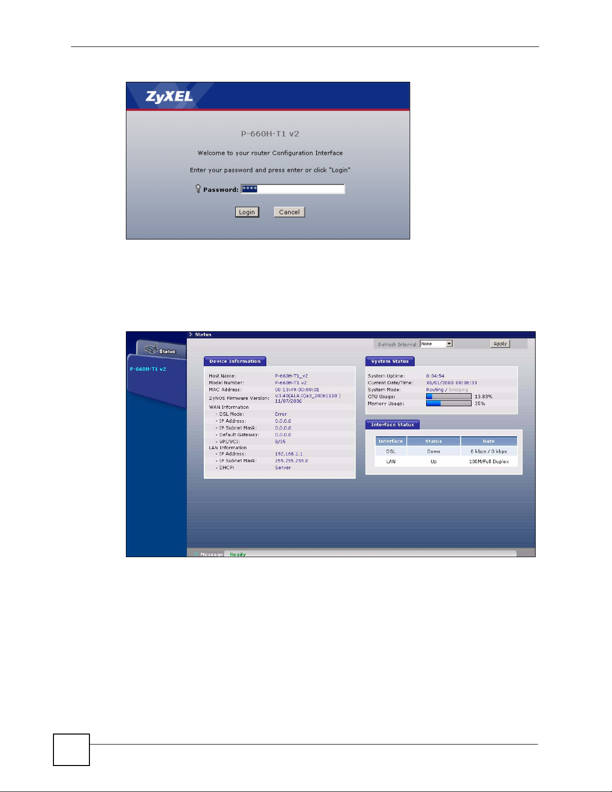
Chapter 2 Introducing the Web Configurator
Figure 6 Password Screen
2.2.1 User Access
1 For user access enter the default user password user to view the status only. The
following screen appears.
Figure 7 User status screen
2.2.2 Administrator Access
1 For administrator access enter the default admin password 1234 to configure the wizards
and the advanced features.
2 Click Login to proceed to a screen asking you to change your password or click Cancel
to revert to the default password.
3 If you entered the admin password, it is highly recommended you change the default
admin password! Enter a new password between 1 and 30 characters, retype it to
confirm and click Apply. Alternatively click Ignore to proceed to the main menu if you
do not want to change the password now.
38
P-660H-Tx v2 User’s Guide
Page 39

Chapter 2 Introducing the Web Configurator
" If you do not change the password at least once, the following screen appears
every time you log in with the admin password.
Figure 8 Change Password at Login
4 Select Go to Wizard setup and click Apply to display the wizard main screen.
Otherwise, select Go to Advanced setup and click Apply to display the Status screen.
Figure 9 Select a Mode
P-660H-Tx v2 User’s Guide
39
Page 40

Chapter 2 Introducing the Web Configurator
" The management session automatically times out when the time period set in
the Administrator Inactivity Timer field expires (default five minutes). Simply
log back into the ZyXEL Device if this happens.
2.3 Resetting the ZyXEL Device
If you forget your password or cannot access the web configurator, you will need to use the
RESET button at the back of the ZyXEL Device to reload the factory-default configuration
file. This means that you will lose all configurations that you had previously and the password
will be reset to “1234”.
2.3.1 Using the Reset Button
1 Make sure the POWER LED is on (not blinking).
2 Press the RESET button for ten seconds or until the POWER LED begins to blink and
then release it. When the POWER LED begins to blink, the defaults have been restored
and the ZyXEL Device restarts.
2.4 Navigating the Web Configurator
2.4.1 Navigation Panel
After you enter the admin password, use the sub-menus on the navigation panel to configure
ZyXEL Device features. The following table describes the sub-menus.
40
P-660H-Tx v2 User’s Guide
Page 41

Figure 10 Web Configurator: Main Screen
Use the
submenus
to configure
ZyXEL
Device
features.
Chapter 2 Introducing the Web Configurator
Click the Logout icon at any time
to exit the web configurator.
" Click the icon (located in the top right corner of most screens) to view
embedded help.
Table 3 Web Configurator Screens Summary
LINK/ICON SUB-LINK FUNCTION
Wizard INTERNET
SETUP
BANDWIDTH
MANAGEMENT
SETUP
Logout Click this icon to exit the web configurator.
Status This screen shows the ZyXEL Device’s general device, system
Network
WAN Internet
Connection
More Connections Use this screen to view and configure other connections for
WAN Backup
Setup
Use these screens for initial configuration including general
setup, ISP parameters for Internet Access and WAN IP/DNS
Server/MAC address assignment.
Use these screens to limit bandwidth usage by application or
packet type.
and interface status information. Use this screen to access the
summary statistics tables.
This screen allows you to configure ISP parameters, WAN IP
address assignment, DNS servers and other advanced
properties.
placing calls to another remote gateway.
Use this screen to configure your traffic redirect properties and
WAN backup settings.
P-660H-Tx v2 User’s Guide
41
Page 42

Chapter 2 Introducing the Web Configurator
Table 3 Web Configurator Screens Summary (continued)
LINK/ICON SUB-LINK FUNCTION
LAN IP Use this screen to configure LAN TCP/IP settings, enable Any
DHCP Setup Use this screen to configure LAN DHCP settings.
Client List
IP Alias
NAT General Use this screen to enable NAT.
Port Forwarding Use this screen to configure servers behind the ZyXEL Device.
Address Mapping Use this screen to configure network address translation
Security
Firewall General Use this screen to activate/deactivate the firewall and the
Rules This screen shows a summary of the firewall rules, and allows
Anti Probing Use this screen to change your anti-probing settings.
Threshold Use this screen to configure the threshold for DoS attacks.
Content Filter Keyword Use this screen to block sites containing certain keywords in
Schedule Use this screen to set the days and times for the ZyXEL
Trusted Use this screen to exclude a range of users on the LAN from
Advanced
Static Route Use this screen to configure IP static routes.
Bandwidth
MGMT
Dynamic DNS Use this screen to set up dynamic DNS.
Summary Use this screen to enable bandwidth management on an
Rule Setup Use this screen to define a bandwidth rule.
Monitor Use this screen to view the ZyXEL Device’s bandwidth usage
IP and other advanced properties.
Use this screen to view current DHCP client information and to
always assign an IP address to a MAC address (and host
name).
Use this screen to partition your LAN interface into subnets.
mapping rules.
direction of network traffic to which to apply the rule.
you to edit/add a firewall rule.
the URL.
Device to perform content filtering.
content filtering on your ZyXEL Device.
interface.
and allotments.
42
P-660H-Tx v2 User’s Guide
Page 43

Chapter 2 Introducing the Web Configurator
Table 3 Web Configurator Screens Summary (continued)
LINK/ICON SUB-LINK FUNCTION
Remote MGMT WWW Use this screen to configure through which interface(s) and
from which IP address(es) users can use HTTPS or HTTP to
manage the ZyXEL Device.
Te lnet Use this screen to configure through which interface(s) and
from which IP address(es) users can use Telnet to manage the
ZyXEL Device.
FTP Use this screen to configure through which interface(s) and
from which IP address(es) users can use FTP to access the
ZyXEL Device.
SNMP Use this screen to configure your ZyXEL Device’s settings for
Simple Network Management Protocol management.
DNS Use this screen to configure through which interface(s) and
ICMP Use this screen to change your anti-probing settings.
UPnP Use this screen to enable UPnP on the ZyXEL Device.
Maintenance
System General This screen contains administrative and system-related
Time Setting Use this screen to change your ZyXEL Device’s time and date.
Logs View Log Use this screen to view the logs for the categories that you
Log Settings Use this screen to change your ZyXEL Device’s log settings.
Tools Firmware Use this screen to upload firmware to your ZyXEL Device.
Configuration Use this screen to backup and restore the configuration or
Restart This screen allows you to reboot the ZyXEL Device without
Diagnostic General These screens display information to help you identify
DSL Line These screens display information to help you identify
from which IP address(es) users can send DNS queries to the
ZyXEL Device.
information and also allows you to change your password.
selected.
reset the factory defaults to your ZyXEL Device.
turning the power off.
problems with the ZyXEL Device general connection.
problems with the DSL line.
2.4.2 Status Screen
The following summarizes how to navigate the web configurator from the Status screen.
Some fields or links are not available if you entered the user password in the login password
screen (see Figure 7 on page 38). Not all fields are available on all models.
P-660H-Tx v2 User’s Guide
43
Page 44

Chapter 2 Introducing the Web Configurator
Figure 11 Status Screen
The following table describes the labels shown in the Status screen.
Table 4 Status Screen
LABEL DESCRIPTION
Refresh Interval Select a number of seconds or None from the drop-down list box to refresh all
screen statistics automatically at the end of every time interval or to not refresh the
screen statistics.
Apply Click this button to refresh the status screen statistics.
Device Information
Host Name This is the System Name you enter in the Maintenance > System > General
Model Number This is your ZyXEL Device’s model name.
MAC Address This is the MAC (Media Access Control) or Ethernet address unique to your
ZyNOS Firmware
Ver si on
WAN Information
DSL Mode This is the standard that your ZyXEL Device is using.
IP Address
IP Subnet Mask
Default Gateway This is the IP address of the default gateway, if applicable.
VPI/VCI This is the Virtual Path Identifier and Virtual Channel Identifier that you entered in
LAN Information
IP Address This is the LAN port IP address.
IP Subnet Mask This is the LAN port IP subnet mask.
screen. It is for identification purposes.
ZyXEL Device.
This is the ZyNOS Firmware version and the date created. ZyNOS is ZyXEL's
proprietary Network Operating System design.
This is the WAN port IP address.
This is the WAN port IP subnet mask.
the wizard or WAN screen.
44
P-660H-Tx v2 User’s Guide
Page 45

Chapter 2 Introducing the Web Configurator
Table 4 Status Screen
LABEL DESCRIPTION
DHCP This is the WAN port DHCP role - Server, Relay or None.
Security
Firewall This displays whether or not the ZyXEL Device’s firewall is activated.
Content Filter This displays whether or not the ZyXEL Device’s content filtering is activated.
System Status
System Uptime This is the total time the ZyXEL Device has been on.
Current Date/
Time
System Mode This displays whether the ZyXEL Device is functioning as a router or a bridge.
CPU Usage This number shows how many kilobytes of the heap memory the ZyXEL Device is
Memory Usage This number shows the ZyXEL Device's total heap memory (in kilobytes).
Interface Status
Interface This displays the ZyXEL Device port types.
Status This field displays Down (line is down), Up (line is up or connected) if you're using
Rate For the LAN ports, this displays the port speed and duplex setting.
Summary
Any IP Table Use this screen to view a list of IP addresses and MAC addresses of computers,
Bandwidth Status Use this screen to view the ZyXEL Device’s bandwidth usage and allotments.
Packet Statistics Use this screen to view port status and packet specific statistics.
This field displays your ZyXEL Device’s present date and time.
using. Heap memory refers to the memory that is not used by ZyNOS (ZyXEL
Network Operating System) and is thus available for running processes like NAT,
VPN and the firewall.
The bar displays what percent of the ZyXEL Device's heap memory is in use. The
bar turns from green to red when the maximum is being approached.
The bar displays what percent of the ZyXEL Device's heap memory is in use. The
bar turns from green to red when the maximum is being approached.
Ethernet encapsulation and Down (line is down), Up (line is up or connected), Idle
(line (ppp) idle), Dial (starting to trigger a call) and Drop (dropping a call) if you're
using PPPoE encapsulation.
Ethernet port connections can be in half-duplex or full-duplex mode. Full-duplex
refers to a device's ability to send and receive simultaneously, while half-duplex
indicates that traffic can flow in only one direction at a time. The Ethernet port
must use the same speed or duplex mode setting as the peer Ethernet port in
order to connect.
For the WAN port, it displays the downstream and upstream transmission rate.
which are not in the same subnet as the ZyXEL Device.
2.4.3 Status: Any IP Table
Click the Any IP Table hyperlink in the Status screen. The Any IP table shows current read-
only information (including the IP address and the MAC address) of all network devices that
use the Any IP feature to communicate with the ZyXEL Device.
P-660H-Tx v2 User’s Guide
45
Page 46

Chapter 2 Introducing the Web Configurator
Figure 12 Status: Any IP Table
The following table describes the labels in this screen.
Table 5 Status: Any IP Table
LABEL DESCRIPTION
# This is the index number of the host computer.
IP Address This field displays the IP address of the network device.
MAC Address This field displays the MAC (Media Access Control) address of the computer with the
displayed IP address.
Every Ethernet device has a unique MAC address. The MAC address is assigned at
the factory and consists of six pairs of hexadecimal characters, for example,
00:A0:C5:00:00:02.
Refresh Click Refresh to update this screen.
2.4.4 Status: Bandwidth Status
Click the Bandwidth Status hyperlink in the Status screen. Select an interface from the dropdown list box to view the bandwidth usage of its bandwidth rules. The gray section of the bar
represents the percentage of unused bandwidth and the blue color represents the percentage of
bandwidth in use.
Figure 13 Status: Bandwidth Status
46
P-660H-Tx v2 User’s Guide
Page 47

2.4.5 Status: Packet Statistics
Click the Packet Statistics hyperlink in the Status screen. Read-only information here
includes port status and packet specific statistics. Also provided are "system up time" and "poll
interval(s)". The Poll Interval(s) field is configurable. Not all fields are available on all
models
Figure 14 Status: Packet Statistics
Chapter 2 Introducing the Web Configurator
The following table describes the fields in this screen.
Table 6 Status: Packet Statistics
LABEL DESCRIPTION
System Monitor
System up Time This is the elapsed time the system has been up.
Current Date/Time This field displays your ZyXEL Device’s present date and time.
CPU Usage This field specifies the percentage of CPU utilization.
Memory Usage This field specifies the percentage of memory utilization.
LAN or WAN Port
Statistics
Link Status This is the status of your WAN link.
Upstream Speed This is the upstream speed of your ZyXEL Device.
Downstream Speed This is the downstream speed of your ZyXEL Device.
Node-Link This field displays the remote node index number and link type. Link types are
Interface This field displays the type of port.
This is the WAN or LAN port.
PPPoA, ENET, RFC 1483 and PPPoE.
P-660H-Tx v2 User’s Guide
47
Page 48

Chapter 2 Introducing the Web Configurator
Table 6 Status: Packet Statistics (continued)
LABEL DESCRIPTION
Status This field displays Down (line is down), Up (line is up or connected) if you're
using Ethernet encapsulation and Down (line is down), Up (line is up or
connected), Idle (line (ppp) idle), Dial (starting to trigger a call) and Drop
(dropping a call) if you're using PPPoE encapsulation.
TxPkts This field displays the number of packets transmitted on this port.
RxPkts This field displays the number of packets received on this port.
Errors This field displays the number of error packets on this port.
Tx B/s This field displays the number of bytes transmitted in the last second.
Rx B/s This field displays the number of bytes received in the last second.
Up Time This field displays the elapsed time this port has been up.
Collisions This is the number of collisions on this port.
Poll Interval(s) Type the time interval for the browser to refresh system statistics.
Set Interval Click this button to apply the new poll interval you entered in the Poll Interval
field above.
Stop Click this button to halt the refreshing of the system statistics.
2.4.6 Changing Login Password
It is highly recommended that you periodically change the password for accessing the ZyXEL
Device. If you didn’t change the default one after you logged in or you want to change to a
new password again, then click Maintenance > System to display the screen shown next. See
Table 71 on page 196 for detailed field descriptions.
Figure 15 System General
48
P-660H-Tx v2 User’s Guide
Page 49

PART II
Wizards
Wizard Setup for Internet Access (51)
Bandwidth Management Wizard (59)
49
Page 50

50
Page 51
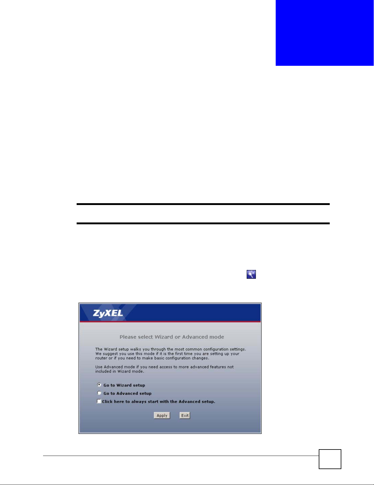
CHAPTER 3
Wizard Setup for Internet Access
This chapter provides information on the Wizard Setup screens for Internet access in the web
configurator.
3.1 Introduction
Use the wizard setup screens to configure your system for Internet access with the information
given to you by your ISP.
" See the advanced menu chapters for background information on these fields.
3.2 Internet Access Wizard Setup
1 After you enter the admin password to access the web configurator, select Go to Wizard
setup and click Apply. Otherwise, click the wizard icon ( ) in the top right corner of
the web configurator to display the wizard main screen.
Figure 16 Select a Mode
P-660H-Tx v2 User’s Guide
51
Page 52

Chapter 3 Wizard Setup for Internet Access
2 Click INTERNET SETUP to configure the system for Internet access.
Figure 17 Wizard: Welcome
3 The wizard attempts to detect which WAN connection type you are using.
If the wizard detects your connection type and your ISP uses PPPoE or PPPoA, go to
Section 3.2.1 on page 53. The screen varies depending on the connection type you use.
If the wizard does not detect a connection type and the following screen appears (see
Figure 18 on page 52), check your hardware connections and click Restart the Internet
Setup Wizard to have the ZyXEL Device detect your connection again.
Figure 18 Auto Detection: No DSL Connection
If the wizard still cannot detect a connection type and the following screen appears (see
Figure 19 on page 53), click Next and refer to Section 3.2.2 on page 53 on how to
configure the ZyXEL Device for Internet access manually.
52
P-660H-Tx v2 User’s Guide
Page 53
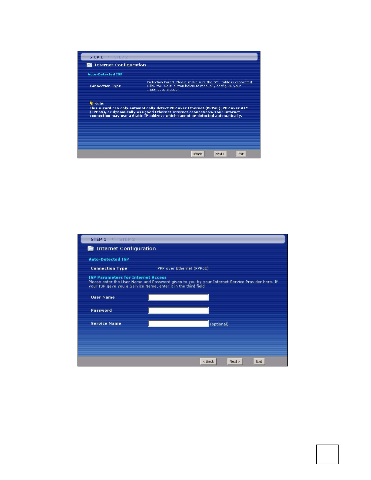
Figure 19 Auto Detection: Failed
3.2.1 Automatic Detection
1 If you have a PPPoE or PPPoA connection, a screen displays prompting you to enter
your Internet account information. Enter the username, password and/or service name
exactly as provided.
2 Click Next.
Chapter 3 Wizard Setup for Internet Access
Figure 20 Auto-Detection: PPPoE
3.2.2 Manual Configuration
1 If the ZyXEL Device fails to detect your DSL connection type, enter the Internet access
information given to you by your ISP exactly in the wizard screen. If not given, leave the
fields set to the default.
P-660H-Tx v2 User’s Guide
53
Page 54
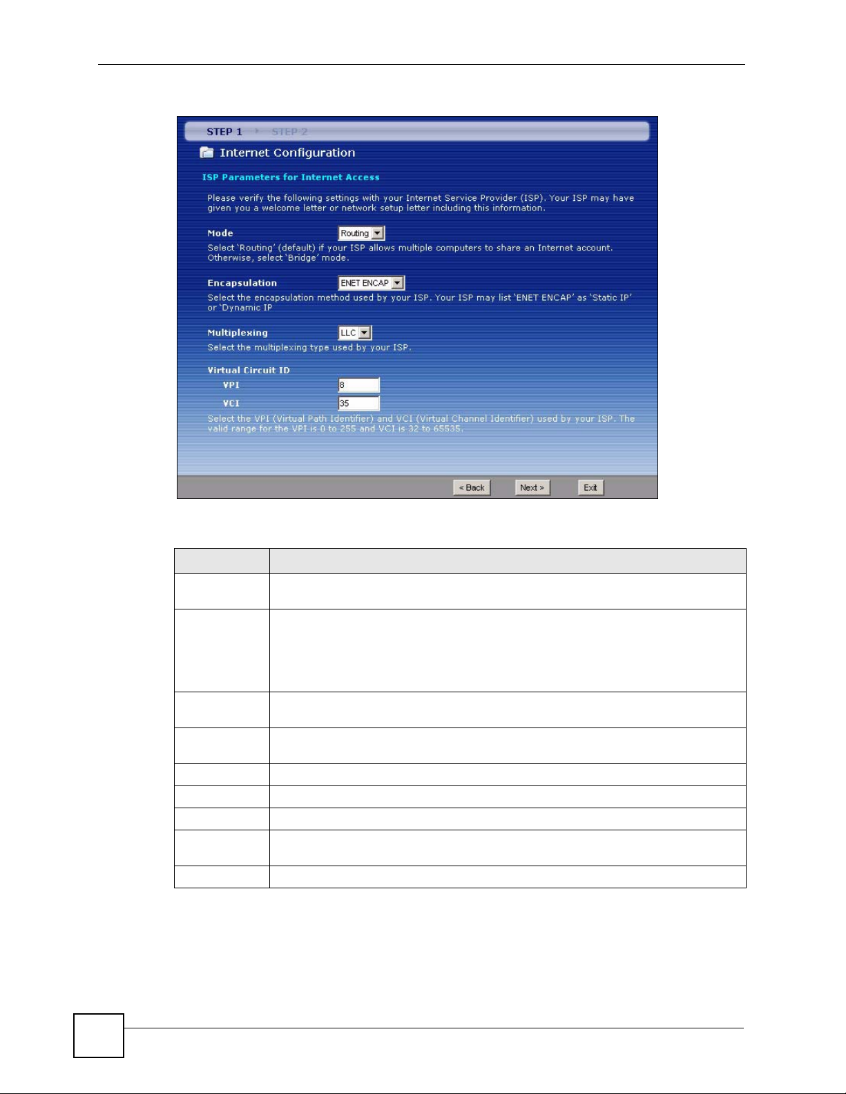
Chapter 3 Wizard Setup for Internet Access
Figure 21 Internet Access Wizard Setup: ISP Parameters
The following table describes the fields in this screen.
Table 7 Internet Access Wizard Setup: ISP Parameters
LABEL DESCRIPTION
Mode From the Mode drop-down list box, select Routing (default) if your ISP allows
Encapsulation Select the encapsulation type your ISP uses from the Encapsulation drop-down list
Multiplexing Select the multiplexing method used by your ISP from the Multiplex drop-down list
Virtual Circuit IDVPI (Virtual Path Identifier) and VCI (Virtual Channel Identifier) define a virtual circuit.
VPI Enter the VPI assigned to you. This field may already be configured.
VCI Enter the VCI assigned to you. This field may already be configured.
Back Click Back to go back to the previous screen.
Next Click Next to continue to the next wizard screen. The next wizard screen you see
Exit Click Exit to close the wizard screen without saving your changes.
multiple computers to share an Internet account. Otherwise select Bridge.
box. Choices vary depending on what you select in the Mode field.
If you select Bridge in the Mode field, select either PPPoA or RFC 1483.
If you select Routing in the Mode field, select PPPoA, RFC 1483, ENET ENCAP or
PPPoE.
box either VC-based or LLC-based.
Refer to the appendix for more information.
depends on what protocol you chose above.
2 The next wizard screen varies depending on what mode and encapsulation type you use.
All screens shown are with routing mode. Configure the fields and click Next to
continue.
54
P-660H-Tx v2 User’s Guide
Page 55

Chapter 3 Wizard Setup for Internet Access
Figure 22 Internet Connection with PPPoE
The following table describes the fields in this screen.
Table 8 Internet Connection with PPPoE
LABEL DESCRIPTION
User Name Enter the user name exactly as your ISP assigned. If assigned a name in the form
user@domain where domain identifies a service name, then enter both components
exactly as given.
Password Enter the password associated with the user name above.
Service Name Type the name of your PPPoE service here.
Back Click Back to go back to the previous wizard screen.
Apply Click Apply to save your changes to the ZyXEL Device.
Exit Click Exit to close the wizard screen without saving your changes.
Figure 23 Internet Connection with RFC 1483
The following table describes the fields in this screen.
Table 9 Internet Connection with RFC 1483
LABEL DESCRIPTION
IP Address This field is available if you select Routing in the Mode field.
Back Click Back to go back to the previous wizard screen.
P-660H-Tx v2 User’s Guide
Type your ISP assigned IP address in this field.
55
Page 56
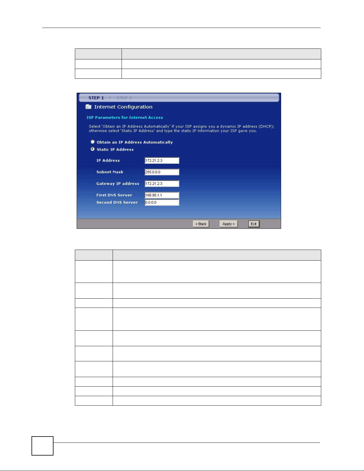
Chapter 3 Wizard Setup for Internet Access
Table 9 Internet Connection with RFC 1483 (continued)
LABEL DESCRIPTION
Next Click Next to continue to the next wizard screen.
Exit Click Exit to close the wizard screen without saving your changes.
Figure 24 Internet Connection with ENET ENCAP
The following table describes the fields in this screen.
Table 10 Internet Connection with ENET ENCAP
LABEL DESCRIPTION
Obtain an IP
Address
Automatically
Static IP
Address
IP Address Enter your ISP assigned IP address.
Subnet Mask Enter a subnet mask in dotted decimal notation.
Gateway IP
address
First DNS
Server
Second DNS
Server
Back Click Back to go back to the previous wizard screen.
Apply Click Apply to save your changes to the ZyXEL Device.
Exit Click Exit to close the wizard screen without saving your changes.
A static IP address is a fixed IP that your ISP gives you. A dynamic IP address is not
fixed; the ISP assigns you a different one each time you connect to the Internet.
Select Obtain an IP Address Automatically if you have a dynamic IP address.
Select Static IP Address if your ISP gives you a fixed IP address.
Refer to the appendices to calculate a subnet mask If you are implementing
subnetting.
You must specify a gateway IP address (supplied by your ISP) when you use ENET
ENCAP in the Encapsulation field in the previous screen.
Enter the IP addresses of the DNS servers. The DNS servers are passed to the DHCP
clients along with the IP address and the subnet mask.
As above.
56
P-660H-Tx v2 User’s Guide
Page 57
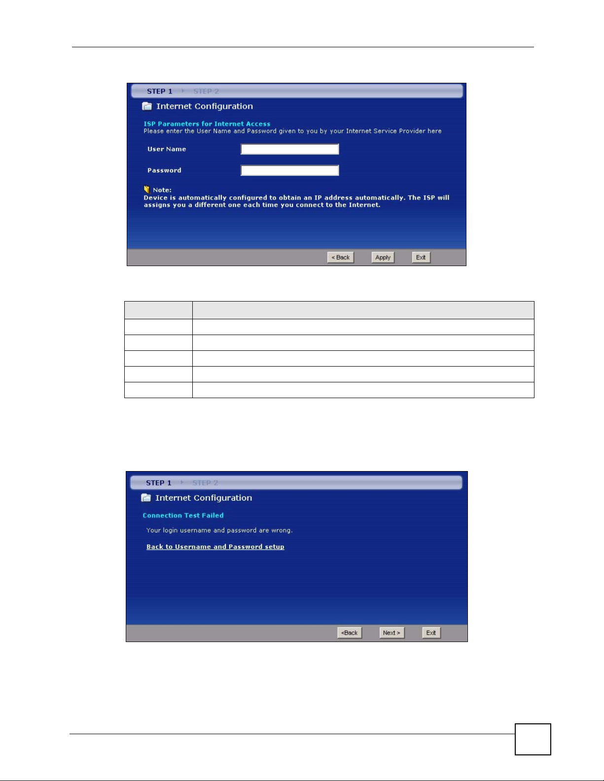
Chapter 3 Wizard Setup for Internet Access
Figure 25 Internet Connection with PPPoA
The following table describes the fields in this screen.
Tabl e 11 Internet Connection with PPPoA
LABEL DESCRIPTION
User Name Enter the login name that your ISP gives you.
Password Enter the password associated with the user name above.
Back Click Back to go back to the previous wizard screen.
Apply Click Apply to save your changes to the ZyXEL Device.
Exit Click Exit to close the wizard screen without saving your changes.
• If the user name and/or password you entered for PPPoE or PPPoA connection are not
correct, the screen displays as shown next. Click Back to Username and Password setup
to go back to the screen where you can modify them.
Figure 26 Connection Test Failed-1
• If the following screen displays, check if your account is activated or click Restart the
Internet Setup Wizard to verify your Internet access settings.
P-660H-Tx v2 User’s Guide
57
Page 58

Chapter 3 Wizard Setup for Internet Access
Figure 27 Connection Test Failed-2.
58
P-660H-Tx v2 User’s Guide
Page 59

CHAPTER 4
Bandwidth Management Wizard
This chapter shows you how to configure basic bandwidth management using the wizard
screens.
4.1 Introduction
Bandwidth management allows you to control the amount of bandwidth going out through the
ZyXEL Device’s WAN port and prioritize the distribution of the bandwidth according to
service bandwidth requirements. This helps keep one service from using all of the available
bandwidth and shutting out other users.
4.2 Predefined Media Bandwidth Management Services
The following is a description of the services that you can select and to which you can apply
media bandwidth management using the wizard screens.
Table 12 Media Bandwidth Management Setup: Services
SERVICE DESCRIPTION
E-Mail Electronic mail consists of messages sent through a computer network to specific
groups or individuals. Here are some default ports for e-mail:
POP3 - port 110
IMAP - port 143
SMTP - port 25
HTTP - port 80
FTP File Transfer Protocol enables fast transfer of files, including large files that may
not be possible by e-mail. FTP uses port number 21.
NetMeeting
(H.323)
VoIP (H.323) Sending voice signals over the Internet is called Voice over IP or VoIP.
A multimedia communications product from Microsoft that enables groups to
teleconference and videoconference over the Internet. NetMeeting supports VoIP,
text chat sessions, a whiteboard, file transfers and application sharing.
NetMeeting uses H.323. H.323 is a standard teleconferencing protocol suite that
provides audio, data and video conferencing. It allows for real-time point-to-point
and multipoint communication between client computers over a packet-based
network that does not provide a guaranteed quality of service.
H.323 is transported primarily over TCP, using the default port number 1720.
H.323 is a standard teleconferencing protocol suite that provides audio, data and
video conferencing. It allows for real-time point-to-point and multipoint
communication between client computers over a packet-based network that does
not provide a guaranteed quality of service.
H.323 is transported primarily over TCP, using the default port number 1720.
P-660H-Tx v2 User’s Guide
59
Page 60

Chapter 4 Bandwidth Management Wizard
Table 12 Media Bandwidth Management Setup: Services (continued)
SERVICE DESCRIPTION
VoIP (SIP) Sending voice signals over the Internet is called Voice over IP or VoIP. Session
Initiated Protocol (SIP) is an internationally recognized standard for implementing
VoIP. SIP is an application-layer control (signaling) protocol that handles the
setting up, altering and tearing down of voice and multimedia sessions over the
Internet.
SIP is transported primarily over UDP but can also be transported over TCP,
using the default port number 5060.
Telnet Telnet is the login and terminal emulation protocol common on the Internet and in
UNIX environments. It operates over TCP/IP networks. Its primary function is to
allow users to log into remote host systems. Telnet uses TCP port 23.
TFTP Trivial File Transfer Protocol is an Internet file transfer protocol similar to FTP, but
uses the UDP (User Datagram Protocol) rather than TCP (Transmission Control
Protocol).
WWW The World Wide Web (WWW) is an Internet system to distribute graphical, hyper-
linked information, based on Hyper Text Transfer Protocol (HTTP) - a client/server
protocol for the World Wide Web. The Web is not synonymous with the Internet;
rather, it is just one service on the Internet. Other services on the Internet include
Internet Relay Chat and Newsgroups. The Web is accessed through use of a
browser.
4.3 Bandwidth Management Wizard Setup
1 After you enter the admin password to access the web configurator, select Go to Wizard
setup and click Apply. Otherwise, click the wizard icon ( ) in the top right corner of
the web configurator to display the wizard main screen.
Figure 28 Select a Mode
60
2 Click BANDWIDTH MANAGEMENT SETUP to configure the system for Internet
access.
P-660H-Tx v2 User’s Guide
Page 61

Chapter 4 Bandwidth Management Wizard
Figure 29 Wizard: Welcome
3 Activate bandwidth management and select to allocate bandwidth to packets based on
the service requirements.
Figure 30 Bandwidth Management Wizard: General Information
The following fields describe the label in this screen.
Table 13 Bandwidth Management Wizard: General Information
LABEL DESCRIPTION
Active Select the Active check box to have the ZyXEL Device apply bandwidth
Back Click Back to display the previous screen.
Next Click Next to proceed to the next screen.
Exit Click Exit to close the wizard screen without saving.
4 Use the second wizard screen to select the services that you want to apply bandwidth
management and select the priorities that you want to apply to the services listed.
P-660H-Tx v2 User’s Guide
management to traffic going out through the ZyXEL Device’s port(s).
Select Services Setup to allocate bandwidth based on the service requirements.
61
Page 62

Chapter 4 Bandwidth Management Wizard
Figure 31 Bandwidth Management Wizard: Configuration
The following table describes the labels in this screen.
Table 14 Bandwidth Management Wizard: Configuration
LABEL DESCRIPTION
Active Select an entry’s Active check box to turn on bandwidth management for the service/
Service These fields display the services names.
Priority Select High, Mid or Low priority for each service to have your ZyXEL Device use a
Back Click Back to go back to the previous wizard screen.
Apply Click Apply to save your changes to the ZyXEL Device.
Exit Click Exit to close the wizard screen without saving your changes.
application.
priority for traffic that matches that service.
A service with High priority is given as much bandwidth as it needs.
If you select services as having the same priority, then bandwidth is divided equally
amongst those services.
Services not specified in bandwidth management are allocated bandwidth after all
specified services receive their bandwidth requirements.
If the rules set up in this wizard are changed in Advanced > Bandwidth MGMT >
Rule Setup, then the service priority radio button will be set to User Configured.
The Advanced > Bandwidth MGMT > Rule Setup screen allows you to edit these
rule configurations.
5 Follow the on-screen instructions and click Finish to complete the wizard setup and save
your configuration.
62
P-660H-Tx v2 User’s Guide
Page 63

Chapter 4 Bandwidth Management Wizard
Figure 32 Bandwidth Management Wizard: Complete
P-660H-Tx v2 User’s Guide
63
Page 64

Chapter 4 Bandwidth Management Wizard
64
P-660H-Tx v2 User’s Guide
Page 65

PART III
Network
WA N S e t u p ( 6 7 )
LAN Setup (85)
Network Address Translation (NAT) Screens (97)
65
Page 66

66
Page 67

CHAPTER 5
WAN Setup
This chapter describes how to configure WAN settings.
5.1 WAN Overview
A WAN (Wide Area Network) is an outside connection to another network or the Internet.
5.1.1 Encapsulation
Be sure to use the encapsulation method required by your ISP. The ZyXEL Device supports
the following methods.
5.1.1.1 ENET ENCAP
The MAC Encapsulated Routing Link Protocol (ENET ENCAP) is only implemented with the
IP network protocol. IP packets are routed between the Ethernet interface and the WAN
interface and then formatted so that they can be understood in a bridged environment. For
instance, it encapsulates routed Ethernet frames into bridged ATM cells. ENET ENCAP
requires that you specify a gateway IP address in the ENET ENCAP Gateway field in the
second wizard screen. You can get this information from your ISP.
5.1.1.2 PPP over Ethernet
PPPoE (Point-to-Point Protocol over Ethernet) provides access control and billing
functionality in a manner similar to dial-up services using PPP. PPPoE is an IETF standard
(RFC 2516) specifying how a personal computer (PC) interacts with a broadband modem
(DSL, cable, etc.) connection.
For the service provider, PPPoE offers an access and authentication method that works with
existing access control systems (for example RADIUS).
One of the benefits of PPPoE is the ability to let you access one of multiple network services,
a function known as dynamic service selection. This enables the service provider to easily
create and offer new IP services for individuals.
Operationally, PPPoE saves significant effort for both you and the ISP or carrier, as it requires
no specific configuration of the broadband modem at the customer site.
By implementing PPPoE directly on the ZyXEL Device (rather than individual computers),
the computers on the LAN do not need PPPoE software installed, since the ZyXEL Device
does that part of the task. Furthermore, with NAT, all of the LANs’ computers will have
access.
P-660H-Tx v2 User’s Guide
67
Page 68

Chapter 5 WAN Setup
5.1.1.3 PPPoA
PPPoA stands for Point to Point Protocol over ATM Adaptation Layer 5 (AAL5). A PPPoA
connection functions like a dial-up Internet connection. The ZyXEL Device encapsulates the
PPP session based on RFC1483 and sends it through an ATM PVC (Permanent Virtual
Circuit) to the Internet Service Provider’s (ISP) DSLAM (digital access multiplexer). Please
refer to RFC 2364 for more information on PPPoA. Refer to RFC 1661 for more information
on PPP.
5.1.1.4 RFC 1483
RFC 1483 describes two methods for Multiprotocol Encapsulation over ATM Adaptation
Layer 5 (AAL5). The first method allows multiplexing of multiple protocols over a single
ATM virtual circuit (LLC-based multiplexing) and the second method assumes that each
protocol is carried over a separate ATM virtual circuit (VC-based multiplexing). Please refer
to the RFC for more detailed information.
5.1.2 Multiplexing
There are two conventions to identify what protocols the virtual circuit (VC) is carrying. Be
sure to use the multiplexing method required by your ISP.
5.1.2.1 VC-based Multiplexing
In this case, by prior mutual agreement, each protocol is assigned to a specific virtual circuit;
for example, VC1 carries IP, etc. VC-based multiplexing may be dominant in environments
where dynamic creation of large numbers of ATM VCs is fast and economical.
5.1.2.2 LLC-based Multiplexing
In this case one VC carries multiple protocols with protocol identifying information being
contained in each packet header. Despite the extra bandwidth and processing overhead, this
method may be advantageous if it is not practical to have a separate VC for each carried
protocol, for example, if charging heavily depends on the number of simultaneous VCs.
5.1.3 Encapsulation and Multiplexing Scenarios
For Internet access you should use the encapsulation and multiplexing methods used by your
ISP. Consult your telephone company for information on encapsulation and multiplexing
methods for LAN-to-LAN applications, for example between a branch office and corporate
headquarters. There must be prior agreement on encapsulation and multiplexing methods
because they cannot be automatically determined. What method(s) you use also depends on
how many VCs you have and how many different network protocols you need. The extra
overhead that ENET ENCAP encapsulation entails makes it a poor choice in a LAN-to-LAN
application. Here are some examples of more suitable combinations in such an application.
5.1.3.1 Scenario 1: One VC, Multiple Protocols
PPPoA (RFC-2364) encapsulation with VC-based multiplexing is the best combination
because no extra protocol identifying headers are needed. The PPP protocol already contains
this information.
68
P-660H-Tx v2 User’s Guide
Page 69

5.1.3.2 Scenario 2: One VC, One Protocol (IP)
Selecting RFC-1483 encapsulation with VC-based multiplexing requires the least amount of
overhead (0 octets). However, if there is a potential need for multiple protocol support in the
future, it may be safer to select PPPoA encapsulation instead of RFC-1483, so you do not
need to reconfigure either computer later.
5.1.3.3 Scenario 3: Multiple VCs
If you have an equal number (or more) of VCs than the number of protocols, then select RFC1483 encapsulation and VC-based multiplexing.
5.1.4 VPI and VCI
Be sure to use the correct Virtual Path Identifier (VPI) and Virtual Channel Identifier (VCI)
numbers assigned to you. The valid range for the VPI is 0 to 255 and for the VCI is 32 to
65535 (0 to 31 is reserved for local management of ATM traffic). Please see the appendix for
more information.
5.1.5 IP Address Assignment
Chapter 5 WAN Setup
A static IP is a fixed IP that your ISP gives you. A dynamic IP is not fixed; the ISP assigns you
a different one each time. The Single User Account feature can be enabled or disabled if you
have either a dynamic or static IP. However the encapsulation method assigned influences
your choices for IP address and ENET ENCAP gateway.
5.1.5.1 IP Assignment with PPPoA or PPPoE Encapsulation
If you have a dynamic IP, then the IP Address and ENET ENCAP Gateway fields are not
applicable (N/A). If you have a static IP, then you only need to fill in the IP Address field and
not the ENET ENCAP Gateway field.
5.1.5.2 IP Assignment with RFC 1483 Encapsulation
In this case the IP Address Assignment must be static with the same requirements for the IP
Address and ENET ENCAP Gateway fields as stated above.
5.1.5.3 IP Assignment with ENET ENCAP Encapsulation
In this case you can have either a static or dynamic IP. For a static IP you must fill in all the IP
Address and ENET ENCAP Gateway fields as supplied by your ISP. However for a
dynamic IP, the ZyXEL Device acts as a DHCP client on the WAN port and so the IP
Address and ENET ENCAP Gateway fields are not applicable (N/A) as the DHCP server
assigns them to the ZyXEL Device.
5.1.6 Nailed-Up Connection (PPP)
A nailed-up connection is a dial-up line where the connection is always up regardless of traffic
demand. The ZyXEL Device does two things when you specify a nailed-up connection. The
first is that idle timeout is disabled. The second is that the ZyXEL Device will try to bring up
the connection when turned on and whenever the connection is down. A nailed-up connection
can be very expensive for obvious reasons.
P-660H-Tx v2 User’s Guide
69
Page 70

Chapter 5 WAN Setup
Do not specify a nailed-up connection unless your telephone company offers flat-rate service
or you need a constant connection and the cost is of no concern
5.1.7 NAT
NAT (Network Address Translation - NAT, RFC 1631) is the translation of the IP address of a
host in a packet, for example, the source address of an outgoing packet, used within one
network to a different IP address known within another network.
5.2 Metric
The metric represents the "cost of transmission". A router determines the best route for
transmission by choosing a path with the lowest "cost". RIP routing uses hop count as the
measurement of cost, with a minimum of "1" for directly connected networks. The number
must be between "1" and "15"; a number greater than "15" means the link is down. The
smaller the number, the lower the "cost".
The metric sets the priority for the ZyXEL Device’s routes to the Internet. If any two of the
default routes have the same metric, the ZyXEL Device uses the following pre-defined
priorities:
• Normal route: designated by the ISP (see Section 5.5 on page 72)
• Traffic-redirect route (see Section 5.7 on page 81)
• WAN-backup route, also called dial-backup (see Section 5.8 on page 82)
For example, if the normal route has a metric of "1" and the traffic-redirect route has a metric
of "2" and dial-backup route has a metric of "3", then the normal route acts as the primary
default route. If the normal route fails to connect to the Internet, the ZyXEL Device tries the
traffic-redirect route next. In the same manner, the ZyXEL Device uses the dial-backup route
if the traffic-redirect route also fails.
If you want the dial-backup route to take first priority over the traffic-redirect route or even the
normal route, all you need to do is set the dial-backup route’s metric to "1" and the others to
"2" (or greater).
IP Policy Routing overrides the default routing behavior and takes priority over all of the
routes mentioned above.
5.3 Traffic Shaping
Traffic Shaping is an agreement between the carrier and the subscriber to regulate the average
rate and fluctuations of data transmission over an ATM network. This agreement helps
eliminate congestion, which is important for transmission of real time data such as audio and
video connections.
70
Peak Cell Rate (PCR) is the maximum rate at which the sender can send cells. This parameter
may be lower (but not higher) than the maximum line speed. 1 ATM cell is 53 bytes (424 bits),
so a maximum speed of 832Kbps gives a maximum PCR of 1962 cells/sec. This rate is not
guaranteed because it is dependent on the line speed.
P-660H-Tx v2 User’s Guide
Page 71

Chapter 5 WAN Setup
Sustained Cell Rate (SCR) is the mean cell rate of each bursty traffic source. It specifies the
maximum average rate at which cells can be sent over the virtual connection. SCR may not be
greater than the PCR.
Maximum Burst Size (MBS) is the maximum number of cells that can be sent at the PCR.
After MBS is reached, cell rates fall below SCR until cell rate averages to the SCR again. At
this time, more cells (up to the MBS) can be sent at the PCR again.
If the PCR, SCR or MBS is set to the default of "0", the system will assign a maximum value
that correlates to your upstream line rate.
The following figure illustrates the relationship between PCR, SCR and MBS.
Figure 33 Example of Traffic Shaping
5.3.1 ATM Traffic Classes
These are the basic ATM traffic classes defined by the ATM Forum Traffic Management 4.0
Specification.
5.3.1.1 Constant Bit Rate (CBR)
Constant Bit Rate (CBR) provides fixed bandwidth that is always available even if no data is
being sent. CBR traffic is generally time-sensitive (doesn't tolerate delay). CBR is used for
connections that continuously require a specific amount of bandwidth. A PCR is specified and
if traffic exceeds this rate, cells may be dropped. Examples of connections that need CBR
would be high-resolution video and voice.
5.3.1.2 Variable Bit Rate (VBR)
The Variable Bit Rate (VBR) ATM traffic class is used with bursty connections. Connections
that use the Variable Bit Rate (VBR) traffic class can be grouped into real time (VBR-RT) or
non-real time (VBR-nRT) connections.
The VBR-RT (real-time Variable Bit Rate) type is used with bursty connections that require
closely controlled delay and delay variation. It also provides a fixed amount of bandwidth (a
PCR is specified) but is only available when data is being sent. An example of an VBR-RT
connection would be video conferencing. Video conferencing requires real-time data transfers
and the bandwidth requirement varies in proportion to the video image's changing dynamics.
P-660H-Tx v2 User’s Guide
71
Page 72

Chapter 5 WAN Setup
The VBR-nRT (non real-time Variable Bit Rate) type is used with bursty connections that do
not require closely controlled delay and delay variation. It is commonly used for "bursty"
traffic typical on LANs. PCR and MBS define the burst levels, SCR defines the minimum
level. An example of an VBR-nRT connection would be non-time sensitive data file transfers.
5.3.1.3 Unspecified Bit Rate (UBR)
The Unspecified Bit Rate (UBR) ATM traffic class is for bursty data transfers. However, UBR
doesn't guarantee any bandwidth and only delivers traffic when the network has spare
bandwidth. An example application is background file transfer.
5.4 Zero Configuration Internet Access
Once you turn on and connect the ZyXEL Device to a telephone jack, it automatically detects
the Internet connection settings (such as the VCI/VPI numbers and the encapsulation method)
from the ISP and makes the necessary configuration changes. In cases where additional
account information (such as an Internet account user name and password) is required or the
ZyXEL Device cannot connect to the ISP, you will be redirected to web screen(s) for
information input or troubleshooting.
Zero configuration for Internet access is disable when
• the ZyXEL Device is in bridge mode
• you set the ZyXEL Device to use a static (fixed) WAN IP address.
5.5 Internet Connection
To change your ZyXEL Device’s WAN Internet access settings, click Network > WAN. The
screen differs by the encapsulation.
See Section 5.1 on page 67 for more information.
72
P-660H-Tx v2 User’s Guide
Page 73
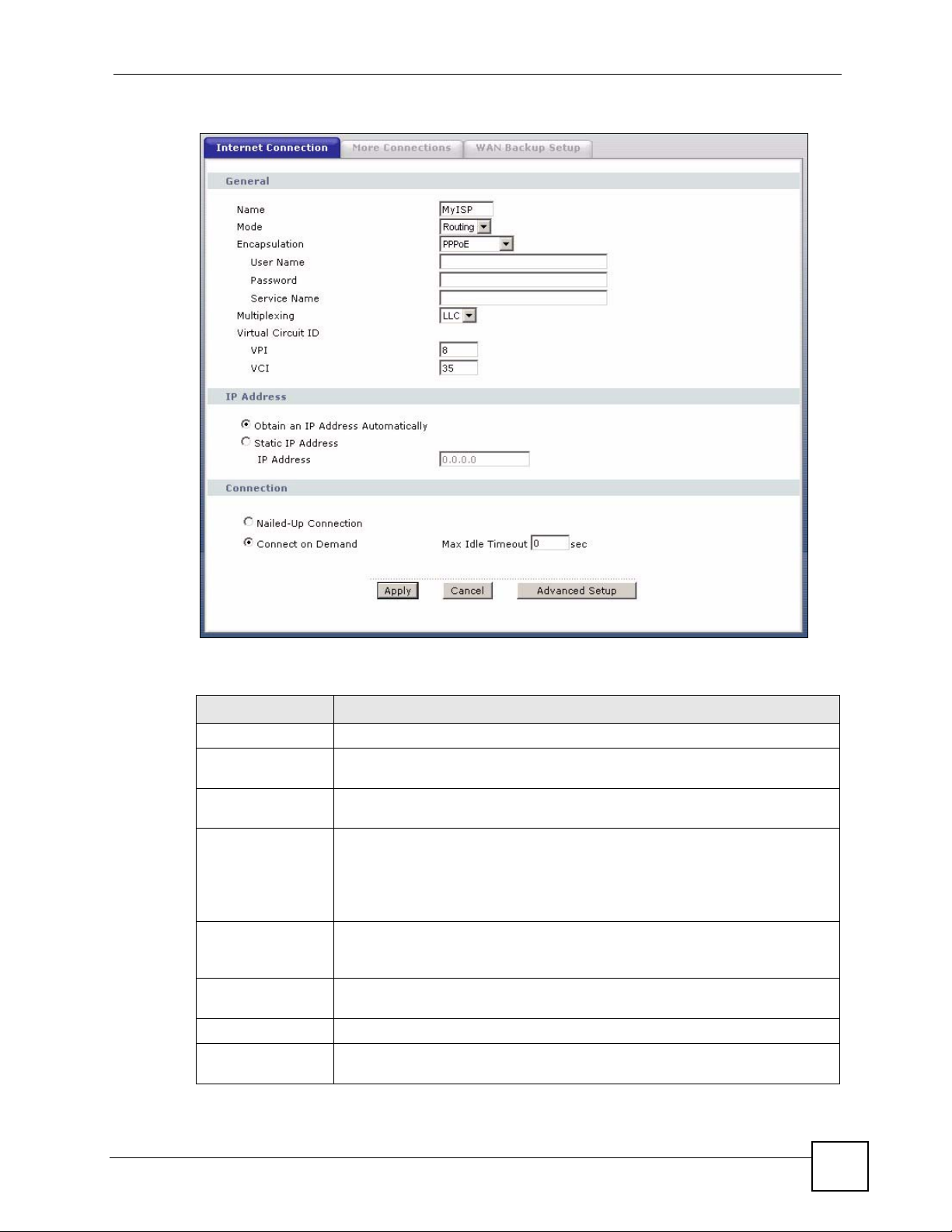
Figure 34 Internet Connection (PPPoE)
Chapter 5 WAN Setup
The following table describes the labels in this screen.
Table 15 Internet Connection
LABEL DESCRIPTION
General
Name Enter the name of your Internet Service Provider, e.g., MyISP. This information
is for identification purposes only.
Mode Select Routing (default) from the drop-down list box if your ISP allows multiple
Encapsulation Select the method of encapsulation used by your ISP from the drop-down list
User Name (PPPoA and PPPoE encapsulation only) Enter the user name exactly as your
Password (PPPoA and PPPoE encapsulation only) Enter the password associated with the
Service Name (PPPoE only) Type the name of your PPPoE service here.
Multiplexing Select the method of multiplexing used by your ISP from the drop-down list.
computers to share an Internet account. Otherwise select Bridge.
box. Choices vary depending on the mode you select in the Mode field.
If you select Bridge in the Mode field, select either PPPoA or RFC 1483.
If you select Routing in the Mode field, select PPPoA, RFC 1483, ENET
ENCAP or PPPoE.
ISP assigned. If assigned a name in the form user@domain where domain
identifies a service name, then enter both components exactly as given.
user name above.
Choices are VC or LLC.
P-660H-Tx v2 User’s Guide
73
Page 74

Chapter 5 WAN Setup
Table 15 Internet Connection (continued)
LABEL DESCRIPTION
Virtual Circuit ID VPI (Virtual Path Identifier) and VCI (Virtual Channel Identifier) define a virtual
VPI The valid range for the VPI is 0 to 255. Enter the VPI assigned to you.
VCI The valid range for the VCI is 32 to 65535 (0 to 31 is reserved for local
IP Address This option is available if you select Routing in the Mode field.
Subnet Mask
(ENET ENCAP
encapsulation only)
Gateway IP address
(ENET ENCAP
encapsulation only)
Connection
(PPPoA and PPPoE
encapsulation only)
Nailed-Up
Connection
Connect on
Demand
Max Idle Timeout Specify an idle time-out in the Max Idle Timeout field when you select Connect
Apply Click Apply to save the changes.
Cancel Click Cancel to begin configuring this screen afresh.
Advanced Setup Click this button to display the Advanced Internet Connection Setup screen
circuit. Refer to the appendix for more information.
management of ATM traffic). Enter the VCI assigned to you.
A static IP address is a fixed IP that your ISP gives you. A dynamic IP address is
not fixed; the ISP assigns you a different one each time you connect to the
Internet.
If you use the encapsulation type except RFC 1483, select Obtain an IP
Address Automatically when you have a dynamic IP address; otherwise select
Static IP Address and type your ISP assigned IP address in the IP Address
field below.
If you use RFC 1483, enter the IP address given by your ISP in the IP Address
field.
Enter a subnet mask in dotted decimal notation.
Refer to the appendices to calculate a subnet mask If you are implementing
subnetting.
You must specify a gateway IP address (supplied by your ISP) when you select
ENET ENCAP in the Encapsulation field
Select Nailed-Up Connection when you want your connection up all the time.
The ZyXEL Device will try to bring up the connection automatically if it is
disconnected.
Select Connect on Demand when you don't want the connection up all the time
and specify an idle time-out in the Max Idle Timeout field.
on Demand. The default setting is 0, which means the Internet session will not
timeout.
and edit more details of your WAN setup.
5.5.1 Configuring Advanced Internet Connection Setup
To edit your ZyXEL Device's advanced WAN settings, click the Advanced Setup button in
the Internet Connection screen. The screen appears as shown.
74
P-660H-Tx v2 User’s Guide
Page 75

Figure 35 Advanced Internet Connection Setup
Chapter 5 WAN Setup
The following table describes the labels in this screen.
Table 16 Advanced Internet Connection Setup
LABEL DESCRIPTION
RIP & Multicast
Setup
RIP Direction Select the RIP direction from None, Both, In Only and Out Only.
RIP Version Select the RIP version from RIP-1, RIP-2B and RIP-2M.
Multicast IGMP (Internet Group Multicast Protocol) is a network-layer protocol used to
establish membership in a multicast group. The ZyXEL Device supports both IGMP
version 1 (IGMP-v1) and IGMP-v2. Select None to disable it.
ATM Q oS
ATM QoS Type Select CBR (Continuous Bit Rate) to specify fixed (always-on) bandwidth for voice
or data traffic. Select UBR (Unspecified Bit Rate) for applications that are non-time
sensitive, such as e-mail. Select VBR-nRT (Variable Bit Rate-non Real Time) or
VBR-RT (Variable Bit Rate-Real Time) for bursty traffic and bandwidth sharing with
other applications.
Peak Cell Rate Divide the DSL line rate (bps) by 424 (the size of an ATM cell) to find the Peak Cell
Rate (PCR). This is the maximum rate at which the sender can send cells. Type the
PCR here.
Sustain Cell Rate The Sustain Cell Rate (SCR) sets the average cell rate (long-term) that can be
transmitted. Type the SCR, which must be less than the PCR. Note that system
default is 0 cells/sec.
Maximum Burst
Size
Maximum Burst Size (MBS) refers to the maximum number of cells that can be
sent at the peak rate. Type the MBS, which is less than 65535.
P-660H-Tx v2 User’s Guide
75
Page 76

Chapter 5 WAN Setup
Table 16 Advanced Internet Connection Setup (continued)
LABEL DESCRIPTION
Zero
Configuration
PPPoE
Passthrough
Back Click Back to return to the previous screen.
Apply Click Apply to save the changes.
Cancel Click Cancel to begin configuring this screen afresh.
This feature is not applicable/available when you configure the ZyXEL Device to
use a static WAN IP address or in bridge mode.
Select Yes to set the ZyXEL Device to automatically detect the Internet connection
settings (such as the VCI/VPI numbers and the encapsulation method) from the
ISP and make the necessary configuration changes.
Select No to disable this feature. You must manually configure the ZyXEL Device
for Internet access.
This feature is available when you select PPPoE encapsulation.
In addition to the ZyXEL Device's built-in PPPoE client, you can enable PPPoE
pass through to allow up to ten hosts on the LAN to use PPPoE client software on
their computers to connect to the ISP via the ZyXEL Device. Each host can have a
separate account and a public WAN IP address.
PPPoE pass through is an alternative to NAT for application where NAT is not
appropriate.
Disable PPPoE pass through if you do not need to allow hosts on the LAN to use
PPPoE client software on their computers to connect to the ISP.
5.6 Configuring More Connections
This section describes the protocol-independent parameters for a remote network. They are
required for placing calls to a remote gateway and the network behind it across a WAN
connection. When you use the WAN > Internet Connection screen to set up Internet access,
you are configuring the first WAN connection.
Click Network > WAN > More Connections to display the screen as shown next.
Figure 36 More Connections
76
P-660H-Tx v2 User’s Guide
Page 77

The following table describes the labels in this screen.
Table 17 More Connections
LABEL DESCRIPTION
# This is the index number of a connection.
Active This display whether this connection is activated. Clear the check box to disable
the connection. Select the check box to enable it.
Name This is the descriptive name for this connection.
VPI/VCI This is the VPI and VCI values used for this connection.
Encapsulation This is the method of encapsulation used for this connection.
Modify The first (ISP) connection is read-only in this screen. Use the WAN > Internet
Connection screen to edit it.
Click the edit icon to go to the screen where you can edit the connection.
Click the delete icon to remove an existing connection. You cannot remove the
first connection.
Apply Click Apply to save the changes.
Cancel Click Cancel to begin configuring this screen afresh.
5.6.1 More Connections Edit
Chapter 5 WAN Setup
Click the edit icon in the More Connections screen to configure a connection.
P-660H-Tx v2 User’s Guide
77
Page 78

Chapter 5 WAN Setup
Figure 37 More Connections Edit
78
The following table describes the labels in this screen.
Table 18 More Connections Edit
LABEL DESCRIPTION
Active Select the check box to activate or clear the check box to deactivate this
connection.
Name Enter a unique, descriptive name of up to 13 ASCII characters for this
connection.
Mode Select Routing from the drop-down list box if your ISP allows multiple
computers to share an Internet account.
If you select Bridge, the ZyXEL Device will forward any packet that it does not
route to this remote node; otherwise, the packets are discarded.
Encapsulation Select the method of encapsulation used by your ISP from the drop-down list
box. Choices are PPPoA, RFC 1483, ENET ENCAP or PPPoE.
P-660H-Tx v2 User’s Guide
Page 79

Chapter 5 WAN Setup
Table 18 More Connections Edit (continued)
LABEL DESCRIPTION
User Name (PPPoA and PPPoE encapsulation only) Enter the user name exactly as your
ISP assigned. If assigned a name in the form user@domain where domain
identifies a service name, then enter both components exactly as given.
Password (PPPoA and PPPoE encapsulation only) Enter the password associated with the
user name above.
Service Name (PPPoE only) Type the name of your PPPoE service here.
Multiplexing Select the method of multiplexing used by your ISP from the drop-down list.
Choices are VC or LLC.
By prior agreement, a protocol is assigned a specific virtual circuit, for example,
VC1 will carry IP. If you select VC, specify separate VPI and VCI numbers for
each protocol.
For LLC-based multiplexing or PPP encapsulation, one VC carries multiple
protocols with protocol identifying information being contained in each packet
header. In this case, only one set of VPI and VCI numbers need be specified for
all protocols.
VPI The valid range for the VPI is 0 to 255. Enter the VPI assigned to you.
VCI The valid range for the VCI is 32 to 65535 (0 to 31 is reserved for local
IP Address This option is available if you select Routing in the Mode field.
Subnet Mask Enter a subnet mask in dotted decimal notation.
Gateway IP address Specify a gateway IP address (supplied by your ISP).
Connection
Nailed-Up
Connection
Connect on
Demand
Max Idle Timeout Specify an idle time-out in the Max Idle Timeout field when you select Connect
NAT NAT is the translation of the IP address of a host in a packet, for example, the
None Select None to disable NAT.
SUA Only SUA only is available only when you select Routing in the Mode field.
Back Click Back to return to the previous screen.
management of ATM traffic). Enter the VCI assigned to you.
A static IP address is a fixed IP that your ISP gives you. A dynamic IP address is
not fixed; the ISP assigns you a different one each time you connect to the
Internet.
If you use the encapsulation type except RFC 1483, select Obtain an IP
Address Automatically when you have a dynamic IP address; otherwise select
Static IP Address and type your ISP assigned IP address in the IP Address
field below.
If you use RFC 1483, enter the IP address given by your ISP in the IP Address
field.
Refer to the appendices to calculate a subnet mask If you are implementing
subnetting.
Select Nailed-Up Connection when you want your connection up all the time.
The ZyXEL Device will try to bring up the connection automatically if it is
disconnected.
Select Connect on Demand when you don't want the connection up all the time
and specify an idle time-out in the Max Idle Timeout field.
on Demand. The default setting is 0, which means the Internet session will not
timeout.
source address of an outgoing packet, used within one network to a different IP
address known within another network.
Select SUA Only if you have one public IP address and want to use NAT. Click
Edit to go to the Port Forwarding screen to edit a server mapping set.
P-660H-Tx v2 User’s Guide
79
Page 80

Chapter 5 WAN Setup
Table 18 More Connections Edit (continued)
LABEL DESCRIPTION
Apply Click Apply to save the changes.
Cancel Click Cancel to begin configuring this screen afresh.
Advanced Setup Click this button to display the More Connections Advanced screen and edit
more details of your WAN setup.
5.6.2 Configuring More Connections Advanced Setup
To edit your ZyXEL Device's advanced WAN settings, click the Advanced Setup button in
the More Connections Edit screen. The screen appears as shown.
Figure 38 More Connections Advanced Setup
The following table describes the labels in this screen.
Table 19 More Connections Advanced Setup
LABEL DESCRIPTION
RIP & Multicast
Setup
RIP Direction Select the RIP direction from None, Both, In Only and Out Only.
RIP Version Select the RIP version from RIP-1, RIP-2B and RIP-2M.
Multicast IGMP (Internet Group Multicast Protocol) is a network-layer protocol used to
establish membership in a multicast group. The ZyXEL Device supports both IGMP
version 1 (IGMP-v1) and IGMP-v2. Select None to disable it.
ATM Q oS
ATM QoS Type Select CBR (Continuous Bit Rate) to specify fixed (always-on) bandwidth for voice
Peak Cell Rate Divide the DSL line rate (bps) by 424 (the size of an ATM cell) to find the Peak Cell
or data traffic. Select UBR (Unspecified Bit Rate) for applications that are non-time
sensitive, such as e-mail. Select VBR-nRT (Variable Bit Rate-non Real Time) or
VBR-RT (Variable Bit Rate-Real Time) for bursty traffic and bandwidth sharing with
other applications.
Rate (PCR). This is the maximum rate at which the sender can send cells. Type the
PCR here.
80
P-660H-Tx v2 User’s Guide
Page 81

Table 19 More Connections Advanced Setup (continued)
LABEL DESCRIPTION
Sustain Cell Rate The Sustain Cell Rate (SCR) sets the average cell rate (long-term) that can be
transmitted. Type the SCR, which must be less than the PCR. Note that system
default is 0 cells/sec.
Maximum Burst
Size
Back Click Back to return to the previous screen.
Apply Click Apply to save the changes.
Cancel Click Cancel to begin configuring this screen afresh.
Maximum Burst Size (MBS) refers to the maximum number of cells that can be
sent at the peak rate. Type the MBS, which is less than 65535.
5.7 Traffic Redirect
Traffic redirect forwards traffic to a backup gateway when the ZyXEL Device cannot connect
to the Internet. An example is shown in the figure below.
Figure 39 Traffic Redirect Example
Chapter 5 WAN Setup
The following network topology allows you to avoid triangle route security issues when the
backup gateway is connected to the LAN. Use IP alias to configure the LAN into two or three
logical networks with the ZyXEL Device itself as the gateway for each LAN network. Put the
protected LAN in one subnet (Subnet 1 in the following figure) and the backup gateway in
another subnet (Subnet 2). Configure filters that allow packets from the protected LAN
(Subnet 1) to the backup gateway (Subnet 2).
P-660H-Tx v2 User’s Guide
81
Page 82
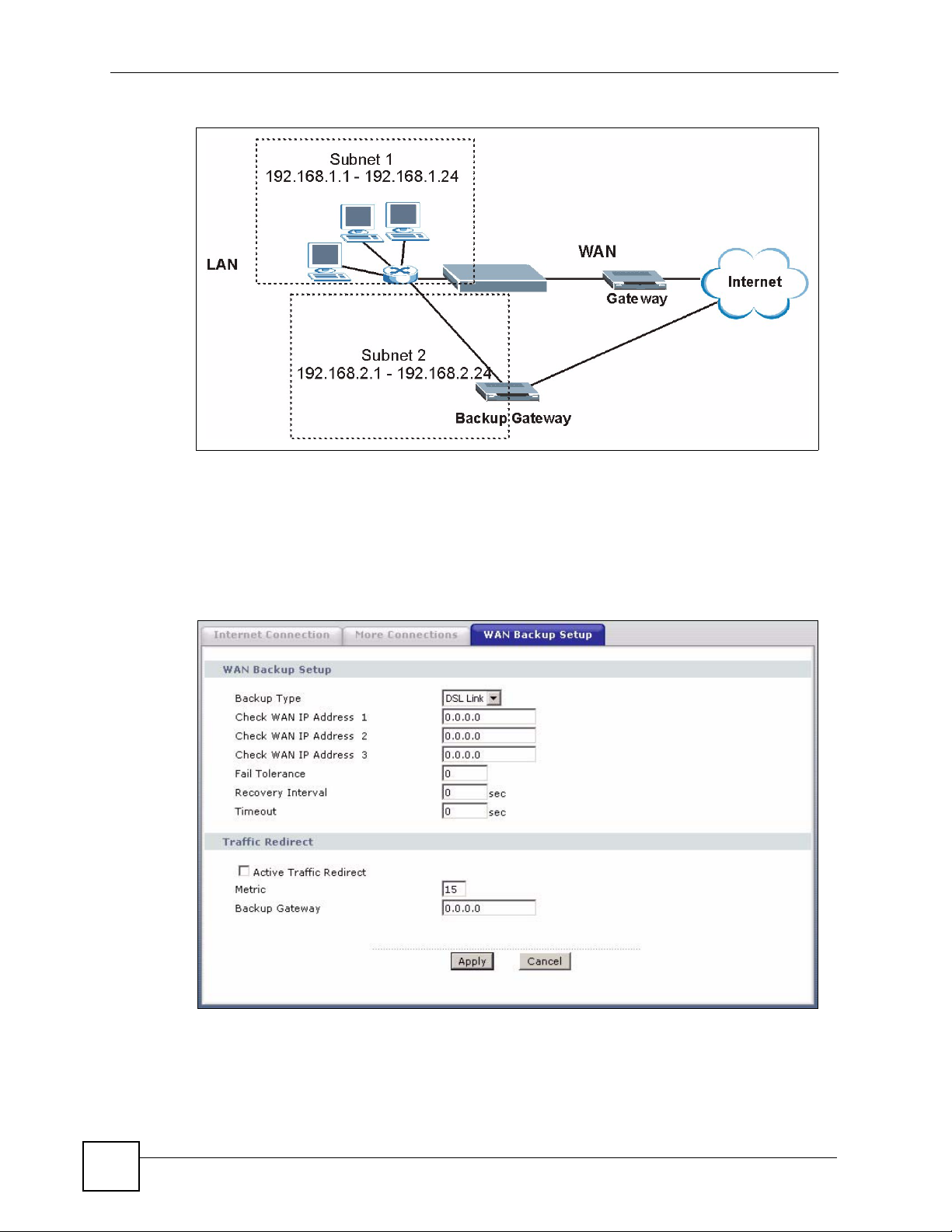
Chapter 5 WAN Setup
Figure 40 Traffic Redirect LAN Setup
5.8 Configuring WAN Backup
To change your ZyXEL Device’s WAN backup settings, click Network > WAN > WAN
Backup Setup. The screen appears as shown.
Figure 41 WAN Backup Setup
82
P-660H-Tx v2 User’s Guide
Page 83

Chapter 5 WAN Setup
The following table describes the labels in this screen.
Table 20 WAN Backup Setup
LABEL DESCRIPTION
Backup Type Select the method that the ZyXEL Device uses to check the DSL connection.
Select DSL Link to have the ZyXEL Device check if the connection to the DSLAM
is up. Select ICMP to have the ZyXEL Device periodically ping the IP addresses
configured in the Check WAN IP Address fields.
Check WAN IP
Address1-3
Configure this field to test your ZyXEL Device's WAN accessibility. Type the IP
address of a reliable nearby computer (for example, your ISP's DNS server
address).
Note: If you activate either traffic redirect or dial backup, you must
configure at least one IP address here.
When using a WAN backup connection, the ZyXEL Device periodically pings the
addresses configured here and uses the other WAN backup connection (if
configured) if there is no response.
Fail Tolerance Type the number of times (2 recommended) that your ZyXEL Device may ping the
Recovery Interval When the ZyXEL Device is using a lower priority connection (usually a WAN
Timeout Type the number of seconds (3 recommended) for your ZyXEL Device to wait for a
Traffic Redirect Traffic redirect forwards traffic to a backup gateway when the ZyXEL Device
Active Traffic
Redirect
IP addresses configured in the Check WAN IP Address field without getting a
response before switching to a WAN backup connection (or a different WAN
backup connection).
backup connection), it periodically checks to whether or not it can use a higher
priority connection.
Type the number of seconds (30 recommended) for the ZyXEL Device to wait
between checks. Allow more time if your destination IP address handles lots of
traffic.
ping response from one of the IP addresses in the Check WAN IP Address field
before timing out the request. The WAN connection is considered "down" after the
ZyXEL Device times out the number of times specified in the Fail Tolerance field.
Use a higher value in this field if your network is busy or congested.
cannot connect to the Internet.
Select this check box to have the ZyXEL Device use traffic redirect if the normal
WAN connection goes down.
Metric This field sets this route's priority among the routes the ZyXEL Device uses.
Backup Gateway Type the IP address of your backup gateway in dotted decimal notation. The
Apply Click Apply to save the changes.
Cancel Click Cancel to begin configuring this screen afresh.
P-660H-Tx v2 User’s Guide
Note: If you activate traffic redirect, you must configure at least one
Check WAN IP Address.
The metric represents the "cost of transmission". A router determines the best
route for transmission by choosing a path with the lowest "cost". RIP routing uses
hop count as the measurement of cost, with a minimum of "1" for directly
connected networks. The number must be between "1" and "15"; a number greater
than "15" means the link is down. The smaller the number, the lower the "cost".
ZyXEL Device automatically forwards traffic to this IP address if the ZyXEL
Device's Internet connection terminates.
83
Page 84

Chapter 5 WAN Setup
84
P-660H-Tx v2 User’s Guide
Page 85

CHAPTER 6
LAN Setup
This chapter describes how to configure LAN settings.
6.1 LAN Overview
A Local Area Network (LAN) is a shared communication system to which many computers
are attached. A LAN is a computer network limited to the immediate area, usually the same
building or floor of a building. The LAN screens can help you configure a LAN DHCP server
and manage IP addresses.
See Section 6.3 on page 90 to configure the LAN screens.
6.1.1 LANs, WANs and the ZyXEL Device
The actual physical connection determines whether the ZyXEL Device ports are LAN or
WAN ports. There are two separate IP networks, one inside the LAN network and the other
outside the WAN network as shown next.
Figure 42 LAN and WAN IP Addresses
P-660H-Tx v2 User’s Guide
85
Page 86

Chapter 6 LAN Setup
6.1.2 DHCP Setup
DHCP (Dynamic Host Configuration Protocol, RFC 2131 and RFC 2132) allows individual
clients to obtain TCP/IP configuration at start-up from a server. You can configure the ZyXEL
Device as a DHCP server or disable it. When configured as a server, the ZyXEL Device
provides the TCP/IP configuration for the clients. If you turn DHCP service off, you must
have another DHCP server on your LAN, or else the computer must be manually configured.
6.1.2.1 IP Pool Setup
The ZyXEL Device is pre-configured with a pool of IP addresses for the DHCP clients (DHCP
Pool). See the product specifications in the appendices. Do not assign static IP addresses from
the DHCP pool to your LAN computers.
6.1.3 DNS Server Address
DNS (Domain Name System) maps a domain name to its corresponding IP address and vice
versa. The DNS server is extremely important because without it, you must know the IP
address of a computer before you can access it. The DNS server addresses you enter when you
set up DHCP are passed to the client machines along with the assigned IP address and subnet
mask.
There are two ways that an ISP disseminates the DNS server addresses.
• The ISP tells you the DNS server addresses, usually in the form of an information sheet,
when you sign up. If your ISP gives you DNS server addresses, enter them in the DNS
Server fields in the LAN Setup screen.
• Some ISPs choose to disseminate the DNS server addresses using the DNS server
extensions of IPCP (IP Control Protocol) after the connection is up. If your ISP did not
give you explicit DNS servers, chances are the DNS servers are conveyed through IPCP
negotiation. The ZyXEL Device supports the IPCP DNS server extensions through the
DNS proxy feature.
The ZyXEL Device acts as a DNS proxy when the Primary and Secondary DNS Server
fields are left blank in the LAN Setup screen.
Please note that DNS proxy works only when the ISP uses the IPCP DNS server
extensions. It does not mean you can leave the DNS servers out of the DHCP setup under
all circumstances. If your ISP gives you explicit DNS servers, make sure that you enter
their IP addresses in the LAN Setup screen.
6.2 LAN TCP/IP
The ZyXEL Device has built-in DHCP server capability that assigns IP addresses and DNS
servers to systems that support DHCP client capability.
6.2.1 IP Address and Subnet Mask
Similar to the way houses on a street share a common street name, so too do computers on a
LAN share one common network number.
86
P-660H-Tx v2 User’s Guide
Page 87

Chapter 6 LAN Setup
Where you obtain your network number depends on your particular situation. If the ISP or
your network administrator assigns you a block of registered IP addresses, follow their
instructions in selecting the IP addresses and the subnet mask.
If the ISP did not explicitly give you an IP network number, then most likely you have a single
user account and the ISP will assign you a dynamic IP address when the connection is
established. If this is the case, it is recommended that you select a network number from
192.168.0.0 to 192.168.255.0 and you must enable the Network Address Translation (NAT)
feature of the ZyXEL Device. The Internet Assigned Number Authority (IANA) reserved this
block of addresses specifically for private use; please do not use any other number unless you
are told otherwise. Let's say you select 192.168.1.0 as the network number; which covers 254
individual addresses, from 192.168.1.1 to 192.168.1.254 (zero and 255 are reserved). In other
words, the first three numbers specify the network number while the last number identifies an
individual computer on that network.
Once you have decided on the network number, pick an IP address that is easy to remember,
for instance, 192.168.1.1, for your ZyXEL Device, but make sure that no other device on your
network is using that IP address.
The subnet mask specifies the network number portion of an IP address. Your ZyXEL Device
will compute the subnet mask automatically based on the IP address that you entered. You
don't need to change the subnet mask computed by the ZyXEL Device unless you are
instructed to do otherwise.
6.2.1.1 Private IP Addresses
Every machine on the Internet must have a unique address. If your networks are isolated from
the Internet, for example, only between your two branch offices, you can assign any IP
addresses to the hosts without problems. However, the Internet Assigned Numbers Authority
(IANA) has reserved the following three blocks of IP addresses specifically for private
networks:
• 10.0.0.0 — 10.255.255.255
• 172.16.0.0 — 172.31.255.255
• 192.168.0.0 — 192.168.255.255
You can obtain your IP address from the IANA, from an ISP or it can be assigned from a
private network. If you belong to a small organization and your Internet access is through an
ISP, the ISP can provide you with the Internet addresses for your local networks. On the other
hand, if you are part of a much larger organization, you should consult your network
administrator for the appropriate IP addresses.
" Regardless of your particular situation, do not create an arbitrary IP address;
always follow the guidelines above. For more information on address
assignment, please refer to RFC 1597, Address Allocation for Private Internets
and RFC 1466, Guidelines for Management of IP Address Space.
P-660H-Tx v2 User’s Guide
87
Page 88

Chapter 6 LAN Setup
6.2.2 RIP Setup
RIP (Routing Information Protocol) allows a router to exchange routing information with
other routers. The RIP Direction field controls the sending and receiving of RIP packets.
When set to:
• Both - the ZyXEL Device will broadcast its routing table periodically and incorporate the
RIP information that it receives.
• In Only - the ZyXEL Device will not send any RIP packets but will accept all RIP packets
received.
• Out Only - the ZyXEL Device will send out RIP packets but will not accept any RIP
packets received.
• None - the ZyXEL Device will not send any RIP packets and will ignore any RIP packets
received.
The Version field controls the format and the broadcasting method of the RIP packets that the
ZyXEL Device sends (it recognizes both formats when receiving). RIP-1 is universally
supported; but RIP-2 carries more information. RIP-1 is probably adequate for most networks,
unless you have an unusual network topology.
Both RIP-2B and RIP-2M sends the routing data in RIP-2 format; the difference being that
RIP-2B uses subnet broadcasting while RIP-2M uses multicasting.
6.2.3 Multicast
Traditionally, IP packets are transmitted in one of either two ways - Unicast (1 sender - 1
recipient) or Broadcast (1 sender - everybody on the network). Multicast delivers IP packets to
a group of hosts on the network - not everybody and not just 1.
IGMP (Internet Group Multicast Protocol) is a network-layer protocol used to establish
membership in a Multicast group - it is not used to carry user data. IGMP version 2 (RFC
2236) is an improvement over version 1 (RFC 1112) but IGMP version 1 is still in wide use. If
you would like to read more detailed information about interoperability between IGMP
version 2 and version 1, please see sections 4 and 5 of RFC 2236. The class D IP address is
used to identify host groups and can be in the range 224.0.0.0 to 239.255.255.255. The address
224.0.0.0 is not assigned to any group and is used by IP multicast computers. The address
224.0.0.1 is used for query messages and is assigned to the permanent group of all IP hosts
(including gateways). All hosts must join the 224.0.0.1 group in order to participate in IGMP.
The address 224.0.0.2 is assigned to the multicast routers group.
The ZyXEL Device supports both IGMP version 1 (IGMP-v1) and IGMP version 2 (IGMP-
v2). At start up, the ZyXEL Device queries all directly connected networks to gather group
membership. After that, the ZyXEL Device periodically updates this information. IP
multicasting can be enabled/disabled on the ZyXEL Device LAN and/or WAN interfaces in
the web configurator (LAN; WAN). Select None to disable IP multicasting on these
interfaces.
88
P-660H-Tx v2 User’s Guide
Page 89

6.2.4 Any IP
Traditionally, you must set the IP addresses and the subnet masks of a computer and the
ZyXEL Device to be in the same subnet to allow the computer to access the Internet (through
the ZyXEL Device). In cases where your computer is required to use a static IP address in
another network, you may need to manually configure the network settings of the computer
every time you want to access the Internet via the ZyXEL Device.
With the Any IP feature and NAT enabled, the ZyXEL Device allows a computer to access the
Internet without changing the network settings (such as IP address and subnet mask) of the
computer, when the IP addresses of the computer and the ZyXEL Device are not in the same
subnet. Whether a computer is set to use a dynamic or static (fixed) IP address, you can simply
connect the computer to the ZyXEL Device and access the Internet.
The following figure depicts a scenario where a computer is set to use a static private IP
address in the corporate environment. In a residential house where a ZyXEL Device is
installed, you can still use the computer to access the Internet without changing the network
settings, even when the IP addresses of the computer and the ZyXEL Device are not in the
same subnet.
Figure 43 Any IP Example
Chapter 6 LAN Setup
The Any IP feature does not apply to a computer using either a dynamic IP address or a static
IP address that is in the same subnet as the ZyXEL Device’s IP address.
" You must enable NAT/SUA to use the Any IP feature on the ZyXEL Device.
6.2.4.1 How Any IP Works
Address Resolution Protocol (ARP) is a protocol for mapping an Internet Protocol address (IP
address) to a physical machine address, also known as a Media Access Control or MAC
address, on the local area network. IP routing table is defined on IP Ethernet devices (the
ZyXEL Device) to decide which hop to use,
destination.
P-660H-Tx v2 User’s Guide
to help forward data along to its specified
89
Page 90

Chapter 6 LAN Setup
The following lists out the steps taken, when a computer tries to access the Internet for the first
time through the ZyXEL Device.
1 When a computer (which is in a different subnet) first attempts to access the Internet, it
sends packets to its default gateway (which is not the ZyXEL Device) by looking at the
MAC address in its ARP table.
2 When the computer cannot locate the default gateway, an ARP request is broadcast on
the LAN.
3 The ZyXEL Device receives the ARP request and replies to the computer with its own
MAC address.
4 The computer updates the MAC address for the default gateway to the ARP table. Once
the ARP table is updated, the computer is able to access the Internet through the ZyXEL
Device.
5 When the ZyXEL Device receives packets from the computer, it creates an entry in the
IP routing table so it can properly forward packets intended for the computer.
After all the routing information is updated, the computer can access the ZyXEL Device and
the Internet as if it is in the same subnet as the ZyXEL Device.
6.3 Configuring LAN IP
Click LAN to open the IP screen. See Section 6.1 on page 85 for background information.
Figure 44 LAN IP
The following table describes the fields in this screen.
Table 21 LAN IP
LABEL DESCRIPTION
LAN TCP/IP
IP Address Enter the IP address of your ZyXEL Device in dotted decimal notation, for
example, 192.168.1.1 (factory default).
IP Subnet Mask Type the subnet mask assigned to you by your ISP (if given).
Apply Click Apply to save your changes to the ZyXEL Device.
Cancel Click Cancel to begin configuring this screen afresh.
Advanced Setup Click this button to display the Advanced LAN Setup screen and edit more
details of your LAN setup.
90
P-660H-Tx v2 User’s Guide
Page 91

6.3.1 Configuring Advanced LAN Setup
To edit your ZyXEL Device's advanced LAN settings, click the Advanced Setup button in the
LAN IP screen. The screen appears as shown.
Figure 45 Advanced LAN Setup
Chapter 6 LAN Setup
The following table describes the labels in this screen.
Table 22 Advanced LAN Setup
LABEL DESCRIPTION
RIP & Multicast
Setup
RIP Direction Select the RIP direction from None, Both, In Only and Out Only.
RIP Version Select the RIP version from RIP-1, RIP-2B and RIP-2M.
Multicast IGMP (Internet Group Multicast Protocol) is a network-layer protocol used to
establish membership in a multicast group. The ZyXEL Device supports both IGMP
version 1 (IGMP-v1) and IGMP-v2. Select None to disable it.
Any IP Setup Select the Active check box to enable the Any IP feature. This allows a computer
to access the Internet without changing the network settings (such as IP address
and subnet mask) of the computer, even when the IP addresses of the computer
and the ZyXEL Device are not in the same subnet.
When you disable the Any IP feature, only computers with dynamic IP addresses or
static IP addresses in the same subnet as the ZyXEL Device’s LAN IP address can
connect to the ZyXEL Device or access the Internet through the ZyXEL Device.
Windows
Networking
(NetBIOS over
TCP/IP)
Allow between
LAN and WAN
Back Click Back to return to the previous screen.
NetBIOS (Network Basic Input/Output System) are TCP or UDP packets that
enable a computer to connect to and communicate with a LAN. For some dial-up
services such as PPPoE or PPTP, NetBIOS packets cause unwanted calls.
However it may sometimes be necessary to allow NetBIOS packets to pass
through to the WAN in order to find a computer on the WAN.
Select this check box to forward NetBIOS packets from the LAN to the WAN and
from the WAN to the LAN. If your firewall is enabled with the default policy set to
block WAN to LAN traffic, you also need to enable the default WAN to LAN firewall
rule that forwards NetBIOS traffic.
Clear this check box to block all NetBIOS packets going from the LAN to the WAN
and from the WAN to the LAN.
P-660H-Tx v2 User’s Guide
91
Page 92

Chapter 6 LAN Setup
Table 22 Advanced LAN Setup (continued)
LABEL DESCRIPTION
Apply Click Apply to save the changes.
Cancel Click Cancel to begin configuring this screen afresh.
6.4 DHCP Setup
Use this screen to configure the DNS server information that the ZyXEL Device sends to the
DHCP client devices on the LAN.
Figure 46 DHCP Setup
The following table describes the labels in this screen.
Table 23 DHCP Setup
LABEL DESCRIPTION
DHCP Setup
DHCP If set to Server, your ZyXEL Device can assign IP addresses, an IP default
gateway and DNS servers to Windows 95, Windows NT and other systems that
support the DHCP client.
If set to None, the DHCP server will be disabled.
If set to Relay, the ZyXEL Device acts as a surrogate DHCP server and relays
DHCP requests and responses between the remote server and the clients.
Enter the IP address of the actual, remote DHCP server in the Remote DHCP
Server field in this case.
When DHCP is used, the following items need to be set:
IP Pool Starting
Address
Pool Size This field specifies the size, or count of the IP address pool.
Remote DHCP
Server
DNS Server
This field specifies the first of the contiguous addresses in the IP address pool.
If Relay is selected in the DHCP field above then enter the IP address of the
actual remote DHCP server here.
92
P-660H-Tx v2 User’s Guide
Page 93

Table 23 DHCP Setup
LABEL DESCRIPTION
DNS Servers
Assigned by DHCP
Server
Primary DNS Server
Secondary DNS
Server
Apply Click Apply to save your changes to the ZyXEL Device.
Cancel Click Cancel to begin configuring this screen afresh.
6.5 LAN Client List
This table allows you to assign IP addresses on the LAN to specific individual computers
based on their MAC Addresses.
Chapter 6 LAN Setup
The ZyXEL Device passes a DNS (Domain Name System) server IP address to
the DHCP clients.
This field is not available when you set DHCP to Relay.
Enter the IP addresses of the DNS servers. The DNS servers are passed to the
DHCP clients along with the IP address and the subnet mask.
If the fields are left as 0.0.0.0, the ZyXEL Device acts as a DNS proxy and
forwards the DHCP client’s DNS query to the real DNS server learned through
IPCP and relays the response back to the computer.
Every Ethernet device has a unique MAC (Media Access Control) address. The MAC address
is assigned at the factory and consists of six pairs of hexadecimal characters, for example,
00:A0:C5:00:00:02.
To change your ZyXEL Device’s static DHCP settings, click Network > LAN > Client List.
The screen appears as shown.
Figure 47 LAN Client List
The following table describes the labels in this screen.
Table 24 LAN Client List
LABEL DESCRIPTION
IP Address Enter the IP address that you want to assign to the computer on your LAN with
the MAC address specified below.
The IP address should be within the range of IP addresses you specified in the
DHCP Setup for the DHCP client.
MAC Address Enter the MAC address of a computer on your LAN.
Add Click Add to add a static DHCP entry.
P-660H-Tx v2 User’s Guide
93
Page 94

Chapter 6 LAN Setup
Table 24 LAN Client List
LABEL DESCRIPTION
# This is the index number of the static IP table entry (row).
Status This field displays whether the client is connected to the ZyXEL Device.
Host Name This field displays the computer host name.
IP Address This field displays the IP address relative to the # field listed above.
MAC Address The MAC (Media Access Control) or Ethernet address on a LAN (Local Area
Reserve Select the check box(es) in each entry to have the ZyXEL Device always assign
Modify Click the modify icon to have the IP address field editable and change it.
Apply Click Apply to save your changes to the ZyXEL Device.
Cancel Click Cancel to begin configuring this screen afresh.
Refresh Click Refresh to reload the DHCP table.
Network) is unique to your computer (six pairs of hexadecimal notation).
A network interface card such as an Ethernet adapter has a hardwired address
that is assigned at the factory. This address follows an industry standard that
ensures no other adapter has a similar address.
the selected entry(ies)’s IP address(es) to the corresponding MAC address(es)
(and host name(s)). You can select up to 32 entries in this table.
6.6 LAN IP Alias
IP alias allows you to partition a physical network into different logical networks over the
same Ethernet interface. The ZyXEL Device supports three logical LAN interfaces via its
single physical Ethernet interface with the ZyXEL Device itself as the gateway for each LAN
network.
When you use IP alias, you can also configure firewall rules to control access between the
LAN's logical networks (subnets).
" Make sure that the subnets of the logical networks do not overlap.
The following figure shows a LAN divided into subnets A, B, and C.
Figure 48 Physical Network & Partitioned Logical Networks
94
P-660H-Tx v2 User’s Guide
Page 95

Chapter 6 LAN Setup
To change your ZyXEL Device’s IP alias settings, click Network > LAN > IP Alias. The
screen appears as shown.
Figure 49 LAN IP Alias
The following table describes the labels in this screen.
Table 25 LAN IP Alias
LABEL DESCRIPTION
IP Alias 1, 2 Select the check box to configure another LAN network for the ZyXEL Device.
IP Address Enter the IP address of your ZyXEL Device in dotted decimal notation.
Alternatively, click the right mouse button to copy and/or paste the IP address.
IP Subnet Mask Your ZyXEL Device will automatically calculate the subnet mask based on the IP
address that you assign. Unless you are implementing subnetting, use the subnet
mask computed by the ZyXEL Device.
RIP Direction RIP (Routing Information Protocol, RFC 1058 and RFC 1389) allows a router to
exchange routing information with other routers. The RIP Direction field controls
the sending and receiving of RIP packets. Select the RIP direction from None/
Both/In Only/Out Only. When set to Both or Out Only, the ZyXEL Device will
broadcast its routing table periodically. When set to Both or In Only, it will
incorporate the RIP information that it receives; when set to None, it will not send
any RIP packets and will ignore any RIP packets received.
RIP Version The RIP Version field controls the format and the broadcasting method of the RIP
packets that the ZyXEL Device sends (it recognizes both formats when receiving).
RIP-1 is universally supported but RIP-2 carries more information. RIP-1 is
probably adequate for most networks, unless you have an unusual network
topology. Both RIP-2B and RIP-2M sends the routing data in RIP-2 format; the
difference being that RIP-2B uses subnet broadcasting while RIP-2M uses
multicasting. Multicasting can reduce the load on non-router machines since they
generally do not listen to the RIP multicast address and so will not receive the RIP
packets. However, if one router uses multicasting, then all routers on your network
must use multicasting, also. By default, RIP direction is set to Both and the
Version set to RIP-1.
P-660H-Tx v2 User’s Guide
95
Page 96

Chapter 6 LAN Setup
Table 25 LAN IP Alias
LABEL DESCRIPTION
Apply Click Apply to save your changes to the ZyXEL Device.
Cancel Click Cancel to begin configuring this screen afresh.
96
P-660H-Tx v2 User’s Guide
Page 97

CHAPTER 7
Network Address Translation
(NAT) Screens
This chapter discusses how to configure NAT on the ZyXEL Device.
7.1 NAT Overview
NAT (Network Address Translation - NAT, RFC 1631) is the translation of the IP address of a
host in a packet, for example, the source address of an outgoing packet, used within one
network to a different IP address known within another network.
7.1.1 NAT Definitions
Inside/outside denotes where a host is located relative to the ZyXEL Device, for example, the
computers of your subscribers are the inside hosts, while the web servers on the Internet are
the outside hosts.
Global/local denotes the IP address of a host in a packet as the packet traverses a router, for
example, the local address refers to the IP address of a host when the packet is in the local
network, while the global address refers to the IP address of the host when the same packet is
traveling in the WAN side.
Note that inside/outside refers to the location of a host, while global/local refers to the IP
address of a host used in a packet. Thus, an inside local address (ILA) is the IP address of an
inside host in a packet when the packet is still in the local network, while an inside global
address (IGA) is the IP address of the same inside host when the packet is on the WAN side.
The following table summarizes this information.
Table 26 NAT Definitions
ITEM DESCRIPTION
Inside This refers to the host on the LAN.
Outside This refers to the host on the WAN.
Local This refers to the packet address (source or destination) as the packet travels on the
Global This refers to the packet address (source or destination) as the packet travels on the
LAN.
WAN.
NAT never changes the IP address (either local or global) of an outside host.
P-660H-Tx v2 User’s Guide
97
Page 98

Chapter 7 Network Address Translation (NAT) Screens
7.1.2 What NAT Does
In the simplest form, NAT changes the source IP address in a packet received from a
subscriber (the inside local address) to another (the inside global address) before forwarding
the packet to the WAN side. When the response comes back, NAT translates the destination
address (the inside global address) back to the inside local address before forwarding it to the
original inside host. Note that the IP address (either local or global) of an outside host is never
changed.
The global IP addresses for the inside hosts can be either static or dynamically assigned by the
ISP. In addition, you can designate servers, for example, a web server and a telnet server, on
your local network and make them accessible to the outside world. If you do not define any
servers (for Many-to-One and Many-to-Many Overload mapping – see Table 27 on page 100),
NAT offers the additional benefit of firewall protection. With no servers defined, your ZyXEL
Device filters out all incoming inquiries, thus preventing intruders from probing your network.
For more information on IP address translation, refer to RFC 1631, The IP Network Address
Translator (NAT).
7.1.3 How NAT Works
Each packet has two addresses – a source address and a destination address. For outgoing
packets, the ILA (Inside Local Address) is the source address on the LAN, and the IGA (Inside
Global Address) is the source address on the WAN. For incoming packets, the ILA is the
destination address on the LAN, and the IGA is the destination address on the WAN. NAT
maps private (local) IP addresses to globally unique ones required for communication with
hosts on other networks. It replaces the original IP source address (and TCP or UDP source
port numbers for Many-to-One and Many-to-Many Overload NAT mapping) in each packet
and then forwards it to the Internet. The ZyXEL Device keeps track of the original addresses
and port numbers so incoming reply packets can have their original values restored. The
following figure illustrates this.
Figure 50 How NAT Works
7.1.4 NAT Application
The following figure illustrates a possible NAT application, where three inside LANs (logical
LANs using IP Alias) behind the ZyXEL Device can communicate with three distinct WAN
networks. More examples follow at the end of this chapter.
98
P-660H-Tx v2 User’s Guide
Page 99
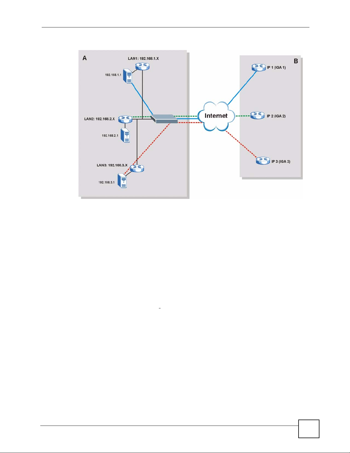
Chapter 7 Network Address Translation (NAT) Screens
Figure 51 NAT Application With IP Alias
7.1.5 NAT Mapping Types
NAT supports five types of IP/port mapping. They are:
• One to One: In One-to-One mode, the ZyXEL Device maps one local IP address to one
global IP address.
• Many to One: In Many-to-One mode, the ZyXEL Device maps multiple local IP
addresses to one global IP address. This is equivalent to SUA (for instance, PAT, port
address translation), ZyXEL’s Single User Account feature that previous ZyXEL routers
supported (the SUA Only option in today’s routers).
• Many to Many Overload: In Many-to-Many Overload mode, the ZyXEL Device maps
the multiple local IP addresses to shared global IP addresses.
• Many-to-Many No Overload:
maps each local IP address to a unique global IP address.
• Server: This type allows you to specify inside servers of different services behind the
NAT to be accessible to the outside world.
Port numbers do NOT change for One-to-One and Many-to-Many No Overload NAT
mapping types.
In Many-to-Many No Overload mode, the ZyXEL Device
P-660H-Tx v2 User’s Guide
99
Page 100

Chapter 7 Network Address Translation (NAT) Screens
The following table summarizes these types.
Table 27 NAT Mapping Types
TYPE IP MAPPING
One-to-One ILA1ÅÆ IGA1
Many-to-One (SUA/PAT) ILA1ÅÆ IGA1
ILA2ÅÆ IGA1
…
Many-to-Many Overload ILA1ÅÆ IGA1
ILA2ÅÆ IGA2
ILA3ÅÆ IGA1
ILA4ÅÆ IGA2
…
Many-to-Many No Overload ILA1ÅÆ IGA1
ILA2ÅÆ IGA2
ILA3ÅÆ IGA3
…
Server Server 1 IPÅÆ IGA1
Server 2 IPÅÆ IGA1
Server 3 IPÅÆ IGA1
7.2 SUA (Single User Account) Versus NAT
SUA (Single User Account) is a ZyNOS implementation of a subset of NAT that supports two
types of mapping, Many-to-One and Server. The ZyXEL Device also supports Full
Feature NAT to map multiple global IP addresses to multiple private LAN IP addresses of
clients or servers using mapping types as outlined in Table 27 on page 100.
• Choose SUA Only if you have just one public WAN IP address for your ZyXEL Device.
• Choose Full Feature if you have multiple public WAN IP addresses for your ZyXEL
Device.
7.3 SIP ALG
Some applications, such as SIP, cannot operate through NAT (are NAT un-friendly) because
they embed IP addresses and port numbers in their packets’ data payload.
Some NAT routers may include a SIP Application Layer Gateway (ALG). An Application
Layer Gateway (ALG) manages a specific protocol (such as SIP, H.323 or FTP) at the
application layer.
A SIP ALG allows SIP calls to pass through NAT by examining and translating IP addresses
embedded in the data stream.
When the ZyXEL Device registers with the SIP register server, the SIP ALG translates the
ZyXEL Device’s private IP address inside the SIP data stream to a public IP address. You do
not need to use STUN or an outbound proxy if your ZyXEL Device is behind a SIP ALG.
100
P-660H-Tx v2 User’s Guide
 Loading...