

Page 1

Prestige 201
ISDN Access Router
User's Guide
Version 2.50
(Feb. 2000)
Page 2

Page 3
Page 4

Prestige 201 ISDN Access Router
Prestige 201
ISDN Access Router
Copyright
Copyright © 2000 by ZyXEL Communications Corporation.
The contents of this publication may not be reproduced in any part or as a whole, transcribed, stored in a retrieval system,
translated into any language, or transmitted in any form or by any means, electronic, mechanical, magnetic, optical,
chemical, photocopying, manual, or otherwise, without the prior written permission of ZyXEL Communications
Corporation.
Published by ZyXEL Communications Corporation. All rights reserved.
Disclaimer
ZyXEL does not assume any liability arising out of the application or use of any products, or software described herein.
Neither does it convey any license under its patent rights nor the patent rights of others. ZyXEL further reserves the right
to make changes in any products described herein without notice. This publication is subject to change without notice.
Trademarks
ZyNOS (ZyXEL Network Operating System) is a registered trademark of ZyXEL Communications Inc. Other
trademarks mentioned in this publication are used for identification purposes only and may be properties of their
respective owners.
Copyrightii
Page 5

Prestige 201 ISDN Access Router
ZyXEL Limited Warranty
ZyXEL warrants to the original end user (purchaser) that this product is free from any defects in materials or
workmanship for a period of up to two (2) years from the date of purchase. During the warranty period, and upon proof
of purchase, should the product have indications of failure due to faulty workmanship and/or materials, ZyXEL will, at its
discretion, repair or replace the defective products or components without charge for either parts or labor, and to
whatever extent it shall deem necessary to restore the product or components to proper operating condition. Any
replacement will consist of a new or re-manufactured functionally equivalent product of equal value, and will be solely at
the discretion of ZyXEL. This warranty shall not apply if the product is modified, misused, tampered with, damaged by
an act of God, or subjected to abnormal working conditions.
Note
Repair or replacement, as provided under this warranty, is the exclusive remedy of the purchaser. This warranty is in lieu
of all other warranties, express or implied, including any implied warranty of merchantability or fitness for a particular
use or purpose. ZyXEL shall in no event be held liable for indirect or consequential damages of any kind of character to
the purchaser.
To obtain the services of this warranty, contact ZyXEL's Service Center; refer to the separate Warranty Card for your
Return Material Authorization number (RMA). Products must be returned Postage Prepaid. It is recommended that the
unit be insured when shipped. Any returned products without proof of purchase or those with an out-dated warranty will
be repaired or replaced (at the discretion of ZyXEL) and the customer will be billed for parts and labor. All repaired or
replaced products will be shipped by ZyXEL to the corresponding return address, Postage Paid (USA and territories
only). If the customer desires some other return destination beyond the U.S. borders, the customer shall bear the cost of
the return shipment. This warranty gives you specific legal rights, and you may also have other rights that vary from state
to state.
ZyXEL Limited Warranty iii
Page 6
Prestige 201 ISDN Access Router
Customer Support
If you have questions about your ZyXEL product or desire assistance, contact ZyXEL Communications Corporation
offices worldwide, in one of the ways listed. Our ftp sites are also available for software and ROM upgrades.
Method
Location
Worldwide
America
(Denmark)
E-MAIL – Support/ Sales Telephone/Fax Web Site/ FTP Site Regular Mail
support@zyxel.com.tw
support@europe.zyxel.com
+886-3-578-3942 www.zyxel.com
www.europe.zyxel.com
sales@zyxel.com.tw +886-3-578-2439 ftp.europe.zyxel.com
support@zyxel.com +1-714-632-0882
www.zyxel.comNorth
800-255-4101
sales@zyxel.com +1-714-632-0858 ftp.zyxel.com
support@zyxel.dk +45-3955-0700 www.zyxel.dkScandinavia
sales@zyxel.dk +45-3955-0707 ftp.zyxel.dk
support@zyxel.at +43-1-4948677-0 www.zyxel.atAustria
sales@zyxel.at +43-1-4948678 ftp.zyxel.co.at
support@zyxel.de 49-2405-6909-0 www.zyxel.deGermany
sales@zyxel.de 49-2405-6909-99
ZyXEL
Communications
Corp., 6 Innovation
Road II, ScienceBased Industrial Park,
HsinChu, Taiwan 300,
R.O.C.
ZyXEL
Communications Inc.,
1650 Miraloma
Avenue, Placentia,
CA 92870, U.S.A.
ZyXEL
Communications A/S,
Columbusvej 5, 2860
Soeborg, Denmark.
ZyXEL
Communications
Services GmbH.
Thaliastrasse
125a/2/2/4 A-1160
Vienna, Austria
ZyXEL
Deutschland GmbH.
Adenauerstr.
20/A4 D-52146
Wuerselen, Germany
iv Customer Support
Page 7

Prestige 201 ISDN Access Router
Table of Contents
Table of Contents ....................................................................................................................v
List of Figures....................................................................................................................... ix
List of Tables........................................................................................................................ xii
Preface.................................................................................................................................xiv
Prestige Scenarios...............................................................................................................xvi
Chapter 1.............................................................................................................................. 1-1
Getting to Know Your ISDN Router....................................................................................... 1-1
1.1 Features of the Prestige ...............................................................................................1-1
1.2 Internet Access with the Prestige 201 ........................................................................... 1-4
1.2.1 Internet Access........................................................................................................................................1-4
Chapter 2.............................................................................................................................. 2-1
Hardware Installation & Initial Setup.................................................................................... 2-1
2.1 Front Panel LEDS of P201........................................................................................... 2-1
2.2 Prestige 201 Rear Panel and Connections.................................................................... 2-2
2.3 Additional Installation Requirements............................................................................. 2-2
2.4 Housing...................................................................................................................... 2-3
2.5 Power On Your Prestige............................................................................................... 2-3
2.6 Navigating the SMT Interface .......................................................................................2-5
2.6.1 System Management Terminal Interface Summary..........................................................................2-6
2.7 Changing the System Password................................................................................... 2-7
2.8 Resetting the Prestige.................................................................................................. 2-7
2.8.1 Filename conventions.............................................................................................................................2-8
2.9 General Setup .............................................................................................................2-9
2.10 ISDN Setup Menus................................................................................................ 2-10
2.10.1 ISDN Setup Menu............................................................................................................................2-10
2.10.2 ISDN Advanced Setup....................................................................................................................2-11
2.10.3 NetCAPI Setup.................................................................................................................................2-13
2.10.4 RVS-COM.........................................................................................................................................2-14
2.11 Ethernet Setup ...................................................................................................... 2-17
Table of Contents v
Page 8

Prestige 201 ISDN Access Router
2.11.1 General Ethernet Setup ....................................................................................................................2-17
Chapter 3.............................................................................................................................. 3-1
Internet Access..................................................................................................................... 3-1
3.1 Factory Ethernet Defaults ............................................................................................ 3-1
3.2 TCP/IP Parameters ..................................................................................................... 3-1
3.2.1 IP Address and Subnet Mask.................................................................................................................3-1
3.2.2 RIP Setup..................................................................................................................................................3-2
3.2.3 DHCP Configuration ...............................................................................................................................3-2
3.3 TCP/IP Ethernet Setup and DHCP ................................................................................3-4
3.4 Internet Access Configuration....................................................................................... 3-7
3.4.1 Example Internet Access Configuration..............................................................................................3-8
3.5 Single User Account .................................................................................................. 3-10
3.5.1 Advantages of SUA...............................................................................................................................3-11
3.5.2 Single Us er Account Configuration....................................................................................................3-11
3.6 Multiple Servers behind SUA ......................................................................................3-12
3.6.1 Configuring a Server behind SUA......................................................................................................3-12
Chapter 4.............................................................................................................................. 4-1
Remote Node Configuration................................................................................................. 4-1
4.1 Remote Node Setup ....................................................................................................4-1
4.1.1 Remote Node Profile ...............................................................................................................................4-1
4.1.2 Outgoing Authentication Protocol........................................................................................................4-4
4.1.3 Remote Node Filter..................................................................................................................................4-5
Chapter 5.............................................................................................................................. 5-1
Static Route Setup............................................................................................................... 5-1
Chapter 6.............................................................................................................................. 6-1
Filter Configuration .............................................................................................................. 6-1
6.1 About Filtering .............................................................................................................6-1
6.2 Configuring a Filter Set ................................................................................................ 6-4
6.2.1 Filter Rules Summary Menus................................................................................................................6-5
6.3 Configuring a Filter Rule.............................................................................................. 6-7
vi Table of Contents
Page 9

Prestige 201 ISDN Access Router
6.3.1 Filter Types and SUA.............................................................................................................................6-7
6.3.2 TCP/IP Filter Rule ...................................................................................................................................6-8
6.3.3 Generic Filter Rule................................................................................................................................6-12
6.4 Applying Filters and Factory Defaults.......................................................................... 6-14
6.4.1 Ethernet Traffic......................................................................................................................................6-14
6.4.2 Remote Node Filters.............................................................................................................................6-14
Chapter 7.............................................................................................................................. 7-1
Telnet Configuration and Capabilities ..................................................................................7-1
7.1 Telnet Configuration..................................................................................................... 7-1
7.2 Telnet Under SUA ........................................................................................................7-1
7.3 Telnet Capabilities ....................................................................................................... 7-2
Chapter 8.............................................................................................................................. 8-1
System Maintenance............................................................................................................ 8-1
8.1 System Status ............................................................................................................ 8-2
System Information...............................................................................................................................................8-5
8.1.2 Console Port Speed.................................................................................................................................8-6
8.2 Log and Trace............................................................................................................. 8-7
8.2.1 Viewing Error Log .................................................................................................................................. 8-7
8.2.2 Syslog And Accounting.........................................................................................................................8-8
8.2.3 Call-Triggering Packet...........................................................................................................................8-8
8.3 Diagnostic................................................................................................................. 8-10
8.4 Boot module commands ............................................................................................ 8-13
8.5 Command Interpreter Mode....................................................................................... 8-13
8.6 Call Control ...............................................................................................................8-14
8.6.1 Call Control Parameters ......................................................................................................................8-15
8.6.2 Blacklist..................................................................................................................................................8-16
8.6.3 Budget Management.............................................................................................................................8-17
8.6.4 Call History............................................................................................................................................8-17
8.7 Time and Date Setting ............................................................................................... 8-18
Chapter 9.............................................................................................................................. 9-1
Table of Contents vii
Page 10

Prestige 201 ISDN Access Router
Schedule Setup.................................................................................................................... 9-1
Chapter 10.......................................................................................................................... 10-1
Backup, Restore and Upload.............................................................................................. 10-1
10.1 Backup Configuration............................................................................................. 10-1
10.1.1 Backup using the Console Port.......................................................................................................10-1
10.1.2 Back up using FTP............................................................................................................................10-2
10.1.3 Back up using TFTP.........................................................................................................................10-2
10.2 Restore Configuration ............................................................................................10-4
10.2.1 Restore using the Console Port.......................................................................................................10-4
10.2.2 Restore using FTP.............................................................................................................................10-6
10.2.3 Restore using TFTP..........................................................................................................................10-6
10.3 Firmware Update ...................................................................................................10-7
10.3.1 Upload through the Console Port...................................................................................................10-7
10.3.2 Upload using FTP.............................................................................................................................10-9
10.3.3 Upload using TFTP........................................................................................................................10-11
Chapter 11 ..........................................................................................................................11-1
Troubleshooting .................................................................................................................11-1
11.1 Problems Starting Up the Prestige ..........................................................................11-1
11.2 Problems With the ISDN Line .................................................................................11-2
11.3 Problems with the LAN Interface.............................................................................11-3
11.4 Problems Connecting to a Remote Node or ISP.......................................................11-3
Acronyms and Abbreviations.................................................................................................A
Index......................................................................................................................................C
viii Table of Contents
Page 11

Prestige 201 ISDN Access Router
List of Figures
Figure 1-1 Internet Access Application.......................................................................................................................1-4
Figure 2-1 Front Panel of P201.....................................................................................................................................2-1
Figure 2-2 Prestige 201 Rear Panel..............................................................................................................................2-2
Figure 2-3 Power-On Display for DSS1 switch.........................................................................................................2-3
Figure 2-4 Login Screen ................................................................................................................................................. 2-4
Figure 2-5 SMT Main Menu..........................................................................................................................................2-6
Figure 2-6 Menu 23 - System Password......................................................................................................................2-7
Figure 2-7 Booting Up the Prestige..............................................................................................................................2-8
Figure 2-8 Menu 1 – General Setup.............................................................................................................................2-9
Figure 2-9 Menu 2 – ISDN Setup...............................................................................................................................2-10
Figure 2-10 Menu 2.1 - ISDN Advanced Setup.......................................................................................................2-11
Figure 2-11 Prestige behind a PABX ..........................................................................................................................2-12
Figure 2-12 Loopback test...........................................................................................................................................2-13
Figure 2-13 Configuration Example...........................................................................................................................2-15
Figure 2-14 Menu 2.2 - NetCAPI Setup....................................................................................................................2-16
Figure 2-15 Menu 3 - Ethernet Setup.........................................................................................................................2-17
Figure 2-16 Menu 3.1 - General Ethernet Setup......................................................................................................2-18
Figure 3-1 Menu 3.2 – TCP/IP and DHCP Ethernet Setup......................................................................................3-4
Figure 3-2 Menu 4 – Internet Access Setup...............................................................................................................3-8
Figure 3-3 Single User Account Topology ...............................................................................................................3-10
Figure 3-4 Menu 4 – Internet Access Setup for Single User Account ................................................................. 3-11
Figure 3-5 SUA Server Setup......................................................................................................................................3-13
Figure 4-1 Menu 11 - Remote Node Profile ................................................................................................................ 4-2
Figure 4-2 Menu 11.1 – Remote Node Filter..............................................................................................................4-5
Figure 5-1 Example of Static Routing Topology ....................................................................................................... 5-1
Figure 5-2 Menu 12 - IP Static Route Setup...............................................................................................................5-2
Figure 5-3 Edit IP Static Route.....................................................................................................................................5-2
Figure 6-1 Outgoing Pack et Filtering Process............................................................................................................6-2
Figure 6-2 Filter Rule Process.......................................................................................................................................6-3
Figure 6-3 Menu 21 - Filter Set Configuration...........................................................................................................6-4
Figure 6-4 Menu 21.1 - Filter Rules Summary...........................................................................................................6-5
List of Figures/Tables ix
Page 12

Prestige 201 ISDN Access Router
Figure 6-5 Menu 21.2 - Filter Rules Summary ...........................................................................................................6-5
Figure 6-6 Protocol and Device Filter Sets..................................................................................................................6-8
Figure 6-7 Menu 21.1.1 - TCP/IP Filter Rule..............................................................................................................6-9
Figure 6-8 Executing an IP Filter.................................................................................................................................6-11
Figure 6-9 Menu 21.1.2 - Generic Filter Rule...........................................................................................................6-12
Figure 6-10 Filtering Ethernet traffic..........................................................................................................................6-14
Figure 6-11 Filtering Remote Node traffic................................................................................................................6-15
Figure 7-1 Telnet Configuration on a TCP/IP Network.............................................................................................7-1
Figure 8-1 Menu 24 - System Maintenance................................................................................................................8-1
Figure 8-2 Menu 24.1 - System Maintenance – Status..............................................................................................8-2
Figure 8-3 LAN Packet That Triggered Last Call.......................................................................................................8-4
Figure 8-4 System Maintenance - Information...........................................................................................................8-5
Figure 8-5 Menu 24.2.2 – System Maintenance – Change Console Port Speed.................................................8-6
Figure 8-6 Examples of Error and Information Messages ........................................................................................8-7
Figure 8-7 Menu 24.3.2 - System Maintenance - Syslog and Accounting............................................................8-8
Figure 8-8 Call-Triggering Packet Example................................................................................................................8-9
Figure 8-9 Menu 24.4 - System Maintenance - Diagnostic....................................................................................8-10
Figure 8-10 Display for a Successful Manual Call...................................................................................................8-11
Figure 8-11 Display for a Failed Authentication......................................................................................................8-12
Figure 8-12 Boot module commands..........................................................................................................................8-13
Figure 8-13 Command mode........................................................................................................................................8-13
Figure 8-14 Menu 24.9 - System Maintenance - Call Control...............................................................................8-14
Figure 8-15 Call Control Parameters ..........................................................................................................................8-15
Figure 8-16 Menu 24.9.2 - Blacklist...........................................................................................................................8-16
Figure 8-17 Menu 24.9.3 - Budget Management......................................................................................................8-17
Figure 8-18 Call History ...............................................................................................................................................8-18
Figure 8-19 System Maintenance – Time and Date Setting....................................................................................8-19
Figure 9-1 Schedule Setup..............................................................................................................................................9-1
Figure 9-2 Schedule Set Setup.......................................................................................................................................9-2
Figure 10-1 Menu 24.5 –Backup Configuration using the Console Port .............................................................10-1
Figure 10-2 Receive File...............................................................................................................................................10-2
Figure 10-3 Successful Backup....................................................................................................................................10-2
Figure 10-4 TFTP Example ..........................................................................................................................................10-4
x List of Figures/Tables
Page 13

Prestige 201 ISDN Access Router
Figure 10-5 Menu 24.6 –Restore Configuration using the Console Port.............................................................10-5
Figure 10-6 Send File....................................................................................................................................................10-5
Figure 10-7 Successful Restoration............................................................................................................................10-5
Figure 10-8 Menu 24.7 - System Maintenance - Upload Firmware .....................................................................10-7
Figure 10-9 Menu 24.7.1 - Uploading Router Firmware........................................................................................10-8
Figure 10-10 Menu 24.7.2 - System Maintenance - Upload Router Configuration File...................................10-9
Figure 10-11 FTP Example ........................................................................................................................................10-10
Figure 10-12 Edit Host ...............................................................................................................................................10-10
Figure 10-13 Username Prompt................................................................................................................................10-11
Figure 10-14 Files Tra nsfer........................................................................................................................................10-11
List of Figures/Tables xi
Page 14

Prestige 201 ISDN Access Router
List of Tables
Table 1-1 Prestige Scenarios..........................................................................................................................................xvi
Table 2-1 LED functions.................................................................................................................................................2-1
Table 2-2 Main Menu Commands.................................................................................................................................2-5
Table 2-3 Main Menu Summary....................................................................................................................................2-6
Table 2-4 General Setup Menu Fields..........................................................................................................................2-9
Table 2-5 ISDN Advanced Setup Fields....................................................................................................................2-11
Table 2-6 NetCAPI Setup Fields.................................................................................................................................2-16
Table 3-1 DHCP Ethernet Setup Menu Fields............................................................................................................3-5
Table 3-2 TCP/IP Ethernet Setup Menu Fields ...........................................................................................................3-6
Table 3-3 Internet Account Information.......................................................................................................................3-7
Table 3-4 Internet Access Setup Menu Fields.............................................................................................................3-9
Table 3-5 Single User Account Menu Fields.............................................................................................................3-12
Table 3-6 Services vs. Port number.............................................................................................................................3-13
Table 4-1 Remote Node Profile Menu Field s ..............................................................................................................4-3
Table 5-1 Edit IP Static Route Menu Fields................................................................................................................5-2
Table 6-1 Abbreviations Used in the Filter Rules Summary Menu.........................................................................6-6
Table 6-2 Abbreviations Used If Filter Type Is IP......................................................................................................6-7
Table 6-3 Abbreviations Used If Filter Type Is GEN................................................................................................6-7
Table 6-4 TCP/IP Filter Rule Menu Fields ..................................................................................................................6-9
Table 6-5 Generic Filter Rule Menu Fields...............................................................................................................6-13
Table 8-1 System Maintenance - Status Menu Fields................................................................................................8-3
Table 8-2 Fields in System Maintenance.....................................................................................................................8-6
Table 8-3 System Maintenance Menu Syslog Parameters.........................................................................................8-8
Table 8-4 System Maintenance Menu Diagnostic....................................................................................................8-10
Table 8-5 Call Control Parameters Fields..................................................................................................................8-15
Table 8-6 Call History Fields.......................................................................................................................................8-18
Table 8-7 Time and Date Setting Fields.....................................................................................................................8-19
Table 9-1 Schedule Set Setup Fields.............................................................................................................................9-2
Table 11 -1 Troubleshooting the Start-Up of your Prestige.....................................................................................11-1
Table 11 -2 Troubleshooting the ISDN Line...............................................................................................................11-2
Table 11 -3 Troubleshooting the LAN Interface........................................................................................................11-3
xii List of Figures/Tables
Page 15

Prestige 201 ISDN Access Router
Table 11 -4 Troubleshooting a Connection to a Remote Node or ISP...................................................................11-3
List of Figures/Tables xiii
Page 16

Prestige 201 ISDN Access Router
Preface
About Your Prestige
Congratulations on your purchase of the Prestige 201 ISDN Router. Don’t forget to register your Prestige
(fast, easy online registration at www.zyxel.com) for free future product updates and information.
The Prestige 201 is a high-performance router that offers a complete Internet Access solution and is
extremely easy to configure.
The user-friendly Prestige Network Commander (PNC) is a C++ utility that allows you to manage the
Prestige via Windows. You can also manage the Prestige via the SMT (System Management Terminal), a
menu-driven interface that you can access from either a terminal emulator or telnet.
Please visit our web site at www.zyxel.com for the latest release notes and other information about this
product.
Setup Information
ISDN Line
1. Contact your local telephone company’s ISDN Ordering Center to find out what type of ISDN
service is available and the switch type.
2. When the telephone company installs your ISDN line, please be sure to obtain and write down the
following information for future use:
• ISDN switch type
• ISDN telephone number(s)
• ISDN Service Profile Identifier s (SPID) number(s) (only for North America).
• ISDN Data Link Connection Mode
Supplemental services such as Call Forwarding are supported by the Prestige but must be subscribed to
separately from the telephone company.
Ethernet Setup Information
IP Address - The IP Address is the unique 32-bit number assigned to your Prestige. This address is written
in dotted decimal notation (four 8-bit numbers, between 0 and 255, separated by periods), e.g., 192.168.1.1.
Please note that every machine on an internet must have a unique IP address - do not assign an arbitrary
address to any machine. If you are not sure as to which IP address to assign to the Prestige, contact your
Internet Service Provider (ISP) or refer to Chapter 3 of this guide for more details.
xiv Preface
Page 17

Prestige 201 ISDN Access Router
IP Subnet Mask - An IP address consists of two parts, the network ID and the host ID. The IP Subnet Mask
is used to specify the network ID portion of the address, expressed in dotted decimal notation. The Prestige
automatically calculates this mask based on the IP address that you assign. Unless you have a special need
for subnetting, use the default mask as calculated by the Prestige.
Syntax Conventions
• “Enter” means for you to type one or more characters and press the carriage return. “Select” or
“Choose” means for you to select one from the predefined choices.
• The SMT menu titles and labels are in Bold Times font. The choices of a menu item are in Bold Arial
font. A single keystroke is in Arial font and enclosed in square brackets, for instance, [ENTER] means
the Enter, or carriage return, key; [ESC] means the Escape key.
• For brevity’s sake, we will use “e.g.” as a shorthand for “for instance”, and “i.e.” as a shorthand for “that
is” or “in other words” throughout this manual.
• The Prestige 201 may also be referred to as the Prestige or the P201 from now on, in this manual.
Preface xv
Page 18

Prestige 201 ISDN Access Router
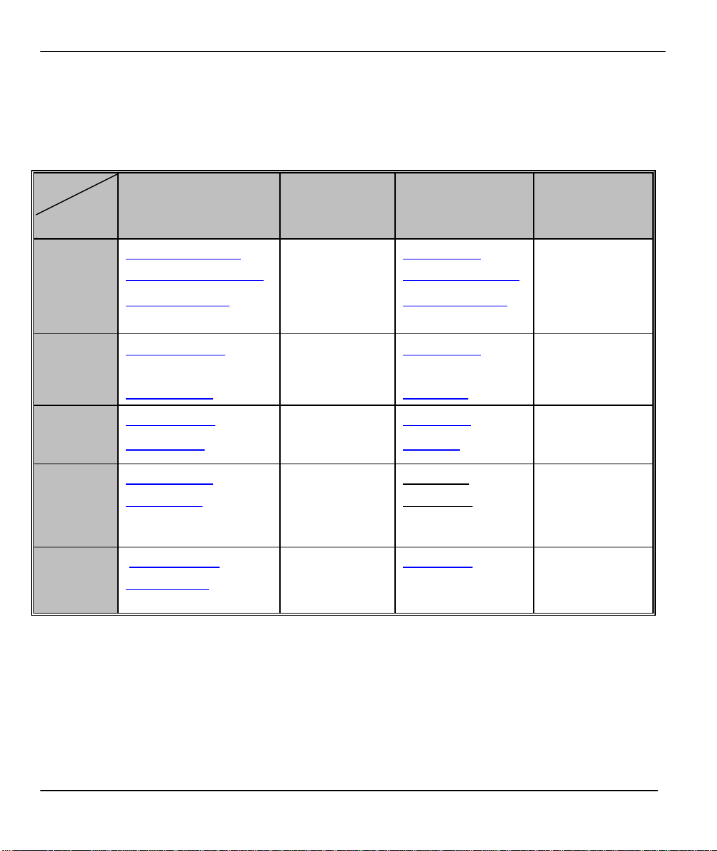
Prestige Scenarios
For fast access to example SMT menus to show you how to
configure the Prestige for various scenarios go to the
following sections.
SCENARIO GO TO SECTION
To reset your Prestige 2.8
DHCP 3.3
Internet Access 3.4.1
To configure SUA 3.5.2
To apply filters 6.4
To setup NetCAPI 2.10.3
To setup schedules Chapter 9
Table 1-1 Prestige Scenarios
xvi SMT Scenarios
Page 19
Prestige 201 ISDN Access Router
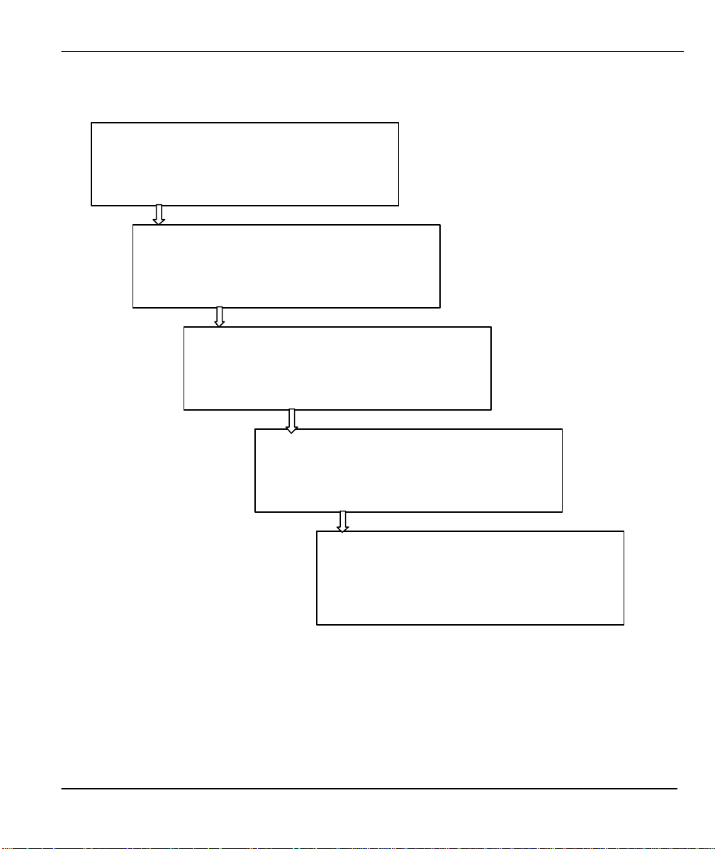
General Structure of this Manual
Getting Started (Chapters 1-2)
This helps you connect, install and setup your Prestige
to operate on your network.
The Internet (Chapter 3)
This shows you how to configure your Prestige for
Internet access.
Advanced Applications (Chapters 4-5)
This shows how to configure remote node and set up
static routes.
Management & Maintenance (Chapters 6-10)
This shows you how to create/apply filters, use Telnet
and manage/maintain your system.
Troubleshooting (Chapter 11)
This provides information about solving common
problems.
Structure Of The Manual xvii
Page 20

Page 21

Prestige 201 ISDN Access Router
Chapter 1
Getting to Know Your ISDN Router
This chapter covers the key features and main
applications of your Prestige.
The Prestige 201 ISDN router is a high quality and value-for-money product that is specially designed for
home users to access Internet. The built-in 10BaseT four-port hub provides users easy and immediate LAN
infrastructure solution without purchasing another hub.
1.1 Features of the Prestige
Four-Port 10M Ethernet Hub Interface
The P201 provides four-port 10M hub for Ethernet LAN connection.
ISDN Basic Rate Interface (BRI) Support
The Prestige supports a single BRI. A BRI offers two 64 Kbps channels, which can be used independently
for two destinations or be bundled to speed up data transfer.
Single User Account (SUA)
The SUA™ (Single User Account) feature allows multiple users to share a single IP address (either dynamic
or static) assigned by your Internet Service Provider (ISP).
TCP/IP and PPP Support
♦ TCP/IP (Transmission Control Protocol/Internet Protocol) network layer protocol.
♦ PPP/MP (Point-to-Point Protocol/Multilink Protocol) link layer protocol.
Dial-On-Demand
The Dial-On-Demand feature allows the Prestige to automatically place a call to a remote gateway based on
the triggering packet’s destination without user intervention.
PPP Multilink
The Prestige can bundle multiple links in a single connection using PPP Multilink Protocol (MP ). The
number of links can be either statically configured or dynamically managed based on traffic demand.
Getting To Know Your Router 1-1
Page 22

Prestige 201 ISDN Access Router
Bandwidth-On-Demand
The Prestige dynamically allocates bandwidth by dialing and dropping connections according to traffic
demand.
NetCAPI Support
Your ZyXEL routers can now take full advantage of popular European ISDN services. NetCAPI is ZyXEL's
implementation of CAPI (Common ISDN Application Program Interface) capabilities over a network. It runs
over DCP (Device Control Protocol) developed by RVS-COM.
NetCAPI can be used for applications such as Eurofile transfer, file transfer, G3/G4 Fax, Autoanswer host
mode, telephony, etc. on Windows 95/98/NT platforms.
ISDN PtP Support
Your Prestige now supports ISDN Point-to-Point (PtP) in addition to Point -to- Multi Point (PtMP)
connections.
Call Scheduling
The Call Scheduling feature allows you to manage the remote node based on your pre-configured schedule.
You can dictate when a remote node should be called and for how long.
Full Network Management
♦ Accessing SMT (System Management Terminal) through telnet connection.
♦ Windows-based PNC (Prestige Network Commander).
Logging and Tracing
♦ CDR (Call Detail Record) to help to analyze and manage outgoing calls.
♦ Built-in message logging and packet tracing.
♦ Unix syslog facility support.
PAP and CHAP Security
The Prestige supports PAP (Password Authentication Protocol) and CHAP (Challenge Handshake
Authentication Protocol). CHAP is more secure than PAP; however, PAP is readily available on more
platforms.
DHCP Support
DHCP (Dynamic Host Configuration Protocol) allows the workstations on your LAN to obtain the
configuration from the Prestige.
1-2 Getting To Know Your Router
Page 23

Prestige 201 ISDN Access Router
Data Compression
Your Prestige incorporates Stac data compression to speed up data transfer. Stac is the de facto standard of
data compression over PPP links.
Networking Compatibility
Your Prestige is compatible with remote access products from other manufacturers such as Ascend, Cisco,
and 3Com. Furthermore, it supports Microsoft Windows 95 and Windows NT remote access capability.
Prestige Network Commander (PNC)
The PNC is a C++ based utility designed to allow users to access the Prestige’s management settings via
Windows.
Upgrade Firmware via LAN
In addition to the direct console port connection, the Prestige supports the up/downloading of firmware and
the configuration file using TFTP (Trivial File Transfer Protocol) and FTP (File Transfer Protocol) over LAN
and WAN. Upload using TFTP over the WAN is not recommended because of potential data corruption
problems.
Getting To Know Your Router 1-3
Page 24
Prestige 201 ISDN Access Router
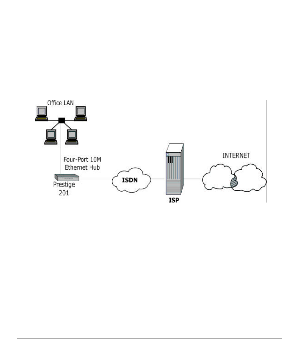
1.2 Internet Access with the Prestige 201
1.2.1 Internet Access
The Prestige is the ideal high-speed Internet access solution. Your Prestige supports the TCP/IP protocol,
which the Internet uses exclusively. It is also compatible with access servers manufactured by major vendors
such as Cisco and Ascend. A typical Internet Access application is shown next.
Figure 1-1 Internet Access Application
Internet Single User Account
For a SOHO (Small Office/Home Office) environment, your Prestige offers the Single User Account (SUA)
feature that allows multiple users on the LAN (Local Area Network) to access the Internet concurrently for
the cost of a single user. Single User Account address mapping can also be used for other LAN to LAN
connections.
1-4 Getting To Know Your Router
Page 25
Prestige 201 ISDN Access Router
Chapter 2
Hardware Installation & Initial Setup
This chapter shows you how to make the cable connections to your
Prestige as well as set up your ISDN connection using the SMT.
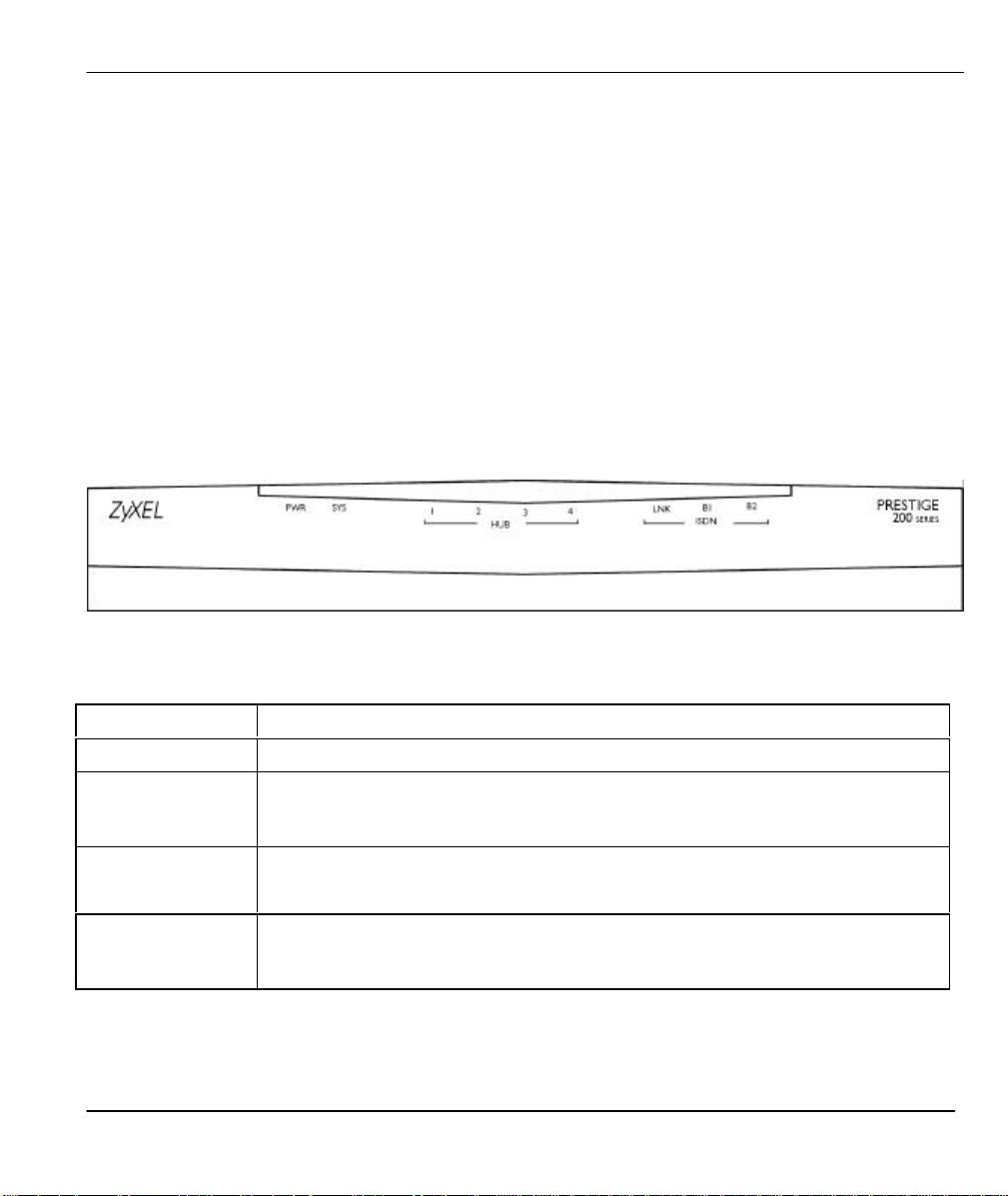
2.1 Front Panel LEDS of P201
The LED indicators on the front panel indicate the operational status of the Prestige 201. The table below the
diagram describes the LED functions:
Figure 2-1 Front Panel of P201
Table 2-1 LED functions
LED
PWR
SYS A steady on SYS (system) LED indicates the Prestige is on and functioning properly
HUB
1, 2, 3, 4
ISDN
LNK, B1, B2
Hardware Installation & Initial Setup 2-1
The PWR (power) LED is on when power is applied to the Prestige.
while an off SYS LED indicates the system is not ready or a malfunction. The
system is rebooting when the SYS LED is blinking.
A steady green light indicates a successful 10Mb Ethernet connection. The LED will
blink when data is being sent/received.
The LNK LED is on when the Prestige is connected to an ISDN switch and the line
has been successfully initialized. The B1 (B2) LED remains steady on when data is
being sent/received on the B1 (B2) bearer channel.
Description
Page 26
Prestige 201 ISDN Access Router
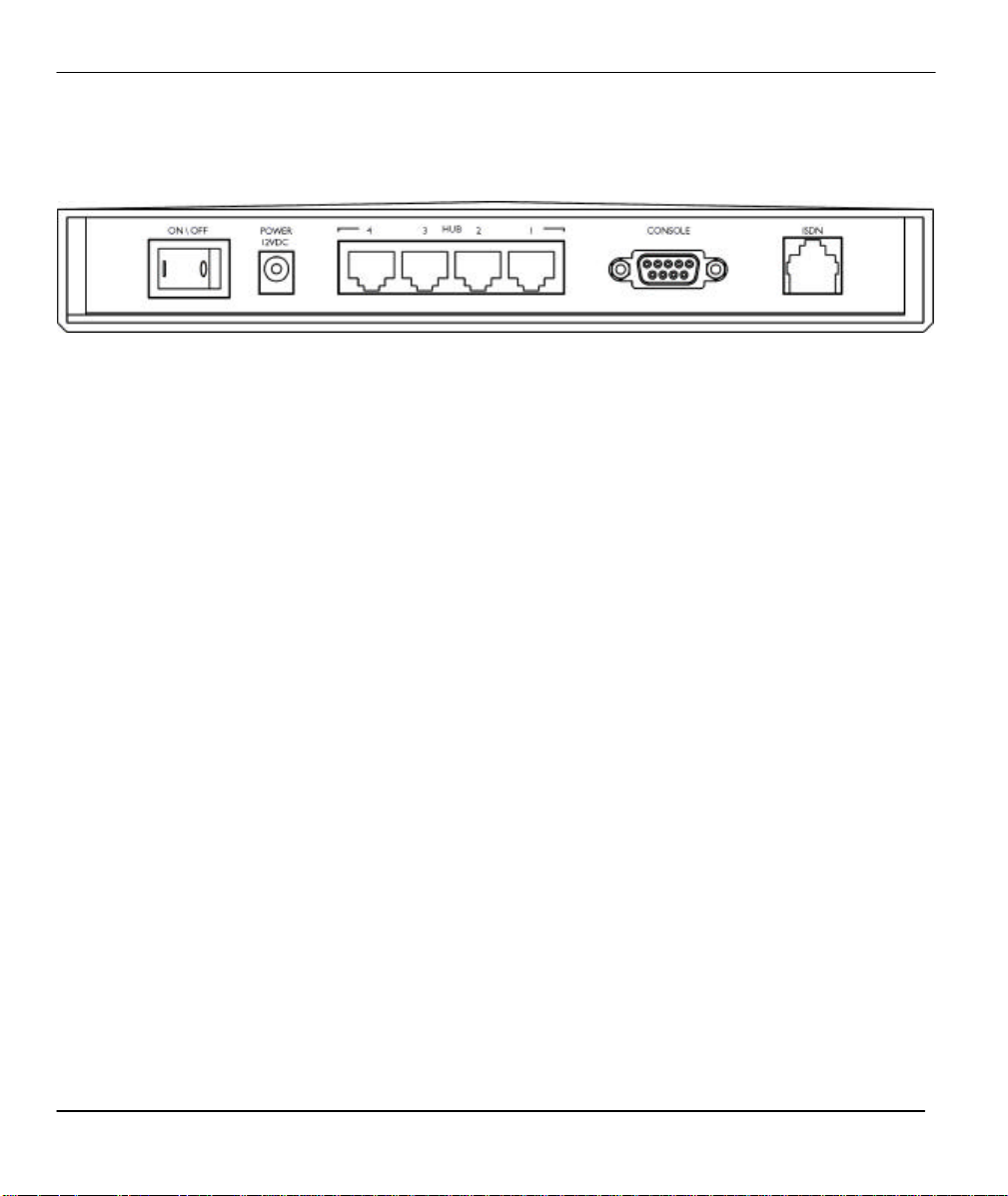
2.2 Prestige 201 Rear Panel and Connections
The next figure shows the rear panel of your Prestige 201.
Figure 2-2 Prestige 201 Rear Panel
This section outlines how to connect your Prestige 201 to the LAN and to the ISDN network.
Step 1. Connecting the ISDN Line
Connect the Prestige to the ISDN network using the included ISDN cable. Plug one end of the cable into the
port labeled ISDN and the other to the ISDN wall jack.
Step 2. Connecting a Workstation to the Prestige
Ethernet 10Base-T networks use Unshielded Twisted Pair (UTP) cable with RJ-45 connectors that look like a
bigger telephone plug with 8 pins. Use the crossover cable to connect your Prestige 201 to a computer
directly or use straight through Ethernet cable (white tag) to connect to an external hub.
Step 3. Connecting the Power Adapter to your Prestige
Connect the power adapter to the port labeled POWER on the rear panel of your Prestige.
Step 4. Connecting the Console Port
For the initial configuration of your Prestige, you need to use terminal emulator software on a workstation
and connect it to the Prestige through the console port. Connect the 9-pin (smaller) end of the console cable
to the console port of the Prestige and the 25-pin (bigger) end to a serial port (COM1, COM2 or other COM
port) of your workstation. You can use an extension RS-232 cable if the enclosed one is too short.
After the initial setup, you can modify the configuration remotely through telnet connections. See the Telnet
Configuration and Capabilities chapter for detailed instructions on using telnet to configure your Prestige.
2.3 Additional Installation Requirements
In addition to the contents of your package, there are other hardware and software requirements you need
before you can install and use your Prestige. These requirements include:
1. A computer with Ethernet 10Base-T NIC (Network Interface Card).
2. A computer equipped with communications software configured to the following parameters:
2-2 Hardware Installation & Initial Setup
Page 27

Prestige 201 ISDN Access Router
Copyright (c) 1994 - 2000 ZyXEL Communications Corp.
♦ VT100 terminal emulation.
♦ 9600 Baud.
♦ No parity, 8 Data bits, 1 Stop bit.
♦ Flow Control set to None.
After the Prestige is properly set up, you can make future changes to the configuration through telnet
connections.
2.4 Housing
Your Prestige's housing has ventilation slots for cooling and clip-out legs that fit snugly into grooves for
sturdy stacking with better airflow. ZyXEL recommends that you do not stack more than 4 routers for
maximum stack stability and cooling.
2.5 Power On Your Prestige
At this point, you should have connected the console port, the ISDN BRI port, the Ethernet port and the
power port to the appropriate devices or lines. You can now apply power to the Prestige by flipping the
power switch to on (I is ON, O is OFF).
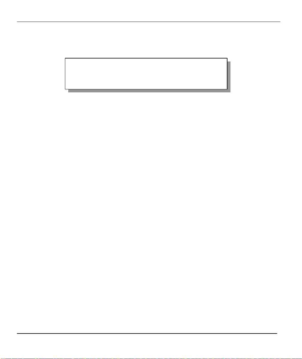
Step 1. Initial Screen
When you power on your Prestige, it performs several internal tests as well as line initialization. After the
initialization, the Prestige asks you to press [ENTER] to continue, as shown.
initialize ch =0, ethernet address: 00:a0:c5:ff:aa:01
(2) DSS1:
Press ENTER to continue...
Figure 2-3 Power-On Display for DSS1 switch
Step 2. Entering Password
The login screen appears after you press Enter, prompting you to enter the password, as shown below.
For your first login, enter the default password 1234. As you type the password, the screen displays a (X)
for each character you type.
Hardware Installation & Initial Setup 2-3
Page 28
Prestige 201 ISDN Access Router
Please note that if there is no activity for longer than 5 minutes after you log in, your Prestige will
automatically log you out and will display a blank screen. If you see a blank screen, press [ENTER] to bring
up the login screen again.
Enter Password : XXXX
Figure 2-4 Login Screen
2-4 Hardware Installation & Initial Setup
Page 29

Prestige 201 ISDN Access Router
2.6 Navigating the SMT Interface
The SMT (System Management Terminal) is the interface that you use to configure your Prestige.
Several operations that you should be familiar with before you attempt to modify the configuration are listed
in the table below.
Table 2-2 Main Menu Commands
Operation Press/<read> Description
Move forward to
another menu
Move backward to
a previous menu
Move to a
submenu
Move the cursor [ENTER] or
Enter information Fill in, or
Required fields
N/A fields <N/A> Some of the fields in the SMT will show a <N/A>. This symbol
Save your
configuration
[ENTER] To move forward to another menu, type in the number of the
desired menu and press [ENTER].
[ESC] Press the [ESC] key to move back to the previous menu.
Press the
[Space bar] to
change No to
Yes then press
[ENTER].
[Up]/[Down]
arrow keys
Press the
[Space bar] to
toggle
<?>
[ENTER] Save your configuration by pressing [ENTER] at the message
Fields beginning with “Edit” have a default setting of No. Press the
[Space bar] to change No to Yes, then press [ENTER] to go to a
submenu.
Within a menu, press [ENTER] to move to the next field. You can
also use the [Up]/[Down] arrow keys to move to the previous and
the next field, respectively.
You need to fill in two types of fields. The first requires you to type
in the appropriate information. The second allows you to cycle
through the available choices by pressing the [Space] bar.
All fields with the symbol <?> must be filled in order be able to save
the new configuration.
refers to an option that is Not Applicable.
[Press ENTER to confirm or ESC to cancel]. Saving the data on the
screen will take you, in most cases to the previous menu.
Exit the SMT Type 99, then
press [ENTER].
Type 99 at the Main Menu prompt and press [ENTER] to exit the
SMT interface.
Hardware Installation & Initial Setup 2-5
Page 30
Prestige 201 ISDN Access Router
Copyright (c) 1994 - 2000 ZyXEL Communications Corp.
After you enter the password, the SMT displays the Main Menu, as shown.
Prestige 201 Main Menu
Getting Started
1. General Setup
2. ISDN Setup
3. Ethernet Setup
4. Internet Access Setup
Advanced Applications
11. Remote Node Setup
12. Static Routing Setup
15. SUA Server Setup
Enter Menu Selection Number:
Advanced Management
21. Filter Set Configuration
23. System Security
24. System Maintenance
26. Schedule Setup
99. Exit
Figure 2-5 SMT Main Menu
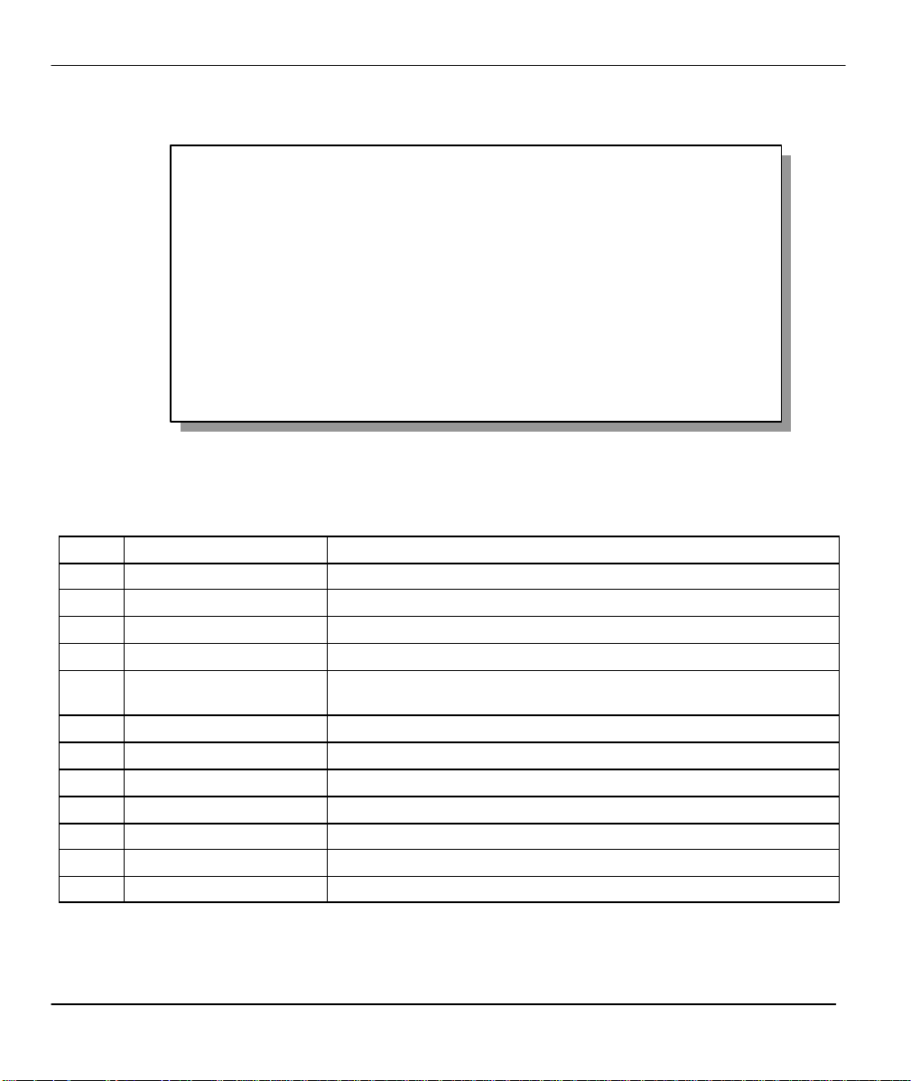
2.6.1 System Management Terminal Interface Summary
Table 2-3 Main Menu Summary
# Menu Title Description
1 General Setup Use this menu to setup general information.
2 ISDN Setup Use this menu to setup the ISDN.
3 Ethernet Setup Use this menu to setup Ethernet.
4 Internet Access Setup A quick and easy way to setup Internet connection.
11 Remote Node Setup Use this menu to setup the Remote Node for LAN-to-LAN connection,
including Internet connection.
12 Static Routing Setup Use this menu to setup static route for different protocols.
15 SUA Server Setup Use this menu to specify inside servers when SUA is enabled.
21 Filter Set Configuration Use this menu to setup filters to provide security, call control, etc.
23 System Security Use this menu to setup security related parameters.
24 System Maintenance This menu provides system status, diagnostics, software upload, etc.
26 Schedule Setup Use this menu to schedule dial-out calls.
99 Exit To exit from SMT and return to the blank screen.
2-6 Hardware Installation & Initial Setup
Page 31

Prestige 201 ISDN Access Router
Menu 23 – System Password
2.7 Changing the System Password
The first thing your should do before anything else is to change the default system password by following the
steps below .
Step 1. Enter 23 in the Main Menu to open Menu 23 - System Password as shown below.
When this menu appears, type in your existing system password, i.e., 1234, and press [ENTER].
Old Password= ****
New Password= ****
Retype to confirm= ****
Enter here to CONFIRM or ESC to CANCEL:
Figure 2-6 Menu 23 - System Password
Step 2. Enter your new system password (up to 30 characters), and press [ENTER].
Step 3. Re-type your new system password for confirmation and press [ENTER].
Note that as you type a password, the screen displays a (*) for each character you type.
2.8 Resetting the Prestige
If you have forgotten your password or for some reason cannot access the SMT menu you will need to
reinstall the configuration file. Uploading the configuration file replaces the current configuration file with
the default configuration file, you will lose all configurations that you had before and the speed of the
console port will be reset to the default of 9600 bps with 8 data bit, no parity and 1 stop bit (8n1). The
password will be reset to the default of 1234, also.
Turn off the Prestige and begin a Telnet session or use a teminal emulator program such as HyperTerminal
with the default console port settings. Turn on the Prestige again. You should see the following screen. When
you see the message "Press Any key to enter Debug Mode within 3 seconds", press any key to enter debug
mode. You should already have downloaded the "romfile.zip" file from the Internet and unzipped it.
Hardware Installation & Initial Setup 2-7
Page 32

Prestige 201 ISDN Access Router
Bootbase Version: V1.03 | 3/18/1999 15:04:51
RAM: Size = 4096 Kbytes
FLASH: intel 8M
ZyNOS Version: V2.30a00 | 5/5/1999 9:37:32
Press any key to enter debug mode within 3 seconds.
........................................
Enter Debug Mode
atlc
Now erase flash ROM for upload ……
Programming successful…
OK
Figure 2-7 Booting Up the Prestige
Follow the procedure below to upload the configuration file:
1. Enter “atlc” after the “Enter Debug Mode” message.
2. Wait for the “Starting XMODEM upload” message before activating Xmodem upload on your
terminal.
3. After successful firmware upload, enter “atgo” to restart the Prestige.
The Prestige is now reinitialized with default configuration file including the default password of 1234.
2.8.1 Filename conventions
The configuration filename is the router model name with a rom extension, e.g., p201.rom. The ZyNOS
firmware filename is the router model name with a bin extension, e.g., p201.bin. Rename the latter filename
to “ras” when uploading to the Prestige.
2-8 Hardware Installation & Initial Setup
Page 33

Prestige 201 ISDN Access Router
Menu 1 - General Setup
Press ENTER to Confirm or ESC to Cancel:
2.9 General Setup
Menu 1 - General Setup contains administrative and system-related information.
To enter Menu 1 and fill in the required information, follow these steps:
Step 1. Enter 1 in the Main Menu to open Menu 1 – General Setup.
Step 2. The Menu 1 - General Setup screen appears, as shown. Fill in the required fields marked [?] and
turn on the individual protocols for your applications, as explained in the following table.
Figure 2-8 Menu 1 – General Setup
System Name= P201
Location= branch
Contact Person's Name= JohnDoe
Table 2-4 General Setup Menu Fields
Field Description Example
System Name Choose a descriptive name for identification purposes. This name can be
up to 30 alphanumeric characters long. Spaces are not allowed, but
dashes “-” and underscores "_" are accepted. This name can be retrieved
remotely via SNMP, used for CHAP authentication, and will be displayed
at the prompt in the Command Mode.
Location (optional) Enter the geographic location (up to 31 characters) of your Prestige. MyHouse
Contact Person's
Name (optional)
Enter the name (up to 30 characters) of the person in charge of this
Prestige.
P201
JohnDoe
Hardware Installation & Initial Setup 2-9
Page 34

Prestige 201 ISDN Access Router
Menu 2 - ISDN Setup
2.10 ISDN Setup Menus
Menu 2 is for you to enter the information about your ISDN line. Different telephone companies deploy
different types of switches for ISDN service. Depending on the switch for your particular installation, you
will have a different number of telephone numbers.
2.10.1 ISDN Setup Menu
The only switch type supported in Europe is DSS-1.
Switch Type: DSS-1
B Channel Usage= Switch/Switch
ISDN Data =
Edit Advanced Setup = No
Edit NetCAPI Setup = No
Press Space Bar to Toggle.
Press ENTER to Confirm or ESC to Cancel:
Figure 2-9 Menu 2 – ISDN Setup
Field Description
Switch Type
If your switch type is not currently shown, press the space bar to change to the
next switch; repeat until you see the correct switch type. The majority of switches
run NI-1; if the link LED does not come up, try NI-1.
The Prestige will not be able to place or to receive calls if the wrong switch type
is specified. If you are not sure, contact your telephone company to confirm the
exact switch type.
B Channel Usage
In general, this will be Switch/Switch (the default). If you are only using one B
channel (e.g., your Prestige is sharing the ISDN BRI line with another device),
then select Switch/Unused. If your second B channel is a leased line, select
Switch/Leased. Press the [Space bar] to toggle through all the options. These
options are
♦ Switch/Switch
♦ Switch/Leased
♦ Leased/Switch
♦ Leased/Unused
♦ Unused/Leased
♦ Leased/Leased
♦ Switch/Unused
2-10 Hardware Installation & Initial Setup
Page 35

Prestige 201 ISDN Access Router
Menu 2.1.1 - ISDN Advanced Setup
Press Space Bar to Toggle.
Field Description
ISDN Data Enter the telephone number assigned to ISDN data calls for the Prestige. The
maximum number of digits is 25 for the telephone number.
Edit Advanced
Setup
Edit NetCAPI
Setup
Advanced Setup features are configured when you select Yes to enter 2.1
Advanced Setup menu (see ahead).
You can configure NetCAPI setup when you select Yes and enter Menu 2.2 NetCAPI Setup.
2.10.2 ISDN Advanced Setup
Select Yes in the Edit Advanced Setup field of Menu 2 – ISDN Setup to display menu 2.1 as shown next.
ISDN Line= 1
Calling Line Indication= Enable
PABX Outside Line Prefix=
PABX Number (Include S/T Bus Number) for Loopback=
Outgoing Calling Party Number:
ISDN Data =
Data Link Connection= point-to-multipoint
Field Description
Calling Line Indication The Calling Line Indication, or Caller ID, governs whether the other party can
PABX Outside Line Prefix A PABX (Private Automatic Branch eXchange) generally requires you to dial a
Hardware Installation & Initial Setup 2-11
Press ENTER to Confirm or ESC to Cancel:
Figure 2-10 Menu 2.1 - ISDN Advanced Setup
Table 2-5 ISDN Advanced Setup Fields
see your number when you call. If set to Enable, the Prestige sends the caller
ID and the party you call can see your number; if it is set to Disable, the caller
ID is blocked.
number (a single digit in most cases) when you need an outside line. If your
Prestige is connected to a PABX, enter this number in PABX Outside Line
Prefix, otherwise, leave it blank. Please note that the PABX prefix is for calls
initiated by the Prestige only.
Page 36

Prestige 201 ISDN Access Router
Field Description
PABX Number (Include
S/T Bus Number)
Outgoing Calling Party
Number
ISDN Data If this field is not blank, the Prestige will use its value as the calling party
Data Link Connection
The PABX number is used for an outside loopback test when the ISDN PABX
cannot support a local loopback test. If the Prestige is connected to an ISDN
PABX enter this number. Note that this number is used exclusively for
loopback testing; for regular outgoing calls, the Prestige dials the phone
number in the remote node. If this field is blank it indicates either that the
PABX supports local loopback testing or that the Prestige is not connected to a
PABX.
number for "ISDN Data" outgoing calls. Otherwise, the individual entry for
"ISDN Data" in Menu 2.1 will be used as the calling party number. You only
need to fill in this field if your switch or PABX requires a specific calling party
number for outgoing calls; otherwise, leave it blank.
Use the space bar to choose either ISDN point-to-point or point -to-
multipoint data link connection. The default is point-to-multipoint.
Note: You must have obtained the data link connection mode supported by
your Telco when subscribing for the ISDN line. If not, ask your Telco and
select the supported mode here.
The following diagram illustrates the PABX Number (with S/T Bus Number) for Loopback and Outgoing
Calling Party Number fields for a Prestige behind an ISDN PABX.
Figure 2-11 Prestige behind a PABX
2-12 Hardware Installation & Initial Setup
Page 37

Prestige 201 ISDN Access Router
Setup LoopBack Test ...
When you are finished, press ENTER at the message: ‘Press ENTER to confirm’, the Prestige uses the
information that you entered to initialize the ISDN line. It should be noted that whenever the switch type is
changed, the ISDN initialization takes slightly longer.
At this point, the Prestige asks if you wish to test your ISDN. If you select Yes, the Prestige will perform a
loop-back test to check the ISDN line. If the loop-back test fails, please note the error message that you
receive and take the appropriate troubleshooting action.
Dialing to 40000// ...
Sending and Receiving Data ...
Disconnecting...
LoopBack Test OK
### Hit any key to continue. ###
Figure 2-12 Loopback test
Data Link Connection: PtMP and PtP
There are two modes of data link connections: Point-to-Multipoint (PtMP) and Point-to-Point (PtP). In PtMP
line configuration you can plug several pieces of equipment into the same ISDN line. The Telco
automatically allocates each piece of equipment on your side, it's own unique ID number, known as a TEI
(Terminal Endpoint Identifier). Thus, in the case of PtMP information transfer, a frame is directed to one or
more endpoints.
In, PtP configuration only a single TEI is allocated to the line, which means that only ONE piece of
equipment can be connected directly to the line. In this case, a frame is directed to only one endpoint.
For more information about data link connections, please refer to the CCITT Recommendations Q.920/921.
2.10.3 NetCAPI Setup
Your P201 supports NetCAPI. NetCAPI is ZyXEL's implementation of CAPI (Common ISDN Application
Program Interface) capabilities over a network. It runs over DCP (Device Control Protocol) developed by
RVS-COM.
NetCAPI can be used for applications such as Eurofile transfer, file transfer, G3/G4 Fax, Autoanswer host
mode, telephony, etc. on Windows 95/98/NT platforms.
CAPI
CAPI is an interface standard that allows applications to access ISDN services. Several applications can
share one or more ISDN lines. When an application wants to communicate with an ISDN terminal it sends a
Hardware Installation & Initial Setup 2-13
Page 38

Prestige 201 ISDN Access Router
series of standard commands to the terminal. The CAPI standard defines the commands and allows you to
use a well-defined mechanism for communications using ISDN lines.
CAPI also simplifies the development of ISDN applications through many default values that do not
need to be programmed. It provides a unified interface for applications to access the different ISDN services
such as data, voice, fax, telephony, etc.
ISDN-DCP
ISDN-DCP allows a workstation on the LAN to use services such as transmitting and receiving faxes as well
as placing and receiving phone calls.
Using ISDN-DCP, the Prestige acts as a DCP server. By default, the Prestige listens for DCP
messages on TCP port number 2578 (the Internet-assigned number for RVS-COM DCP). When the Prestige
receives a DCP message from a DCP client i.e., a workstation, the Prestige processes the message and acts on
it. Your Prestige supports all the DCP messages specified in the ISDN-DCP specification.
2.10.4 RVS-COM
RVS-COM includes an ISDN CAPI driver with its communication program. RVS-CE (Core
Engine) is an ISDN-CAPI 2.0 driver for Windows 95/98/NT that can be used by different ISDN
communication programs (such as AVM Fritz or RVS-COM) to access the ISDN on the Prestige.
NetCAPI can carry out CAPI applications only if the CAPI driver is installed on your workstation.
In addition to the CAPI driver, you will need a communication software program such as RVS-COM Lite,
Fritz etc., for users to access CAPI.
The ISDN router is a shared device and can be used by several different client workstations at the
same time: e.g. one workstation sending a fax, another workstation doing a file transfer. RVS-COM has to be
installed on each client workstation in order to share the ISDN lines.
Configuring the P201 as a NetCAPI Server
This section describes how to configure your Prestige to be a NetCAPI server using the SMT (System
Management Terminal).
[Note: For configuring your Prestige with the PNC, use PNC version 2.10 and above.]
By default, NetCAPI is enabled on your Prestige. When NetCAPI is enabled, the Prestige listens for
incoming DCP messages from the workstations. By default, the Prestige listens for DCP messages on TCP
port 2578.
2-14 Hardware Installation & Initial Setup
Page 39

Prestige 201 ISDN Access Router
Prestige
ISDN
The following figure illustrates the configuration used in this example.
192.168.1.33
RVS-COM lite
RVS-CE
192.168.1.1
NetCAPI
Figure 2-13 Configuration Example
Before entering any configurations, you must install the CAPI driver (RVS-CE) and communication program
such as RVS-COM Lite on your workstation.
Installing the CAPI driver and Communication Software
[Note: Please uninstall previous versions of "RVS-CAPI" and "RVS-COM lite" before you install the new
versions. You may use the Windows "START | Settings | Control Panel | Add/Remove Programs" to uninstall
RVS-CAPI and RVS-COM.]
To install the CAPI driver and the communication software, enter one of the license keys of your RVS-COM
Lite CD-ROM and follow the instructions on the configuration wizard. When you install RVS-Lite, RVSCOM AUTOMATICALLY installs CAPI driver before installing RVS-Lite.
Note: If you did not install RVS-Lite and want to use other programs such as AVM Fritz to access the ISDN
router, you must first install the CAPI driver - RVS-CE using the English version installation wizard (in
\DISKs\CEPE\DISK1\) and start the SETUP.EXE.
Configuring NetCAPI
Toggle the [Spacebar] to select Yes in Edit NetCAPI Setup field in Menu 2 and press [ENTER] to go to
Menu 2.2 - NetCAPI Setup.
Hardware Installation & Initial Setup 2-15
Page 40

Menu 2.2 - NetCAPI Setup
Active= Yes
Max Number of Registered Users= 1
Incoming Data Call Number Matching= NetCAPI
Access List:
Start IP End IP Operation
192.168.1.132 192.168.1.145 Both
192.168.14.1 192.168.14.32 Imcoming
192.168.20.7 192.168.20.12 Outgoing
192.168.30.1 192.168.30.3 Both
10.0.0.0 10.255.255.255 Incoming
_______________ _____________ _______
_______________ _____________ _______
_______________ _____________ _______
default Both
Press ENTER to Confirm or ESC to Cancel:
Figure 2-14 Menu 2.2 - NetCAPI Setup
Set the fields in the above menu according to the following description.
Prestige 201 ISDN Access Router
Table 2-6 NetCAPI Setup Fields
Field Description
Active This field allows you to enable or disable NetCAPI. Press the [Spacebar] to toggle
between Yes and No
Max Number of
Registered Users
Incoming Data
When you want to use NetCAPI to place outgoing calls or to listen to incoming calls,
you must start RVSCOM on your workstation, and RVSCOM will register itself to the
Prestige. This option is the maximum number of clients that the Prestige supports at the
same time. The default value is 4.
This field will be removed in future release. Now it has fixed value of NetCAPI.
Call Number
Matching
Access List This list specifies users that can use NetCAPI. This access list controls if a client is
allowed to use NetCAPI. The request is rejected when
1. The IP address of the workstation is not between Start IP and End IP or
2. The request from the workstation is not permitted as specified in the
2-16 Hardware Installation & Initial Setup
Page 41

Prestige 201 ISDN Access Router
Menu 3 - Ethernet Setup
Operation field.
Start IP Refers to the first IP address of a group of NetCAPI clients. Each group contains
contiguous IP addresses.
End IP Refers to the last IP address in a NetCAPI client group.
Operation Press the [Spacebar] to select Incoming if you wish to grant incoming calls permission.
Select Outgoing if you wish to grant outgoing calls permission. Select
Both if you wish to grant both incoming calls and outgoing calls permissions. Select
None if you wish to deny all calls.
2.11 Ethernet Setup
This section describes how to configure the Ethernet using Menu 3 – Ethernet Setup. From the Main
Menu, enter 3 to open Menu 3.
1. General Setup
2. TCP/IP and DHCP Setup
Enter Menu Selection Number:
Figure 2-15 Menu 3 - Ethernet Setup
2.11.1 General Ethernet Setup
This menu allows you to specify filter set(s) that you wish to apply to the Ethernet traffic. You seldom need
to filter Ethernet traffic; however, the filter sets may be useful to block certain packets, reduce traffic and
prevent security breaches.
Hardware Installation & Initial Setup 2-17
Page 42

Prestige 201 ISDN Access Router
Menu 3.1 - General Ethernet Setup
Input Filter Sets:
protocol filters=
device filters=
Output Filter Sets:
protocol filters=
device filters=
2
Press ENTER to Confirm or ESC to Cancel:
Figure 2-16 Menu 3.1 - General Ethernet Setup
If you need to define filters, please read the Filter Set Configuration chapter first, then return to this menu
to define the filter sets.
2-18 Hardware Installation & Initial Setup
Page 43

Prestige 201 ISDN Access Router
Chapter 3
Internet Access
This chapter shows you how to configure the LAN as well
as the WAN of your Prestige for Internet access.
3.1 Factory Ethernet Defaults
The Ethernet parameters of the Prestige are preset in the factory with the following values:
1. IP address of 192.168.1.1 with subnet mask of 255.255.255.0 (24 bits).
2. DHCP server enabled with 32 client IP addresses starting from 192.168.1.33.
These parameters should work for the majority of installations. If the parameters are satisfactory, you can
skip to section 3.3 TCP/IP Ethernet Setup and DHCP to enter the DNS server address(es) if your ISP gives
you explicit DNS server address(es). If you wish to change the factory defaults or to learn more about
TCP/IP, please read on
3.2 TCP/IP Parameters
3.2.1 IP Address and Subnet Mask
Similar to the houses on a street that share a common street name, the machines on a LAN share one
common network number, also.
Where you obtain your network number depends on your particular situation. If the ISP or your network
administrator assigns you a block of registered IP addresses, follow their instructions in selecting the IP
addresses and the subnet mask.
If the ISP did not explicitly give you an IP network number, then most likely you have a single user account
and the ISP will assign you a dynamic IP address when the connection is established. If this is the case, it is
recommended that you select a network number from 192.168.0.0 to 192.168.255.0 (ignoring the trailing
zero) and you must enable the Single User Account feature of the Prestige. The Internet Assigned Number
Authority (IANA) reserved this block of addresses specifically for private use; please do not use any other
number unless you are told otherwise. Let’s say you select 192.168.1.0 as the network number; which covers
254 individual addresses, from 192.168.1.1 to 192.168.1.254 (zero and 255 are reserved). In other words, the
Internet Access 3-1
Page 44

Prestige 201 ISDN Access Router
first 3 numbers specify the network number while the last number identifies an individual workstation on that
network.
Once you have decided on the network number, pick an IP address that is easy to remember, e.g.,
192.168.1.1, for your Prestige.
The subnet mask specifies the network number portion of an IP address. Your Prestige will compute the
subnet mask automatically based on the IP address that you entered. You don’t need to change the subnet
mask computed by the Prestige unless you are instructed to do otherwise.
3.2.2 RIP Setup
RIP (Routing Information Protocol) allows a router to exchange routing information with other routers. The
RIP Direction field controls the sending and receiving of RIP packets. When set to both, the Prestige will
broadcast its routing table periodically and incorporate the RIP information that it receives; when set to none,
it will not send any RIP packets and will ignore any RIP packets received.
The Version field controls the format and the broadcasting method of the RIP packets that the Prestige sends
(it recognizes both formats when receiving). RIP-1 is universally supported; but RIP-2 carries more
information. RIP-1 is probably adequate for most networks, unless you have a unusual network topology.
Both RIP-2B and RIP-2M sends the routing data in RIP-2 format; the difference being that RIP-2B uses
subnet broadcasting while RIP-2M uses multicasting. Multicasting can reduce the load on non-router
machines since they generally do not listen to the RIP multicast address and so will not receive the RIP
packets. However, if one router uses multicasting, then all routers on your network must use multicasting,
also.
By default, RIP direction is set to Both and the Version set to RIP-1.
3.2.3 DHCP Configuration
DHCP (Dynamic Host Configuration Protocol) allows the individual clients (workstations) to obtain the
TCP/IP configuration at start-up from a centralized DHCP server. The Prestige has built-in DHCP server
capability, enabled by default, which means it can assign IP addresses, an IP default gateway and DNS
servers to Windows 95, Windows NT and other systems that support the DHCP client. The Prestige can also
act as a surrogate DHCP server where it relays IP address assignment from the actual DHCP server to the
clients.
IP Pool Setup
The Prestige is pre-configured with a pool of 32 IP addresses starting from 192.168.1.33 to 192.168.1.64 for
the client machines. This leaves 31 IP addresses, 192.168.1.2 to 192.168.1.32 (excluding the Prestige itself
which has a default IP of 192.168.1.1) for other server machines, e.g., server for mail, FTP, telnet, web, etc.,
that you may have.
3-2 Internet Access
Page 45

Prestige 201 ISDN Access Router
DNS Server Address
DNS (Domain Name System) is for mapping a domain name to its corresponding IP address and vice versa,
e.g., the IP address of www.zyxel.com is 204.217.0.2. The DNS server is extremely important because
without it, a user must know the IP address of a machine before s/he can access it. The DNS server addresses
that you enter in the DHCP setup are passed to the client machines along with the assigned IP address and
subnet mask.
There are two ways that an ISP disseminates the DNS server addresses. The first is for an ISP to tell a
customer the DNS server addresses, usually in the form of an information sheet, when s/he signs up. If your
ISP does give you the DNS server addresses, enter them in the DNS Server fields in DHCP Setup .
Some ISP’s choose to pass the DNS servers using the DNS server extensions of PPP IPCP (IP Control
Protocol) after the connection is up. If your ISP did not give you explicit DNS servers, chances are the DNS
servers are conveyed through IPCP negotiation. The Prestige supports the IPCP DNS server extensions
through the DNS proxy feature.
If the Primary and Secondary DNS Server fields in DHCP Setup are not specified, i.e., left as 0.0.0.0, the
Prestige tells the DHCP clients that it itself is the DNS server. When a workstation sends a DNS query to the
Prestige, the Prestige forwards the query to the real DNS server learned through IPCP and relays the response
back to the workstation.
Please note that DNS proxy works only when the ISP uses the IPCP DNS server extensions. It does not
mean you can leave the DNS servers out of the DHCP setup under all circumstances. If your ISP gives you
explicit DNS servers, make sure that you enter their IP addresses in the DHCP Setup menu. This way, the
Prestige can pass the DNS servers to the workstations and the workstations can query the DNS server directly
without the Prestige’s intervention.
Internet Access 3-3
Page 46

Prestige 201 ISDN Access Router
Menu 3.2 - TCP/IP and DHCP Ethernet Setup
3.3 TCP/IP Ethernet Setup and DHCP
You will now use Menu 3.2 to configure your Prestige for TCP/IP.
To edit Menu 3.2, select the menu option TCP/IP and DHCP Setup in the Main Menu and press [Enter].
The screen now displays Menu 3.2 - TCP/IP and DHCP Ethernet Setup, as shown.
DHCP Setup:
DHCP= Server
Client IP Pool Starting Address= 192.168.1.33
Size of Client IP Pool= 32
Primary DNS Server= 0.0.0.0
Secondary DNS Server= 0.0.0.0
Remote DHCP Server= N/A
TCP/IP Setup:
IP Address= 192.68.1.1
IP Subnet Mask= 255.255.255.0
RIP Direction= Both
Version= RIP 1
Press Space Bar to Toggle.
Press Enter here to CONFIRM or ESC to CANCEL:
Figure 3-1 Menu 3.2 – TCP/IP and DHCP Ethernet Setup
First address
in the IP Pool
Size of the IP
Pool
IP addresses
of the DNS
servers
3-4 Internet Access
Page 47

Prestige 201 ISDN Access Router
Starting Address
Pool
Follow the instructions in the following table on how to configure the DHCP fields.
Table 3-1 DHCP Ethernet Setup Menu Fields
Field Description Example
DHCP Setup
DHCP= This field enables/disables the DHCP server. If it is set to
Client IP Pool
Size of Client IP
Primary DNS
Server
Secondary
DNS Server
Remote DHCP
Server
None
Server, your Prestige will act as a DHCP server. If set to None,
the DHCP server will be disabled. If set to Relay, the Prestige
acts as a surrogate DHCP server and relays requests and
responses between the remote server and the clients.
When DHCP is used, the following four items need to be set:
This field specifies the first of the contiguous addresses in the IP
address pool.
This field specifies the size, or count, of the IP address pool. 32
Enter the IP addresses of the DNS servers. The DNS servers
are passed to the DHCP clients along with the IP address and
the subnet mask.
If Relay is selected in the DHCP= field above, then enter the IP
address of the actual, remote DHCP server here.
Server (default)
Relay
192.168.1.33
Internet Access 3-5
Page 48

Prestige 201 ISDN Access Router
Address
Follow the instructions in the following table to configure TCP/IP parameters for the Ethernet port.
Table 3-2 TCP/IP Ethernet Setup Menu Fields
Field Description Example
TCP/IP Setup
IP
Enter the IP address of your Prestige in dotted decimal notation 192.168.1.1
(default)
IP Subnet Mask Your Prestige will automatically calculate the subnet mask based
on the IP address that you assign. Unless you are implementing
subnetting, use the subnet mask computed by the Prestige
RIP Direction Press the space bar to select the RIP direction from Both/None/In
Only/Out Only.
Version Press the space bar to select the RIP version from RIP-1/RIP-
2B/RIP-2M.
When you have completed this menu, press [Enter] at the prompt [Press ENTER to Confirm…] to
save your configuration, or press [Esc] at any time to cancel.
255.255.255.0
Both
RIP -1
3-6 Internet Access
Page 49

Prestige 201 ISDN Access Router
3.4 Internet Access Configuration
Menu 4 allows you to enter the Internet Access information in one screen. Menu 4 is actually a simplified
setup for one of the remote nodes that you can access in Menu 11. Before you configure your Prestige for
Internet access, you need to collect your Internet account information from your ISP.
Use the table below to record your Internet Account Information.
Table 3-3 Internet Account Information
Internet Account Information Write your account information here
IP Address of the ISP's Gateway (Optional)
Telephone Number(s) of your ISP
Login Name
Password for ISP authentication
DNS server address(es) for your workstation
−
−
−
−
−
Internet Access 3-7
Page 50

Prestige 201 ISDN Access Router
Menu 4 - Internet Access Setup
From the Main Menu, enter option Internet Access Setup to go to Menu 4 - Internet Access Setup, as
displayed below.
3.4.1 Example Internet Access Configuration
The table following this menu contains instructions on how to configure your Prestige for Internet access.
Enter the phone
ISP's Name= myISP
Pri Phone #= 1234
Sec Phone #=
My Login= JohnDoe
My Password= ********
Single User Account= Yes
IP Addr= 0.0.0.0
Telco Options:
Transfer Type= 64K
Multilink= Off
Idle Timeout= 100
Enter here to CONFIRM or ESC to CANCEL:
number of your
ISP
Enter your login
and password
Figure 3-2 Menu 4 – Internet Access Setup
3-8 Internet Access
Page 51

Prestige 201 ISDN Access Router
Table 3-4 Internet Access Setup Menu Fields
Field Description
ISP’s Name Enter the name of your Internet Service Provider, e.g., myISP.
This information is for identification purposes only.
Pri Phone and Sec
Phone Number
My Login Name Enter the login name given to you by your ISP.
My Password Enter the password associated with the login name above.
Single User Account Please see the following section for a more detailed discussion
Telco
options:
Multilink The Prestige uses the PPP Multilink Protocol (PPP/MP) to
Idle Timeout This value specifies the number of idle seconds that elapses
Transfer
Type
Both the Primary and the Secondary Phone numbers refer to the
number that the Prestige dials to connect to the ISP.
on the Single User Account feature. The default is Yes.
This field specifies the type of connection between the Prestige
and this remote node. Select 64K, or Leased.
bundle multiple links in a single connection to boost the effective
throughput between two nodes.
before the remote node is automatically disconnected. Idle
seconds is the period of time when no data is transmitted from
your Prestige. The default is 100 seconds.
At this point, the SMT will ask if you wish to test the Internet connection. If you select Yes, your Prestige
will call the ISP to test the Internet connection. If the test fails, note the error message that you receive on the
screen and take the appropriate troubleshooting steps.
Internet Access 3-9
Page 52

Prestige 201 ISDN Access Router
3.5 Single User Account
Typically, if there are multiple users on the LAN wanting to concurrently access the Internet, you will have
to lease a block of legal, or globally unique, IP addresses from the ISP.
The Single User Account (SUA) feature allows you to have the same benefits as having multiple legal
addresses, but only pay for one IP address, thus saving significantly on the subscription fees. (Check with
your ISP before you enable this feature).
Figure 3-3 Single User Account Topology
The Single User Account feature may also be used on connections to remote networks other than the ISP.
For example, this feature can be used to simplify the allocation of IP addresses when connecting branch
offices to the corporate network.
The IP address for the SUA can be either fixed or dynamically assigned when a call is connected. In addition,
you can designate servers, e.g., a web server and a telnet server, on your local network and make them
accessible to the outside world.
If you do not define any server, SUA offers the additional benefit of firewall protection. If no server is
defined, all incoming inquiries will be filtered out by your Prestige and thus preventing intruders from
probing your network.
3-10 Internet Access
Page 53

Prestige 201 ISDN Access Router
Menu 4 - Internet Access Setup
Your Prestige accomplishes this address sharing by translating the internal LAN IP addresses to a single
address that is globally unique on the Internet. For more information on IP address translation, refer to RFC
1631, The IP Network Address Translator (NAT).
3.5.1 Advantages of SUA
In summary:
l SUA is a cost-effective solution for small offices with less than 20 hosts to access the Internet or other
remote TCP/IP networks.
l SUA supports servers to be accessible to the outside world.
l SUA can provide firewall protection if you do not specify a server. All incoming inquiries will be
filtered out by your Prestige.
l UDP and TCP packets can be routed. In addition, partial ICMP, including echo and trace route, is
supported.
3.5.2 Single User Account Configuration
The steps for configuring your Prestige for Single User Account are identical to the conventional Internet
access with the exception that you need to fill in two extra fields in Menu 4 - Internet Access Setup, as
shown.
ISP's Name= myISP
Pri Phone #= 1234
Sec Phone #=
My Login= JohnDoe
My Password= ********
Single User Account= Yes
SUA
IP Addr= 0.0.0.0
Telco Options:
Transfer Type= 64K
Multilink= Off
Idle Timeout= 100
Enter here to CONFIRM or ESC to CANCEL:
Figure 3-4 Menu 4 – Internet Access Setup for Single User Account
To enable the SUA feature in Menu 4, move the cursor to the Single User Account field and select Yes (or
No to disable SUA). Then follow the instructions on how to configure the SUA fields.
Internet Access 3-11
Page 54

Prestige 201 ISDN Access Router
Table 3-5 Single User Account Menu Fields
Field Description
Single User Account Select Yes to enable SUA.
IP Addr. If your ISP did not assign you a static IP address, enter
[0.0.0.0] here; otherwise, enter that IP address here.
Press [Enter] at the message [Press ENTER to Confirm ...] to save your configuration, or
press [Esc] at any time to cancel.
At this point, your Prestige will ask if you wish to test the Internet connection. If you select Yes, the Prestige
will call the ISP and test the configuration. If the test fails, note the error messages on the screen and take the
appropriate troubleshooting steps.
3.6 Multiple Servers behind SUA
If you wish, you can make inside servers for different services, e.g., web or FTP, visible to the outside users,
even though SUA makes your whole inside network appear as a single machine to the outside world. A
service is identified by the port number, e.g., web service is on port 80 and FTP on port 21.
As an example, if you have a web server at 192.168.1.2 and an FTP server 192.168.1.3, then you need to
specify for port 80 (web) the server at IP address 192.168.1.2 and for port 21 (FTP) another at IP address
192.168.1.3.
Please note that a server can support more than one service, e.g., a server can provide both FTP and DNS
service, while another provides only web service. Also, since you need to specify the IP address of a server
in the Prestige, a server must have a fixed IP address and not be a DHCP client whose IP address potentially
changes each time it is powered on.
In addition to the servers for specific services, SUA supports a default server. A service request that does not
have a server explicitly designated for it is forwarded to the default server. If the default server is not
defined, the service request is simply discarded.
To make a server visible to the outside world, specify the port number of the service and the inside IP address
of the server in Menu 15 - SUA Server Setup.
3.6.1 Configuring a Server behind SUA
Follow the steps below to configure a server behind SUA:
3-12 Internet Access
Page 55

Prestige 201 ISDN Access Router
----
1. Enter 15 in the main menu to go to Menu 15 - SUA Server Setup.
2. Enter the service port number in the Port # field and the inside IP address of the server in the
IP Address field.
Menu 15 - SUA Server Setup
Port #
1.Default
2. 0
3. 0
4. 0
5. 0
6. 0
7. 0
8. 0
Press ENTER to Confirm or ESC to Cancel:
Figure 3-5 SUA Server Setup
IP Address
---------------
0.0.0.0
0.0.0.0
0.0.0.0
0.0.0.0
0.0.0.0
0.0.0.0
0.0.0.0
0.0.0.0
3. Press ENTER at the “Press ENTER to confirm …” prompt to save your configuration after you
define all the servers or press ESC at any time to cancel.
The most often used port numbers are:
Table 3-6 Services vs. Port number
Services Port Number
FTP (File Transfer Protocol) 21
Telnet 23
SMTP (Simple Mail Transfer Protocol) 25
DNS(Domain Name System) 53
HTTP (Hyper Text Transfer Protocol or WWW, Web) 80
PPTP (Point-to-Point Tunneling Protocol) 1723
Internet Access 3-13
Page 56

Page 57

Prestige 201 ISDN Access Router
Chapter 4
Remote Node Configuration
This chapter helps you in configuring the remote node.
A remote node is required for placing calls to a remote gateway. A remote node represents both the remote
gateway and the network behind it across a WAN connection. Note that when you use Menu 4 to set up
Internet access, you are actually configuring one of the remote nodes. Once a remote node is configured
correctly, traffic to the remote network will trigger your Prestige to make a call automatically, i.e., Dial on
Demand. Your P201 supports one remote node only.
4.1 Remote Node Setup
4.1.1 Remote Node Profile
To configure a remote node, follow these steps:
Step 1. From the Main Menu, select menu option 11 to open Menu 11- Remote Node Profile.
Remote Node Configuration 4-1
Page 58

Prestige 201 ISDN Access Router
Menu 11 - Remote Node Profile
Outgoing:
My Login= ChangeMe
My Password= ********
Authen= CHAP/PAP
Pri Phone #= 1234
Rem Node Name= remotenodename
Active= Yes
Call Direction= Outgoing
Incoming:
Rem Login= N/A
Rem Password= N/A
Rem CLID= N/A
Call Back= N/A
Outgoing:
My Login= ChangeMe
My Password= ********
Authen= CHAP/PAP
Pri Phone #= 1234
Sec Phone #=
When Menu 11 - Remote Node Profile appears fill in the fields as described in the table below to define this
remote profile. The Remote Node Profile Menu Fields table shows how to configure the Remote Node Menu.
Single User Account= N/A
IP Address= N/A
Telco Option:
Sec Phone #=
Compression= No
Multiple Link Options:
Multiple Link= Off
Add Persist(sec)= 5
Subtract Persist(sec)= 5
BACP= No
Enter here to CONFIRM or ESC to CANCEL:
Transfer Type= 64K
Allocated Budget(min.)=
Period(hr.)=
Schedule Sets= 1,2,3,4
Session Options:
Edit Filter Sets= No
Idle Timeout(sec)= 300
Figure 4-1 Menu 11 - Remote Node Profile
4-2 Remote Node Configuration
Page 59

Prestige 201 ISDN Access Router
Table 4-1 Remote Node Profile Menu Fields
Field Description Options
Outgoing: My Login
Name
This is a required field. Enter the login name for your
Prestige when it calls this remote node.
Outgoing: My
Password
Outgoing: Authen
Outgoing: Pri(mary)
Sec(ondary)
Phone
Numbers
Multiple Link Options:
Multiple Link The Prestige uses the PPP Multilink Protocol
Add Persist This parameter specifies the number of seconds where
Subtract Persist This parameter specifies the number of seconds where
This is a required field . Enter the password for your
Prestige when it calls this remote node.
This field sets the authentication protocol used for
outgoing calls. Options for this field are:
l CHAP/PAP - Your Prestige will accept either
CHAP or PAP when requested by this remote
node.
l CHAP - accept CHAP only. CHAP
l PAP - accept PAP only. PAP
Your Prestige always calls this remote node using the
Primary Phone number first for a dial-up line.
If the Primary Phone number is busy or does not
answer, your Prestige will dial the Secondary Phone
number if available.
Some areas require dialing the pound sign # before the
phone number for local calls. A # symbol may be
included at the beginning of the phone numbers as
required.
(PPP/MP) to bundle multiple links in a single
connection to boost the effective throughput between
two nodes.
traffic is above the adding threshold before the
Prestige will bring up the second link.
traffic is below the subtraction threshold before your
Prestige drops the second link.
CHAP/PAP
Off / BOD /
Always
Default = 5
sec
Default = 5
sec
Remote Node Configuration 4-3
Page 60

Prestige 201 ISDN Access Router
Field Description Options
BACP Your Prestige negotiates the Secondary Phone
Single User Account
Telco Options:
number for a dial-up line from the peer when BACP
(Bandwidth Allocation Control Protocol) is enabled.
Use the space bar to toggle this field to Yes or No to
enable or disable the Single User Account feature for
your Prestige.
Enable
(default)/
Disable
Yes/No
Transfer Type This field specifies the type of connection between the
Prestige and this remote node. When set to Leased, the
Allocated Budget and Period do not apply.
Allocated Budget (min.) This field sets a ceiling for outgoing call time for this
remote node. The default for this field is 0 for no budget
control.
Period (hr.) This field sets the time interval to reset the above
outgoing call budget control.
Schedule Sets You can select up to four schedule sets here and
configure them in Menu 26. For more details please
refer to the chapter Schedule Setup.
Session Option:
Edit Filter Sets
Session Option:
Idle Timeout (sec)
Once you have completed filling in Menu 11– Remote Node Profile, press [Enter] at the message
[Press ENTER to Confirm…] to save your configuration, or press [Esc] at any time to cancel.
Use the space bar to toggle this field to Yes and press
[Enter] to open Menu 11.5 to edit the filter sets. See the
Remote Node Filter section for more details.
This value specifies the number of idle seconds that
elapses before the remote node is automatically
disconnected. Idle seconds is the period of time when
no data is transmitted from your Prestige. The default is
100 seconds.
4.1.2 Outgoing Authentication Protocol
64k/
Leased
Default= No
Default=100
Generally speaking, you should employ the strongest authentication protocol possible, for obvious reasons.
However, some vendor’s implementation includes specific authentication protocol in the user profile. It will
disconnect if the negotiated protocol is different from that in the user profile, even when the negotiated
protocol is stronger than specified. If you encounter the case where the peer disconnects right after a
4-4 Remote Node Configuration
Page 61

Prestige 201 ISDN Access Router
Menu 11.1 - Remote Node Filter
successful authentication, please make sure that you specify the correct authentication protocol when
connecting to such an implementation.
4.1.3 Remote Node Filter
Use Menu 11.1 – Remote Node Filter to specify the filter set(s) to apply to the incoming and outgoing
traffic between this remote node and the Prestige and to prevent certain packets from triggering calls. You
can specify up to 4 filter sets separated by comma, e.g., 1, 5, 9, 12, in each filter field. The default is no
filters.
Note that spaces are accepted in this field. For more information on defining the filters, see the chapter on
Filter Configuration. The Prestige comes with a prepackaged filter set, NetBIOS_WAN, that blocks
NetBIOS packets (call protocol filter = 1). You can include this in the call filter sets if you wish to prevent
NetBIOS packets from triggering calls to a remote node.
Input Filter Sets:
protocol filters=
device filters=
Output Filter Sets:
protocol filters=
device filters=
Call Filter Sets:
protocol filters=
device filters=
Figure 4-2 Menu 11.1 – Remote Node Filter
Remote Node Configuration 4-5
Page 62

Page 63

Prestige 201 ISDN Access Router
Chapter 5
Static Route Setup
This chapter shows you how to setup static routes.
Static routes tell the Prestige routing information that it cannot learn automatically through other means. This
can arise in cases where RIP is disabled on the LAN or a remote network is beyond the one that is directly
connected to a remote node.
Each remote node specifies only the network to which the gateway is directly connected, and the Prestige has
no knowledge of the networks beyond. For instance, the Prestige knows about network N2 in the following
diagram through remote node Router 1. However, the Prestige is unable to route a packet to network N3
because it doesn’t know that there is a route through remote node Router 2. The static routes are for you to
tell the Prestige about the networks beyond the remote nodes.
Figure 5-1 Example of Static Routing Topology
Static Route Setup 5-1
Page 64

Prestige 201 ISDN Access Router
Menu 12 - IP Static Route Setup
Menu 12.1 - Edit IP Static Route
To configure an IP static route, use Menu 12 - IP Static Route Setup, as displayed below.
1. ________
2. ________
3. ________
4. ________
5. ________
6. ________
7. ________
8. ________
Enter selection number:
Figure 5-2 Menu 12 - IP Static Route Setup
From Menu 12, select one of the available IP static routes to open Menu 12.1 - Edit IP Static Route, as
shown next.
Route #: 1
Route Name= ?
Active= No
Destination IP Address = ?
IP Subnet Mask= ?
Gateway IP Address= ?
Metric= 2
Private= No
Press ENTER to Confirm or ESC to Cancel:
Figure 5-3 Edit IP Static Route
Table 5-1 Edit IP Static Route Menu Fields
Field Description
Route Name Enter a descriptive name for this route. This is for identification purpose only.
Active This field allows you to activate/deactivate this static route.
Destination IP Address This parameter specifies the IP network address of the final destination.
Routing is always based on network number. If you need to specify a route to a
single host, use a subnet mask of 255.255.255.255 in the subnet mask field to
force the network number to be identical to the host ID.
IP Subnet Mask Enter the subnet mask for this destination. Follow the discussion on IP subnet
mask in this chapter.
5-2 Static Route Setup
Page 65

Prestige 201 ISDN Access Router
Field Description
Gateway IP Address Enter the IP address of the gateway. The gateway is an immediate neighbor of
your Prestige that will forward the packet to the destination. On the LAN, the
gateway must be a router on the same segment as your Prestige; over WAN,
the gateway must be the IP address of one of the remote nodes.
Metric The metric represents the “cost” of transmission for routing purposes. IP
routing uses hop count as the measurement of cost, with a minimum of 1 for
directly connected networks. Enter a number that approximates the cost for this
link. The number need not be precise, but it must be between 1 and 15. In
practice, 2 or 3 is usually a good number.
Private This parameter determines if the Prestige will include the route to this remote
node in its RIP broadcasts. If set to Yes, this route is kept private and not
included in RIP broadcast. If No, the route to this remote node will be
propagated to other hosts through RIP broadcasts.
Static Route Setup 5-3
Page 66

Page 67

Prestige 201 ISDN Access Router
Chapter 6
Filter Configuration
This chapter shows you how to
create and apply filter(s).
6.1 About Filtering
Your Prestige uses filters to decide whether or not to allow passage of a data packet and/or to make a call.
There are two types of filter applications: data filtering and call filtering. Filters are subdivided into device
and protocol filters, which are discussed later.
Data filtering screens the data to determine if the packet should be allowed to pass. Data filters are divided
into incoming and outgoing filters, depending on the direction of the packet relative to a port. Data filtering
can be applied on either the WAN side or the Ethernet side. Call filtering is used to determine if a packet
should be allowed to trigger a call.
Outgoing packets must undergo data filtering before they encounter call filtering. Call filters are divided into
two groups, the built-in call filters and user-defined call filters. Your Prestige has built-in call filters that
prevent administrative, e.g., RIP packets from triggering calls. These filters are always enabled and not
accessible to you. Your Prestige applies the built-in filters first and then the user-defined call filters, if
applicable, as illustrated in the figure shown next.
Filter Configuration 6-1
Page 68

Prestige 201 ISDN Access Router
Drop packet
Drop packet
Call Filtering
Outgoing
Packet
No
Data
Filtering
Drop
packet
match
Call Filters
Match MatchMatch
if line not up
Built-in
default
No
match
Or Or
Send packet
but do not reset
Idle Timer
User-defined
Call Filters
(if applicable)
if line not up
Send packet
but do not reset
Idle Timer
No
match
Active Data
Initiate call
if line not up
Send packet
and reset
Idle Timer
Figure 6-1 Outgoing Packet Filtering Process
For incoming packets, your Prestige applies data filters only. Packets are processed depending upon whether
a match is found. The following sections describe how to configure filter sets.
The Filter Structure of the Prestige
A filter set consists of one or more filter rules. Usually, you would group related rules, e.g., all the rules for
NetBIOS, into a single set and give it a descriptive name. The Prestige allows you to configure up to twelve
filter sets with six rules in each set, for a total of 72 filter rules in the system.
You can apply up to four filter sets to a particular port to block multiple types of packets. With each filter set
having up to six rules, you can have a maximum of 24 rules active for a single port. The following diagram
illustrates the logic flow when executing a filter rule.
6-2 Filter Configuration
Page 69

Prestige 201 ISDN Access Router
Fetch Next
Filter Set
Start
Packet
into Filter
Fetch First
Filter Set
Filter Set
Fetch First
Filter Rule
Yes
Next Filter Set
Available?
No
Yes
No
Next Filter Rule
Available?
Check Next Rule
Drop
Figure 6-2 Filter Rule Process
Fetch Next
Filter Rule
Execute Filter
Rule
Forward
Accept PacketDrop Packet
Filter Configuration 6-3
Page 70

Prestige 201 ISDN Access Router
Menu 21 - Filter Set Configuration
6.2 Configuring a Filter Set
To configure a filter sets, follow the procedure below:
Step 1. Select option 21. Filter Set Configuration from the Main Menu to open Menu 21.
Filter
Set #
-----1
2
3
4
5
6
Comments
-----------------NetBIOS_WAN
NetBIOS_LAN
______________
______________
______________
______________
Enter Filter Set Number to Configure=
Edit Comments=
Press ENTER to CONFIRM or ESC to CANCEL:
Filter
Set #
-----7
8
9
10
11
12
Comments
-----------------______________
______________
______________
______________
______________
______________
Figure 6-3 Menu 21 - Filter Set Configuration
Step 2. Select the filter set you wish to configure (no. 1-12) and press [Enter].
Step 3. Enter a descriptive name or comment in the Edit Comments field and press Enter.
Step 4. Press [Enter] at the message: [Press ENTER to confirm] to open Menu 21.1 - Filter Rules
Summary.
6-4 Filter Configuration
Page 71

Prestige 201 ISDN Access Router
Menu 21.1 - Filter Rules Summary
Menu 21.2 - Filter Rules Summary
m n
- - ---- -------------------------------------------- --------- - - -
1 Y IP Pr=17, SA=0.0.0.0, SP=137, DA=0.0.0.0, DP=53 N D F
Enter Filter Rule Number (1-6) to Configure: 1
# A Type Filter Rules M m n
- - ---- -------------------------------------------- --------- - - 1 Y IP Pr=6, SA=0.0.0.0, DA=0.0.0.0, DP=137 N D N
2 Y IP Pr=6, SA=0.0.0.0, DA=0.0.0.0, DP=138 N D N
3 Y IP Pr=6, SA=0.0.0.0, DA=0.0.0.0, DP=139 N D N
4 Y IP Pr=17, SA=0.0.0.0, DA=0.0.0.0, DP=137 N D N
5 Y IP Pr=17, SA=0.0.0.0, DA=0.0.0.0, DP=138 N D N
6 Y IP Pr=17, SA=0.0.0.0, DA=0.0.0.0, DP=139 N D F
Enter Filter Rule Number (1-6) to Configure: 1
Edit Comments= NetBIOS_WAN
Figure 6-4 Menu 21.1 - Filter Rules Summary
# A Type Filter Rules M
2 Y
3 Y
4 Y
5 Y
6 Y
Figure 6-5 Menu 21.2 - Filter Rules Summary
6.2.1 Filter Rules Summary Menus
The preceding screens show summaries of the existing rules in the filter set. The following tables contain a
brief description of the abbreviations used in Menu 21.1and Menu 21.2.
Filter Configuration 6-5
Page 72

Prestige 201 ISDN Access Router
Table 6-1 Abbreviations Used in the Filter Rules Summary Menu
Abbreviations Description Display
# Refers to the filter rule number (1-6).
A Refers to Active. [Y] means the filter rule is active.
[N] means the filter rule is inactive.
Type Refers to the type of filter rule.
This shows GEN for generic, IP for
TCP/IP
Filter Rules The filter rule parameters will be
displayed here (see below).
M Refers to More.
[Y] means an action can not yet be taken
as there are more rules to check, which
are concatenated with the present rule
to form a rule chain. When the rule chain
is complete an action can be taken.
[N] means you can now specify an action
to be taken i.e., forward the packet, drop
the packet or check the next rule. For the
latter, the next rule is independent of the
rule just checked
[GEN] for Generic
[IP] for TCP/IP
[Y] means there are more rules to check.
[N] means there are no more rules to check.
If More is Yes, then Action Matched and
Action Not Matched will be N/A.
m Refers to Action Matched.
[F] means to forward the packet
immediately and skip checking the
remaining rules.
n Refers to Action Not Matched
[F] means to forward the packet
immediately and skip checking the
remaining rules.
[F] means to forward the packet.
[D] means to drop the packet.
[N] means check the next rule.
[F] means to forward the packet.
[D] means to drop the packet.
[N] means check the next rule.
The protocol dependent filter rules abbreviation are listed as follows:
l If the filter type is IP, the following abbreviations listed in the following table will be used.
6-6 Filter Configuration
Page 73

Prestige 201 ISDN Access Router
Table 6-2 Abbreviations Used If Filter Type Is IP
Abbreviation Description
Pr Protocol
SA Source Address
SP Source Port number
DA Destination Address
DP Destination Port number
l If the filter type is GEN (generic), the following abbreviations listed in the following table will be used.
Table 6-3 Abbreviations Used If Filter Type Is GEN
Abbreviation Description
Off Offset
Len Length
Refer to the next section for information on configuring the filter rules.
6.3 Configuring a Filter Rule
To configure a filter rule, enter its number in Menu 21.1 - Filter Rules Summary and press Enter to open
Menu 21.1.1 for the rule.
There are three types of filter rules: TCP/IP, IPX and Generic. Depending on the type of rule, the parameters
below the type will be different. Use the space bar to select the type of rule that you wish to create in the
Filter Type field and press [ENTER] to open the respective menu.
6.3.1 Filter Types and SUA
Filter Configuration 6-7
Page 74

Prestige 201 ISDN Access Router
There are two categories of filter rules, Device Filter (Generic) rules and Protocol Filter (TCP/IP) rules.
Device Filter rules act on the raw data from/to LAN and WAN. Protocol Filter rules act on the IP and IPX
packets. Generic and TCP/IP filter rules are discussed in more detail in the next section. When NAT/SUA
(Network Address Translation/Single User Account) is enabled, the inside IP address and port number are
replaced on a connection-by-connection basis, which makes it impossible to know the exact address and port
on the wire. Therefore, the Prestige applies the protocol filters to the “native” IP address and port number
before NAT/SUA for outgoing packets and after NAT/SUA for incoming packets. On the other hand, the
generic, or device filters are applied to the raw packets that appear on the wire. They are applied at the point
when the Prestige is receiving and sending the packets; i.e. the interface. The interface can be Ethernet, or
any other hardware port. The following diagram illustrates this.
S
Incoming
Device
Filters
U
A
Incoming
Protocol
Filters
Route
S
Outgoing
Device
U
Outgoing
Protocol
Filters
Figure 6-6 Protocol and Device Filter Sets
To speed up filtering, all rules in a filter set must be of the same class, i.e., protocol filters or generic filters.
The class of a filter set is determined by the first rule that you create. When applying the filter sets to a port,
separate menu fields are provided for protocol and device filter sets. If you include a protocol filter set in a
device filters field or vice versa, the Prestige will warn you and will not allow you to save.
A
Filters
6.3.2 TCP/IP Filter Rule
This section shows you how to configure a TCP/IP filter rule. TCP/IP rules allow you to base the rule on the
fields in the IP and the upper layer protocol, e.g., UDP and TCP, headers.
To configure a TCP/IP rules, select TCP/IP Filter Rule from the Filter Type field and press [Enter] to open
Menu 21.1.1 - TCP/IP Filter Rule, as shown next.
6-8 Filter Configuration
Page 75

Prestige 201 ISDN Access Router
Menu 21.1.1 - TCP/IP Filter Rule
Filter #: 1,1
Filter Type= TCP/IP Filter Rule
Active= Yes
IP Protocol= 6 IP Source Route= No
Destination: IP Addr= 0.0.0.0
Source: IP Addr= 0.0.0.0
TCP Estab= No
More= No Log= None
Action Matched= Check Next Rule
Action Not Matched= Check Next Rule
Press Space Bar to Toggle.
Press ENTER to Confirm or ESC to Cancel:
IP Mask= 0.0.0.0
Port #= 137
Port # Comp= Equal
IP Mask= 0.0.0.0
Port #= 0
Port # Comp= None
Figure 6-7 Menu 21.1.1 - TCP/IP Filter Rule
The following table describes how to configure your TCP/IP filter rule.
Table 6-4 TCP/IP Filter Rule Menu Fields
Field Description Option
Active This field activates/deactivates the filter rule. Yes/No
IP Protocol Protocol refers to the upper layer protocol, e.g., TCP is 6,
UDP is 17 and ICMP is 1. This value must be between 0
and 255
IP Source Route
If Yes, the rule applies to packet with IP source route
option; else the packet must not have source route option.
The majority of IP packets do not have source route.
Destination: IP
Addr
Destination: IP
Mask
Enter the destination IP Address of the packet you wish to
filter. This field is a don’t-care if it is 0.0.0.0.
Enter the IP subnet mask to apply to the Destination: IP
Addr.
Destination: Port # Enter the destination port of the packets that you wish to
filter. The range of this field is 0 to 65535. This field is a
don’t-care if it is 0.
Destination: Port #
Comp
Select the comparison to apply to the destination port in
the packet against the value given in Destination: Port #.
None/Less/Greater/
0-255
Yes/No
IP address
Subnet mask
0-65535
Equal/Not Equal]
Filter Configuration 6-9
Page 76

Prestige 201 ISDN Access Router
Field Description Option
Source: IP Addr Enter the source IP Address of the packet you wish to
filter. This field is a don’t-care if it is 0.0.0.0.
Source: IP Mask Enter the IP subnet mask to apply to the Source: IP Addr. IP Mask
Source: Port # Enter the source port of the packets that you wish to filter.
The range of this field is 0 to 65535. This field is a don’t-
care if it is 0.
Source: Port #
Comp
TCP Estab This field is applicable only when IP Protocol field is 6,
More If yes, a matching packet is passed to the next filter rule
Log Select the logging option from the following:
Action Matched Select the action for a matching packet. Check Next Rule
Action Not Matched
Once you have completed filling in Menu 21.1.1 - TCP/IP Filter Rule, press [Enter] at the message [Press
Enter to Confirm] to save your configuration, or press [Esc] to cancel. This data will now be displayed on
Menu 21.1 - Filter Rules Summary.
Select the comparison to apply to the source port in the
packet against the value given in Source: Port #.
TCP. If yes, the rule matches only established TCP
connections; else the rule matches all TCP packets.
before an action is taken; else the packet is disposed of
according to the action fields.
If More is Yes, then Action Matched and Action Not
Matched will be N/A.
l None – No packets will be logged.
l Action Matched - Only packets that match the rule
parameters will be logged.
l Action Not Matched - Only packets that do not
match the rule parameters will be logged.
l Both – All packets will be logged.
Select the action for a packet not matching the rule.
IP Address
0-65535
None/Less/Greater/
Equal/Not Equal
Yes/No
Yes / No
None
Action Matched
Action Not Matched
Both
Forward
Drop
Check Next Rule
Forward
Drop
The next diagram illustrates the logic flow of an IP filter.
6-10 Filter Configuration
Page 77

Prestige 201 ISDN Access Router
Packet
into IP Filter
Filter Active?
Yes
Apply SrcAddrMask
to Src Addr
Check Src
IP Addr
Matched
Apply DestAddrMask
to Dest Addr
Check Dest
IP Addr
Matched
Check
IP Protocol
Matched
Check Src &
Dest Port
Matched
More?
No
Not Matched
Not Matched
Not Matched
Not Matched
Yes
No
Action Matched
Drop
Drop Packet Accept Packet
Check Next Rule
Forward
Check Next Rule
Check Next Rule
Action Not Matched
Drop Forward
Figure 6-8 Executing an IP Filter
Filter Configuration 6-11
Page 78

Prestige 201 ISDN Access Router
Menu 21.1.2 - Generic Filter Rule
6.3.3 Generic Filter Rule
This section shows you how to configure a generic filter rule. The purpose of generic rules is to allow you to
filter non-IP packets. For IP, it is generally easier to use the IP rules directly.
For generic rules, the Prestige treats a packet as a byte stream as opposed to an IP or IPX packet. You specify
the portion of the packet to check with the Offset (from 0) and the Length fields, both in bytes. The Prestige
applies the Mask (bit-wise ANDing) to the data portion before comparing the result against the Value to
determine a match. The Mask and Value are specified in hexadecimal numbers. Note that it takes two
hexadecimal digits to represent a byte, so if the length is 4, the value in either field will take 8 digits, e.g.,
FFFFFFFF.
To configure a generic rule, select Generic Filter Rule in the Filter Type field and press [ENTER] to open
Menu 21.1.2 - Generic Filter Rule, as shown below.
Filter #: 1,1
Filter Type= Generic Filter Rule
Active= No
Offset= 0
Length= 0
Mask= N/A
Value= N/A
More= No Log= None
Action Matched= Check Next Rule
Action Not Matched= Check Next Rule
Press ENTER to Confirm or ESC to Cancel:
Figure 6-9 Menu 21.1.2 - Generic Filter Rule
The next table describes the fields in the Generic Filter Rule Menu.
6-12 Filter Configuration
Page 79

Prestige 201 ISDN Access Router
Table 6-5 Generic Filter Rule Menu Fields
Field Description Option
Filter # This is the filter set, filter rule co-ordinates, i.e., 2,3 refers to the second
filter set and the third rule of that set.
Filter Type Use the space bar to toggle between both types of rules. Parameters
Active Select Yes to turn on the filter rule. Yes/No
Offset Enter the starting byte of the data portion in the packet that you wish to
Length
Mask Enter the mask (in Hexadecimal) to apply to the data portion before
Value Enter the value (in Hexadecimal) to compare with the data portion.
More
Log Select the logging option from the following:
Action
Matched
Action Not
Matched
Once you have completed filling in Menu 21.1.2 - generic Filter Rule, press [Enter] at the message [Press
Enter to Confirm] to save your configuration, or press [Esc] to cancel. This data will now be displayed on
Menu 21.1 - Filter Rules Summary.
displayed below each type will be different.
compare. The range for this field is from 0 to 255.
Enter the byte count of the data portion in the packet that you wish to
compare. The range for this field is 0 to 8.
comparison.
If yes, a matching packet is passed to the next filter rule before an action is
taken; else the packet is disposed of according to the action fields.
If More is Yes, then Action Matched and Action Not Matched will be N/A.
l None – No packets will be logged.
l Action Matched - Only packets that match the rule parameters will
be logged.
l Action Not Matched - Only packets that do not match the rule
parameters will be logged.
l Both – All packets will be logged.
Select the action for a matching packet. Check Next
Select the action for a packet not matching the rule. Check Next
Generic Filter
Rule/ TCP/IP
Filter Rule
Default = 0
Default = 0
Yes / No
None
Action
Matched
Action Not
Matched
Both
Rule
Forward
Drop
Rule
Forward
Drop
Filter Configuration 6-13
Page 80

Prestige 201 ISDN Access Router
Menu 3.1 - General Ethernet Setup
=
Input Filter Sets:
protocol filters=
device filters=
Output Filter Sets:
protocol filters=
device filters=
Factory
6.4 Applying Filters and Factory Defaults
This section shows you where to apply the filter(s) after you design it (them). Two sets of factory default
filter rules have been configured in Menu 21 to prevent NetBIOS traffic from triggering calls (see Figure 8-7
Menu 21 - Filter Set Configuration ).
6.4.1 Ethernet Traffic
You seldom need to filter Ethernet traffic; however, the filter sets may be useful to block certain packets,
reduce traffic and prevent security breaches. Go to Menu 3.1 (shown below) and enter the number(s) of the
filter set(s) that you want to apply as appropriate. You can choose up to four filter sets (from twelve) by
entering their numbers separated by commas, e.g., 3, 4, 6, 11. The factory default filter set, NetBIOS_LAN,
is inserted in the protocol filters field under Input Filter Sets in Menu 3.1 in order to prevent local
NetBIOS messages from triggering calls to the DNS server.
Ethernet Interface
10BaseT
2
Default
Filter
Figure 6-10 Filtering Ethernet traffic
6.4.2 Remote Node Filters
Go to Menu 11.1 and enter the number(s) of the filter set(s) as appropriate. You can cascade up to four filter
sets by entering their numbers separated by commas. The factory default filter set, NetBIOS_WAN, can be
inserted in protocol filters field under Call Filter Sets in Menu 11.1 to block local NetBIOS traffic from
triggering calls to the ISP.
6-14 Filter Configuration
Page 81

Prestige 201 ISDN Access Router
Factory
Menu 11.1 - Remote Node Filter
Input Filter Sets:
protocol filters=
device filters=
Output Filter Sets:
protocol filters=
device filters=
Call Filter Sets:
protocol filters= 1
device filters=
Figure 6-11 Filtering Remote Node traffic
Default
Filter
Filter Configuration 6-15
Page 82

Page 83

Prestige 201 ISDN Access Router
Chapter 7
Telnet Configuration and Capabilities
This chapter discusses using telnet to remotely configure your Prestige.
7.1 Telnet Configuration
Before the Prestige is properly setup for TCP/IP, the only option for configuring it is through the console
port. Once your Prestige is configured, you can use telnet to configure it remotely as shown below.
Figure 7-1 Telnet Configuration on a TCP/IP Network
7.2 Telnet Under SUA
When Single User Account (SUA) is enabled and an inside server is specified, telnet connections from the
outside will be forwarded to the inside server. So to configure the Prestige via telnet from the outside, you
System Management 7-1
Page 84

Prestige 201 ISDN Access Router
must first telnet to the inside server, and then telnet from the server to the Prestige using its inside LAN IP
address. If no insider server is specified, telnet to the SUA ’s IP address will connect to the Prestige directly.
7.3 Telnet Capabilities
♦ Single Administrator
To prevent confusion and discrepancy on the configuration, your Prestige only allows one administrator to
log in at any time. Your Prestige also gives priority to the console port over telnet. If you have already
connected to your Prestige via telnet, you will be logged out if another user logs in to the Prestige via the
console port.
♦ System Timeout
There is a system timeout of 5 minutes (300 seconds) for either the console port or telnet. Your Prestige will
automatically log you out if you do nothing in this timeout period, except when it is continuously updating
the status in Menu 24.1.
7-2 System Management
Page 85

Prestige 201 ISDN Access Router
Menu 24 - System Maintenance
Chapter 8
System Maintenance
This chapter covers the diagnostic tools that
help you to maintain your Prestige.
These tools include updates on system status, port status, log and trace capabilities and upgrades for the
system software. This chapter describes how to use these tools in detail.
Select menu 24 in the main menu to open Menu 24 - System Maintenance, as shown below.
1. System Status
2. System Information and Console Port Speed
3. Log and Trace
4. Diagnostic
5. Backup Configuration
6. Restore Configuration
7. Upload Firmware
8. Command Interpreter Mode
9. Call Control
10. Time and Date Setting
Enter Menu Selection Number:
Figure 8-1 Menu 24 - System Maintenance
System Maintenance 8-1
Page 86

Prestige 201 ISDN Access Router
Menu 24.1 -- System Maintenance – Status
TXPkts00
RXPkts00
Errors00
CLU0%0%
ALU0%0%
Up Time
0:00:00
0:00:00
Chan
Own CLID
Ethernet
RX Pkts
0
8.1 System Status
The first selection, System Status gives you information on the status and statistics of the ports, as shown
below. System Status is a tool that can be used to monitor your Prestige. Specifically, it gives you
information on your ISDN telephone line status, number of packets sent and number of packets received.
To get to the System Status, enter 24 to go to Menu 24 - System Maintenance. From this menu, enter 1,
System Status. There are five commands in Menu 24.1 - System Maintenance - Status. Entering 1
disconnects the current B1 channel call; 2 disconnects the current B2 channel call, 3 resets the counters, 4
drops both B1 and B2 and ESC takes you back to the previous screen.
The table below describes the fields present in Menu 24.1 - System Maintenance - Status . It should be
noted that these fields are READ-ONLY and are meant to be used for diagnostic purposes.
Chan
--
--
--
--
Link
Down
Down
Own IP Address
Status
Down
Total Outcall Time: 0:00:00
LAN Packet Which Triggered Last Call:
COMMANDS: 1-Drop B1 2-Drop B2 3-Reset Counters 4-Drop All ESC-Exit
Type
0Kbps
0Kbps
TX Pkts
4
Peer IP Address Peer CLID
Collision
Press Command:
0
Figure 8-2 Menu 24.1 - System Maintenance – Status
The following table describes the fields present in Menu 24.1 - System Maintenance - Status.
8-2 System Maintenance
Page 87

Prestige 201 ISDN Access Router
Table 8-1 System Maintenance - Status Menu Fields
Field Description
Chan Shows statistics for B1 and B2 channels respectively. This is the
information displayed for each channel:
Link Shows the name of the remote node or the user the channel is
currently connected to or the status of the channel (Down, Idle,
Calling or Answering).
Type The current connecting speed.
TXPkt The number of transmitted packets on this channel.
RXPkt The number of received packets on this channel.
Errors The number of error packets on this channel.
CLU
ALU (Average Line Utilization) a 5-second moving average of channel
Up Time Time this channel has been connected to the current remote node.
Chan
Own IP Addr Refers to the IP address of the Prestige.
Own CLID Shows your Caller ID.
Peer IP Addr Refers to the IP address of the peer.
Peer CLID Shows the Caller ID of the peer.
Ethernet Shows statistics for the LAN
Status Shows the current status of the LAN.
TX Pkt The number of transmitted packets to the LAN.
RX Pkt The number of received packets from the LAN.
Collision Number of collisions.
Total Outgoing call
Time
LAN Packet Which
Triggered Last Call
(Current Line Utilization) percentage of current bandwidth used on
this channel
usage for this channel.
Shows statistics for B1 and B2 channels respectively. This is the
information displayed for each channel
Shows the total outgoing call time for both B1 and B2 channels since
the system has been powered up.
Shows the first 48 octets of the LAN packet that triggered the last
outgoing call.
System Maintenance 8-3
Page 88

Prestige 201 ISDN Access Router
LAN Packet Which Triggered Last Call: (Type IP)
45 00 00 3C 02 12 00 00 3B 01 36 49 00 00 00 00 C0 44 87 22 08 00 62 2B 20 04 00
FF FF 00 22 00 11 00 00 00 00 FF FF FF FF FF FF 04 52 00 00 00 00 00 40 95 90 04
00 00 08 A9 D0 C0 44 87 22 00 01 02 03 04 05 06 07 08 09 0A 0B
Source IP Address
Source MAC Address
LAN Packet Which Triggered Last Call: (Type Raw)
B9 40 08 00 03 02 78 01 A5 A5 A5 A5 A5 A5 A5 A5
Figure 8-3 LAN Packet That Triggered Last Call
The figure above shows two examples of triggering packets from the LAN: the first of an ICMP ping packet
(Type: IP) and the second a SAP broadcast packet (Type: Raw). With this information, you can determine the
workstation from the source IP address or the source MAC address of the packet.
8-4 System Maintenance
Page 89

Prestige 201 ISDN Access Router
Menu 24.2.1 – System Maintenance - Information
8.1.1 System Information
Name:
Routing: IP
ZyNOS S/W Version: V2.40(C.10) | 4/8/99
Country Code: 238
LAN
Press ESC or RETURN to Exit:
Figure 8-4 System Maintenance - Information
Ethernet Address:00:a0:c5:02:34:56
IP Address: 192.168.1.1
IP Mask: 255.255.255.0
DHCP: Server
System Maintenance 8-5
Page 90

Prestige 201 ISDN Access Router
Menu 24.2.2 – System Maintenance – Change Console Port Speed
Table 8-2 Fields in System Maintenance
Field Description
Name displays the system name of your Prestige. This information can be
modified in Menu 1 - General Setup.
Routing refers to the routing protocol used.
ZyNOS S/W
Version
refers to the version of the ZyNOS Network Operating System
software. ZyNOS is a registered trademark of ZyXEL
Communications Inc.
Country Code refers to the one byte country code value (in decimal notation),
Ethernet Address refers to the Ethernet MAC (Media Access Control) of your Prestige.
IP Address This is the IP address of the Prestige in dotted decimal notation.
IP Mask This shows the subnet mask of the Prestige.
DHCP This field shows the DHCP setting (None, Relay or Server) of the
Prestige.
8.1.2 Console Port Speed
You can set up different port speeds for the console port through Menu 24.2.2 – Console Port Speed. Your
Prestige supports 9600 (default), 19200, 38400, 57600, and 115200bps for the console port. Use the space
bar to select the desired speed in Menu 24.2.2, as shown in the following figure.
Console Port Speed: 115200
Press ENTER to Confirm or ESC to Cancel:
Press Space Bar to Toggle.
Figure 8-5 Menu 24.2.2 – System Maintenance – Change Console Port Speed
8-6 System Maintenance
Page 91

Prestige 201 ISDN Access Router
Menu 24.3 -- System Maintenance - Log and Trace
8.2 Log and Trace
There are three logging facilities in the Prestige. The first is the error logs and trace records that are stored
locally. The second is the UNIX syslog facility for message logging. The third is Call-Triggering Packet. It
displays the packet that triggered dial-out call in a human-readable format. Equivalent information is
available in Menu 24.1 , but in hex format.
1. Viewing Error Log
2. Unix Syslog and Accounting
4. Call-Triggering Packet
Press enter selection:
8.2.1 Viewing Error Log
The first place you should look for clues when something goes wrong is the error log. Follow the procedure
below to view the local error/trace log:
Step 1. Enter 24 from the Main Menu to open Menu 24 - System Maintenance .
Step 2. From Menu 24, enter 3 to open Menu 24.3 - System Maintenance - Log and Trace .
Step 3. Enter 1 from Menu 24.3 - System Maintenance - Log and Trace to display the error log in the
system.
After the Prestige finishes displaying the error log, you will have the option to clear it. Examples of typical
error and information messages are presented in the next figure.
60 4 PP07 INFO LAN promiscuous mode <0>
61 4 PINI ERROR System Ert completed
63 e PINI INFO Session Begin
Clear Error Log (y/n):
Figure 8-6 Examples of Error and Information Messages
System Maintenance 8-7
Page 92

Prestige 201 ISDN Access Router
Menu 24.3.2 -- System Maintenance - UNIX Syslog and Accounting
8.2.2 Syslog And Accounting
The Prestige uses the UNIX syslog facility to log the CDR (Call Detail Record) and system messages to a
syslog server. Syslog and accounting can be configured in Menu 24.3.2 - System Maintenance - Syslog and
Accounting, as shown next.
UNIX Syslog:
Active= No
Syslog IP Address= ?
Log Facility= Local 1
Press Space Bar to Toggle.
Press ENTER to Confirm or ESC to Cancel:
Figure 8-7 Menu 24.3.2 - System Maintenance - Syslog and Accounting
You need to configure the UNIX syslog parameters described in the following table to activate syslog then
choose what you want to log.
Table 8-3 System Maintenance Menu Syslog Parameters
Parameter Description
UNIX Syslog:
Active Use the space bar to turn on or off syslog.
Syslog IP Address Enter the IP Address of your syslog server.
Log Facility Use the space bar to toggle between the 7 different Local options. The log facility
allows you to log the message in different files in the server. Please refer to your
UNIX manual for, more detail.
8.2.3 Call-Triggering Packet
It displays the packet that triggered dial-out call in a human-readable format. An example is shown next.
Equivalent information is available in Menu 24.1 , but in hex format.
8-8 System Maintenance
Page 93

Prestige 201 ISDN Access Router
IP Frame: ENET0-RECV Size: 44/ 44 Time: 17:02:44.262
Frame Type:
IP Header:
IP Version = 4
Header Length = 20
Type of Service = 0x00 (0)
Total Length = 0x002C (44)
Identification = 0x0002 (2)
Flags = 0x00
Fragment Offset = 0x00
Time to Live = 0xFE (254)
Protocol = 0x06 (TCP)
Header Checksum = 0xFB20 (64288)
Source IP = 0xC0A80101 (192.168.1.1)
Destination IP = 0x00000000 (0.0.0.0)
TCP Header:
Source Port = 0x0401 (1025)
Destination Port = 0x000D (13)
Sequence Number = 0x05B8D000 (95997952)
Ack Number = 0x00000000 (0)
Header Length = 24
Flags = 0x02 (....S.)
Window Size = 0x2000 (8192)
Checksum = 0xE06A (57450)
Urgent Ptr = 0x0000 (0)
Options =
0000: 02 04 02 00
RAW DATA:
0000: 45 00 00 2C 00 02 00 00-FE 06 FB 20 C0 A8 01 01 E......... ....
0010: 00 00 00 00 04 01 00 0D-05 B8 D0 00 00 00 00 00 ................
0020: 60 02 20 00 E0 6A 00 00-02 04 02 00
Press any key to continue...
Figure 8-8 Call-Triggering Packet Example
System Maintenance 8-9
Page 94

Prestige 201 ISDN Access Router
Menu 24.4 - System Maintenance - Diagnostic
8.3 Diagnostic
The diagnostic facility allows you to test the different aspects of your Prestige to determine if it is working
properly. Menu 24.4 allows you to choose among various types of diagnostic tests to evaluate your system,
as shown below.
ISDN
1. Hang Up B1 Call
2. Hang Up B2 Call
3. Reset ISDN
4. ISDN Connection Test
5. Manual Call
TCP/IP
11. Internet Setup Test
12. Ping Host
Enter Menu Selection Number:
Manual Call Remote Node= N/A
Host IP Address= N/A
System
21. Reboot System
22. Command Mode
Figure 8-9 Menu 24.4 - System Maintenance - Diagnostic
Follow the procedure below to get to Diagnostic
Step 1. From the Main Menu, select option 24 to open Menu 24 - System Maintenance.
Step 2. From this menu, select option 4. Diagnostic. This will open Menu 24.4 - System Maintenance -
Diagnostic.
The following table describes the diagnostic tests available in Menu 24.4 for your Prestige and the
connections.
Table 8-4 System Maintenance Menu Diagnostic
Field Description
Hang Up B1 Call This tool hangs up the B1 channel. This is only applicable if the B1 channel is
currently in use.
Hang Up B2 Call This tool hangs up the B2 channel. This is only applicable if the B2 channel is
currently in use.
Reset ISDN This command re-initializes the ISDN link to the telephone company.
ISDN Connection You can test to see if your ISDN line is working properly by using this option.
8-10 System Maintenance
Page 95

Prestige 201 ISDN Access Router
Start dialing for node <1>
Test This command triggers the Prestige to perform a loop-back test to check the
functionality of the ISDN line. If the test is not successful, note the error
message that you receive and consult your network administrator.
Manual Call This provides a way for you to place a call to a remote node manually . This
tests the connectivity to that remote node. When you use this command, the
screen displays what is happening during the call setup and protocol
negotiation. Below is an example of a successful connection.
Internet Setup
Test
This test checks to see if your Internet access configuration has been done
correctly. When this option is chosen, the Prestige places a manual call to the
ISP remote node. If everything is working properly, you will receive an
appropriate response. Otherwise, note the error message and consult your
network administrator.
Ping Host This diagnostic test pings the host, which determines the functionality of the
TCP/IP protocol on both systems and the links in between.
Reboot System This option reboots the Prestige.
Command Mode This option allows you to enter the command mode. This mode allows you to
diagnose and test your Prestige using a specified set of commands.
The following figure shows an example of a successful connection after selecting option Manual Call in
Menu 24.4.
### Hit any key to continue. ###
Dialing chan<2> phone<last 9-digit>:12345
Call CONNECT speed<64000> chan<2> prot<1>
LCP up
CHAP send response
CHAP login to remote OK!
IPCP negotiation started
IPCP up
System Maintenance 8-11
Figure 8-10 Display for a Successful Manual Call
Page 96

This figure shows an example where authentication failed.
Strat dialing for node <1>
### Hit any key to continue. ###
Dialing chan<2> phone<last 9-digit>:23456
Call CONNECT speed<64000> chan<2> prot<1>
LCP up
CHAP send response
***Login to remote failed. Check name/passwd.
Receive Terminal REQ
IPCP down
Line Down chan<2>
Figure 8-11 Display for a Failed Authentication
Prestige 201 ISDN Access Router
8-12 System Maintenance
Page 97

Prestige 201 ISDN Access Router
Enter Menu Selection Number: 8
8.4 Boot module commands
Prestige boot module commands are shown below. For ATBAx, x denotes the number preceding the colon to
give the console port speed following the colon in the list of numbers that follows; e.g. ATBA3 will give a
console port speed of 9.6 Kbps. ATSE displays the seed that is used to generate a password to turn on the
debug flag in the firmware. The ATSH command shows product related information such as boot module
version, vendor name, product model, RAS code revision, ISDN code revision, etc.
======= Debug Command Listing =======
ATHE
ATGO
ATUR
ATLC
ATBAx
ATTD
ATSE
ATSH
print help
boot system
upload RAS code
upload RAS configuration file
change baud rate. 1:38.4,2:19.2,3:9.6,4:57.6,5:115.2
download configuration to PC
display seed for password generation
display Revision and etc
Figure 8-12 Boot module commands
8.5 Command Interpreter Mode
This option allows you to enter the command interpreter mode. A list of valid commands can be found by
typing [help] at the command prompt. For more detailed information, check the ZyXEL Web site or send email to the ZyXEL Support Group.
Copyright (c) 1999 ZyXEL Communications Corp.
ras> ?
Valid commands are:
sys exit device ether
isdn ip ppp hdap
dcp
Figure 8-13 Command mode
System Maintenance 8-13
Page 98

Prestige 201 ISDN Access Router
Menu 24.9 - System Maintenance - Call Control
8.6 Call Control
The Prestige provides four call control functions: call control parameters, blacklist, budget management and
call history.
Call control parameters allows you to set a dial out time limit, the number of times a number should be called
before it is added to the blacklist and the interim between calls.
The budget management function allows you to set a limit on the total outgoing call time of the Prestige over
a period of time. When the total outgoing call time exceeds the limit, the current call will be dropped and any
future outgoing calls will be blocked.
The blacklist function prevents the Prestige from re-dialing to an unreachable phone number. It is a list of
phone numbers, up to a maximum of 14, to which the Prestige will not make an outgoing call. If the Prestige
tries to dial to a phone number and fails a certain number of times (configurable in Menu 24.9.1), then the
phone number is put in the blacklist. You will have to enable the number manually before the Prestige will
dial that number again.
Call history chronicles preceding incoming and outgoing calls.
To enter the call control menu, select option 9. Call Control in Menu 24 to go to Menu 24.9 - System
Maintenance - Call Control, as shown in the table below.
1. Call Control Parameters
2. Blacklist
3. Budget Management
4. Call History
Enter Menu Selection Number:
Figure 8-14 Menu 24.9 - System Maintenance - Call Control
8-14 System Maintenance
Page 99

Prestige 201 ISDN Access Router
Menu 24.9.1 - Call Control Parameters
8.6.1 Call Control Parameters
Dialer Timeout:
Digital Call(sec)= 60
Retry Counter= 0
Retry Interval(sec)= N/A
Press ENTER to confirm or ESC to Cancel:
Figure 8-15 Call Control Parameters
Table 8-5 Call Control Parameters Fields
Field Description
Dialer Timeout:
Digital Call (sec)
The Prestige will timeout if it can not set up an outgoing digital call
within the timeout value. The default is 60.
Retry Counter How many times a busy or ‘no answer’ telephone number is retried
before it is put on the blacklist. The default is 0 and the blacklist
control is not enabled.
Retry Interval
(sec)
Elapsed time after a call fails before another call may be retried.
This applies before a telephone number is blacklisted.
System Maintenance 8-15
Page 100

Prestige 201 ISDN Access Router
Menu 24.9.2 - Blacklist
8.6.2 Blacklist
The phone numbers on the blacklist are numbers that the Prestige had problems connecting in the past. The
only operation allowed is for you to take a number off the list by entering its index number.
Menu 24.9.2 shows the list of telephone numbers that have been blacklisted.
Phone Number
1.
2.
3.
4.
5.
6.
7.
8.
9.
10.
11.
12.
13.
14.
Remove Selection(1-14):
Figure 8-16 Menu 24.9.2 - Blacklist
8-16 System Maintenance
 Loading...