

Page 1

Omni 56K USB Lite
User’s Guide
February 2002
Page 2

Omni 56K USB Lite
Copyright
Copyright ©2002 by ZyXEL Communications Corporation
The contents of this publication may not be reproduced in any part or as a whole, transcribed, stored in a
retrieval system, translated into any language, or transmitted in any form or by any means, electronic,
mechanical, magnetic, optical, chemical, photocopying, manual, or otherwise, without the prior written
permission of ZyXEL Communications Corporation.
Published by ZyXEL Communications Corporation. All rights reserved.
Disclaimer
ZyXEL does not assume any liability arising out of the application or use of any products, or software
described herein. Neither does it convey any license under its patent rights nor the patents' rights of others.
ZyXEL further reserves the right to make changes in any products described herein without notice. This
publication is subject to change without notice.
Trademarks
Trademarks mentioned in this publication are used for identification purposes only and may be properties of
their respective owners.
ii Copyright
Page 3

Omni 56K USB Lite
ZyXEL Limited Warranty
ZyXEL warrants to the original end user (purchaser) that this product is free from any defects in materials or
workmanship for a period of up to two (2) years from the date of purchase. During the warranty period and
upon proof of purchase, should the product have indications of failure due to faulty workmanship and/or
materials, ZyXEL will, at its discretion, repair or replace the defective products or components without
charge for either parts or labor and to whatever extent it shall deem necessary to restore the product or
components to proper operating condition. Any replacement will consist of a new or re-manufactured
functionally equivalent product of equal value, and will be solely at the discretion of ZyXEL. This warranty
shall not apply if the product is modified, misused, tampered with, damaged by an act of God, or subjected to
abnormal working conditions.
NOTE
Repair or replacement, as provided under this warranty, is the exclusive remedy of the purchaser. This
warranty is in lieu of all other warranties, express or implied, including any implied warranty of
merchantability or fitness for a particular use or purpose. ZyXEL shall in no event be held liable for indirect
or consequential damages of any kind of character to the purchaser.
To obtain the services of this warranty, contact ZyXEL's Service Center for your Return Material
Authorization number (RMA). Products must be returned Postage Prepaid. It is recommended that the unit be
insured when shipped. Any returned products without proof of purchase or those with an out-dated warranty
will be repaired or replaced (at the discretion of ZyXEL) and the customer will be billed for parts and labor.
All repaired or replaced products will be shipped by ZyXEL to the corresponding return address, Postage
Paid. This warranty gives you specific legal rights, and you may also have other rights that vary from country
to country.
Online Registration
Don’t forget to register your ZyXEL product (fast, easy online registration at www.zyxel.com) for free future
product updates and information.
Warranty iii
Page 4

Omni 56K USB Lite
Information for Canadian Users
The Industry Canada label identifies certified equipment. This certification means that the equipment meets
certain telecommunications network protective operation and safety requirements. The Industry Canada does
not guarantee that the equipment will operate to a user's satisfaction.
Before installing this equipment, users should ensure that it is permissible to be connected to the facilities of
the local telecommunications company. The equipment must also be installed using an acceptable method of
connection. In some cases, the company's inside wiring associated with a single line individual service may
be extended by means of a certified connector assembly. The customer should be aware that compliance with
the above conditions may not prevent degradation of service in some situations.
Repairs to certified equipment should be made by an authorized Canadian maintenance facility designated by
the supplier. Any repairs or alterations made by the user to this equipment, or equipment malfunctions, may
give the telecommunications company cause to request the user to disconnect the equipment.
For their own protection, users should ensure that the electrical ground connections of the power utility,
telephone lines, and internal metallic water pipe system, if present, are connected together. This precaution
may be particularly important in rural areas.
Caution
Users should not attempt to make such connections themselves, but should contact the appropriate electrical
inspection authority, or electrician, as appropriate.
Note
This digital apparatus does not exceed the Class A limits for radio noise emissions from digital apparatus set
out in the radio interference regulations of Industry.
iv Information for Canadian Users
Page 5

Omni 56K USB Lite
Federal Communications Commission (FCC)
Interference Statement
This device complies with Part 15 of FCC rules. Operation is subject to the following two conditions:
This device may not cause harmful interference.
This device must accept any interference received, including interference that may cause undesired
operations.
This equipment has been tested and found to comply with the limits for a CLASS B digital device pursuant to
Part 15 of the FCC Rules. These limits are designed to provide reasonable protection against harmful
interference in a commercial environment. This equipment generates, uses, and can radiate radio frequency
energy, and if not installed and used in accordance with the instructions, may cause harmful interference to
radio communications.
If this equipment does cause harmful interference to radio/television reception, which can be determined by
turning the equipment off and on, the user is encouraged to try to correct the interference by one or more of
the following measures:
Reorient or relocate the receiving antenna.
Increase the separation between the equipment and the receiver.
Connect the equipment into an outlet on a circuit different from that to which the receiver is connected.
Consult the dealer or an experienced radio/TV technician for help.
Notice 1
Changes or modifications not expressly approved by the party responsible for compliance could void the
user's authority to operate the equipment.
Note
Certifications
Refer to the product page at www.zyxel.com.
FCC v
Page 6

Omni 56K USB Lite
Customer Support
Please have the following information ready when you contact customer support.
♦ Product model and serial number.
♦ Warranty Information.
♦ Date you received your Product.
♦ Brief description of the problem and the steps you took to solve it.
METHOD
LOCATION
Worldwide
E-MAIL
SUPPORT/ SALES
support@zyxel.com.tw +886-3-578-3942 www.zyxel.com
sales@zyxel.com.tw +886-3-578-2439 ftp.europe.zyxel.com
support@zyxel.com +1-714-632-0882
sales@zyxel.com +1-714-632-0858 ftp.zyxel.com
support@zyxel.dk +45-3955-0700 www.zyxel.dkScandinavia
sales@zyxel.dk +45-3955-0707 ftp.zyxel.dk
support@zyxel.at +43-1-4948677-0 www.zyxel.atAustria
sales@zyxel.at +43-1-4948678 ftp.zyxel.at
support@zyxel.de +49-2405-6909-0 www.zyxel.deGermany
sales@zyxel.de +49-2405-6909-99
support@zyxel.com.my +603-795-44-688 www.zyxel.com.myMalaysia
sales@zyxel.com.my +603-795-34-407
TELEPHONE/FAX WEB SITE/ FTP SITE REGULAR MAIL
www.europe.zyxel.com
www.zyxel.comNorth America
800-255-4101
ZyXEL Communications Corp.,
6 Innovation Road II, ScienceBased Industrial Park,
HsinChu, Taiwan 300, R.O.C.
ZyXEL Communications Inc.,
1650 Miraloma Avenue,
Placentia, CA 92870, U.S.A.
ZyXEL Communications A/S,
Columbusvej 5, 2860 Soeborg,
Denmark.
ZyXEL Communications
Services GmbH. Thaliastrasse
125a/2/2/4 A-1160 Vienna,
Austria
ZyXEL Deutschland GmbH.
Adenauerstr. 20/A4 D-52146
Wuerselen, Germany
Lot B2-06, PJ Industrial Park,
Section 13, Jalan Kemajuan,
46200 Petaling Jaya Selangor
Darul Ehasn, Malaysia
vi Customer Support
Page 7

Omni 56K USB Lite
Table of Contents
Copyright .......................................................................................................................................................ii
ZyXEL Limited Warranty............................................................................................................................ iii
Information for Canadian Users....................................................................................................................iv
Federal Communications Commission (FCC) Interference Statement ..........................................................v
Customer Support .........................................................................................................................................vi
Table of Contents.........................................................................................................................................vii
List of Figures...............................................................................................................................................ix
List of Tables .................................................................................................................................................x
Preface ..........................................................................................................................................................xi
Chapter 1 Introduction................................................................................................................................ 1-1
1.1 Main Features................................................................................................................................. 1-1
Chapter 2 Installation.................................................................................................................................. 2-1
2.1 Panel Description ........................................................................................................................... 2-1
2.1.1 Front Panel LEDs................................................................................................................... 2-1
2.1.2 Back Panel.............................................................................................................................. 2-1
2.2 Connecting Your Omni 56K USB Lite .......................................................................................... 2-2
2.2.1 USB Connector ...................................................................................................................... 2-2
2.3 Software Installation ...................................................................................................................... 2-2
2.3.1 Installation Wizard ................................................................................................................. 2-3
2.3.2 Windows 98 ........................................................................................................................... 2-3
2.3.3 Windows 2000 ....................................................................................................................... 2-7
2.3.4 Windows XP ........................................................................................................................ 2-13
2.4 Dial-up Networking ..................................................................................................................... 2-16
2.4.1 In Windows 98 ..................................................................................................................... 2-16
2.4.2 In Windows 2000 ................................................................................................................. 2-17
2.4.3 In Windows XP.................................................................................................................... 2-17
Chapter 3 Specifications and Functional Description............................................................................... 3-1
3.1 Specifications ................................................................................................................................. 3-1
3.1.1 Hardware Specifications ........................................................................................................ 3-1
3.1.2 Firmware Specification .......................................................................................................... 3-1
3.2 Protocol Support ............................................................................................................................ 3-2
3.3 Omni 56K USB Lite Capability ..................................................................................................... 3-3
3.3.1 Data Function......................................................................................................................... 3-4
3.3.2 Fax Function .......................................................................................................................... 3-9
Table of Contents vii
Page 8

Omni 56K USB Lite
3.3.3 Voice Function........................................................................................................................3-9
Chapter 4 Result Codes................................................................................................................................4-1
4.1 Result Codes...................................................................................................................................4-1
Chapter 5 Command Sets ............................................................................................................................5-1
5.1 Data Command Sets........................................................................................................................5-1
5.1.1 Basic AT Command Sets........................................................................................................5-1
5.1.2 Extended AT& Command Sets...............................................................................................5-4
5.1.3 Extended AT* Command Sets................................................................................................5-8
5.1.4 Extended AT# Command Sets................................................................................................5-9
5.2 Fax Command Sets .........................................................................................................................5-9
5.2.1 Service Class 1 Commands.....................................................................................................5-9
5.2.2 Voice AT Commands ...........................................................................................................5-11
5.2.3 Voice Shielded DTE Commands ..........................................................................................5-13
5.2.4 Voice Shielded DTE Responses ...........................................................................................5-13
5.3 S-Register Descriptions ................................................................................................................5-14
5.3.1 Basic S-Registers "ATSn=x" ................................................................................................5-14
Chapter 6 Virtual Com Ports and HyperTerminal ...................................................................................6-1
6.1 Virtual COM port............................................................................................................................6-1
6.2 Using HyperTerminal .....................................................................................................................6-2
Chapter 7 Drivers .........................................................................................................................................7-1
7.1 Driver Installation ...........................................................................................................................7-1
7.2 Uninstalling Your Driver ................................................................................................................7-1
7.3 Upgrading Your Driver...................................................................................................................7-1
Chapter 8 Troubleshooting..........................................................................................................................8-1
Appendix A TCP/IP...................................................................................................................................... A
Glossary.........................................................................................................................................................E
Index ............................................................................................................................................................ W
viii Table of Contents
Page 9

Omni 56K USB Lite
List of Figures
Figure 2-1 Back Panel.................................................................................................................................... 2-1
Figure 2-2 Connections.................................................................................................................................. 2-2
Figure 2-3 Windows 98 Search for Driver..................................................................................................... 2-3
Figure 2-4 Windows 98 Select Driver ........................................................................................................... 2-4
Figure 2-5 Windows 98 Other Driver ............................................................................................................ 2-5
Figure 2-6 Windows 98 Select Country Driver Screen.................................................................................. 2-5
Figure 2-7 Windows 98 Country Driver Selected.......................................................................................... 2-6
Figure 2-8 Windows 2000 Search for Driver................................................................................................. 2-7
Figure 2-9 Windows 2000 Specify a Location............................................................................................... 2-8
Figure 2-10 Windows 2000 Select Driver...................................................................................................... 2-8
Figure 2-11 Windows 2000 Select Location.................................................................................................. 2-9
Figure 2-12 Windows 2000 Other Driver .................................................................................................... 2-10
Figure 2-13 Windows 2000 Select Country Driver Screen.......................................................................... 2-11
Figure 2-14 Windows 2000 Digital Signature Not Found Screen ............................................................... 2-12
Figure 2-15 Windows XP Specify a Location ............................................................................................. 2-13
Figure 2-16 Windows XP Select Driver ...................................................................................................... 2-14
Figure 2-17 Windows XP Digital Signature Not Found ..............................................................................2-15
Figure 2-18 Windows XP Select Country Driver ........................................................................................ 2-16
Figure 6-1 Modems Properties General Tab.................................................................................................. 6-1
Figure 6-2 ZyXEL Omni56K USB Lite Properties General Tab................................................................... 6-2
Figure 6-3 Connection Description Screen .................................................................................................... 6-3
Figure 6-4 Connect To Screen ....................................................................................................................... 6-3
Figure 6-5 Connect Screen............................................................................................................................. 6-4
List of Figures ix
Page 10

Omni 56K USB Lite
List of Tables
Table 2-1 Front Panel LEDs for Omni 56K USB Lite....................................................................................2-1
Table 2-2 Back Panel Description ..................................................................................................................2-2
Table 3-1 Hardware Specifications.................................................................................................................3-1
Table 3-2 Firmware Specifications.................................................................................................................3-1
Table 3-3 Data/Fax/Voice Feature Description ..............................................................................................3-4
Table 3-4 Physical Layer Capacity.................................................................................................................3-4
Table 3-5 Different Ring Types in Register S40 ............................................................................................3-8
Table 3-6 Fax Physical Layer Capacity..........................................................................................................3-9
Table 4-1 Result Codes...................................................................................................................................4-1
Table 5-1 Basic AT Command Sets................................................................................................................5-1
Table 5-2 AT Command Sets Requiring an "AT" Prefix................................................................................5-1
Table 5-3 Extended AT& Command Set........................................................................................................5-4
Table 5-4 Extended AT* Command Sets .......................................................................................................5-8
Table 5-5 Extended AT# Command Sets .......................................................................................................5-9
Table 5-6 Service Class 1 Commands ..........................................................................................................5-10
Table 5-7 The Value of <MOD> Parameters ...............................................................................................5-10
Table 5-8 Voice AT Commands...................................................................................................................5-11
Table 5-9 Voice Shielded DTE Commands..................................................................................................5-13
Table 5-10 Voice Shielded DTE Responses.................................................................................................5-13
Table 5-11 Basic S-Registers "ATSn=x"......................................................................................................5-14
Table 5-12 Extended S-Registers "ATSn=x"................................................................................................5-15
Table 5-13 Table Key ...................................................................................................................................5-23
x List of Tables
Page 11

Omni 56K USB Lite
Preface
Thank you for purchasing the ZyXEL Omni 56K USB Lite.
About ZyXEL Omni 56K USB Lite
The Omni 56K USB Lite is an analog Data/Fax/Voice modem used for Internet access via the PSTN (PublicSwitched Telephone Network) line. It supports the convenience of Universal Serial Bus (USB) connection to
PC. Users can plug and play USB cables without turning off the computer and since the modem is "bus
powered", you do not need to plug in a power adapter, offering true simplicity and energy efficiency. It can
run an upstream maximum rate of 33.6Kbps and downstream rate of 56Kbps. The rate selection depends on
the line quality and server side configuration.
About This Manual
A practical and comprehensive tool, this manual provides information about modem installation and
operation. The first two chapters provide general information for the ZyXEL Omni 56K USB Lite, and the
following chapters provide advanced information for technical users who might need them for programming
or other applications. For better and faster understanding, familiarize yourself with the Syntax Conventions
listed below.
Related Documentation
¾ Included CD
More detailed information about the Omni 56K USB Lite and examples of its use can be found in
our included disk. This disk contains information on installing your Omni 56K USB Lite for
Internet Access, a general FAQ, an advanced FAQ, Application Notes, Troubleshooting and a
reference for CI Commands as well as bundled software.
¾ Quick Start Guide
Our Quick Start Guide is designed to help you get your Omni 56K USB Lite up and running right
away. It contains a detailed easy-to-follow connection diagram, Omni 56K USB Lite default
settings, handy checklists, information on installing your Omni 56K USB Lite for Internet access.
¾ ZyXEL Web Site
The ZyXEL download library at www.zyxel.com contains additional support documentation.
¾ Glossary
Please refer to www.zyxel.com for an online glossary of networking terms.
Syntax Conventions
• “Type” means for you to type one or more characters and press the carriage return. “Select” or
“Choose” means for you to select one from the predefined choices.
Preface xi
Page 12

Omni 56K USB Lite
• Window and command choices are in Bold Times font.
The Omni 56K USB Lite may be referred to as the Omni, the Omni 56K, the Omni 56K USB or the USB
modem in this manual.
USB
USB (Universal Serial Bus) is a data communications standard that allows your to computer recognize (autodetect) new devices. No technical expertise is required to install your device. You simply plug your USB
cable in and follow a limited set of easy-to-understand, automatically generated instructions. Set-up and
operation has never been easier.
Advantages of USB
1. There is no need for numerous different types of ports and connectors on your computer. Modems,
printers, joysticks, keyboards, mice, audio devices, CD-ROMs, digital cameras and other devices can all
be connected through USB.
2. With USB, installing adapter cards, changing dip switches and configuring IRQs (Interrupt Requests)
does not require opening your computer.
3. USB has data transfer rates of up to 12 Mbps.
4. Multiple devices can be daisy-chained to a single port without restarting your computer.
5. USB can power some devices - eliminating the need for batteries or power adapters.
xii Preface
Page 13

Omni 56K USB Lite
Chapter 1
Introduction
This chapter introduces you to the features and specifications for the ZyXEL Omni 56K USB Lite, and
provides instructions for installing your modem.
1.1 Main Features
ZyDAS ZD1051 data pump with controllerless V.90 capability.
USB technology with USB bus power for easy installation (USB Rev 1.1-compliant)
V.90 56K down-stream data transmission
Fast retrain with auto fall-forward and fall-back
Automatic data/fax call detection
G3 14.4Kbps fax send/receive
Supports the fax Class 1command set
Voice TAM Function
Voice digitization and compression
Voice record via IS101 Command Set
Error correction and data compression
Microsoft Windows® 98/2000/XP plug and play compatible
Software upgradeable
Introduction 1-1
Page 14

Page 15
2.1 Panel Description
2.1.1 Front Panel LEDs
The description of front panel LEDs is as follows:
Table 2-1 Front Panel LEDs for Omni 56K USB Lite
LED FUNCTION DESCRIPTION
USB USB Indicator ON: USB link is up
OH Hook Status ON: off hook
Omni 56K USB Lite
Chapter 2
Installation
OFF: USB link is down
OFF: on hook
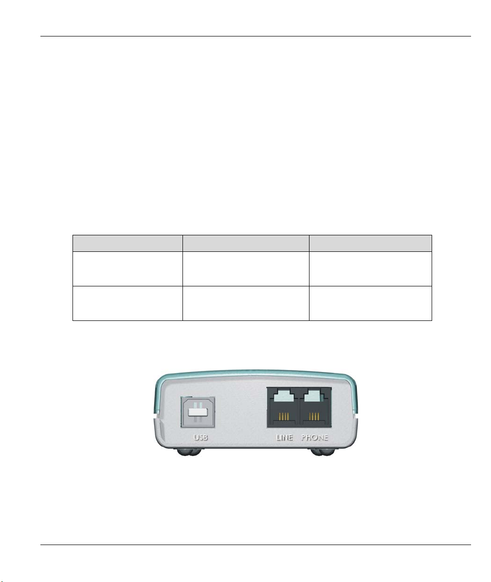
2.1.2 Back Panel
Figure 2-1 Back Panel
Installation 2-1
Page 16
Omni 56K USB Lite
Table 2-2 Back Panel Description
BACK PANEL DESCRIPTION
USB Universal Serial Bus connector that connects to a device with a
USB port, such as your computer or USB hub.
LINE Analog port RJ-11 terminal jack for connecting to a wall jack.
PHONE Analog port RJ-11 terminal jack for connecting to your phone set.
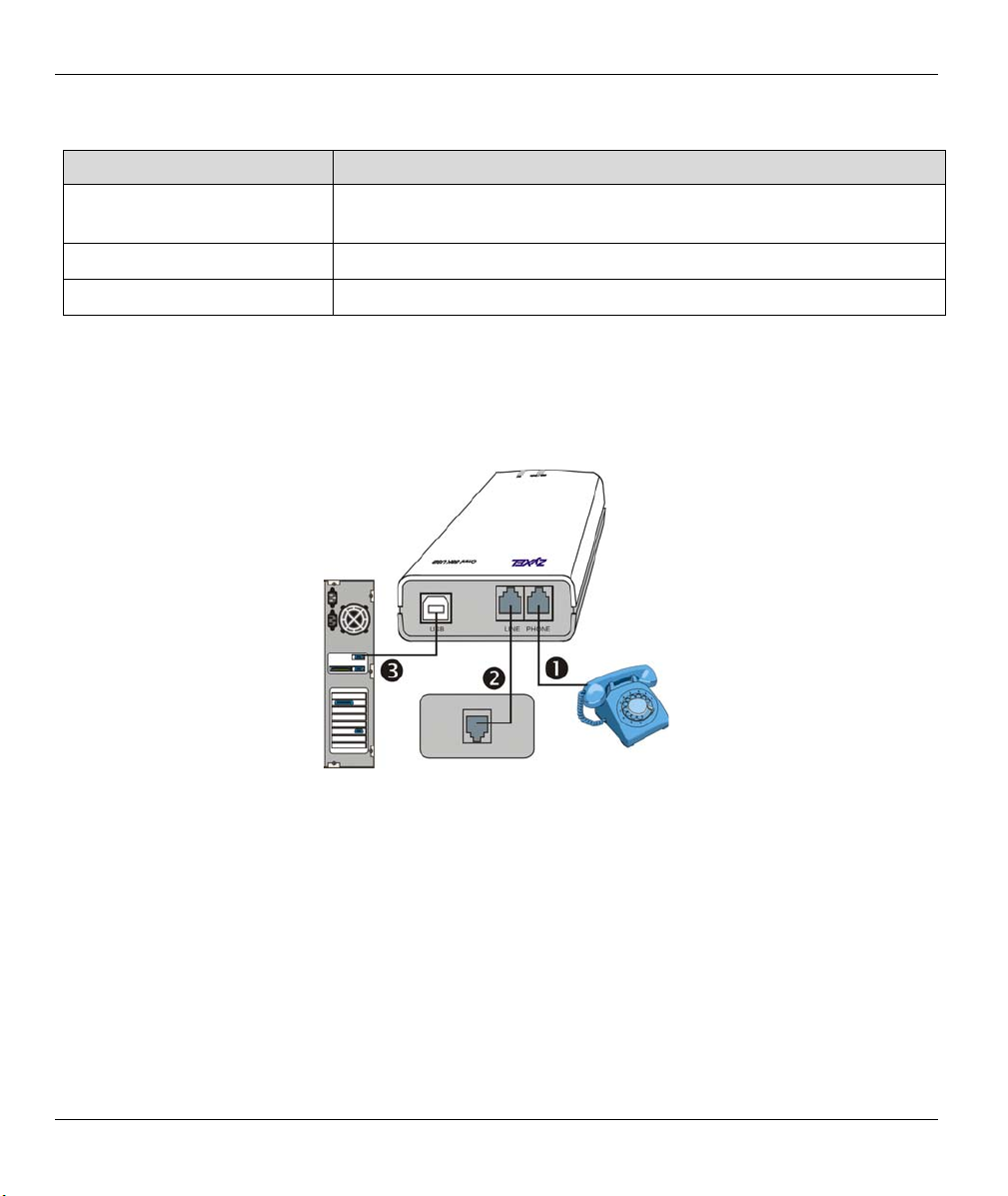
2.2 Connecting Your Omni 56K USB Lite
1. Connect your modem to your analog phone or fax.
2. Use the phone cord included to connect to the phone jack on the wall.
3. Turn on your computer and insert the included CD. Plug one end of your USB cable to your modem and
the other end to your computer’s USB port.
Figure 2-2 Connections
2.2.1 USB Connector
The Omni 56K USB Lite is an USB (Universal Serial Bus)-based modem, providing a USB connector on the
back panel of the device.
2.3 Software Installation
When you connect your Omni 56K USB Lite to the USB port of your computer, the Windows Plug and Play
function of the operating system detects if its driver has been installed. If the driver has not been installed,
Windows starts an installation wizard.
2-2 Installation
Page 17
Omni 56K USB Lite
2.3.1 Installation Wizard
You need to go through the installation wizard more than once in Windows 2000 and XP. Specify your
country specific driver in the second configuration of the installation wizard for both Windows 2000 and XP.
Follow the steps below to install your USB driver. The Windows 98 installation process is shown first,
followed by Windows 2000 and then XP.
When you connect your modem to your computer, Windows detects it and starts an installation wizard.
If Windows does not automatically start an installation wizard, unplug the USB
cable and plug it in again. If it still does not work, unplug the USB cable and restart
your computer, then plug the USB cable back in.
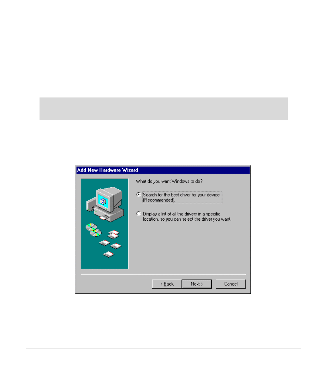
2.3.2 Windows 98
Step 1. Make sure the included CD is in your CD-ROM drive and click Next in the first screen.
Step 2. Click Next to accept the default selection.
Figure 2-3 Windows 98 Search for Driver
Installation 2-3
Page 18
Omni 56K USB Lite
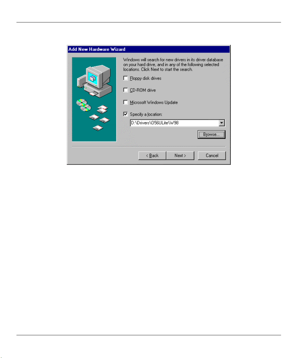
Step 3. Select Specify a location. Click Browse, select D:\Drivers\O56ULite\W98 and click Next.
Figure 2-4 Windows 98 Select Driver
2-4 Installation
Page 19
Omni 56K USB Lite
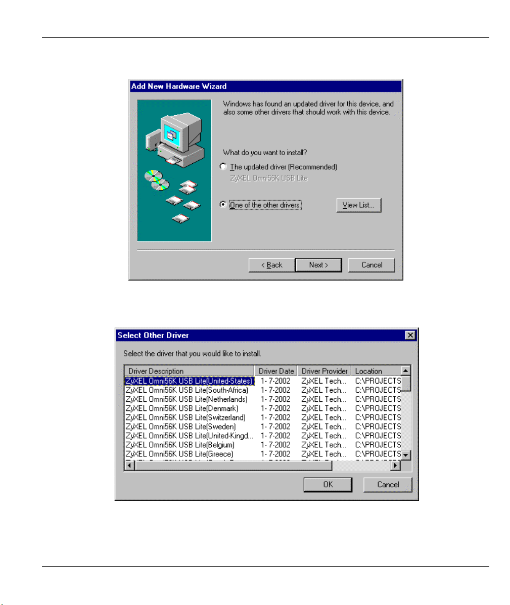
Step 4. Select the “One of the other drivers.” radio button and click View List.
Figure 2-5 Windows 98 Other Driver
Step 5. Select the driver for the country you are in (you may need to scroll down) and click OK.
Figure 2-6 Windows 98 Select Country Driver Screen
Installation 2-5
Page 20
Omni 56K USB Lite
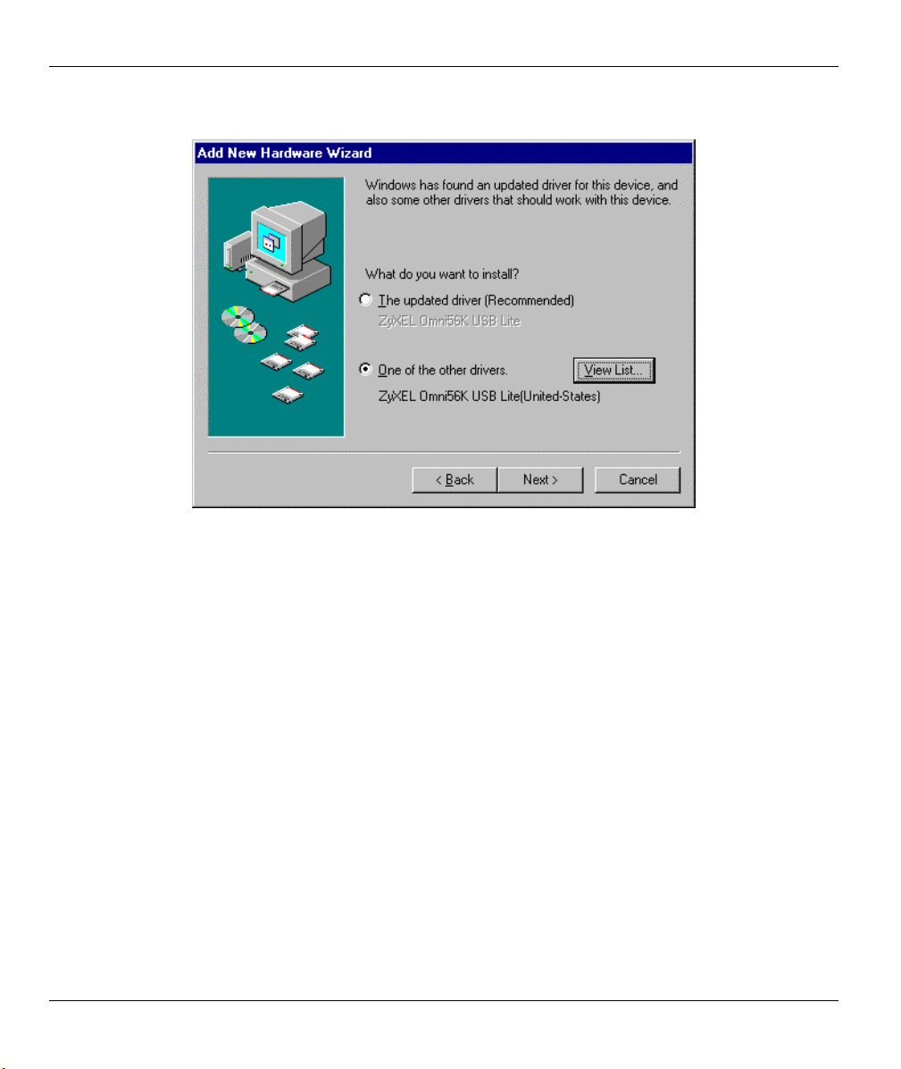
Step 6. Click Next.
Figure 2-7 Windows 98 Country Driver Selected
Step 7. Click Next in the screen that follows to have Windows copy the driver files into your system and
build the driver information database.
Step 8. After the ZyXEL USB modem has been installed, click Finish to complete the driver installation.
2-6 Installation
Page 21

Omni 56K USB Lite
2.3.3 Windows 2000
Step 1. Make sure the included CD is in your CD-ROM drive and click Next in the first screen.
Step 2. Click Next to accept the default selection.
Figure 2-8 Windows 2000 Search for Driver
Installation 2-7
Page 22
Omni 56K USB Lite
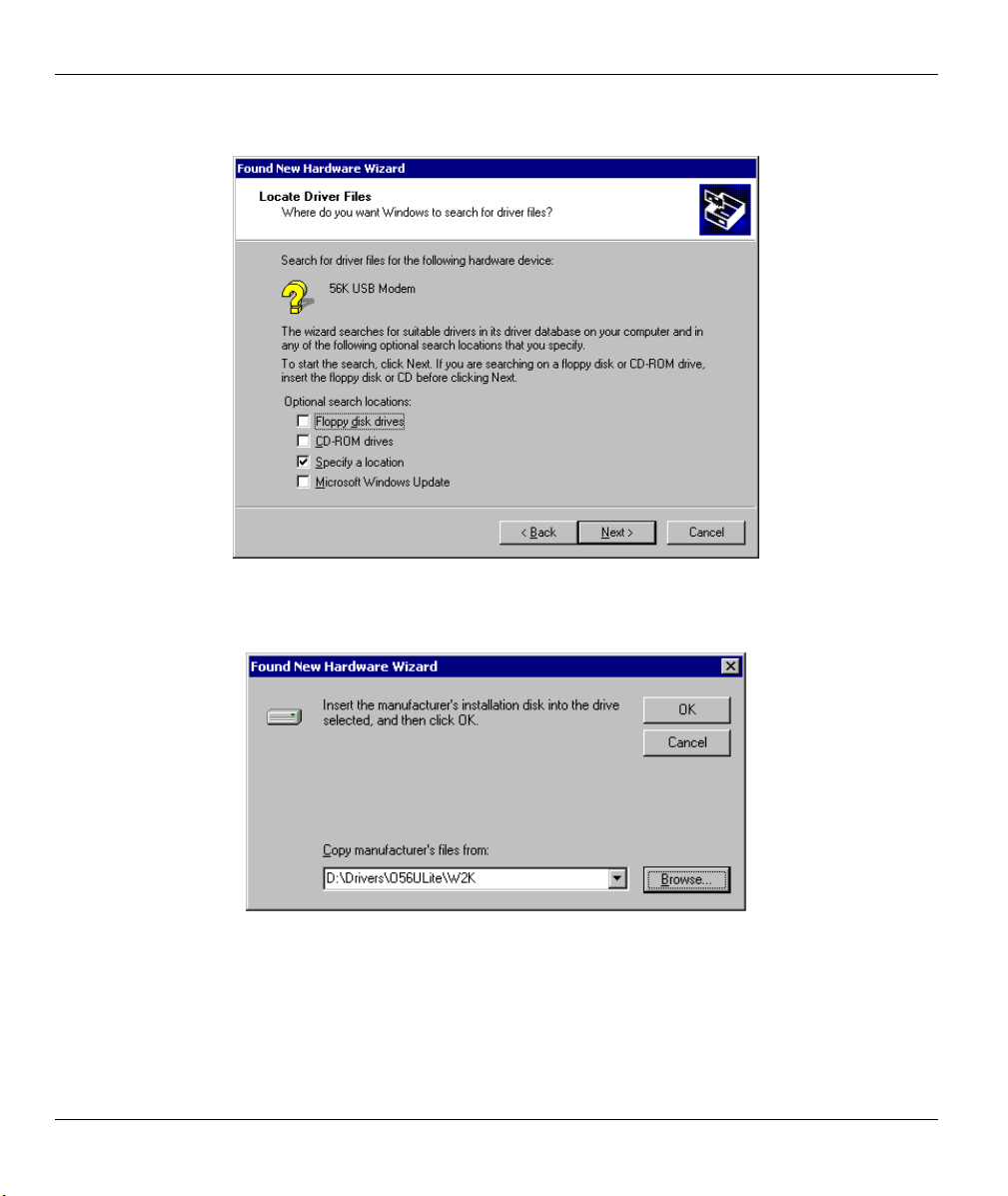
Step 3. Select Specify a location and click Next.
Figure 2-9 Windows 2000 Specify a Location
Step 4. Click Browse and select D:\Drivers\O56ULite\W2K and click OK.
Figure 2-10 Windows 2000 Select Driver
2-8 Installation
Page 23
Omni 56K USB Lite
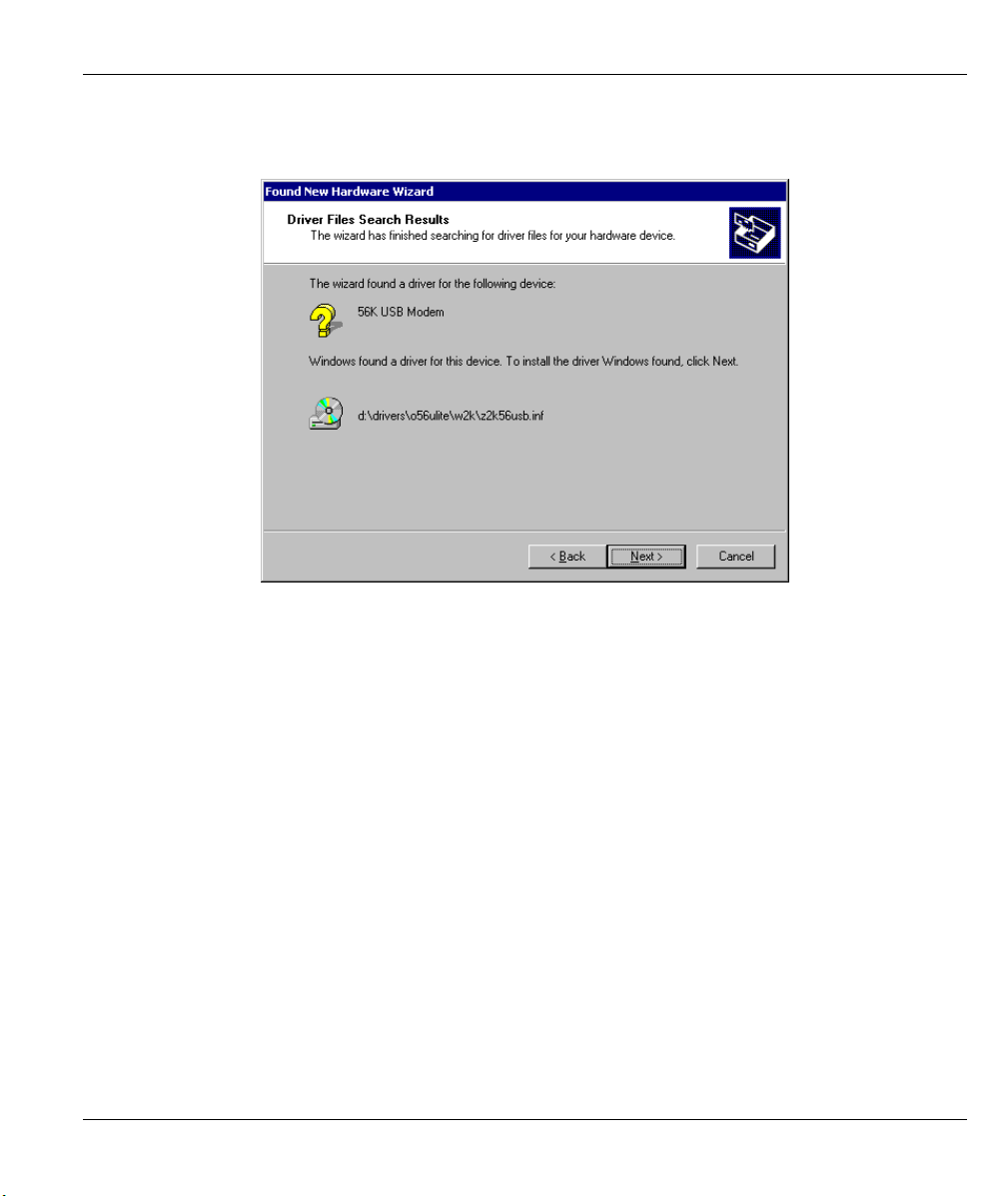
Step 5. Click Next in the screen that follows to have Windows copy the driver files into your system and
build the driver information database.
Figure 2-11 Windows 2000 Select Location
Installation 2-9
Page 24
Omni 56K USB Lite
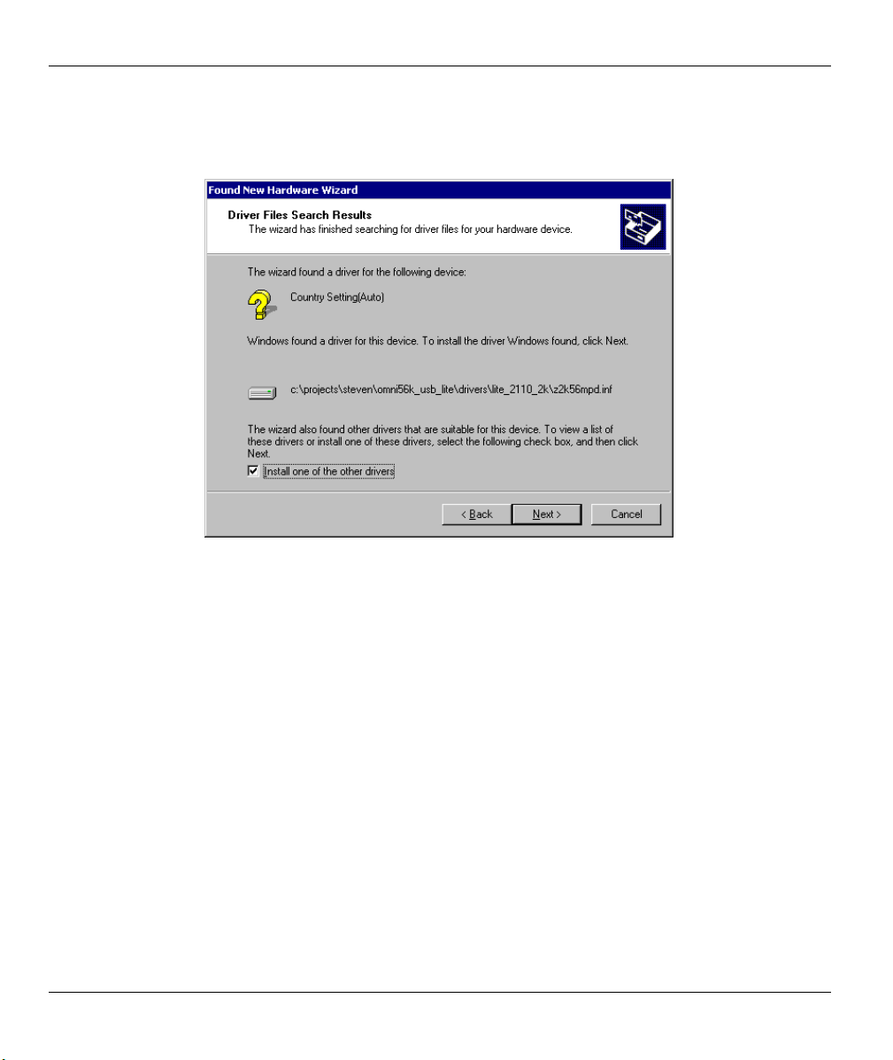
Step 6. In Windows 2000, you go through the installation wizard more than once. Use the default driver
for the first configuration (it is the only available choice). Select the “Install one of the other
drivers” checkbox during the second configuration of the installation wizard and click Next.
Figure 2-12 Windows 2000 Other Driver
2-10 Installation
Page 25
Omni 56K USB Lite
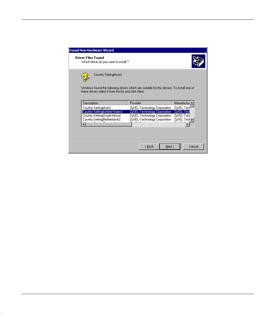
Step 7. Select the driver for the country you are in (you may need to scroll down) and click Next.
Windows copies the driver files into your system and builds the driver information database.
Figure 2-13 Windows 2000 Select Country Driver Screen
Step 8. After the ZyXEL USB modem has been installed, click Finish and follow the wizard to complete
the driver installation.
Installation 2-11
Page 26
Omni 56K USB Lite
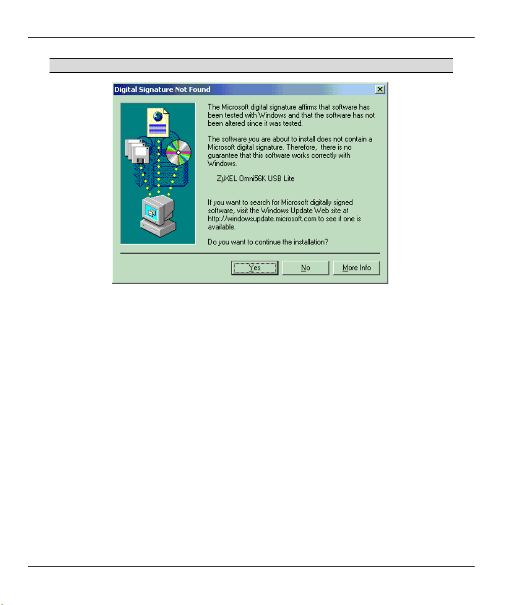
If this screen appears, click Yes to complete the installation.
Figure 2-14 Windows 2000 Digital Signature Not Found Screen
2-12 Installation
Page 27

Omni 56K USB Lite
2.3.4 Windows XP
Follow these steps to install your USB driver.
Step 1. Make sure the included CD is in your CD-ROM drive and select Install from a list or a specific
location (Advanced), then click Next.
Figure 2-15 Windows XP Specify a Location
Installation 2-13
Page 28
Omni 56K USB Lite
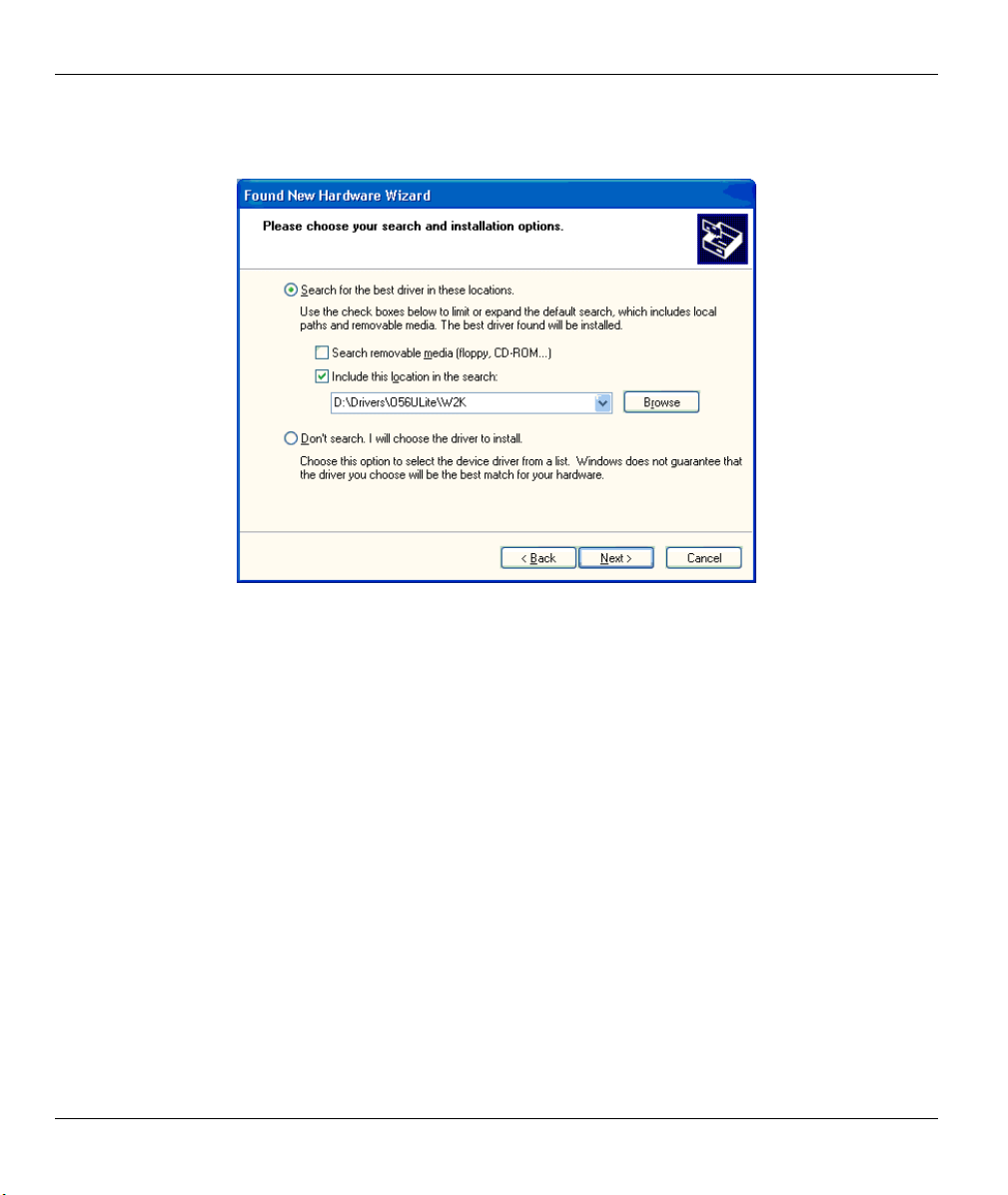
Step 2. Click Include this location in the search: and then browse for D:\Drivers\O56Ulite\W2K. Then
click Next.
Figure 2-16 Windows XP Select Driver
2-14 Installation
Page 29

Omni 56K USB Lite
If the following type of screen appears, click Continue Anyway to complete the
installation.
Figure 2-17 Windows XP Digital Signature Not Found
Installation 2-15
Page 30
Omni 56K USB Lite
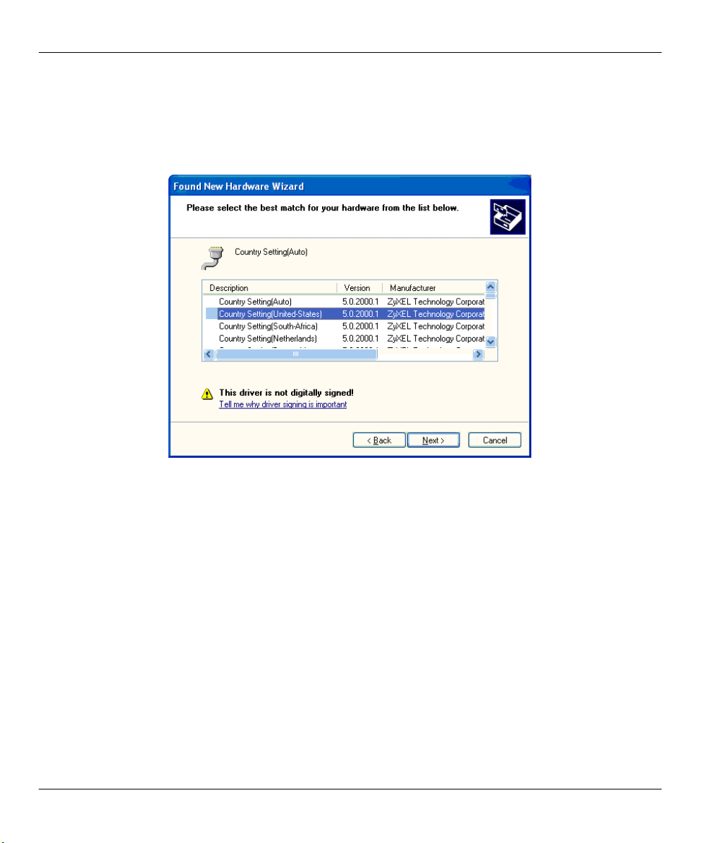
Step 3. You go through the installation wizard more than once when using Windows XP. Choose the
driver for the country you are in, during the second configuration of the installation wizard (it is
not available during the first installation wizard configuration. Select the driver (you may need to
scroll down) and click Next. Windows copies the driver files into your system and builds the
driver information database.
Figure 2-18 Windows XP Select Country Driver
Step 4. After the ZyXEL USB modem has been installed, click Finish and follow the wizard to complete
the driver installation.
2.4 Dial-up Networking
Use the connection wizard to setup your dial-up networking connection. Use the information from your ISP
to fill in the wizard screens. Windows creates an icon for your dial-up connection after you finish. Doubleclick the icon to connect to your ISP. Enter the user name and password that your ISP gave you.
Do the following to get to the connection wizard.
2.4.1 In Windows 98
Click Start, Programs, Accessories, Communications, Dial-Up Networking.
Double-click the Make New Connection icon.
2-16 Installation
Page 31

Omni 56K USB Lite
2.4.2 In Windows 2000
Click Start, Settings, Network and Dial-Up Connections, double-click Make New Connection.
2.4.3 In Windows XP
Click start, All Programs, Accessories, Communications, New Connection Wizard.
Installation 2-17
Page 32

Page 33

Omni 56K USB Lite
Chapter 3
Specifications and Functional Description
This chapter introduces the specifications and functions of the Omni 56K USB Lite. This chapter and the
next three chapters are designed for advanced users who might need more information about the Omni 56K
USB Lite's specifications and functions when programming or other applications.
3.1 Specifications
3.1.1 Hardware Specifications
Table 3-1 Hardware Specifications
ITEM SPECIFICATION DESCRIPTION
Operating Requirements Temperature: 0°C to 40°C
Humidity: 5 to 90% (non-condensing)
Weight 102g
Dimensions 75mm (W) x 100mm (H) x 25mm (L)
3.1.2 Firmware Specification
Table 3-2 Firmware Specifications
Physical layer for data mode
Specifications and Functional Description 3-1
Multi-Auto
ACPM of V.90
V.34bis 33.6 Kbps to 2.4 Kbps
V.32bis 14.4/12/9.6/7.2/4.8 Kbps
V.32 9.6/4.8 Kbps
V.23 1200/600/75 bps
V.22bis 2.4 Kbps
V.22/Bell 212 1.2 Kbps
V.21/Bell 103 300 bps
Auto Fallback/Forward
Page 34

Omni 56K USB Lite
Link layer
Flow control
Command set
Diagnostics
FAX
Voice
3.2 Protocol Support
Data Physical Layer
• ITU-T V.90
MNP 3-4 (Microcom Networking
Protocol)
MNP 5
V.42
V.42bis
V.42 SREJ
Controlled by the USB protocol
Full AT command set
Dialing type: DTMF/Pulse
Power on self-test
Analog loop-back test
Analog loop-back with self-test
V.17 G3 FAX (send and receive)
V.29 G3 FAX (send and receive)
V.27ter G3 FAX (send and receive)
EIA Class 1 Command Set
TAM function
• ITU-T V.34bis/V.34
• ITU-T V.32bis/V.32
• ITU-T V.22bis/V.22
• ITU-T V.21
• ITU-T V.23
• Bell 212A
• Bell 103
Fax Physical Layer
• ITU-T V.17
• ITU-T V.29
3-2 Specifications and Functional Description
Page 35

• ITU-T V.27ter
• ITU-T V.21
Error Control and Data Compression
• ITU-T V.42
• ITU-T V.42bis
• MNP3-5
Command Set
• Standard Command set
• EIA Class 1 Fax Command set
• Basic AT Command set
• Extended AT& Command Set
• Extended AT* Command Set
• Extended AT# Command Set
• IS101 Voice Command set
For more information on detailed command sets, please refer to Chapter 5.
Omni 56K USB Lite
3.3 Omni 56K USB Lite Capability
The data/fax/voice feature of the Omni 56K USB Lite is described in the following table:
Specifications and Functional Description 3-3
Page 36

Omni 56K USB Lite
Table 3-3 Data/Fax/Voice Feature Description
FEATURE DESCRIPTION
Data .2W Dial-Up Line
.Multi-auto/V.90/V.34/V.32bis/V.32/V.23/V.22bis/V.22/Bell212A/V.21/Bell 103
.USB Flow Control
.Error Control/Data Compression
.ZyXEL AT Command Set
.External Plug and Play for Windows® 98/2000/XP in USB mode
.Repeat Dial/Cyclic Dial
.Caller ID
.Distinctive Ring
.AT Protection for software application
Fax .V.17/V.29/V.27ter
.G3 T.30 Protocol
.EIA Class 1 Command Set
Voice .TAM function
3.3.1 Data Function
Physical Layer Capability
The Omni 56K USB Lite is a high performance universal modem capable of transmission speeds up to
56/33.6 Kbps full duplex on a 2-wire dial-up line. Universal compatibility covers a broad range of ITU-T and
BELL standards.
Table 3-4 Physical Layer Capacity
STANDARD BIT RATE
[BPS]
BAUD RATE
[BAUD]
MODULATION CARRIER
FREQUENCY [HZ]
V.90 28000-56000 8000 PCM 0
V.34 2400-33600 multiple TCM multiple
V.32bis 14400 2400 128-TCM 1800
V.32bis 12000 2400 64-TCM 1800
V.32bis 9600 2400 1800
V.32bis 7200 2400 16-TCM 1800
3-4 Specifications and Functional Description
Page 37

Omni 56K USB Lite
STANDARD BIT RATE
[BPS]
BAUD RATE
[BAUD]
MODULATION CARRIER
FREQUENCY [HZ]
V.32bis 4800 2400 1800
V.32 9600 2400 32-TCM 1800
V.32 uncoded 9600 2400 16-QAM 1800
V.32 4800 2400 4-DPSK 1800
V.23 1200/75 1200/75 FSK
V.23 600/75 600/75 FSK
V.22bis 2400 600 16-QAM 1200 Call
2400 Ans
V.22 (BELL 212) 1200 600 4-DPSK 1200 Call
2400 Ans
V.21 (BELL 103) 300 300 FSK
Error Control
Error control keeps the modem data link error-free by detecting and re-transmitting erroneous data. The
Omni 56K USB Lite supports both MNP and V.42 error control protocols. The MNP protocol was an
industry standard developed and licensed by Microcom, Inc. The Omni 56K USB Lite supports level 4 and 3
error control protocols, commonly denoted as MNP4 and MNP3.
V.42 is a standard developed by CCITT (Consultative Committee for International Telephony and
Telegraphy). V.42 supports both LAPM (Link Access Procedure for Modems) and MNP4. A V.42
handshaking tries an LAPM connection first, and if not successful, it tries MNP4.
Data Compression
In the modem, the data compression is activated in an attempt to reduce the number of bits actually sent. The
receiving modem applies these techniques in reverse to recover the actual data from the compressed data
stream.
The Omni 56K USB Lite supports both V.42bis and MNP5 data compression protocols. Data compression
needs an error-free data link to work correctly, otherwise the corrupted compressed data stream ruins the
decompression process. MNP5 is used with MNP4 error control and V.42bis is used with V.42 error control.
The compression efficiency of V.42bis is generally higher than that of MNP5. In some cases, V.42bis can be
50% to 100% higher and in other cases it is just slightly higher. In general, it is about 50% more efficient.
Specifications and Functional Description 3-5
Page 38

Omni 56K USB Lite
Repeat Dial
The modem dials the default number stored in the Windows’ registry repeatedly if not connected.
(s38.0=1,*Dn)
Cyclic Dial
Dial the number stored in the registry at location n (0 to 3) if cyclic dial s44.3=1 is set.
If the first dial is not successful, the modem cycles dial through the four numbers stored in the registry.
Caller Number Delivery (Caller ID)
Caller Number Delivery (CND), commonly called Caller ID, is a phone service that may be offered by your
local phone company. Check your phone company for availability. You must subscribe to it and usually pay
an additional monthly service charge for this service.
With CND service, the phone company's central office sends the coded caller information to the called
station. This information is sent once between the first and second ring. Your modem can decode this caller
information and present it to the connected computer/terminal during the second ring period as part of the
call progress ring message. The modem also reports the Caller ID information if asked by the command
AT*T.
There are two kinds of caller information message formats sent by the phone company.
One is the single message format that includes date, time, and caller ID.
The other is the multiple message format which also includes the caller name as registered with the
phone company.
The command ATS40.2=n is used to enable (n=1) or disable (n=0) the Caller ID detection function. The
default is disabled. Enable it only when you have this service and want to enable its detection.
The Caller ID message may cause some communication software that is not
expecting it to become confused. If you plan to use the Caller ID feature, be sure
you are using software that supports it.
In single message format, the modem sends a ring message to the terminal as follows:
RING
TIME: <MM-DD hh:mm>
CALLER NUMBER: <CALLER_ID> or CALLER NAME:<CALLER_NM>
RING
MM is the two-digit month message, DD is the two-digit date message, hh is the hour and mm is the minute
of the time, and CALLER_ID is the phone number of the caller or CALLER_NM his/her name.
3-6 Specifications and Functional Description
Page 39

Omni 56K USB Lite
The following is an example of a caller ID message as it might appear on your screen:
RING
TIME: 04-28 12:30
CALLER NUMBER: 7135551414 or CALLER NAME: John Doe
RING
In the multiple message format, if the caller's number and name are available, the ring message displays both:
RING
TIME: MM-DD hh:mm
CALLER NUMBER: <Caller_ID>
CALLER NAME: <Caller_Name>
RING
Here is an example:
RING
TIME: 04-28 12:30
CALLER NUMBER: 7135551414
CALLER NAME: Tracy Huang
RING
If the caller number and name are not available, the ring message appears as follows:
RING
TIME: 04-28 12:30
REASON FOR NO NUMBER: OUT_OF_AREA
REASON FOR NO NAME: PRIVACY
RING
The last CND message that the modem received can be displayed by using the AT*T command.
Setting S48.0=1 causes the modem to report CND information in its ASCII coded hexadecimal raw data
format. The DTE software is responsible for explaining the data.
Specifications and Functional Description 3-7
Page 40

Omni 56K USB Lite
Please refer to the Bellcore Technical Advisory document TR-NWT-000030 for
the exact data format. The above Caller ID scheme applies to the North America
area. Different countries may employ different Caller ID schemes, check if the
scheme used in your country is supported before using the Caller ID feature. For
most other Caller ID schemes, only the Caller telephone number is provided.
Distinctive Ring
Distinctive Ring is a phone service that may be offered by your phone company. Check your phone company
for availability. With this service, you can have several phone numbers assigned to the same phone line. The
phone company sends a different type of ring signal for each phone number being called. The subscriber can
distinguish which number is called by which type of ring is received.
One benefit of this feature is the ability to have three numbers on the same line allowing you to list the three
numbers for voice, data, and fax, respectively. You can then have your fax machine answer only the ring
corresponding to the fax number and have your modem answer only the ring corresponding to the data
number. A voice call is not answered by either fax machine or data modem and it is answered only by
picking up the phone. You can also have the answering machine answer only the voice ring. A more
complicated use is that you can have one number for multiple uses, such as one number for both data and fax.
A ring signal is a composition of repeated on and off states. Different types of rings usually correspond to
different compositions of the "on" part (cadence) of the ring. Your modem can distinguish up to four types of
ring signals and can be commanded to answer or not answer any one of these four types of ring signals.
Following is a list of these four types of ring signals. These are the ring types used in the USA. The
difference among the ring types is the two-second ON part of the ring signal. It comprises a long, double
short, or triple short ring.
S-register S40 bits 3-6 are used for distinctive ring control. Each bit controls the answering of a particular
ring type. Setting a bit to "1" enables answering, setting it to "0" rejects the ring. Note that the ring may still
be heard even if it is not counted as an accepted ring by the modem.
The control relationships between bits 3 to 6 in register S40 and the different ring types are:
Table 3-5 Different Ring Types in Register S40
TYPE BIT (ON) RING SEQUENCE
1 3 1.2s or 2s on; 4s off
2 4 0.8s on, 0.4s off, 0.8s on; 4s off
3 5 0.4s on, 0.2s off, 0.4s on, 0.2s off, 0.8s on; 4s off
4 6 0.3s on, 0.2s off, 1s on, 0.2s off, 0.3s on; 4s off
3-8 Specifications and Functional Description
Page 41

3.3.2 Fax Function
Fax Physical Layer Protocol
Omni 56K USB Lite
Table 3-6 Fax Physical Layer Capacity
STANDARD BIT RATE
[BPS]
BAUD RATE
[BAUD]
MODULATION CARRIER FREQUENCY
[HZ]
V.17 14400-7200 2400 TCM 1800
V.29 9600-4800 2400 QAM/DPSK 1700
V.27ter 4800-2400 1600/1200 PSK/DPSK 1800
EIA (Electronic Industries Association) Class 1 Command Set
Please refer to Fax Command Set in Chapter 5.
ITU-T T.30 Fax Protocol
The ITU-T T.30 fax protocol is known as the G3 fax handshake signals and procedures. The modem takes
full control of this protocol - initiating and terminating fax calls, managing the communication session, and
transporting the image data. Therefore, the modem relieves the computer fax software of the T.30 protocol
handling.
Your modem allows for fax speeds up to 14400 bps when transmitting to a fax machine which complies with
the V.17 fax standard. Speeds fall back to 12000, 9600, or 7200 bps in poor line conditions. When
connecting to a G3 fax device, your modem allows for fax speeds up to 9600 bps and automatically falls
back to 7200, 4800, and 2400 bps if the line quality is poor.
3.3.3 Voice Function
Voice capability stands for the modem's ability to digitize incoming voice messages, which the computer
stores and forwards. It also means that the modem can playback the recorded digitized voice on line for a
message announcement.
Voice IS-101 Command Set
Please refer to the Voice command sets in Chapter 5.
4-bit Voice Data Compression
The main issue in the digitized voice mode is the amount of storage required. A relatively simple ADPCM
algorithm can reduce the speech data rate to half the rate and maintain about the same voice quality. This
algorithm can also be used to reduce the speech data rate to 1/3 or 1/4 of the original rate, but with voice
quality degradation. Only 4-bit ADPCM is used in the Omni 56K USB Lite.
Specifications and Functional Description 3-9
Page 42

Page 43

Omni 56K USB Lite
Chapter 4
Result Codes
4.1 Result Codes
The result code is the command response or the Connect message to the DTE. The format of the result code
is dependent on Xn and Vn commands. The lists are as follows:
Table 4-1 Result Codes
RESULT CODE FOR
ATV0 ATV1
0OK 00000000
1CONNECT 00000XXX
2RING 00000000
3NO CARRIER 00000000
4ERROR 00000000
5CONNECT 1200 0000XXX
6NO DIAL TONE 0 0000
7BUSY 00000
8NO ANSWER 00000
9RINGING 00000
10CONNECT 2400 0000XXX
11CONNECT 4800 0000XXX
12CONNECT 9600 0000XXX
14CONNECT 19200 0000XXX
15CONNECT 7200 0000XXX
X0 X1 X2 X3 X4 X5 X6 X7
16CONNECT 12000 0000XXX
Result Codes 4-1
Page 44

Omni 56K USB Lite
RESULT CODE FOR
ATV0 ATV1
X0 X1 X2 X3 X4 X5 X6 X7
17CONNECT 14400 0000XXX
18CONNECT 16800 0000XXX
19CONNECT 38400 0000X
20CONNECT 57600 0000X
21CONNECT 76800 0000X
22CONNECT 115200 0000X
23CONNECT 230400 0000X
24CONNECT 460800 0000X
25CONNECT 921600 0000X
26CONNECT 307200 0000X
27CONNECT 153600 0000X
28CONNECT 102400 0000X
29CONNECT 61440 0000X
30CONNECT 51200 0000X
31CONNECT 624000 00000
32CONNECT 124800 00000
33CONNECT 62400 0000X
34CONNECT 41600 0000X
35CONNECT 31200 0000XXX
36CONNECT 24960 0000X
37CONNECT 20800 0000X
38CONNECT 33600 0000XXX
39CONNECT 28800 0000XXX
40CONNECT 26400 0000XXX
4-2 Result Codes
Page 45

Omni 56K USB Lite
RESULT CODE FOR
ATV0 ATV1
X0 X1 X2 X3 X4 X5 X6 X7
41CONNECT 24000 0000XXX
42CONNECT 21600 0000XXX
100CONNECT 56000 0000XXX
101CONNECT 54666 0000XXX
102CONNECT 53333 0000XXX
103CONNECT 52000 0000XXX
104CONNECT 50666 0000XXX
105CONNECT 49333 0000XXX
106CONNECT 48000 0000XXX
107CONNECT 46666 0000XXX
108CONNECT 45333 0000XXX
109CONNECT 44000 0000XXX
110CONNECT 42666 0000XXX
111CONNECT 41333 0000XXX
112CONNECT 40000 0000XXX
113CONNECT 38666 0000XXX
114CONNECT 37333 0000XXX
115CONNECT 36000 0000XXX
116CONNECT 34666 0000XXX
117CONNECT 33333 0000XXX
118CONNECT 32000 0000XXX
119CONNECT 30666 0000XXX
120CONNECT 29333 0000XXX
121CONNECT 28000 0000XXX
Result Codes 4-3
Page 46

Omni 56K USB Lite
If error control result codes are enabled (X4, X5, X6, X7), the resulting message is
formatted as the following:
X4: CARRIER Rx Rate.
PROTOCOL: Error Control Level
COMPRESSION: Compression Level
CONNECT DTE Speed
X5: CONNECT DTE Speed/Protocol Rx Rate/Error Control Level
X6: CONNECT Rx Rate/ARQ
X7: CONNECT Rx Rate/ARQ/Error Control Level
Where ARQ denotes that Automatic Retransmission reQuest type of error control is enabled.
4-4 Result Codes
Page 47

Omni 56K USB Lite
Chapter 5
Command Sets
This chapter lists the command set the Omni 56K USB Lite supports. These commands include data
command sets, fax command sets and voice command sets.
5.1 Data Command Sets
5.1.1 Basic AT Command Sets
Table 5-1 Basic AT Command Sets
COMMAND OPTIONS FUNCTION AND DESCRIPTION REF.
A/ Re-execute the last command once.
A> Re-execute the last command once or repeat
the last call up to 9 times. (See also S8)
<any key> Terminate the current connection attempt when
entered in handshaking state.
+++ Escape sequence code, entered in data state,
wait for modem to return to online command
mode.
All of the following commands require an "AT" prefix:
Table 5-2 AT Command Sets Requiring an "AT" Prefix
COMMAND OPTIONS FUNCTION AND DESCRIPTION REF.
A Go online in answer mode. (See also S39.2, S43.6).
Bn
B0 * Select CCITT V.22 for 1200 bps.
B1 Select Bell 212 for 1200 bps communication.
Command Sets 5-1
Handshake option: S28.7
Page 48

Omni 56K USB Lite
COMMAND OPTIONS FUNCTION AND DESCRIPTION REF.
Ds
Dial s (numbers and options) that follow (see also S38.0,
S35.4). The options of s are listed as follows:
0-9, A, B,
Digits for dialing.
C, D #, *
P Pulse dialing. S23.1
T Tone dialing. S23.1
, Pause for a time specified in S8. Remaining digits are dialed
as in-band DTMF (Dual Tone Multi-Frequency).
; Return to command state after dialing.
! Hook flash. S56
R Reverse handshake (go online in Answer mode). S17.5
W Wait for the second dial tone. Remaining digits are dialed as
in-band DTMF.
DL Dials the last-dialed number.
DSn n=0-3 Dials the number stored in the Windows registry at location 'n.' S44.3
En
Command mode local echo of keyboard commands: S23.0
E0 Echo off.
E1 * Echo on.
Hn
On/off hook control:
H0 * Hang up (on-hook) the modem or ISDN, same as 'ATH'.
H1 Off hook the modem.
In
Display inquired information:
I0 Display numerical product code, same as 'ATI.'
I1 Display product information and ROM checksum.
I2 Display modem link status report.
I12 Display physical layer status.
I13 Display channel response for V.34.
5-2 Command Sets
Page 49

Omni 56K USB Lite
COMMAND OPTIONS FUNCTION AND DESCRIPTION REF.
Ln n=0 to 3
2 *
Mn
Speaker volume control. The higher the value, the higher the
volume.
Speaker control: S21.1-2
M0 Speaker is always OFF.
M1 * Speaker is ON until carrier is detected.
M2 Speaker is always ON.
M3 Speaker is ON after the last digit is dialed out. Tone dialing is
not heard.
O Return to online state.
O1 Force modem to request a retrain.
Qn
Result code displayed: S23.7
Q0 * Modem returns result code.
Q1 Modem does not return result code.
Q2 Modem returns result code but quiet after answering on a
RING. (see also S42.2)
Sr.b=n Set bit 'b' of S-register 'r' to value 'n'. 'n' is a binary digit '0' or
'1'.
Sr.b? Display value of bit 'b' of S-register 'r'.
S24.4-6
S40.1
Sr=n Set S-register 'r' to value 'n'. 'n' must be a decimal number
between 0 and 255.
Sr? Display value stored in S-register 'r'.
T Tone dial. S23.1
Vn
Sets display type for Result Codes: S23.6
V0 Display result code in numeric form. (See also S35.7 and the
result code table of 'ATXn'.)
V1 * Display result code in verbose form.
Xn n=0-7
Result code options, see the Options Table. S23.3-5
5 *
Command Sets 5-3
Page 50

Omni 56K USB Lite
COMMAND OPTIONS FUNCTION AND DESCRIPTION REF.
Zn
n=0-2 Reset modem and set power-on profile. S15.5-7
Zn Reset modem and load user profile n (0-1).
Z2 Reset modem and load factory settings.
+++ Escape sequence code, entered in data state, wait for modem
to return to command state.
5.1.2 Extended AT& Command Sets
Table 5-3 Extended AT& Command Set
COMMAND OPTIONS FUNCTION AND DESCRIPTION REF.
&Cn
&C0 CD always ON (See also S42.7).
&C1 * CD tracks presence of carrier (See also S38.3, S42.7).
&Dn
&D0 Ignore DTR signal, assume DTR is always ON.
&D1 108.1, DTR OFF-ON transition causes dial of the default
Carrier Detect (CD) options: S21.4
Data Terminal Ready (DTR) options. (See also S25): S21.6-7
number. (See also 'AT*Dn' and S48.4).
&D2 * 108.2, Data Terminal Ready, DTR OFF causes the
modem to hang up.
&D3 Same as &D2 but DTR OFF causes the modem to hang
up and reset from profile 0.
&F Load factory settings to RAM as active configuration.
&Gn
Guard tone options: S28.4-5
&G0 * No guard tone (within USA, Canada).
&G2 1800 Hz guard tone.
5-4 Command Sets
Page 51

Omni 56K USB Lite
COMMAND OPTIONS FUNCTION AND DESCRIPTION REF.
&Kn
&Nn
Modem error control and data compression: S27.0-2
&K0 No error control. (Same as AT&K).
&K1 MNP4 (See also S41.0), (include MNP3).
&K2 MNP4+MNP5 (See also S38.5, S41.0).
&K3 V.42+MNP4.
&K4 * V.42+V.42bis, compatible with &K2 (See also S38.5).
Modem link mode options (DCE/DCE). (See also S43.7,
S48.1):
&N0 * Multi-Auto, auto-negotiate highest possible link rate:
V.90, V.34, V.32bis, V.32, V.23, V.22bis, V.22 and Bell
212, V.21 Bell 103, G3 Fax V.17/V.29/V.27ter.
&N3 V.32bis 12000T/9600/7200T/4800
&N4 V.32 9600/4800
&N5 V.32 4800
&N12 V.23 1200/75
&N13 V.23 600/75
&N14 V.22bis 2400
&N15 V.22 1200
S19
&N16 V.21 300
&N17 V.32bis 14400/12000/9600/7200/4800
&N18 V.32bis 12000/9600/7200/4800
&N19 V.32bis 7200/4800
&N24 BELL 212 1200
Command Sets 5-5
Page 52

Omni 56K USB Lite
COMMAND OPTIONS FUNCTION AND DESCRIPTION REF.
&Nn
&N25 BELL 103 300
&N60 V.34 33600
&N61 V.34 31200
&N62 V.34 28800
&N63 V.34 26400
&N64 V.34 24000
&N65 V.34 21600
&N66 V.34 19200
&N67 V.34 16800
&N68 V.34 14400
&N69 V.34 12000
&N70 V.34 9600
&N71 V.34 7200
&N72 V.34 4800
&N73 V.34 2400
&N99 V.90 28000
&N98 V.90 29333
&N97 V.90 30666
&N96 V.90 32000
&N95 V.90 33333
&N94 V.90 34666
&N93 V.90 36000
&N92 V.90 37333
&N91 V.90 38666
5-6 Command Sets
Page 53

Omni 56K USB Lite
COMMAND OPTIONS FUNCTION AND DESCRIPTION REF.
&Nn
&Pn
&Rn
&N90 V.90 40000
&N89 V.90 41333
&N88 V.90 42666
&N87 V.90 44000
&N86 V.90 45333
&N85 V.90 46666
&N84 V.90 48000
&N83 V.90 49333
&N82 V.90 50666
&N81 V.90 52000
&N80 V.90 53333
&N79 V.90 54666
&N78 V.90 56000
Pulse dial make/break ratio: S23.2
&P0 * Make / break=39% / 61%.
&P1 Make / break=33% / 67%.
RTS (Request To Send) function selection: S21.5
&R0 CTS tracks RTS, response delay is set in S26.
&R1 * Ignore RTS, assumes RTS always ON.
&Sn
Data Set Ready (DSR) function selection: S21.3
&S0 * DSR overridden, DSR always ON.
&S1 DSR according to CCITT (ITU-TSS). (See also S41.5,
S44.4).
Command Sets 5-7
Page 54

Omni 56K USB Lite
COMMAND OPTIONS FUNCTION AND DESCRIPTION REF.
&Tn
Modem testing: S16
&T0 Terminate test in progress.
&T1 Initiate Analog Loop-back (ALB) test.
&T8 Initiate Analog Loop-back with self-test (ALB+ST).
&Vn
View profile settings:
&V0 View current active settings.
&Vn View the (n-1) user profile settings (n=1-2).
&V3 View factory default settings.
&Wn n=0-1 Save current settings to user profile n in the Windows
registry (see also S35.6).
&Yn
Break handling. Destructive Break clears the buffer.
Expedited Break is sent immediately to the remote
system:
&Y0 Destructive, expedited.
&Y1 * Non-destructive, expedited.
&Y2 Non-destructive, unexpedited.
&Z? Display all the phone numbers stored in the Windows
registry.
S28.2-3
&Zn=s n=0 to 3 Store phone number/s to the Windows registry at
location n (n=0 to 3) use AT*Dn or ATS29=n to set the
default dial pointer.
5.1.3 Extended AT* Command Sets
Table 5-4 Extended AT* Command Sets
COMMAND OPTIONS FUNCTION AND DESCRIPTION REF.
n=0 to 3 Set default dial pointer at telephone directory location 'n.' S29*Dn
*D0 * (See also S35.4 and S38.0).
5-8 Command Sets
Page 55

Omni 56K USB Lite
COMMAND OPTIONS FUNCTION AND DESCRIPTION REF.
*En
*E0 * If error control negotiation fails, keep the non-error
*E1 If error control negotiation fails, disconnect the call (hang-
*Pn n=0 to 15
*P9 *
*Qn
*Q0 No action to poor signal quality.
*Q1 Retrain action taken if signal quality is poor (see also
*Q2 * Adaptive rate, automatic fall-back or forward.
*Q3 Disconnect if signal quality is poor.
*T Recall the last CND (Caller ID) information. S40.2
Modem error control negotiation: S21.0
control connection.
up).
Set transmission power level; ranges from -8 dBm to -15
dBm (default: -11 dBm).
Action taken when line quality changes: S27.6-7
S41.2).
S17.1-4
5.1.4 Extended AT# Command Sets
Table 5-5 Extended AT# Command Sets
COMMAND OPTIONS FUNCTION AND DESCRIPTION REF.
#En Modem status in escape state:
#E0 Disable the report of modem status in escape state.
#E1 Enable the report of modem status in escape state.
5.2 Fax Command Sets
5.2.1 Service Class 1 Commands
Command Sets 5-9
Page 56

Omni 56K USB Lite
COMMAND DESCRIPTION VALUE
Table 5-6 Service Class 1 Commands
+FCLASS=n Service Class Identification
and Control.
n=0: Sets to modem mode
n=1: Sets to Class 1 mode
n=8: Sets to Voice mode
+FTS=n Stop transmission and pauses. n=0 to 255 in 10 ms units
+FRS=n Wait for Silence. n=0 to 255 in 10 ms units
+FTM=<MOD> Transmit Data with <MOD>
See table 16
Carrier.
+FRM=<MOD> Receive Data with <MOD>
See table 16
Carrier.
+FTH=n Transmit HDLC Data with
n=3
<MOD>=3 Carrier.
+FRH=n Receive HDLC Data with
n=3
<MOD>=3 Carrier.
The value of <MOD> parameters are listed in the following table:
Table 5-7 The Value of <MOD> Parameters
VALUE MODULATION SPEED
3 V.21 ch 2 300
24 V.27ter 2400
48 V.27ter 4800
72 V.29 7200
73 V.17 7200
74 V.17 short train 7200
96 V.29 9600
97 V.17 9600
98 V.17 short train 9600
121 V.17 12000
5-10 Command Sets
Page 57

Omni 56K USB Lite
VALUE MODULATION SPEED
122 V.17 short train 12000
145 V.17 14400
146 V.17 short train 14400
5.2.2 Voice AT Commands
Table 5-8 Voice AT Commands
COMMAND FUNCTION OPTION DEFAULT DESCRIPTION
+VIP Initialize
N/A N/A +VSD=70, 70 (70, 7 second)
parameters
+FCLASS Voice/data/
0, 1, 8 0 0: DATA.
fax selection
+FMI? ManufacturerIDN/A ZyXEL
+FMM? Model ID N/A Omni
56K USB
Lite
+FMR? Revision N/A Vx.xx
+VRX Voice
N/A N/A Start recording.
Recording
+VLS Select a voice
0, 2 0 0: The DCE is on-hook. Local phone
I/O device
+VTD=100 (1 second)
+VRN=10 (10 second)
+VRA=70 (7 second)
+VIT=70 (7 second)
1: CLASS 1 FAX.
2.0: CLASS 2.0 FAX.
8: VOICE.
connected to Telco line.
2: The DCE is off-hook and is
connected to the phone line. The local
phone is provided with power. The
modem can record/play through the
local telephone line.
Command Sets 5-11
Page 58

Omni 56K USB Lite
COMMAND FUNCTION OPTION DEFAULT DESCRIPTION
+VRA Ring back
goes away
timer
+VRN Ring back
never come
timer
+VTX Voice
transmit
mode
+VSD Silence
detection
+VSM Select
compression
method
0 to 255 70 0: turn off the timer.
1 to 255: Defines the period without
ringback (after at lease one ringback
has been detected) in 100 ms units.
0 to 255 10 0: turn off the timer.
1 to 255: Defines the period without
ringback after dialing in 1 sec unit.
N/A N/A Switches to voice transmit mode.
Threshold,
Period
(0 to 255), (0 to
255)
70, 70 Threshold:
0: Disable silence detection.
1 to 255: The smaller the value, the
more sensitive to the silence detection
it is.
Period:
1 to 255: The required period of
silence detection before DCE
reporting the silence event.
0: Disable silence detection.
Unit: 0.1 second.
4; ZyXEL
ADPCM; 4 Bit;
(9600)
4, 9600 IMA 4 bit ADPCM. (4: DigiSpeech
IMA; 5: DVI Intel IMA)
Sample rate: 9600/8000.
+VTS= [x,
y, z]
Dual Tone
Generation
x: 0 to 3000 Hz
y: 0 to 3000 Hz
z: 0 to 1000
N/A x: first tone frequency.
y: second tone frequency.
z: duration in 10ms unit.
(10ms)
+VTS= {x,y}DTMF Tone
Generation
x: 0 to 9, *, #, A
to D
N/A x: DTMF digits (0 to 9, *, #, A, B, C, D)
y: duration in 10ms unit.
y: 0 to 1000
(10ms)
+VTS= x,
x…
DTMF Tone
Generation
x: 0 to 9, *, #, A
to D
N/A x: DTMF digits (0 to 9, *, #, A, B, C, D)
Duration: +VTD setting (in 10ms unit).
5-12 Command Sets
Page 59

Omni 56K USB Lite
COMMAND FUNCTION OPTION DEFAULT DESCRIPTION
+VTD Set default
duration of
DTMF tone
+VIT Inactivity
timer
1 to 255 100 Unit: 0.01 second.
0 to 255 70 Unit: 0.1 second.
5.2.3 Voice Shielded DTE Commands
Table 5-9 Voice Shielded DTE Commands
COMMAND DESCRIPTION
<DLE>p Pause: suspend voice data to the output device in playback state.
<DLE>r Resume: resume suspended voice data in playback state.
<DLE><ETX> Terminate voice playback state: switch to online voice command mode after
completing remaining data in buffer.
5.2.4 Voice Shielded DTE Responses
Table 5-10 Voice Shielded DTE Responses
RESPONSE CODE DESCRIPTION
<DLE>0 - <DLE>9
<DLE>*, <DLE>#
<DLE>A - <DLE>D
DTMF digit detected.
<DLE>a Answer Tone detected.
<DLE>b Busy detected.
<DLE>c Calling Tone detected.
<DLE>d Dial Tone detected.
<DLE>e European Data Modem Calling Tone detected.
<DLE>f Bell Answer Tone detected.
<DLE>q Quiet detected.
<DLE>s Silence detected.
Command Sets 5-13
Page 60

Omni 56K USB Lite
RESPONSE CODE DESCRIPTION
<DLE>u Transmission Under run in playback state.
<DLE><ETX> End of stream.
5.3 S-Register Descriptions
In most bit-mapped S-registers, the default bit value is 0. An asterisk follows non-0 default values. In some
cases, default values are shown in the reference column preceded by +. Some bits are reserved for factory use
and should not be changed.
5.3.1 Basic S-Registers "ATSn=x"
Table 5-11 Basic S-Registers "ATSn=x"
COMMAND FUNCTION AND DESCRIPTION +REF.
S0= Sets the number of rings on which the modem answers. 0 value
disables auto-answer.
S1= Counts and stores number of rings from an incoming call. +000
S2= Defines escape code character, default '+' (43 dec.). A value of 128
to 255 disables the escape code.
S3= Defines ASCII Carriage Return. +013
S4= Defines ASCII Line Feed. +010
S5= Defines ASCII Backspace. A value of 128 to 255 disables the
Backspace key's delete function.
S6= Sets the number of seconds the modem waits before dialing if 'X0' or
'X1' is selected. If a setting of 'X2,' 'X7' is selected, the modem dials
as soon as it detects a dial tone. This register also sets the time-out
interval for the "W" dial modifier to wait for the dial tone. (See also
S41b4.)
S7= Sets duration, in number of seconds modem waits for a carrier. +060
S8= Sets duration, in seconds, for pause (,) option in Dial command and
pause between command re-executions for Repeat (>) command.
S9= Sets duration, in tenths of a second of remote carrier signal before
recognition. (Ignored if in non-FSK or half-duplex operation.)
+000
+043
+008
+003
+002
+006
5-14 Command Sets
Page 61

Omni 56K USB Lite
COMMAND FUNCTION AND DESCRIPTION +REF.
S10= Sets duration, in tenths of a second, modem waits after loss of carrier
+007
before hanging up.
S11= Sets duration and spacing, in milliseconds of dialed Touch-Tones. +070
Table 5-12 Extended S-Registers "ATSn=x"
COMMAND BIT DEC HEX FUNCTION AND DESCRIPTION REF.
Bit dec hex Bit-mapped register. +000S13=
1 2 2 Capture modem manufacturer information during
V.42 handshake, can be displayed at ATI2 <Last
Speed/Protocol> line if available ('Flash' or
'ZyXEL' stands for ZyXEL connection).
S14=
bit dec hex Bit-mapped register: +002
1
0 0 Grant Remote Digital Loop-back test request. &T4
2 2 Deny Remote Digital Loop-back test request. &T5*
S15=
bit dec hex Bit-mapped register. +066
7-5
0 0 Profile 0 as active settings after power on. Z0
32 20 Profile 1 as active settings after power on. Z1
64 40 Factory default as active settings after power on. Z2*
S16=
dec hex Test status register. +000
0 0 No test in progress. &T0
1 1 Analog Loop-back test in progress. &T1
8 8 Analog Loop-back with self-test in progress. &T8
S17=
Bit dec hex Bit-mapped register. +022
4-1 0-30 0-
1E
5
0 0 Normal dial. (Default) D
Set transmit power level from 0 to -15 dBm. (See
also S35b3) (Default *P11)
*Pn
32 20 Reverse dial, go online in answer mode. DR
Command Sets 5-15
Page 62

Omni 56K USB Lite
COMMAND BIT DEC HEX FUNCTION AND DESCRIPTION REF.
dec hex Modem connection mode, same. +000/&NnS19=
0-99 0-
Setting value as 'AT&Nn' command.
63
NOTE: Only speeds up to S20=15 are supported by auto-speed detection.
S21=
Bit dec hex Bit-mapped register. +178
0 0 Maintain a non-error control connection when
modem error control handshake fails (default).
1 1 Drop connection when modem error control
handshake fails.
1-2
0 0 Speaker is always OFF. M0
2 2 Speaker is ON until carrier is detected. (Default) M1*
4 4 Speaker is always ON. M2
6 6 Speaker is ON after last digit is dialed out until
carrier is detected.
0 0 DSR is always ON (default). &S03
8 8 According to CCITT (see also S44.4, S41.5). &S1
0 0 CD is always ON. &C04
16 10 CD tracks presence of data carrier (see also
S38.3) (default).
*E00
*E1
M3
&C1
5
0 0 CTS follows RTS in synchronous mode.
&R0
Response delay set in S26.
32 20 Ignore RTS (CTS always ON) in synchronous
&R1
mode. (Default)
5-16 Command Sets
Page 63

Omni 56K USB Lite
COMMAND BIT DEC HEX FUNCTION AND DESCRIPTION REF.
S21= 6-7
S23=
bit dec hex Bit-mapped register. +105
3-5
0 0 Assume DTR always ON. &D0
64 40 108.1, DTR OFF-ON transition causes dial of the
&D1
default number.
128 80 108.2 Data Terminal Ready, DTR OFF causes the
&D2
modem to hang up and return to command state
(default)
192 C0 108.2, DTR OFF causes the modem to hang up
&D3
and reset the modem to profile 0 after DTR
dropped.
0 0 Command echo disabled. E00
1 1 Command echo enabled (default). E1
0 0 Tone dial (default). T1
2 2 Pulse dial. P
0 0 Pulse dial make/break ratio = 39% / 61% (default). &P02
4 4 Pulse dial make/break ratio = 33% / 67%. &P1
0 0 ATX0 (see result code table). X0
8 8 ATX1 X1
16 10 ATX2 X2
24 18 ATX3 X3
32 20 ATX4 X4
40 28 ATX5, error control result code is enabled
X5
(default).
48 30 ATX6, error control result code is enabled. X6
56 38 ATX7, error control result code is enabled. X7
Command Sets 5-17
Page 64

Omni 56K USB Lite
COMMAND BIT DEC HEX FUNCTION AND DESCRIPTION REF.
S23=
6
0 0 Display result code in numeric format (see S35.7). V0
64 40 Display result code in verbose format (default). V1
7
0 0 Modem returns result code (default). Q0
128 80 Modem does not return result code (see also
bit dec hex Bit-mapped register.S24=
6-4 16-
112
S25= 0 to
2550-FF
dec hex RTS/CTS delay. +000S26=
0 to
2550-FF
S27=
Bit dec hex Bit-mapped register. +156
0-2 Modem error control.
S40.1).
10-70Speaker volume control, increments of 16 in
decimal value.
Specify the time delay that DTR signal needs to
be OFF before it is recognized, in 10 ms units. If
S25=0, the delay time is set to 4 ms.
Set the delay, in 10 millisecond units between the
RTS and modem's CTS response in synchronous
mode (see '&Rn' command).
Q1
L0-3
+000
&Rn
0 0 No error control. &K0
1 1 MNP4 + MNP3 (see also S41.0). &K1
2 2 MNP4 + MNP5 (see also S38.5, S41.0). &K2
3 3 V.42+MNP4 &K3
4 4 V.42 + V.42bis (compatible with &K2) (default). &K4*
5-18 Command Sets
Page 65

Omni 56K USB Lite
COMMAND BIT DEC HEX FUNCTION AND DESCRIPTION REF.
S27= 6-7
Signal quality.
0 0 No response to poor signal quality. *Q0
64 40 Retrain action taken if signal quality is poor. *Q1
128 80 Adaptive rate (auto fall-back/forward) when signal
quality changes (default).
192 C0 Disconnect when signal quality is poor. *Q3
S28=
bit dec hex Bit-mapped register. +068
2-3
0 0 Destructive, expedited break. &Y0
1 4 Non-destructive, expedited break (default). &Y1
10 8 Non-destructive, un-expedited break. &Y2
4-5
0 0 No guard tone (default). &G0
16 10 550 Hz guard tone. &G1
32 20 1800 Hz guard tone. &G2
S29= 0 to 3 0 to3Set default dial phone number pointer, use
AT&Zn=s to store phone numbers in the Windows
registry.
S35=
bit dec hex Bit-mapped register. +032
*Q2
+000 *D
1 2 2 Disable aborting from terminal during modem
handshaking.
3 8 8 Add 16dB attenuation to the leased line
transmission power.
5 32 20 Enable Selective Reject in V.42 (default).
7 128 80 Enable extended numerical result codes from 50
to 65 when an error corrected connection is made.
V0
S23.6
Use with ATV0 (see result code table).
Command Sets 5-19
Page 66

Omni 56K USB Lite
COMMAND BIT DEC HEX FUNCTION AND DESCRIPTION REF.
S38=
S40=
bit Dec hex Bit-mapped register. +000
0 1 1 Repeatedly dialing default number if not
*Dn, S29
connected.
3 0 0 CD tracks the carrier (default). &C0
3 8 8 DCD ON/OFF sequence follows UNIX standard,
DCD ON before connect message is sent, DCD
&C1,
S21.4
off after last DCE response is sent.
4 16 10 Auto-mode fax receiving disabled, hang up if a fax
&N0
call is received (default).
5 32 20 Disable MNP5 negotiation. &Kn
bit dec hex Bit-mapped register. +032S39=
2 4 4 Reverse the answers. Answer in originating mode. ATA
bit dec hex Bit-mapped register. +000
1 2 2 No result code is displayed in answer mode. Q2
2 4 4 Enables caller ID detection.
3 8 8 Enables type 1 ring detection.
4 16 10 Enables type 2 ring detection.
5 32 20 Enables type 3 ring detection.
6 64 40 Enables type 4 ring detection.
S41=
bit dec hex Bit-mapped register. +000
3 8 8 Enable CCITT signals 140 and 141 on EIA-232D
interface.
4 16 10 In X2-X7 setting, modem waits for S6 seconds
before dialing and ignores dial tone detection.
5 32 20 DSR follows DCD and pulses for 0.5 sec after
&Sn
DCD on-off transition.
5-20 Command Sets
Page 67

Omni 56K USB Lite
COMMAND BIT DEC HEX FUNCTION AND DESCRIPTION REF.
6 64 40 Force S0>=2; does not answer on the first ring. S0S41=
7 128 80 Ignore calling tone, not to be used as fax
detection.
S42=
S43=
S44=
Bit dec hex Bit-mapped register. +000
1 2 2 Enables throughput averaging.
2 4 4 CND message forces on even if ATQ2 is set.
3 8 8 Disables escape sequence code in answer mode.
4 16 10 Disable V.17 14,400 Fax in calling mode, no effect
to answering mode.
6 64 40 Disable 'RINGING' result code. Xn
7 128 80 DCD forced on but pulse off for 0.5 second at
&C0
carrier loss.
Bit dec hex Bit-mapped register. +008
6 64 40 Enable a 1.5 second pause between off-hook and
modem answering.
7 128 80 Modem hang-up if the line condition does not
permit modem to run at the highest speed set by
'&Nn' command.
Bit dec hex Bit-mapped register. +000
3 8 8 ATDSn initiates auto-dial of the stored numbers
DSn
consecutively until connection is made (cyclic
dial).
4 16 10 DSR follows DTR (see also S41.5). &S1
S45= Dec
0255
Hex
0FF
Delay during which the CND silence detection is
disabled, in 20 ms units (see also S46).
+100
Command Sets 5-21
Page 68

Omni 56K USB Lite
COMMAND BIT DEC HEX FUNCTION AND DESCRIPTION REF.
dec hex CND silence detection interval. +028S46=
S48=
S52=
0 to
2550-FF
To process the CND, silence must be detected for
the specified interval, in 20 ms units.
Bit dec hex Bit-mapped register. +000
0 1 1 Cause CND information to be reported in raw
format.
2 4 4 Enable data calling tone (CNG) sending.
3 8 8 Reverse the V.23 channel speed. Originate mode
&N12
modem speed (Send/Receive) 1200/75; Answer
mode modem speed (Send/Receive) 75/1200.
4 16 10 (Work with &D1 command) DTR ON causes the
modem to dial the default number and DTR OFF
causes the modem to hang-up and reset to profile
0. When the modem is idle (waiting for command),
it does not dial any number when DTR changes
from ON to OFF.
Bit dec hex Bit-mapped register. +000
7
0 0 Select 'Mark' as the first signal of the V.23
&N12
handshaking sequence (default).
128 80 Select 'Space' as the first signal of the V.23
&N12
handshaking sequence.
dec hex +000S56=
0 to
2550-FF
Hook flash detect time, in units of 10ms. A value
of zero use country-specific default duration.
bit dec hex Bit-mapped register. +016S57=
4 16 10 Enables the reporting of Class 1 capability in
response to +FCLASS=?
5-22 Command Sets
Page 69

Table 5-13 Table Key
Omni 56K USB Lite
Bit
dec
hex
+nnn
NOTE:
S-register bit number, 'b', used in 'ATSr.b=n' and 'ATSr.b=?'.
Decimal value, 'x', used in 'ATSn=x'.
Equivalent Hexadecimal value.
Factory default when listed in 'Reference' column.
'AT' is omitted when an AT command is referred to in the 'Reference' column.
Command Sets 5-23
Page 70

Page 71

Omni 56K USB Lite
Chapter 6
Virtual Com Ports and HyperTerminal
6.1 Virtual COM port
Step 1. To know which virtual COM port the 56K UCM Modem uses, click Start, Control Panel, double
click Modems, select ZyXEL Omni56K USB Lite and click Properties.
Figure 6-1 Modems Properties General Tab
Virtual Com Ports and HyperTerminal 6-1
Page 72

Omni 56K USB Lite
Step 2. The General tab shows which virtual COM port the ZyXEL 56K USB Lite is using.
Figure 6-2 ZyXEL Omni56K USB Lite Properties General Tab
6.2 Using HyperTerminal
Step 1. Click Start and then Run, type " C:\Program Files\Accessories\HyperTerminal\Hypertrm.exe"
and then click OK.
Step 2. Enter a name and choose an icon for the connection, then click OK.
6-2 Virtual Com Ports and HyperTerminal
Page 73

Omni 56K USB Lite
Figure 6-3 Connection Description Screen
Step 3. In the Connect using: field, select ZyXEL Omni56K USB. Configure the Country Code, Area
Code, and Phone Number fields with information from your ISP and click OK.
Figure 6-4 Connect To Screen
Virtual Com Ports and HyperTerminal 6-3
Page 74

Omni 56K USB Lite
Step 4. Click Cancel to use the terminal.
Figure 6-5 Connect Screen
Step 5. Now you can issue any command in the AT-command set to the modem or make a peer-to-peer
file transfer with a remote modem.
6-4 Virtual Com Ports and HyperTerminal
Page 75

Omni 56K USB Lite
Chapter 7
Drivers
7.1 Driver Installation
Refer to the procedure in the Installation chapter.
7.2 Uninstalling Your Driver
Log on as the administrator when using Windows 2000 or XP, to be able to remove programs.
Step 1. In Windows 98 and 2000: Click Start, Settings, Control Panel, double click Add and Remove
Programs and select ZyXEL Omni56K USB Lite. Click Change/Remove.
In Windows XP: Click start, My Computer, Add or Remove Programs, select ZyXEL
Omni56K USB Lite. Click Change/Remove.
Step 2. Click Yes at the screen that asks you Do you want to remove ZyXEL Omni56K USB device
driver now?
Step 3. Click Yes in the Do you want to reboot computer to compete the process screen to restart your
computer after the driver is removed. Unplug the modem from your computer.
7.3 Upgrading Your Driver
Uninstall the old driver according to the instructions in the Uninstallation section (above) and install the new
driver according to the procedure in the Installation chapter. If you have the new driver stored on your
computer instead of on a CD, specify the driver’s location in the installation wizard.
Drivers 7-1
Page 76

Page 77

Troubleshooting
This chapter covers potential problems and possible solutions.
PROBLEM CORRECTIVE ACTION
None of the LEDs are on. Make sure your computer is turned on.
Check the USB cable connections between the modem and your
computer.
Check the USB cable (see if the USB cable works with a different
USB device or try using a different USB cable).
If this error persists, you may have a hardware problem. Contact
your vendor.
I cannot connect to the Internet.
Click
Start, Control Panel
Omni56K USB Lite
Double-click your dial-up connection icon and enter your user name
and password. Refer to the Dial-up Networking section if you do not
have a dial-up connection icon.
Make sure the Line port is properly connected to the wall jack with a
telephone wire.
Plug a phone into the Phone port and see if you get a dial tone.
Check the telephone wire (use it to plug the phone directly into the
wall jack and check for a dial tone or try using a different one).
Carefully follow the instructions in the Drivers and Installation
chapters to uninstall and reinstall the software driver. Make sure that
you choose the driver for the country that you are in (see Software
Installation).
Restart your computer.
, double-click
is not present, install the modem driver.
Modems
Omni 56K USB Lite
Chapter 8
. If
ZyXEL
Troubleshooting 8-1
Page 78

Page 79

Omni 56K USB Lite
Appendix A
TCP/IP
Setting up Your Windows 95/98/Me Computer
Installing TCP/IP Components
1. Click Start, Settings, Control Panel and double-click the Network icon.
The Network window Configuration tab displays a list of installed components. You need a network
adapter, the TCP/IP protocol and Client for Microsoft Networks.
If you need the adapter:
a. In the Network window, click Add.
b. Select Adapter and then click Add.
c. Select the manufacturer and model of your network adapter and then click OK.
If you need TCP/IP:
a. In the Network window, click Add.
b. Select Protocol and then click Add.
c. Select Microsoft from the list of manufacturers.
d. Select TCP/IP from the list of network protocols and then click OK.
If you need Client for Microsoft Networks:
a. Click Add.
b. Select Client and then click Add.
c. Select Microsoft from the list of manufacturers.
d. Select Client for Microsoft Networks from the list of network clients and then click OK.
e. Restart your computer so the changes you made take effect.
Configuring TCP/IP
1. In the Network window Configuration tab, select your network adapter's TCP/IP entry and click
Properties.
2. Click the IP Address tab.
• If your IP address is dynamic, select Obtain an IP address automatically.
TCP/IP A
Page 80

Omni 56K USB Lite
• · If you have a static IP address, select Specify an IP address and type your information into the IP
Address and Subnet Mask fields.
3. Click the DNS Configuration tab.
• If you do not know your DNS information, select Disable DNS.
• If you know your DNS information, select Enable DNS and type the information in the fields below
(you may not need to fill them all in).
4. Click the Gateway tab.
• If you were not given a gateway IP address, remove previously installed gateways.
• If you have a gateway IP address, type it in the New gateway field and click Add.
5. Click OK to save and close the TCP/IP Properties window.
6. Click OK to close the Network window. Insert the Windows CD if prompted.
7. Turn on your Prestige and restart your computer when prompted.
Verifying TCP/IP Properties
1. Click Start and then Run.
2. In the Run window, type "winipcfg" and then click OK to open the IP Configuration window.
3. Select your network adapter. You should see your computer's IP address, subnet mask and default
gateway.
Setting up Your Windows NT/2000 Computer
Configuring TCP/IP
1. Click Start, Settings, Network and Dial-up Connections and right-click Local Area Connection or
the connection you want to configure and click Properties.
2. Select Internet Protocol (TCP/IP) (you may need to scroll down) and click Properties.
3. The Internet Protocol TCP/IP Properties window opens.
• If your IP address is dynamic, click Obtain an IP address automatically.
• If you have a static IP address click Use the following IP Address and fill in the IP address, Subnet
mask, and Default gateway fields.
4. In the Internet Protocol TCP/IP Properties window:
• Click Obtain DNS server automatically if you do not know your DNS server IP address(es).
B TCP/IP
Page 81

Omni 56K USB Lite
• If you know your DNS server IP address(es), type them in the Preferred DNS server and
Alternate DNS server fields. If you have previously configured DNS servers, click Advanced and
then the DNS tab to order them.
5. Click Advanced:
• If you do not know your gateway's IP address, remove any previously installed gateways in the IP
Settings tab and click OK.
6. Click OK to save and close the Internet Protocol (TCP/IP) Properties window.
7. Click OK to close the Local Area Connection Properties window.
8. Turn on your Prestige and restart your computer (if prompted).
Verifying TCP/IP Properties
1. Click Start, Programs, Accessories and then Command Prompt.
2. In the Command Prompt window, type "ipconfig" and then press ENTER. The window will display
information about your connection-specific DNS suffix, IP Address, Subnet Mask and Default Gateway.
Setting up Your Windows XP Computer
Configuring TCP/IP
1. Click start, Control Panel, Network and Internet Connections and then Network Connections.
2. Right-click the network connection you want to configure and then click Properties.
3. Under the General tab, select Internet Protocol (TCP/IP) (you may need to scroll down) and click
Properties.
4. The Internet Protocol TCP/IP Properties window opens.
• If you have a dynamic IP address click Obtain an IP address automatically.
• If you have a static IP address click Use the following IP Address and fill in the IP address,
Subnet mask, and Default gateway fields. To configure advanced static address settings for a local
area connection, click Advanced, and do one or more of the following to configure additional IP
addresses:
In the IP Settings tab, in IP addresses, click Add.
In TCP/IP Address, type an IP address in IP address and a subnet mask in Subnet mask, and
then click Add.
Repeat the above two steps for each IP address you want to add.
Configure additional default gateways in the IP Settings tab by clicking Add in Default
gateways.
TCP/IP C
Page 82

Omni 56K USB Lite
In TCP/IP Gateway Address, type the IP address of the default gateway in Gateway. To
manually configure a default metric (the number of transmission hops), clear the Automatic
metric check box and type a metric in Metric.
Click Add.
Repeat the previous three steps for each default gateway you want to add.
Click OK when finished.
5. In the Internet Protocol TCP/IP Properties window's General tab:
• Click Obtain DNS server address automatically if you do not know your DNS server IP
address(es).
• If you know your DNS server IP address(es), click Use the following DNS server addresses, type
them in the Preferred DNS server and Alternate DNS server fields. If you have previously
configured DNS servers, click Advanced and then the DNS tab to order them.
6. Click OK to close the Internet Protocol (TCP/IP) Properties window.
7. Click OK to close the Local Area Connection Properties window.
8. Turn on your Prestige and restart your computer (if prompted).
Verifying TCP/IP Properties
1. Click Start, All Programs, Accessories and then Command Prompt.
2. In the Command Prompt window, type "ipconfig" and then press ENTER. You can also open
Network Connections, right-click a network connection, click Status and then the Support tab.
D TCP/IP
Page 83

Omni 56K USB Lite
Glossary
Analog
Analog
Loopback Test
Answer
Architecture
ARQ
ASCII
Asynchronous
AT Command
An electrical circuit that is represented by means of continuous, variable
physical quantities (such as voltages and frequencies), as opposed to discrete
representations (like the 0/1, off/on representation of digital circuits).
Testing method in which the modem's analog signal is connected to the analog
input.
In a connection between two modems, one modem works as the recipient (in
answer mode) and the second modem as the initiator (originate mode).
A design. The term architecture can refer to either hardware or software, or to a
combination of hardware and software. The architecture of a system always
defines its broad outlines, and may define precise mechanisms as well.
Automatic Retransmission reQuest - standardized method in error control
protocols.
American Standard Code for Information Interchange. This code assigns a 7-bit
numerical value to characters, digits and control characters. An ASCII character
is a 7-bit character with a decimal value ranging from 0 to 127.
Data transfer method in which a character's data bits are framed by additional
bits (start bit, parity bit and stop bit). There are variable idle times between
characters.
The commands used with an intelligent modem. Every command line is started
with the AT prefix (ATtention). To send an AT command to a modem, you must
have communications software running.
Authenticity
Auto-answer
Backbone
Bandwidth
bis
Bit
Glossary E
Proof that the information came from the person or location that reportedly sent
it. One example of authenticating software is through digital signatures.
Modem's ability to automatically answer a call after a set number of rings.
A high-speed line or series of connections that forms a major pathway within a
network.
This is the capacity on a link usually measured in bits-per-second (bps).
Old French word for two.
(Binary Digit) - A single digit number in base-2, in other words, either a one or a
Page 84

Omni 56K USB Lite
zero. The smallest unit of computerized data.
Bit Rate
bps
Byte
Carrier
CCITT
CD
CDR
Cipher Text
Class 2
Client
Count of data bits transmitted per time unit. The framing bits needed for
asynchronous transfer are also counted in the calculation of the bit rate. In
general, the bit rate is ten times the character rate.
Unit of measurement. Bits per second.
A set of bits that represent a single character. There are 8 bits in a Byte.
The carrier is a modulated tone and is used by the modem to transfer the data.
Comité Consultatif International Thonique et Traphique; former name for the
ITU-TSS (ITU-T), the international standard making organization for
telecommunications.
See DCD.
Call Detail Record. This is a name used by telephone companies for call-related
information.
Text that has been scrambled or encrypted so that it cannot be read without
deciphering it. See Encryption.
A standard for fax transfers using a fax modem. Currently several drafts exist
which are incompatible with each other. ZyXEL modems support the draft PN2388 of August 20th 1990 and the final 2.0 standard.
A software program that is used to contact and obtain data from a Server
software program on another computer. Each Client program is designed to
work with one or more specific kinds of Server programs, and each Server
requires a specific kind of Client. A Web Browser is a specific kind of Client.
CNG
Call negotiation tone. A calling fax machine sends this tone before connecting
to quickly establish a fax connection. A data modem may also have a data
calling tone.
CO
(Central Office): a facility that serves local telephone subscribers. In the CO,
subscribers' lines are joined to switching equipment that allows them to connect
to each other for both local and long distance calls.
COM Port
Command
Mode
Another name for the serial port on a PC.
In command mode, a modem accepts commands from the local DTE. Data
transfer is suspended while the modem is in command mode.
F Glossary
Page 85

Omni 56K USB Lite
Compatibility
Compression
Cookie
CRC
Crossover
Ethernet Cable
CTS/RTS
Cursor
Data Bit
Data
Compression
If components are compatible, they work with each other.
See data compression.
A string of characters saved by a web browser on the user's hard disk. Many
web pages send cookies to track specific user information. Cookies can be
used to retain information as the user browses a web site. For example,
cookies are used to 'remember' the items a shopper may have in a shopping
cart.
Cyclic redundancy check; an error checking protocol.
A cable that wires a pin to its opposite pin, for example, RX+ is wired to TX+.
This cable connects two similar devices, for example, two data terminal
equipment (DTE) or data communications equipment (DCE) devices.
Control signal lines on an RS-232C serial interface. These lines are needed to
use hardware flow control.
A special marker on a display.
In asynchronous transfers, a character is composed of data bits (the actual
information) and framing bits (start bit, stop bit/s, parity bit). The framing bits are
needed to recognize whether a character has been successfully transmitted
and where a new character starts.
Re-coding of information. Less data bits represent the same information. ZyXEL
modems use MNP4 and V.42 compression schemes.
Data Packet
Block of data that is framed by error control groups. A block consists of up to
256 8-bit groups. Data packets are used in synchronous transfer.
Data Pump
The important module doing modulation and demodulation for a modem. The
data pump is decisive for the quality and the speed of a modem's transfer
capabilities.
DCD
DCE
Data Carrier Detected - a control signal line of the RS-232C interface.
Data Communications Equipment is typically a modem or other type of
communication device. The DCE sits between the DTE (data terminal
equipment) and a transmission circuit such as a phone line.
Decryption
Demodulation
The act of restoring an encrypted file to its original state.
Transferring analog signals into digital data bits.
Glossary G
Page 86

Omni 56K USB Lite
Denial of
Service
Digital
Digital
Loopback Test
Digital
Signature
DIP Switch
DLE
Act of preventing customers, users, clients or other machines from accessing
data on a computer. This is usually accomplished by interrupting or
overwhelming the computer with bad or excessive information requests.
The use of a binary code to represent information, such as 0/1, or on/off.
A modem test procedure that transfers the received digital data back to the
modulator and transmits them out.
Digital code that authenticates whomever signed the document or software.
Software, messages, Email, and other electronic documents can be signed
electronically so that they cannot be altered by anyone else. If someone alters a
signed document, the signature is no longer valid. Digital signatures are created
when someone generates a hash from a message, then encrypts and sends
both the hash and the message to the intended recipient. The recipient
decrypts the hash and original message, makes a new hash on the message
itself, and compares the new hash with the old one. If the hashes are the same,
the recipient knows that the message has not been changed. Also see Publickey encryption.
Dual inline package switch. DIP switches are abundant in the world of
electronic equipment. They are used to set certain parameters on a printer,
modem or other peripheral devices. No DIP switches can be found in ZyXEL
modems. ZyXEL modems let you perform all settings from the front panel or
through command sequences.
The ASCII code that is used in voice data mode to separate data segments
from command segments.
DRAM
Dynamic RAM that stores information in capacitors that must be refreshed
periodically.
DSL
Digital Subscriber Line technologies enhances the data capacity of the existing
twisted-pair wire that runs between the local telephone company switching
offices and most homes and offices. There are actually seven types of DSL
service, ranging in speeds from 16 Kbits/sec to 52 Mbits/sec. The services are
either symmetrical (traffic flows at the same speed in both directions), or
asymmetrical (the downstream capacity is higher than the upstream capacity).
DSL connections are point-to-point dedicated circuits, meaning that they are
always connected. There is no dial-up. There is also no switching, which means
that the line is a direct connection into the carrier's frame relay, ATM
(Asynchronous Transfer Mode), or Internet-connect system.
H Glossary
Page 87

Omni 56K USB Lite
DSLAM
DSP
DSR
DTE
DTMF
DTR
Echo
A Digital Subscriber Line Access Multiplexer (DSLAM) is a network device,
usually at a telephone company central office, that receives signals from
multiple customer Digital Subscriber Line connections and puts the signals on a
high-speed backbone line using multiplexing techniques. Depending on the
product, DSLAM multiplexers connect DSL lines with some combination of
asynchronous transfer mode (ATM), frame relay, or IP networks.
Digital signal processor. ZyXEL modems are equipped with this/these
device(s). DSPs generate, process and analyze all signals.
Data Set Ready - a control signal line of the RS-232C standard.
Originally, the DTE (data terminal equipment) meant a dumb terminal or printer,
but today it is a computer, or a bridge or router that interconnects local area
networks.
Dual Tone Multi-Frequency. The technology used in pushbutton telephones,
commonly known as touchtone, of generating audible notes to represent
numbers.
Data Terminal Ready - a control signal line of the RS-232C standard interface.
Some computers set this signal when they are turned on, even if they are not
able to receive data.
For a modem user, echo has two meanings: A modem can return all received
characters to its local terminal/computer so they can be seen on-screen. The
other meaning of the term "echo" is that part of the analog signal the modem
sent out is bounced back by the telephone network to the modem's receiver,
mixing there with the remote modem's signal.
EDR
Extended Distinctive Ring - A feature of ZyXEL modems that helps to
distinguish between data, fax and voice calls.
EEPROM
An Electronically Erasable and Programmable Read Only Memory. Such a
device is used in ZyXEL modems to store settings and profiles. An EEPROM
does not lose data when the modem is turned off.
EIA
Electronic Industry Association (of North America); this organization was the
first to draft a standard serial port (RS-232C).
EMI
ElectroMagnetic Interference. The interference by electromagnetic signals that
can cause reduced data integrity and increased error rates on transmission
channels.
Glossary I
Page 88

Omni 56K USB Lite
Encryption
EPROM
Error
Correction
Ethernet
Events
FAQ
Fax
The act of substituting numbers and characters in a file so that the file is
unreadable until it is decrypted. Encryption is usually done using a
mathematical formula that determines how the file is decrypted.
Electrically Programmable Read Only Memory. A memory chip that may be
programmed electronically, but must be exposed to ultraviolet radiation to be
erased.
A method to compensate for errors which occurred in the transmission path.
Error correction is done by the modems and is transparent to the DTEs. The
most familiar correction methods are MNP5 and V.42bis.
A very common method of networking computers in a LAN. There are a number
of adaptations to the IEEE 802.3 Ethernet standard, including adaptations with
data rates of 10 Mbits/sec and 100 Mbits/sec over coaxial cable, twisted-pair
cable, and fiber-optic cable. The latest version of Ethernet, Gigabit Ethernet,
has a data rate of 1 Gbit/sec.
These are network activities. Some activities are direct attacks on your system,
while others might be depending on the circumstances. Therefore, any activity,
regardless of severity is called an event. An event may or may not be a direct
attack on your system.
(Frequently Asked Questions) - FAQs are documents that list and answer the
most common questions on a particular subject.
Long distance copy; facsimile - transfer of graphical data between two fax units.
The graphical data is compressed during transfer (G3).
FCC
The FCC (Federal Communications Commission) is in charge of allocating the
electromagnetic spectrum and thus the bandwidth of various communication
systems.
FIFO-Buffer
First-in-first-out buffer. A buffer of this type is used in the 16550 type UARTs
that allow higher data throughput rates on PCs.
Firmware
The ZyXEL modems' system software is located in flash EPROMs. Depending
on the size of the EPROM(s), some features may or may not be available.
Flash Memory
The nonvolatile storage that can be electrically erased and reprogrammed so
that data can be stored, booted, and rewritten as necessary.
Flow Control
Method to stop and start the data flow to avoid loss of data.
J Glossary
Page 89

Omni 56K USB Lite
Front Panel
FSK
Full-duplex
G3 Fax
Gateway
Handshake
HDLC
High-speed
Modem
The front panel on the ZyXEL modems consists of LED indicators.
Frequency Shift Keying - a frequency modulation scheme.
Full duplex is a transmission link where transmission can take place in both
directions simultaneously.
Several fax standards exist. Most available fax machines use the Group 3 (G3)
standard. This standard defines the compression of graphic data and a
transmission speed of up to 14400 bps with an automatic fallback to 2400 bps if
the telephone line is bad.
A gateway is a computer system or other device that acts as a translator
between two systems that do not use the same communication protocols, data
formatting structures, languages, and/or architecture.
At the beginning of a connection, the modems must negotiate and initialize the
protocols to be used and the speed at which the connection is to be
established. This negotiation phase and the following initialization phase is
called handshake.
HDLC (High-level Data Link Control) is a bit-oriented (the data is monitored bit
by bit), link layer protocol for the transmission of data over synchronous
networks.
A modem that works at bit rates higher than 9600 bps.
Hook-Flash
The hook-flash is a signal used in a dial sequence. This signal may be used for
call transfers or to request an outside line on certain PABX.
Host
Any computer on a network that is a repository for services available to other
computers on the network. It is quite common to have one host machine
provide several services, such as WWW and USENET.
HTTP
HyperText Transfer Protocol is the most common protocol used on the Internet.
HTTP is the primary protocol used for web sites and web browsers. It is also
prone to certain kinds of attacks.
Hz
Inside Wiring
Hertz. A unit of measurement for frequency. Cycles per second.
Wiring that is done from the point of demarcation to the jack in the wall where
the line terminates.
internet
(Lower case i) Any time you connect 2 or more networks together, you have an
Glossary K
Page 90

Omni 56K USB Lite
internet.
Internet
Interrupt
Intranet
IP
IRC
ISP
(Upper case I) The vast collection of inter-connected networks that all use the
TCP/IP protocols and that evolved from the ARPANET of the late 60's and early
70's. The Internet now (July 1995) connects roughly 60,000 independent
networks into a vast global internet.
In a computer, some tasks must be performed regularly and without delay. This
is possible because the CPUs provide special interrupt vectors. These vectors
each point to some short program sequence. An interrupt stops the currently
running program and the segment to which the vector points is executed.
A private network inside a company or organization that uses the same kinds of
software that you would find on the public Internet, but that is only for internal
use.
Internet Protocol. The IP (currently IP version 4, or IPv4), is the underlying
protocol for routing packets on the Internet and other TCP/IP-based networks.
Internet Relay Chat. IRC was developed in the late 1980s as a way for multiple
users on a system to "chat" over the network. Today IRC is a very popular way
to "talk" in real time with other people on the Internet. However, IRC is also one
avenue hackers use to get information from you about your system and your
company. Moreover, IRC sessions are prone to numerous attacks that while not
dangerous can cause your system to crash.
Internet Service Providers provide connections into the Internet for home users
and businesses. There are local, regional, national, and global ISPs. You can
think of local ISPs as the gatekeepers into the Internet.
ITU-TSS
International Telecommunications Union - Telecommunication Standards
Sector. New name for the standard making organization CCITT. See CCITT.
Jack Type
Different types of jacks (RJ11, RJ45, or RJ48) can be used for an ISDN line.
The RJ11 is the most common in the world and is most often used for analog
phones, modems, and fax machines. RJ45 and RJ48 are essentially the same,
as they both have the same 8-pin configuration. An RJ11 jack can fit into an
RJ45/RJ48 connector, however, an RJ45/RJ48 cannot fit into an RJ11
connector.
LAN
Local Area Network is a shared communication system to which many
computers are attached. A LAN, as its name implies, is limited to a local area.
This has to do more with the electrical characteristics of the medium than the
fact that many early LANs were designed for departments, although the latter
L Glossary
Page 91

Omni 56K USB Lite
accurately describes a LAN as well. LANs have different topologies, the most
common being the linear bus and the star configuration.
LAPM
LATA
Layer Protocol
LEC
LED
LINE
Linux
Logic Bomb
Link Access Procedure for Modems - a protocol that controls the handshake
between two modems.
(Local Access and Transport Area): A geographic territory used primarily by
local telephone companies to determine charges for intrastate calls. As a result
of the Bell divestiture, switched calls that both begin and end at points within
the LATA (intraLATA) are generally the sole responsibility of the local telephone
company, while calls that cross outside the LATA (interLATA) are passed on to
an Inter eXchange Carrier (IXC).
A standard of the ISO (International Standards Organization) which defines
everything regarding data communications from the hardware to the screen
display in seven levels.
(Local Exchange Carrier): The local phone companies - either a Regional Bell
Operating Company (RBOC) or an independent phone company (e.g., GTE) that provide local transmission services.
Light Emitting Diode - a display element.
The jack on the rear panel which is connected to the wall phone outlet.
A version of the UNIX operating system designed to run on IBM compatible
computers.
A virus that only activates itself when certain conditions are met. Logic bombs
usually damage files or cause other serious problems when they are activated.
Mailer
A program that works with a remote BBS and requests and distributes
messages automatically.
Master/Slave
Refers to the architecture in which one device (the master) controls one or
more other devices (the slaves).
Memory
A fast storage component of a computer where data can be saved and from
where it can be retrieved.
MNP
Modem
Protocols for error correction and data compression from Microcom, Inc.
An artificial word concatenated from modulator and demodulator. A modem
translates the digital signals received from its local DTE to analog signals that
are transmitted via a telephone line. At the other end, the analog signals are
Glossary M
Page 92

Omni 56K USB Lite
demodulated and sent to the DTE as digital signals again.
Modulation
NDIS
NetBIOS
Network
NIC
Node
Off-line
On-line
Open
Architecture
Translating digital states to analog waveforms.
Network Driver Interface Specification is a Windows® specification for how
communication protocol programs (such as TCP/IP) and network device drivers
should communicate with each other.
Network Basic Input/Output System. NetBIOS is an extension of the DOS BIOS
that enables a PC to connect to and communicate with a LAN.
Any time you connect 2 or more computers together so that they can share
resources, you have a computer network. Connect 2 or more networks together
and you have an internet.
Network Interface Card. A board that provides network communication
capabilities to and from a computer system. Also called an adapter.
Any single computer connected to a network.
A modem that is not connected to another modem is off-line.
A modem that is engaged in a connection with another modem is on-line.
Allows the system to be connected easily to devices and programs made by
other manufacturers. Open architectures use off-the-shelf components and
conform to approved drafts. A system with a closed architecture, on the other
hand, is one whose design is proprietary making it difficult to connect the
system to other systems.
Originate
In a modem connection, one modem must work in the originate mode, the other
in the answer mode.
Packed Data
Data from which redundant information has been removed. Some file
extensions denote packed files. Standard extensions are .ZIP, .ARC, .LZH,
.TAR, .ZOO and others. If you transfer packed data do not use MNP5
compression.
Parity
A method to check whether a character has been correctly transmitted in
asynchronous transfer. Usual settings are even parity and odd parity. In a
connection, the modems at both ends must use the same parity settings.
Parity Bit
The parity bit is sent as additional information with the data bits in
asynchronous transfers. It controls the integrity of the transferred data. If parity
is even, the parity bit is set if an uneven number of data bit is sent in the
N Glossary
Page 93

character, resulting in an even number of set bits.
Omni 56K USB Lite
Password
Cracker
Password
Encryption
Password
Shadowing
PBX
PC
PHONE
Pirate
Pirated
Software
A program that uses a dictionary of words, phrases, names, etc. to guess a
password.
A system of encrypting electronic files using a single key or password. Anyone
who knows the password can decrypt the file.
The storage of a user's username and password in a network administrator
database.
Private Branch eXchange is a small version of the phone company's larger
central switching office. A PBX is a private telephone switch. It is connected to
groups of lines from one or more central offices and to all of the telephones at
the location served by the PBX.
Personal Computer - acronym for computers which are compatible with the IBM
PC or AT computers.
Jack that a telephone set may be connected.
Someone who steals or distributes software without paying the legitimate owner
for it. This category of computer criminal includes several different types of
illegal activities. Making copies of software for others to use. Distributing pirated
software over the Internet or a Bulletin Board System. Receiving or
downloading illegal copies of software in any form.
Software that has been illegally copied, or that is being used in violation of the
software's licensing agreement. Pirated software is often distributed through
pirate bulletin boards or on the Internet. In the internet underground it is known
as Warez.
Plain Text
Point of
Demarcation
Port
The opposite of Cipher Text, Plain Text is readable by anyone.
The physical point where the phone company ends its responsibility with the
wiring of the phone line.
An Internet port refers to a number that is part of a URL, appearing after a colon
(:) right after the domain name. Every service on an Internet server listens on a
particular port number on that server. Most services have standard port
numbers, e.g., Web servers normally listen on port 80.
Port (H/W)
An interface on a computer for connecting peripherals or devices to the
computer. A printer port, for example, is an interface that is designed to have a
printer connected to it. Ports can be defined by specific hardware (such as a
Glossary O
Page 94

Omni 56K USB Lite
keyboard port) or through software.
POTS
Processing
Unit
Promiscuous
Packet Capture
Protocol
Proxy Server
Plain Old Telephone Service is the analog telephone service that runs over
copper twisted-pair wires and is based on the original Bell telephone system.
Twisted-pair wires connect homes and businesses to a neighborhood central
office. This is called the local loop. The central office is connected to other
central offices and long-distance facilities.
A computer's brain. Here all the necessary calculations are performed.
Actively capturing packet information from a network. Most computers only
collect packets specifically addressed to them. Promiscuous packet capture
acquires all network traffic it can regardless of where the packets are
addressed.
A "language" for communicating on a network. Protocols are sets of standards
or rules used to define, format, and transmit data across a network. There are
many different protocols used on networks. For example, most web pages are
transmitted using the HTTP protocol.
A server that performs network operations in lieu of other systems on the
network. Proxy Servers are most often used as part of a firewall to mask the
identity of users inside a corporate network yet still provide access to the
Internet. When a user connects to a proxy server, via a web browser or other
networked application, he submits commands to the proxy server. The server
then submits those same commands to the Internet, yet without revealing any
information about the system that originally requested the information. Proxy
servers are an ideal way to also have all users on a corporate network channel
through one point for all external communications. Proxy servers can be
configured to block certain kinds of connections and stop some hacks.
PSTN
Public Switched Telephone Network was put into place many years ago as a
voice telephone call-switching system. The system transmits voice calls as
analog signals across copper twisted cables from homes and businesses to
neighborhood COs (central offices); this is often called the local loop. The
PSTN is a circuit-switched system, meaning that an end-to-end private circuit is
established between caller and called.
Public Domain
A special form of distributing software. Public domain software authors make no
claim to commercialize their rights.
Public Key
System of encrypting electronic files using a key pair. The key pair contains a
P Glossary
Page 95

Omni 56K USB Lite
Encryption
QUIET
RAM
Redundancy
Remote
Location
Reset
Retrain
RFC
ROM
public key used during encryption, and a corresponding private key used during
decryption.
A state in the voice mode of ZyXEL modems. Quiet is detected after a long
pause in voice data.
Random Access Memory - working memory. The modem uses it among many
other uses to store information on sent, but not yet acknowledged data.
Extra data that does not generate additional information.
The modem at the other end of the line (the one you are calling or that is
calling).
Return a device into a defined base status.
The re-initialization process a modem is doing with the remote modem when
the receiving condition becomes bad.
An RFC (Request for Comments) is an Internet formal document or standard
that is the result of committee drafting and subsequent review by interested
parties. Some RFCs are informational in nature. Of those that are intended to
become Internet standards, the final version of the RFC becomes the standard
and no further comments or changes are permitted. Change can occur,
however, through subsequent RFCs.
Read Only Memory. The ROM holds the system software and the profiles and
settings of the modem (refer to EEPROM).
Router
A device that connects two networks together. Routers monitor, direct, and filter
information that passes between these networks. Because of their location,
routers are a good place to install traffic or mail filters. Routers are also prone to
attacks because they contain a great deal of information about a network.
RS
RTS/CTS
RXD
Security
Function
Self-test
Abbreviation of recommended standard.
See CTS/RTS.
Line for the received data on a serial port following RS-232C.
Features of the ZyXEL modems that help deny illegitimate contacts to your
computer system through telephone lines.
Ability of the modem to check its components and operations for faults.
Glossary Q
Page 96

Omni 56K USB Lite
Serial Port
Server
Shareware
Shoulder
Surfing
Signal to Noise
Ratio
SILENCE
Slave
SPAM
Speech
Digitalization
SPID
Communication path through which data is transferred bitwise. Only one wire
each is available for transmitted and received data.
A computer, or a software package, that provides a specific kind of service to
client software running on other computers.
A distribution method for software. The author lets the user try out the fully
functional software for a certain amount of time at no charge. If the customer
wants to keep and use the product after the period, he must pay the requested
fees. This method depends heavily on the honesty of the user.
Looking over someone's shoulder to see the numbers they dial on a phone, or
the information they enter into a computer.
A measure for the signal quality of a connection.
Status detected in voice mode. If the modem returns a silence message, no
voice energy was detected after a connection was established.
Any device that is controlled by another device called the master.
Unwanted e-mail, usually in the form of advertisements.
Changing spoken sound into digital data that can be processed and saved by a
computer.
(Service Profile Identifier): The ISDN switch needs to have a unique
identification number for each ISDN set to which it sends calls and signals.
Spoofing
To forge something, such as an IP address. IP Spoofing is a common way for
hackers to hide their location and identity.
SRAM
Static Random Access Memory. A memory device used to store both program
and data.
S-register
Abbreviation of status-register. The currently used parameters are stored in the
status registers. S-registers are a part of the modem's internal memory.
SREJ
Selective Reject - extension of the V.42 protocol that allows the more efficient
handling of retransmission of erroneous data blocks.
Start Bit
Stop Bit
In asynchronous transfers, the start bit introduces a new character.
In asynchronous transfers, every character is terminated by one or two stop bits
R Glossary
Page 97

that show where a character ends.
Omni 56K USB Lite
Straight
Through
Ethernet Cable
Switched 56
Symbol Speed
Synchronous
T.30
TAE6
Telnet
A cable that wires a pin to its equivalent pin. This cable connects two dissimilar
devices, for example, a data terminal equipment (DTE) device and a data
communications equipment (DCE) device. A straight through Ethernet cable is
the most common cable used.
Digital service at 56 Kbps provided by local telephone companies and long
distance carriers. Similar to ISDN, Switched 56 traffic can travel over the same
physical infrastructure that supports ISDN. Switched 56, however, is an older
technology with decreasing significance.
Speed at which a signaling unit is transferred. In modern modem modulation, a
signaling unit is no longer a single bit. Thus, the bit speed is different from the
symbol speed.
In synchronous transfer, a dedicated control signal line transmits a clock signal
that paces the transmitted data. In high-speed connections, the transfer
between two modems is always synchronous, even if the DCE to DTE
connection is asynchronous.
A standard for fax transfers.
A standard for a telephone wall outlet used in some countries, particularly in
Germany.
Telnet is the login and terminal emulation protocol common on the Internet and
in UNIX environments. It operates over TCP/IP networks. Its primary function is
to allow users to log into remote host systems.
Tempest
ter
Terminal
Illegal interception of data from computers and video signals.
Old French word for three.
A device that allows you to send commands to a computer somewhere else. At
a minimum, this usually means a keyboard and a display screen and some
simple circuitry.
Terminal
Equipment
Terminal
Software
Token
A computer running terminal software is used as terminal equipment in modem
connections.
Software that pretends to be (emulates) a physical terminal and allows you to
type commands to a computer somewhere else.
A token is a re-encoding of information in less bits; basically an abbreviation.
Glossary S
Page 98

Omni 56K USB Lite
Transfer Mode
Transfer Rate
UART
UNIX
URL
V.
WAN
Warez
Western Jack
Data can be transferred either synchronously or asynchronously.
The speed at which the data bits are effectively transferred.
Universal Asynchronous Receiver and Transmitter; a special IC chip which
controls the serial port. Different models are available for PCs. Models with an
internal buffer usually allow higher transfer rates.
A widely used operating system in large networks.
(Uniform Resource Locator) URL is an object on the Internet or an intranet that
resides on a host system. Objects include directories and an assortment of file
types, including text files, graphics, video, and audio. A URL is the address of
an object that is normally typed in the Address field of a Web browser. The URL
is basically a pointer to the location of an object.
The ITU-TSS V. - standards describe data transfer via telephone lines.
Wide Area Networks link geographically dispersed offices in other cities or
around the globe. Just about any long-distance communication medium can
serve as a WAN link, including switched and permanent telephone circuits,
terrestrial radio systems, and satellite systems.
A term that describes Pirated Software on the Internet. Warez include cracked
games or other programs that software pirates distribute on the Internet.
Telephone wall outlet connector used in the USA and other countries.
WWW
(World Wide Web) - Frequently used when referring to "The Internet", WWW
has two major meanings - First, loosely used: the whole constellation of
resources that can be accessed using Gopher, FTP, HTTP, telnet, USENET,
WAIS and some other tools. Secondly, the universe of hypertext servers (HTTP
servers).
X.
XMODEM
The ITU-TSS X.- standards describe data transfer in public data networks.
A widely used, though somewhat aged, file transfer protocol. The use of 128
byte data blocks severely limits the achievable throughput.
XON/XOFF
Software flow control. The data flow is stopped by sending ASCII character
Control-Q (dec. 17; hex $11) and restarted by Control-S (dec. 19; hex $13).
YModem
A file transfer protocol that uses data blocks of 1 Kbyte and transfers filenames
and more than one file in one transfer.
T Glossary
Page 99

Omni 56K USB Lite
ZModem
A file transfer protocol with variable block size, re-initiation of aborted transfers
and transfer of several files in one transfer along with file (and path) names.
Glossary U
Page 100

 Loading...