

Page 1

Quick Start Guide
GS2210/XGS2210 Series
Intelligent Layer 2 GbE Switch
Version 4.30
Edition 1, 03/2016
User’s Guide
Default Login Details
LAN IP Address http://192.168.1.1
User Name admin
Password 1234
www.zyxel.com
Copyright © 2016 ZyXEL Communications Corporation
Page 2

IMPORTANT!
READ CAREFULLY BEFORE USE.
KEEP THIS GUIDE FOR FUTURE REFERENCE.
This is a User’s Guide for a series of products. Not all products support all firmware features.
Screenshots and graphics in this book may differ slightly from your product due to differences in
your product firmware or your computer operating system. Every effort has been made to ensure
that the information in this manual is accurate.
Related Documentation
• CLI Reference Guide
The CLI Reference Guide explains how to use the Command-Line Interface (CLI) to configure the
Switch.
Note: It is recommended you use the Web Configurator to configure the Switch.
• Web Configurator Online Help
Click the help icon in any screen for help in configuring that screen and supplementary
information.
•More Information
Go to support.zyxel.com to find other information on the Switch.
GS2210/XGS2210 Series User’s Guide
2
Page 3

Contents Overview
Contents Overview
User’s Guide .......................................................................................................................................19
Getting to Know Your Switch ...................................................................................................................20
Hardware Installation and Connection ....................................................................................................25
Hardware Panels .....................................................................................................................................29
Technical Reference ..........................................................................................................................36
The Web Configurator ............................................................................................................................. 37
Initial Setup Example ..............................................................................................................................45
Tutorials ..................................................................................................................................................49
Status and ZON .......................................................................................................................................58
Basic Setting ...........................................................................................................................................67
VLAN .....................................................................................................................................................101
Static MAC Forward Setup ....................................................................................................................123
Static Multicast Forward Setup ..............................................................................................................125
Filtering .................................................................................................................................................128
Spanning Tree Protocol .........................................................................................................................130
Bandwidth Control ................................................................................................................................. 151
Broadcast Storm Control ....................................................................................................................... 153
Mirroring ................................................................................................................................................155
Link Aggregation ...................................................................................................................................157
Port Authentication ................................................................................................................................ 166
Port Security ..........................................................................................................................................174
Time Range ...........................................................................................................................................177
Classifier ...............................................................................................................................................179
Policy Rule ............................................................................................................................................188
Queuing Method ....................................................................................................................................193
Multicast ................................................................................................................................................196
AAA .......................................................................................................................................................221
IP Source Guard ...................................................................................................................................232
Loop Guard ...........................................................................................................................................267
Layer 2 Protocol Tunneling ................................................................................................................... 271
sFlow .....................................................................................................................................................275
PPPoE ................................................................................................................................................... 279
Error Disable .........................................................................................................................................287
MAC Pinning .........................................................................................................................................294
Private VLAN .........................................................................................................................................296
Green Ethernet ......................................................................................................................................299
Link Layer Discovery Protocol (LLDP) ..................................................................................................301
GS2210/XGS2210 Series User’s Guide
3
Page 4

Contents Overview
Anti-Arpscan ..........................................................................................................................................326
BPDU Guard .........................................................................................................................................332
OAM ......................................................................................................................................................335
ZULD .....................................................................................................................................................343
Static Route ...........................................................................................................................................347
Differentiated Services ..........................................................................................................................351
DHCP ....................................................................................................................................................355
ARP Setup ............................................................................................................................................367
Maintenance ..........................................................................................................................................373
Access Control ...................................................................................................................................... 382
Diagnostic .............................................................................................................................................405
System Log ...........................................................................................................................................408
Syslog Setup ......................................................................................................................................... 409
Cluster Management ............................................................................................................................. 412
MAC Table .............................................................................................................................................418
IP Table .................................................................................................................................................421
ARP Table .............................................................................................................................................423
Routing Table ........................................................................................................................................ 425
Path MTU Table ....................................................................................................................................426
Configure Clone ....................................................................................................................................427
IPv6 Neighbor Table ..............................................................................................................................430
Troubleshooting ....................................................................................................................................432
GS2210/XGS2210 Series User’s Guide
4
Page 5

Table of Contents
Table of Contents
Contents Overview...............................................................................................................................3
Table of Contents .................................................................................................................................5
Part I: User’s Guide .........................................................................................19
Chapter 1
Getting to Know Your Switch.............................................................................................................20
1.1 Introduction .......................................................................................................................................20
1.1.1 Backbone Application .............................................................................................................. 22
1.1.2 Bridging Example ....................................................................................................................22
1.1.3 High Performance Switching Example ....................................................................................23
1.1.4 IEEE 802.1Q VLAN Application Examples ..............................................................................23
1.2 Ways to Manage the Switch ..............................................................................................................24
1.3 Good Habits for Managing the Switch ...............................................................................................24
Chapter 2
Hardware Installation and Connection.............................................................................................25
2.1 Installation Scenarios ........................................................................................................................25
2.2 Desktop Installation Procedure ........................................................................................................25
2.3 Mounting the Switch on a Rack ........................................................................................................25
2.3.1 Rack-mounted Installation Requirements ................................................................................25
2.3.2 Attaching the Mounting Brackets to the Switch .......................................................................26
2.3.3 Mounting the Switch on a Rack ...............................................................................................26
2.4 Wall Mounting (for GS2210-8 only) ................................................................................................... 27
Chapter 3
Hardware Panels.................................................................................................................................29
3.1 Front Panel ........................................................................................................................................29
3.1.1 Gigabit Ethernet Ports ............................................................................................................30
3.1.2 Mini-GBIC Slots .......................................................................................................................31
3.1.3 LED Mode (only available for GS2210-48HP) .........................................................................32
3.2 Rear Panel ........................................................................................................................................32
3.2.1 Console Port ............................................................................................................................33
3.2.2 Power Connector .....................................................................................................................34
3.3 LEDs ...............................................................................................................................................34
GS2210/XGS2210 Series User’s Guide
5
Page 6

Table of Contents
Part II: Technical Reference............................................................................36
Chapter 4
The Web Configurator........................................................................................................................37
4.1 Overview ...........................................................................................................................................37
4.2 System Login ................................................................................................................................... 37
4.3 The Status Screen ............................................................................................................................38
4.3.1 Change Your Password ..........................................................................................................42
4.4 Saving Your Configuration ................................................................................................................43
4.5 Switch Lockout .................................................................................................................................43
4.6 Resetting the Switch ........................................................................................................................43
4.6.1 Reload the Configuration File .................................................................................................43
4.7 Logging Out of the Web Configurator .............................................................................................. 44
4.8 Help ..................................................................................................................................................44
Chapter 5
Initial Setup Example..........................................................................................................................45
5.1 Overview ...........................................................................................................................................45
5.1.1 Creating a VLAN ...................................................................................................................... 45
5.1.2 Setting Port VID ....................................................................................................................... 46
5.2 Configuring Switch Management IP Address ....................................................................................47
Chapter 6
Tutorials...............................................................................................................................................49
6.1 Overview ...........................................................................................................................................49
6.2 How to Use DHCPv4 Snooping on the Switch ..................................................................................49
6.3 How to Use DHCPv4 Relay on the Switch ........................................................................................52
6.3.1 DHCP Relay Tutorial Introduction ............................................................................................ 53
6.3.2 Creating a VLAN ...................................................................................................................... 53
6.3.3 Configuring DHCPv4 Relay .....................................................................................................56
6.3.4 Troubleshooting .......................................................................................................................57
Chapter 7
Status and ZON...................................................................................................................................58
7.1 Overview ...........................................................................................................................................58
7.1.1 What You Can Do ....................................................................................................................58
7.2 Status ................................................................................................................................................58
7.3 ZyXEL One Network (ZON) Utility Screen ........................................................................................60
7.4 ZON Neighbor Management Screen ................................................................................................61
7.5 Port Status .......................................................................................................................................62
7.5.1 Port Details ...........................................................................................................................64
GS2210/XGS2210 Series User’s Guide
6
Page 7

Table of Contents
Chapter 8
Basic Setting.......................................................................................................................................67
8.1 Overview ...........................................................................................................................................67
8.1.1 What You Can Do ....................................................................................................................67
8.2 System Information ........................................................................................................................67
8.3 General Setup .................................................................................................................................69
8.4 Introduction to VLANs ......................................................................................................................71
8.5 Switch Setup ....................................................................................................................................72
8.6 IP Setup ...........................................................................................................................................73
8.6.1 Management IP Addresses .....................................................................................................74
8.6.2 IP Status Details .....................................................................................................................74
8.6.3 IP Configuration ......................................................................................................................76
8.7 Port Setup ........................................................................................................................................ 77
8.8 PoE Status ....................................................................................................................................... 79
8.8.1 PoE Time Range Status ..........................................................................................................81
8.8.2 PoE Setup .............................................................................................................................. 82
8.9 Interface Setup ..................................................................................................................................85
8.10 IPv6 .................................................................................................................................................86
8.10.1 IPv6 Interface Status .............................................................................................................86
8.10.2 IPv6 Configuration ................................................................................................................. 88
8.10.3 IPv6 Global Setup ..................................................................................................................89
8.10.4 IPv6 Interface Setup ..............................................................................................................90
8.10.5 IPv6 Link-Local Address Setup .............................................................................................91
8.10.6 IPv6 Global Address Setup ...................................................................................................92
8.10.7 IPv6 Neighbor Discovery Setup .............................................................................................93
8.10.8 IPv6 Router Discovery Setup ................................................................................................94
8.10.9 IPv6 Prefix Setup ...................................................................................................................95
8.10.10 IPv6 Neighbor Setup ...........................................................................................................97
8.10.11 DHCPv6 Client Setup ..........................................................................................................98
8.11 DNS ................................................................................................................................................. 99
Chapter 9
VLAN..................................................................................................................................................101
9.1 Overview .........................................................................................................................................101
9.1.1 What You Can Do ..................................................................................................................101
9.1.2 What You Need to Know ........................................................................................................101
9.2 VLAN Status ...................................................................................................................................104
9.2.1 VLAN Details ........................................................................................................................105
9.3 Private VLAN Status .......................................................................................................................106
9.4 VLAN Configuration .......................................................................................................................107
9.5 Configure a Static VLAN ...............................................................................................................108
9.6 Configure VLAN Port Settings .......................................................................................................109
9.7 Subnet Based VLANs .................................................................................................................... 111
GS2210/XGS2210 Series User’s Guide
7
Page 8

Table of Contents
9.7.1 Configuring Subnet Based VLAN ........................................................................................ 112
9.8 Protocol Based VLANs ................................................................................................................... 113
9.8.1 Configuring Protocol Based VLAN ........................................................................................ 114
9.9 Voice VLAN ..................................................................................................................................... 115
9.10 MAC Based VLAN ......................................................................................................................... 117
9.11 Port-Based VLAN Setup .............................................................................................................. 118
9.11.1 Configure a Port-Based VLAN .............................................................................................118
9.12 Technical Reference ......................................................................................................................121
9.12.1 Create an IP-based VLAN Example ....................................................................................121
Chapter 10
Static MAC Forward Setup...............................................................................................................123
10.1 Overview .......................................................................................................................................123
10.1.1 What You Can Do ................................................................................................................123
10.2 Configuring Static MAC Forwarding .............................................................................................123
Chapter 11
Static Multicast Forward Setup .......................................................................................................125
11.1 Static Multicast Forward Setup Overview .....................................................................................125
11.1.1 What You Can Do ................................................................................................................125
11.1.2 What You Need To Know .....................................................................................................125
11.2 Configuring Static Multicast Forwarding ........................................................................................126
Chapter 12
Filtering..............................................................................................................................................128
12.1 Filtering Overview ........................................................................................................................128
12.1.1 What You Can Do ................................................................................................................128
12.2 Configure a Filtering Rule .............................................................................................................128
Chapter 13
Spanning Tree Protocol....................................................................................................................130
13.1 Spanning Tree Protocol Overview ................................................................................................130
13.1.1 What You Can Do ................................................................................................................130
13.1.2 What You Need to Know ......................................................................................................130
13.2 Spanning Tree Protocol Status Screen .........................................................................................133
13.3 Spanning Tree Configuration .......................................................................................................133
13.4 Configure Rapid Spanning Tree Protocol ...................................................................................134
13.5 Rapid Spanning Tree Protocol Status ..........................................................................................136
13.6 Configure Multiple Rapid Spanning Tree Protocol .......................................................................138
13.7 Multiple Rapid Spanning Tree Protocol Status .............................................................................140
13.8 Configure Multiple Spanning Tree Protocol ................................................................................ 141
13.8.1 MSTP Port Configuration ....................................................................................................144
13.9 Multiple Spanning Tree Protocol Status .......................................................................................146
GS2210/XGS2210 Series User’s Guide
8
Page 9

Table of Contents
13.10 Technical Reference ....................................................................................................................148
13.10.1 MSTP Network Example ...................................................................................................148
13.10.2 MST Region .......................................................................................................................149
13.10.3 MST Instance ....................................................................................................................150
13.10.4 Common and Internal Spanning Tree (CIST) .................................................................... 150
Chapter 14
Bandwidth Control............................................................................................................................151
14.1 Bandwidth Control Overview ........................................................................................................151
14.1.1 What You Can Do ................................................................................................................151
14.2 Bandwidth Control Setup .............................................................................................................. 151
Chapter 15
Broadcast Storm Control.................................................................................................................153
15.1 Broadcast Storm Control Overview ..............................................................................................153
15.1.1 What You Can Do ................................................................................................................153
15.2 Broadcast Storm Control Setup .....................................................................................................153
Chapter 16
Mirroring............................................................................................................................................155
16.1 Mirroring Overview ....................................................................................................................... 155
16.1.1 What You Can Do ................................................................................................................155
16.2 Port Mirroring Setup ......................................................................................................................155
Chapter 17
Link Aggregation..............................................................................................................................157
17.1 Link Aggregation Overview .......................................................................................................... 157
17.1.1 What You Can Do ................................................................................................................157
17.1.2 What You Need to Know ......................................................................................................157
17.2 Link Aggregation Status ................................................................................................................158
17.3 Link Aggregation Setting .............................................................................................................. 160
17.3.1 Link Aggregation Control Protocol ....................................................................................162
17.4 Technical Reference ......................................................................................................................164
17.4.1 Static Trunking Example ......................................................................................................164
Chapter 18
Port Authentication ..........................................................................................................................166
18.1 Port Authentication Overview .......................................................................................................166
18.1.1 What You Can Do ................................................................................................................166
18.1.2 What You Need to Know ......................................................................................................166
18.1.3 MAC Authentication .............................................................................................................167
18.2 Port Authentication Configuration ................................................................................................. 168
18.3 Activate IEEE 802.1x Security ....................................................................................................168
GS2210/XGS2210 Series User’s Guide
9
Page 10

Table of Contents
18.3.1 Guest VLAN ........................................................................................................................169
18.4 Activate MAC Authentication ........................................................................................................171
Chapter 19
Port Security .....................................................................................................................................174
19.1 Port Security Overview .................................................................................................................174
19.1.1 What You Can Do ................................................................................................................174
19.2 Port Security Setup .......................................................................................................................174
Chapter 20
Time Range .......................................................................................................................................177
20.1 Time Range Overview ..................................................................................................................177
20.1.1 What You Can Do ................................................................................................................177
20.2 Configuring Time Range ...............................................................................................................177
Chapter 21
Classifier............................................................................................................................................179
21.1 Classifier Overview ....................................................................................................................... 179
21.1.1 What You Can Do ................................................................................................................179
21.1.2 What You Need to Know ......................................................................................................179
21.2 Classifier Status ............................................................................................................................179
21.3 Classifier Configuration ................................................................................................................180
21.3.1 Viewing and Editing Classifier Configuration Summary .......................................................184
21.4 Classifier Global Setting ................................................................................................................ 186
21.5 Classifier Example ........................................................................................................................186
Chapter 22
Policy Rule ........................................................................................................................................188
22.1 Policy Rules Overview .................................................................................................................188
22.1.1 What You Can Do ................................................................................................................188
22.2 Configuring Policy Rules ...............................................................................................................188
22.3 Policy Example ..............................................................................................................................192
Chapter 23
Queuing Method ...............................................................................................................................193
23.1 Queuing Method Overview ...........................................................................................................193
23.1.1 What You Can Do ................................................................................................................193
23.1.2 What You Need to Know ......................................................................................................193
23.2 Configuring Queuing .....................................................................................................................194
Chapter 24
Multicast ............................................................................................................................................196
24.1 Multicast Overview ........................................................................................................................196
GS2210/XGS2210 Series User’s Guide
10
Page 11

Table of Contents
24.1.1 What You Can Do ................................................................................................................196
24.1.2 What You Need to Know ......................................................................................................196
24.2 Multicast Setup .............................................................................................................................. 200
24.3 IPv4 Multicast Status ....................................................................................................................200
24.3.1 IGMP Snooping .................................................................................................................. 201
24.3.2 IGMP Snooping VLAN ........................................................................................................203
24.3.3 IGMP Filtering Profile .........................................................................................................205
24.4 IPv6 Multicast Status ....................................................................................................................206
24.4.1 MLD Snooping-proxy ...........................................................................................................207
24.4.2 MLD Snooping-proxy VLAN ................................................................................................207
24.4.3 MLD Snooping-proxy VLAN Port Role Setting ....................................................................209
24.4.4 MLD Snooping-proxy Filtering ............................................................................................. 211
24.4.5 MLD Snooping-proxy Filtering Profile ..................................................................................213
24.5 General MVR Configuration ......................................................................................................... 214
24.5.1 MVR Group Configuration ..................................................................................................216
24.5.2 MVR Configuration Example ...............................................................................................218
Chapter 25
AAA....................................................................................................................................................221
25.1 AAA Overview .............................................................................................................................. 221
25.1.1 What You Can Do ................................................................................................................221
25.1.2 What You Need to Know ......................................................................................................221
25.2 AAA Screens ................................................................................................................................. 222
25.3 RADIUS Server Setup ..................................................................................................................223
25.4 TACACS+ Server Setup ...............................................................................................................224
25.5 AAA Setup ....................................................................................................................................226
25.6 Technical Reference ......................................................................................................................229
25.6.1 Vendor Specific Attribute .....................................................................................................229
25.6.2 Supported RADIUS Attributes .............................................................................................230
25.6.3 Attributes Used for Authentication .......................................................................................231
Chapter 26
IP Source Guard................................................................................................................................232
26.1 IP Source Guard Overview ..........................................................................................................232
26.1.1 What You Can Do ................................................................................................................232
26.1.2 What You Need to Know ......................................................................................................233
26.2 IP Source Guard Screen ...............................................................................................................233
26.3 IPv4 Source Guard Setup ............................................................................................................ 234
26.4 IPv4 Source Guard Static Binding ................................................................................................235
26.5 DHCP Snooping ...........................................................................................................................237
26.6 DHCP Snooping Configure ..........................................................................................................240
26.6.1 DHCP Snooping Port Configure .........................................................................................242
26.6.2 DHCP Snooping VLAN Configure ......................................................................................244
GS2210/XGS2210 Series User’s Guide
11
Page 12

Table of Contents
26.6.3 DHCP Snooping VLAN Port Configure ................................................................................245
26.7 ARP Inspection Status .................................................................................................................246
26.8 ARP Inspection VLAN Status ........................................................................................................247
26.9 ARP Inspection Log Status ...........................................................................................................248
26.10 ARP Inspection Configure ...........................................................................................................250
26.10.1 ARP Inspection Port Configure ..........................................................................................251
26.10.2 ARP Inspection VLAN Configure .......................................................................................253
26.11 IPv6 Source Guard Overview .....................................................................................................254
26.12 IPv6 Source Binding Status ......................................................................................................... 254
26.13 IPv6 Static Binding Setup ........................................................................................................... 255
26.14 IPv6 Source Guard Policy Setup ................................................................................................257
26.15 IPv6 Source Guard Port Setup ...................................................................................................258
26.16 IPv6 Snooping Policy Setup .......................................................................................................259
26.17 IPv6 Snooping VLAN Setup ....................................................................................................... 261
26.18 IPv6 DHCP Trust Setup .............................................................................................................262
26.19 Technical Reference ....................................................................................................................263
26.19.1 DHCP Snooping Overview ................................................................................................263
26.19.2 ARP Inspection Overview ..................................................................................................265
Chapter 27
Loop Guard .......................................................................................................................................267
27.1 Loop Guard Overview ..................................................................................................................267
27.1.1 What You Can Do ................................................................................................................267
27.1.2 What You Need to Know ......................................................................................................267
27.2 Loop Guard Setup .........................................................................................................................269
Chapter 28
Layer 2 Protocol Tunneling..............................................................................................................271
28.1 Layer 2 Protocol Tunneling Overview ..........................................................................................271
28.1.1 What You Can Do ................................................................................................................271
28.1.2 What You Need to Know ......................................................................................................271
28.2 Configuring Layer 2 Protocol Tunneling ........................................................................................272
Chapter 29
sFlow..................................................................................................................................................275
29.1 sFlow Overview .............................................................................................................................275
29.2 sFlow Port Configuration ............................................................................................................... 275
29.2.1 sFlow Collector Configuration ..............................................................................................277
Chapter 30
PPPoE................................................................................................................................................279
30.1 PPPoE Intermediate Agent Overview ..........................................................................................279
30.1.1 What You Can Do ................................................................................................................279
GS2210/XGS2210 Series User’s Guide
12
Page 13

Table of Contents
30.1.2 What You Need to Know ......................................................................................................279
30.2 PPPoE Screen ..............................................................................................................................281
30.3 PPPoE Intermediate Agent ..........................................................................................................282
30.3.1 PPPoE IA Per-Port .............................................................................................................283
30.3.2 PPPoE IA Per-Port Per-VLAN ............................................................................................284
30.3.3 PPPoE IA for VLAN ............................................................................................................285
Chapter 31
Error Disable.....................................................................................................................................287
31.1 Error Disable Overview ................................................................................................................287
31.1.1 CPU Protection Overview ....................................................................................................287
31.1.2 Error-Disable Recovery Overview .......................................................................................287
31.1.3 What You Can Do ................................................................................................................287
31.2 Error Disable Screen ..................................................................................................................... 288
31.3 Error-Disable Status .....................................................................................................................288
31.4 CPU Protection Configuration ......................................................................................................290
31.5 Error-Disable Detect Configuration ..............................................................................................292
31.6 Error-Disable Recovery Configuration .........................................................................................292
Chapter 32
MAC Pinning .....................................................................................................................................294
32.1 MAC Pinning Overview ................................................................................................................ 294
32.2 MAC Pinning Configuration ...........................................................................................................294
Chapter 33
Private VLAN.....................................................................................................................................296
33.1 Private VLAN Overview ................................................................................................................ 296
33.2 Configuring Private VLAN ............................................................................................................. 296
Chapter 34
Green Ethernet..................................................................................................................................299
34.1 Green Ethernet Overview .............................................................................................................299
34.2 Configuring Green Ethernet .......................................................................................................... 299
Chapter 35
Link Layer Discovery Protocol (LLDP)...........................................................................................301
35.1 LLDP Overview .............................................................................................................................301
35.2 LLDP-MED Overview ....................................................................................................................302
35.3 LLDP Screens ...............................................................................................................................303
35.4 LLDP Local Status ........................................................................................................................304
35.4.1 LLDP Local Port Status Detail ............................................................................................305
35.5 LLDP Remote Status ....................................................................................................................308
35.5.1 LLDP Remote Port Status Detail ........................................................................................309
GS2210/XGS2210 Series User’s Guide
13
Page 14

Table of Contents
35.6 LLDP Configuration ......................................................................................................................315
35.6.1 LLDP Configuration Basic TLV Setting ............................................................................... 317
35.6.2 LLDP Configuration Org-specific TLV Setting .....................................................................318
35.7 LLDP-MED Configuration .............................................................................................................320
35.8 LLDP-MED Network Policy ..........................................................................................................321
35.9 LLDP-MED Location ....................................................................................................................322
Chapter 36
Anti-Arpscan .....................................................................................................................................326
36.1 Anti-Arpscan Overview .................................................................................................................326
36.1.1 What You Can Do ................................................................................................................326
36.1.2 What You Need to Know ......................................................................................................326
36.2 Anti-Arpscan Status ......................................................................................................................327
36.3 Anti-Arpscan Host Status .............................................................................................................327
36.4 Anti-Arpscan Trust Host ...............................................................................................................328
36.5 Anti-Arpscan Configure ................................................................................................................329
Chapter 37
BPDU Guard......................................................................................................................................332
37.1 BPDU Guard Overview ................................................................................................................332
37.1.1 What You Can Do ................................................................................................................332
37.2 BPDU Guard Status ......................................................................................................................332
37.3 BPDU Guard Configuration ........................................................................................................... 333
Chapter 38
OAM ...................................................................................................................................................335
38.1 OAM Overview .............................................................................................................................335
38.1.1 What You Can Do ................................................................................................................335
38.2 OAM Status ...................................................................................................................................335
38.2.1 OAM Details ........................................................................................................................ 337
38.3 OAM Configuration ........................................................................................................................ 340
38.4 OAM Remote Loopback ................................................................................................................ 341
Chapter 39
ZULD ..................................................................................................................................................343
39.1 ZULD Overview ............................................................................................................................343
39.1.1 What You Can Do ................................................................................................................343
39.1.2 What You Need to Know ......................................................................................................343
39.2 ZULD Status ..................................................................................................................................344
39.3 ZULD Configuration ..................................................................................................................... 345
Chapter 40
Static Route.......................................................................................................................................347
GS2210/XGS2210 Series User’s Guide
14
Page 15

Table of Contents
40.1 Static Route Overview .................................................................................................................347
40.1.1 What You Can Do ................................................................................................................347
40.2 Static Routing ................................................................................................................................348
40.3 IPv4 Static Route ..........................................................................................................................348
40.4 IPv6 Static Route .........................................................................................................................349
Chapter 41
Differentiated Services.....................................................................................................................351
41.1 Differentiated Services Overview .................................................................................................351
41.1.1 What You Can Do ................................................................................................................351
41.1.2 What You Need to Know ......................................................................................................351
41.2 Activating DiffServ ........................................................................................................................352
41.3 DSCP-to-IEEE 802.1p Priority Settings ......................................................................................353
41.3.1 Configuring DSCP Settings .................................................................................................354
Chapter 42
DHCP..................................................................................................................................................355
42.1 DHCP Overview ............................................................................................................................355
42.1.1 What You Can Do ................................................................................................................355
42.1.2 What You Need to Know ......................................................................................................355
42.2 DHCP Configuration ......................................................................................................................356
42.3 DHCPv4 Status ............................................................................................................................356
42.4 DHCPv4 Relay .............................................................................................................................356
42.4.1 DHCPv4 Relay Agent Information .......................................................................................357
42.4.2 DHCPv4 Option 82 Profile ...................................................................................................358
42.4.3 Configuring DHCPv4 Global Relay ...................................................................................... 359
42.4.4 DHCPv4 Global Relay Port Configure ................................................................................ 360
42.4.5 Global DHCP Relay Configuration Example .......................................................................361
42.4.6 Configuring DHCPv4 VLAN Settings ................................................................................ 362
42.4.7 DHCPv4 VLAN Port Configure ...........................................................................................363
42.4.8 Example: DHCP Relay for Two VLANs ...............................................................................364
42.5 DHCPv6 Relay ..............................................................................................................................365
Chapter 43
ARP Setup .........................................................................................................................................367
43.1 ARP Overview ..............................................................................................................................367
43.1.1 What You Can Do ................................................................................................................367
43.1.2 What You Need to Know ......................................................................................................367
43.2 ARP Setup ....................................................................................................................................369
43.2.1 ARP Learning ..................................................................................................................... 369
43.2.2 Static ARP ...........................................................................................................................371
Chapter 44
Maintenance...................................................................................................................................... 373
GS2210/XGS2210 Series User’s Guide
15
Page 16

Table of Contents
44.1 Overview .......................................................................................................................................373
44.1.1 What You Can Do ................................................................................................................373
44.2 The Maintenance Screen ............................................................................................................373
44.2.1 Erase Running-Configuration .............................................................................................374
44.2.2 Save Configuration ..............................................................................................................375
44.2.3 Reboot System .................................................................................................................... 375
44.3 Firmware Upgrade ....................................................................................................................... 375
44.4 Restore a Configuration File ...................................................................................................... 377
44.5 Backup a Configuration File ........................................................................................................377
44.6 Tech-Support ................................................................................................................................378
44.7 Technical Reference ......................................................................................................................379
44.7.1 FTP Command Line ............................................................................................................379
44.7.2 Filename Conventions ........................................................................................................380
44.7.3 FTP Command Line Procedure .......................................................................................... 380
44.7.4 GUI-based FTP Clients ........................................................................................................381
44.7.5 FTP Restrictions .................................................................................................................381
Chapter 45
Access Control .................................................................................................................................382
45.1 Access Control Overview .............................................................................................................382
45.1.1 What You Can Do ................................................................................................................382
45.2 The Access Control Main Screen .................................................................................................. 382
45.3 Configuring SNMP .....................................................................................................................383
45.3.1 Configuring SNMP Trap Group .........................................................................................384
45.3.2 Enabling/Disabling Sending of SNMP Traps on a Port ........................................................385
45.3.3 Configuring SNMP User ...................................................................................................386
45.4 Setting Up Login Accounts ...........................................................................................................388
45.5 Service Access Control ...............................................................................................................389
45.6 Remote Management ................................................................................................................390
45.7 Technical Reference ......................................................................................................................391
45.7.1 About SNMP .......................................................................................................................392
45.7.2 SSH Overview ..................................................................................................................... 398
45.7.3 Introduction to HTTPS .........................................................................................................400
Chapter 46
Diagnostic .........................................................................................................................................405
46.1 Overview .......................................................................................................................................405
46.2 Diagnostic ....................................................................................................................................405
Chapter 47
System Log .......................................................................................................................................408
47.1 Overview .......................................................................................................................................408
47.2 System Log ...................................................................................................................................408
GS2210/XGS2210 Series User’s Guide
16
Page 17

Table of Contents
Chapter 48
Syslog Setup..................................................................................................................................... 409
48.1 Syslog Overview ...........................................................................................................................409
48.1.1 What You Can Do ................................................................................................................409
48.2 Syslog Setup ................................................................................................................................. 409
Chapter 49
Cluster Management ........................................................................................................................412
49.1 Cluster Management Overview ....................................................................................................412
49.1.1 What You Can Do ................................................................................................................413
49.2 Cluster Management Status ..........................................................................................................413
49.3 Clustering Management Configuration ........................................................................................414
49.4 Technical Reference ......................................................................................................................416
49.4.1 Cluster Member Switch Management ................................................................................ 416
Chapter 50
MAC Table .........................................................................................................................................418
50.1 MAC Table Overview ....................................................................................................................418
50.1.1 What You Can Do ................................................................................................................418
50.1.2 What You Need to Know ......................................................................................................418
50.2 Viewing the MAC Table ................................................................................................................419
Chapter 51
IP Table ..............................................................................................................................................421
51.1 IP Table Overview ........................................................................................................................ 421
51.2 Viewing the IP Table ......................................................................................................................422
Chapter 52
ARP Table..........................................................................................................................................423
52.1 Overview .......................................................................................................................................423
52.1.1 What You Can Do ................................................................................................................423
52.1.2 What You Need to Know ......................................................................................................423
52.2 Viewing the ARP Table ..................................................................................................................423
Chapter 53
Routing Table....................................................................................................................................425
53.1 Overview .......................................................................................................................................425
53.2 Viewing the Routing Table Status .................................................................................................425
Chapter 54
Path MTU Table................................................................................................................. ................426
54.1 Path MTU Overview ....................................................................................................................426
54.2 Viewing the Path MTU Table .........................................................................................................426
GS2210/XGS2210 Series User’s Guide
17
Page 18

Table of Contents
Chapter 55
Configure Clone................................................................................................................................427
55.1 Overview .......................................................................................................................................427
55.2 Configure Clone ...........................................................................................................................427
Chapter 56
IPv6 Neighbor Table..........................................................................................................................430
56.1 IPv6 Neighbor Table Overview .....................................................................................................430
56.2 Viewing the IPv6 Neighbor Table ..................................................................................................430
Chapter 57
Troubleshooting................................................................................................................................432
57.1 Power, Hardware Connections, and LEDs ....................................................................................432
57.2 Switch Access and Login ..............................................................................................................433
57.3 Switch Configuration .....................................................................................................................435
Appendix A Customer Support ........................................................................................................436
Appendix B Common Services ........................................................................................................442
Appendix C IPv6 ..............................................................................................................................445
Appendix D Legal Information .........................................................................................................453
Index ..................................................................................................................................................458
GS2210/XGS2210 Series User’s Guide
18
Page 19

PART I
User’s Guide
19
Page 20

1.1 Introduction
This chapter introduces the main features and applications of the Switch. The GS2210/XGS2210
Series consists of the following models:
• GS2210-8
• GS2210-8HP
• GS2210-24
• GS2210-24HP
• GS2210-48
• GS2210-48HP
• XGS2210-28
• XGS2210-28HP
• XGS2210-52
• XGS2210-52HP
CHAPTER 1
Getting to Know Your Switch
Referring to PoE model(s) in this User's Guide only applies to GS2210-8HP, GS2210-24HP, GS221048HP, XGS2210-28HP and XGS2210-52HP.
The Switch is a layer-2 standalone Ethernet switch with additional features suitable for Ethernet.
With its built-in web configurator, including the ZyXEL One Network (ZON) Neighbor Management
feature (Section 7.4 on page 61), viewing, managing and configuring the Switch and its
neighboring devices is easy. The Switch can also be managed via Telnet, any terminal emulator
program on the console port, or third-party SNMP management.
In addition, ZyXEL offers a proprietary software progr am called Z yXEL One Network (ZON) Utility, it
is a utility tool that assists you to set up and maintain network devices in a more simple and
efficient way. You can download the ZON Utility at www.zyxel.com and install it on a PC. For more
information on ZON Utility see Section 7.3 on page 60.
The following table describes the port features of the Switch by model.
Table 1 Models and Port Features
SWITCH MODEL PORT FEATURES
GS2210-8 and GS22108HP
GS2210-24 and GS221024HP
• 8 10/100/1000 Mbps Ethernet ports
• 2 GbE dual personality interfaces
• 24 10/100/1000 Mbps Ethernet ports
• 4 GbE dual personality interfaces
GS2210/XGS2210 Series User’s Guide
20
Page 21

Chapter 1 Getting to Know Your Switch
Table 1 Models and Port Features
SWITCH MODEL PORT FEATURES
GS2210-48 and GS221048HP
XGS2210-28 and
XGS2210-28HP
XGS2210-52 and
XGS2210-52HP
The following table shows which firmware version supports ZON and Smart Connect for each
Switch. The firmware on each Switch is identified by the firmware trunk version, followed by a
unique model code and release number in brackets. For example, 4.10(AASP.0) is a firmware
version for GS2210-8 where 4.10 is the firmware trunk version, AASP identifies the GS2210-8 and
.0 is the first release of trunk version 4.10.
Table 2 Models and Port Features
• 44 100/1000 Mbps Ethernet ports
• 4 GbE dual personality interfaces
• 2 SFP interfaces
• 24 100/1000 Mbps Ethernet ports
• 4 SFP+ interfaces
• 48 100/1000 Mbps Ethernet ports
• 4 SFP+ interfaces
SWITCH MODEL FIRMWARE VERSION
GS2210-8 4.10(AASP.0) and later
GS2210-8HP 4.10(AASQ.0) and later
GS2210-24 4.10(AAND.2) and later
GS2210-24HP 4.10(AANE.2) and later
GS2210-48 4.10(AAHV.2) and later
GS2210-48HP 4.10(AAHW.2) and later
XGS2210-28 4.30(AAZJ.0) and later
XGS2210-28HP 4.30(AAZK.0) and later
XGS2210-52 4.30(AAZL.0) and later
XGS2210-52HP 4.30(AAZM.0) and later
The GS2210-8HP, GS2210-24HP, GS2210-48HP, XGS2210-28HP and XGS2210-52HP come with a
Power-over-Ethernet (PoE) feature. The GS2210-8HP, GS2210-24HP, GS2210-48HP, XGS221028HP and XGS2210-52HP support the IEEE 802.3at High Power over Ethernet (PoE) standard and
IEEE 802.3af PoE standard.
Key feature differences between Switch models are as follows. Other features are common to all
models.
The following table describes the PoE features of the Switch by model.
Table 3 Models and PoE Features
SWITCH MODEL POE FEATURES
GS2210-8HP
GS2210-24HP
GS2210-48HP
XGS2210-28HP
XGS2210-52HP
This section shows a few examples of using the Switch in various network environments.
IEEE 802.3af PoE
IEEE 802.3 at High Power over Ethernet (PoE)
Power management mode - Classification
Power management mode - Consumption
GS2210/XGS2210 Series User’s Guide
21
Page 22
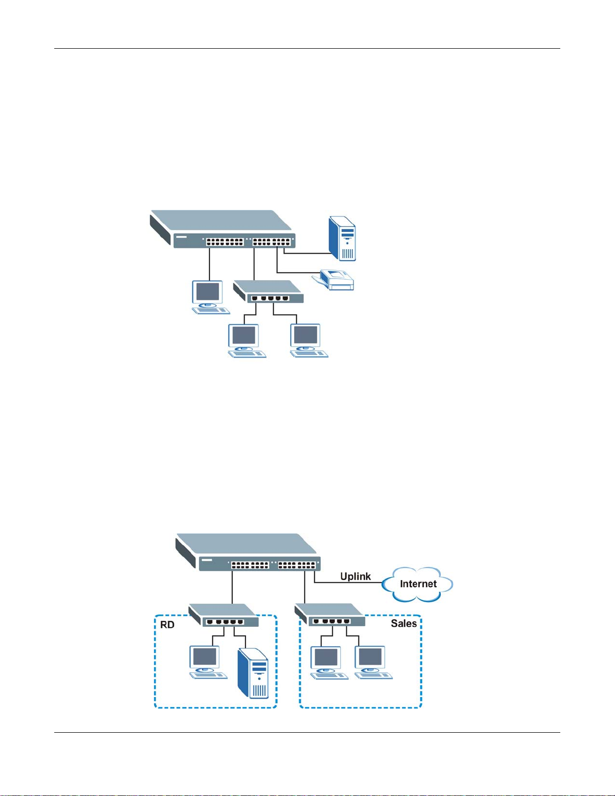
Chapter 1 Getting to Know Your Switch
1.1.1 Backbone Application
The Switch is an ideal solution for small networks where rapid growth can be expected in the near
future. The Switch can be used standalone for a group of heavy traffic users. You can connect
computers and servers directly to the Switch’s port or connect other switches to the Switch.
In this example, all computers can share high-speed applications on the server. To expand the
network, simply add more networking devices such as switches, routers, computers, print servers
etc.
Figure 1 Backbone Application
1.1.2 Bridging Example
In this example, the Switch connects different company departments (RD and Sales) to the
corporate backbone. It can alleviate bandwidth contention and eliminate server and network
bottlenecks. All users that need high bandwidth can connect to high-speed department servers via
the Switch. You can provide a super-fast uplink connection by using a Gigabit Ethernet/mini-GBIC
port on the Switch.
Moreover, the Switch eases supervision and maintenance by allowing network managers to
centralize multiple servers at a single location.
Figure 2 Bridging Application
GS2210/XGS2210 Series User’s Guide
22
Page 23
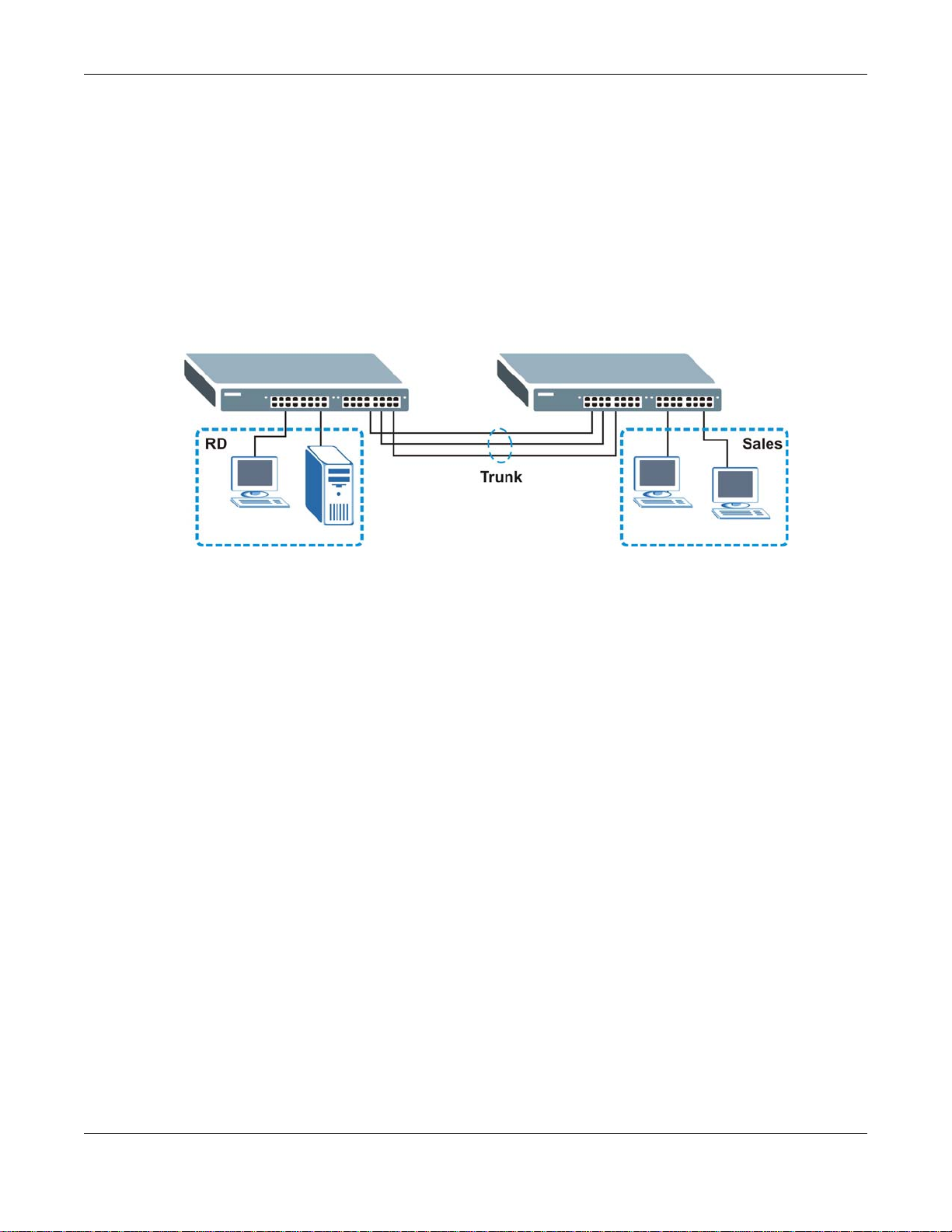
Chapter 1 Getting to Know Your Switch
1.1.3 High Performance Switching Example
The Switch is ideal for connecting two networks that need high bandwidth. In the following
example, use trunking to connect these two networks.
Switching to higher-speed LANs such as ATM (Asynchronous Transmission Mode) is not feasible for
most people due to the expense of replacing all existing Ethernet cables and adapter cards,
restructuring your network and complex maintenance. The Switch can provide the same bandwidth
as ATM at much lower cost while still being able to use existing adapters and switches. Moreover,
the current LAN structure can be retained as all ports can freely communicate with each other.
Figure 3 High Performance Switched Workgroup Application
1.1.4 IEEE 802.1Q VLAN Application Examples
A VLAN (Virtual Local Area Network) allows a physical network to be partitioned into multiple logical
networks. Stations on a logical network belong to one group. A station can belong to more than one
group. With VLAN, a station cannot directly talk to or hear from stations that are not in the same
group(s) unless such traffic first goes through a router.
For more information on VLANs, refer to Chapter 9 on page 101.
1.1.4.1 Tag-based VLAN Example
Ports in the same VLAN group share the same frame broadcast domain thus increase network
performance through reduced broadcast traffic. VLAN groups can be modified at any time by
adding, moving or changing ports without any re-cabling.
Shared resources such as a server can be used by all ports in the same VLAN as the server. In the
following figure only ports that need access to the server need to be part of VLAN 1. Ports can
belong to other VLAN groups too.
GS2210/XGS2210 Series User’s Guide
23
Page 24
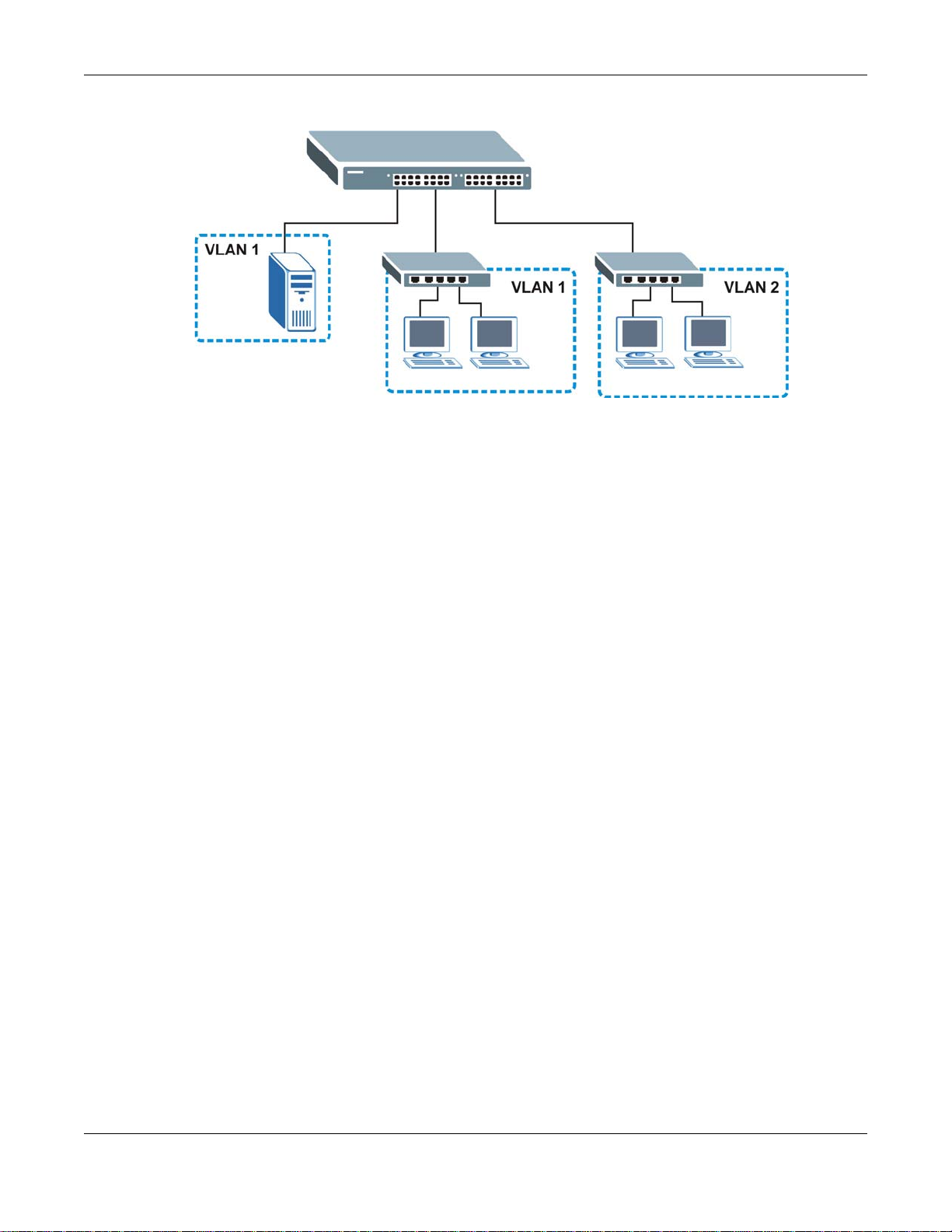
Chapter 1 Getting to Know Your Switch
Figure 4 Shared Server Using VLAN Example
1.2 Ways to Manage the Switch
Use any of the following methods to manage the Switch.
• Web Configurator. This is recommended for everyday management of the Switch using a
(supported) web browser. See Chapter 4 on page 37.
• Command Line Interface. Line commands offer an alternative to the web configurator and in
some cases are necessary to configure advanced features. See the CLI Reference Guide.
• FTP. Use FTP for firmware upgrades and configuration backup/restore. See Section 44.7.1 on
page 379.
• SNMP. The Switch can be monitored by an SNMP manager. See Section 44.5 on page 377.
• Cluster Management. Cluster Management allows you to manage multiple switches through one
switch, called the cluster manager. See Chapter 48 on page 409.
1.3 Good Habits for Managing the Switch
Do the following things regularly to make the Switch more secure and to manage the Switch more
effectively.
• Change the password. Use a password that’s not easy to guess and that consists of different
types of characters, such as numbers and letters.
• Write down the password and put it in a safe place.
• Back up the configuration (and make sure you know how to restore it). Restoring an earlier
working configuration may be useful if the device becomes unstable or even crashes. If you
forget your password, you will have to reset the Switch to its factory default settings. If you
backed up an earlier configuration file, you would not have to totally re-configure the Sw itch. Y ou
could simply restore your last configuration.
GS2210/XGS2210 Series User’s Guide
24
Page 25

CHAPTER 2
Hardware Installation and Connection
2.1 Installation Scenarios
This chapter shows you how to install and connect the Switch.
The Switch can be placed on a desktop or rack-mounted on a standard EIA rack. Use the rubber
feet in a desktop installation and the brackets in a rack-mounted installation.
Note: For proper ventilation, allow at least 4 inches (10 cm) of clearance at the front and
3.4 inches (8 cm) at the back of the Switch. This is especially important for
enclosed rack installations.
2.2 Desktop Installation Procedure
1 Make sure the Switch is clean and dry.
2 Set the Switch on a smooth, level surface strong enough to support the weight of the Switch and
the connected cables. Make sure there is a power outlet nearby.
3 Make sure there is enough clearance around the Switch to allow air circulation and the attachment
of cables and the power cord.
2.3 Mounting the Switch on a Rack
The Switch can be mounted on an EIA standard size, 19-inch rack or in a wiring closet with other
equipment. Follow the steps below to mount your Switch on a standard EIA rack using a rackmounting kit.
2.3.1 Rack-mounted Installation Requirements
• Two mounting brackets.
• Eight M3 flat head screws and a #2 Philips screwdriver.
• Four M5 flat head screws and a #2 Philips screwdriver.
Failure to use the proper screws may damage the unit.
2.3.1.1 Precautions
• Make sure the rack will safely support the combined weight of all the equipment it contains.
GS2210/XGS2210 Series User’s Guide
25
Page 26
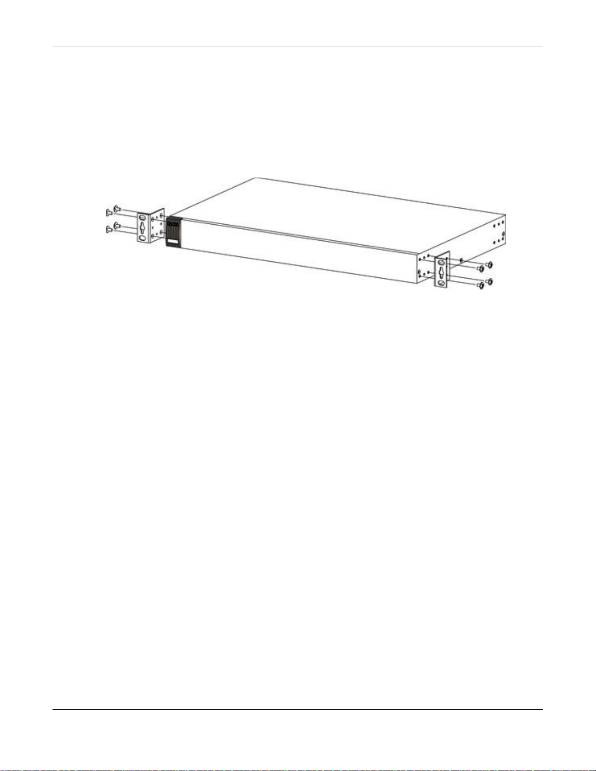
Chapter 2 Hardware Installation and Connection
• Make sure the position of the Switch does not make the rack unstable or top-heavy. Take all
necessary precautions to anchor the rack securely before installing the unit.
2.3.2 Attaching the Mounting Brackets to the Switch
1 Position a mounting bracket on one side of the Switch, lining up the four screw holes on the br acket
with the screw holes on the side of the Switch.
Figure 5 Attaching the Mounting Brackets
2 Using a #2 Philips screwdriver, install the M3 flat head screws through the mounting bracket holes
into the Switch.
3 Repeat steps 1 and 2 to install the second mounting bracket on the other side of the Switch.
4 You may now mount the Switch on a rack. Proceed to the next section.
2.3.3 Mounting the Switch on a Rack
1 Position a mounting bracket (that is already attached to the Switch) on one side of the rack, lining
up the two screw holes on the bracket with the screw holes on the side of the rack.
GS2210/XGS2210 Series User’s Guide
26
Page 27
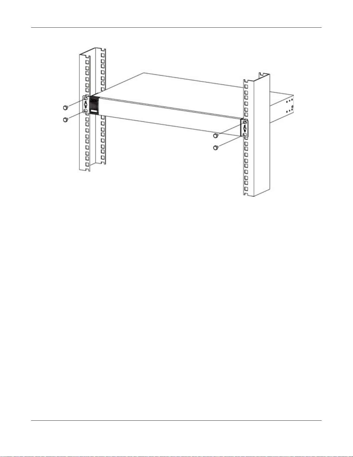
Chapter 2 Hardware Installation and Connection
Figure 6 Mounting the Switch on a Rack
2 Using a #2 Philips screwdriver, install the M5 flat head screws through the mounting bracket holes
into the rack.
3 Repeat steps 1 and 2 to attach the second mounting bracket on the other side of the rack.
2.4 W all Mounting (for GS2210-8 only)
Do the following to attach your Switch to a wall.
Insecure mounting may damage the device or cause injury . ZyXEL is not
responsible for damages incurred by insecure wall-mounting.
1 Screw the two screws provided with your Switch into the wall 135 mm apart (see Figure 7 on page
28). See Figure 8 on page 28 for the size of screws to use.
Do not screw the screws all the way in to the wall; leave a small gap between the head of the screw
and the wall.
The gap must be big enough for the screw heads to slide into the screw slots and the connection
cables to run down the back of the Switch.
Note: Make sure the screws are securely fixed to the wall and strong enough to hold the
weight of the Switch with the connection cables.
2 Align the holes on the back of the Switch with the screws on the wall. Hang the Switch on the
screws.
GS2210/XGS2210 Series User’s Guide
27
Page 28
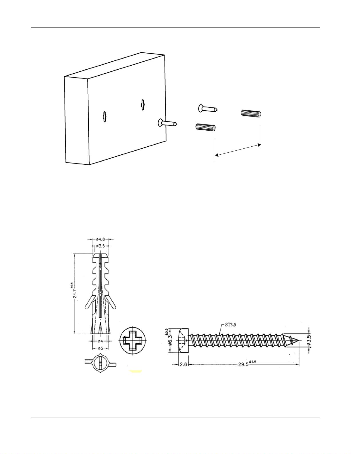
Chapter 2 Hardware Installation and Connection
1
3
5
m
m
Figure 7 Wall-mounting Example
The Switch should be wall-mounted horizontally. The Switch's side
panels with ventilation slots should not be facing up or down as this
position is less safe.
The following are dimensions of a self-tapping screw and masonry plug used for wall mounting. All
measurements are in millimeters (mm).
Figure 8 Masonry Plug and 3.5 mm Self-Tapping Screw
GS2210/XGS2210 Series User’s Guide
28
Page 29

This chapter describes the front panel and rear panel of the Switch and shows you how to make the
hardware connections.
3.1 Front Panel
The following figures show the front panels of the Switch.
Figure 9 Front Panel: GS2210-8
Figure 10 Front Panel: GS2210-8HP
CHAPTER 3
Hardware Panels
Figure 11 Front Panel: GS2210-24
Figure 12 Front Panel: GS2210-24HP
Figure 13 Front Panel: GS2210-48
Figure 14 Front Panel: GS2210-48HP
Figure 15 Front Panel: XGS2210-28
GS2210/XGS2210 Series User’s Guide
29
Page 30
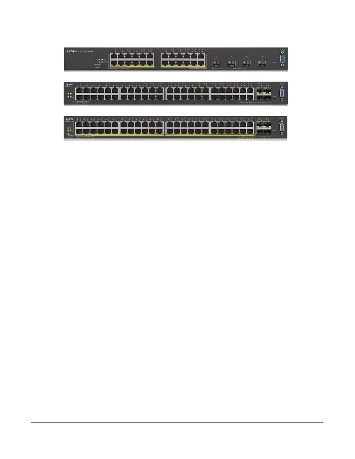
Figure 16 Front Panel: XGS2210-28HP
Figure 17 Front Panel: XGS2210-52
Figure 18 Front Panel: XGS2210-52HP
3.1.1 Gigabit Ethernet Ports
The Switch has 1000Base- T auto-negotiating, auto-crossover Ethernet ports. In 10/100/1000 Mbps
Gigabit, the speed can be 10 Mbps, 100 Mbps or 1000 Mbps and the duplex mode can be half
duplex or full duplex.
Chapter 3 Hardware Panels
An auto-negotiating port can detect and adjust to the optimum Ethernet speed (10/100/1000
Mbps) and duplex mode (full duplex or half duplex) of the connected device.
An auto-crossover (auto-MDI/MDI-X) port automatically works with a str aight -through or crossov er
Ethernet cable.
Four 1000Base-T Ethernet ports are paired with a mini-GBIC slot to create a dual personality
interface. The Switch uses up to one connection for each mini-GBIC and 1000Base-T Ethernet pair.
The mini-GBIC slots have priority over the Gigabit ports. This means that if a mini-GBIC slot and
the corresponding GbE port are connected at the same time, the GbE port will be disabled.
Note: The dual personality ports change to fiber mode directly when inserting the fiber
module.
When auto-negotiation is turned on, an Ethernet port negotiates with the peer automatically to
determine the connection speed and d upl ex mod e. If the peer Ethernet port does not support autonegotiation or turns off this feature, the Switch determines the connection speed by detecting the
signal on the cable and using half duplex mode. When the Switch’s auto-negotiation is turned off,
an Ethernet port uses the pre-configured speed and duplex mode when making a connection, thus
requiring you to make sure that the settings of the peer Ethernet port are the same in order to
connect.
3.1.1.1 Default Ethernet Negotiation Settings
The factory default negotiation settings for the Gigabit ports on the Switch are:
• Speed: Auto
•Duplex: Auto
• Flow control: Off
• Link Aggregation: Disabled
GS2210/XGS2210 Series User’s Guide
30
Page 31

3.1.1.2 Auto-crossover
All ports are auto-crossover, that is auto-MDIX ports (Media Dependent Interface Crossover), so
you may use either a straight-through Ethernet cable or crossover Ethernet cable for all Gigabit port
connections. Auto-crossover ports automatically sense whether they need to function as crossover
or straight ports, so crossover cables can connect both computers and switches/hubs.
3.1.2 Mini-GBIC Slots
These are slots for mini-GBIC (Gigabit Interface Converter) transceivers. A transceiver is a single
unit that houses a transmitter and a receiver. The Switch does not come with transceivers. You
must use transceivers that comply with the Small Form-factor Pluggable (SFP) Transceiver
MultiSource Agreement (MSA). See the SFF committee’s INF-8074i specification Rev 1.0 for details.
You can change transceivers while the Switch is operating. You can use different transceivers to
connect to Ethernet switches with different types of fiber-optic or even copper cable connectors.
To avoid possible eye injury, do not look into an operating fiber-optic
module’s connectors.
Chapter 3 Hardware Panels
• Type: SFP connection interface
• Connection speed: 1 Gigabit per second (Gbps)
3.1.2.1 Transceiver Installation
Use the following steps to install a mini-GBIC transceiver (SFP module).
1 Insert the transceiver into the slot with the exposed section of PCB board facing down.
2 Press the transceiver firmly until it clicks into place.
3 The Switch automatically detects the installed transceiver. Check the LEDs to verify that it is
functioning properly.
4 Close the transceiver’s latch (latch styles vary).
5 Connect the fiber optic cables to the transceiver.
Figure 19 Transceiver Installation Example
GS2210/XGS2210 Series User’s Guide
31
Page 32
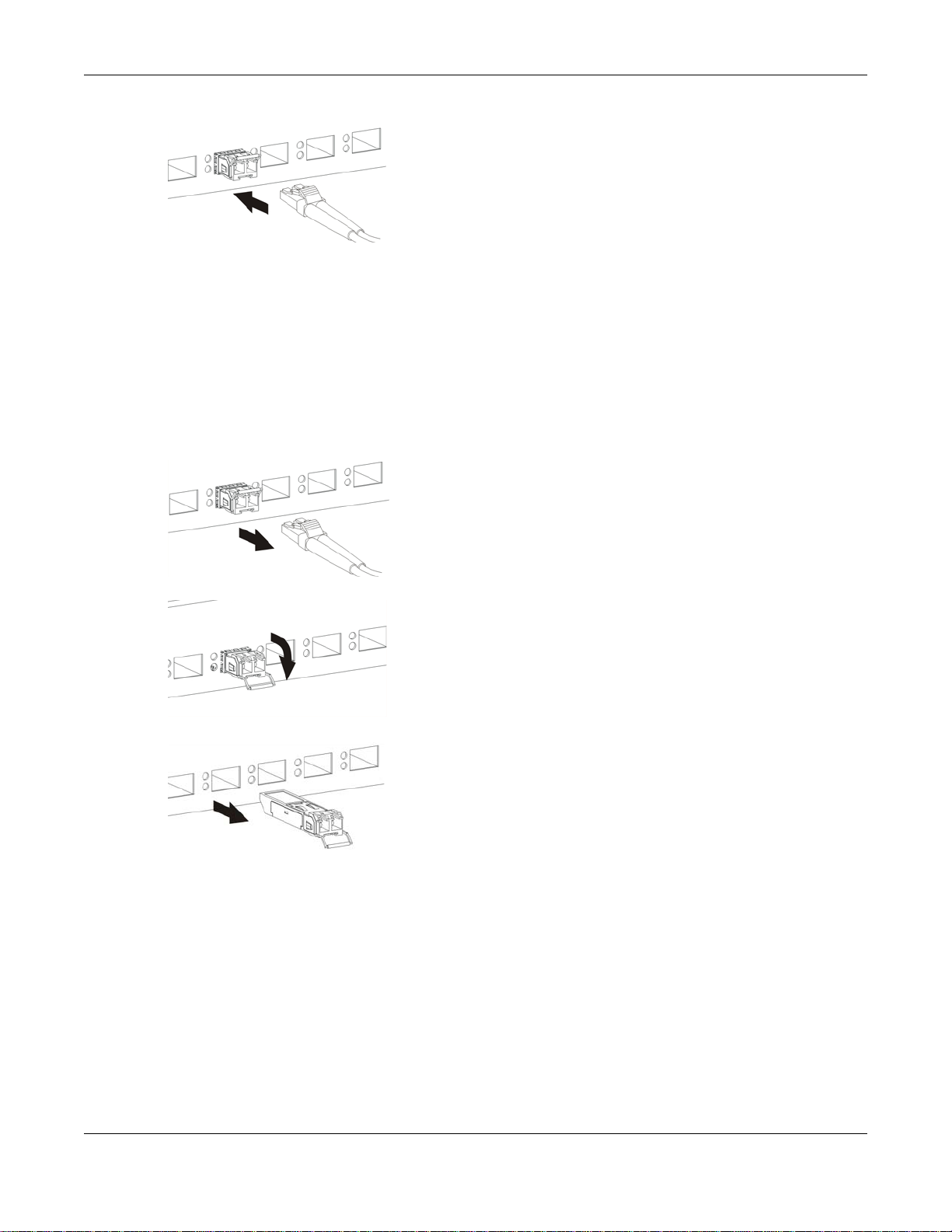
Figure 20 Connecting the Fiber Optic Cables
3.1.2.2 Transceiver Removal
Use the following steps to remove a mini-GBIC transceiver (SFP module).
1 Remove the fiber optic cables from the transceiver.
2 Open the transceiver’s latch (latch styles vary).
3 Pull the transceiver out of the slot.
Figure 21 Removing the Fiber Optic Cables
Chapter 3 Hardware Panels
Figure 22 Opening the Transceiver’s Latch Example
Figure 23 Transceiver Removal Example
3.1.3 LED Mode (only available for GS2210-48HP)
After you push this button (see Section Figure 14 on page 29) to active PoE on the Switch, view the
LEDs to ensure proper functioning of the Switch and as an aid in troubleshooting (see Section 3.3
on page 34).
3.2 Rear Panel
The following figures show the rear panels of the Switch.
GS2210/XGS2210 Series User’s Guide
32
Page 33
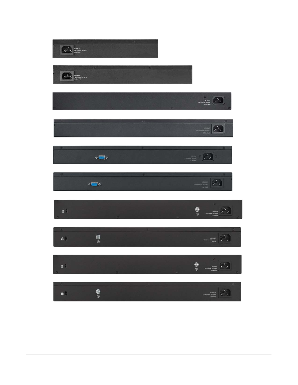
Chapter 3 Hardware Panels
Figure 24 Rear Panel: GS2210-8
Figure 25 Rear Panel: GS2210-8HP
Figure 26 Rear Panel: GS2210-24
Figure 27 Rear Panel: GS2210-24HP
Figure 28 Rear Panel: GS2210-48
Figure 29 Rear Panel: GS2210-48HP
Figure 30 Rear Panel: XGS2210-28
Figure 31 Rear Panel: XGS2210-28HP
Figure 32 Rear Panel: XGS2210-52
Figure 33 Rear Panel: XGS2210-52HP
3.2.1 Console Port
For local management, you can use a computer with terminal emulation software configured to the
following parameters:
• VT100
GS2210/XGS2210 Series User’s Guide
33
Page 34

• Terminal emulation
• 9600 bps
• No parity, 8 data bits, 1 stop bit
• No flow control
Connect the male 9-pin end of the console cable to the console port of the Switch. Connect the
female end to a serial port (COM1, COM2 or other COM port) of your computer.
3.2.2 Power Connector
Note: Make sure you are using the correct power source as shown on the panel.
T o connect power to the Switch, insert the female end of the power cord to the AC power receptacle
on the rear panel. Connect the other end of the supplied power cord to a power outlet. Make sure
that no objects obstruct the airflow of the fans (located on the side of the unit).
See Chapter 57 on page 432 for information on the Switch’s power supply requirements.
Chapter 3 Hardware Panels
3.3 LEDs
After you connect the power to the Switch, view the LEDs to ensure proper functioning of the
Switch and as an aid in troubleshooting.
Table 4 LED Descriptions
LED COLOR STATUS DESCRIPTION
PoE
(GS2210-48HP
only)
PWR Green On The system is turned on.
SYS Green On The system is on and functioning properly.
ALM Red On A hardware failure is detected.
FAN Green On The fan is functioning properly.
LOCAT OR Blue Blinking Shows the actual location of the Switch between sev eral devi ces in a ra ck.
PoE MAX
(XGS221028HP/52HP)
Green On Each Ethernet port’s LED is changed to act as a P oE LED by using the LED
Off Each Ethernet port’s LED is changed back to act as a LNK/ACT LED by
Off The system is off or has failed.
Blinking The system is rebooting and performing self-diagnostic tests.
Off The power is off or the system is not ready/malfunctioning.
Red
(XGS2210-28/
28HP/52/52HP)
Amber On The fan is malfunctioning.
Green On PoE power usage is over 80 percent of the power supplied budget, but
Amber On PoE power usage is more than 95 percent of the power supplied budget.
On A hardware failure is detected.
Off The system is functioning normally.
Off The system is functioning normally.
Off PoE power usage is below 80 percent of the power supplied budget.
MODE button on the front panel.
releasing the LED MODE button on the front panel.
below 95 percent of the power supplied budget.
GS2210/XGS2210 Series User’s Guide
34
Page 35

Chapter 3 Hardware Panels
Table 4 LED Descriptions (continued)
LED COLOR STATUS DESCRIPTION
Ethernet Ports and PoE
LNK/ACT
1-8 (GS2210-8/
8HP)
1-24 (GS221024/24HP,
XGS2210-28/
28HP) and 1-48
(GS2210-48/
48HP,
XGS2210-52/
52HP)
PoE
(GS2210-8HP,
GS2210-24HP,
GS2210- 48HP,
XGS2210-28HP
and XGS221052HPonly)
Mini-GBIC Slots
SFP
9-10 (GS22108/8HP0
25-28
(GS2210-24/
24HP)
45-50
(GS2210-48/
48HP)
SFP+
25-28
(XGS2210-28/
28HP)
49-52
(XGS2210-52/
52HP)
Green On The link to a 10 Mbps or a 1000 Mbps Ethernet network is up.
Blinking The system is transmitting/receiving to/from a 10 Mbps or a 1000 Mbps
Ethernet network.
Amber On The link to a 100 Mbps Ethernet network is up.
Blinking The system is transmitting/receiving to/from a 100 Mbps Ethernet
network.
Off The link to an Ethernet network is down.
Green On Power supplied to all PoE Ethernet ports meets the IEEE 802.3at
standard.
Amber On Power supplied to all PoE Ethernet ports meets the IEEE 802.3af standard.
Off There is no power supplied.
Green On The uplink port is linking at 1000 Mbps.
Blinking The system activity is transmitting/receiving data 1000 Mbps.
Amber On The uplink port is linking at 100 Mbps.
Blinking The system activity is transmitting/receiving data 100 Mbps.
Off There is no link or port, the uplink port is shut down.
Green On The uplink port is linking at 1000 Mbps.
Blinking The system activity is transmitting/receiving data 1000 Mbps.
Blue On The uplink port is linking at 10 Gbps.
Blinking The system activity is transmitting/receiving data 10 Gbps.
Off There is no link or port, the uplink port is shut down.
GS2210/XGS2210 Series User’s Guide
35
Page 36

PART II
Technical Reference
36
Page 37

4.1 Overview
This section introduces the configuration and functions of the web configurator.
The web configurator is an HTML-based management interface that allows easy Switch setup and
management via Internet browser. Use Internet Explorer 9.0 and later versions, Mozilla Firefox 21
and later versions, Safari 6.0 and later versions or Google Chrome 26.0 and later versions. The
recommended screen resolution is 1024 by 768 pixels.
In order to use the web configurator you need to allow:
• Web browser pop-up windows from your device. Web pop-up blocking is enabled by default in
Windows XP SP (Service Pack) 2.
• JavaScript (enabled by default).
• Java permissions (enabled by default).
CHAPTER 4
The Web Configurator
4.2 System Login
1 Start your web browser.
2 T ype “http://” and the IP address of the Switch (for example, the default management IP address is
192.168.1.1) in the Location or Address field. Press [ENTER]. Your computer must be in the same
subnet in order to access this website address.
3 The login screen appears. The default username is admin and associated default password is
1234. The date and time display as shown if you have not configured a time server nor manually
entered a time and date in the General Setup screen.
GS2210/XGS2210 Series User’s Guide
37
Page 38

Chapter 4 The Web Configurator
A
B
G
C
D
E
F
Figure 34 Web Configurator: Login
4 Click OK to view the first web configurator screen.
4.3 The Status Screen
The Status screen is the first screen that displays when you access the web configurator.
This guide uses the XGS2210-52HP screens as an example. The screens may very slightly for
different models.
The following figure shows the navigating components of a web configurator screen.
Figure 35 Web Configurator Home Screen for PoE model(s) (Status)
A - Click the menu items to open submenu links, and then click on a submenu link to open the
screen in the main window.
GS2210/XGS2210 Series User’s Guide
38
Page 39

Chapter 4 The Web Configurator
B, C, D, E, F - These are quick links which allow you to perform certain tasks no matter which
screen you are currently working in.
B - Click this link to update the information in the screen you are viewing currently.
C - Click this link to save your configuration into the Switch’s nonvolatile memory. Nonvolatile
memory is the configuration of your Switch that stays the same even if the Sw itch’s power is turned
off.
D - Click this link to go to the status page of the Switch.
E - Click this link to log out of the web configurator.
F - Click this link to display web help pages. The help pages provide descriptions for all of the
configuration screens.
G - Click this link to go to the ZON Neighbor Management screen where you can see and manage
neighbor devices learned by the Switch.
In the navigation panel, click a main link to reveal a list of submenu links.
Table 5 Navigation Panel Sub-links Overview
BASIC SETTING ADVANCED APPLICATION IP APPLICATION MANAGEMENT
GS2210/XGS2210 Series User’s Guide
39
Page 40

Chapter 4 The Web Configurator
The following table describes the links in the navigation panel.
Table 6 Navigation Panel Links
LINK DESCRIPTION
Basic Settings
System Info This link takes you to a screen that displays general system information.
General Setup This link takes you to a screen where you can configure general identification information
Switch Setup This link takes you to a screen where you can set up global Switch parameters such as
IP Setup This link takes you to a screen where you can configure the IP address and subnet mask
Port Setup This link takes you to a screen where you can configure settings for individual Switch ports.
PoE Setup For PoE model(s).
Interface Setup This link takes you to a screen where you can configure settings for individual interface
IPv6 This link takes you to a screen where you can view IPv6 status and configure IPv6 settings.
DNS This link takes you to a screen where you can configure DNS (domain name server) IP
Advanced Application
VLAN This link takes you to screens where you can configure port-based or 802.1Q VLAN
Static MAC
Forwarding
Static Multicast
Forwarding
Filtering This link takes you to a screen to set up filtering rules.
Spanning Tree
Protocol
Bandwidth
Control
Broadcast Storm
Control
Mirroring This link takes you to screens where you can copy tr affic from one port or ports to another
Link Aggregation This link takes you to screens where you can logically aggregate physical links to form one
Port
Authentication
Port Security This link takes you to screens where you can activate MAC address learning and set the
Time Range This link takes you to a screen where you can define different schedules.
Classifier This link takes you to screens where you can configure the Switch to group packets based
Policy Rule This link takes you to a screen where you can configure the Switch to perform special
about the Switch.
VLAN type, GARP and priority queues.
(necessary for Switch management) and set up to 64 IP routing domains.
This link takes you to a screen where you can set priorities, PoE power-up settings and
schedule so that the Switch is able to reserve and allocate power to certain PDs.
type and ID.
addresses.
(depending on what you configured in the Switch Setup menu). You can also configure a
protocol based VLAN or a subnet based VLAN in these screens.
This link takes you to a screen where you can configure static MAC addresses for a port.
These static MAC addresses do not age out.
This link takes you to a screen where you can configure static multicast MAC addresses for
port(s). These static multicast MAC addresses do not age out.
This link takes you to screens where you can configure the RSTP/MRSTP/MSTP to prevent
network loops.
This link takes you to a screen where you can configure bandwidth limits on the Switch.
This link takes you to a screen to set up broadcast filters.
port in order that you can examine the traffic from the first port without interference.
logical, higher-bandwidth link.
This link takes you to a screen where you can configure IEEE 802.1x port authentication for
clients communicating via the Switch.
maximum number of MAC addresses to learn on a port.
on the specified criteria.
treatment on the grouped packets.
GS2210/XGS2210 Series User’s Guide
40
Page 41

Chapter 4 The Web Configurator
Table 6 Navigation Panel Links (continued)
LINK DESCRIPTION
Queuing Method This link takes you to a screen where you can configure queuing with associated queue
weights for each port.
Multicast This link takes you to screens where you can configure various multicast features, IGMP
snooping, MLD snooping-proxy and create multicast VLANs.
AAA This link takes you to a screen where you can configure authentication, authorization and
IP Source Guard This link takes you to screens where you can configure filtering of unauthorized DHCP and
Loop Guard This link takes you to a screen where you can configure protection against network loops
Layer 2 Protocol
Tunneling
sFlow This link takes you to screens where you can configure sFlow settings on the Switch.
PPPoE This link takes you to screens where you can configure intermediate agent settings in port,
Errdisable This link takes you to screens where you can view errdisable status and configure
MAC Pinning This link takes you t o a sc ree n w he re you can set specific ports t o have priority over o th er
Private VLAN This link takes you to a screen where you can configure private VLANs.
Green Ethernet This link takes you to a screen where you can configure green Ethernet settings in EEE,
LLDP This link takes you to screens where you can configure LLDP settings.
Anti-Arpscan This link takes you to screens where you can enable anti-arpscan on the Switch and ports,
BPDU Guard This link takes you to screens where you can enable BPDU guard on the Switch and ports,
OAM This link takes you to screens where you can enable Ethernet OAM on the Switch, view the
ZULD This link takes you to screens where you can enable ZULD on a port and configure related
IP Application
Static Routing This link takes you to a screen where you can configure IPv4 static routes. A static route
DiffServ This link takes you to screens where you can enable DiffServ , configure marki ng rules and
DHCP This link takes you to screens where you can configure the DHCP settings.
ARP Setup This link takes you to screens where you can configure the ARP learning settings for each
Management
Maintenance This link takes you to screens where you can perform firmware and configuration file
Access Control This link takes you to screens where you can change the system login password and
accounting services via external servers. The external servers can be either RADIUS
(Remote Authenticatio n Dial-In User Service) or TACACS+ (Terminal Access Controller
Access-Control System Plus).
ARP packets in your network.
that occur on the edge of your network.
This link takes you to a screen where you can configure L2PT (Layer 2 Protocol Tunneling)
settings on the Switch.
VLAN, and PPPoE.
errdisable settings in CPU protection, errdisable detect, and errdisable recovery.
ports in MAC address learning.
auto power down, and short reach for each port.
and view the port state. You can also create trusted hosts, view blocked hosts and unblock
them.
and view the port state
configuration of ports on which Ethernet OAM is enabled and perform remote-loopback
tests.
settigns.
defines how the Switch should forward traffic by configuring the TCP/IP parameters
manually.
set DSCP-to-IEEE802.1p mappings.
port.
maintenance as well as reboot the system.
configure SNMP and remote management.
GS2210/XGS2210 Series User’s Guide
41
Page 42
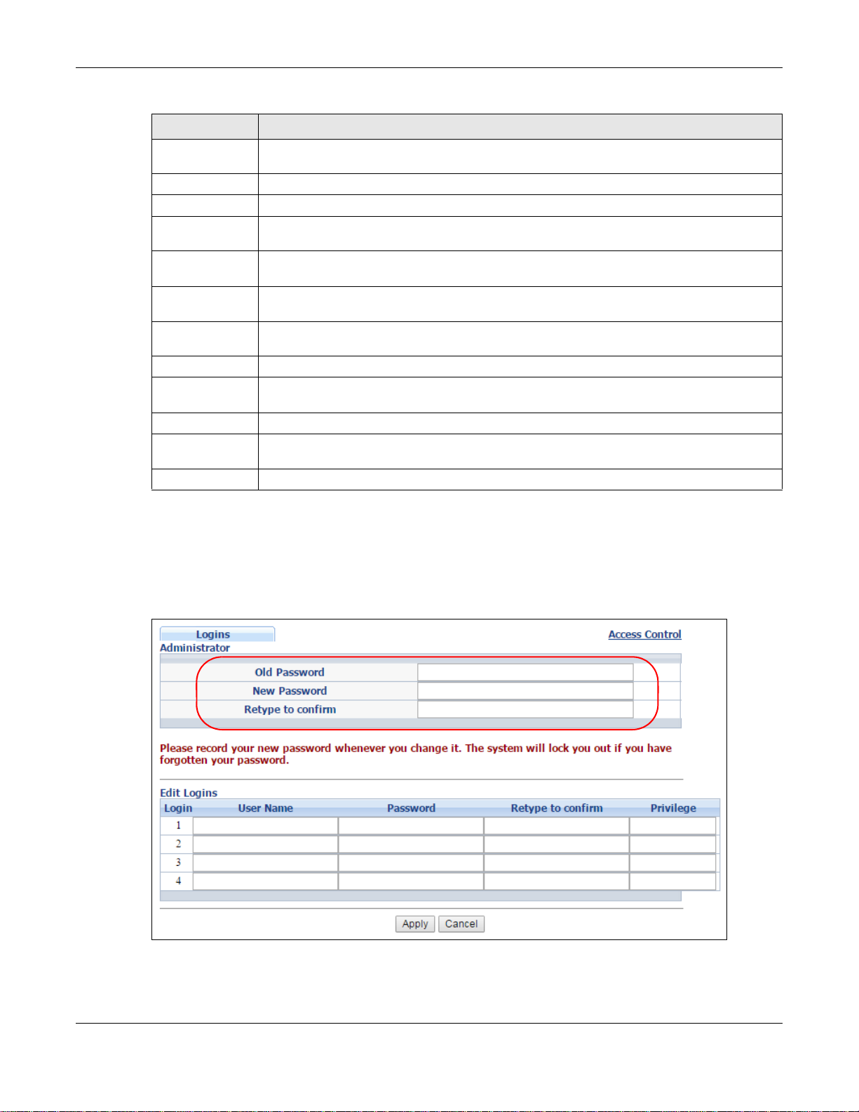
Chapter 4 The Web Configurator
Table 6 Navigation Panel Links (continued)
LINK DESCRIPTION
Diagnostic This link takes you to a screen where you can ping IP addresses, run traceroute, test
port(s) and show the Switch’s location.
System Log This link takes you to a screen where you can view system logs.
Syslog Setup This link takes you to a screen where you can setup system logs and a system log server.
Cluster
Management
MAC Table This link takes you to a screen where you can view the MAC addresses (and types) of
IP Table This link takes you to a screen where you can view the IP addresses and VLAN ID of a
ARP Table This link takes you to a screen where you can view the MAC addresses – IP address
Routing Table This link takes you to a screen where you can view the routing table.
Path MTU Table This link takes you to a screen where you can view the path MTU aging time, index,
Configure Clone This link takes you to a screen where you can copy attributes of one port to other ports.
IPv6 Neighbor
Table
Port Status This link takes you to a screen where you can view the port statistics.
This link takes y ou to screens wh ere you can configure clus tering management and view its
status.
devices attached to what ports and VLAN IDs.
device attached to a port.You can also view what kind of device it is.
resolution table.
destination address, MTU, and expire settings.
This link takes you to a screen where you can view the IPv6 neighbor table which includes
index, interface, neighbor address, MAC address, status and type.
4.3.1 Change Your Password
After you log in for the first time, it is recommended you change the default administrator
password. Click Management > Access Control > Logins to display the next screen.
Figure 36 Change Administrator Login Password
GS2210/XGS2210 Series User’s Guide
42
Page 43

Chapter 4 The Web Configurator
4.4 Saving Your Configuration
When you are done modifying the settings in a screen, click Apply to save your changes back to
the run-time memory. Settings in the run-time memory are lost when the S w it ch’s power is turned
off.
Click the Save link in the upper right hand corner of the web configurator to save your
configuration to nonvolatile memory. Nonvolatile memory refers to the Switch’s storage that
remains even if the Switch’s power is turned off.
Note: Use the Save link when you are done with a configuration session.
4.5 Switch Lockout
You could block yourself (and all others) from managing the Switch if you do one of the following:
1 Delete the management VLAN (default is VLAN 1).
2 Delete all port-based VLANs with the CPU port as a member. The “CPU port” is the management
port of the Switch.
3 Filter all traffic to the CPU port.
4 Disable all ports.
5 Misconfigure the text configuration file.
6 Forget the password and/or IP address.
7 Prevent all services from accessing the Switch.
8 Change a service port number but forget it.
Note: Be careful not to lock yourself and others out of the Switch.
4.6 Resetting the Switch
If you lock yourself (and others) from the Switch or forget the administrator password, you will
need to reload the factory-default configuration file or reset the S w itch back to the factory defaults.
4.6.1 Reload the Configuration File
Uploading the factory-default configuration file replaces the current configuration file with the
factory-default configuration file. This means that you will lose all previous configurations and the
speed of the console port will be reset to the default of 9600 bps with 8 data bits, no parity, one
stop bit and flow control set to none. The password will also be reset to “1234” and the IP address
to 192.168.1.1.
GS2210/XGS2210 Series User’s Guide
43
Page 44

Chapter 4 The Web Configurator
To upload the configuration file, do the following:
1 Connect to the console port using a computer with terminal emulation software.
2 Disconnect and reconnect the Switch’s power to begin a session. When you reconnect the Switch’s
power, you will see the initial screen.
3 When you see the message “Press any key to enter Debug Mode within 3 seconds...” press
any key to enter debug mode.
4 Type atlc after the “Enter Debug Mode” message.
5 Wait for the “ Starting XMODEM upload” message before activating XMODEM upload on your
terminal.
6 After a configuration file upload, type atgo to restart the Switch.
The Switch is now reinitialized with a default configuration file including the default password of
“1234”.
4.7 Logging Out of the Web Configurator
Click Logout in a screen to exit the web configurator. You have to log in with your password again
after you log out. This is recommended after you finish a management session for security reasons.
Figure 37 Web Configurator: Logout Screen
4.8 Help
The web configurator’s online help has descriptions of individual screens and some supplementary
information.
Click the Help link from a web configurator screen to view an online help description of that screen.
GS2210/XGS2210 Series User’s Guide
44
Page 45
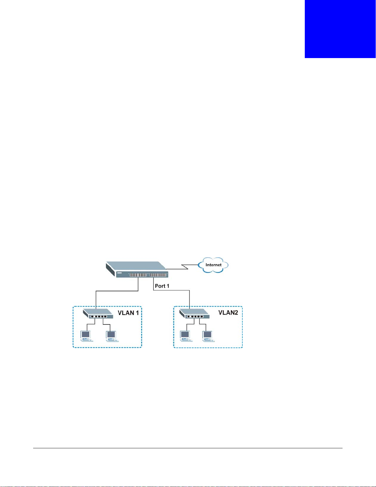
5.1 Overview
This chapter shows how to set up the Switch for an example network.
The following lists the configuration steps for the initial setup:
• Create a VLAN
• Set port VLAN ID
• Configure the Switch IP management address
5.1.1 Creating a VLAN
VLANs confine broadcast frames to the VLAN group in which the port(s) belongs. You can do this
with port-based VLAN or tagged static VLAN with fixed port members.
CHAPTER 5
Initial Setup Example
In this example, you want to configure port 1 as a member of VLAN 2.
Figure 38 Initial Setup Network Example: VLAN
1 Click Advanced Application > VLAN > VLAN Configuration in the na vigation panel and click the
Static VLAN Setup link.
GS2210/XGS2210 Series User’s Guide
45
Page 46

Chapter 5 Initial Setup Example
2 In the Static VLAN screen, select ACTIVE, enter
a descriptive name in the Name field and enter 2
in the VLAN Group ID field for the VLAN2
network.
Note: The VLAN Group ID field in this screen and the VID field in the IP Setup screen
refer to the same VLAN ID.
3 Since the VLAN2 network is connected to port 1 on the Switch, select Fixed to configure port 1 to
be a permanent member of the VLAN only.
4 To ensure that VLAN-unaware devices (such as computers and hubs) can receive frames properly,
clear the TX Tagging check box to set the Switch to remove VLAN tags before sending.
5 Click Add to save the settings to the run-time memory. Settings in the run-time memory are lost
when the Switch’s power is turned off.
5.1.2 Setting Port VID
Use PVID to add a tag to incoming untagged frames received on that port so that the frames are
forwarded to the VLAN group that the tag defines.
In the example network, configure 2 as the port VID on port 1 so that any untagged frames
received on that port get sent to VLAN 2.
GS2210/XGS2210 Series User’s Guide
46
Page 47

Chapter 5 Initial Setup Example
Figure 39 Initial Setup Network Example: Port VID
1 Click Advanced Applications > VLAN >
VLAN Configuration in the navigation
panel. Then click the VLAN Port Setup link.
2 Enter 2 in the PVID field for port 2 and click
Apply to save your changes back to the run-
time memory. Settings in the run-time
memory are lost when the Switch’s power is
turned off.
5.2 Configuring Switch Management IP Address
The default management IP address of the Switch is 192.168.1.1. You can configure another IP
address in a different subnet for management purposes. The following figure shows an example.
Figure 40 Initial Setup Example: Management IP Address
GS2210/XGS2210 Series User’s Guide
47
Page 48
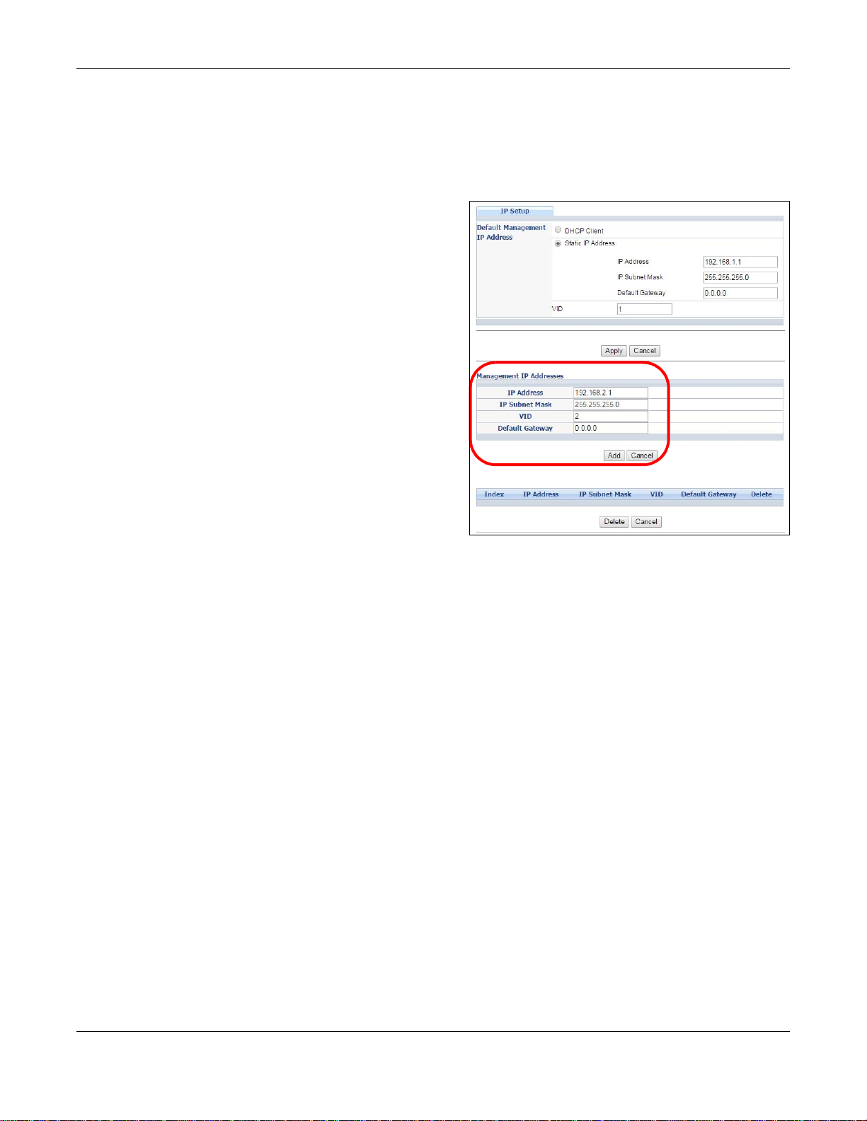
Chapter 5 Initial Setup Example
1 Connect your computer to any Ethernet port on the Switch. Make sure your computer is in the same
subnet as the Switch.
2 Open your web browser and enter 192.168.1.1 (the default IP address) in the address bar to access
the web configurator. See Section 4.2 on page 37 for more information.
3 Click Basic Setting > IP Setup in the
navigation panel.
4 Configure the related fields in the IP Setup
screen.
5 For the VLAN2 network, enter 192.168 .2.1 as
the IP address and 255.255.255.0 as the
subnet mask.
6 In the VID field, enter the ID of the VLAN group
to which you want this management IP address
to belong. This is the same as the VLAN ID you
configure in the Static VLAN screen.
7 Click Add to save your changes back to the run-
time memory . Settings in the run-time memory
are lost when the Switch’s power is turned off.
GS2210/XGS2210 Series User’s Guide
48
Page 49
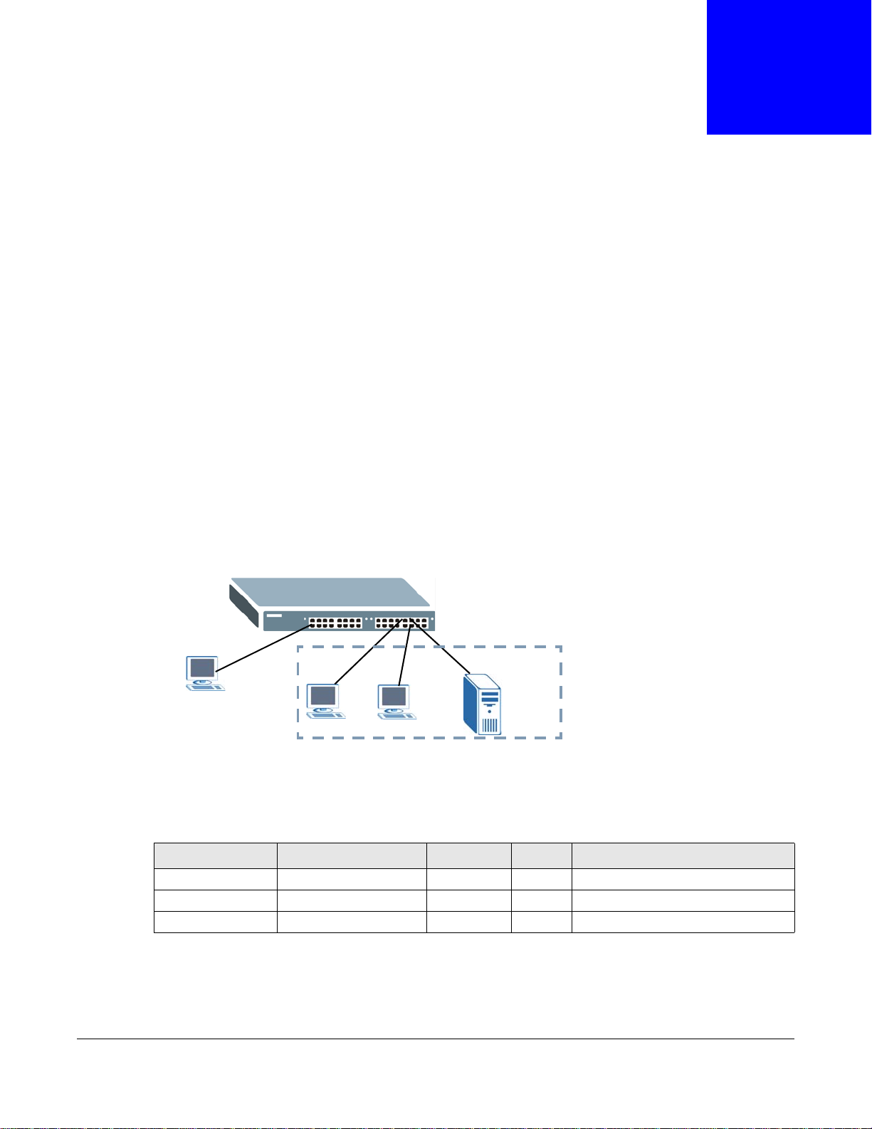
CHAPTER 6
V
A
B
M
C
Tutorials
6.1 Overview
This chapter provides some examples of using the web configurator to set up and use the Switch.
The tutorials include:
• How to Use DHCPv4 Snooping on the Switch
• How to Use DHCPv4 Relay on the Switch
6.2 How to Use DHCPv4 Snooping on the Switch
You only want DHCP server A connected to port 5 to assign IP addresses to all devices in VLAN
network (V). Create a VLAN containing ports 5, 6 and 7. Connect a computer M to the Switch for
management.
Figure 41 Tutorial: DHCP Snooping Tutorial Overview
Note: For related information about DHCP snoopi ng, see Section 26.1 on page 232.
The settings in this tutorial are as the following.
Table 7 Tutorial: Settings in this Tutorial
HOST PORT CONNECTED VLAN PVID DHCP SNOOPING PORT TRUSTED
DHCP Server (A) 5 1 and 100 100 Yes
DHCP Client (B) 6 1 and 100 100 No
DHCP Client (C) 7 1 and 100 100 No
1 Access the Switch through http://192.168.1.1 by default. Log into the Switch by entering the
username (default: admin) and password (default: 1234).
49
GS2210/XGS2210 Series User’s Guide
Page 50
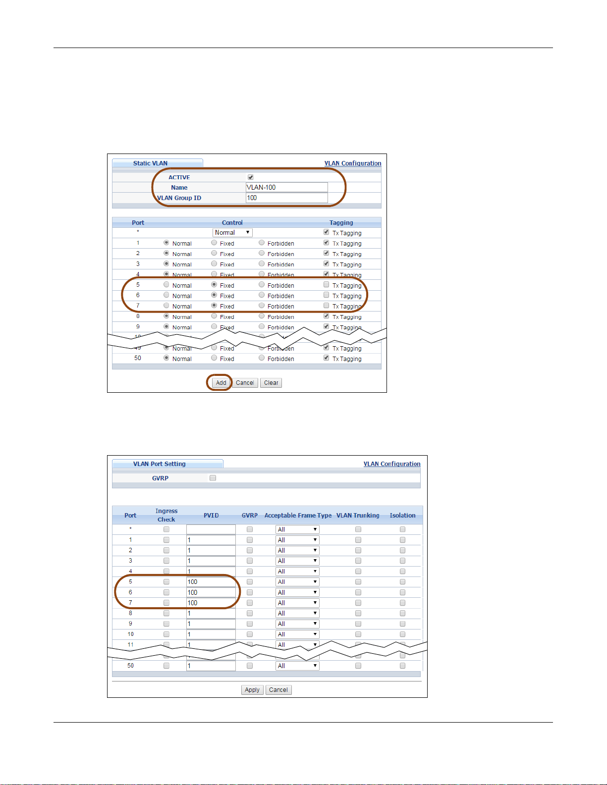
Chapter 6 Tutorials
2 Go to Advanced Application > VLAN > VLAN Configuration > Static VLAN Setup, and create
a VLAN with ID of 100. Add ports 5, 6 and 7 in the VLAN by selecting Fixed in the Control field as
shown.
Deselect Tx Tagging because you don’t want outgoing traffic to contain this VLAN tag.
Click Add.
Figure 42 Tutorial: Create a VLAN and Add Ports to It
3 Go to Advanced Application > VLAN > VLAN Configuration > VLAN Port Setup, and set the
PVID of the ports 5, 6 and 7 to 100. This tags untagged incoming frames on ports 5, 6 and 7 with
the tag 100.
Figure 43 Tutorial: Tag Untagged Frames
GS2210/XGS2210 Series User’s Guide
50
Page 51
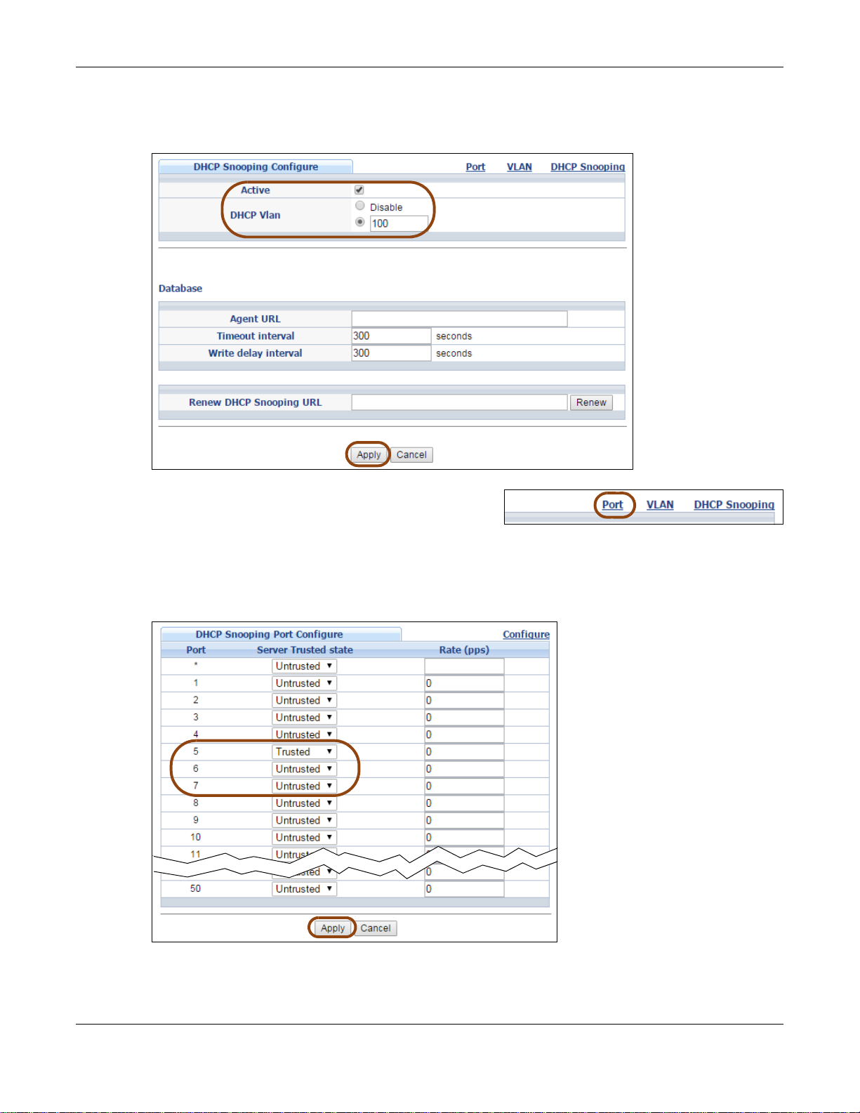
Chapter 6 Tutorials
4 Go to Advanced Application > IP Source Guard > IPv4 Source Guard Setup > DHCP
Snooping > Configure, activate and specify VLAN 100 as the DHCP VLAN as shown. Click Apply.
Figure 44 Tutorial: Specify DHCP VLAN
5 Click the Port link at the top right corner.
6 The DHCP Snooping Port Configure screen appears. Select Trusted in the Server Trusted
state field for port 5 because the DHCP server is connected to port 5. Keep ports 6 and 7
Untrusted because they are connected to DHCP clients. Click Apply.
Figure 45 Tutorial: Set the DHCP Server Port to Trusted
GS2210/XGS2210 Series User’s Guide
51
Page 52
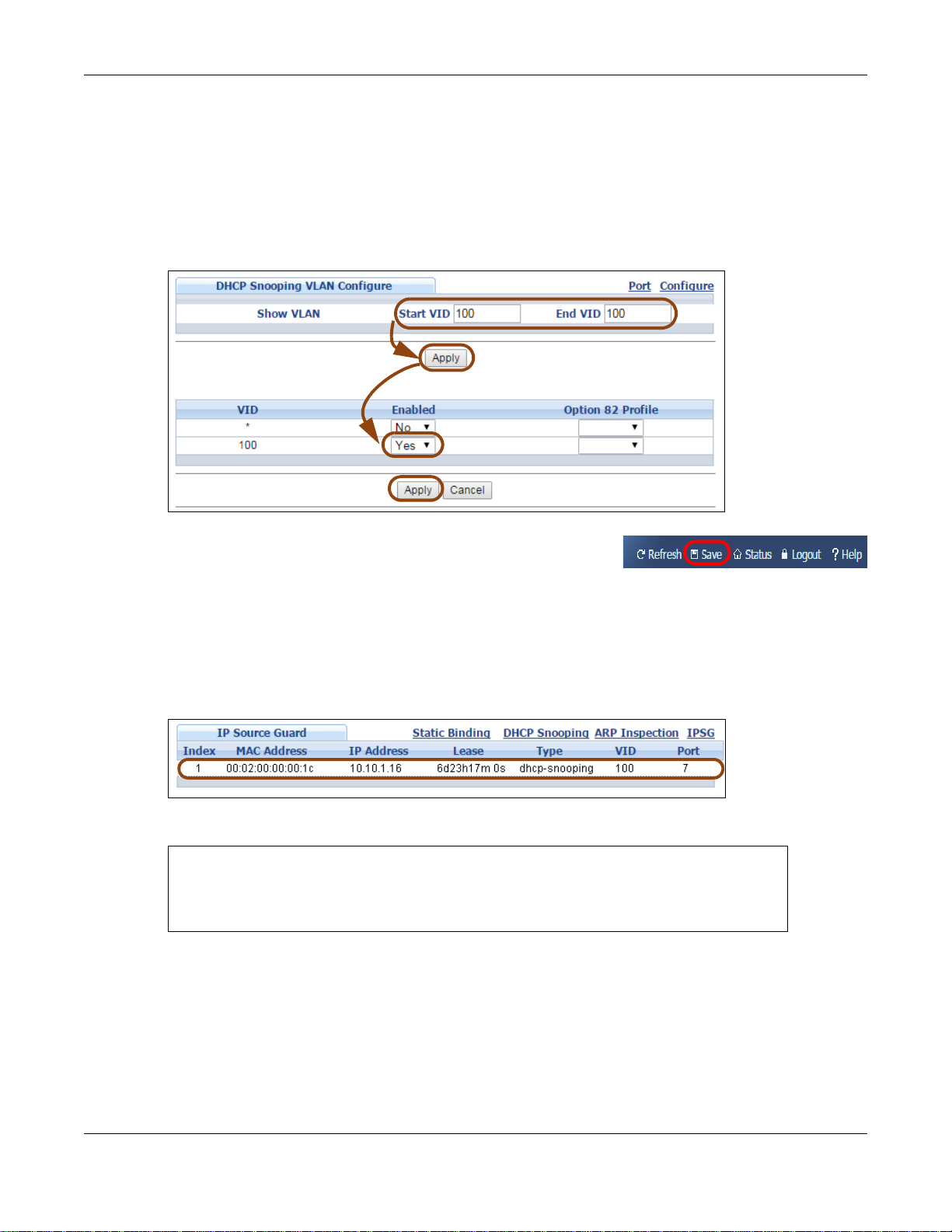
Chapter 6 Tutorials
7 Go to Advanced Application > IP Source Guard > IPv4 Source Guard Setup > DHCP
Snooping > Configure > VLAN, show VLAN 100 by entering 100 in the Start VID and End VID
fields and click Apply. Then select Yes in the Enabled field of the VLAN 100 entry shown at the
bottom section of the screen.
If you want to add more information in the DHCP request packets such as source VLAN ID or
system name, you can also select an Option82 Profile in the entry . See Section 26.19.1.3 on page
264.
Figure 46 Tutorial: Enable DHCP Snooping on this VLAN
8 Click Save at the top right corner of the web configurator to
save the configuration permanently.
9 Connect your DHCP server to port 5 and a computer (as DHCP client) to either port 6 or 7. The
computer should be able to get an IP address from the DHCP server. If you put the DHCP server on
port 6 or 7, the computer will not able to get an IP address.
10 To check if DHCP snooping works, go to Advanced Application > IP Source Guard > IPv4
Source Guard Setup, you should see an IP assignment with the type DHCP-Snooping as shown.
Figure 47 Tutorial: Check the Binding If DHCP Snooping Works
You can also telnet or log into the Switch’s console. Use the command “show dhcp snooping
binding” to see the DHCP snooping binding table as shown next.
sysname# show dhcp snooping binding
MacAddress IpAddress Lease Type VLAN Port
----------------- --------------- ------------ ------------- ---- ---- 00:02:00:00:00:1c 10.10.1.16 6d23h59m20s dhcp-snooping 100 7
Total number of bindings: 1
6.3 How to Use DHCPv4 Relay on the Switch
This tutorial describes how to configure your Switch to forward DHCP client requests to a specific
DHCP server. The DHCP server can then assign a specific IP address based on the information in the
DHCP requests.
GS2210/XGS2210 Series User’s Guide
52
Page 53

Chapter 6 Tutorials
VLAN 102
DHCP Server
Port 2
PVID=102
172.16.1.18
A
192.168.2.3
6.3.1 DHCP Relay Tutorial Introduction
In this example, you have configured your DHCP server (192.168.2.3) and want to have it assign a
specific IP address (say 172.16.1.18) to DHCP client A based on the system name, VLAN ID and
port number in the DHCP request. Client A connects to the Switch’s port 2 in VLAN 102.
Figure 48 Tutorial: DHCP Relay Scenario
6.3.2 Creating a VLAN
Follow the steps below to configure port 2 as a member of VLAN 102.
1 Access the web configurator through the Switch’s management port.
2 Go to Basic Setting > Switch Setup and set the VLAN type to 802.1Q . Click Apply to save the
settings to the run-time memory.
GS2210/XGS2210 Series User’s Guide
53
Page 54

Chapter 6 Tutorials
Figure 49 Tutorial: Set VLAN Type to 802.1Q
3 Click Advanced Application > VLAN > VLAN Configuration > Static VLAN Setup.
4 In the Static VLAN screen, select ACTIVE, enter a descriptive name (VLAN 102 for example) in
the Name field and enter 102 in the VLAN Group ID field.
5 Select Fixed to configure port 2 to be a permanent member of this VLAN.
6 Clear the TX Tagging check box to set the Switch to remove VLAN tags before sending.
7 Click Add to save the settings to the run-time memory. Settings in the run-time memory are lost
when the Switch’s power is turned off.
GS2210/XGS2210 Series User’s Guide
54
Page 55
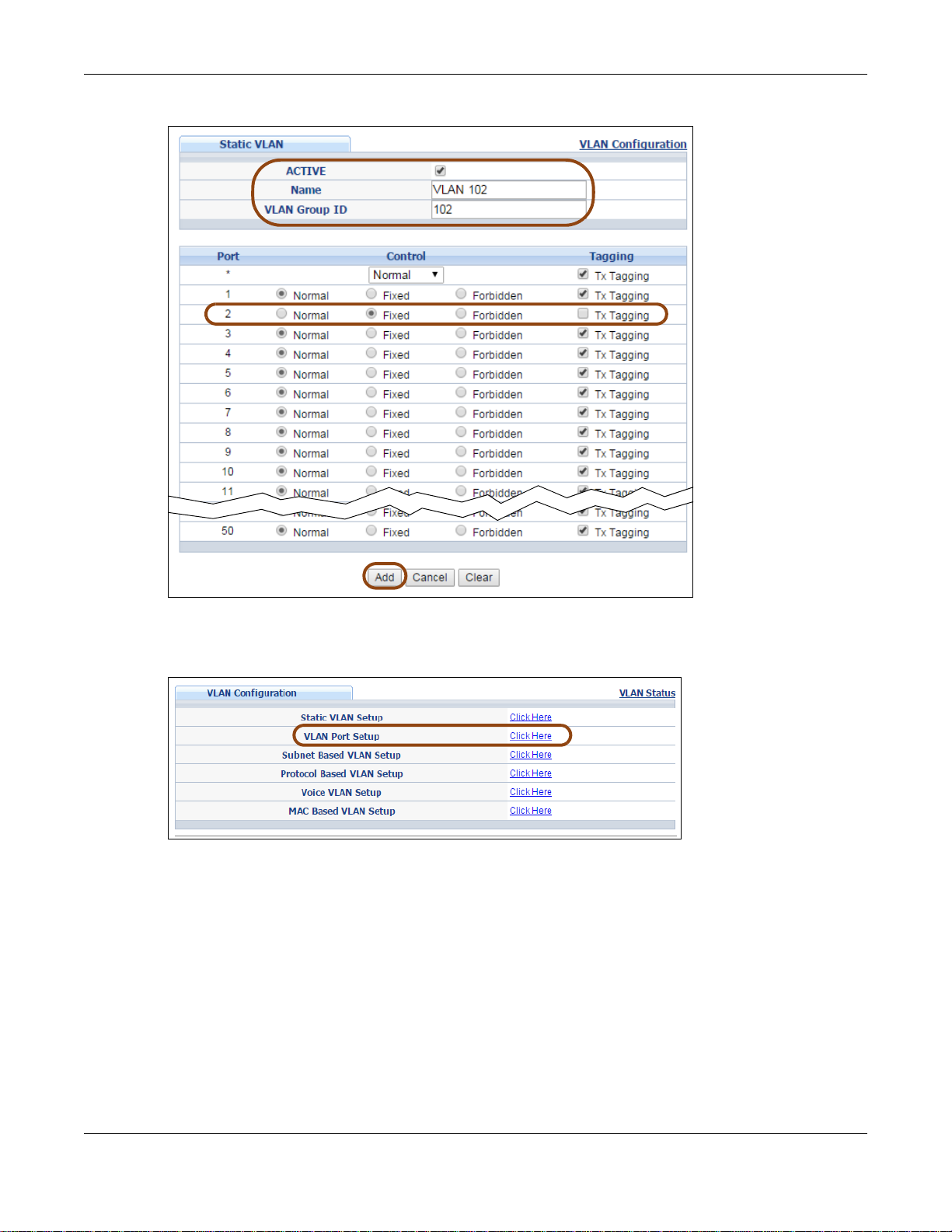
Chapter 6 Tutorials
Figure 50 Tutorial: Create a Static VLAN
8 Click the VLAN Configuration link in the Static VLAN Setup screen and then the VLAN Port
Setup link in the VLAN Configuration screen.
Figure 51 Tutorial: Click the VLAN Port Setting Link
9 Enter 102 in the PVID field for port 2 to add a tag to incoming untagged frames received on that
port so that the frames are forwarded to the VLAN group that the tag defines.
10 Click Apply to save your changes back to the run-time memory.
GS2210/XGS2210 Series User’s Guide
55
Page 56

Chapter 6 Tutorials
Figure 52 Tutorial: Add Tag for Frames Received on Port 2
11 Click the Save link in the upper right corner of the web configurator to save your configuration
permanently.
6.3.3 Configuring DHCPv4 Relay
Follow the steps below to enable DHCP relay on the Switch and allow the Switch to add relay agent
information (such as the VLAN ID) to DHCP requests.
1 Click IP Application > DHCP > DHCPv4 and then the Global link to open the DHCP Relay
screen.
2 Select the Active check box.
3 Enter the DHCP server’s IP address (192.168.2.3 in this example) in the Remote DHCP Server 1
field.
4 Select default1 or default2 in the Option 82 Profile field.
5 Click Apply to save your changes back to the run-time memory.
GS2210/XGS2210 Series User’s Guide
56
Page 57

Figure 53 Tutorial: Set DHCP Server and Relay Information
6 Click the Save link in the upper right corner of the web configurator to save your configuration
permanently.
7 The DHCP server can then assign a specific IP address based on the DHCP request.
6.3.4 Troubleshooting
Check the client A’s IP address. If it did not receive the IP address 172.16.1.18, make sure:
Chapter 6 Tutorials
1 Client A is connected to the Switch’s port 2 in VLAN 102.
2 You configured the correct VLAN ID, port number and system name for DHCP relay on both the
DHCP server and the Switch.
3 You clicked the Save link on the Switch to have your settings take effect.
GS2210/XGS2210 Series User’s Guide
57
Page 58

7.1 Overview
This chapter describes the screens for System Status, ZON Utility, ZON Neighbor Management, Port
Status, and Port Details.
7.1.1 What You Can Do
•Use the Status screen (Section 7.2 on page 58) to see the Switch’s general device information,
system status, and IP addresses. You can also display other status screens for more information.
•Use the ZON Utility screen (Section 7.3 on page 60) to deploy and manage network devices.
•Use the Neighbor screen (Section 7.4 on page 61) to view and manage Switch’s neighbor
devices.
•Use the Port Status Summary screen (Section 7.5 on page 62) to view the port statistics.
•Use the Port Details screen (Section 7.5.1 on page 64) to display individual port statistics.
CHAPTER 7
Status and ZON
7.2 Status
The Status screen displays when you log into the Switch or click Status at the top right corner of
the web configurator. The Status screen displays general device information, system status, and its
IP addresses.
GS2210/XGS2210 Series User’s Guide
58
Page 59
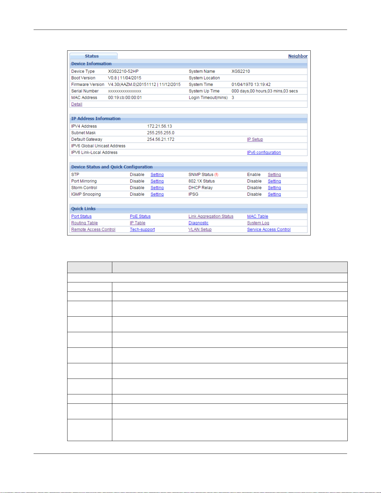
Chapter 7 Status and ZON
Figure 54 Status (for PoE model(s))
The following table describes the labels in this screen.
Table 8 Status
LABEL DESCRIPTION
Device Information
Device Type This field displays the model name of this Switch.
System Name This field displays the name used to identify the Switch on any network.
Boot Version This field displays the version number and date of the boot module that is currently on the
System
Location
Firmware
Version
System Time This field displays the current date and time in the UAG. The format is mm-dd-yyyy
Serial Number This field displays the serial number of this Switch. The serial number is used for device
System Up
Time
MAC Address This field displays the MAC addresses of the Switch.
Login Timeout This field displays how many minutes a management session can be left idle before the
Detail Click this link to go to the Basic Setting > System Info screen to check other detailed
Switch.
This field displays the geographic location of your Switch. You can change the setting in the
Basic Setting > General Setup screen.
This field displays the version number and date of the firmware the Switch is currently
running.
hh:mm:ss.
tracking and control.
This field displays how long the Switch has been running since it last restarted or was turned
on.
session times out. After it times ou t you have to log in with your password again.
information, such as system resource usage and the Switch temperature, fan speeds or
voltage.
GS2210/XGS2210 Series User’s Guide
59
Page 60
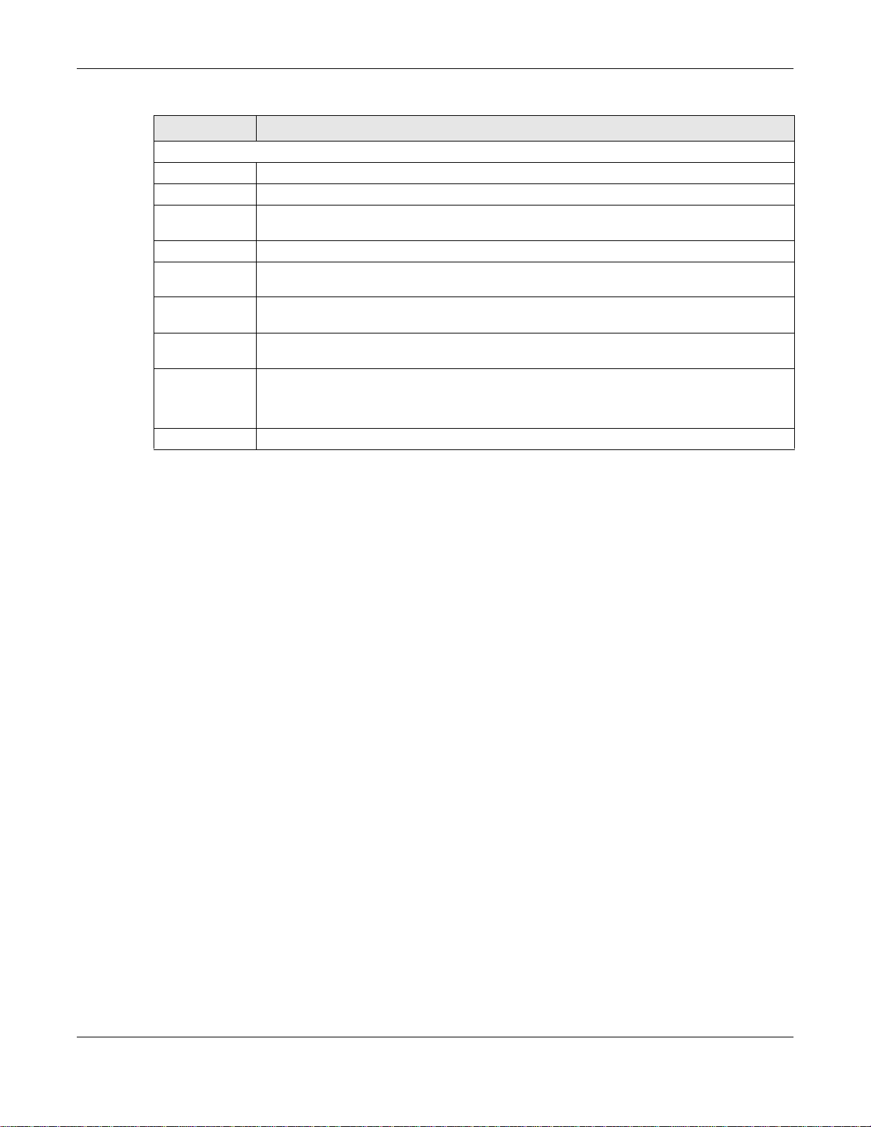
Chapter 7 Status and ZON
Table 8 Status (continued)
LABEL DESCRIPTION
IP Address Information
IPv4 Address This field displays the Switch’s current IPv4 address.
Subnet Mask This field displays the Switch’s subnet mask.
Default
Gateway
IP Setup Click the link to go to the Basic Setting > IP Setup screen.
IPV6 Global
Unicast Address
IPV6 Link -L o cal
Address
IPv6
configuration
Device Status
and Quick
Configuration
Quick Links This section provides the shortcut link to a specific cofiguration screen.
This field displays the IP address of the Switch’s default gateway.
This field displays the Switch’s IPv6 global unicast address
This field displays the Switch’s IPv6 link-local address.
Click the link to go to the Basic Setting > IPv6 screen.
This section shows whether a feature is enabled or not on the Switch. You can click a
feature’s Setting link to go to the configuration screen for the feature.
Hover your cursor over a red exclamation mark to display information about the feature.
7.3 ZyXEL One Network (ZON) Utility Screen
ZON Utility is a program designed to help you deploy and manage a network more efficiently. It
detects devices automatically and allows you to do basic settings on devices in the network without
having to be near it.
The ZON Utility issues requests via ZyXEL Discovery Protocol (ZDP) and in response to the query,
the device responds back with basic information including IP address, firmware version, location,
system and model name in the same broadcast domain. The information is then displayed in the
ZON Utility screen and you can perform tasks like basic configuration of the devices and batch
firmware upgrade in it. You can download the ZON Utility at www.zyxel.com and install it on a PC.
The following figure shows the ZON Utility screen.
GS2210/XGS2210 Series User’s Guide
60
Page 61
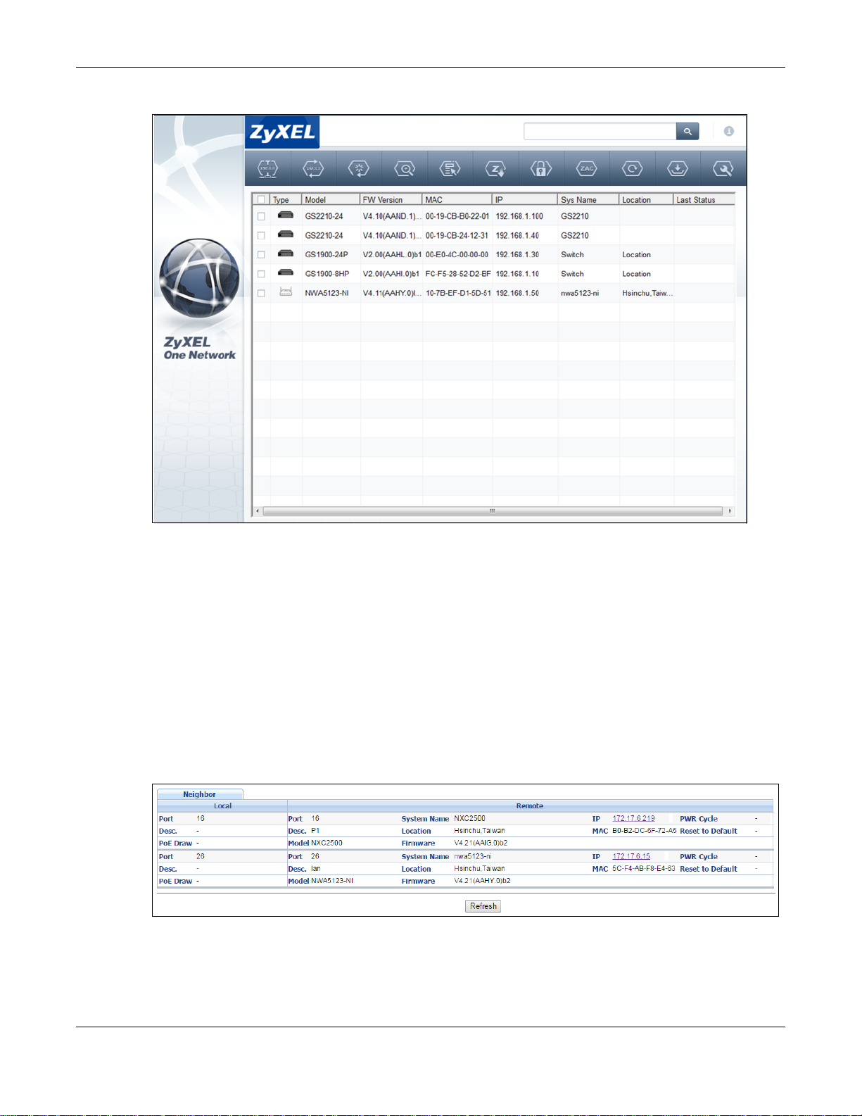
Figure 55 ZON Utility Screen
Chapter 7 Status and ZON
7.4 ZON Neighbor Management Screen
The ZON neighbor management screen allows you to view and manage the Switch’s neighboring
devices more conveniently. It uses Layer Link Discovery Protocol (LLDP) to discover all neighbor
devices connected to the Switch including non-ZyXEL devices. You can perform tasks on the
neighboring devices like login, reboot (turn the power off and then back on again), and reset to
factory default settings in the Neighbor Management screen. For more information on LLDP, see
(Section 35.1 on page 301).
Click Status > Neighbor to see the following screen.
Figure 56 Status > Neighbor
GS2210/XGS2210 Series User’s Guide
61
Page 62
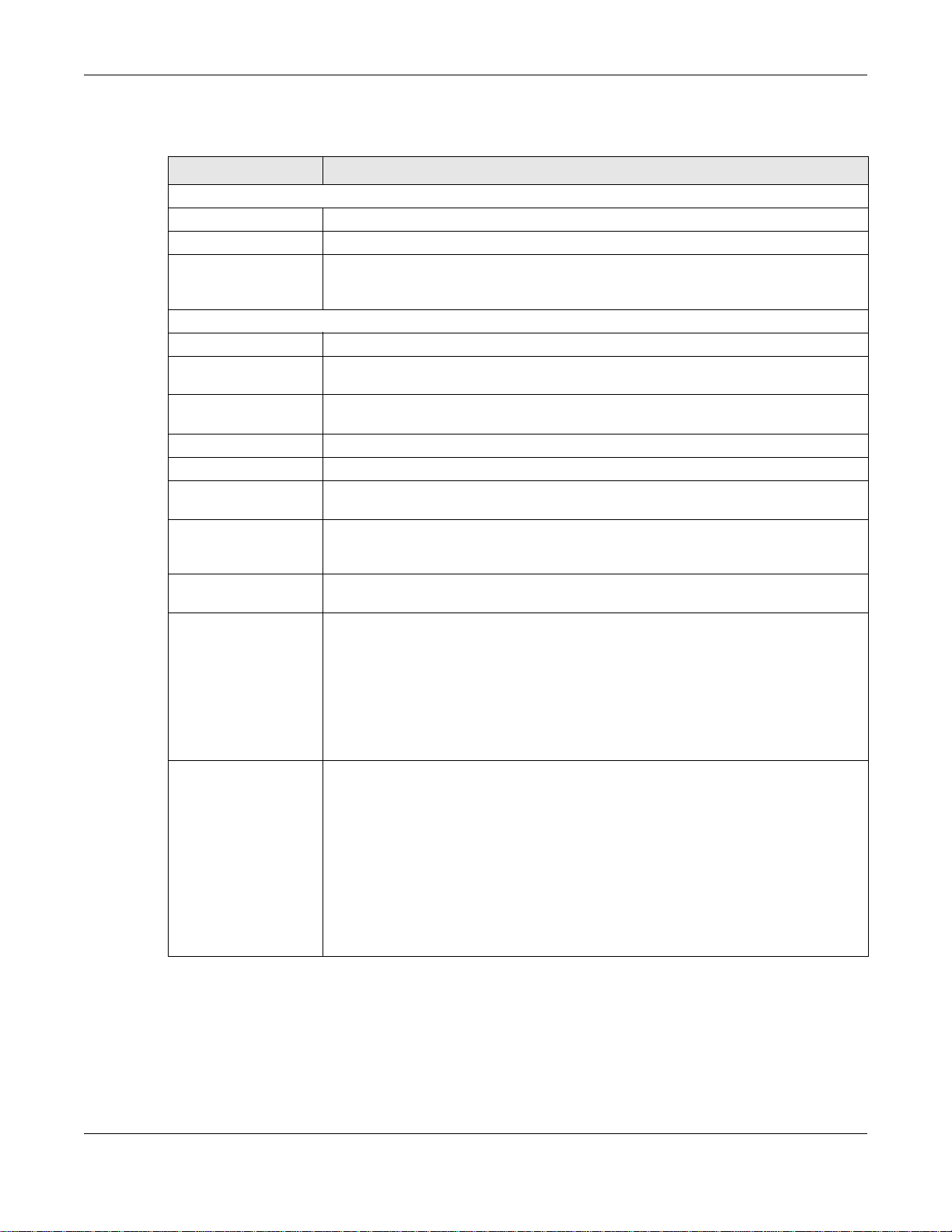
Chapter 7 Status and ZON
The following table describes the fields in the above screen.
Table 9 Status > Neighbor
LABEL DESCRIPTION
Local
Port This shows the port of the Switch, on which the neighboring device is discovered.
Desc. This shows the port description of the Switch.
PoE Draw This shows the consumption that the neighboring device connected to this port draws
Remote
Port This show the number of the neighbor device’s port which is connected to the Switch.
Desc. This shows the description of the neighbor device’s port which is connected to the
Model This shows the model name of the neighbor device. This field will show “-” for non-
System Name This shows the system name of the neighbor device.
Location This shows the geographic location of the neighbor device.
Firmware This shows the firmware version of the neighbor device. This field will show “-” for
IP This shows the IP address of the neighbor device. The IP address is a hyper link that
MAC This shows the MAC address of the neighbor device. This field will show “-” for non-
PWR Cycle Click the Cycle button to turn OFF the power of the neighbor device and turn it back
from the Switch. This allows you to plan and use within the power budget of the
Switch.
Switch.
ZyXEL devices.
non-ZyXEL devices.
you can click to log into and manage the neighbor device through its web
configurator. This field will show “-” for non-ZyXEL devices.
ZyXEL devices.
ON again. A count down button (from 5 to 0) starts.
Reset to Default Click the Reset button to reset the neighbor device to its factory default settings. A
7.5 Port Status
This screen displays a port statistical summary with links to each port showing statistical details. T o
view the port statistics, click Status in all web configurator screens and then the Port Status link
Note:
• The Switch must support power sourcing (PSE) or the network device is a
powered device (PD).
• If multiple neighbor devices use the same port, the Cycle button is displayed only
on the first device, others will show “-” instead.
warning message “Are you sure you want to load factory default?” appears
prompting you to confirm the action. After confirming the action a count down button
(from 5 to 0) starts.
Note:
• The Switch must support power sourcing (PSE) or the network device is a
powered device (PD).
• If multiple neighbor devices use the same port, the Reset button is not av ai lable
and will show “-” instead.
• You can only reset ZyXEL products.
GS2210/XGS2210 Series User’s Guide
62
Page 63

Chapter 7 Status and ZON
in the Quick Links section of the Status screen to display the Port Status screen as shown next.
You can also click Management > Port Status to see the following screen.
Figure 57 Port Status (for PoE model(s))
The following table describes the labels in this screen.
Table 10 Port Status
LABEL DESCRIPTION
Port This identifies the Ethernet port. Click a port number to display the Port Details screen
Name This is the name you assigned to this port in the Basic Setting > Port Setup screen.
Link This field displays the speed (either 10M for 10Mbps, 100M for 100Mbps or 1000M for
State If STP (Spanning Tree Protocol) is enabled, this field displays the STP state of the port. See
PD For PoE model(s) only.
LACP This fields displays whether LACP (Link Aggregation Control Protocol) has been enabled on
TxPkts This field shows the number of transmitted frames on this port.
RxPkts This field shows the number of received frames on this port.
Errors This field shows the number of received errors on this port.
Tx KB/s This field shows the number of kilobytes per second transmitted on this port.
(refer to Figure 58 on page 64).
1000Mbps) and the duplex (F for full duplex or H for half). It also shows the cable type
(Copper or Fiber) for the combo ports.
Section 13.1 on page 130 for more information.
If STP is disabled, this field displays FORWARDING if the link is up, otherwise, it displays
STOP.
This field displays whether or not a powered device (PD) is allowed to receive power from
the Switch on this port.
the port.
GS2210/XGS2210 Series User’s Guide
63
Page 64

Table 10 Port Status (continued)
LABEL DESCRIPTION
Rx KB/s This field shows the number of kilobytes per second received on this port.
Up Time This field shows the total amount of time in hours, minutes and seconds the port has been
Clear Counter Select Port, enter a port number and then click Clear Counter to erase the recorded
7.5.1 Port Details
Click a number in the Port column in the Port Status screen to display individual port statistics.
Use this screen to check status and detailed performance data about an individual port on the
Switch.
Figure 58 Port Status > Port Details
Chapter 7 Status and ZON
up.
statistical information for that port, or select Any to clear statistics for all ports.
GS2210/XGS2210 Series User’s Guide
64
Page 65

Chapter 7 Status and ZON
The following table describes the labels in this screen.
Tab le 11 Port Status: Port Details
LABEL DESCRIPTION
Port Info
Port NO. This field displays the port number you are viewing.
Name This field displays the name of the port.
Link This field displays the speed (either 10M for 10Mbps, 100M for 100Mbps or 1000M for
Status If STP (Spanning Tree Protocol) is enabled, this field displays the STP state of the port. See
LACP This field shows if LACP is enabled on this port or not.
TxPkts This field shows the number of transmitted frames on this port
RxPkts This field shows the number of received frames on this port
Errors This field shows the number of received errors on this port.
Tx KB/s This field shows the number of kilobytes per second transmitte d on this port.
Rx KB/s This field shows the number of kilobytes per second received on this port.
Up Time This field shows the total amount of time the connection has been up.
Tx Packet
The following fields display detailed information about packets transmitted.
Unicast This field shows the number of good unicast packets transmitted.
Multicast This field shows the number of good multicast packets transmitted.
Broadcast This field shows the number of good broadcast packets transmitted.
Pause This field shows the number of 802.3x Pause packets transmitted.
Tagged This field shows the number of packets with VLAN tags transmitted.
Rx Packet
1000Mbps) and the duplex (F for full duplex or H for half duplex). It also shows the cable type
(Copper or Fiber) for the combo ports.
Section 13.1 on page 130 for more information.
If STP is disabled, this field displays FORWARDING if the link is up, otherwise, it displays
STOP.
The following fields display detailed information about packets received.
Unicast This field shows the number of good unicast packets received.
Multicast This field shows the number of good multicast packets received.
Broadcast This field shows the number of good broadcast packets received.
Pause This field shows the number of 802.3x Pause packets received.
Control This field shows the number of control packets received (including those with CRC error ) but it
TX Collision
The following fields display info rmation on collisions while transmitting .
Single This is a count of successfully transmitted packets for which transmission is inhibited by
Multiple This is a count of successfully transmitted packets for which transmission was inhibited by
Excessive This is a count of packets for which transmission failed due to excessive collisions. Excessive
does not include the 802.3x Pause packets.
exactly one collision.
more than one collision.
collision is defined as the number of maximum collisions before the retransmission count is
reset.
GS2210/XGS2210 Series User’s Guide
65
Page 66

Chapter 7 Status and ZON
Tab le 11 Port Status: Port Details (continued)
LABEL DESCRIPTION
Late This is the number of times a late collision is detected, that is, after 512 bits of the packets
have already been transmitted.
Error Packet The following fields display detailed information about packets received that were in error.
RX CRC This field shows the number of packets received with CRC (Cyclic Redundant Check) error(s).
Length This field shows the number of packets received with a length that was out of range.
Runt This field shows the number of packets re ceiv ed that were too short (sh orter th an 64 oct ets),
including the ones with CRC errors.
Distribution
64 T his field shows the number of packets (including bad packets) received that were 64 octets
65-127 This field shows the numb er of packets (including bad packets) received that were between
128-255 This field shows the number of packets (including bad packets) received that were between
256-511 This field shows the number of packets (including bad packets) received that were between
512-1023 This field shows the number of packets (including bad packets) received that were between
10241518
Giant T his field shows the number of packets (including bad packets) received that were between
in length.
65 and 127 octets in length.
128 and 255 octets in length.
256 and 511 octets in length.
512 and 1023 octets in length.
This field shows the number of packets (including bad packets) received that were between
1024 and 1518 octets in length.
1519 octets and the maximum frame size.
The maximum frame size varies depending on your switch model.
GS2210/XGS2210 Series User’s Guide
66
Page 67

8.1 Overview
This chapter describes how to configure the System Info, General Setup, Switch Setup, IP
Setup, Port Setup, PoE, Interface Setup and IPv6 screens.
8.1.1 What You Can Do
•Use the System Info screen (Section 8.2 on page 67) to check the firmware version number.
•Use the General Setup screen (Section 8.3 on page 69) to configure general settings such as
the system name and time.
•Use the Switch Setup screen (Section 8.5 on page 72) to choose your VLAN type, set the GARP
timers and assign priorities to queues.
•Use the IP Setup screen (Section 8.6 on page 73) to configure the Switch IP address, default
gateway device, and the management VLAN ID.
•Use the Port Setup screen (Section 8.7 on page 77) to configure Switch port settings.
•Use the PoE Status screens (Section 8.8 on page 79) to view the current amount of power that
PDs are receiving from the Switch and set the priority levels for the Switch in distributing power
to PDs. This screen is available for PoE model(s) only.
•Use the Interface Setup screens (Section 8.9 on page 85) to configure Switch interface type
and interface ID settings.
•Use the IPv6 screens (Section 8.10 on page 86) to view IPv6 status and IPv6 configuration.
•Use the DNS screen (Section 8.11 on page 99) to configure the default domain name server.
CHAPTER 8
Basic Setting
8.2 System Information
In the navigation panel, click Basic Setting > System Info to display the screen as shown. Use
this screen to view general system information. You can check the firmware version number.
GS2210/XGS2210 Series User’s Guide
67
Page 68
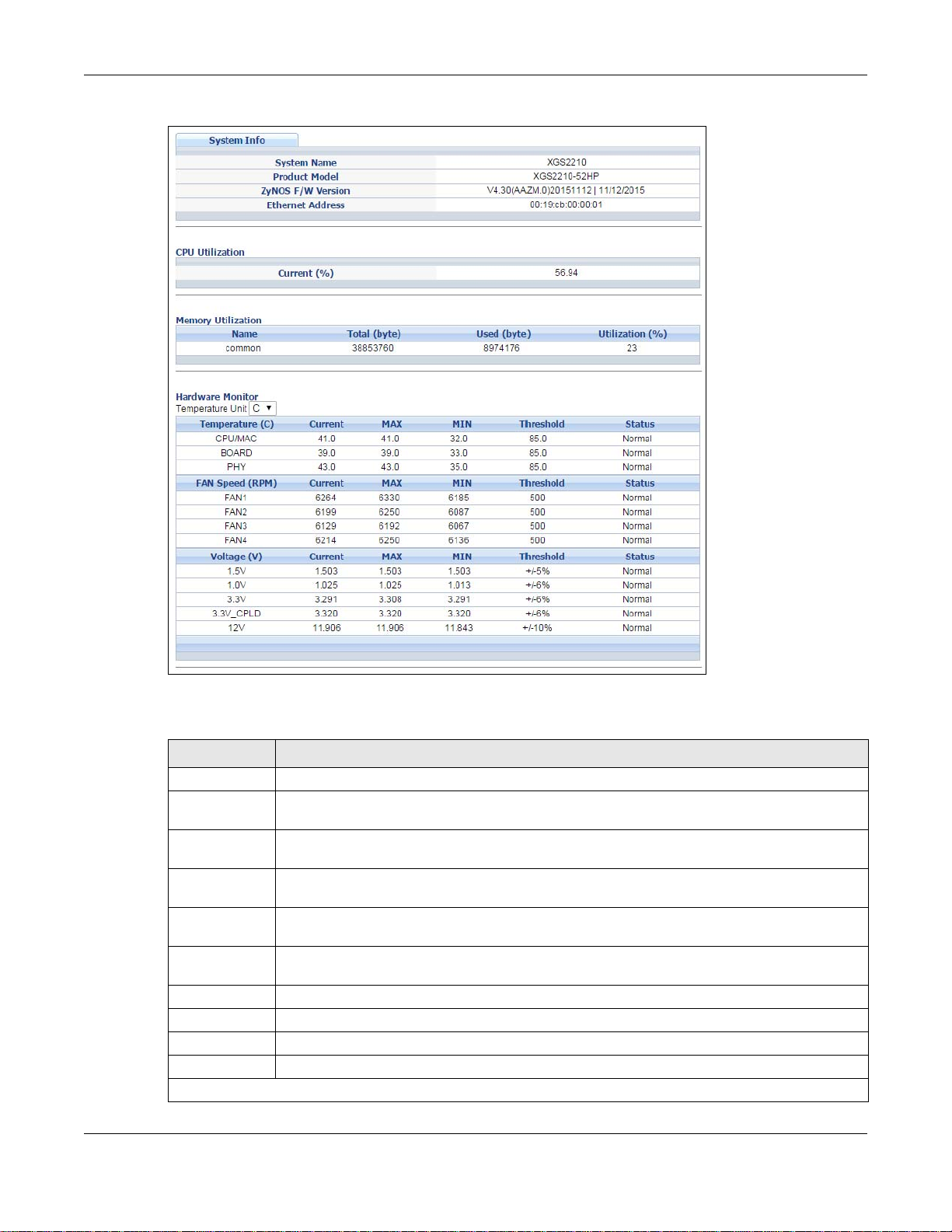
Chapter 8 Basic Setting
Figure 59 Basic Setting > System Info (for PoE model(s) only)
The following table describes the labels in this screen.
Table 12 Basic Setting > System Info
LABEL DESCRIPTION
System Name This field displays the descriptive name of the Switch for identification purposes.
Product Model This field displays the product model of the Switch. Use this infor mation when searching for
ZyNOS F/W
Version
Ethernet
Address
CPU Utilization CPU utilization quantifies how busy the system is. Current (%) displays the current
Memory
Utilization
Name This field displays the name of memory pool.
Total This field displays the total number of bytes in this memory pool.
Used This field displays the number of bytes being used in this memory pool.
Utilization This field displays the percentage (%) of memory being used in this memory pool.
Hardware Monitor
firmware upgrade or looking for other support information in the website.
This field displays the version number of the Switch 's current firmware including the date
created.
This field refers to the Ethernet MAC (Media Access Control) address of the Switch.
percentage of CPU utilization.
Memory utilization shows how much DRAM memory is available and in use. It also displays
the current percentage of memory utilization.
GS2210/XGS2210 Series User’s Guide
68
Page 69

Chapter 8 Basic Setting
Table 12 Basic Setting > System Info (continued)
LABEL DESCRIPTION
Temperature
Unit
Temperature BOARD, MAC and PHY refer to the location of the temperature sensors on the Switch
Current This shows the current temperature at this sensor.
MAX This field displays the maximum temperature measured at this sensor.
MIN This field displays the minimum temperature measured at this sensor.
Threshold This field displays the upper temperature limit at this sensor.
Status This field displays Normal for temperatures below the threshold and Error for those above.
Fan Speed
(RPM)
Current This field displays this fan's current speed in Revolutions Per Minute (RPM).
MAX This field displays this fan's maximum speed measured in Revolutions Per Minute (RPM).
MIN This field displays this fan's minimum speed measured in Revolutions Per Minute (RPM).
Threshold This field displays the minimum speed at which a normal fan should work.
Status Normal indicates that this fan is functioning above the minimum spe ed. Error indicates that
Voltage(V) The power supply for each voltage has a sensor that is capable of detecting and reporting if
Current This is the current voltage reading.
MAX This field displays the maximum voltage measured at this point.
MIN This field displays the minimum voltage measured at this point.
Threshold This field displays the percentage tolerance of the voltage with which the Switch still works.
Status Normal indicates that the voltage is within an acceptable operating range at this point;
The Switch has temperature sensors that are capable of detecting and reporting if the
temperature rises above the threshold. You may choose the temperature unit (Centigrade or
Fahrenheit) in this field.
printed circuit board.
A properly functioning fan is an essential component (along with a sufficiently ventilated,
cool operating environment) in order for the device to sta y within the temper ature threshold.
Each fan has a sensor that is capable of detecting and reporting if the fan speed falls belo w
the threshold shown.
"<41" is displayed for speeds too small to measure (under 2000 RPM).
this fan is functioning below the minimum speed.
the voltage falls out of the tolerance range.
otherwise Error is displayed.
8.3 General Setup
Use this screen to configure general settings such as the system name and time. Click Basic
Setting > General Setup in the navigation panel to display the screen as shown.
GS2210/XGS2210 Series User’s Guide
69
Page 70

Chapter 8 Basic Setting
Figure 60 Basic Setting > General Setup
The following table describes the labels in this screen.
Table 13 Basic Setting > General Setup
LABEL DESCRIPTION
System Name Choose a descriptive name for identification purposes. This name consists of up to 64
printable characters; spaces are allowed.
Location Enter the geographic location of your Switch. You can use up to 32 printable ASCII
characters; spaces are allowed.
Contact Person's
Name
Use Time Server
when Bootup
Time Server IP
Address
Current Time This field displays the time you open this menu (or refresh the menu).
New Time
(hh:min:ss)
Current Date This field displays the date you open this menu.
New Date (yyyy-
mm-dd)
Enter the name of the person in charge of this Switch. You can use up to 32 printable
ASCII characters; spaces are allowed.
Enter the time service protocol that your time server uses. Not all time servers support all
protocols, so you may have to use trial and error to find a protocol that works. The main
differences between them are the time format.
When you select the Daytime (RFC 867) format, the Switch displays the day, month,
year and time with no time zone adjustment. When you use this format it is recommended
that you use a Daytime timeserver within your geographical time zone.
Time (RFC-868) format displays a 4-byte integer giving the total number of seconds
since 1970/1/1 at 0:0:0.
NTP (RFC-1305) is similar to Time (RFC-868).
None is the default value. Enter the time manually. Each time you turn on the Switch, the
time and date will be reset to 1970-1-1 0:0:0.
Enter the IP address of your timeserver. The Switch searches for the timeserver for up to
60 seconds. If you select a timeserver that is unreachable, then this screen will appear
locked for 60 seconds. Please wait.
Enter the new time in hour, minute and second format. The new time then appears in the
Current Time field after you click Apply.
Enter the new date in year, month and day format. The new date then appears in the
Current Date field after you click Apply.
GS2210/XGS2210 Series User’s Guide
70
Page 71

Chapter 8 Basic Setting
Table 13 Basic Setting > General Setup (continued)
LABEL DESCRIPTION
Time Zone Select the time difference between UTC (Universal Time Coordinated, formerly known as
GMT, Greenwich Mean Time) and your time zone from the drop-down list box.
Daylight Saving
Time
Start Date Configure the day and time when Daylight Saving Time starts if you selected Daylight
End Date Configure the day and time when Daylight Saving Time ends if you selected Daylight
Apply Click Apply to save your changes to the Switch’s run-time memory. The Switch loses
Cancel Click Cancel to begin configuring this screen afresh.
Daylight saving is a period from late spring to early fall when many countries set their
clocks ahead of normal local time by one hour to give more daytime light in the evening.
Select this option if you use Daylight Saving Time.
Saving Time. The time is displayed in the 24 hour format. Here are a couple of examples:
Daylight Saving Time starts in most parts of the United States on the second Sunday of
March. Each time zone in the United States starts using Daylight Saving Time at 2 A.M.
local time. So in the United States yo u would select Second, Sunday, March and 2:00.
Daylight Saving Time starts in the European Union on the last Sunday of March. All of the
time zones in the European Union start using Daylight Saving Time at the same moment
(1 A.M. GMT or UTC). So in the European Union you would select Last, Sunday, March
and the last field depends on your time zone. In Germany for instance, you would select
2:00 because Germany's time zone is one hour ahead of GMT or UTC (GMT+1).
Saving Time. The time field uses the 24 hour format. Here are a couple of examples:
Daylight Saving Time ends in the United States on the first Sunday of November. Each
time zone in the United States stops using Daylight Saving Time at 2 A.M. local time. So in
the United States you would select First, Sunday, November and 2:00.
Daylight Saving Time ends in the European Union on the last Sunday of October. All of the
time zones in the European Union stop using Daylight Saving Time at the same moment (1
A.M. GMT or UTC). So in the European Union you would select Last, Sunday, October
and the last field depends on your time zone. In Germany for instance, you would select
2:00 because Germany's time zone is one hour ahead of GMT or UTC (GMT+1).
these changes if it is turned off or loses power, so use the Save link on the top navigation
panel to save your changes to the non-volatile memory when you are done configuring.
8.4 Introduction to VLANs
A VLAN (Virtual Local Area Network) allows a physical network to be partitioned into multiple logical
networks. Devices on a logical network belong to one group. A device can belong to more than one
group. With VLAN, a device cannot directly talk to or hear from devices that are not in the same
group(s); the traffic must first go through a router.
In MTU (Multi-Tenant Unit) applications, VLAN is vital in providing isolation and security among the
subscribers. When properly configured, VLAN prevents one subscriber from accessing the network
resources of another on the same LAN, thus a user will not see the printers and hard disks of
another user in the same building.
VLAN also increases network performance by limiting broadcasts to a smaller and more
manageable logical broadcast domain. In traditional switched environments, all broadcast packets
go to each and every individual port. With VLAN, all broadcasts are confined to a specific broadcast
domain.
Note: VLAN is unidirection al; it only governs outgoing traffic.
GS2210/XGS2210 Series User’s Guide
71
Page 72
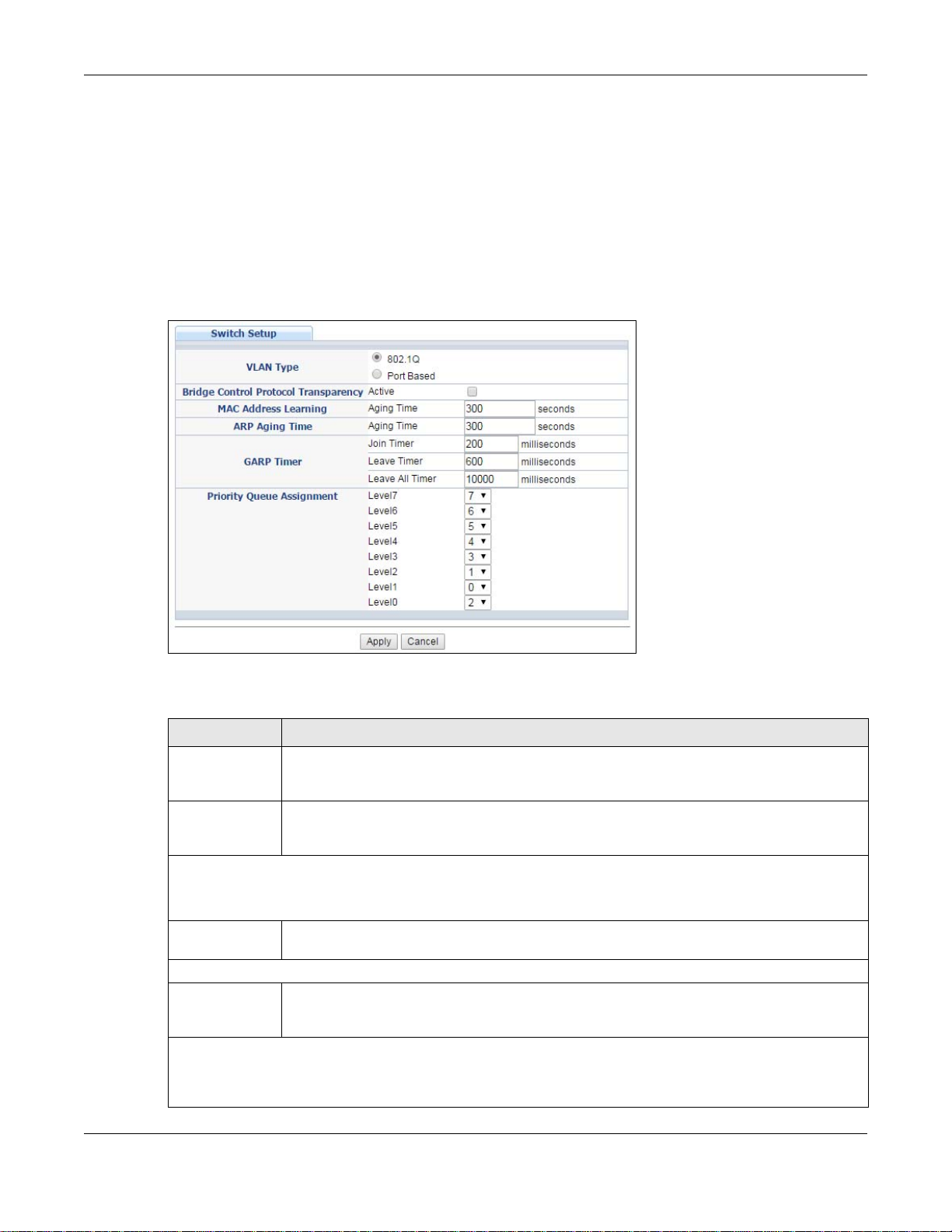
See Chapter 9 on page 101 for information on port-based and 802.1Q tagged VLANs.
8.5 Switch Setup
Click Basic Setting > Switch Setup in the navigation panel to display the screen as shown. The
VLAN setup screens change depending on whether you choose 802.1Q or Port Based in the VLAN
Type field in this screen. Refer to Chapter 9 on page 101 for more information on VLAN.
Figure 61 Basic Setting > Switch Setup
Chapter 8 Basic Setting
The following table describes the labels in this screen.
Table 14 Basic Setting > Switch Setup
LABEL DESCRIPTION
VLAN Type Choose 802.1Q or Port Based. The VLAN Setup screen changes depending on whether
you choose 802.1Q VLAN type or Port Based VLAN type in this screen. See
page 101
Bridge Control
Protocol
Transparency
MAC Address Learning
MAC address learning reduces outgoing traffic broadcasts. For MAC address learning to occur on a port, the
port must be active.
Aging Time Enter a time from 10 to 1000000 seconds. This is how long all dynamically learned MAC
ARP Aging Time
Aging Time Enter a time from 60 to 1000000 seconds. This is how long dynamically learne d ARP entries
GARP Timer: Switches join VLANs by making a declaration. A declaration is made by issuing a Join message
using GARP. Declarations are withdrawn by issuing a Leave message. A Leave All message terminates all
registrations. GARP timers set declaration timeout values. See the chapter on VLAN setup for more
background information.
Select Active to allow the Switch to handle bridging control protocols (STP, for example).
You also need to define how to treat a BPDU in the Port Setup screen.
addresses remain in the MAC address table before they age out (and must be relearned).
remain in the ARP table before they age out (and must be relearned). The setting here
applies to ARP entries which are newly added in the ARP table after you click Apply.
for more information.
Chapter 9 on
GS2210/XGS2210 Series User’s Guide
72
Page 73

Chapter 8 Basic Setting
Table 14 Basic Setting > Switch Setup (continued)
LABEL DESCRIPTION
Join Timer Join Timer sets the duration of the Join Period timer for GVRP in milliseconds. Eac h port has
a Join Period timer. The allowed Join Time range is between 100 and 65535 milliseconds;
the default is 200 milliseconds. See the chapter on VLAN setup for more background
information.
Leave Timer Leave Time sets the duration of the Leave Period timer for GVRP in milliseconds. Each port
has a single Leave Period timer. Leave Time must be two times larger than Join Timer;
the default is 600 milliseconds.
Leave All Timer Leave All Timer sets the duration of the Leave All Period timer for GVRP in milliseconds.
Priority Queue Assignment
IEEE 802.1p defines up to eight separate traffic types by inserting a tag into a MAC-layer frame that contains
bits to define class of service. Frames without an explicit priority tag are given the default priority of the
ingress port. Use the next fields to configure the priority level-to-physical queue mapping.
The Switch has eight physical queues that you can map to the 8 priority levels. On the Switch, traffic assigned
to higher index queues gets through faster while traffic in lower index queues is dropped if the network is
congested.
Priority Level (The following descriptions are based on the traffic types defined in the IEEE 802.1d standard
(which incorporates the 802.1p).
Level 7 Typically used for network control traffic such as router configuration messages.
Level 6 Typically used for voice traffic that is especially sensitive to jitter (jitter is the variations in
Level 5 Typically used for video that consumes high bandwidth and is sensitive to jitter.
Level 4 Typically used for controlled load, latency-sensitive traffic such as SNA (Systems Network
Level 3 Typically used for “excellent effort” or better than best effort and would include important
Level 2 This is for “spare bandwidth”.
Level 1 This is typically used for non-critical “background” traffic such as bulk transfers that are
Level 0 Typically used for best-effort traffic.
Apply Click Apply to save y our ch anges t o the S wi tch ’s run-time memory. The Switch loses these
Cancel Click Cancel to reset the fields.
Each port has a single Leave All Period timer. Leave All Timer must be larger than Leave
Timer.
delay).
Architecture) transactions.
business traffic that can tolerate some delay.
allowed but that should not affect other applications and users.
changes if it is turned off or loses power, so use the Save link on the top navigation panel to
save your changes to the non-volatile memory when you are done configuring.
8.6 IP Setup
Use the IP Setup screen to configure the Switch IP address, default gateway device, and the
management VLAN ID. The default gateway specifies the IP address of the default gateway (next
hop) for outgoing traffic.
GS2210/XGS2210 Series User’s Guide
73
Page 74
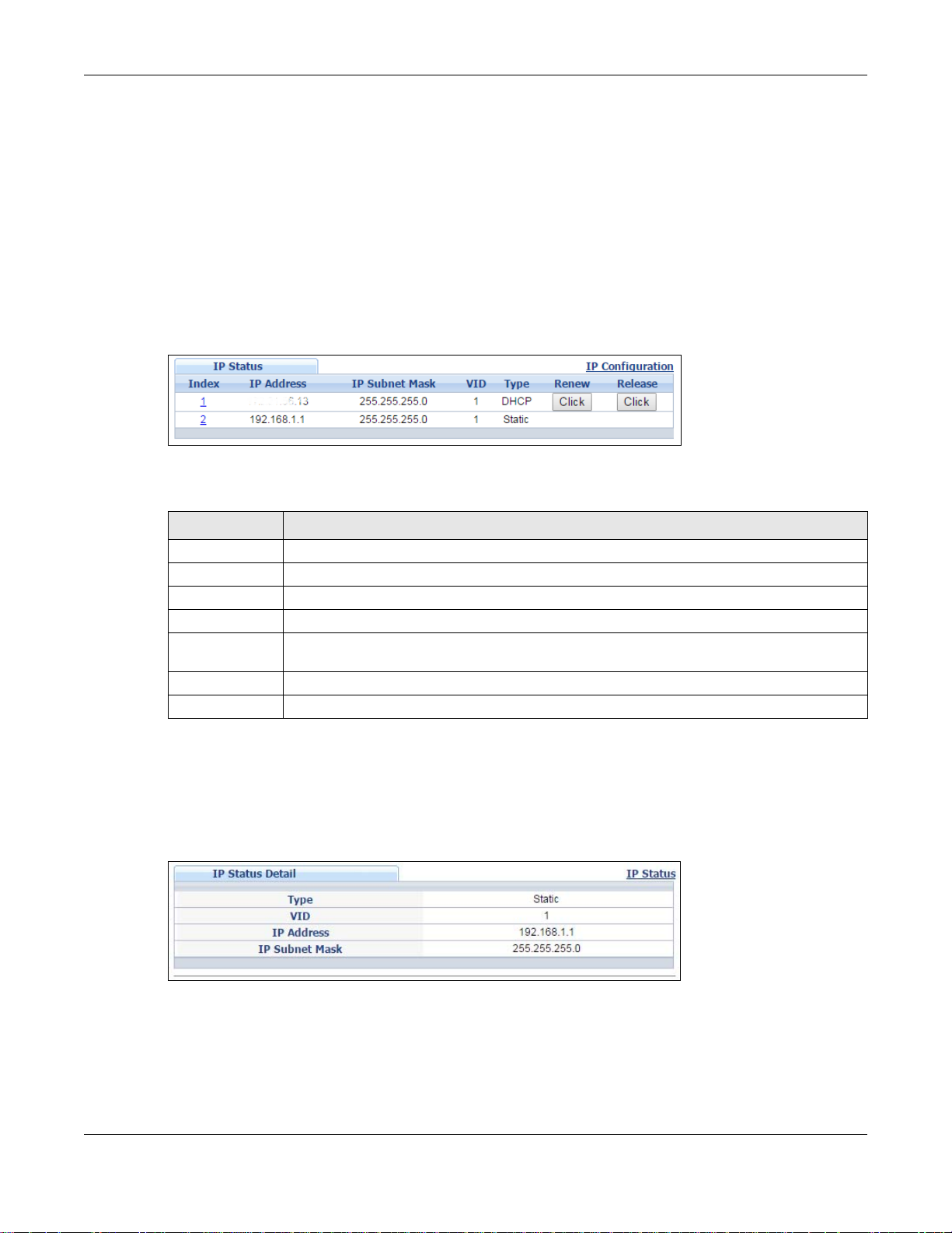
Chapter 8 Basic Setting
8.6.1 Management IP Addresses
The Switch needs an IP address for it to be managed over the network. The factory default IP
address is 192.168.1.1. The subnet mask specifies the network number portion of an IP address.
The factory default subnet mask is 255.255.255.0.
You can configu re up to 32 IP addresses which are used to access and manage the S witch from the
ports belonging to the pre-defined VLAN(s).
Note: You must configure a VLAN first. Each VLAN can only have one management IP
address.
Figure 62 Basic Setting > IP Setup
The following table describes the labels in this screen.
Table 15 Basic Setting > IP Setup
LABEL DESCRIPTION
Index This field displays the index number of an entry.
IP Address This field displays IP address of the Switch in the IP domain.
IP Subnet Mask This field displays the subnet mask of the Switch in the IP domain.
VID This field displays the VLAN identification number of the IP domain on the Switch.
Type This shows whether this IP address is dynamically assigned from a DHCP server or
manually assigned (Static).
Renew Click this to renew the dynamic IP address.
Release Click this to release the dynamic IP address.
8.6.2 IP Status Details
Use this screen to view IP status details. Click a number in the Index column in the IP Status
screen to display the screen as shown next.
Figure 63 Basic Setting > IP Setup > IP Status Details: Static
GS2210/XGS2210 Series User’s Guide
74
Page 75
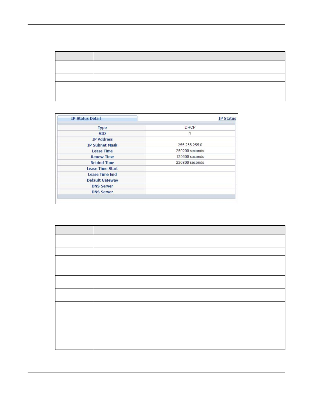
Chapter 8 Basic Setting
The following table describes the labels in this screen.
Table 16 Basic Setting > IP Setup > IP Status Details: Static
LABEL DESCRIPTION
T ype This shows whether ths IP address is dynamically assigned from a DHCP server or manually
VID This is the VLAN identification number to which an IP routing domain belongs.
IP Address This is the IP address of your Switch in dotted decimal notation for example 192.168.1.1.
IP Subnet Mask This is the IP subnet mask of your Switch in dotted decimal notation for example
assigned (Static or DHCP).
255.255.255.0.
Figure 64 Basic Setting > IP Setup > IP Status Details: DHCP
The following table describes the labels in this screen.
Table 17 Basic Setting > IP Setup > IP Status Details: DHCP
LABEL DESCRIPTION
T ype This shows whether ths IP address is dynamically assigned from a DHCP server or manually
VID This is the VLAN identification number to which an IP routing domain belongs.
IP Address This is the IP address of your Switch in dotted decimal notation for example 192.168.1.1.
IP Subnet Mask This is the IP subnet mask of your Switch in dotted decimal notation for example
Lease Time This displays the length of time in seconds that this interface can use the current dynamic
Renew Time This displays the le ngth of time from the lease s tart that the Switch wil l request to renew its
Rebind Time This displays the length of time from the lease start that the Switch will request to get any
Lease Time
Start
Lease Time End This displays the date and time that the current dynamic IP address assignment from the
assigned (Static or DHCP).
255.255.255.0.
IP address from the DHCP server.
current dynamic IP address from the DHCP server.
dynamic IP address from the DHCP server.
This displays the date and time that the current dynamic IP address assignment from the
DHCP server began. You should configure date and time in Basic Setting > General
Setup.
DHCP server will end. You should configure date and time in Basic Setting > General
Setup.
GS2210/XGS2210 Series User’s Guide
75
Page 76
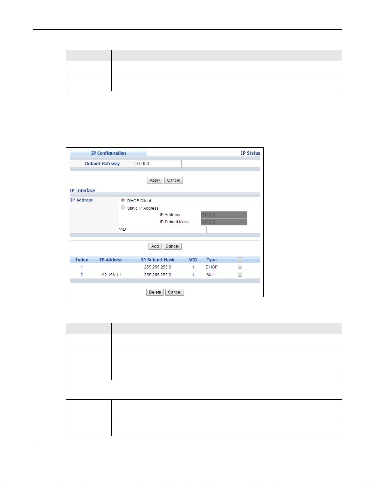
Table 17 Basic Setting > IP Setup > IP Status Details: DHCP (continued)
LABEL DESCRIPTION
Default Gateway This displays the IP address of the default gateway assigned by the DHCP server. 0.0.0.0
means no gateway is assigned.
DNS Server This displays the IP address of the primary and secondary DNS servers assigned by the
DHCP server. 0.0.0.0 means no DNS server is assigned.
8.6.3 IP Configuration
Use this screen to configure the default gateway device, the default domain name server and add IP
domains.
Figure 65 Basic Setting > IP Setup > IP Configuration
Chapter 8 Basic Setting
The following table describes the labels in this screen.
Table 18 Basic Setting > IP Setup > IP Configuration
LABEL DESCRIPTION
Default Gateway Type the IP address of the default outgoing gateway in dotted decimal notation, for
example 192.168.1.254.
Apply Click Apply to save your changes to the Switch’s run-time memory. The Switch loses thes e
Cancel Click Cancel to reset the fields to your previous configuration.
IP Interface
Use these fields to create or edit IP routing domains on the Switch.
DHCP Client Select this option if you have a DHCP server that can assign the Switch an IP address,
Static IP
Address
changes if it is turned off or loses power, so use the Save link on the top navigation panel
to save your changes to the non-volatile memory when you are done configuring.
subnet mask, a default gateway IP address and a domain name server IP address
automatically.
Select this option if you don’t have a DHCP server or if you wish to assign static IP address
information to the Switch. You need to fill in the following fields when you select this option.
GS2210/XGS2210 Series User’s Guide
76
Page 77

Chapter 8 Basic Setting
Table 18 Basic Setting > IP Setup > IP Configuration (continued)
LABEL DESCRIPTION
IP Address Enter the IP address of your Switch in dotted decimal notation, for example, 192.168.1.1.
This is the IP address of the Switch in an IP routing domain.
IP Subnet
Mask
VID Ent er the VLAN identification number to which an IP routing domain belongs.
Add Click this to create a new entry.
Cancel Click Cancel to reset the fields to your previous configuration.
Index This field displays the index number of an entry.
IP Address This field displays IP address of the Switch in the IP domain.
IP Subnet Mask This field displays the subnet mask of the Switch in the IP domain.
VID This field displays the VLAN identification number of the IP domain on the Switch.
Type This field displays the type of IP address status.
Delete Click Delete to remove the selected entry from the summary table.
Enter the IP subnet mask of an IP routing domain in dotted decimal notation, for example,
255.255.255.0.
This saves your changes to the Switch’s run-time memory. The Switch loses these changes
if it is turned off or loses power, so use the Save link on the top navigation panel to save
your changes to the non-volatile memory when you are done configuring.
Select an entry’s check box t o select a specific en try. Otherwise, select the check box in the
table heading row to select all entries.
Cancel Click Cancel to clear the check boxes.
8.7 Port Setup
Use this screen to configure Switch port settings. Click Basic Setting > Port Setup in the
navigation panel to display the configuration screen.
Note: Deleting all IP subnets locks you out of the Switch.
GS2210/XGS2210 Series User’s Guide
77
Page 78
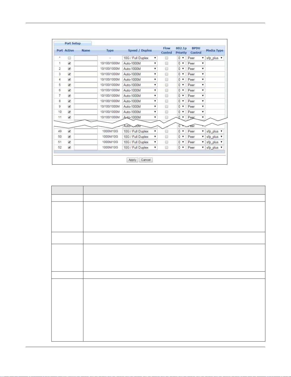
Chapter 8 Basic Setting
Figure 66 Basic Setting > Port Setup
The following table describes the labels in this screen.
Table 19 Basic Setting > Port Setup
LABEL DESCRIPTION
Port This is the port index number.
* Settings in this row apply to all ports.
Use this row only if you want to make some settings the same for all ports. Use this row first
to set the common settings and then make adjustments on a port-by-port basis.
Note: Changes in this row are copied to all the ports as soon as you make them.
Active Select this check box to enable a port. The factory default for all ports is enabled. A port
must be enabled for data transmission to occur.
Name Enter a descriptive name that identifies this port. You can enter up to 64 alpha-numerical
characters.
Note: Due to space limitation, the port name may be truncated in some web configurator
screens.
Type This field displays the capacity that the port can support.
Speed/Duplex Select the speed and the duplex mode of the Ethernet connection on this port. Choices are
Auto-1000M, 10M/Half Duplex, 10M/Full Duplex, 100M/Half Duplex, 100M/Full
Duplex and 1000M/Full Duplex (Gigabit connections only).
Selecting Auto-1000M (auto-negotiation) allows one port to negotiate with a peer port
automatically to obtain the connection speed (of up to 1000M) and duplex mode that both
ends support. When auto-negotiation is turned on, a port on the Switch negotiates with the
peer automatically to determine the connection speed and duplex mode. If the peer port
does not support auto-negotiation or turn s off this feature, the Switch determines the
connection speed by detecting the signal on the cable and using half duplex mode. When the
Switch’s auto-negotiation is turned off, a port uses the pre-configured speed and duplex
mode when making a connection, thus requiring you to make sure that the settings of the
peer port are the same in order to connect.
GS2210/XGS2210 Series User’s Guide
78
Page 79

Chapter 8 Basic Setting
Table 19 Basic Setting > Port Setup (continued)
LABEL DESCRIPTION
Flow Control A concentration of traffic on a port decreases port bandwidth and overflows buffer memory
causing packet discards and frame losses. Flow Control is used to regulate transmission of
signals to match the bandwidth of the receiving port.
The Switch uses IEEE802.3x flow control in full duplex mode and backpressure flow control in
half duplex mode.
IEEE802.3x flow control is used in full duplex mode to send a pause signal to the sending
port, causing it to temporarily stop sending signals when the receiving port memory buffers
fill.
Back Pressure flow control is typically used in half duplex mode to send a "collision" signal to
the sending port (mimicking a state of packet collision) causing the sending port to
temporarily stop sending signals and resend later. Select Flow Control to enable it.
802.1p
Priority
BPDU Control Configure the way to treat BPDUs received on this port. You must activate bridging control
Media Type On the Switch that has a 10 Gigabit interface, such as the SFP+ slot, you can insert either an
Apply Click Apply to save your changes to t he Switch’s run-time memory. The Switch loses these
Cancel Click Cancel to begin configuring this screen afresh.
This priority value is added to incoming frames without a (802.1p) priority queue tag. See
Priority Queue Assignment in Table 14 on page 72 for more information.
protocol transparency in the Switch Setup screen first.
Select Peer to process any BPDU (Bridge Protocol Data Units) received on this port.
Select Tunnel to forward BPDUs received on this port.
Select Discard to drop any BPDU received on this port.
Select Network to process a BPDU with no VLAN tag and forward a tagged BPDU.
SFP+ transceiver or an SFP+ Direct Attach Copper (DAC). An SFP+ Direct Attach Copper
(DAC) is an SFP+ housing that has no optical module but uses a fixed-length passive copper
cable assembly, which reduces cost and power significantly.
Select the media type (sfp_plus or dac10g) of the SFP+ module that is attached to the 10
Gigabit interface.
changes if it is turned off or loses power , so use the Save link on the top navigation panel to
save your changes to the non-volatile memory when you are done configuring.
8.8 PoE Status
Note: The following screens are available for the PoE model(s) only. Some features are
only available for the Ethernet ports (1 to 8 for GS2210-8HP, 1 to 24 for GS221024HP, 1 to 48 for GS2210-48HP, 1 to 24 for XGS2210-28HP and 1 to 48 for
XGS2210-52HP).
The PoE model(s) supports the IEEE 802.3at High Power over Ethernet (PoE) standard.
A powered device (PD) is a device such as an access point or a switch, that supports PoE (Power
over Ethernet) so that it can receive power from another device through an Ethernet port.
In the figure below, the IP camera and IP phone get their power directly from the Switch. Aside
from minimizing the need for cables and wires, PoE removes the hassle of trying to find a nearby
electric outlet to power up devices.
GS2210/XGS2210 Series User’s Guide
79
Page 80

Chapter 8 Basic Setting
Figure 67 Powered Device Examples
You can also set priorities so that the Switch is able to reserve and allocate power to certain PDs.
Note: The POE (Power over Ethernet) devices that supply or receive power and their
connected Ethernet cables must all be completely indoors.
To view the current amount of power that PDs are receiving from the Switch, click Basic Setting >
PoE Setup.
Figure 68 Basic Setting > PoE Status
GS2210/XGS2210 Series User’s Guide
80
Page 81

Chapter 8 Basic Setting
The following table describes the labels in this screen.
Table 20 Basic Setting > PoE Status
LABEL DESCRIPTION
PoE Status
PoE Mode This field displays the power management mode used by the Switch, whether it is in
Total Power (W) This field displays the total power the Switch can provide to the connected PoE-enabled
Consuming
Power (W)
Allocated Power
(W)
Remaining
Power (W)
Classification or Consumption mode.
devices on the PoE ports.
This field displays the amount of power the Switch is currently supplying to the connected
PoE-enabled devices.
This field displays the total amount of power the Switch has reserved for PoE after
negotiating with the connected PoE device(s).
Consuming Power (W) can be less than or equal but not more than the Allocated Power
(W).
This field displays the amount of power the Switch can still provide for PoE.
Note: The Switch must have at least 16 W of remaining power in order to supply power to a
PoE device, even if the PoE device needs less than 16W.
Port This is the port index number.
State This field shows which ports can receive power from the Switch. You can set this in Section
8.8.2 on page 82.
• Disable - The PD connected to this port cannot get power supply.
• Enable - The PD connected to this port can receive power.
Class This shows the power classification of the PD.
This is a number from 0 to 4, where each value represents a range of power (W) and power
current (mA) that the PD requires to function. The ranges are as follows.
• Class 0 - Default, 0.44 to 12.94
• Class 1 - Optional, 0.44 to 3.84
• Class 2 - Optional, 3.84 to 6.49
• Class 3 - Optional, 6.49 to 12.95
• Class 4 - Reserved (PSEs classify as Class 0) in a Switch that supports IEEE 802.3af
only. Optional, 12.95 to 25.50 in a Switch that supports IEEE 802.3at.
PD Priority When the total power requested by the PDs exceeds the total PoE power budget on the
Switch, you can set the PD priority to allow the Switch to provide power to ports with higher
priority first.
• Critical has the highest priority.
• High has the Switch assign power to the port after all critical priority ports are served.
• Low has the Switch assign power to the port after all critical and high priority ports are
served.
Power-Up This field displays the PoE standard the Switch uses to provide power on this port.
Consuming
Power (mW)
Max Power
(mW)
This field displays the current amount of power consumed by the PD from the Switch on this
port.
This field displays the maximum amount of power the PD could use from the Switch on this
port.
8.8.1 PoE Time Range Status
Use this screen to see whether PoE is scheduled to be enabled on a port.
GS2210/XGS2210 Series User’s Guide
81
Page 82
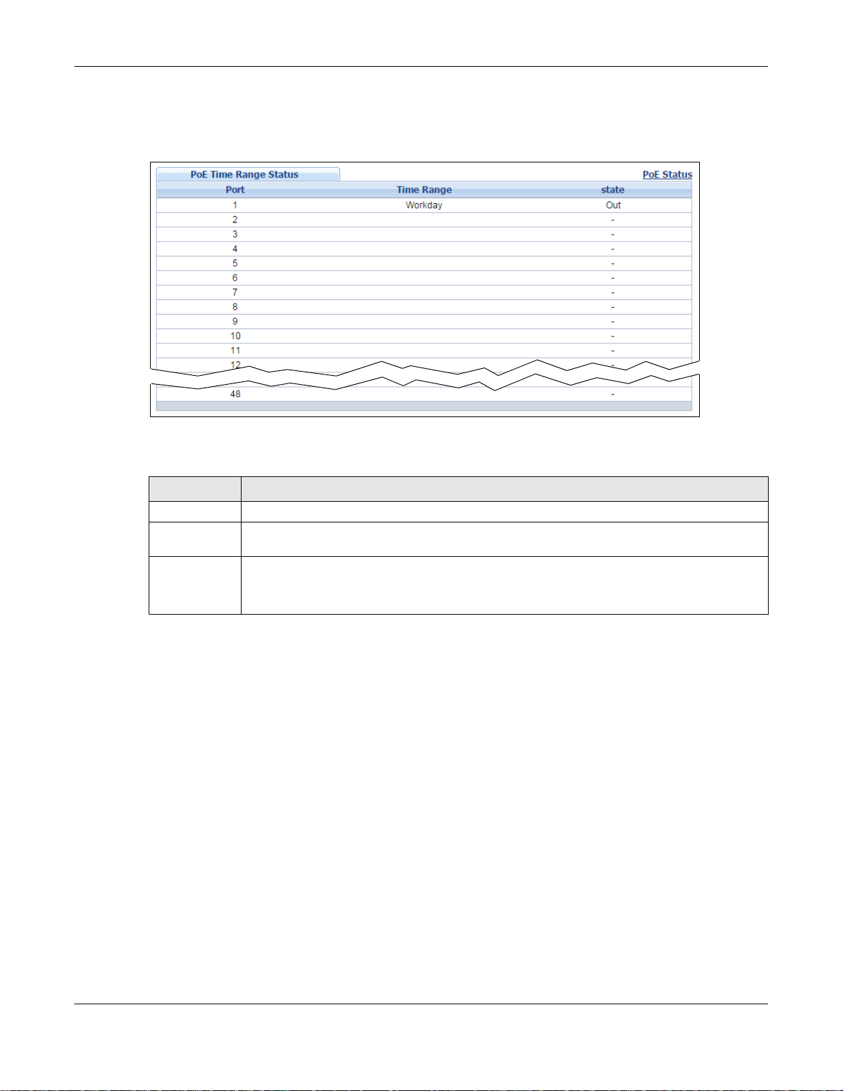
Chapter 8 Basic Setting
Click the PoE Time Range Status link in the Basic Setting > PoE Status screen. The following
screen opens.
Figure 69 Basic Setting > PoE Setup > PoE Time Range Status
The following table describes the labels in this screen.
Table 21 Basic Setting > PoE Setup > PoE Time Range Status
LABEL DESCRIPTION
Port This is the number of the port on the Switch.
Time Range This field displays the name of the schedule which is applied to the port. PoE is enabled at the
state This field displays whether the port can receive power from the Switch (In) or not (Out)
8.8.2 PoE Setup
Use this screen to set the priority levels, power-up mode and schedule for the Switch in distributing
power to PDs.
Click the PoE Setup link in the Basic Setting > PoE Status screen. The following screen opens.
specified time/date.
currently.
It shows - if there is no schedule applied to the port.
GS2210/XGS2210 Series User’s Guide
82
Page 83

Chapter 8 Basic Setting
Figure 70 Basic Setting > PoE Setup
The following table describes the labels in this screen.
Table 22 Basic Setting > PoE Setup
LABEL DESCRIPTION
PoE Mode Select the power management mode you want the Switch to use.
• Classification - Select this if you want the Switch to reserve the Max Power (mW) to
each PD according to the priority level. If the total power supply runs out, PDs with lower
priority do not get power to function.
• Consumption - Select this if you want the Switch to manage the tota l power supply so
that each connected PD gets a resource. However, the power allocated by the Switch ma y
be less than the Max Power (mW) of the PD. PDs with higher priority also get more power
than those with lower priority levels.
Pre-Allocate Select this to have the Switch pre-allocate power to each port based on the classification of
the PD device.
Dual Detection Select this to have the Switch run another detecting procedure between the detection and
classification stages. This helps check if the power interface (PI) range of the connected PD is
within the IEEE 802.3AF/AT standard range and ensures it is an IEEE PD.
Power U p
Sequence
Delay
Port This is the port index number.
Select this to allow PoE ports to be powered up one-by-one randomly or clear to allow them
all to be powered up at the same time.
GS2210/XGS2210 Series User’s Guide
83
Page 84

Chapter 8 Basic Setting
Table 22 Basic Setting > PoE Setup (continued)
LABEL DESCRIPTION
* Settings in this row apply to all ports.
Use this row only if you want to make some settings the same for all ports. Use this row first
to set the common settings and then make adjustments on a port-by-port basis.
Note: Changes in this row are copied to all the ports as soon as you make them.
PD Select this to provide power to a PD connected to the port.
If left unchecked, the PD connected to the port cannot receive power from the Switch.
PD Priority When the total power requested by the PDs exceeds the total PoE power budget on the
Switch, you can set the PD priority to allow the Switch to provide power to ports with higher
priority.
Select Critical to give the highest PD priority on the port.
Select High to set the Switch to assign the remaining power to the port after all critical
priority ports are served.
Select Low to set the Switch to assign the remaining power to the port after all critical and
high priority ports are served.
Power-Up Set how the Switch provides power to a connected PD at power-up.
802.3af - the Switch follows the IEEE 802.3af Powe r over Ethernet standard to supply power
to the connected PDs during power-up.
Legacy - the Switch can provide power to the connected PDs that require high inrush
currents at power-up. Inrush cur ren t is the maxim um, i nst antane ous i nput cu rrent dr a wn by
the PD when first turned on.
Pre-802.3at - the Switch initially offers power on the port according to the IEEE 802.3af
standard, and then switches to support the IEEE 802.3at standard within 75 milliseconds
after a PD is connected to the port. Select this option if the Switch is performing 2-event
Layer-1 classification (PoE+ hardware classification) or the connected PD is NOT performing
Layer 2 power classification using Link Layer Discovery Protocol (LLDP).
802.3at - the Switch supports the IEEE 802.3at High Power over Ethernet standard and can
supply power of up to 30W per Ethernet port. IEEE 802.3at is also known as PoE+ or PoE
Plus. An IEEE 802.3at compatible device is referred to as Type 2. Power Class 4 (High Power)
can only be used by T y pe 2 devices. If the connected PD requires a Class 4 current when i t is
turned on, it will be powered up in this mode.
Max Power
(mW)
Wide Range
Detection
Time Range Select a pre-defined schedule (created using the Advanced Application > Time Range
Apply Click Apply to save your changes to t he Switch’s run-time memory. The Switch loses these
Cancel Click Cancel to begin configuring this screen afresh.
Specify the maximum amount of power the PD could use from the Switch on this port.
Select this to let the Switch have a wider detection range for the PD.
The Switch detects whether a connected device is a powered device or not before supplying
power to the port. For the PD detection, the Switch applies a fixed voltage to the device and
then receives returned current. If the returned current is within the IEEE 802.3AF/AT
standard range, the device will be considered as a valid PD by the Switch.
However, in real cases, environmental interferences might easily cause the returned current
to be out of the standard range.
screen) to control when the Switch enables PoE to provide power on the port.
If you leave this field blank, PoE is disabled on the port.
changes if it is turned off or loses power , so use the Save link on the top navigation panel to
save your changes to the non-volatile memory when you are done configuring.
GS2210/XGS2210 Series User’s Guide
84
Page 85
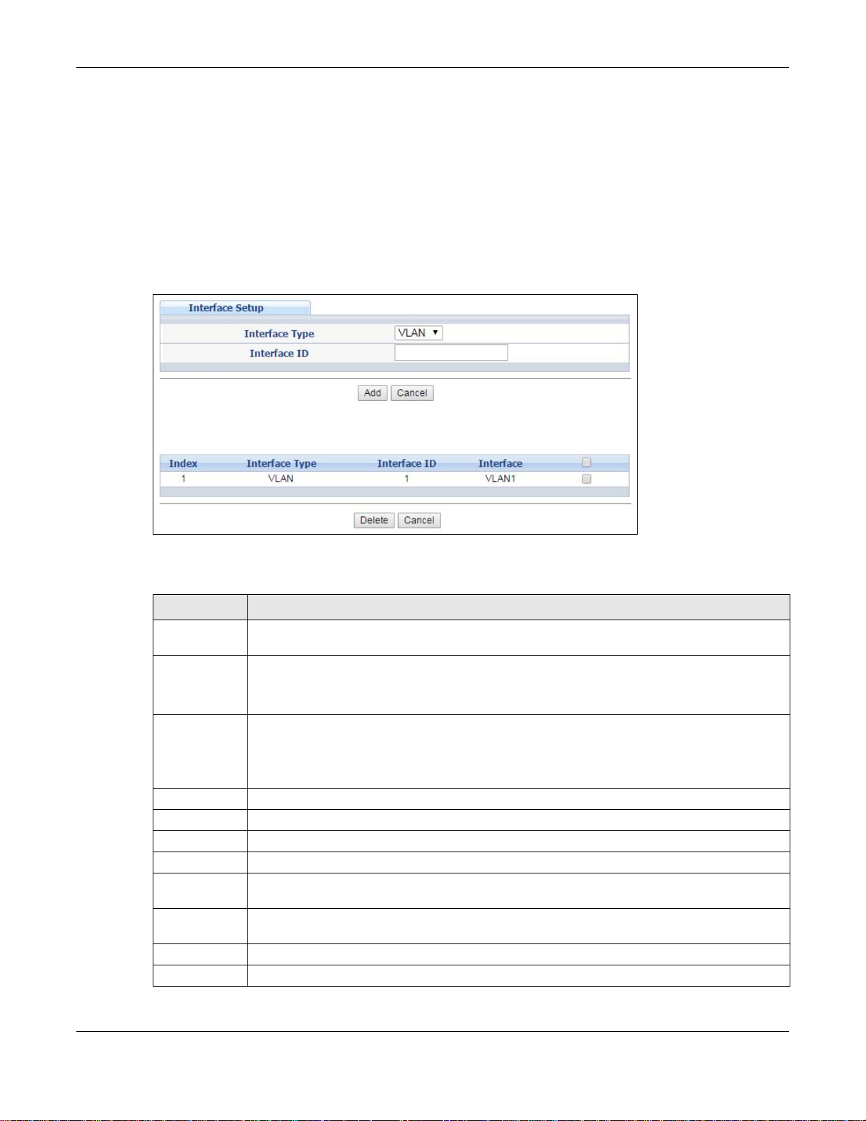
8.9 Interface Setup
An IPv6 address is configured on a per-interface basis. The interface can be a physical interface (for
example, an Ethernet port) or a virtual interface (for example, a VLAN). The Switch supports the
VLAN interface type for IPv6 at the time of writing.
Use this screen to set IPv6 interfaces on which you can configure an IPv6 address to access and
manage the Switch. Click Basic Setting > Interface Setup in the navigation panel to display the
configuration screen.
Figure 71 Basic Setting > Interface Setup
Chapter 8 Basic Setting
The following table describes the labels in this screen.
Table 23 Basic Setting > Interface Setup
LABEL DESCRIPTION
Interface Type Select the type of IPv6 interface for which you want to configure. The Switch supports the
VLAN interface type for IPv6 at the time of writing.
Interface ID Specify a unique identification number (from 1 to 4094) for the interface.
To have IPv6 function properly, you should configure a static VLAN with the same ID number
in the Advanced Application > VLAN screens.
Add Click this to create a new entry.
This saves your changes to the Switch’s run-time memory. The Switch loses these changes if
it is turned off or loses power, so use the Save link on the top navigation panel to save your
changes to the non-volatile memory when you are done configuring.
Cancel Click Cancel to reset the fields to your previous configuration.
Index This field displays the index number of an entry.
Interface Type This field displays the type of interface.
Interface ID This field displays the identification number of the interface.
Interface This field displays the interface’s descriptive name which is generated automatically by the
Switch. The name is from a combination of the interface type and ID number.
Select an entry’s check box to select a specific entry. Otherwise, select the check box in the
table heading row to select all entries.
Delete Click Delete to remove the selected entry from the summary table.
Cancel Click Cancel to clear the check boxes.
GS2210/XGS2210 Series User’s Guide
85
Page 86
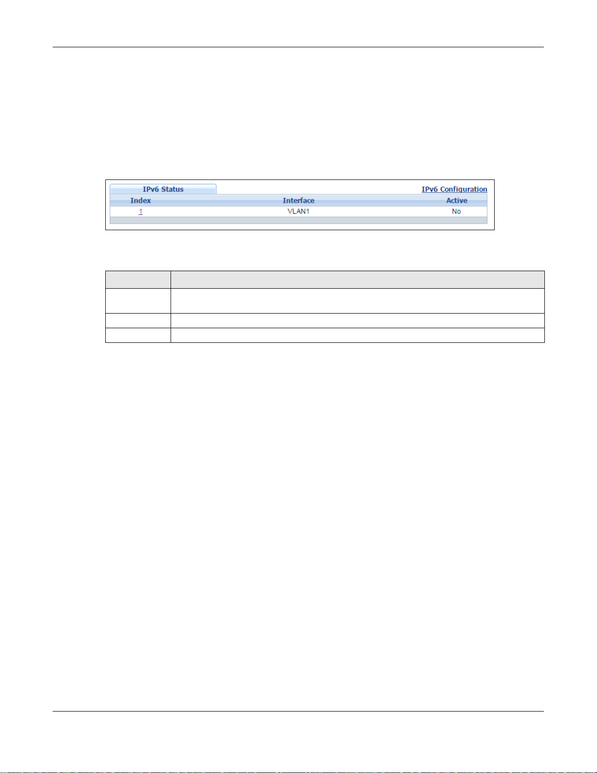
8.10 IPv6
Use this screen to view the IPv6 interface status and configure Switch’s management IPv6
addresses.
Click Basic Setting > IPv6 in the navigation panel to display the IPv6 status screen as shown
next.
Figure 72 Basic Setting > IPv6
The following table describes the labels in this screen.
Table 24 Basic Setting > IPv6
LABEL DESCRIPTION
Index This field displays the index number of an IPv6 interface. Click on an index number to view
Interface This is the name of the IPv6 interface you created.
Active This field displays whether the IPv6 interface is activated or not.
Chapter 8 Basic Setting
more interface details.
8.10.1 IPv6 Interface Status
Use this screen to view a specific IPv6 interface status and detailed information. Click an interface
index number in the Basic Setting > IPv6 screen. The following screen opens.
GS2210/XGS2210 Series User’s Guide
86
Page 87
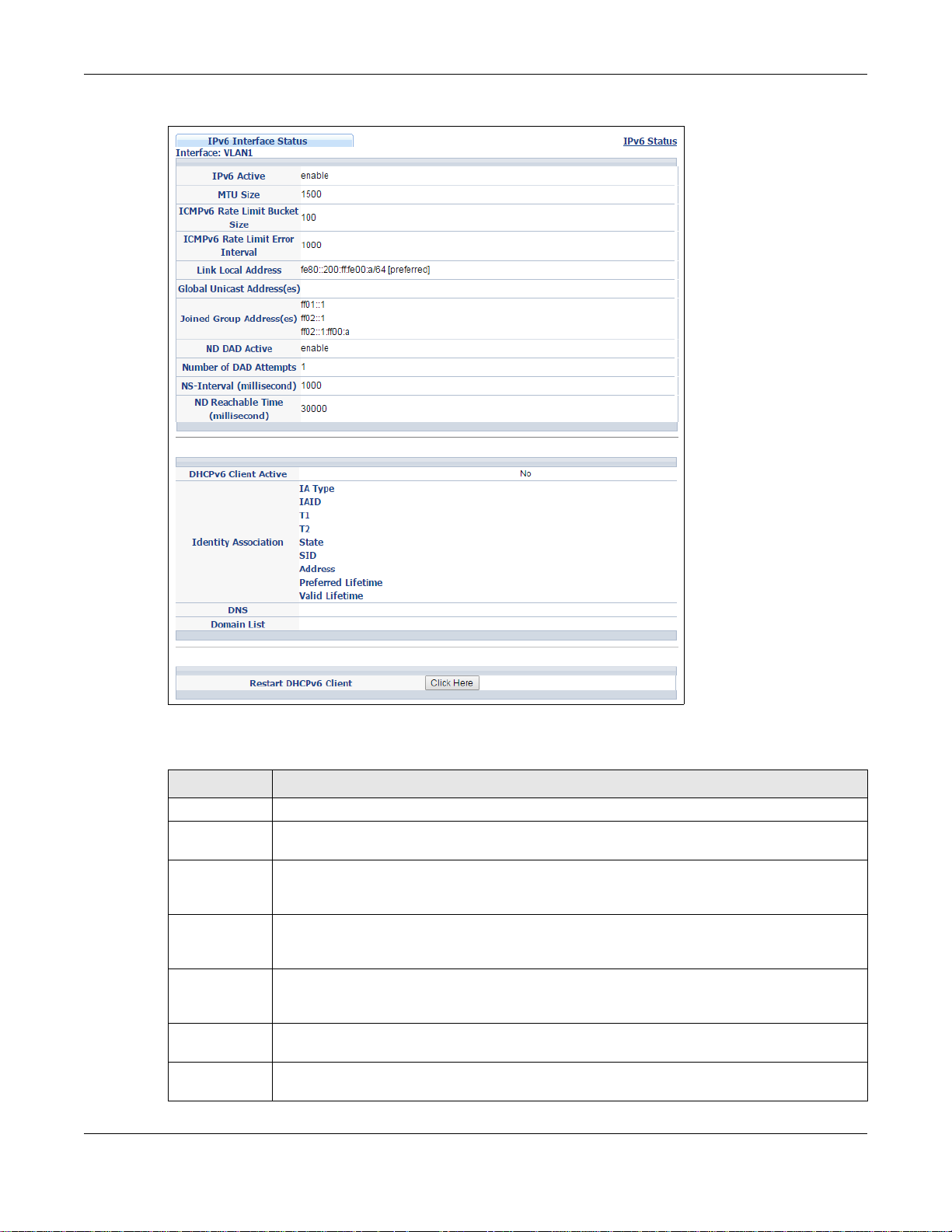
Chapter 8 Basic Setting
Figure 73 Basic Setting > IPv6 > IPv6 Interface Status
The following table describes the labels in this screen.
Table 25 Basic Setting > IPv6 > IPv6 Interface Status
LABEL DESCRIPTION
IPv6 Active This field displays whether the IPv6 interface is activated or not.
MTU Size This field displays the Maximum Transmission Unit (MTU) size for IPv6 packets on this
interface.
ICMPv6 Rate
Limit Bucket
Size
ICMPv6 Rate
Limit Error
Interval
Link Local
Address
Global Unicast
Address(es)
Joined Group
Address(es)
This field displays the maximum number of ICMPv6 error messages which are allowed to
transmit in a given time interval. If the bucket is full, subsequent error messages are
suppressed.
This field displays the time period (in milliseconds) during which ICMPv6 error messages of
up to the bucket size can be transmitted. 0 means no limit.
This field displays the Switch’s link-local IP address and prefix generated by the interface. It
also shows whether the IP address is preferred, which means it is a valid address and can be
used as a sender or receiver address.
This field displays the Switch’s global unicast address to identify this interface.
This field displays the IPv6 multicast addresses of groups the Switch’s interface joins.
GS2210/XGS2210 Series User’s Guide
87
Page 88

Chapter 8 Basic Setting
Table 25 Basic Setting > IPv6 > IPv6 Interface Status (continued)
LABEL DESCRIPTION
ND DAD
Active
Number of
DAD Attempts
NS-Interval
(millisecond)
ND Reachable
Time
(millisecond)
DHCPv6 Client
Active
Identity
Association
IA Type The IA type is the type of address in the IA. Each IA holds one type of address. IA_NA
IAID Each IA consists of a unique IAID and associated IP information.
T1 This field displays the DHCPv6 T1 timer. After T1, the Switch sends the DHCPv6 server a
T2 This field displays the DHCPv6 T2 timer. If the time T2 is reached and the server does not
State This field displays the state of the TA. It shows
This field displays whether Neighbor Discovery (ND) Duplicate Address Detection (DAD) is
enabled on the interface.
This field displays the number of consecutive neighbor solicitations the Switch sends for this
interface.
This field displays the time interval (in m illiseconds) at which neighbor solicitations are re-
sent for this interface.
This field displays how long (in milliseconds) a neighbor is considered reachable for this
interface.
This field displays whether the Switch acts as a DHCPv6 client to get an IPv6 address from a
DHCPv6 server.
An Identity Association (IA) is a collection of addresses assigned to a DHCP client, through
which the server and client can manage a set of related IP addresses. Each IA must be
associated with exactly one interface.
means an identity association for non-temporary addresses and IA_TA is an identity
association for temporary addresses.
Renew message.
An IA_NA option contains the T1 and T2 fields, but an IA_TA option does not. The DHCPv6
server uses T1 and T2 to control the time at which the client contacts with the server to
extend the lifetimes on any addresses in the IA_NA before the lifetimes expire.
respond, the Switch sends a Rebind message to any available server.
Active when the Switch obtains addresses from a DHCpv6 server and the TA is created.
Renew when the TA’s address lifetime expires and the Switch sends out a Renew message.
Rebind when the Switch doesn’t receive a response from the original DHCPv6 server and
sends out a Rebind message to another DHCPv6 server.
SID This field displays the DHCPv6 server’s unique ID.
Address This field displays the Switch’s global address which is assigned by the DHCPv6 server.
Preferred
Lifetime
Valid
Lifetime
DNS This field displays the DNS server address assigned by the DHCPv6 server.
Domain List This field displays the address record when the Switch queries the DNS server to resolve
Restart
DHCPv6 Client
This field displays how long (in seconds) that the global address remains preferred.
This field displays how long (in seconds) that the global address is valid.
domain names.
Click Click Here to send a new DHCP request to the DHCPv6 server and update the IPv6
address and DNS information for this interface.
8.10.2 IPv6 Configuration
Use this screen to configure IPv6 settings on the Switch. Click the IPv6 Configuration link in the
Basic Setting > IPv6 screen. The following screen opens.
GS2210/XGS2210 Series User’s Guide
88
Page 89
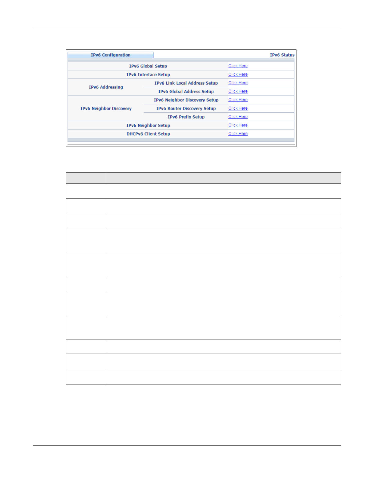
Chapter 8 Basic Setting
Figure 74 Basic Setting > IPv6 > IPv6 Configuration
The following table describes the labels in this screen.
Table 26 Basic Setting > IPv6 > IPv6 Configuration
LABEL DESCRIPTION
IPv6 Global
Setup
IPv6 Interface
Setup
IPv6
Addressing
IPv6 Link-
Local
Address
Setup
IPv6
Global
Address
Setup
IPv6 Neighbor
Discovery
IPv6
Neighbor
Discovery
Setup
IPv6
Router
Discovery
Setup
IPv6 Prefix
Setup
IPv6 Neighbor
Setup
DHCPv6 Client
Setup
Click the link to go to a screen where you can configure the global IPv6 settings on the
Switch.
Click the link to go to a screen where you can enable an IPv6 interface on the Switch.
Click the link to go to a screen where you can configure the IPv6 link-local address for an
interface.
Click the link to go to a screen where you can configure the IPv6 global address for an
interface.
Click the link to go to a screen where you can configure the IPv6 neighbor discovery settings.
Click the link to go to a screen where you can configure the IPv6 router discovery settings.
Click the link to go to a screen where you can configure the Switch’s IPv6 prefix list.
Click the link to go to a screen where you can create a static IPv6 neighbor entry in the
Switch’s IPv6 neighbor table.
Click the link to go to a screen where you can configure the Switch DHCP settings.
8.10.3 IPv6 Global Setup
Use this screen to configure the global IPv6 settings. Click the link next to IPv6 Global Setup in
the IPv6 Configuration screen to display the screen as shown next.
GS2210/XGS2210 Series User’s Guide
89
Page 90
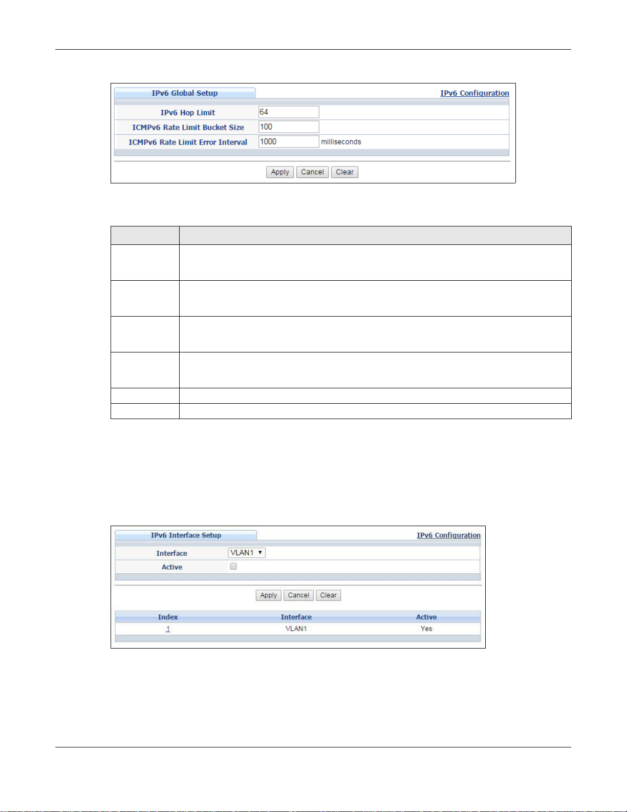
Chapter 8 Basic Setting
Figure 75 Basic Setting > IPv6 > IPv6 Configuration > IPv6 Global Setup
The following table describes the labels in this screen.
Table 27 Basic Setting > IPv6 > IPv6 Configuration > IPv6 Global Setup
LABEL DESCRIPTION
IPv6 Hop Limit Specify the maximum number of hops (from 1 to 255) in router advertisements. This is the
maximum number of hops on which an IPv6 packet is allowed to transmit before it is
discarded by an IPv6 router, which is similar to the TTL field in IPv4.
ICMPv6 Rate
Limit Bucket
Size
ICMPv6 Rate
Limit Error
Interval
Apply Click Apply to save your changes to t he Switch’s run-time memory. The Switch loses these
Cancel Click Cancel to begin configuring this screen afresh .
Clear Click Clear to reset the fields to the factory defaults.
Specify the maximum number of ICMPv6 error messages (from 1 to 200) which are allowed
to transmit in a given time interval. If the bucket is full, subsequent error messages are
suppressed.
Specify the time period (from 0 to 2147483647 milliseconds) during which ICMPv6 error
messages of up to the bucket size can be transmitted. 0 means no limit.
changes if it is turned off or loses power , so use the Save link on the top navigation panel to
save your changes to the nonvolatile memory when you are done configuring.
8.10.4 IPv6 Interface Setup
Use this screen to turn on or off an IPv6 interface and enable stateless autoconfiguration on it. Click
the link next to IPv6 Interface Setup in the IPv6 Configuration screen to display the screen as
shown next.
Figure 76 Basic Setting > IPv6 > IPv6 Configuration > IPv6 Interface Setup
GS2210/XGS2210 Series User’s Guide
90
Page 91
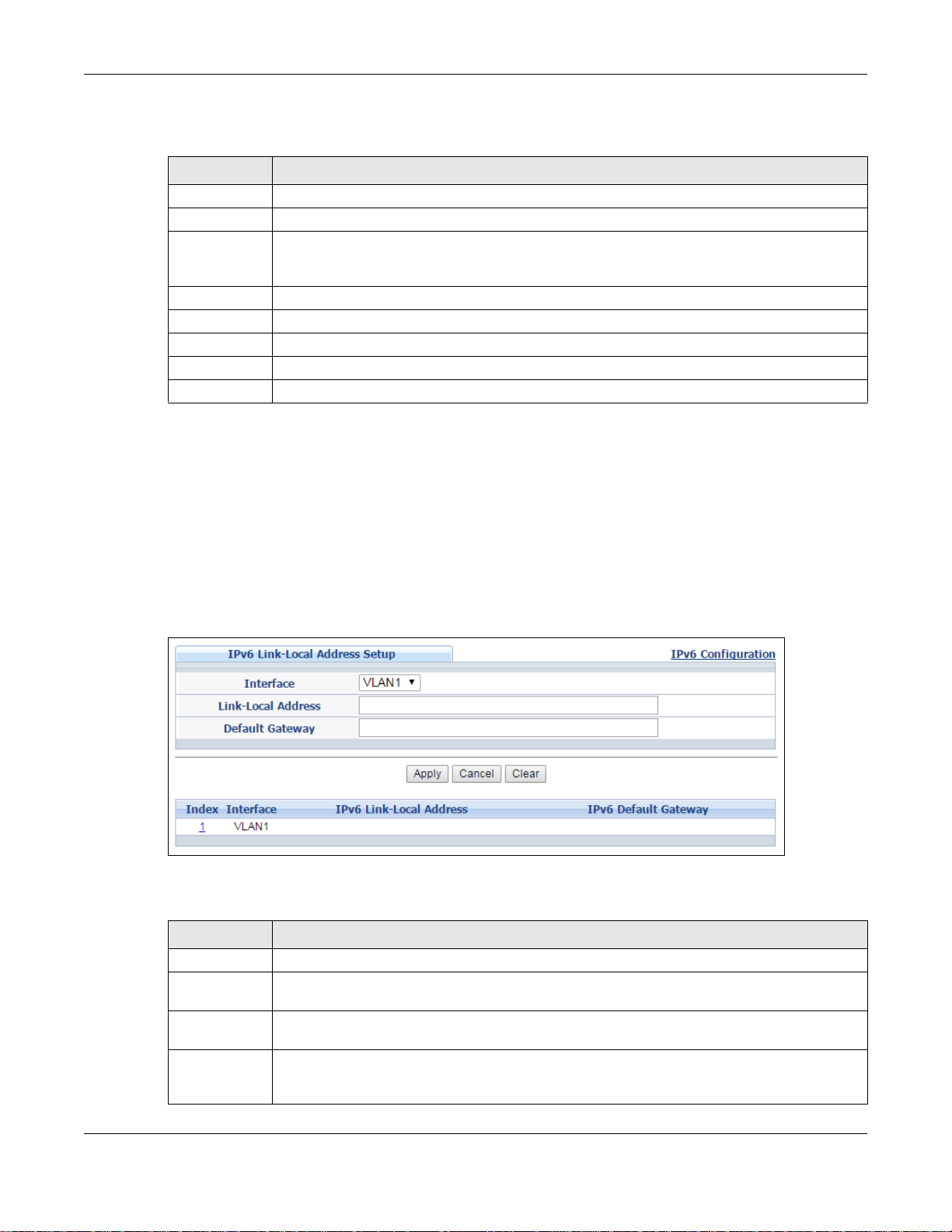
Chapter 8 Basic Setting
The following table describes the labels in this screen.
Table 28 Basic Setting > IPv6 > IPv6 Configuration > IPv6 Interface Setup
LABEL DESCRIPTION
Interface Select the IPv6 interface you want to configure.
Active Select this option to enable the interface.
Apply Click Apply to save your changes to t he Switch’s run-time memory. The Switch loses these
Cancel Click Cancel to begin configuring this screen afresh .
Clear Click Clear to reset the fields to the factory defaults.
Index This is the interface index number. Click on an index number to change the settings.
Interface This is the name of the IPv6 interface you created.
Active This field displays whether the IPv6 interface is activated or not.
changes if it is turned off or loses power , so use the Save link on the top navigation panel to
save your changes to the nonvolatile memory when you are done configuring.
8.10.5 IPv6 Link-Local Address Setup
A link-local address uniquely identifies a device on the local network (the LAN). It is similar to a
“private IP address” in IPv4. You can have the same link-local address on multiple interfaces on a
device. A link-local unicast address has a predefined prefix of fe80::/10.
Use this screen to configure the interface’s link-local address and default gateway. Click the link
next to IPv6 Link-Local Address Setup in the IPv6 Configuration screen to display the screen
as shown next.
Figure 77 Basic Setting > IPv6 > IPv6 Configuration > IPv6 Link-Local Address Setup
The following table describes the labels in this screen.
Table 29 Basic Setting > IPv6 > IPv6 Configuration > IPv6 Link-Local Address Setup
LABEL DESCRIPTION
Interface Select the IPv6 interface you want to configure.
Link-Local
Address
Default
Gateway
Apply Click Apply to save your changes to t he Switch’s run-time memory. The Switch loses these
Manually configure a static IPv6 link-local address for the interface.
Set the default gateway IPv6 address for the interface. When an interface cannot find a
routing information for a frame’s destination, it forwards the packet to the default gateway.
changes if it is turned off or loses power , so use the Save link on the top navigation panel to
save your changes to the nonvolatile memory when you are done configuring.
GS2210/XGS2210 Series User’s Guide
91
Page 92
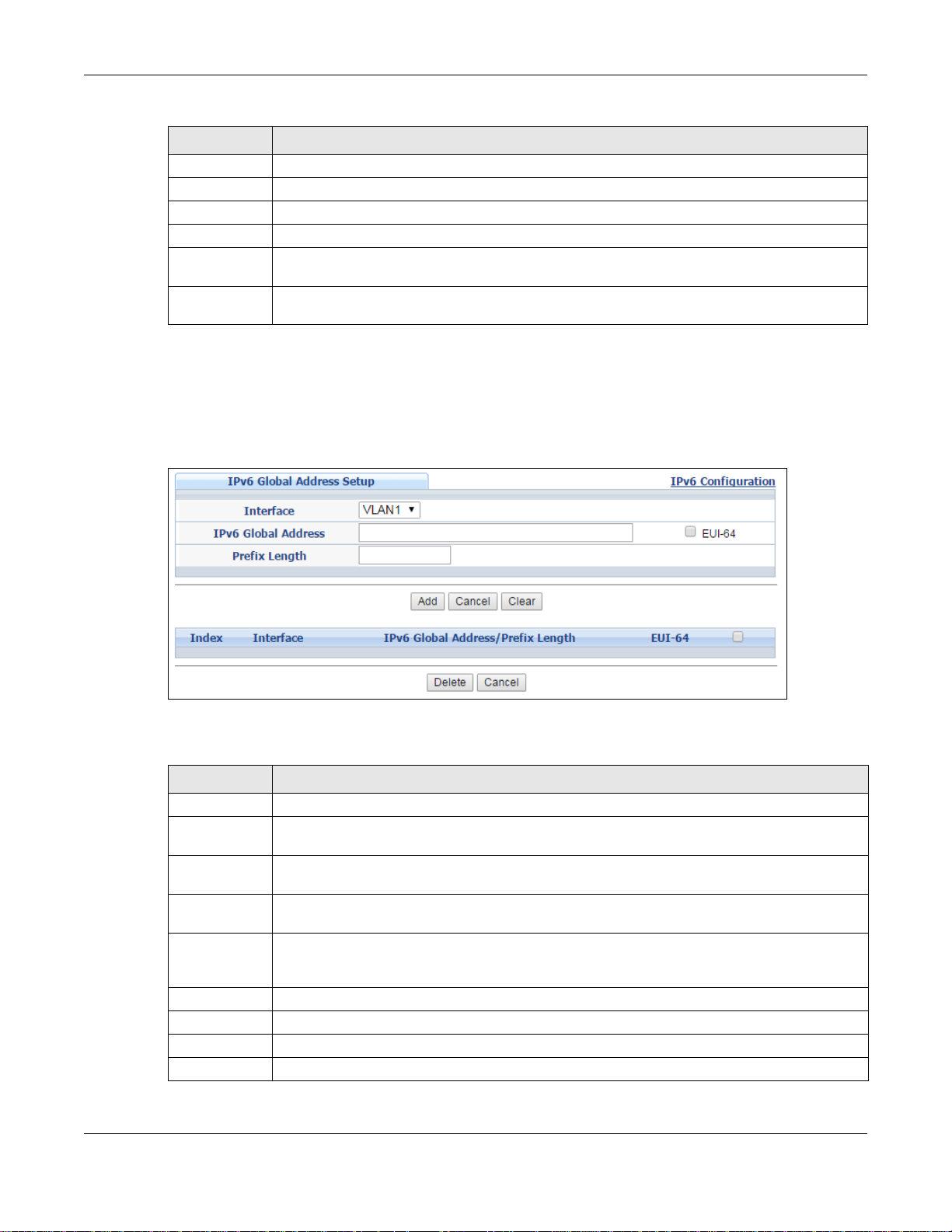
Chapter 8 Basic Setting
Table 29 Basic Setting > IPv6 > IPv6 Configuration > IPv6 Link-Local Address Setup (continued)
LABEL DESCRIPTION
Cancel Click Cancel to begin configuring this screen afresh .
Clear Click Clear to reset the fields to the factory defaults.
Index This is the interface index number. Click on an index number to change the settings.
Interface This is the name of the IPv6 interface you created.
IPv6 Link-
Local Address
IPv6 Default
Gateway
This is the static IPv6 link-lo cal address for the interface.
This is the default gateway IPv6 address for the interface.
8.10.6 IPv6 Global Address Setup
Use this screen to configure the interface’s IPv6 global address. Click the link next to IPv6 Global
Address Setup in the IPv6 Configuration screen to display the screen as shown next.
Figure 78 Basic Setting > IPv6 > IPv6 Configuration > IPv6 Global Address Setup
The following table describes the labels in this screen.
Table 30 Basic Setting > IPv6 > IPv6 Configuration > IPv6 Global Address Setup
LABEL DESCRIPTION
Interface Select the IPv6 interface you want to configure.
IPv6 Global
Address
Prefix Length Specify an IPv6 prefix length that specifies how many most significant bits (start from the
EUI-64 Select this option to have the interface ID be generated automatically using the EUI-64
Apply Click Apply to save your changes to t he Switch’s run-time memory. The Switch loses these
Cancel Click Cancel to begin configuring this screen afresh .
Clear Click Clear to reset the fields to the factory defaults.
Index This is the interface index number. Click on an index number to change the settings.
Interface This is the name of the IPv6 interface you created.
Manually configure a static IPv6 global address for the interface.
left) in the address compose the network address.
format.
changes if it is turned off or loses power, so use the Save link on the top navigation panel to
save your changes to the nonvolatile memory when you are done configuring.
GS2210/XGS2210 Series User’s Guide
92
Page 93

Chapter 8 Basic Setting
Table 30 Basic Setting > IPv6 > IPv6 Configuration > IPv6 Global Address Setup (continued)
LABEL DESCRIPTION
IPv6 Global
Address/Prefix
Length
EUI-64 This shows whether the interface ID of the global address is generated using the EUI-64
Delete Check the entry(ies) that you want to remove and then click Delete to remove the selected
Cancel Click Cancel to clear the check boxes.
This field displays the IPv6 global address and prefix length for the interface.
format.
Select an entry’s check box to select a specific entry. Otherwise, select the check box in the
table heading row to select all entries.
entry(ies) from the summary table.
8.10.7 IPv6 Neighbor Discovery Setup
Use this screen to configure neighbor discovery settings for each interface. Click the link next to
IPv6 Neighbor Discovery Setup in the IPv6 Configuration screen to display the screen as
shown next.
Figure 79 Basic Setting > IPv6 > IPv6 Configuration > IPv6 Neighbor Discovery Setup
The following table describes the labels in this screen.
Table 31 Basic Setting > IPv6 > IPv6 Configuration > IPv6 Neighbor Discovery Setup
LABEL DESCRIPTION
Interface Select the IPv6 interface you want to configure.
DAD Attempts The Switch uses Duplicate Address Detection (DAD) with neighbor solicitation and
advertisement messages to check whether an IPv6 address is already in use before assigning
it to an interface, such as the link-local address it creates through stateless address
autoconfiguration.
Specify the number of consecutive neighbor solicitations (from 0 to 600) the Switch sends for
this interface. Enter 0 to turn off DAD.
NS Interval Specify the time interval (from 1000 to 3600000 mill iseconds) at which neighbor solicitati ons
are re-sent for this interface.
Reachable
Time
Specify how long (from 1000 to 3600000 milliseconds) a neighbor i s considered reachable for
this interface.
GS2210/XGS2210 Series User’s Guide
93
Page 94

Chapter 8 Basic Setting
Table 31 Basic Setting > IPv6 > IPv6 Configuration > IPv6 Neighbor Discovery Setup (continued)
LABEL DESCRIPTION
Apply Click Apply to save your changes to t he Switch’s run-time memory. The Switch loses these
changes if it is turned off or loses power , so use the Save link on the top navigation panel to
save your changes to the nonvolatile memory when you are done configuring.
Cancel Click Cancel to begin configuring this screen afresh .
Clear Click Clear to reset the fields to the factory defaults.
Index This is the interface index number. Click on an index number to change the settings.
Interface This is the name of the IPv6 interface you created.
DAD Attempts This field displays the number of consecutive neighbor solicitations the S w it ch sends for this
NS Interval This field displays the time interval (in milliseconds) at which neighbor solicitations are re-
Reachable
Time
interface.
sent for this interface.
This field displays how long (in milliseconds) a neighbor is considered reachable for this
interface.
8.10.8 IPv6 Router Discovery Setup
Use this screen to configure router discovery settings for each interface. Click the link next to IPv6
Router Discovery Setup in the IPv6 Configuration screen to display the screen as shown next.
Figure 80 Basic Setting > IPv6 > IPv6 Configuration > IPv6 Router Discovery Setup
GS2210/XGS2210 Series User’s Guide
94
Page 95

Chapter 8 Basic Setting
The following table describes the labels in this screen.
Table 32 Basic Setting > IPv6 > IPv6 Co nfiguration > IPv6 Router Discovery Setup
LABEL DESCRIPTION
Interface Select the IPv6 interface you want to configure.
Flags Select the Managed Config Flag option to have the Switch set the “managed address
Minimum Interval Specify the minimum time interval (from 3 to 1350 seconds) at which the Switch
configuration” flag (the M flag) to 1 in IPv6 router advertisements, which means IPv6
hosts use DHCPv6 to obtain IPv6 stateful addresses. Deselect the option to set the flag
to 0 and the host will not use DHCPv6 to obtain IPv6 stateful addresses.
Select the Other Config Flag option to have the Switch set the “Other stateful
configuration” flag (the O flag) to 1 in IPv6 router advertisements, which means IPv6
hosts use DHCPv6 to obtain additional configuration settings, such as DNS
information. Deselect the option to set the flag to 0 and the host will not use DHCPv6
to obtain additional configuration settings.
sends router advertisements for this interface.
Note: The minimum time interval cannot be greater than three-quarters of the maximum
time interval.
Maximum Interval Specify the maximum time interval (from 4 to 1800 seconds) at which the Switch
sends router advertisements for this interface.
Lifetime Specify how long (from 0 to 9000 seconds) the router in router advertisements can be
used as a default router for this interface.
Suppress Select this o ption to set the Switch to not send router advertisements and responses
to router solicitations on this interface.
Apply Click Apply to save your changes to the Switch’s run-time memory. The Switch loses
Cancel Click Cancel to begin configuring this screen afresh.
Clear Click Clear to reset the fields to the factory defaults.
Index This is the interface index number. Click on an index number to change the settings.
Interface This is the name of the IPv6 interface you created.
Flags This field displays whether IPv6 hosts use DHCPv6 to obtain IPv6 stateful addresses
Minimum Interval This field displays the minimum time interval at which the Switch sends router
Maximum Interval This field displays the maximum time interval at which the Switch sends router
Lifetime This field displays how long the router in router advertisements can be used as a
Suppress This field displays whether the Switch sends router advertisements and responses to
these changes if it is turned off or loses power, so use the Save link on the top
navigation panel to save your changes to the nonvolatile memory when you are done
configuring.
(M) and/or additional configuration settings (O).
advertisements for this interface.
advertisements for this interface.
default router for this interface.
router solicitations on this interface (No) or not (Yes).
8.10.9 IPv6 Prefix Setup
Use this screen to configure the Switch’s IPv6 prefix list for each interface. Click the link next to
IPv6 Prefix Setup in the IPv6 Configuration screen to display the screen as shown next.
GS2210/XGS2210 Series User’s Guide
95
Page 96
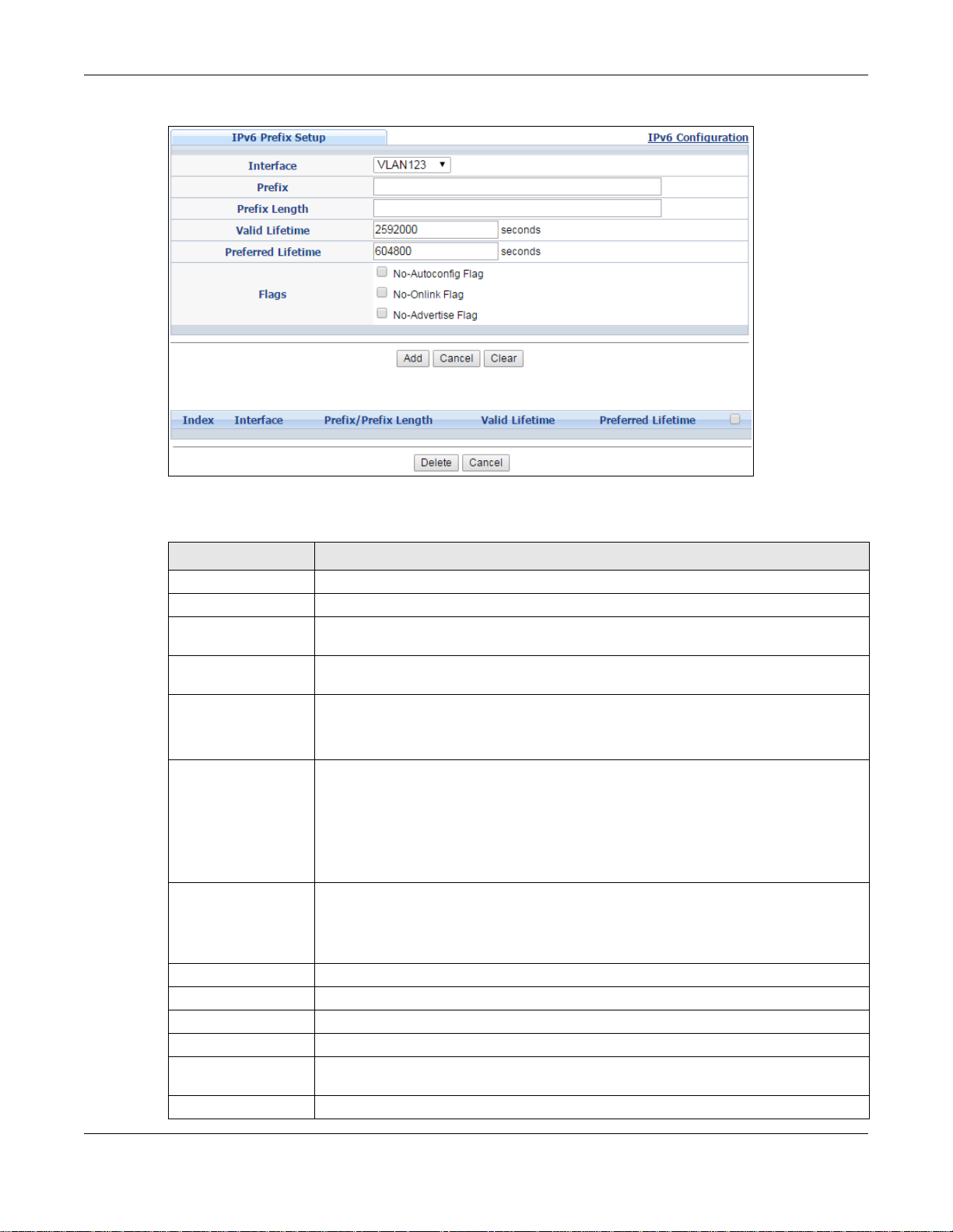
Chapter 8 Basic Setting
Figure 81 Basic Setting > IPv6 > IPv6 Configuration > IPv6 Prefix Setup
The following table describes the labels in this screen.
Table 33 Basic Setting > IPv6 > IPv6 Conf iguration > IPv6 Prefix Setup
LABEL DESCRIPTION
Interface Select the IPv6 interface you want to configure.
Prefix Set the IPv6 prefix that the Switch includes in router advertisements for this interface.
Prefix Length Set the prefix length that the Switch includes in router advertisements for this
interface.
Valid Lifetime Specify how long (from 0 to 4294967295 seconds) the prefix is valid for on-link
determination.
Preferred Lifetime Specify how long (from 0 to 4294967295 seconds) that addre sses gener ate d fr om the
Flags Select No-Autoconfig Flag to not allow IPv6 hosts to use this prefix for stateless
Add Click this to create a new entry or to update an existing one.
Cancel Click Cancel to begin configuring this screen afresh.
Clear Click Clear to reset the fields to the factory defaults.
Index This is the interface index number. Click on an index number to change the settings.
Interface This is the name of the IPv6 interface you created.
Prefix/Prefix Length This field displays the IPv6 prefix and prefix length that the Switch includes in router
Valid Lifetime This field displays the IPv6 prefix valid lifetime.
prefix via stateless address autoconfiguration remain preferred.
The preferred lifetime cannot exceed the valid lifetime.
address autoconfiguration.
Select No-Onlink Flag to not allow the specified prefix to be used for on-link
determination.
Select No-Advertise Flag to set the Switch to not include the specified IPv6 prefix,
prefix length in router advertisements for this interface.
This saves your changes to the Switch’s run-time memory. The Switch loses these
changes if it is turned off or loses power, so use the Save link on the top navigation
panel to save your changes to the nonvolatile memory when you are done configuring.
advertisements for this interface.
GS2210/XGS2210 Series User’s Guide
96
Page 97
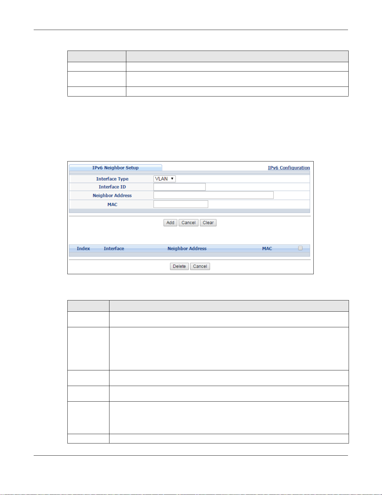
Table 33 Basic Setting > IPv6 > IPv6 Configuration > IPv6 Prefix Setup (continued)
LABEL DESCRIPTION
Preferred Lifetime This field displays the preferred lifetime of an IPv6 address generated from the prefix.
Delete Check the entry(ies) that you want to remove in the Delete column and then click
Delete to remove the selected entry(ies) from the summary table.
Cancel Click Cancel to clear the Delete check boxes.
8.10.10 IPv6 Neighbor Setup
Use this screen to create a static IPv6 neighbor entry in the Switch’s IPv6 neighbor table to store
the neighbor information permanently. Click the link next to IPv6 Neighbor Setup in the IPv6
Configuration screen to display the screen as shown next.
Figure 82 Basic Setting > IPv6 > IPv6 Configuration > IPv6 Neighbor Setup
Chapter 8 Basic Setting
The following table describes the labels in this screen.
Table 34 Basic Setting > IPv6 > IPv6 Conf iguration > IPv6 Neighbor Setup
LABEL DESCRIPTION
Interface Type Select the type of IPv6 interface for which you want to configure. The Switch supports the
Interface ID Specify a unique identification number (from 1 to 4094) for the interface.
Neighbor
Address
MAC Specify the MAC address of the neighboring device which can be reached through the
Add Click this to create a new entry or to update an existing one.
Cancel Click Cancel to begin configuring this screen afresh .
VLAN interface type for IPv6 at the time of writing.
A static IPv6 neighbor entry displays in the Management > Neighbor Table screen only
when the interface ID is also created in the Basic Setup > Interface Setup screen.
To have IPv6 function properly, you should configure a static VLAN with the same ID number
in the Advanced Application > VLAN screens.
Specify the IPv6 address of the neighboring device which can be reached through the
interface.
interface.
This saves your changes to the S witc h’s run-time memory. The Switch loses these changes if
it is turned off or loses power, so use the Save link on the top navigation panel to save your
changes to the nonvolatile memory when you are done configuring.
GS2210/XGS2210 Series User’s Guide
97
Page 98
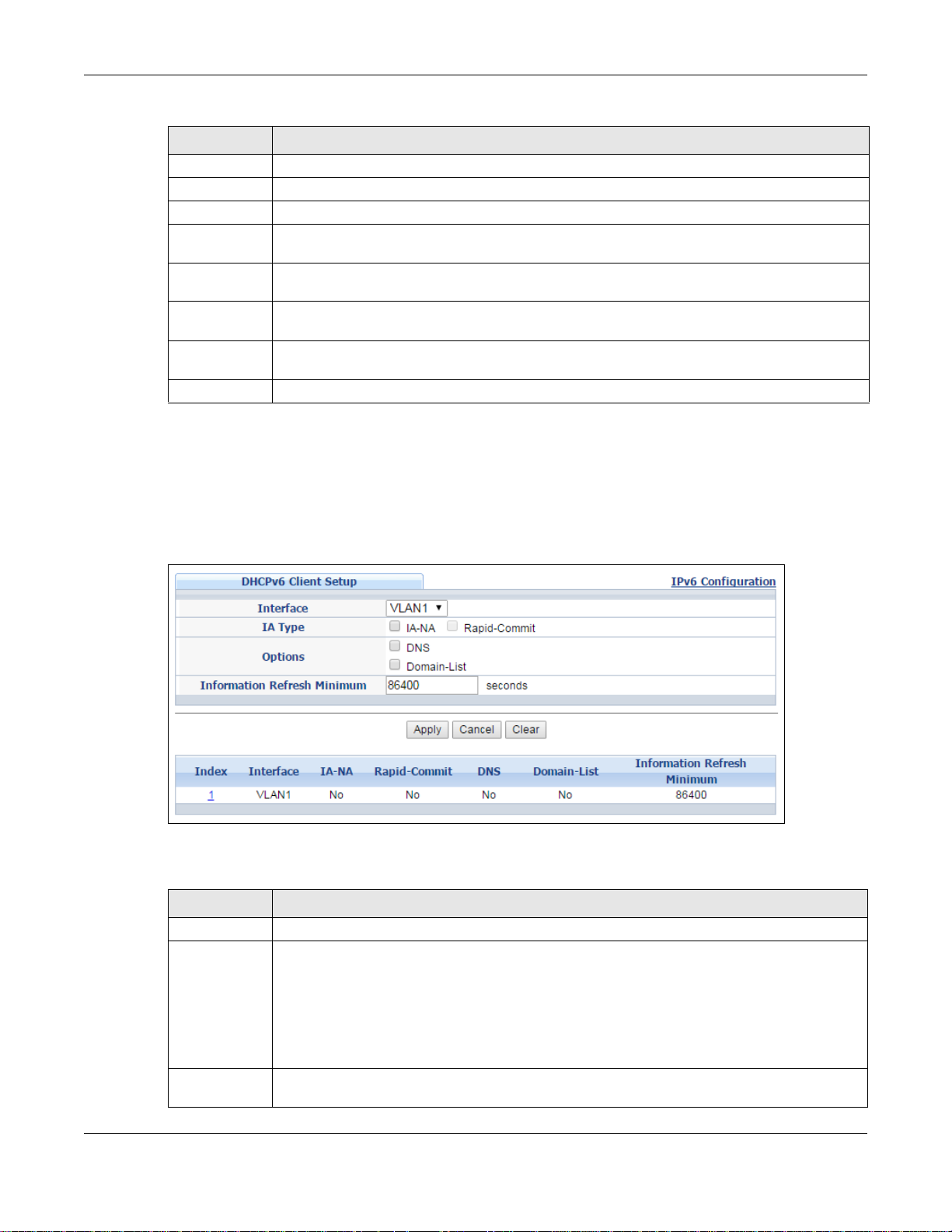
Table 34 Basic Setting > IPv6 > IPv6 Configuration > IPv6 Neighbor Setup (continued)
LABEL DESCRIPTION
Clear Click Clear to reset the fields to the factory defaults.
Index This is the interface index number. Click on an index number to change the settings.
Interface This is the name of the IPv6 interface you created.
Neighbor
Address
MAC This field displays the MAC address of the neighboring device which can be reached through
Delete Check the entry(ies) that you want to remove and then click Delete to remove the selected
Cancel Click Cancel to clear the check boxes.
This field displays the IPv6 address of the neighboring device which can be reached through
the interface
the interface.
Select an entry’s check box to select a specific entry. Otherwise, select the check box in the
table heading row to select all entries.
entry(ies) from the summary table.
8.10.11 DHCPv6 Client Setup
Use this screen to configure the Switch’s DHCP settings when it is acting as a DHCPv6 client. Click
the link next to DHCPv6 Client Setup in the IPv6 Configuration screen to display the screen as
shown next.
Chapter 8 Basic Setting
Figure 83 Basic Setting > IPv6 > IPv6 Configuration > DHCPv6 Client Setup
The following table describes the labels in this screen.
Table 35 Basic Setting > IPv6 > IPv6 Co nfiguration > DHCPv6 Client Setu p
LABEL DESCRIPTION
Interface Select the IPv6 interface you want to configure.
IA Type Select IA-NA to set the Switch to get a non-temporary IP address from the DHCPv6 server
Options Select DNS to ha ve the Switch obtai n DNS server IPv6 addresses and/or select Domain-List
for this interface.
Optionally, you can also select Rapid-Commit to have the Switch send its DHCPv6 Solicit
message with a Rapid Commit option to obtain information from the DHCPv6 server by a
rapid two-message exchange. The S witc h di scards any R eply messages that do not include a
Rapid Commit option. The DHCPv6 server should also support the Rapid Commit option to
have it work well.
to have the Switch obtain a list of domain names from the DHCP server.
GS2210/XGS2210 Series User’s Guide
98
Page 99
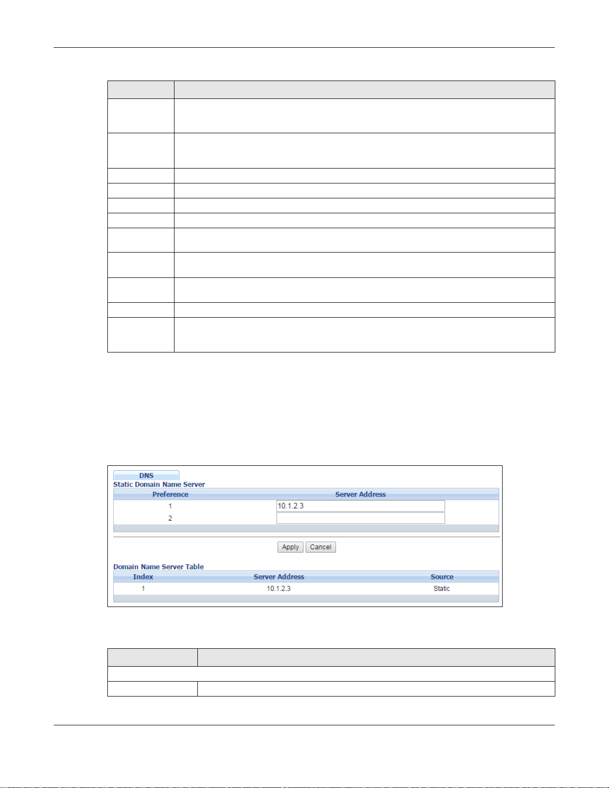
Chapter 8 Basic Setting
Table 35 Basic Setting > IPv6 > IPv6 Co nfiguration > DHCPv6 Client Setu p
LABEL DESCRIPTION
Information
Refresh
Minimum
Apply Click Apply to save your changes to t he Switch’s run-time memory. The Switch loses these
Cancel Click Cancel to begin configuring this screen afresh .
Clear Click Clear to reset the fields to the factory defaults.
Index This is the interface index number. Click on an index number to change the settings.
Interface This is the name of the IPv6 interface you created.
IA-NA This field displays whether the Switch obtains a non-temporary IP address from the DHCPv6
Rapid-Commit This field displays whether the Switch obtains information from the DHCPv6 server by a rapid
DNS This field displays whether the Switch obtains DNS server IPv6 addresses from the DHCPv6
Domain-List This field displays whether the Switch obtains a list of domain names from the DHCP server.
Information
Refresh
Minimum
Specify the time interval (from 600 to 4294967295 seconds) at which the Switch exchanges
other configuration information with a DHCPv6 server again.
changes if it is turned off or loses power , so use the Save link on the top navigation panel to
save your changes to the nonvolatile memory when you are done configuring.
server.
two-message exchange.
server.
This field displays the time interval (in seconds) at which the Switch exchanges other
configuration information with a DHCPv6 server again.
8.11 DNS
DNS (Domain Name System) is for mapping a domain name to its corresponding IP address and
vice versa. Use the DNS screen to configure and view the default DNS servers on the Switch.
Figure 84 Basic Setting > DNS
The following table describes the labels in this screen.
Table 36 Basic Setting > DNS
LABEL DESCRIPTION
Static Domain Name Server
Preference This is the priority of the DNS server address.
GS2210/XGS2210 Series User’s Guide
99
Page 100
Chapter 8 Basic Setting
Table 36 Basic Setting > DNS (continued)
LABEL DESCRIPTION
Server Address Enter a domain name server IPv6/IPv4 address in order to be able to use a domain
name instead of an IP address.
Apply Click Apply to save your changes to the Switch’s run-time memory. The Switch loses
these changes if it is turned off or loses power, so use the Save link on the top
navigation panel to save your changes to the nonvolatile memory when you are done
configuring.
Cancel Click Cancel to reset the fields to your previous configuration.
Domain Name Server Table
Index This field displays priority of the DNS server address.
Server Address This field displays the IP address of the DNS server.
Source This field displays whether the DNS server address is configured manually (Static) or
obtained automatically using DHCP/DHCPv6 (Dynamic).
GS2210/XGS2210 Series User’s Guide
100
 Loading...